Unication Co GSPAGER1 GS Digital Voice Pager User Manual
Unication Co Ltd GS Digital Voice Pager
UserManual.wiki
>
Unication Co
>
GSPAGER1 User Manual
User manual
Navigation menu
Upload a User Manual
Namespaces
Wiki Guide
HTML
PDF
Info
Views
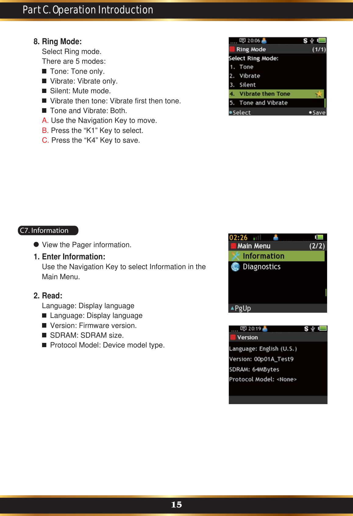
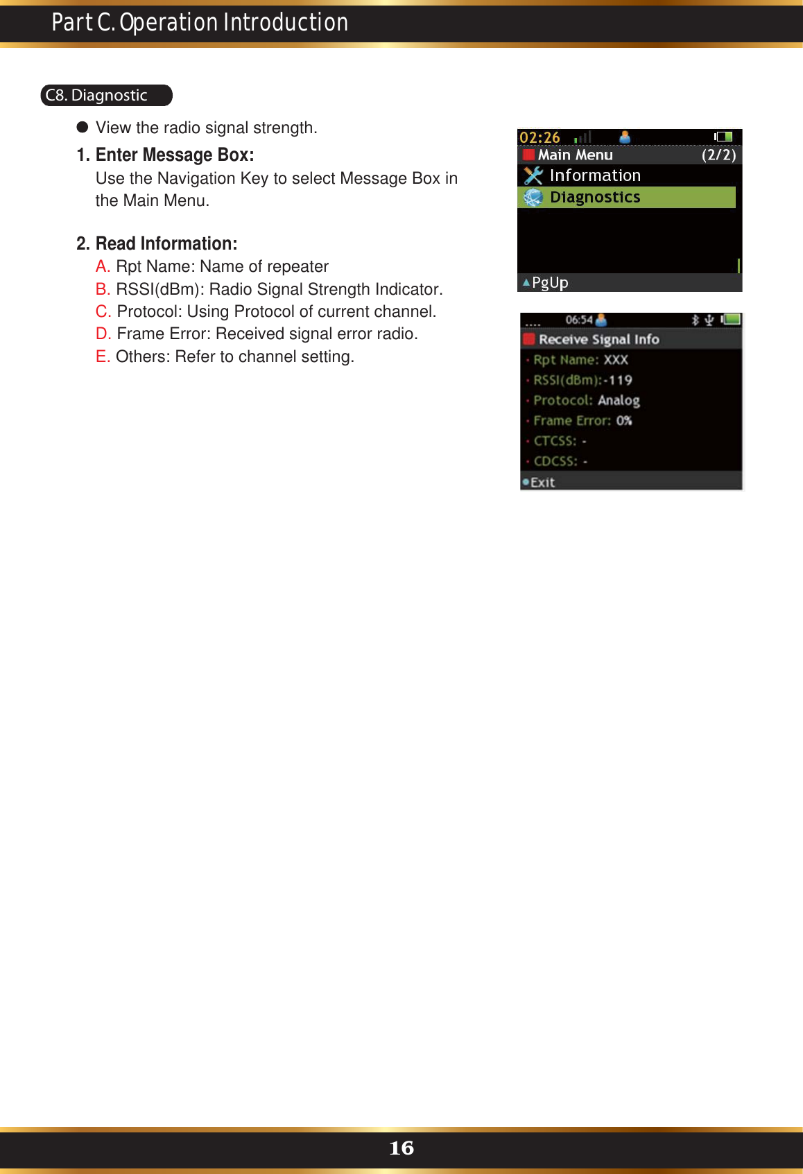
User Manual
Discussion / Help
Navigation