Unication Co GSPAGER1 GS Digital Voice Pager User Manual
Unication Co Ltd GS Digital Voice Pager
User manual
Any Time, Anywhere
Unication is committed to Provide You the Best Solution
,I\RXKDYHDQ\UHTXLUHPHQWVSOHDVHFDOORXUWROOIUHHQXPEHU
ZZZXQLFDWLRQFRP
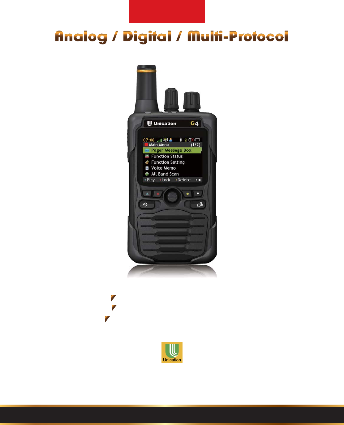
G
4
Voice Pager Supports
P25 Radio Systems Now!
Advanced Radio Performance
Mission Critical Applications
Optional GSM Features Available
Voice Pager Specially Designed for Public Safety
US-G4-FF-20150126-V1
d
vanced Radio Per
f
orman
ission Critical A
pp
licatio
n
i
o
n
a
l
G
S
M
F
e
a
t
u
r
e
s
A
v
a
i
l
a
e
ciall
y
Designed
f
or

4
4
5
5
6
7
7
8
9
11
12
13
15
16
17
1
B1 Pager Appearance
B2 LCD Display
B3 LED Introduction
B4 Icon Introduction
C1 Initial Use
C2 Pager Message Box
C3 Function status
C4 Voice Memo Box
C5 All Band Scan
C6 Function Setting
C7 Information
C8 Diagnostic
Part A: G4 Specifications and Features
Part D: Warning and Important Notes
Part B: Pager Overview
Part C: Operation Introduction
I N D E X
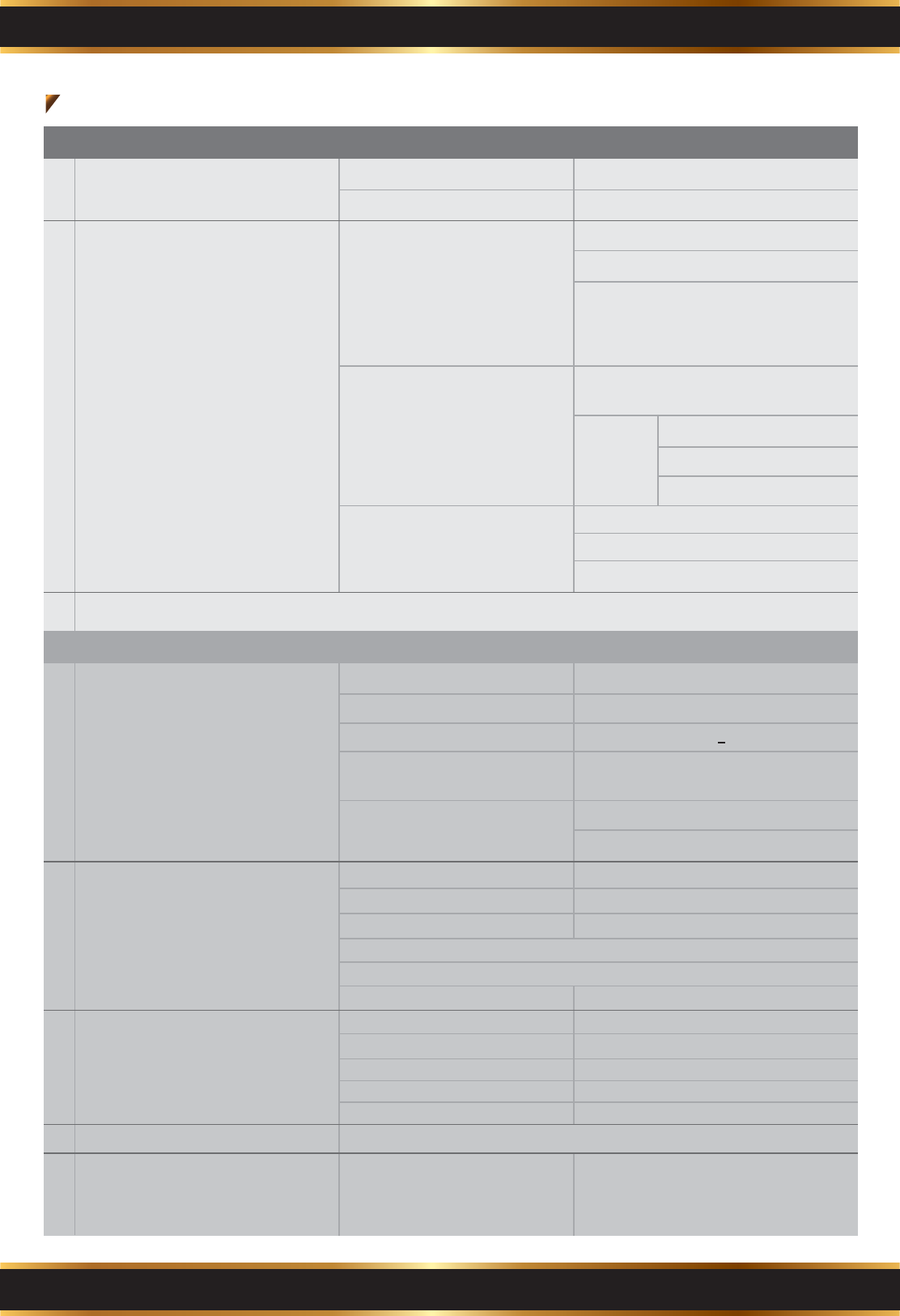
Part A. G4 Specifications and Features
a Physical Operating Environment
a Mechanical
bSystem Operating Environment
cApply to (Group)
Operating Temperature Range -30 to + 60°C
ESD (Electrostatic Discharge)
Available Modulation Type
contact ± 8KV Air ± 15KV
Available Support Protocol
Available Support Frequency
Range
Analog (AM / FM)
Analog : 2-Tone / 5-Tone / MDC 1200 /
CTCSS / CDCSS
Digital
VHF Band : 136MHz~174MHz
UHF Band : 406MHz~512MHz
700 / 800 MHz Band : 764MHz~870MHz
DMR Conventional
Digital (TDMA / FDMA)
Digital and Analog identify modulation
type and decode protocol automatically
at the same time. (on same channels and
same frequencies)
P25 Conventional
DMR Trunking
G4 Digital Trunking and Analog Voice Pager Specification & Feature
b
c
Operation Buttons
Display
d Backlights
Fixed and Carry Style Belt Clip
Drop Protection Pad
Display UV Protection
Size 102 x 61 x 31.5 (L*W*H /mm)
Power LED:
No Brightness – Power off / Power on
completed
9 lines x 22 characters
full color
13
4
8
1
<220 ( g )
Weight (g)
Dust / Waterproof
Special Requirement
Fixed Function Key
Soft Key
According to specification of MIL-810 &
Ingress Protection Rating is IP 67
Without Battery(g) :
Navigation Key
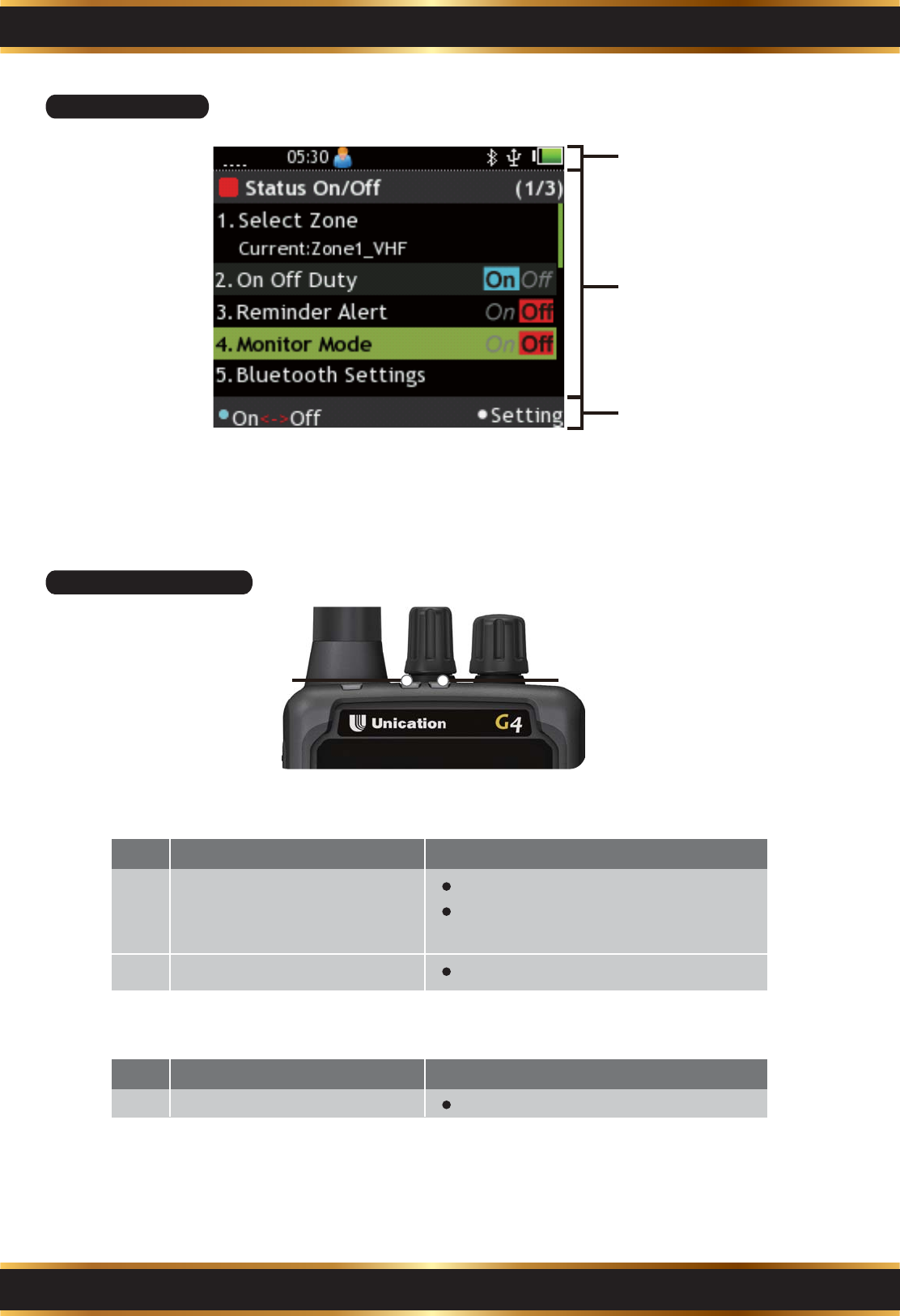
Power
Volume Control
Channel Switch
Saturation (grayscale / full color)
Characters & Length
Display Type
Size (length x wide)
Number of Dots 220 x 176
2.0 inches (30.6x40.8/mm)
LCD
Type (LED / EL ...) : LED
eLED LED Type (monochrome /
multicolor) : red / green / blue /
orange
A1 Operating Environment
A2 Hardware Specification
1

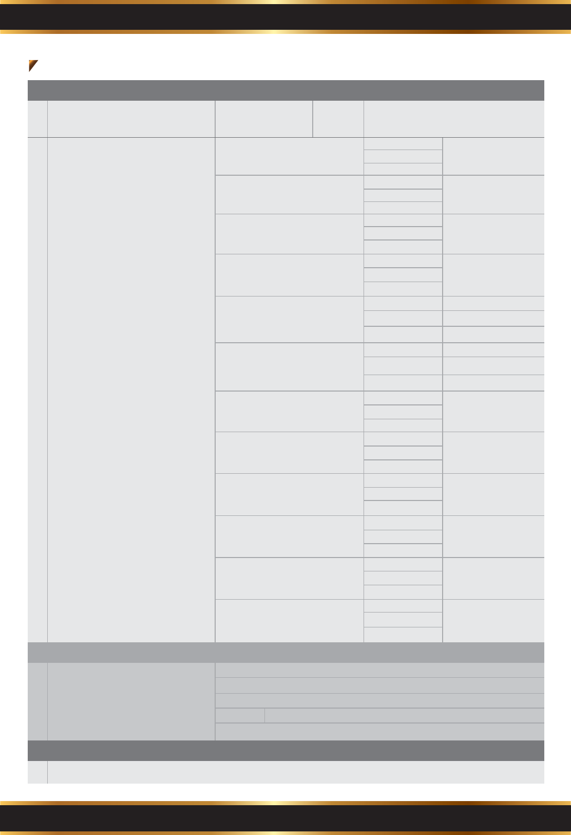
Part A. G4 Specifications and Features
eLED
fFrequency / Channel Specification
G4 Digital Trunking and Analog Voice Pager Specification & Feature
Blue - Power on / Connected with USB
cable / Charging completed
Flash Blue - Charging
Message LED: No Brightness – No signal
Red - Receiving voice call or data call
LED Type (monochrome /
multicolor) : red / green / blue /
orange
A2 Hardware Specification
A3 Electrical Characteristics
Number of Channels
Hardware : 8 (do not need to switch via
software)
Software : 64 (8 Ch / 8 Zone) (switch via
software)
Total : 64
Channel Spacing
Wied Band : 20/25k
Narrow Band :10/12.5k
Scan : 2.5k
Frequency Setting
Tone : Buzzer and speaker are the main device to be used as message alert
and reminder
Vibration : Motor and vibration speaker device are useful in meeting
Tone and Vibration : Alert tone and vibration remind users as the same time
Vibration then Tone : Vibrate first, then alert after few seconds
Blacklight : Coloured backlights indicate users to identify the important level
of each message, such as different colors, flashing backlights, different
brightness
LED : Different LED colors, flashing LED, different indicators
g Type of Alert
Power Interface : 5V/1.5A DC Internal Power Supply / Battery input interface
Data recording streaming
interface (PPS)
Wireless data streaming interface: (Bluetooth, WiFi…)
h External Port
Capcodes (Addresses)
Frequency / Channel
Specification of each channel
Analog
Digital
Mini USB
Battery type : (Alkaline battery,
Lithium Ion battery)
> 24 hrs
2-Tone protocol continuous
using 24 hrs per day
Receiving 5 mins of 2-Tone voice
message per hour
iPower Supply
Built-in Storage Memory:
(including voice, text & saving
time of data)
Battery Life : (Average bettery life
at 5/5/90 duty cycle, 3 paging per
day)
Voice
Text
Others (Photos / Profiles…)
j Storage Memory
1. Lithium Ion Rechargeable Battery
:3.7V / 2450mA
2. LiIon Rechargeable Battery:3.7V
/ 2450mA
Hum & Noise Ratio
< -57 dBw
> 34 dB
Squelch Level
Audio Distortion
Audio Distortion
Audio quality : Audio
input in 1KHz, then
modulated
by
system
a Audio Performance
< 2 % (Electrical)
< 3 % (Acoustic)
Play Back
SPL (12") : Alert
tone loudness at
12 inches
Alert
Output 96 +/- 2 dB SPL
Receive
< 3 % (Electrical)
< 4 % (Acoustic)
2
a Certification
FCC : Part 15 Subpart B / ICES-003
CE : EN55022 / EN55024 / EN61000-3-2 / EN61000-3-3
RoHS
UL Division 1, Class I, Group C, D, / Class II, Group E, F, G
MIL-STD
a Audio Amplification / Enhance receiving signal / LED Display / Relay / Remote control ( OTAC )
Part A. G4 Specifications and Features
G4 Digital Trunking and Analog Voice Pager Specification & Feature
A3 Electrical Characteristics
a Audio Performance SPL (12") : Alert
tone loudness at
12 inches
Speech
Output 94 +/- 2 dB SPL
b RF RX Performance
+/- 1 ppm
≦ 4.0 uv/m
≦ 2.5 uv/m
≦ 3.5 uv/m
≦-121dBm
Frequency Stability :
at the normal atmospheric
temperature (25°C)
Channel Spacing :
at (25 °C)
Alert Sensitivity 20 paging :
at (25 °C)
Message Sensitivity 20 paging :
(Voice Pager @ 12dB SINAD)
(Alpha Pager 3 Non-error) : at
(25 °C)
Low band
VHF
UHF
UHF
Low band
VHF
UHF
Low band
VHF
100% @ Paging
Sensitivity + 3 dB
Alert Probability VS RF Level:
at (25 °C) UHF
Low band
VHF
UHF
Low band
VHF
10/12.5/20/25 kHz
Low band
Low band
VHF
UHF
Intermodulation Rejection :
at (25 °C)
Co - Channal Rejection :
at (25 °C)
Low band
Low band
Spurious & Image Rejection :
at (25 °C)
Blocking Rejection :
at (25 °C)
Intermodulation High Level Third
Order Rejection : at (25 °C)
Low band
Low band
Message Probability VS RF
Level : (Voice Pager @ 12dB
SINAD) (Alpha Pager 3
Non-error) : at (25 °C)
Adjacent Channel Selectivity :
at (25 °C)
≦ 4.0 uv/m
≦ 2.5 uv/m
≦ 3.5 uv/m
VHF
VHF
> -8 dB
UHF
UHF
VHF ≧65 dB @ ±25 KHz
UHF
≧ 70dB @ Alert
≧ 70dB @12dB
SINAD
VHF ≧ 35 dB @PS.+60dB
UHF
VHF ≧ 70 dB
UHF
Low band
VHF ≧ 90 dB
UHF
A4 CERTIFICATION
B. Additional Function with unique accessaries
3
Part B. Pager Overview
4
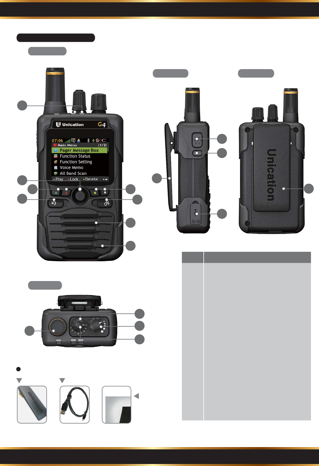
Belt Clip USB Cable
Lithium Ion
Battery Pack
Accessories
Description NO.
LED Indicator
Navigation Key
Soft Key (K1~K4)
Back Key (F2)
Home Key (F1)
Speaker
Microphone
Receive Antenna
Channel Knob
Play Key
Power on/off & Volume Knob
Reset Key
Function Status on/off Key (S1)
Mini USB Port
Belt Clip
Battery Cover
1
2
3
4
5
6
7
8
9
10
11
12
13
14
15
16
9
11
10
8
16
12
13
14
15
2
4
3 3
5
6
7
1
B1. Pager Appearance
Front View
Side View
Top View
Rear View
Part B. Pager Overview
5
B2. LCD Display
B3. LCD Introduction
Status Bar
Text Area
Tool Bar
Message LEDPower LED
Entity KeyNO. Description
Blue
Power on process
USB cable is connected to G4 and
charging is completed.
1
Flash Blue Charging2
Power LED:
Entity KeyNO. Description
Red Receiving voice call or data call1
Message LED:
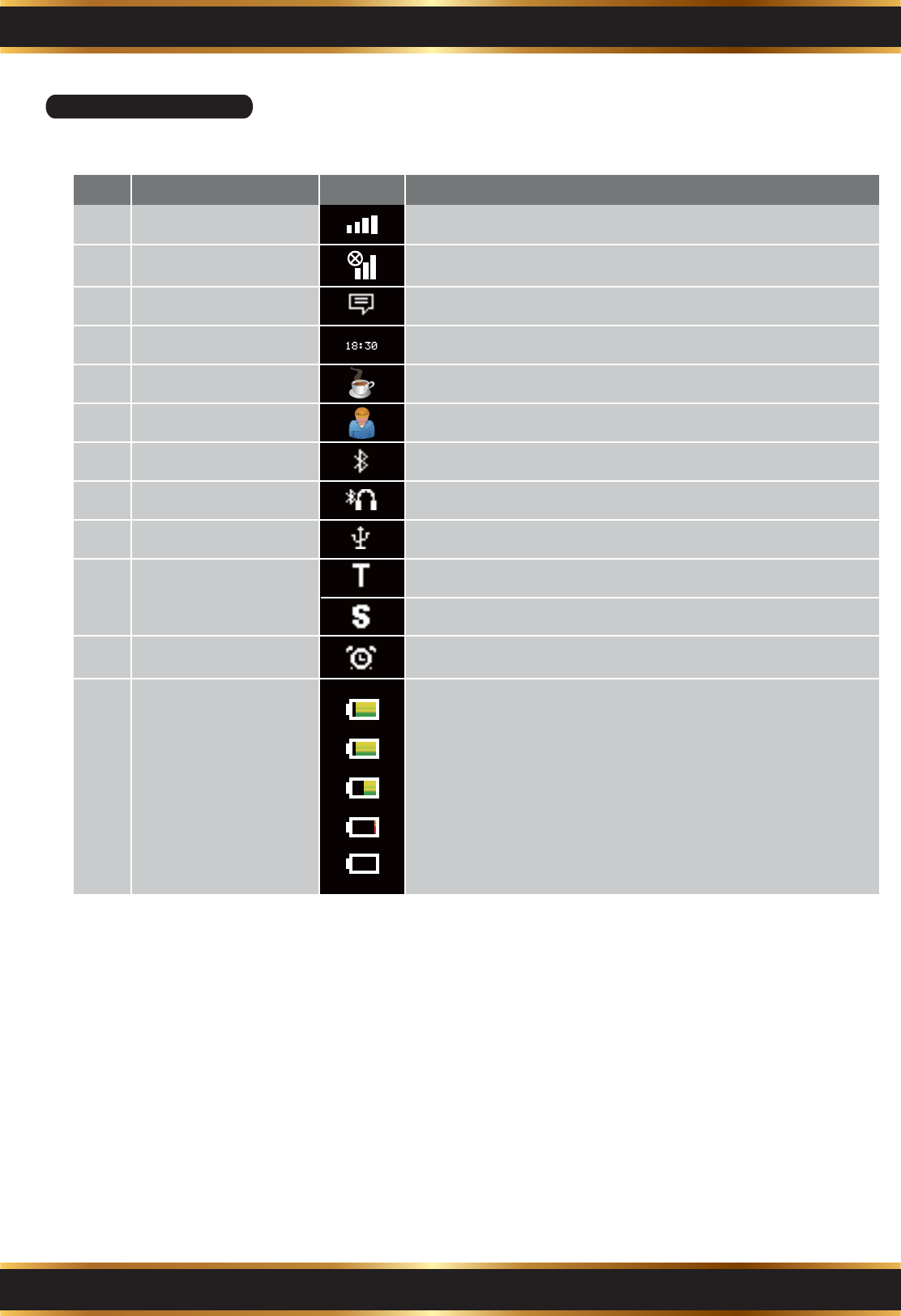
B4. Icon Introduction
Status Bar Icon
Part B. Pager Overview
6
Item IconNO.
RF Strength
Out of Range
Description
RF signal strength.
Signal is out of range.
1
2
Message Hint Unread message icon indication. 3
Time Display Time display (24 hour clock). 4
Off Duty Status Off duty status. 5
On Duty Status On duty status.6
Bluetooth Bluetooth is activated.7
Bluetooth Headset Bluetooth earphone is connected. 8
USB cable USB cable is connected.9
Trunking Status Trunking registered.
10
Trunking scanning.
Clock Alarm Clock alarm is activated.11
The battery gauge indicator is located on the status
bar and keeps you informed of the batery energy level.
The five indicators are:100%, 75%, 50%, less
0% (flashing battery icon).
Battery Status 12
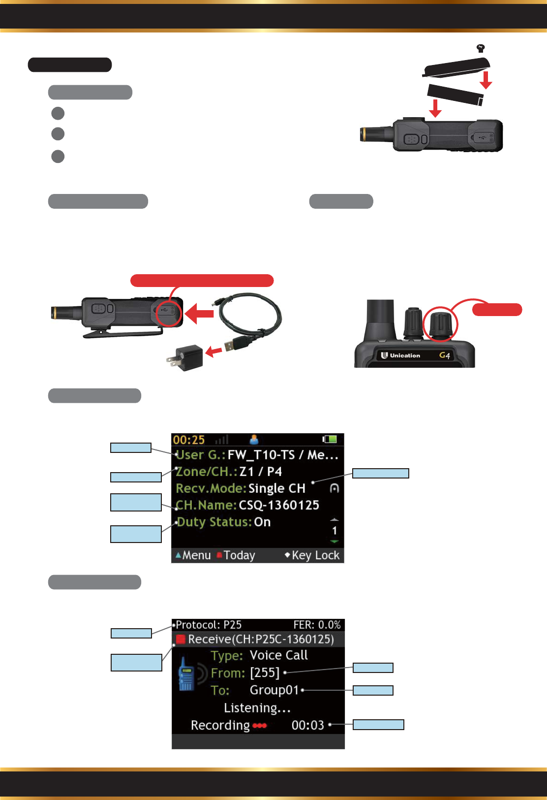
C1. Initial Use
On the standby screen, G4 displays information on the current receiving mode.
G4 displays the information of the incoming call when receives a message.
Part C. Operation Introduction
7
Battery Charging
Install Battery
Standby Screen
Receive Message
USB power specification: 5V/1A
G4 has its own customized lithium
Ion battery, it can be charged by mini
USB cable.
Power on
Power On
After the battery installed , turn the
volume knob clockwise to turn on G4.
You will hear “click” sound and see the
word of “Loading” on the display.
Turn the screws and remove the battery cover.
Insert the battery pack into G4.
Replace the battery cover and and tighten the
screws.
2
3
1
Band
Receiving Mode
User Group
Zone/Channel
Main Channel
Name
Duty Status
(With Alarm)
Caller ID
Caller ID
Call Duration
Band
Protocol
Receiving
Channel
Insert the battery so that the connector pins align
with battery contacts of the G4.
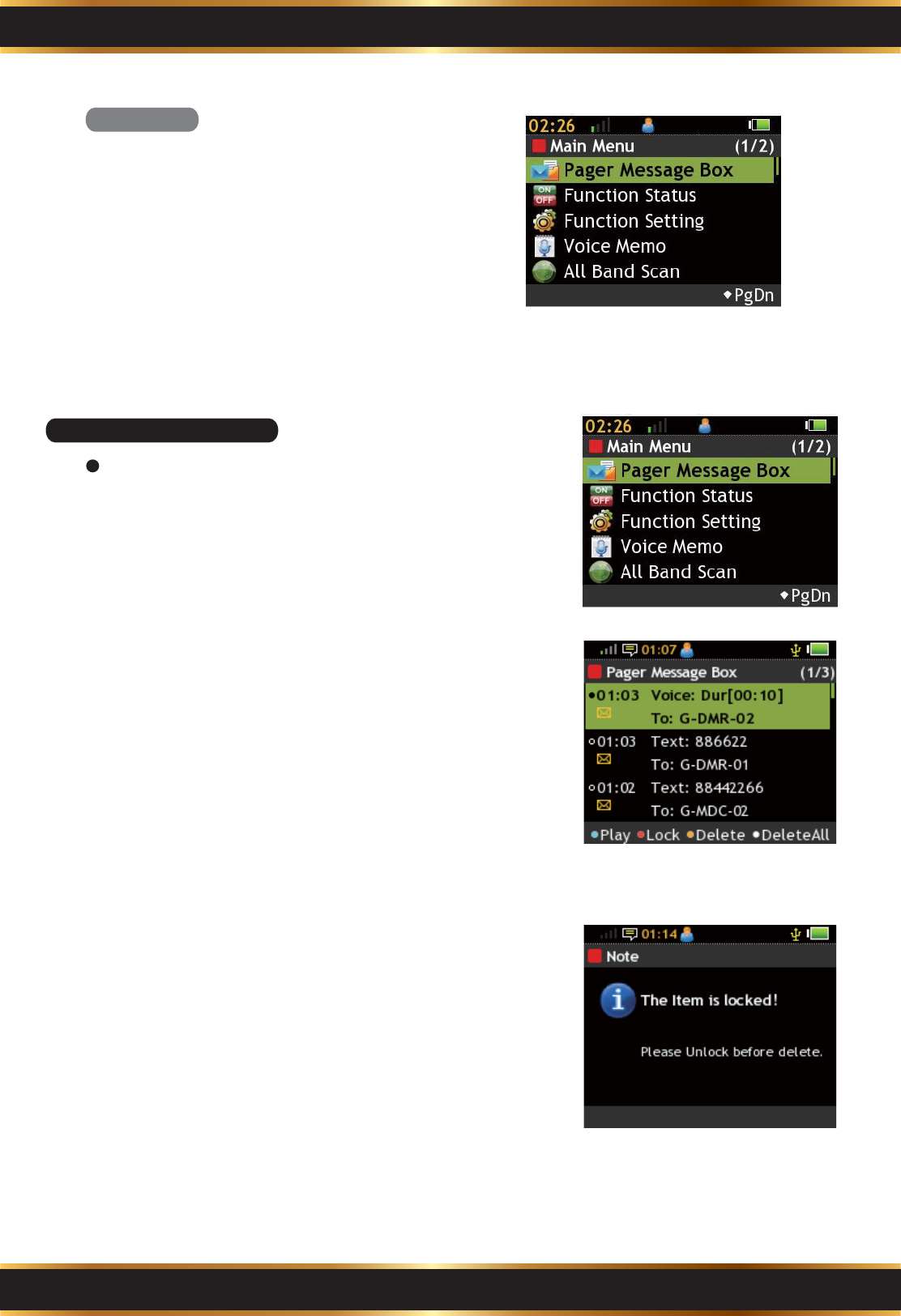
In Standby Mode, press the “K1” soft key to
enter the Main Menu.
1.
Press the “Home” key to go back to Standby
Mode.
2.
Main Menu
Part C. Operation Introduction
8
C2. Pager Message Box
View and Manage Text Message Records in
Message Box.
Enter Message Box:
Use the Navigation Key to select Message Box in
the Main Menu.
Operation:
A. Use the Navigation Key to select Message.
B. Press the "K1" Key to read highlighted message.
C. Press the “K2” Key to lock/unlock highlighted
message. A lock icon shows on a locked
message.
D. Press the “K3” Key to delete highlighted message.
E. Press the “K4” to delete all messages.
1.
2.
Read Message:
A. Use the Navigation Key to scroll the message.
B. Press the “K1” Key to lock/unlock the message.
Note: A locked item cannot be deleted.
3.
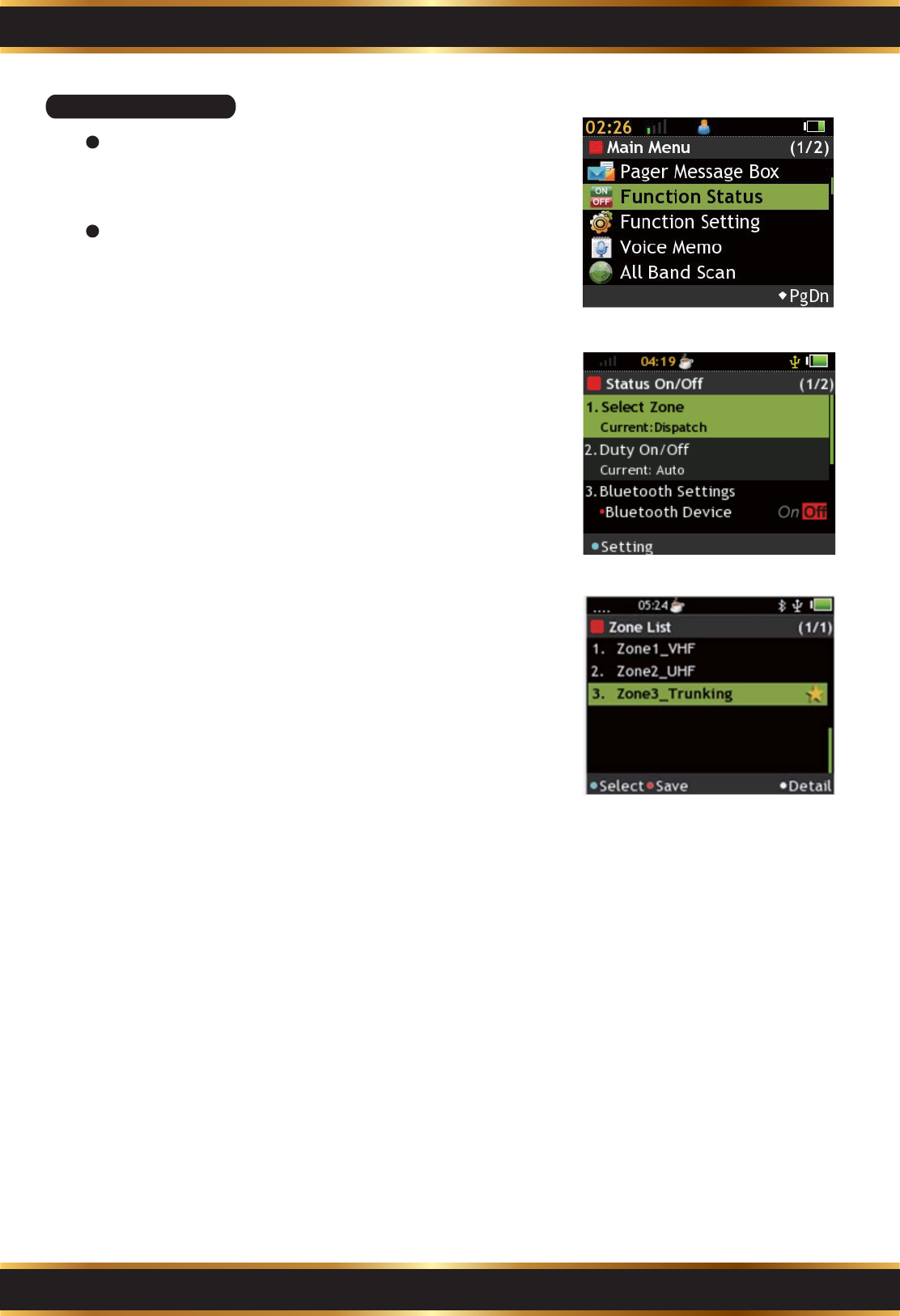
C3. Function status
Enter Function Status:
Use
the
Navigation key to select Function Status in
the
Main Menu.
Select Zone:
Press the "K1" Key to enter setting screen. Use
the Navigation Key to select Zone and then press
the “K1” Key to confirm. Press the “K2” Key to save.
You can press the “K4” Key to check detailed
information of highlighted Zone.
On Off Duty:
Press the “K1” Key to enable or disable the feature.
If On Off Duty is disabled, the speaker is muted
when receiving messages.
Basic Operation:
Use the Navigation Key to select features to set.
1.
2.
Part C. Operation Introduction
9
Part C. Operation Introduction
10
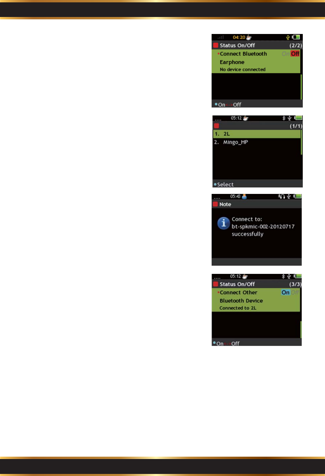
Bluetooth:
Bluetooth Device: Press the "K1" Key to enable or
disable the feature.
Connect Bluetooth Earphone: Press the "K1" Key
to start searching for the Bluetooth Earphone
devices.
Connect another Bluetooth Device: Press the “K1”
to start searching for Bluetooth devices other than
earphone.
If only a Bluetooth device is found, the G4 starts
pairing to the device. The G4 shows the pairing
status on the screen.
If there are 2 or more devices, use the Navigation
Key to select device and press the “K1” Key to start
pairing.
Press the “K1” Key to stop Bluetooth pairing.
3.
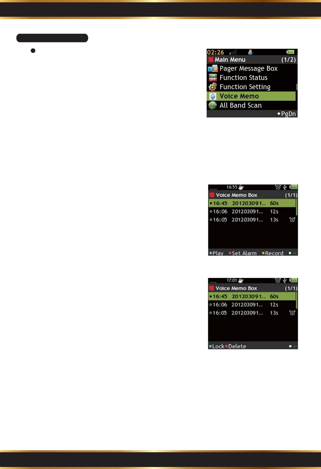
C4. Voice Memo Box
Part C. Operation Introduction
11
View and Manage Voice Memo in Voice Memo
Box.
Enter Voice Record Box:
Use the Navigation Key to select the Voice Memo
Box in the Main Menu.
Record a New Voice Memo:
If there is no voice memo, press the “K1” Key to
start recording.
A. Press the “K1” Key to pause.
B. Press the “K4” Key to save the voice memo.
C. Press the “K1” Key to set the voice memo as
Alarm.
D. Press the “F2” Key to back to Voice Memo box.
1.
2.
Set Alarm:
A. Use the Navigation Key to move.
B. Press the “K1” Key to make highlighted value +5.
C. Press the “K2” Key to make highlighted value +1.
D. Press the “K3” Key to make highlighted value -1.
E. Press the “K4” Key to save.
4.
Voice Memo:
View and manage the voice memos.
Features page 1:
A. Press the “K1” Key to play highlighted voice memo.
B. Press the “K2” Key to set highlighted voice memo
as Alarm.
C. Press the “K3” Key to record a new voice memo.
D. Press the “K4” Key to switch to features page 2.
Features page 2:
E. Press the “K1” Key to lock/unlock the highlighted
item.
F. Press the “K2” Key to delete the highlighted item.
G. Press the “K4” Key to switch to features page 1.
3.
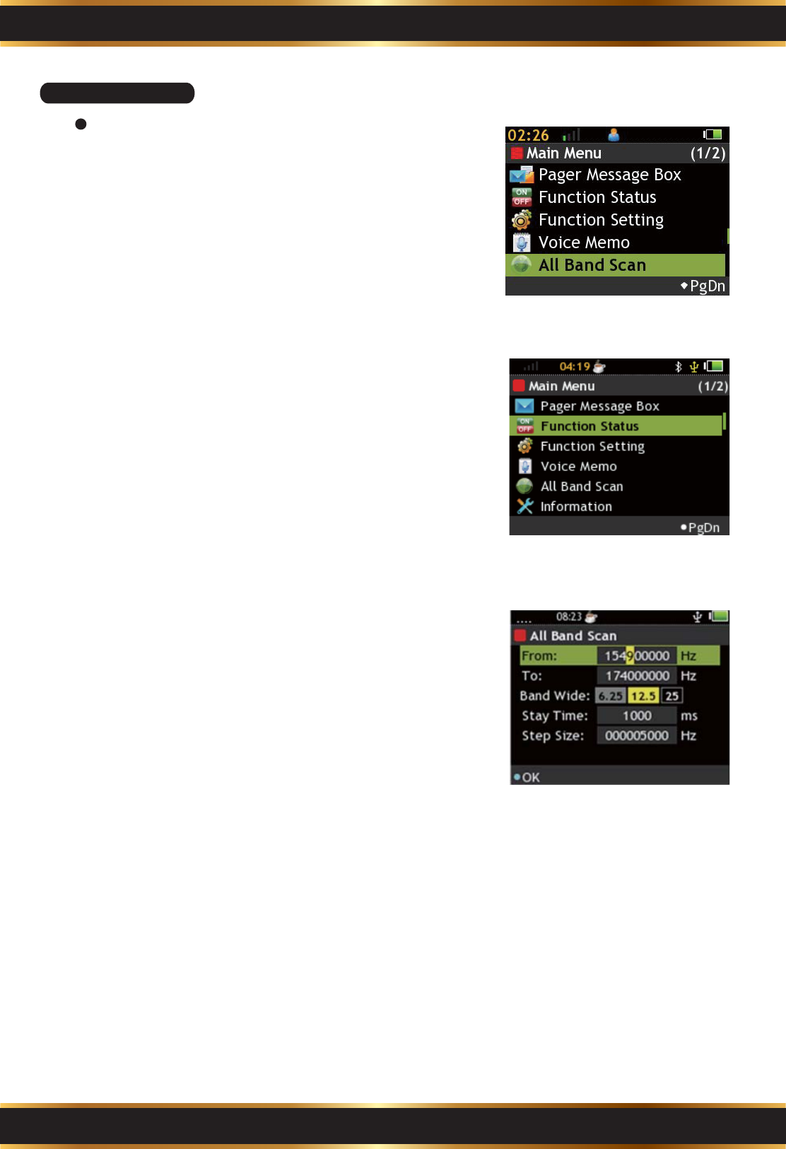
C5. All Band Scan
Part C. Operation Introduction
12
Set a range to scan, or view the scanned channel
list.
Enter Voice Record Box:
A. Use the Navigation Key to select All Band Scan in
the Main Menu.
B. Use the Navigation Key to select a feature, and
press the “K1” key to enter.
C. Press the “K1” Key to set the voice memo as Alarm.
D. Press the “F2” Key to back to Voice Memo box.
1.
Start a New Scan:
Set scan range, band and frequency step.
A. Use the Navigation Key to move.
B. Press the “K1” Key to set the highlighted item.
Use the Navigation Key to adjust numeric value.
C. Press the “K4” Key to start scanning.
D. Press the “K1” Key to stop scanning.
2.
Active Frequency List:
View and manage scanned channel list.
A. Use the Navigation Key to move.
B. Press the “K1” Key to monitor the highlighted
channel.
C. Press the “K2” Key to lock the highlighted channel.
D. Press the “K3” Key to delete the highlighted channel.
E. Press the “K4” to delete all scanned channels.
3.
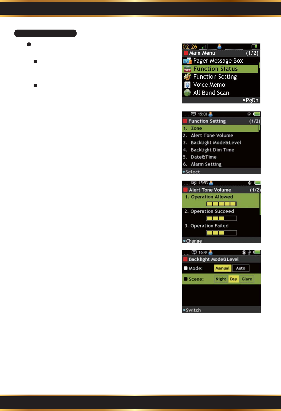
C6. Function Setting
Part C. Operation Introduction
13
View and manage pager basic function.
Enter Function Status:
Use the Navigation Key to select Function
Setting in the Main Menu.
Basic Operation:
Use the Navigation Key to select function.
Press “K1” Key to start setting.
Zone:
Please refer C2-1 to get detailed information.
1.
Alert Tone Volume:
Use the “K1” Key to adjust the pager tone volume.
A. Operation Allowed: Operation successed.
B. Operation Succeed: Message received.
C. Operation Failed: Message receiving failed.
D. Message Arrived: Text message received.
E. Alarm: Alarm volume
2.
Backlight Mode&Level:
Use the “K1” Key to adjust backlight mode.
A. Mode: Select the backlight mode. There are 2
modes: “Manual” or “Auto”.
B. Manual: Night is low level, Day is medium and
Glare is high level of backlight.
3.
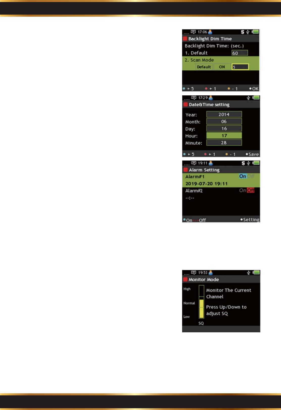
Part C. Operation Introduction
14
Backlight Dim Time:
Adjust screen backlight dim time.
A. Use the Navigation Key to move.
B. Press the “K1” Key to make highlighted value +5.
C. Press the “K2” Key to make highlighted value +1.
D. Press the “K3” Key to make highlighted value -1.
E. Press the “K4” Key to save.
4.
Date & Time:
Adjust Time of pager.
A. Use the Navigation Key to move.
B. Press the “K1” Key to make highlighted value +5.
C. Press the “K2” Key to make highlighted value +1.
D. Press the “K3” Key to make highlighted value -1.
E. Press the “K4” Key to save.
5.
Monitor Mode:
Please refer to C2-4 for more detailed
information.
7.
Alarm Setting:
Set up to 2 sets of Alarm.
A. Use the Navigation Key to move.
B. Press the “K1” Key to activate the Alarm.
C. Press the “K4” Key to set.
Alarm setting:
A. Use the Navigation Key to move.
B. Press the “K1” Key to make highlighted value +5.
C. Press the “K2” Key to make highlighted value +1.
D. Press the “K3” Key to make highlighted value -1.
E. Press the “K4” Key to save.
6.
Part C. Operation Introduction
15
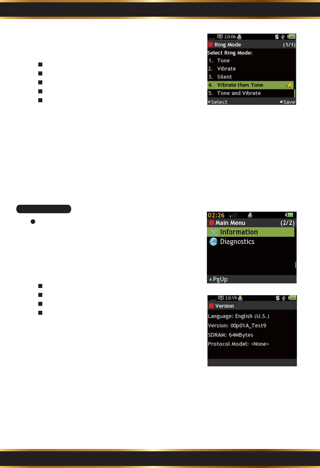
Ring Mode:
Select Ring mode.
There are 5 modes:
Tone: Tone only.
Vibrate: Vibrate only.
Silent: Mute mode.
Vibrate then tone: Vibrate first then tone.
Tone and Vibrate: Both.
A. Use the Navigation Key to move.
B. Press the “K1” Key to select.
C. Press the “K4” Key to save.
8.
C7. Information
View the Pager information.
Enter Information:
Use the Navigation Key to select Information in the
Main Menu.
1.
Read:
Language: Display language
Language: Display language
Version: Firmware version.
SDRAM: SDRAM size.
Protocol Model: Device model type.
2.
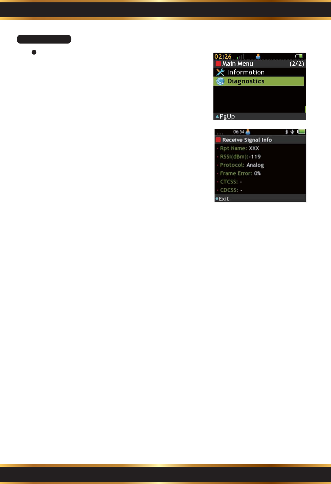
C8. Diagnostic
View the radio signal strength.
Enter Message Box:
Use the Navigation Key to select Message Box in
the Main Menu.
1.
Read Information:
A. Rpt Name: Name of repeater
B. RSSI(dBm): Radio Signal Strength Indicator.
C. Protocol: Using Protocol of current channel.
D. Frame Error: Received signal error radio.
E. Others: Refer to channel setting.
2.
Part C. Operation Introduction
16
Notice :
The changes or modifications not expressly approved by the party responsible for compliance could void
the user’s authority to operate the equipment.
Antenna :
To reduce potential radio interference to other users, the antenna type and its gain should be so chosen
that the equivalent isotropically radiated power (EIRP) is not more than that required for successful
communication.
This device has been designed to operate with an antenna having a maximum gain of -2 dBi. Antenna
having a higher gain is strictly prohibited per regulations of Industry Canada. The required antenna
impedance is 50 ohms.
Important Note :
To comply with the FCC RF exposure compliance requirements, no change to the antenna or the device
is permitted. Any change to the antenna or the device could result in the device exceeding the RF
exposure requirements and void user’s authority to operate the device.
IC Note :
The term “IC:” before the radio certification number only signifies that Industry Canada Technical
specifications were met.
Operation is subject to the following two conditions: (1) this device may not cause interference, and
(2) this device must accept any interference, including interference that may cause undesired operation of
the device.
Le présent appareil est conforme aux CNR d'Industrie Canada applicables aux appareils radio exempts de
licence. L'exploitation est autorisée aux deux conditions suivantes : (1) l'appareil ne doit pas produire de
brouillage, et (2) l'utilisateur de l'appareil doit accepter tout brouillage radioélectrique subi, même si le
brouillage est susceptible d'en compromettre le fonctionnement.
Part D. Warning and Important Notes
17