Uniden America UB316 Trunk Tracking Digital Capable Scanner User Manual Draft Owners Manual
Uniden America Corporation Trunk Tracking Digital Capable Scanner Draft Owners Manual
Draft Owners Manual

Band Frequency Range Mode Step
No. (MHz) (kHz)
15 162.0000 - 173.9875 FM 12.5
16 174.0000 - 215.9500 WFM 50
17 216.0000 - 224.9950 FM 5
18 225.0000 - 399.9500 AM 50
19 400.0000 - 405.9875 NFM 12.5
20 406.0000 - 419.9875 NFM 12.5
21 420.0000 - 449.9875 NFM 12.5
22 450.0000 - 469.9875 NFM 12.5
23 470.0000 - 512.0000 NFM 12.5
24 806.0000 - 823.9875 NFM 12.5
25 849.0125 - 868.9875 NFM 12.5
26 894.0125 - 956.0000 NFM 12.5
27 1240.0000 - 1300.0000 NFM 12.5
Band Frequency Range Mode Step
No. (MHz) (kHz)
1 25.0000 - 26.9600 AM 5
2 26.9650 - 27.4050 AM 5
3 27.4100 - 27.9950 AM 5
4 28.0000 - 29.6900 FM 10
5 29.7000 - 49.9900 FM 10
6 50.0000 - 53.9900 FM 10
7 54.0000 - 71.9500 WFM 50
8 72.0000 - 75.9950 FM 5
9 76.0000 - 87.9500 WFM 50
10 88.0000 - 107.9000 WFM 100
11 108.0000 - 136.9750 AM 25
12 137.0000 - 143.9950 FM 5
13 144.0000 - 147.9950 FM 5
14 148.0000 - 161.9950 FM 5
Introduction
The BC780XLT is a state-of-the-art radio with TrunkTracking™ and automatic scanning
capabilities. It can store frequencies such as police, fire/emergency, marine, railroad, air,
amateur, and other communications into 10 banks of 50 channels each.
Use your new scanner to monitor:
• Police and Fire Departments (including rescue and paramedics)
• VHF High Band, UHF, 800/900 MHz Trunked Public Safety Systems
• Trunking for Motorola, EDACS and LTR Systems
• NOAA Weather Broadcasts
• Business/Industrial Radio
• Utilities
• Marine and Amateur (ham radio) Bands
• Air Band
• And much more...
The chart below identifies the scanner band numbers, the frequency range, the modulation
mode and the default step size settings.

1
Important Notice
•This scanning radio has been manufactured so that it will not tune radio frequencies
assigned by the FCC for cellular telephone usage. The Electronic Communications Privacy
Act of 1986, as amended, makes it a federal crime to intentionally intercept cellular or
cordless telephone transmissions or to market this radio when altered to receive them.
•The installation, possession, or use of this scanning radio in a motor vehicle may be
prohibited, regulated, or require a permit in certain states, cities, and/or local jurisdictions.
Your local law enforcement officials should be able to provide you with information
regarding the laws in your community.
•Changes or modifications to this product not expressly approved by Uniden, or operation
of this product in any way other than as detailed by this Operating Guide. These violations
could void your authority to operate this product.
•The screen displays used in this manual are representations of what might appear when
you use your scanner.

2
Terminology
What is Scanning?
Unlike standard AM or FM radio stations, most two-way communications do not transmit
continuously. The BC780XLT scans the channels you program until it finds an active
frequency.
Scanning stops on an active frequency and remains on that channel as long as the
transmission continues. When the transmission ends, the scanning cycle resumes until
another transmission is received.
What is Searching?
The BC780XLT can search each of its 27 bands to find active frequencies. This is different
from scanning because you are searching for frequencies that have not been programmed
into your scanner. The scanner automatically chooses between two speeds while searching.
Turbo Search, can search the VHF FM bands at up to 300 channels per second.
What is Trunk Tracking?
Conventional scanning is a simple concept. You enter a radio frequency in your scanner’s
memory which is used by someone you want to monitor. For example, the police in your
area may broadcast on 460.500 MHz, the fire department on 154.445 MHz, the highway
department on 37.900 MHz, etc. So when your scanner stops on a frequency, you usually
know who it is, and more importantly, you can stop on a channel and listen to an entire
conversation. This type of scanning is easy and fun.
As the demand for public communications has increased, many public radio users don't
have enough frequencies to meet their needs, and this has created a serious problem.
Trunking radio systems solve this problem.
In a trunked radio system, which contains up to 28 different frequencies, radio users are
divided into groups, often called talkgroups, and these talkgroups are assigned specific IDs.
When someone in a talkgroup uses their radio, a brief burst of data is broadcasted before
each transmission. The trunking system computer uses this data to temporarily assign each
radio in a talkgroup to an available frequency. If the group using a frequency stops
broadcasting or pauses between replies for a few seconds, they are removed from the
frequency so another talkgroup can use it.
Sharing of the available public service frequencies, or trunking, allows cities, counties, or
other agencies to accommodate hundreds of users with relatively few frequencies. Following
a conversation on a trunked system using a scanner is difficult, if not impossible. Because
when there's a short break during the conversation you're monitoring, it’s possible that the
talkgroup will be assigned to a completely different frequency in the trunked system. This
type of scanning is difficult and frustrating.
3
TrunkTrack™changes this! Not only does your new BC780XLT scan channels like a
conventional scanner, it actually follows the users of a trunked radio system. Once you know
a talkgroups ID, you won’t miss any of the action.
If you're a new scanner enthusiast, you may want to read the first part of this manual and
use your scanner in conventional mode before you begin trunk tracking. Understanding
scanning fundamentals and its terminology will make trunk tracking much easier. A glossary
of other commonly used terms is provided in the back. (Refer to the "Glossary of Terms"
section.) But if you're already an experienced scanner operator, you may want to skip to
Trunked System on page 36.

4
Feature Highlights
•Trunk Tracking – Follow UHF High Band UHF 800/900MHz trunked public safety and
public service systems just as if conventional two-way communications were used.
•Multi-Track – Track more than one trunking system at a time. Scan conventional and
trunked systems at the same time.
•500 Channels – Program one frequency into each channel. You must have at least one
channel programmed to use the Scan mode.
•27 Bands, 10 Banks – Includes 27 bands, with Aircraft and 800 MHz.10 banks with 50
channels each are useful for storing similar frequencies to maintain faster scanning cycles
or for storing all the frequencies of a trunked system.
•25 MHz-1300 MHz – Indicates the range of frequencies that can be searched within the
bands of your scanner.
Note: The frequency coverage is not continuous and excludes the cellular band,
512-806MHz.
•10 Priority Channels – You can assign one priority channel in each bank. Assigning a
priority channel allows you to keep track of activity on your most important channel(s)
while monitoring other channels for transmissions. You can also assign trunking priority
talkgroups.
•Preprogrammed Service (SVC) Search – Allows you to toggle through preprogrammed
public safety, news media, TV broadcast audio, Ham, CB, FRS, special low power,
railroad, aircraft, marine, and weather frequencies.
•Unique Data Skip – Allows your scanner to skip unwanted data transmissions and
reduces birdies.
•Memory Backup – If power is disconnected, the frequencies programmed in your scanner
are retained in memory.
•Manual Channel Access – Go directly to any channel.
•Attenuator – Reduces the signal strength on a per frequency basis.
•PC Programmable – Allows you to easily program all frequencies and Trunking Talk
Groups into your BC780XLT through third party software running on your PC.
•Turbo Search – Increases the search speed to 300 steps per second. This applies only to
transmission bands with 5 kHz steps.
•Text Tags – You can customize your scanner by storing text tags (up to 16 characters).
•Auto Store – The scanner automatically arranges a memory store for searched frequencies.
•CTCSS/DCS – The scanner can receive and search for subaudible tones.
•NWR-SAME Alert – The scanner is compatible with warning tone and message
transmissions.
•FIPS Code – Six digit FIPS Code (emergency and geographic area code) programmable.

5
Where to Obtain More Information
Before using your scanner, you must program frequencies into available channels. The Betty
Bearcat Frequency Guide lists typical frequencies used around the U.S.A. and Canada that
you may program into your new scanner.
To obtain another copy of the frequency guide, contact one of the following:
•Uniden Parts Department
(800) 554-3988 (Hours are from 7:00 a.m. to 5:00 p.m. Central Time
Monday through Friday.)
•Local Dealer
To obtain additional frequency information for your area, contact one of the following:
•Bearcat Frequency Hotline
(937) 299-0414 (Hours are from 9:00 a.m. to 5:00 p.m. Eastern Time
Monday through Friday.)
•Bearcat Radio Club
(800) 423-1331 (Hours are from 8:00 a.m. to 5:00 p.m. Eastern Time
Monday through Friday.)
•Scanner Master
(800) 722-6701 (Hours are from 10:00 a.m. to 5:00 p.m. Eastern Time
Monday through Friday.)
Information on the Internet
If you have access to the Internet, you may want to visit one of the following websites for
additional information:
scanner.uniden.com
www.bearcat1.com
www.uniden.com

7
Setup
Connecting an Antenna
You must install an antenna before you can operate the scanner. You have been provided a
standard telescopic antenna that works well with this scanner, but you may want to
purchases another type to increase the range. To connect the telescopic antenna, simply
connect it to the BNC type ANT. connector on the rear of the scanner. You can purchase a
variety of scanner antennas for both mobile and base station available at a local electronics
store. Choose the one that best meets your needs.
When deciding on a mobile or base station antenna and its location, consider these points.
•The antenna should be as high as possible on a vehicle or a house.
•The antenna and its cable should be as far as possible from sources of electrical noise
(ignition systems, gauges, and so on).
•The antenna should be vertical for the best performance.
Mounting an Antenna
Once you choose an antenna, follow the mounting instructions supplied with the antenna.
Then route the antenna cable to the scanner.
The antenna connector on your scanner makes it easy to use the scanner with a variety of
antennas, such as an external mobile antenna or an outdoor base station antenna.
Always use 50 ohm coaxial cable, such as RG-58 or RG-8, to connect an outdoor antenna.
For lengths over 50 feet, use RG-8 low-loss dielectric coaxial cable If your antenna’s cable
does not have a BNC connector, you will also need a BNC adapter (available at a local
electronics store).
Follow the Installation instructions supplied with the antenna, route the antenna cable to the
scanner, then connect it to the ANT. jack.
Warning: Use extreme caution when you install or remove an outdoor antenna. If the
antenna starts to fall, let it go! It could contact overhead power lines. If the
antenna touches a power line, contact with the antenna, mast, cable, or guy
wires can cause electrocution and death. Call the power company to remove
the antenna. DO NOT attempt to do it yourself.
Optional Antenna
If you have chosen an optional mobile antenna, connect the antenna plug into the ANT.
connector on the rear of the scanner. (For more information on antenna installation, please
refer to the instruction guide that came with your antenna.)
8
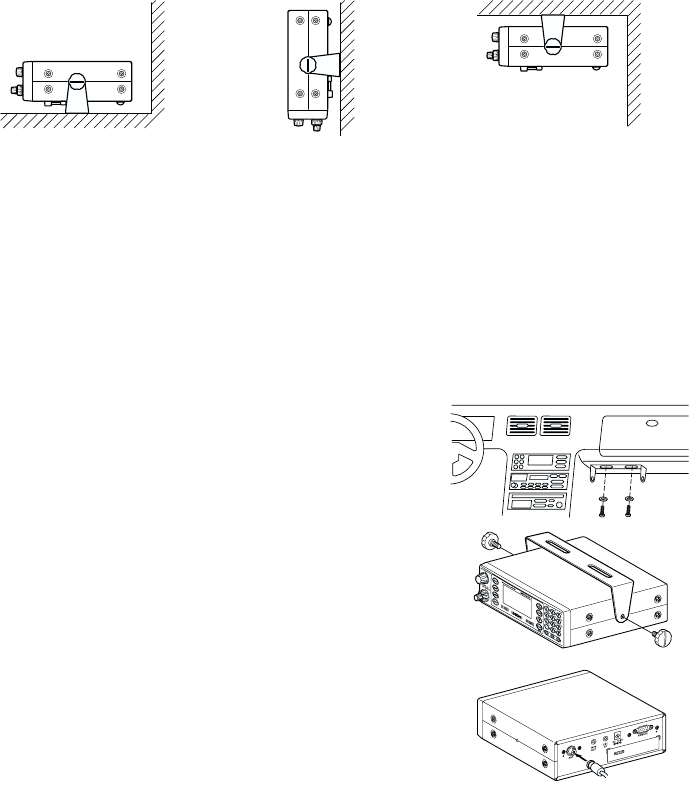
Typical Mounting Methods
The BC780XLT can be conveniently mounted on a table, bulkhead, overhead, or any other
desired location (refer to figure below for typical mounting methods).
Caution: Make sure there are no hidden electrical wires or other items behind the desired
location before proceeding. Check that free access for mounting and cabling
is available.
Mounting the Scanner in Your Vehicle
Before you mount the scanner, make sure you have all the necessary materials. Then
confirm that the scanner fits your vehicle’s mounting area. This unit requires a mounting
area of 2-3/8 inch high by 6-15/16 inch wide by 6-9/16 inch deep (61 x 176.5 x 167 mm).
Caution: Be sure to avoid obstructions behind the mounting surface.
Follow these steps to mount the scanner in your vehicle.
1. Choose a mounting location, then use the supplied
mounting bracket as a template to mark the positions for
the mounting screw holes.
2. In the marked positions, drill holes slightly smaller than
the supplied screws.
3. Attach the mounting bracket to the mounting location
using the supplied screws and lock washers.
4. Attach the scanner to the mounting bracket using the
supplied mounting knobs.
5. Connect the antenna’s cable to the ANT. connector
on the back of the scanner.
Note: If the antenna cable’s connector does not fit in the ANT.
connector, you might also need a Motorola-to BNC
antenna plug adapter (available at a local
electronics store).
•Table top mount •Bulkhead mount •Overhead mount
9
Applying Power for Vehicle Installation
You can power your scanner using either the supplied DC power cord or your vehicle’s
cigarette lighter socket using DC cigarette lighter power cord.
Caution: You must use a power source that supplies 13.8 V DC and delivers at least
700 mA. Your standard 12 V car battery should be sufficient. The cord connector’s
center tip must be set to positive and its plug must fit the scanner’s DC 13.8 V
jack. The supplied DC power cord meets these specifications. Using a power cord
that does not meet these specifications could damage the scanner or the adapter.
•Always connect the adapter or DC power cord to the scanner before you connect it to the
power source. When you finish, disconnect the adapter or DC power cord from the power
source before you disconnect it from the scanner.
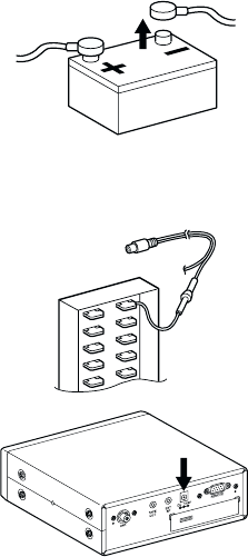
•For added safety and to protect your scanner,
disconnect the cable from your vehicle battery’s
negative (-) terminal before you begin.
Follow these steps to connect the supplied DC power cord.
1. Connect the power cord’s black wire to a chassis ground, such as a metal screw
attached to a metal part of the vehicle’s frame. Be sure that the screw is not insulated
from the frame by a plastic part.
2. Connect the power cord’s red wire (with in-line fuse)
to a source of voltage that turns on and off with the
ignition switch, such as a spare accessory terminal in
your vehicle’s fuse box.
3. Insert the power cord’s barrel plug into the DC 13.8 V
jack on the back of the scanner.
4. Reconnect the cable to the vehicle battery’s
negative (-) terminal.
To power the scanner from a vehicle’s 12 V power source (such as a cigarette-lighter
socket), you need a cigarette-lighter adapter.
To connect an optional DC cigarette-lighter power cable, insert its barrel plug into the
DC 13.8 V jack on the back of the scanner, then plug the power cable into your vehicle’s
cigarette lighter socket.
Note: If you use a cigarette-lighter power cable and your vehicle’s engine is running, you
might hear electrical noise from the engine while scanning. This is normal.
10
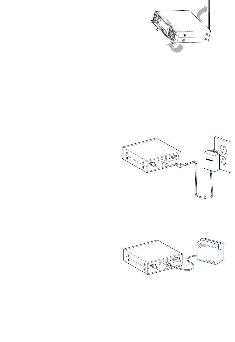
Desktop Installation
You can place this scanner on a desk, shelf, or
table to use it as a base station.
1. Flip up the feet for desk installation.
2. Extend the antenna to full vertical position. Adjust
the angle for best reception.
Applying Power Using Standard AC Power
To power the scanner from an AC outlet, use the provided AC adapter with a 5.5 mm outer
diameter/2.1mm inner diameter tip.
Caution: You must use a Class 2 power source that supplies 13.8 V DC and delivers at
least 700 mA. The cord connector’s center tip must be set to positive and its plug
must fit the scanner’s DC 13.8 V jack. Using an adapter that does not meet these
specifications could damage the scanner or the adapter.
•Always connect the AC adapter to the scanner before you connect it to AC power. When
you finish, disconnect the adapter from the AC power before you disconnect it from
the scanner.
1. Insert the adapter’s barrel plug into the DC
13.8 V jack on the back of the scanner.
2. Plug the adapter into a standard AC outlet.
Note: Use only the AC adapter supplied with
your scanner.
Connecting an External Speaker
In a noisy area, an external speaker (available at a local electronics store) positioned in the
right place might provide more comfortable listening.
Plug the speaker cable’s 1/8 inch (3.5 mm) plug into your scanner’s EXT. SP. jack.
Note: Connecting an external speaker
disconnects the scanner’s
internal speaker.
13.8V
Connecting an Earphone
For private listening, you can connect an earphone with a 1/8 inch (3.5 mm) plug to the
EXT. SP. jack on the back of the scanner. Be very careful as damage to your hearing can
result if the VOLUME control is not set to the lowest level first. See below for "Listening
Safely" instructions. (Your local electronics store should carry a wide selection of earphones.)
Once the earphone is connected, it will automatically disconnects the internal speaker.
11
Listening Safely
To protect your hearing, follow these guidelines when you use an earphone or headphones.
•Do not use the earphone to listen to the WX alert siren test. The volume is not
adjustable and damage to your hearing could occur.
•Do not listen at extremely high volume levels. Extended high volume listening can lead to
permanent hearing loss.
•Set the VOLUME to the lowest setting before you begin listening. After you begin listening,
adjust the VOLUME to a comfortable level.
•Once you set the VOLUME, do not increase it. Over time, your ears adapt to the volume
level, so a volume level that does not cause discomfort might still damage your hearing.
Connecting the Clone Cable
You can transfer the programmed data to and from another BC780XLT scanner using an
RS232C Cable (9 pin to 9 pin) (not supplied). Connect the cable between each scanner’s
REMOTE jacks. See "Clone Mode" on page 60. You can also upload or download the
programmed data to or from a PC using an optional PC interface kit available through your
local electronics store.
Connecting the Tape Recorder
You can use a standard tape recorder or a VOX (Voice Operated Control) recorder. To
connect the recorder to the scanner, connect a cable with a 1/8 inch (3.5 mm) plug from the
tape recorder’s remote jack to the TAPE OUT jack on the back of the scanner. (Your local
electronics store should carry a wide selection of cables and tape recorders.) Refer to the
"Record" section under "Additional Features" in the manual.
Remember!
•You must mark a channel, ID, talkgroup, or bank for Recording in order for this feature to
work. The LINE icon appears on all channels that have been properly marked.
•This feature does not work if your scanner is set with MUTE ON.
•The VOLUME control affects the Audio output. Do not set the volume on minimum. Make
a trial taping to be certain the volume levels are set correctly.
12
Basic Operation
Note: Fold out the Front Cover to see the Controls and Indicators while reading this Guide.
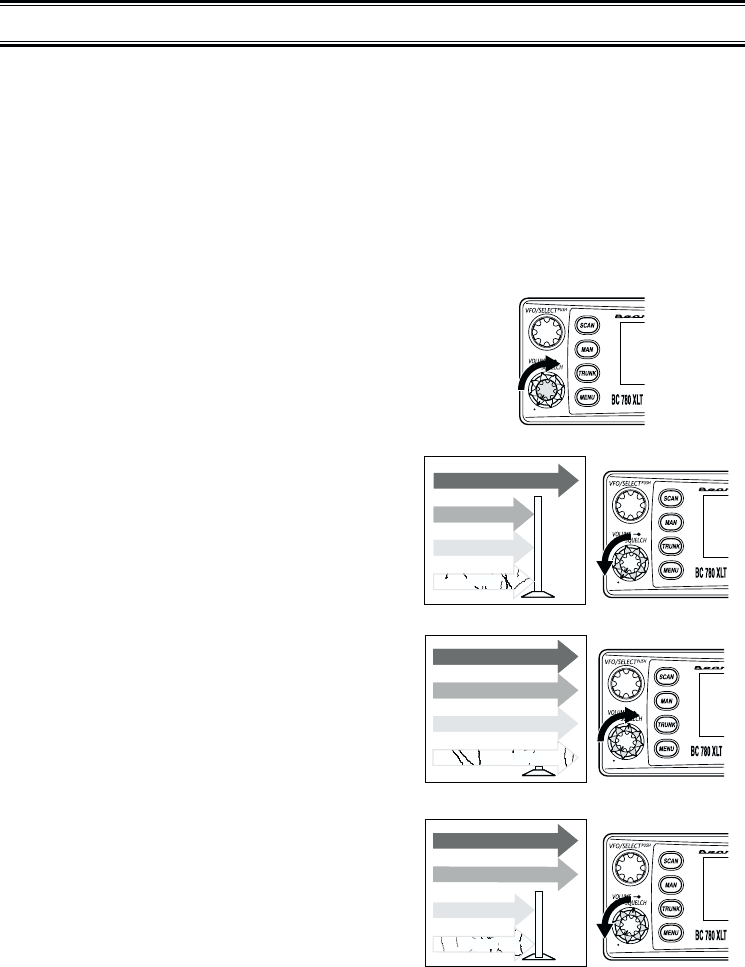
Turn the Scanner On
Turn the VOLUME control clockwise out of the detent position. The scanner automatically
starts scanning. Since there are no frequencies programmed in your scanner initially, you
may not receive any signals. Once you set the squelch and program some frequencies, you
will be hearing conversations regularly.
Setting the Squelch
To set the squelch, you must be in the Manual mode, and you
should not be receiving a signal on your scanner.
1. Press MAN until you do not hear a signal.
2. Make sure that the VOLUME is set to a
comfortable listening level.
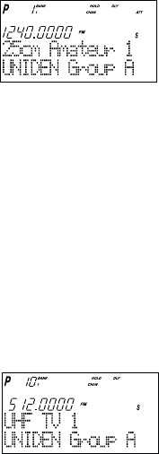
3. Think of the Squelch Control as a gate. Turn
SQUELCH fully counter-clockwise. This raises
the "Squelch Gate" so high that only very
strong signals can get through.
4. Turn SQUELCH fully clockwise until you hear
a hiss. This lowers the "Squelch Gate" so that
everything gets through – noise, weak signals,
and strong signals.
5. Turn SQUELCH back counter-clockwise just
until the hiss stops. Now the "Squelch Gate"
allows only clear signals through.
Next you must program some frequencies. (Page 20) It is recommended that you read the
next part "Understanding the Menu System" because it will assist you in accessing and
understanding many of the features. Later in a section called "Additional Features", you will
find explanations on how to disable the keypad acknowledgement tones, how to mute the
audio, how to change the appearance of the display and other general features.
STRONG SIGNALS
MEDIUM SIGNALS
WEAK SIGNALS
NOISE
STRONG SIGNALS
MEDIUM SIGNALS
WEAK SIGNALS
NOISE
STRONG SIGNALS
MEDIUM SIGNALS
WEAK SIGNALS
NOISE
13
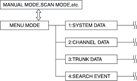
Understanding the Menu System
It is very important for you to understand the Menu screen. To navigate through the Menu
screen is really quite simple. Many of the features of this scanner, can only be accessed by
the menu screens. There are several ways to get through the screens. First of all, press
MENU to get started. Any time you want to exit this mode or simply quit from where you are,
repeatedly press MENU until the scanner returns to the original state. Anytime you are in the
Menu Mode, the audio will be muted.
To assist you in understanding the Menu screen, flow charts are provided towards the back
of the manual so you can follow along. Two things to remember are scroll through the menu
and execute the command. For simplicity, we have chosen to use the up and down arrow
keys (▲and ▼) in order to scroll through the menu and the Ekey for entering or executing a
command. Once you have pressed the Ekey and executed the final choice (for instance,
ON or OFF), the display backs up to the previous level of options.
Other methods for scrolling through the menu screen include rotating the VFO control or
press and hold the up and down arrow keys (▲and ▼) in order to scroll more quickly. Also
direct entry of the numbers in the flow chart will get you through the screens, but the other
screen options are not visible. This method should be used only after you have gone
through the manual at least once. A tearout shortcut card is provided in the front of the
manual to assist you in the direct entry method for commonly used features.
Another method for entering or executing the command, press the SELECT/MUTE key or
press the VFO/SELECT control.
Below is the first level of the Menu screen. These levels are then expanded on the foldout
towards the back of the manual. You will find a description section to explain the meanings
of these functions on the next few pages. Then, you will be walked through all the steps of
programming, scanning, searching, and trunktracking.
14
Menu Description and Numeric Keypad Equivalents
Below are the menu screens and a brief description or purpose of the feature.
1:SYSTEM DATA
1:DIMMER
Allows you to change the brightness of the display.
2:SCREEN MASK
Screen Mask allows you to limit what appears on the display to the alpha tags that
you have set for a channel along with a few function icons. Screen Mask removes
the frequency, receiving mode, tone data, signal strength bars, and the trunking
repeater activity indicators. This mode is particularly useful in public safety vehicles
where "information overload" is already a problem. Screen Mask does not work in
Search mode.
3:KEY BEEP
Use this function to turn off the keypad acknowledgement beep. The default setting
is on.
4:ENTER LOCK
Use Enter Lock to prevent accidental re-programming of channels and talkgroups
entered into memory. The default setting is off.
5:PC CONTROL
Use this function to set the transfer speed (baud rate) at which your personal
computer (PC) communicates with the scanner when downloading information into
your scanner using the Uniden national database or third party software. See page
59 for details.
6:CLONE
You can clone all the programming, including frequencies, talkgroups and alpha tags
as well as bank settings and other parameters from one BC780XLT to another.
7:DATA SKIP
A scanner will normally stop on any transmission it receives. This means the
BC780XLT will occasionally stop on data signals and unmodulated transmissions.
You can automatically skip many of these types of transmissions during search.
8:SQUELCH MODE
The Squelch Mode allows you to set, at your option, whether the scanner will stop
on all active transmissions on a particular frequency or it will only respond to
transmissions with a pre-set sub-audible tone. This applies to both conventional
search and scan modes.The options are as follows:
1. CSQ - The default setting is CSQ (carrier squelch). In this mode the scanner will
stop on any transmission on a programmed frequency (Squelch mode does not
apply to trunking).
2. Tone SQ - In Tone Squelch mode, if you have set a subaudible tone (CTCSS or
DCS) for a frequency, the scanner will only stop on that frequency if the
transmission includes the prescribed tone.

15
3. Tone Search - In this mode, as soon as the scanner stops on any (non-trunked)
channel, the scanner will begin to search for any subaudible tone that is being
used on a transmitted frequency. The scanner will check each CTCSS tone
sequentially and it will find DCS tones instantly.
9:BANK TAG
Allows you to set an alphanumeric text tag for individual banks in the scanner
(1-10).(The "0" key represents Bank number 10.) For example, you may wish to set
the Bank One text tag as Law Enforcement, the second bank as Fire, etc.
2:CHANNEL DATA
Choose the channel number. The following options are available for the selected
channel only. Repeat using a different channel number, if necessary.
1:ALPHA TAG
Allows you to set an alphanumeric text tag for individual frequencies that you have
programmed. For example, you can set DAVIS PD CH #3.
2:DELAY
The default delay for all programmed channels and talkgroups is two seconds. At
the end of any transmission the scanner will remain on the frequency for two
seconds before resuming scanning. This will allow you to catch most replies. You
can change the delay to 1, or 4 seconds as well as set no delay (the scanner will
immediately resume scanning after the end of a transmission). With the BC780XLT
you can also set negative or inverse delays, also known as Pause. With a 5 second
pause, for example, the scanner will resume scanning after five seconds even if the
transmission you are currently listening to has not ended. Finally, you can set an
Infinite Delay. If a transmission is received on a frequency with Infinite delay set, the
scanner will stop on the channel and remain on it until you have hit scan,
search, etc.
3:TONE DATA
You can set a CTCSS (analog) or DCS (digital) sub-audible tone for a frequency. To
do so you must have the Squelch Mode in the System Menu set to Tone Squelch.
You can also program a subaudible tone easily by pressing the E(enter) key after
programming a frequency. This will bring up the Tone Data menu without your
having to navigate the Menu. You can also lock a tone assigned to a frequency. By
doing this you will receive all transmissions on the frequency, regardless of the
subaudible tone, except the one which you have locked. Any transmissions with that
tone will not be received.
4:BEEP ALERT
You can set a Beep Alert on a per-channel basis to alert you when specific
frequencies are active. For example, you may wish to be alerted anytime a mutual
aid fire frequency is active. With beep alert, you will hear a rapid three-beep tone at
the start of each transmission that you have flagged as such. You will also notice
that as you scroll pass the flagged channel(s), you will hear the tones.
5:ATTENUATOR
The BC780XLT comes with an RF Attenuation feature. If you are near an unusually
strong signal source, the signal may overload the scanner. The scanner may stop
repeatedly on that signal and miss other transmissions.
The RF Attenuation feature works in all modes and attenuates (reduces) the
incoming signal strength to prevent stronger signals from overloading the scanner.

16
6:STEPS
Your BC780XLT is programmed with default step sizes for each frequency range
(see inside front cover). Steps are important if you are interested in using the VFO
to tune off-frequency from a frequency programmed into memory or if you wish to
program a frequency that the default step size will not accept. For example, in VHF
Hi-band mode, the default step size between 148 and 162 MHz is 5 KHz. However,
the FCC has recently instituted 7.5 KHz channel intervals. If you wish to enter
155.4075 into the scanner without changing the default step, the scanner will
change the programmed frequency to 155.4100. Use the menu to change the
default step size to 7.5 KHz and then you will be able to enter 155.4075.
7:MODE
Default receive modes are also programmed into memory. AM for the aircraft and
CB bands, for example. All frequencies (other than TV broadcast audio) above 400
MHz are received in NFM mode which helps prevent adjacent channel interference.
You can change the default settings on a per-channel basis with this Menu item.
8:RECORD
You can flag any channel for recording using this menu function. The LINE icon will
become active for any such flagged channel. Use your own recording device
plugged into the jack on the back of the scanner.
3:TRUNK DATA
Choose the Trunk bank. The following options are available for the selected trunk
bank only. Repeat using a different trunk bank, if necessary.
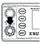
1:TRUNK TYPE
You will need to assign the correct trunking type for the bank you are about to
program. If you want to listen to a Motorola Type 1 system, you will need to use this
menu option to assign the same. If you do not know the type of trunking system
you are about to monitor, refer to the guide included with the radio or check out
www.trunktracker.com.
Note: Some trunking systems require that you know the channel order. In these
cases you will also need to start programming the trunked system at the
start of the bank. The scanner defaults to the most common type of
trunking system, Motorola Type II.
2:DELAY
You can set delay for a trunk system on a bank by bank basis. If you’ve set delay
for 1 second, then there will be a one second delay in Trunk Search for that bank
and a one second delay for all the talkgroups you have programmed into Scan List
memory. You cannot set delay individually by talkgroup. The default delay is
two seconds.
3:RECORD
This Record option applies to Trunk Search. If you have set Record on, the LINE
icon will be lit. All talkgroups received during Trunk Search will be recordable
through the TAPE OUT jack on the back of the scanner. To record individual
talkgroups during Scan, see Item 5 on the next page. The default is off.

17
4:L/O ID REVIEW
Use this menu item to review the IDs that you have locked out during Search and
Scan. Use the Up/Down arrow keys or turn the VFO to the left or right to view the
IDs that have been locked out. To leave the lockout IDs unchanged, press MENU to
back out of the menu. To unlock an ID, press the L/O key. To unlock all the IDs that
have been locked out, press the E (Enter) key.
5:PROGRAM ID
You can program IDs into Scan List memory either during Trunk Scan or Search
without going into the Menu. However, you can also use the Menu to program IDs.
This is particularly helpful when you are not near the trunked system you wish to
later monitor. You can set it up and have it ready to go at some later time.
After you have selected the Scan List location (1-10) and the memory location
(1-10), you can then do the following:
1Program the talkgroup or I-CALL ID number
2Set an alpha tag for same
3Assign the Record option for same. Whenever a transmission is active on
the ID the signal can be recorded to a tape recorder using the TAPE OUT
jack on the back of the radio.
4.Assign a Beep Alert to the ID. Whenever that ID is active, you will hear a
rapid three beep tone at the start of the transmission.
6:ID LIST TAG
Assign an alphanumeric tag to any or all of the 10 Scan Lists for the system. During
Scan Mode, you will see the List Tag (on the bottom text line) along with any alpha
tag you may have set for an ID. In Search mode, you will see any Bank Tag you
have set.
7:I-CALL (MOTOROLA AND EDCS)
Most communications within a trunked system are group calls where one unit (such
as a dispatcher) communicates with all the units within his/her group (all the patrol
vehicles on the east side of town, for example). The units within this group comprise
what is typically known as a talkgroup. There are some communications which are
direct unit-to-unit conversations where one individual converses with another
individual. The call is initiated by a radio and is directed to another single radio.
Within the system, no one outside of these two users hears the conversation.
Your BC780XLT defaults to I-CALL OFF mode. You can hear these conversations
by using this Menu item to turn the I-CALL function to ON. In Search mode, with
I-CALL on, you will hear both talkgroup calls and I-CALLs. You can also set I-CALLs
to I-CALL ONLY during which you will monitor only I-CALLs in Search mode. You
can also program I-CALL IDs into Scan List memory.
OR
7:ID SCAN LIST (LT)
When scanning an LT system you can only turn Scan Lists off and on when an LT
talk group that you have entered into memory is active. To provide you with another
method to turn Scan Lists on and off, you can use this Menu item which only
appears when you have selected LT in Trunk Type.

18
8:STATUS BIT (MOTOROLA)
On Type II trunking systems there is a method by which specialized types of
communications utilize unique talkgroup numbers. An emergency call will occur on
a unique talkgroup from its primary assignment, for example. Because the
BC780XLT defaults to Status-Bit On mode, you never need to worry about missing
these transmissions. If you've programmed talkgroup 33264 into Scan List memory,
for example, and there is an emergency call within the group, you will hear it on
33264.
OR
8:EDACS ID FORM (EDCS)
You can change to display the talkgroups in decimal mode, but this mode does not
provide you with nearly the flexibility that you get with AFS. The BC780XLT defaults
to show the talkgroup number in AFS mode (Agency-Fleet-Subfleet). For details on
AFS see pages 50-51.
9:END CODE (MOTOROLA)
When this function is disabled, the radio looks for squelch before returning to the
control channel instead of waiting for the disconnect tone. Only in rare instances
will you need to adjust the default settings.
The condition to return to control channels depends on whether signal is present
or not.
0:CONTROL CH ONLY (MOTOROLA 800 & 900 SYSTEMS)
With this mode you will be able to track Motorola Type I and II 800 and 900 MHz
trunked systems by simply entering the control channel which manages the trunked
system. You will not have to program the voice channels. There are 4 channel plans
which you can select from.
4:SEARCH EVENT
You can program up to 10 search ranges (one per bank). The first time you
program a range for a bank you will need to do so through the Menu. After the first
time you can program a range as you do on most any other scanner, using the
numeric keypad and the ▲/ HOLD or ▼/ LIMIT keys.
1:SEARCH BANK
Use this Menu item to select the search bank that you want to program. You can
program banks 1 through 10, one at a time. For each of the banks, the following
options can be modified.
1:EDIT RANGE
Enter the upper and lower frequency limits of the search range.
2:STEPS
You can assign a variety of step sizes to the search range. Note: The
default step is usually acceptable and is listed in the front of the manual.
(See inside front cover)
3:MODE
You can change the default receive mode with this menu item.
4:ALPHA TAG
You can alpha tag any or all of the search banks.

19
2:DELAY
Set a delay for the search ranges. This applies to all ranges (See CHANNEL DATA-
STEPS for details).
3:ATTENUATOR
Set attenuation for all search ranges. (See CHANNEL DATA-ATTENUATOR
for details).
4:TONE DATA
The default mode is off. This means that you will receive all transmissions on any
frequencies that are active within your search range(s). By selecting CTCSS or
DCS you can set the radio to receive only a particular subaudible tone to be
received during your search. You can also lockout a particular CTCSS or DCS tone.
You may wish to do this if you want to search a range but not hear transmissions
on any frequency that have particular subaudible tone.
Note: Through the System Menu you can set the radio to operate in Tone Search
mode during Search as well. In this mode, the radio will automatically determine the
active subaudible tone on any frequency received during the Search.
5:RECORD
With Record set to on, any frequency that is active, during the search, can be
recorded to an external tape recorder.
6:AUTO STORE
You can automatically store active frequencies found during a search into memory.
You can select which bank you want to program the found frequencies. Note that
the audio will be muted during Auto Store.
20
Programming
Before the BC780XLT can begin conventional scanning, you must program a frequency into
at least one channel. Repeat this procedure for each channel you want to program.
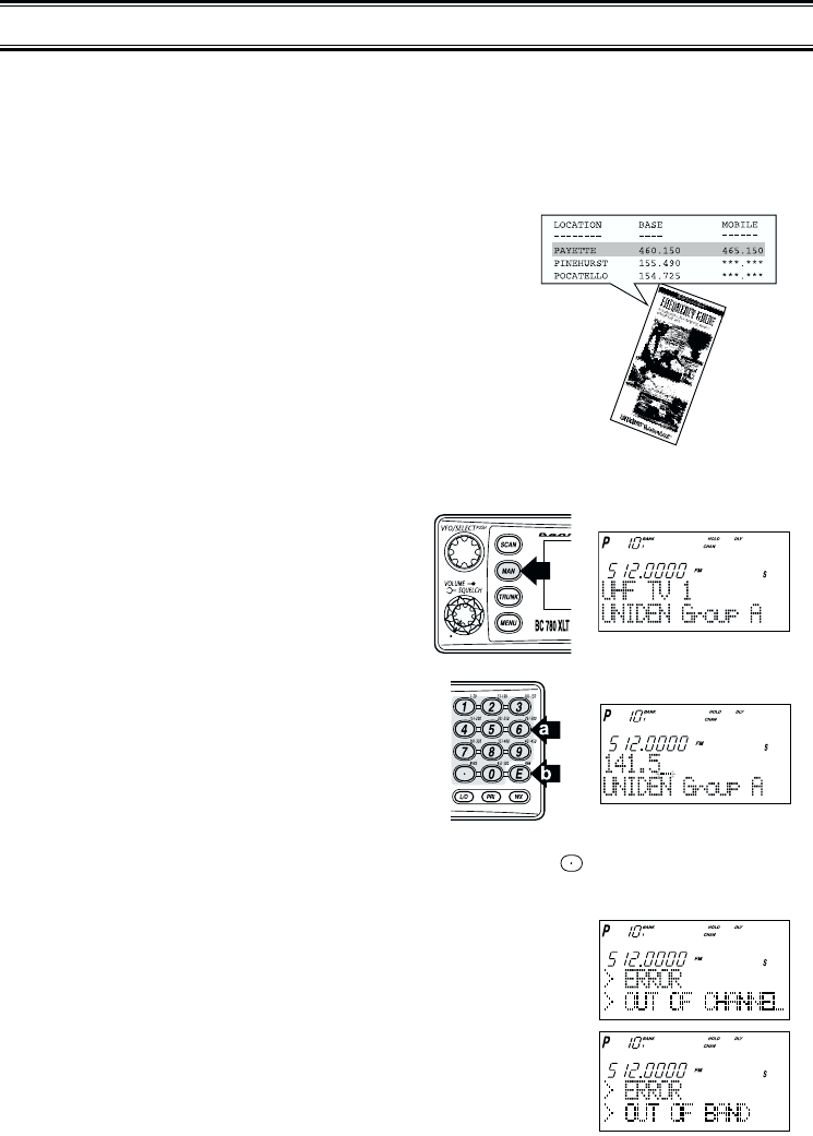
Storing Frequencies into Channels
1. Select frequencies from your dealer, from
various sources on the internet, or from one of
the guides listed on page 5.
Here is a list of sample frequencies you should try:
156.800 Marine Calling channel
155.340 Ambulance operations
155.280 Ambulance operations
155.160 Ambulance operations
462.950 Ambulance operations
462.5625 Family Radio Services (channel one)
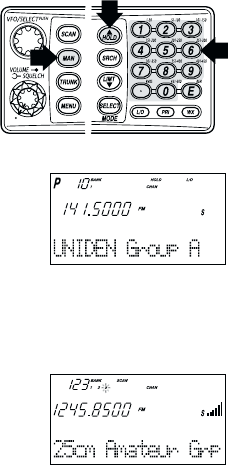
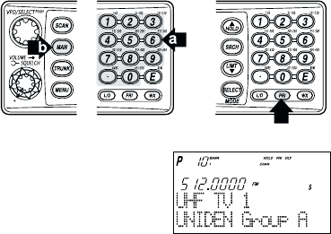
2. Press MAN.
3. Select a channel.
a. Enter the channel number.
b. Then press MAN.
4. Enter the frequency.
a. Enter the frequency number.
b. Then press E.
Note: •To clear a mistake while entering the frequency, press (decimal key) repeatedly
until the display is cleared.
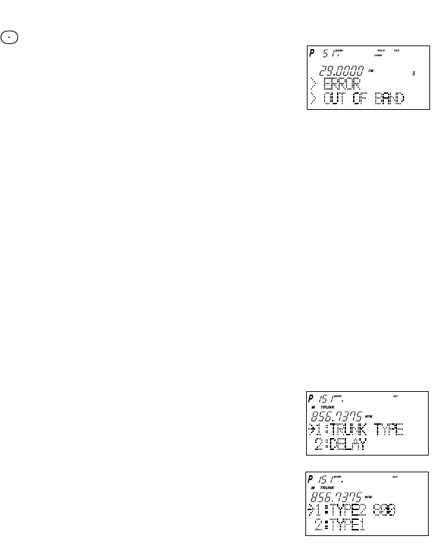
•If you enter a channel or frequency which is out
of the scanner’s range, a distinctive beep will
sound and ERROR appears in the display.
•You can use ▲or ▼when selecting a channel.
Press and hold ▲or ▼for 1 second to move up/down more quickly.
21
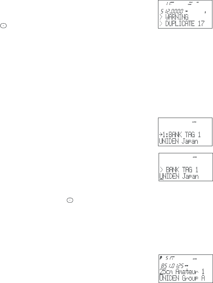
Duplicate Frequency Alert
If you enter a frequency which has been stored in
another channel, you will hear a beep and the other
channel displays WARNING.
Press to clear and start again.
––– OR –––
Press Eagain to store the frequency in both channels.
Storing Text Tags
You can customize your scanner by storing text tags for easy identification of banks, channel
transmissions, trunking talkgroup IDs, etc. The text tags can be set at the menu mode.
(Refer to Understanding Menu System on page 13.)
Assigning a Bank Tag to a Bank
1. Press MENU.
2. Press Eto select SYSTEM DATA.
3. Press ▲or ▼to select BANK TAG and then press E.
4. Select the bank number to be tagged using ▲or ▼
and then press E.
5. The cursor appears on the display. Rotate VFO to change
letters, and then press ▲or ▼to shift right or left. Both
capital and lower case letters are available, as well as
numbers and punctuation marks.
6. After entering the desired text, press Eor SELECT.
☞Remember! You can also use the VFO control for scrolling. To clear a mistake while
entering the frequency, press (decimal key) repeatedly until the display is cleared.
Assigning a Text Tag to a Channel
1. Press MENU.
2. Press ▲or ▼to select CH DATA and then press E.
3. Select the channel number to be tagged using ▲or ▼and pressing E. You can also
enter the channel number in using the keypad and then press E.
4. Press ▲or ▼to select ALPHA TAG and then pressing E.
Note:•If you have not stored a frequency in the channel,
UNREGISTERED will appear in the display.
5. The cursor appears on the display. Rotate VFO to
change letters, and press ▲or ▼to shift right or left.
Both capital and lower case letters are available, as
well as numbers and punctuation marks.
6. After entering the desired text, press E, SELECT or VFO.

22
Beep Alert
The scanner can alert you with three rapid beeps at the beginning of a transmission on an
assigned frequency.
Assigning the beep alert to a channel
This alert can be set on/off to every channel (or to every ID memory for Trunking mode).
1. Press MENU.
2. Press ▲or ▼to select CH DATA and then press E.
3. Select the channel number to be tagged using ▲or ▼and then press E. (You can also
enter the channel number in using the keypad or VFO control and then press E.)
4. Press ▲or ▼to select BEEP ALERT and then press E.
5. Press ▲or ▼to select ON or OFF and then pressing E.
Note: If NOT REGISTER appears, make sure a frequency is stored in the channel.
Programming Tips
•Do not program a weather frequency into one of the channels, since weather channels
transmit continuously. Use the Weather Search feature to select the weather information band.
•Group similar services into a bank. For example, program police frequencies in channels 1
through 10 and fire/emergency into channels 51 through 60, and so on.
•Put the frequency that you listen to the most or the most important frequency into a
Priority channel.
•To quickly program a series of channels, start with the lowest number channel.
For example, when you are programming five new frequencies into Channels 4 through
8, start with Channel 4. After you finish programming a channel, press MAN or HOLD/▲
to go to the next higher channel.
•Write down your programmed channels and frequencies and put in a convenient place in
case of accidental reprogramming.
•Frequencies are rounded off according to the step of each channel.
•When you are overwriting a tagged channel with a new frequency, the previous alpha tag
will be deleted. You must re-enter the alpha tag.
•When programming frequencies, a 2 second delay is set automatically but can be
changed in the Channel Data menu.
Deleting a Stored Frequency
To delete a stored frequency:
a. Select a channel.
b. Press 0.
c. Then press E.
Note: Channels with no frequencies are automatically locked out.
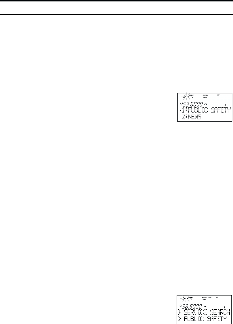
SERVICE SEARCH
PUBLIC SAFETY
23
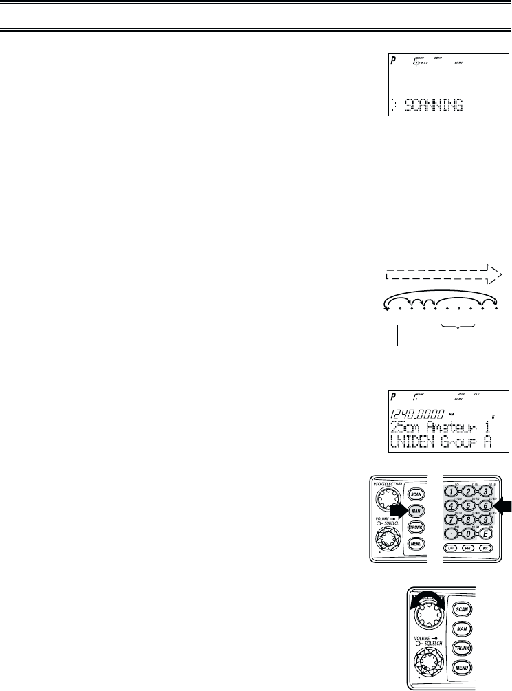
1. After programming frequencies, simply press SCAN to
begin scanning.
2. The bank indicators selected for scanning appear in the display, and the bank being
currently monitored flashes. You can deselect banks from active scanning by pressing
their number on your keypad. The indicator for each deselected bank turns off, and the
banks channels are not scanned.
Note: One Bank must always be active. You cannot deactivate all ten banks at the same
time. If you try to turn off all the banks, the first bank is automatically selected.
To restore a bank to active scanning, press the banks number on your keypad.
The banks indicator will display again.
3. During normal scanning the scanner skips
unprogrammed or locked out channels.
4. When a transmission is received, the scanner stops
on that channel. When the transmission ends, scanning
resumes automatically.
If you want to stop on a channel during scanning,
press MAN.
If you want to resume scanning, press SCAN.
To directly access a specific channel:
There are several ways to access a specific channel quickly.
1. Press MAN.
2. Using the keypad, enter the channel number.
3. Press MAN again.
Another method is as follows:
1. Press the VFO control until CHAN is displayed.
2. Rotate the VFO control until the desired channel is
displayed. The scanner will automatically go to
manual mode.
Note: You can accidentally change the frequency if you don’t
verify that CHAN is displayed. If FREQ is displayed, you
will be changing the frequency when you rotate the
VFO control. Just don’t press Eor it will be changed!
Scanning
1345
9 10
26
7 8
CHANNELS
Frequency
not entered
Frequency
Locked Out
(L/O)
SCAN
24
Still another method of direct access to a specific channel:
1. Press MAN.
2. Press ▲or ▼to select the channel. (or press and hold ▲or ▼to scroll more quickly.)
Lastly to step up through the channels one at a time, repeatedly press MAN.
RF Attenuation Feature
The BC 780XLT comes with an RF Attenuation feature. If you're near an unusually strong
signal source, the signal may overload the scanner. The scanner may stop repeatedly on
that signal and miss other transmissions.
The RF Attenuation feature works in all modes and attenuates (reduces) the incoming signal
strength to prevent stronger signals from overloading the scanner.
The RF attenuation is set at the menu mode.
1. Press MENU.
2. For Search mode, press ▲or ▼to select SEARCH
EVENT and then press E.
OR
For Scan mode, press ▲or ▼to select CH DATA
and then press E. Then you must enter your channel
data by pressing s , t or direct keypad entry. Then
press E.
3. Press ▲or ▼to select ATTENUATOR and then
press E.
4. Set to ON using ▲or ▼and then press E.
ATT appears on the display.
☞Remember! You can also use the VFO control for scrolling. Also instead of pressing E,
you can press the VFO/SELECT control or press the SELECT/MUTE key.
Note: Attenuation will only be active for the specified channel. In SEARCH mode, it is
applied to the search ranges in all banks.
Setting the Delay Mode
A default delay of 2 seconds is automatically set for each frequency or talkgroup. A different
delay can be set for each programmed channel so that when scan or search stops on a
channel there is a brief pause before the scanning cycle resumes. To set the delay feature,
enter into the menu mode.
1. Press MENU.
2. Press ▲or ▼to select CH DATA and then press E.
3. Select the channel number to be delayed using ▲or ▼and
then press E.
4. Press ▲or ▼to select DELAY and then press E.
25
5. Press s or t to select one of the delay periods provided and then press E.
DLY appears on the display unless no delay has been set.
6. For Search mode, select SEARCH EVENT - DELAY, then set the delay period.
Note: The delay periods are as follows:
• None: Delay feature off
• 1 sec.: Delays for 1 sec. before re-scanning
• 2 sec.: Delays for 2 sec. before re-scanning
• 4 sec.: Delays for 4 sec. before re-scanning
• Infinite: Stays on until SCAN is pressed
• -2 sec.: Stays for 2 sec. only before re-scanning *
• -5 sec.: Stays for 5 sec. only before re-scanning *
• -10 sec.: Stays for 10 sec. only before re-scanning *
* Setting negative delay periods are useful if you are only interested in small
segments of conversations. For example: If you set a -5 second delay, you will only
hear 5 seconds of the conversation and then the scanner will resume scanning,
whether or not the conversation is finished.
Channel Lockout
You can lockout any channel so it is not checked during normal scanning. You can restore
the channel to scanning when you wish.
Lockout in Manual Mode
1. Press MAN.
2. Select a channel.
Enter the channel numbers.
Press MAN again.
––– OR –––
Press MAN or HOLD/▲to change higher,
or LIMIT/▼to lower the channel.
3. Press L/O to lockout the channel.
L/O appears in the display.
Lockout in Scanning Mode
If the scanner keeps stopping on a particular channel due to noise or too frequent
transmissions, you may want to keep that channel from scanning.
1. Wait until the scanner stops at the channel.
2. Then press L/O.
26
3. The scanner immediately resumes scanning because the locked
out channel is no longer in the scanning sequence.
Lockout Tips • Write down your locked-out channels and put in a convenient place in
case you need to restore them.
Restoring a Locked-out Channel
1. Press MAN.
2. Select a locked out channel.
a. Enter the channel number.
b. Then press MAN again.
3. Press L/O to unlock the channel. The L/O icon goes out.
Restoring All Locked-out Channels
You can restore all locked-out channels in a bank only when a bank is selected for scan. If
you have deselected a bank and you want to restore all of its locked-out channels using the
steps below, you must press SCAN and then press the number of the bank on your keypad.
1. Press MAN.
Note: You must be in Manual mode before restoring all
locked-out channels.
2. Press and hold L/O for about two seconds.
You will hear two beeps when all the channels have
been restored.
Priority Scan
When Priority Scan is turned on, your scanner checks the priority channel every two
seconds for activity. If a signal is present on the priority channel, your scanner monitors the
channel until the transmission ends, then resumes normal scanning. You can designate one
channel in each bank as a Priority Channel. By default, the first channel in each bank is the
priority channel, but you can change this.
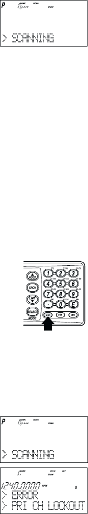
To activate Priority Scan (in either the Manual or Scan Mode):
1. Press PRI.
Note: If you have locked out the priority channel, ERROR
message appears when you select Priority mode.
2. Press PRI again at anytime to deactivate Priority Scan.
27
Changing the Priority Channel
You cannot eliminate the Priority Channel, but you can change it to any one of the 50
available channels in each bank.
1. Press MAN.
2. To select a new Priority Channel:
a. Enter the channel number.
b. Then press MAN again.
3. Press and hold PRI for two seconds to designate this
channel as your new Priority Channel.
Two beeps indicate that the Priority
channel has been changed. The Picon appears in
the display.
Note:•Priority in Trunking mode works just the same, except instead of setting priorities
for channels, you set them for talkgroup IDs. The scanner only checks priority
talkgroups between transmission, not in 2 second intervals.
•Priority scan is disabled while the TRUNK icon is lit (an error tone will sound
if you try). To make it possible, turn off the TRUNK icon then press PRI.
•At Priority scan, it scans the designated Priority Channels in the banks
you selected.

28
Searching
Setting a Search Range
Note: First you must set the search ranges through the menu screen prior to any searching.
The BC780XLT can search up to 10 separate frequency ranges to help you discover new
stations in your area.
To set a search range, enter into the menu mode.
1. Press MENU.
2. Press ▲or ▼to select SEARCH EVENT and then press E.
3. Press ▲or ▼to select SEARCH BANK and then press E.
4. Press ▲or ▼to select the desired bank number and then press E.
5. Press ▲or ▼to select EDIT RANGE and then press E.
6. Enter the lowest frequency using the keypad and then
press E, then repeat the same for the highest frequency.
Then press SRCH.
Note:•The scanner can search up to 10 ranges by selecting specific banks which you
have programmed search ranges. (Chain Search)
•You can select or deselect the search bank freely by pressing the corresponding
number with the keypad.
•The scanner automatically increases its search speed from 100 to 300 steps per
second for the bands having 5 kHz steps. (Turbo Search)
•Press and hold ▲or ▼for more than 2 seconds while searching to switch the
search direction.
•When searching in WFM, it stops before reaching the desired frequency if the step
is other than 50 kHz or 100 kHz.
•After you have set the Search Range through the Menu the first time for a bank,
you will be able to set new ranges for the same bank by using the keypad and the
standard direct entry method.
Note: After you have entered the search range in a selected bank while still in the menu
mode, you can set your alpha tag (see page 21), change the step size of the search,
or change the mode. Once the lower and upper parameters of your search are
edited, the menu screen backs up one level to allow you to modify the step size,
receive mode, and alpha tag. Select 2: STEPS for your step size choices and then
press E. Select 3: MODE for the receiver mode choices and then press E.
Select 4: ALPHA TAG to enter an alpha tag using the VFO control.
29
Search Hold Feature
1. Press HOLD/▲at anytime to stop the search.
2. Press HOLD/▲to move to the next higher frequency.
––– OR –––
Press LIMIT/▼to move down to the previous frequency.
3. Press SRCH to resume searching.
Data Skip
A scanner will normally stop on any transmission it receives. This means the BC780XLT will
occasionally stop on data signals and unmodulated transmissions. You can automatically
skip many of these types of transmissions during search. To activate the data skip feature,
enter into the menu mode.
1. Press MENU.
2. Press ▲or ▼to select SYSTEM DATA and then press E.
3. Press ▲or ▼to select DATA SKIP and then press E.
4. Set to ON using ▲, ▼or VFO and then press E.
DATA appears on the display.
When data skip is active, your scanner may pause momentarily on an unwanted signal but
will resume searching in 2 or 3 seconds. Data Skip does not function during AM/WFM band
scan, chain search, or WX search, Priority Scan, and Trunking Mode.
Frequency Skip
If a particular frequency continues to interrupt search scanning, it is possible to set your
scanner to skip the frequency.
To skip over a frequency, press L/O when stopping at the frequency you want
to skip.
Note:•You can program up to 200 skip frequencies.
The 201st skip frequency entered causes the
first skipped frequency to unlock.
•If all frequencies in the search range are set to
skip, it moves to Search hold mode.
To resume searching, do as follows:
1) Cancel the frequency skip set, or
2) Reset the search frequency range.
To cancel all skipped frequencies, press and hold L/O for 2 seconds.
30
Storing Search Frequencies
You can quickly store any frequency you find during Search.
Caution: You must select the channel in which you will store the frequency before entering
the search mode. Otherwise, you may erase a stored frequency that you want
to keep.
1. During search, press HOLD/▲when the scanner stops at the
frequency you want to store.
2. Press Eto store the frequency in the channel you selected.
Note:•If the frequency you want to store exists already, WARNING appears on the
display with a beep. (See Duplicate Frequency Alert on page 21.)
•After storing the frequency, it moves to the manual mode.
3. To store another frequency, select another channel for the new frequency by pressing
MAN or HOLD/▲or LIMIT/▼.
4. Repeat steps 1 and 2 after starting search for all the Search frequencies you want to
store.
Auto Storing
The scanner automatically stores searched frequencies if its auto store feature is activated.
To make use of this feature, set a search range first (see page 28), then enter into the menu
mode.
1. Press MENU.
2. Press ▲or ▼to select SEARCH EVENT and then press E.
3. Press ▲or ▼to select AUTO STORE and then press E.
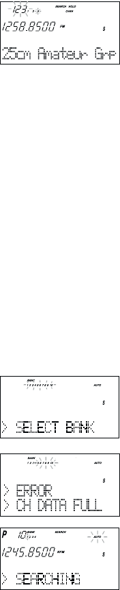
4. Set to ON using ▲, ▼or VFO and pressing E. All bank numbers
start flashing and AUTO is lit on the display.
5. Select the bank numbers you want to use with the keypad. The
selected bank numbers stop flashing.
Note: If the selected bank has no free channels to store,
ERROR will appear on the display with a beep.
6. Press SRCH to start auto storing. The AUTO icon on the display
begins to flash. Audio is muted during the storing process.
7. After the search has gone through the search
range, press MAN or MENU to stop this feature.
STORE END appears in the display. You may
want to let it run through the search range again
because during the first pass there may not be
any transmissions at that particular time.
☞Remember! You can also use the VFO control for scrolling. Also instead of pressing E,
you can press the VFO/SELECT control or press the SELECT/MUTE key.
31
Squelch (SQ) Mode
The scanner can be set to the following SQ modes.
•Carrier SQ mode (default setting)
The scanner will stop on any transmission or squelch opening, regardless of whether any
sub-audible tone has been programmed for the channel or search range.
•Tone SQ mode
The scanner will stop on any active frequency for which either no sub-audible tone has
been programmed or for which the user-programmed sub-audible tone is also active.
•Tone Search mode
During any transmission, the scanner will begin searching all possible sub-audible tones,
one of which may also be in use. The scanner counts up through the CTCSS tones and
instantly determines any possible DCS tone. See Page 77 for a listing of the tones that the
BC780XLT decodes.
Note: When Tone Search is active in Scan Mode, once the CTCSS/DCS display flashes a
tone repeatedly (meaning that it has found the tone match), you can press Eto
program that frequency with the captured tone. When you change the mode to
Tone Squelch from Tone Search, that frequency and tone will be programmed.
•Tone Lock (out) mode
For either a memory channel or a search range, you can lock a particular sub-audible tone
by pressing L/O after scrolling to the desired tone. The scanner will stop on any
transmission except those which may be using the locked sub-audible.
To set your scanner, enter into the menu mode.
1. Press MENU.
2. Press ▲or ▼to select SYSTEM DATA and then press E.
3. Press ▲or ▼to select SQ MODE and then press E.
4. Press ▲or ▼to select one type (CSQ, Tone SQ, Tone Search) and then press E.
5. To set Tone Lock mode, do the following first, then select Tone SQ in step 4.
1) For scan mode, enter CH DATA - CH No. - TONE DATA, select CTCSS/DCS with
▲or ▼, set Tone Lock ON by pressing L/O.
2) For search mode, enter SEARCH EVENT - TONE DATA, select CTCSS/DCS with
▲or ▼, set Tone Lock ON by pressing L/O.
32
Note:•CTCSS: Continuous Tone Coded Squelch System.
•DCS: Digital Coded Squelch.
•For example, the scanner shows the following displays.
•If the delay feature (-2 sec/-5 sec/-10 sec) has been set while in Tone search
mode, it resumes scanning according to the delay setting.
Additional Menu Options for Searching
Each of these additional menu options apply to all banks with search ranges entered. If
there is a bank that you do not want an option to apply, then simply press the bank number
on the numerical keypad. You will see the bank number that you have selected, disappears
from the display. (For more information on these options refer to the "Menu Descriptions"
section and "Additional Features" section.
Options:
RECORD (for more information see page 11)
1. Press MENU.
2. Press ▲or ▼to select SEARCH EVENT and then press E.
3. Press ▲or ▼to select RECORD and then press E.
4. Set to ON using ▲, ▼or VFO and pressing E.
LINE is lit on the display.
ATTENUATOR (for more information see page 24)
1. Press MENU.
2. Press ▲or ▼to select SEARCH EVENT and then press E.
3. Press ▲or ▼to select ATTENUATOR and then press E.
4. Set to ON using ▲, ▼or VFO and pressing E.
ATT is lit on the display.
DELAY
Refer to page 24.
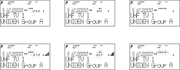
Tone SQ on,
CTCSS 123.0 Hz setting
Tone Search,
CTCSS 67.0 Hz detecting
Tone Search,
DCS 023 detecting
Tone Search,
no signal receiving
Tone SQ on,
DCS 325 setting
Tone SQ on,
CTCSS & DCS non-setting
33
Service Search
The Service Search feature allows you to toggle through the following ten preprogrammed
services. The frequencies selected for these services are the most commonly used around
the U.S.
• 1: PUBLIC SAFETY • 6: RAILROAD
• 2: NEWS • 7: AIR
• 3: TV BROADCAST • 8: CB RADIO
• 4: HAM RADIO • 9: FRS
• 5: MARINE • 0: SPECIAL (frequencies)
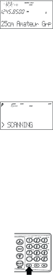
1. Press SRCH for 2 seconds. the display indicates
as illustrated.
2. After a 3 second delay, searching begins for the first
preprogrammed service – Public Safety (initial setting).
3. If you want to skip a frequency, press SRCH to start searching immediately.
4. To change the searched service, use ▲, ▼or VFO after pressing SRCH for 2 seconds.
Note: •You can not change such settings as delay, during a service search.
•The channel number corresponding to certain services will appear when a
frequency within the search is active.
•You can enter one of the Service Search frequencies into Channel Memory by
pressing Ewhen holding on one of the frequencies.
•Special Frequencies are low-power, itinerant, FRS, "splinters" and other
frequencies which are commonly used at special events and other locations and
may or may not be licensed.
5. To exit from the service search mode, press MAN or SCAN.
During the search of one of the preprogrammed services, the lower display line will indicate
the service that you are searching. To stop the search, press HOLD/▲. HOLD appears in
the display. Press HOLD/▲or LIMIT/▼to move up or down one programmed frequency, or
press SRCH to resume searching.
Service Search Skip
You can set the scanner to skip the frequencies unwanted during service search. 100
skipped frequencies are programmable.
1. To skip over a frequency, press L/O when stopping at the
frequency you want to skip.
2. To cancel a skip during search, press HOLD/▲, tune in the
desired frequency using ▲, ▼or VFO, then press L/O.
To restore all skipped frequencies, press L/O for 2 seconds.
34
Weather Channel Search
To hear preprogrammed NOAA weather channels:
1. Press WX.
Note: •It’s possible to receive more than one weather broadcast in your area. If the
broadcast sounds weak or distant, press SRCH to look for a closer station.
•Press HOLD/▲if you want to stop searching (WX hold mode).
NWR-SAME Alert
In addition to the conventional weather broadcasts, your BC780XLT is compatible with
NWR-SAME weather alert. When the scanner receives NOAA’s Specific Area Message
Encoding (SAME) coded weather emergency signal, it sounds the alert tone with specified
message. You must program your FIPS code to identify the Specific Area where you are
located.
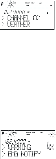
1. While receiving a weather channel or at the WX hold
mode, press WX to activate this feature. The ALT
icon displays. The audio is muted but the scanner is
still actively waiting to detect the coded SAME
emergency warning signals.
2. When the unit receives a warning signal, it shows a
message with the alert tone defined. (For NWR-
SAME Event Code, see the table in the Appendix.)
3. To deactivate, just press WX or it is automatically canceled when the channel is
changed.
Testing the Alert Siren
To test and recognize the difference between the types of alert sirens, perform the
following steps:
1. During WX hold mode, press and hold the PRI key until you hear the
Statement Alert siren. ALT appears on the display and the
Statement, watch, warning sirens sound alternately.
Note: The samples of the each alert siren only last for a few seconds. You may need to
listen to each siren several times to be sure you recognize the different sirens and
tones. The sirens continue to sound rotating through the samples until you silence
the test.
2. To stop the test, press any key.
Make sure you can hear the siren in all areas that you would need to. If not, optional
accessories can be purchased to ensure that you are alerted for emergency broadcasts.
See your dealer or local electronics store for accessories. DO NOT USE THE EARPHONE
TO LISTEN TO THE TEST. DAMAGE TO YOUR HEARING COULD OCCUR.
35
Programming FIPS Code
The 6-digit Federal Information Processing System (FIPS) codes established by the National
Weather Service (NWS) must be programmed in your scanner. These codes specify an
emergency and the specific geographic area (such as county) affected by the emergency.
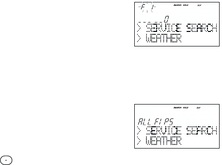
1. At the WX hold mode, press and hold WX for 2 seconds.
2. Select the desired memory number (F1-F15)
using ▲or ▼.
3. Enter FIPS code using the keypad.
4. Press E.
5. To exit from this programming mode, press WX.
––– OR –––
1. Press ▼when F1 is displayed or ▲when F15 is displayed.
2. Press E. The scanner is now set for ALL FIPS mode.
3. To cancel this ALL FIPS mode, enter individual
FIPS code again.
Note:•To cancel the entry, press .
•To obtain the FIPS code for your area, contact the NWS toll free
at 1-888-697-7263.(1-888-NWR-SAME) or visit their web site
http://www.nws.noaa.gov/nwr/indexnw.htm

36
Trunked Systems
Your BC780XLT is designed to track three major types of trunked radio systems. These
systems are described here.
❖MOTOROLA - Including Type I, Type II, Hybrid, SMARTNET, and Privacy Plus.
Motorola systems are widely used by public safety and business users. Most are on
the 800 MHz band, and recent systems are appearing on other bands. (See page 53)
❖EDACS - Including "Wideband" 9600 baud, and "Narrowband" 4800 baud systems.
"Wideband" systems are mostly on the 800 MHz band, and are used by public safety,
utilities, and business users. Some systems are used on the VHF and UHF bands.
"Narrowband" systems are used in the 935-940 MHz band, many by utilities.
(See page 49)
❖LTR - These systems are mostly for business users, and found on the UHF, 800 and 900
MHz bands. (See page 52)
For details on the operation and programming for all of these systems, see pages 36-58.
When tracking these types of systems, remember these important points:
•Your scanner defaults to monitor Motorola Type II systems; however, you can change this
if the system in your area is different. (The types of systems are discussed below.)
•The frequencies for many of the trunked public safety systems are listed in the
TrunkTracker National Public Safety Trunked System Frequency Guide included with your
BC780XLT scanner. Frequencies sometimes change, check with
www.bearcat1.com/free.htm.
•If you have internet access, you can visit scanner.uniden.com or
www.bearcat1.com/free.htm for additional information for current news and frequency
information about Trunk Tracking Scanning.
* Motorola, SMARTNET, and PRIVACY PLUS are trademarks of Motorola Inc. EDACS is a
registered trademark of the Ericsson Corporation. LTR is a registered trademark of E.F.
Johnson Company.
37
Programming and Receiving
Trunked Systems
Programming Trunking Frequencies
The first step in tracking a trunked system is storing the frequencies in one of the 10
available banks in your scanner. Remember that you can only store one trunking system in
each bank.
Important: If you are programming an EDACS or LTR trunked system, you must enter the
frequencies in a specific order. Check the frequency guide included with the
scanner for the frequencies in your area. For additional frequencies, check the
web sites listed on page 5.
1. Press MENU.
2. Press ▲or ▼to select TRUNK DATA and then
press E.
3. Press ▲or ▼to select the bank no. and then press E.
4. Press ▲or ▼to select the TRUNK TYPE and then
press E.
☞Remember! You can also use the VFO control for scrolling. Also instead of pressing
E, you can press the VFO/SELECT control or press the SELECT/MUTE key.
5. Choose the system you want to track using the
keypad, ▲or ▼and then press E.
6. To exit from this mode, press MENU repeatedly.
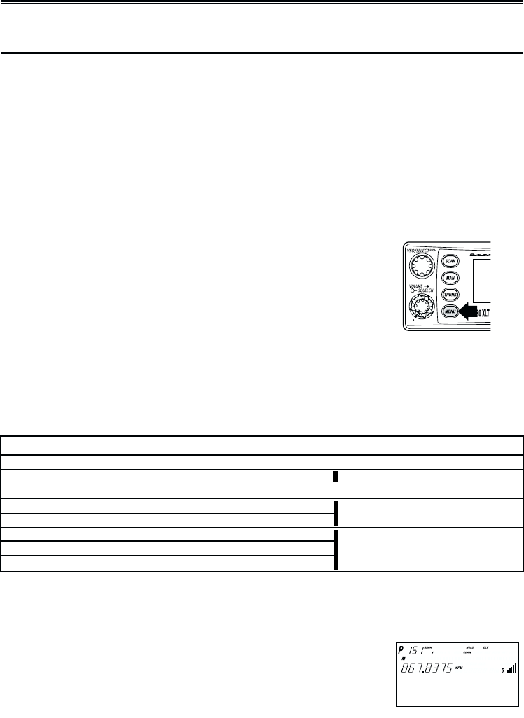
7. Select a channel using the keypad and then press MAN.
8. Enter a frequency for the trunked system using
the keypad.
For example, enter 867.8375 (Type 2) or enter a
frequency you are going to track.
No. LCD display Icon Trunking Type Special requirements
1 Type 2 800 M Motorola Type 2 800 MHz
2 Type 1 M Motorola Type 1 a. Must program a fleet map.
3 Type 2 900 M Motorola Type 2 900 MHz
4 Type 2 UHF M Motorola Type 2 UHF b. Must program base, spacing,
5 Type 2 VHF M Motorola Type 2 VHF frequency and offset channel.
6 EDCS WIDE E EDACS Wideband 9600 baud c. Must program frequencies
7 EDCS Narrow E EDACS Narrowband 4800 baud in exact order
8 LT L LTR and location.
38
☞Important!
7. Press TRUNK for 2 seconds.
A tone sounds, and E, M, or L icon appears on the display according to the system
selected.
Note:•To clear a mistake while entering the frequency,
press (decimal key) repeatedly until the
display is cleared.
•If you enter a frequency which is out of the
system’s trunking range, a distinctive beep
sounds and ERROR appears on the display.
Selecting Trunking Programming Menu Mode
To change the system type which your scanner monitors, you must be in the Trunking
Programming menu mode.
To select this mode, follow these steps:
1. Press MENU.
2. Press ▲or ▼to select TRUNK DATA and then
press E.
3. Select the bank you want to program using ▲, ▼or
VFO and then press E.
☞Remember! You can also use the VFO control for scrolling. Also instead of pressing
E, you can press the VFO/SELECT control or press the SELECT/MUTE key.
Selecting Trunking System Type
1. Select TRUNK TYPE using ▲, ▼or VFO and then
press E, SELECT or VFO.
2. Select the system type you want to program
using ▲, ▼or VFO and then press E, SELECT
or VFO.
39
Setting the Squelch
For trunked reception, a good setting for the SQUELCH control is in the center of the range
with the red marker pointing up. See the illustration.
If set too high (CCW) in some cases it could prevent your scanner from
locking to the control channel reliably. If set too low (CW) it will slightly
delay finding the control channel. The best setting is the same as for
conventional reception, and is not critical.
Receiving Trunked Systems
When you have properly programmed all the frequencies for a trunked system, you can
receive the system several different ways. You will find that Search, Hold, Lockout, Scan and
Manual are all similar to conventional scanning.
❖TRUNKED SEARCH lets you hear all system talkgroup activity (unit-to-unit I-Calls
may be received as well). This is the best way to get started.
❖ID HOLD works with Search mode to let you quickly freeze reception on an
interesting transmission. Or you can manually specify a talkgroup with DIRECT
ENTRY ID HOLD.
❖ID LOCKOUT works with Search to exclude talkgroups that you don't want to hear.
❖ID SCAN lets you receive only those talkgroups that you store in Scan Lists.
❖MANUAL lets to selectively listen to a talkgroup in your Scan Lists
When receiving EDACS systems, remember that Uniden's AFS talkgroups give you powerful
flexibility. In a few keystrokes, you can specify a single talkgroup, a fleet, or an entire agency
in all the above modes. Read the section "EDACS Reception" to understand how this works.
Trunked Search
Once you have programmed all the frequencies for a trunked system, SEARCH will let you
immediately start hearing transmissions. It is suggested you try SEARCH mode first.
1. Press SCAN, and select the bank(s) you wish to receive, just as you select banks in
conventional scanning.
2. Press TRUNK to enable trunked reception. The radio will seek and acquire the trunked
system control channel. The scanner will now be in MONITOR mode. You will hear the
control channel and see active talkgroups on the screen. You will not hear the voice
transmissions in MONITOR mode.
☞Hint: MONITOR mode is an excellent way to observe system activity and determine
which talkgroups are most active. Locked-out IDs display during MONITOR mode.
3. Press SRCH to begin searching and receiving. You will hear talkgroups and see them on
the screen.
40
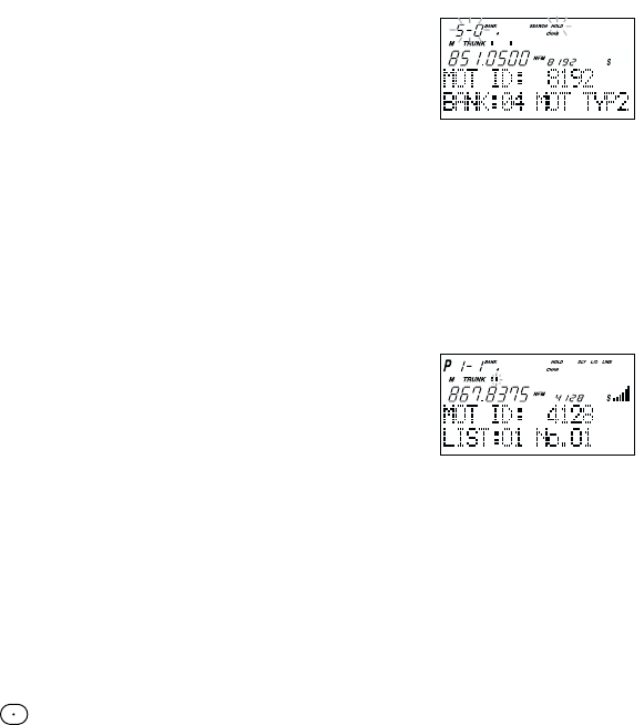
Talkgroups display differently in Motorola, EDACS and LTR systems. You should read the
appropriate parts of this guide to understand the formats.
The bottom line of the display indicates the Bank and the type of trunked system you are
monitoring. You can change this to display a bank tag by using the System Menu.
Regardless of the system, you won't know exactly who you are receiving until you listen for
a while, or refer to frequency guides or internet sites such as www.bearcat1.com. Of
course, figuring out who each ID represents is half the fun of TrunkTracking.
Later, when you learn more about a system, you will want to store lists of talkgroups.
Then you can scan specific agencies and users, and use the many other features your radio
provides.
ID Hold and Direct Entry ID Hold Mode
Just like in conventional Search, HOLD lets you pause ID Search on an interesting
transmission without storing the talkgroup into memory.
If you hear an interesting ID during SEARCH mode, and want to continue listening to it --
•Press HOLD/▲to stop the search. HOLD appears in the display.
If you want to listen to a specific ID, while in HOLD --
•Use the keypad to enter the ID you want and press
HOLD/▲. HOLD appears in the display.
If you want to stop holding --
•Press SRCH to return to Search Mode.
ID Lockout
Like conventional scanning, it’s possible to lockout unwanted traffic. This is particularly
important in trunked systems because in many areas, water meters, door alarms, traffic
signals, and other mechanical devices are assigned IDs just like other users. Also some
departments scramble or encrypt their communications, and you may want to lock out these
unintelligible broadcasts.
To lockout an ID, press L/O when the ID displays.
The ID is locked out. You can lockout up to 200 IDs.
Note: If you lockout an ID in Search mode, it is also locked out in Scan List mode.
Conversely, if you lockout an ID while in Scan List mode, it is locked out in Search
mode. For information about Scan Lists see page 42.
EDACS BLOCKOUT is a powerful form of ID LOCKOUT that can be used only with AFS
and EDACS systems. This feature lets you lock out entire Agencies or Fleets, not just
individual talkgroups. Using ID BLOCKOUT you can, for example, prevent Search from
stopping on any of hundreds of talkgroups in the Utilities agency. You can do this with just a
few keystrokes. To use ID BLOCKOUT just enter the Agency- part, or the Agency-Fleet part,
of the talkgroup code and press L/O. For example, to Blockout Agency 4 in Trunk Search,
press HOLD/▲, 04, (decimal key), and then L/O. For other ways to use partial AFS
entry, be sure to read the section "EDACS Reception".
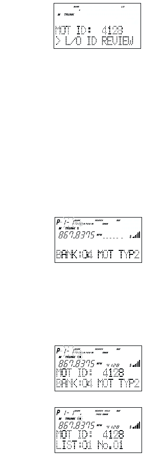
41
Restoring Locked-out IDs
To unlock a single ID, follow these steps:
1. Press MENU.
2. Select TRUNK DATA - BANK NO. - L/O ID REVIEW
using ▲, ▼or VFO and pressing E, SELECT or VFO.
3. Select the locked out ID you want to unlock using ▲or ▼.
4. Press L/O. The ID is unlocked and the next locked ID
displays.
To unlock all locked out IDs in a bank at once:
1. Press Einstead of L/O in step 4 above.
2. To exit from this mode, press MENU repeatedly.
Channel Activity Indicators
The BC780XLT has 30 Channel Activity Indicators to visually display a trunked systems
activity. You’ll always know which frequencies are in use and how much communication
traffic is occurring.
Each frequency you program in a trunking bank corresponds to an activity indicator at the
top of your scanners display. The way in which the Activity Indicators display provide you
with information about the system you’re tracking.
•The indicator which remains on, even if when there is
no traffic, represents the frequency being used as the
data channel.
•If an indicator turns on and you don't hear a
conversation, then the channel may be used as a
telephone interconnect call (some systems) or a
talkgroup that has been locked out.
•The indicator which flashes when an ID displays
represents the frequency being used by the talkgroup.
•If you're holding on an ID which isn't active, the
activity indicators will turn on and off as other groups
use the system.
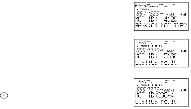
42
Scan Lists
Each bank of your BC780XLT can be a trunk tracking bank and it can be a conventional
scanning bank. When you designate a bank as a trunking bank, your scanner sets up 10
Scan Lists, which are simply lists used to store your favorite IDs. Each list can contain up to
10 IDs, so you can store a total of 100 IDs for each trunk tracking bank. (1000 if you use all
banks as trunking banks!)
Scan Lists help you organize the trunking system users into categories.
For example, you might use List#1 for police IDs, List#2 for fire department IDs, List#3 for
emergency medical service IDs, etc. Once IDs are stored in lists, you can scan them like you
scan conventional frequencies and you can lock out any one (and up to 9) of the 10 scan
lists by pressing the corresponding numeric key. When an ID is active, the scan list number
icon into which it is programmed will flash in the display (when the LIST icon is also active –
see below). You can program your scan lists either manually or during trunking search mode.
SELECT Key
Use the SELECT key while trunking to toggle between viewing the active Banks and the
active Scan Lists. To see which is currently active, check the display for either the BANK or
the LIST icon.
Check the web site www.bearcat1.com/free.htm for a complete list of talkgroups for your
area that you can program into your Scan Lists.
Programming ID Scan Lists Manually
1. Press MAN, the lowest available ID list number appears on the display.
2. Use HOLD/▲and LIMIT/▼to select the Scan List
location you want to program.
For example, select the third memory location in the
fifth scan list.
Note: You can also use the keypad to input directly.
3. Enter the Type II ID you want to store, and press E.
––– OR –––
To enter a Type I ID:
a. Enter the block number and fleet number.
b. Press .
c. Enter the sub fleet number, and press E.
––– OR –––
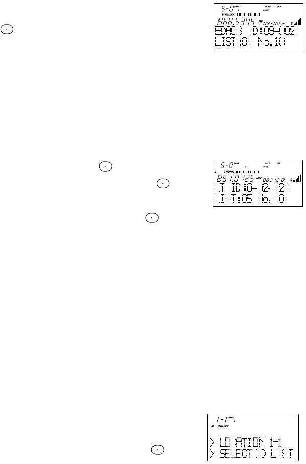
43
To enter an EDACS®ID:
a. Enter ID you want to store.
Use the for the "dash".
b. Press E.
Hint: Remember that Uniden's AFS format allows you to enter full or partial EDACS IDs for
powerful flexibility in all modes. Be sure to read the section "EDACS Reception" on
page 49 to learn how this works.
Note: The BC780XLT defaults to "AFS" talkgroup displays for EDACS®only.
––– OR –––
To enter a LTR ID:
a. Enter Area code and then press .
b. Enter Home Repeater number and then press .
c. Enter ID you want to store and then press E.
Note: To clear a mistake while entering an ID, press and Esuccessively, and
start over.
4. Press MAN or HOLD/▲to select the next Scan List location.
Programming ID Manually with the Menu Mode
Note: It is also possible to do ID programming in the menu mode by selecting TRUNK DATA
- BANK NO. - PROGRAM ID. Do the following:
1. Press MENU.
2. Press ▲or ▼to select TRUNK DATA and then press E.
3. Press ▲or ▼to select the bank no. and then press E.
4. Press ▲or ▼to select the PROGRAM ID and then press E.
☞Remember! You can also use the VFO control for scrolling. Also instead of pressing
E, you can press the VFO/SELECT control or press the SELECT/MUTE key.
5. Select the ID location using the VFO control, keypad, ▲or ▼
and then press E. (first number represents the bank number
and second number represents the memory location.)(Direct
entry method example: enter "5-1" by pressing 5, , 1.)
6. Press ▲or ▼to select ID and then press E.
7. Enter the ID number using the keypad and then press E.
Note: After you have programmed the ID in a selected bank while still in the menu mode,
you can set your alpha tag (see page 21), flag the individual ID or talkgroup for
recording (see page 32 and 11), or turn on the beep alert for an individual talkgroup
(see page 22).
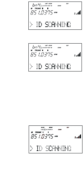
44
ID Scan Mode
1. Press SCAN to begin scanning the lists you have
programmed.
If you haven't programmed any IDs, ERROR appears
for a few seconds.
2. To remove a Scan List from active scanning, press
the number of the Scan List on your keypad.
The Scan List indicator turns off, and the IDs in that
list are not scanned.
Note: One Scan List must always be active. If you try
and deactivate all the Scan Lists, Scan List 1 will
automatically be active.
3. To restore a Scan List to active scanning, press its
number again.
4. Press SRCH to return to Trunk Tracking Search mode.
For motorola and EDACS system, to change your
display between the Scan List indicators and trunk
bank display, press SELECT.
For LTR systems only, the talkgroup must be active in
order to change the scan list and bank indicators. If
the talkgroup is not active, change the scan list by
using the menu screen.
Note:•Once you press SCAN or SRCH in one bank, all trunking banks will change to
that mode.
•Selecting a Scan List is also possible in the menu mode. (LTR only)
•ID SCANNING appears on the bottom of the screen during Trunk Scan instead
of simply SCANNING.
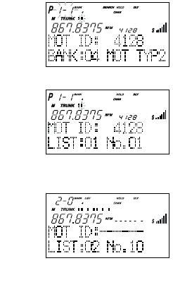
45
Setting Priority in Trunking Mode
You can set priority in your trunking lists, just as you do in your conventional ones. You can
set the priority by pressing and holding PRI for 2 seconds. After you’ve set up your Scan
List, press PRI to activate it.
It’s very similar to conventional priority although there is no "interrupt" during the
transmissions. Priorities are checked in between transmissions.
With Priority on, you can hold on an ID in your Scan List, such as Scan List 6, memory
position 7, and the scanner will check all the priorities in all the active Scan Lists every few
seconds and in between any transmissions on the ID on which you’re holding. The lowest
numbered priority will be checked first. For example, the priority ID in List 1 will be checked
before the priority in List 2, etc.
Note: This function does not work in LTR tracking.
Programming Scan Lists During Search
To select a Scan List location and store an ID during Search mode, follow these steps:
1. When your scanner stops on an ID you want to store,
press HOLD/▲.
2. Press E, or use HOLD/▲or LIMIT/▼to select the Scan
List memory location you want to change, then press E.
3. Press SRCH to return to Trunk Tracking Search mode.
Deleting a Stored ID
To delete a stored ID:
a. Press MAN.
b. Use HOLD/▲and LIMIT/▼to select the scan list
location you want to delete.
c. Press 0.
d. Then press E.
Moving between Scan List Memories
There are a number of ways to step and move through your Scan List memories:
1. Press MAN repeatedly.
2. Or, press MAN, then press HOLD/▲and LIMIT/▼.
3. Or, press MAN, next press 0- 9(scan list number), then press 0- 9(memory position),
for example. To move to Scan List 4, memory position 10, press: MAN, 4, 0, MAN

46
I-Call (Motorola/EDACS)
I-Calls are direct unit-to-unit transmissions that are not heard by other system users. Your
BC780XLT can receive these transmissions. How you receive I-Calls depends on whether
you are in Search or Scan mode.
During I-Call reception the display will show the Unit ID number of either the transmitting or
receiving mobile unit, not a talkgroup. Unit IDs will display differently according to the type of
trunked system, and will replace the 'n's shown here.
EDACS and MOTOROLA TYPE 1 innnnn
MOTOROLA TYPE 2 7nnnnnn
Hint -- There are thousands of Unit IDs in typical systems, but relatively few I-Calls at a
given moment, so it is normally best to let the scanner to receive any I-Call without
trying to specify particular units.
I-CALLS IN SEARCH MODE
In SEARCH mode, the scanner default is that I-Call reception is OFF. This means that
I-Calls will not be received until you program them to be ON. You have three choices for
controlling I-Call reception. Through the Menu system, go to TRUNK DATA / BANK NO /
I-CALL , and make your selection. The menu choices are:
In I-Call ONLY mode, the display will show I-CALL, to warn that only I-Calls will
be received.
You can HOLD any I-Call ID. Because you can only hold on one ID, and there are two IDs
involved in any I-Call communication (the transmitting and the receiving units), you might not
hear the full conversation, but you probably will.
☞In SEARCH mode, when you hear an interesting I-Call, you can enter the instant
shortcut then
SRCH to enter I-Call ONLY mode. This blocks all talkgroup traffic
and lets you hear just the I-Call. To return to normal reception, you must use the
Menu system to select the ON or OFF option.
Note: When storing I-Call IDs, remember that the ID will be for only one of the units – either
the transmitting or receiving unit. Unless you specifically want to receive a certain ID,
it might be better to use the special code in the HINT below.
I-CALLs TALKGROUPS
1 OFF Not received Received normally This is the BC780XLT default
2 ON YES Received normally Use this choice to receive I-Calls
together with normal
talkgroup traffic.
3 ONLY YES NOT RECEIVED Use this setting to listen to
I-Calls, and block all talkgroup
reception. For quick access to
this mode, press then
SRCH
.

47
I-CALLS IN SCAN AND MANUAL MODE
You can store I-Call IDs in scanlists, just like talkgroup IDs, for use by ID Scan and Manual
modes. To program a specific I-Call Unit ID into a scanlist:
EDACS or Motorola Type 1
Enter followed by the Unit ID digits, then E.
Motorola Type 2
Enter 7followed by the Unit ID digits, then E.
HINT - There is a special code to let you receive all I-Call IDs with a single scanlist entry.
Simply enter , 0, E. This will store the special code i0 in an EDACS scanlist, or
700000 in a Motorola scanlist. Then, whenever you SCAN this entry, or select it in
MANUAL, the scanner will receive any active I-Calls, regardless of the Unit IDs.
Note: Motorola I-CALL tracking performance may vary between systems.
Multi-Track
The BC780XLT allows you to track more than one system at a time. Here are some
highlights of this feature:
❖You can actually track up to 10 trunking systems at one time.
❖You can trunk scan or search and scan conventional frequencies at the same time.
❖You can program conventional frequencies in the same bank as trunking systems.
After the scanner finishes checking a trunked system for activity, it will conventionally
scan the other frequencies in the bank (remember, only trunking frequencies are
programmed in TRUNK mode).
To scan a mix of trunking and conventional banks, select the banks you wish to be active
with trunking off, then press TRUNK. The scanner will instantly begin scanning. If you have
not programmed a trunking bank with talkgroup ID’s, you will receive NO ID (----)
message for that bank. You can switch to SEARCH mode and the scanner will search for
any active ID’s on the system.
Multi-Track Operational Details
When more than one trunk system is active (for example two or more trunked systems or a
trunked system and one or more conventional frequencies), the radio jumps between
systems/frequencies as follows:
TRUNK SCAN: The scanner moves to a trunked system and looks for IDs in your Scan
List(s) for up to one second. If it finds no activity on your programmed talkgroups, it
moves on to conventional channels in the same bank or to the next active bank.
If the scanner finds that a talkgroup in one of your active Scan Lists is on the air, you will
begin to hear that communication and the scanner will of course display the proper
talkgroup number and any alpha tag. When the communication ends, the scanner will wait
for any delay period (such as a default of two seconds) for any further replies and, if none,
the scanner will move to the conventional channels in the same bank or to the next bank.
The scanner will not look for any other IDs within the same trunked system (as this
would slow the scan process). Note that if you press SCAN while you are listening to
one ID, the scanner will check to see if another ID in your Scan List is active. It will
disregard the ID to which you were just monitoring.
48
TRUNK SEARCH: This mode works similarly to TRUNK SCAN. If the scanner finds any
(non-locked-out) ID when it checks the control channel, you will hear it. You will then hear
any replies that follow within two seconds (or whatever delay you may have set). After that
the scanner will move on and not continuously search the system for additional IDs (on
busy systems you would never leave the system if this were the case). Note that if you
press the SRCH key while monitoring one ID, the radio will check if any other IDs are
active (it will disregard the ID you just left), and if none are active, it will move on.
LIMIT/▼KEY: If you wish to exit a trunked system without waiting for the currently active
talkgroup to finish its communication, press the LIMIT/▼key. This is particularly helpful on
very busy systems where many talkgroups are active and activity is frequent and long-
lasting. Pressing this key will move the scanner on to the conventional frequencies in the
same bank or the next bank.
SCAN & SEARCH Icons
For the first time on a Uniden scanner, you will see both the SCAN and the SEARCH
icons active at the same time. This indicates that the radio is scanning conventional banks
and Trunk searching trunking banks. When the radio is trunking, only the SEARCH icon
will be lit. Note that to start a conventional search, you must place the radio into
conventional manual mode and then press the SEARCH key.
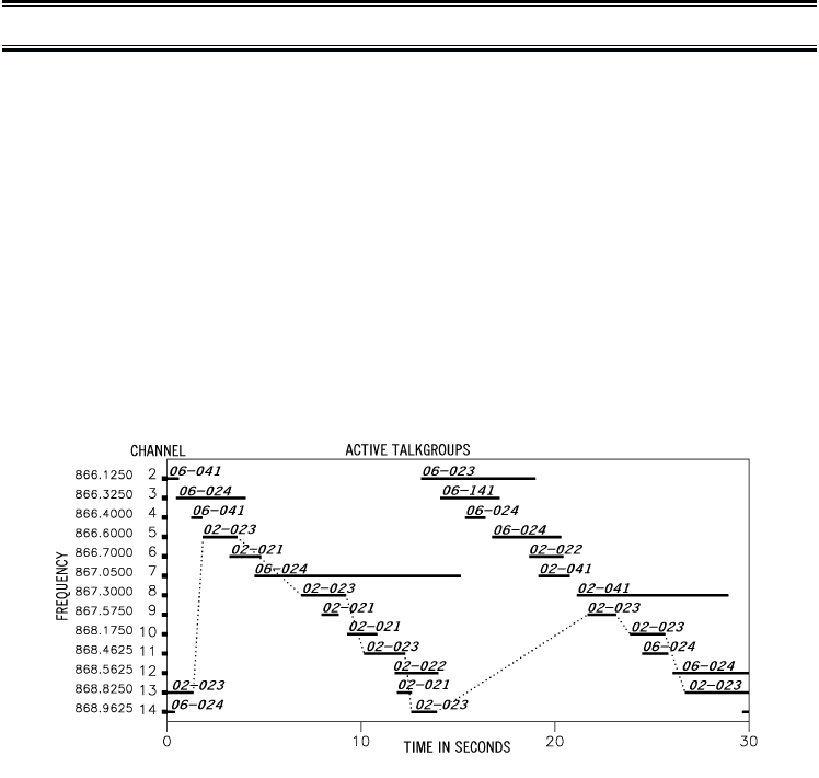
49
EDACS®Reception
EDACS®Tracking
TrunkTracker III now allows tracking of EDACS®trunked systems. Until now these widely
used systems have been almost impossible to monitor with a conventional scanner. With
your TrunkTracker III listening to EDACS(s) is remarkably easy, and perhaps even easier
than conventional scanning.
EDACS systems use 'Transmission Trunking', which means that each transmission is
assigned a new frequency. As the conversation moves through the system's frequencies,
your TrunkTracker II automatically follows it.
This chart shows a 30 second sample of EDACS transmissions. Eight different talkgroups
are using the system as their transmissions switch between the thirteen system frequencies.
Notice how the dotted line shows talkgroup 02-023 moving from channel to channel. Your
BC780XLT can clearly and automatically follow this talkgroup, or any other, as you select.
EDACS systems are organized in a logical way that keeps related talkgroups together. Your
scanner is designed to take maximum advantage of this organization to make your scanning
easy. It lets you zero in on just the part of the system you want to hear, whether it is an
individual channel or an entire department or city.
Programming EDACS System Frequencies
When you program EDACS frequencies, it is critical that you store each one in the
CORRECT LOCATION. By the nature of EDACS systems this is necessary for tracking. This
often is not the frequency order, so you must be sure you have the right sequence. Sources
for this information can be found at scanner.uniden.com.
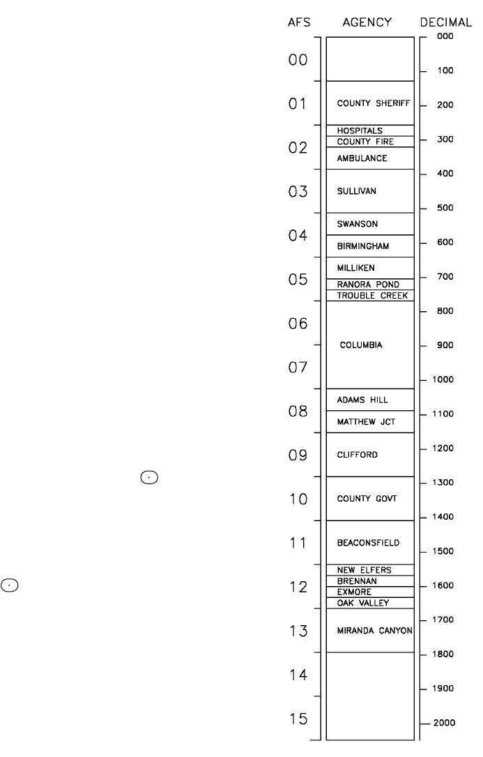
50
An EDACS®Trunked system
This chart shows how talkgroups are organized
within an EDACS system at the AGENCY level.
The individual talkgroups cannot be shown at this
scale because there are over 2000. However the
chart can show the 16 Agencies in this example.
The system is logical and easy to understand.
EDACS systems are typically arranged in an
outline structure.
The system users are given blocks of talkgroups.
Sizes vary but most large cities and other agencies
have blocks of 128 channels. Smaller cities have
only 64 or 32 channels.
In this example, the County Sheriff is agency 01.
The city of Sullivan is Agency 03. Adams Hill and
Matthew Junction share Agency 08.
Your scanner shows EDACS talkgroups in AFS
(Agency-Fleet-Subfleet) format. This helps you see,
at a glance, who you are monitoring. And with the
partial-entry feature you can easily include nearby,
related channels in the same Fleet or Agency. You
can just as easily exclude entire unwanted Fleets
and Agencies.
When in Search mode, with the system frequencies
programmed, and your scanner locked to the control
channel, you can select a desired city by keying in
the AGENCY part of the AFS talkgroup. For
example, you can select the entire city of Sullivan
with 4 key presses zero, three, , SRCH.
When you hear an interesting talkgroup, capture it to
your scan list by pressing Eduring the transmission.
Or HOLD on it by pressing the HOLD key.
If you want to monitor the Sullivan Police Dispatch
channel (which is talk group 03-062), press zero,
three, , zero, six, two, HOLD.
Your scanner can also work in DECIMAL format.
This talkgroup in decimal format is 434. But decimal
format does not give you any information about the
system hierarchy. For example Sullivan, in decimal,
uses channels from 384 to 511. This is not as easy
to remember as Agency 03. But decimal is useful if
you need to work from decimal talkgroup lists.
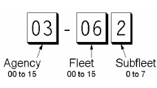
51
Special EDACS®Features
AFS Partial Entry Feature
AFS is Uniden's method of encoding EDACS talkgroups. AFS stands for 'Agency-Fleet-Subfleet'.
AFS talkgroups are used in all EDACS reception -- in ID SEARCH, ID LOCKOUT and ID SCAN
scanlists. The powerful AFS Partial Entry feature designed into the BC780XLT lets you use
either a complete talkgroup code, or just the most significant part.
This feature lets you expand or narrow searching and
scanning to one of 4 levels. By entering only the desired
part of an AFS talkgroup, you can select 2048 talkgroups,
128 talkgroups, 8 talkgroups, or a single talkgroup. For
example, you could program every talkgroup in a police
department with just 4 key presses. You can use the AFS
Partial Entry feature anywhere that you need to specify EDACS talkgroup.
Your BC780XLT can also enter or display EDACS talkgroups in decimal format (0-2047).
Press MENU - TRUNK DATA, and for banks selected as EDACS banks, select Item 8,
EDACS ID FORM and change it to Decimal. You can use this feature to translate decimal
talkgroups lists to the much more powerful AFS format.
Examples of how you might use AFS are shown above in the description of an EDACS
trunked system, and elsewhere in this manual. It is very easy to use. Be sure to become
familiar with AFS Partial Entry, and your scanning will become far more flexible and efficient.
Emergency Call Alert
Your BC780XLT alerts you when an EDACS Emergency transmission occurs.
EDACS systems often provide users with an 'Emergency' button on their radios. Users in
trouble can alert the dispatcher and other units and get priority access to the radio system.
When a user activates Emergency mode your scanner will flash EMERGENCY during the
entire transmission. At the beginning of each transmission it will sound a distinctive
emergency alert tone three times.
Patch Tracking
The BC780XLT can follow EDACS patched talkgroups.
EDACS systems sometimes bring several talkgroups together in a 'Patch'. A patch might be
used by a police agency at night to provide a single channel with a single dispatcher for a
wide area. A patch is created when a single, temporary talkgroup substitutes for the original
talkgroups. While the patch is running, which may be for hours or days, the original
talkgroups cease to be used. If you were monitoring one of these talkgroups, you might think
there was no traffic, but in fact the talkgroup was operating at the different temporary number.
If a talkgroup in your Scan List is patched, your scanner will continue to receive it under its
new identity until the patch is ended. When a patch is being received, the radio will display
[PATCH ID], and will show the temporary common talkgroup plus all the included talkgroups
in a cycling display. The BC780XLT is limited to following one patch.
The temporary talkgroups used for patches are usually found in AFS code 15-xxx, and
sometimes 00-xxx.

52
LTR®Reception
LTR®Tracking
LTR®(Logic Trunked Radio) systems are trunking systems used primarily by business or
private communications service providers, such as taxicabs, delivery trucks, and repair
services. These systems encode all trunking information as digital subaudible data that
accompanies each transmission. Users on an LTR system are assigned to specific
talkgroups, which are identified by the radio as six digit numbers. These numbers are in the
form AHHUUU, where:
A= Area code (0 or 1)
H= Home repeater (01 through 20)
U= User ID (000 through 254)
When the scanner receives a transmission on a channel set to the LTR mode, it first
decodes the LTR data included with the transmission. In the ID Search mode, the scanner
stops on the transmission and displays the talkgroup ID on the display. In the ID Scan mode,
the scanner only stops on the transmission if the LTR data matches a talkgroup ID that you
have stored in the bank’s talkgroup ID list and have not locked out.
LTR systems are frequently programmed so that each radio has a unique ID code.

53
Motorola Tracking
There are really two types of Motorola trunking systems. These are usually referred to as
Type I and Type II systems. Type I only occurs on some 800 MHz systems. All VHF, UHF
and 900 MHz trunking systems use Type II.
One important distinction between these two systems is the amount of data transmitted by
each radio when its push-to-talk button (PTT) is pressed. Every radio in a trunked system is
assigned a unique ID so the central site computer can identify it when it’s used. Both Type I
and Type II systems place radios (or radio users) into groups, called talkgroups, and these
talkgroups are also assigned unique IDs. Some radios have access to only one talkgroup,
while others have access to many talkgroups. The talkgroup(s) each radio can access is
called the radio’s affiliation(s).
In a Type II system, when someone uses their radio, only the radio ID is transmitted when
PTT is pressed, whereas in a Type I system the radio ID and its current affiliation are both
transmitted when PTT is pressed.
Why the difference? Type II systems are slightly more advanced because the central
computer maintains a database which is used to determine each radio’s affiliation (s).
Changes to a Type II system are easier than Type I because the system manager only
needs to update the database instead of reprogramming individual radios.
Another difference between the systems is that Type I systems are arranged in a Fleet-
Subfleet hierarchy. For example, its possible for a city using a Type I system to designate 4
Fleets, each with 8 Subfleets. Their fleets might be the Police Department, the Fire
Department, Utilities, and Administration. The Police may decide to further divide their fleet
into subfleets such as Dispatch, Tactical Operations, Detectives, North, South, East and
West Side Patrols, and Supervisors. All the available police radios would then be assigned
to one of the police subfleets. Determining the exact Fleet-Subfleet hierarchy for a particular
area is referred to as Fleet Map Programming, which is discussed further in this manual.
The disadvantage of a Type I system is that when PTT is pressed, the brief burst of data
must contain the radio’s ID and its Fleet and Subfleet. This is three times the amount of data
a Type II system radio sends, and as a result Type I systems usually accommodate fewer
users than Type II systems.
Even though there are many Type II systems, Type I systems are still in use. There are also
Hybrid systems which are a combination of both Type I and Type II. Your scanner defaults to
monitor Type II systems, but its possible to select a Preprogrammed Fleet Map or create a
Custom Fleet Map for your area.
For VHF and UHF Type II trunking systems, you will need to know the base, spacing
frequencies and offset channels. See page 55 for details.
Motorola Reception
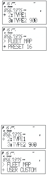
54
Fleet Map Programming
If you have programmed a trunk tracking bank for Motorola type and press TRUNK to start
Multi-Track, you will see user IDs display on your screen. Since the BC780XLT defaults to
Type II systems, all the IDs will appear as numbers. However, if you notice a mix of odd and
even user IDs, for example 6477, 2560, 6481, 6144, 1167, etc., then you are probably
monitoring either a Type I or Hybrid systems.
You may also notice that you are missing responses when you hold on an active ID. Unlike
Type II, Type I/Hybrid systems require a Fleet Map that sets specific Fleet-Subfleet
parameters. It is easy to select a Fleet Map for your scanner; what is not always easy is
selecting or programming a map that matches your particular area.
There are 16 preset Fleet Maps listed in the appendix that you can choose, and these are
usually a good place to start when setting up a Type I/Hybrid trunk tracking bank. If you
choose a preset map and still have difficulty following complete conversations, then you'll
have to program your own Fleet Map.
Selecting Preset Fleet Map
1. Select TYPE 1 for the Trunk Type. (Refer to "Selecting Trunking
System Type" on page 38.)
2. Select the map you want to program using ▲, ▼
or VFO and then press E, SELECT or VFO.
For example, PRESET 16.
The scanner returns to the other programming items.
Note: You will now begin to see Type I Fleet-Subfleet IDs. For example, 100-12, 100-9,
000-12, 400-8, etc. See User Defined Fleet Maps in the Appendix for more
information about Type I IDs.
How do you know if the preset map is correct? You will have to listen to see if you're
following complete conversations. If not, you should try another preset map.
Programming a Fleet Map
You may want to read User Defined Fleet Maps in the Appendix before programming a Fleet
Map. It contains a detailed explanation of Scanner Fleet Map Programming, as well as a
table listing the Fleet Map Size Codes.
1. Select TYPE 1 for the Trunk Type. (Refer to "Selecting
Trunking System Type" on page 38.)
2. Select USER CUSTOM using ▲, ▼or VFO and then
press E, SELECT or VFO.
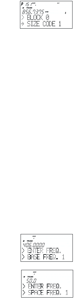
55
3. Select the size code for the first block using
▲, ▼, or VFO.
4. Press E, SELECT, or VFO.
The next available block displays.
5. Repeat step 3 and 4 until you have selected a size
code for each block.
For details about each size code, see Fleet Map Size
Codes in the Appendix.
Programming a Hybrid System
A Hybrid system is simply a Type I system with some blocks designated as Type II blocks.
To program a Hybrid system, follow the steps listed in Programming a Fleet Map in the
previous section. However, if you want a block to be Type II, select Size Code S-0.
When you begin searching a trunking bank with a Hybrid Fleet Map, you will see both types
of system IDs. That is, Type II IDs usually appear as an even number without a dash; Type I
IDs appear as a three or four digit number, followed by a hyphen, followed by a one or two
digit number.
Setting the Base, Spacing Frequencies and Offset Channel for Motorola
VHF/UHF Trunked Systems
To properly track Motorola VHF and UHF trunked systems you must enter what is known as
the base, the spacing frequencies and offset channels for each system.
To find these out, check the www.trunktracker.com or www.bearcat1.com/free.htm and
other web sites and frequency resources.
To enter the base, spacing frequencies and offset channel: (You can set up to three sets of
these, but almost all systems only use one set)
1. Press MENU.
2. Select TRUNK DATA - BANK NO. - TRUNK TYPE (TYPE2 UHF or VHF) – BASE
CONFIG using ▲, ▼or VFO and pressing E, SELECT or VFO.
3. Enter a new base frequency with the keypad.
4. Press E.
The display changes for entering the spacing frequency.
5. Enter a new spacing frequency with the keypad.
Note: You can only enter within a range of 5-100 kHz, and 5
or 7.5 or 12.5 kHz multiples.
6. Press E.
The display changes for entering the offset channel.

56
7. Enter a new offset channel with the keypad.
Note: You can only input within a range of 380-759.
8. Press E.
The display changes for entering the next base frequency.
9. To exit from this mode, press MENU repeatedly.
Note: •If the system is not tracking properly, you may need to try a new base frequency or
offset channel or you may be missing frequencies from the system.
•You can set up to three base, spacing and offsets for Motorola VHF/UHF trunked
systems.
10. The offset channel for the first set should be CH380 (just press Eto confirm this as the
default).
11. After you have pressed Eto confirm CH380, the display will change to allow you to set
the second (of a maximum of three) base/space/offset combinations. Since almost all
systems only use one set, press MENU to exit the programming mode and return to
scanning.
Toggling the Status Bit
On Type II trunking systems there is a method by which specialized types of
communications utilize unique talkgroup numbers. An emergency call will occur on a unique
talkgroup from its primary assignment, for example. Because the BC780XLT defaults to
Status-Bit On mode, you never need to worry about missing these transmissions. If you
have programmed talkgroup 33264 into Scan List memory, for example, and there is an
emergency call within the group, you will hear it on 33264.
The only time you may wish to turn Status Bits off is if you're trying to figure out the proper
fleet map of a Type 1 trunking system. To turn Status Bits off, enter into the menu mode and
select TRUNK DATA - BANK NO. - STATUS BIT. (This feature does not apply to EDACS
and LTR operation within the scanner.) Then use HOLD/▲or LIMIT/▼to change the setting
(on to off) and press Eto program your change.
57
Control Channel Only Mode
When this function is activated, trunking is performed using control channel data only. Voice
channel (also known as "working channel") frequencies do not have to be programmed into
memory. When using this feature, the scanner will display "CC" and channel activity indicator
bars will not operate. This feature only applies to Motorola 800 MHz and 900 MHz systems.
To turn this function on, choose Motorola Type-2 800 MHz or 900 MHz or TYPE 1 by
selecting TRUNK DATA - BANK NO. - TRUNK TYPE. Then set to the desired control plan
selecting TRUNK DATA - BANK NO. - CTRL CH ONLY.
You must choose one of 4 frequency plans before you begin to Control Channel Trunk. Note
that the default, Plan 1, is the most common. Read the description of the Plans below for
details on which may apply for you.
PLAN 1: Use Plan 1 if the last three digits of ALL the frequencies in use end in one of the
following three digits: 125, 375, 625, or 875 (example: 856.1125, 860.7375, 859.6625,
855.8875).
PLAN 2: If the last three digits of frequencies less than 869.0000 end in one of the
following three digits (125, 375, 625, or 875) AND if ANY other frequencies end in (000,
250, 500, or 750) use Plan 2.
PLAN 3: If the last three digits of ALL the frequencies in use end in one of the following
three digits (000, 250, 500, or 750) use Plan 3.
PLAN 4: If the last three digits of frequencies less than 866.0000 end in one of the
following three digits (000, 250, 500, or 750) AND if ANY other frequencies end in (125,
375, 625, or 875) use Plan 4.
Of course you will know the Control Channel frequency itself so that will help you determine
the proper Plan. If you try one plan and you receive errors (such as the scanner jumping to
channels that are obviously not part of the system), you should try an alternate Plan.
Note: You can assign a fleet map to Type 1 or Hybrid systems scanned in Control
Channel only mode by going into the menu. You can also program IDs, set delays,
alpha tags and all the other parameters for systems scanned in this mode. You can
then either search the system to find new IDs or you can program IDs into memory
and then scan them.
Note: The Control Channel Only feature is an extremely powerful tool. You can use it to
determine if systems you are familiar with may have added new frequencies or you
can use it to discover new systems by simply finding active control channels (using
Search) and then programming them for Control Channel operation only.
Remember that this feature only applies to Motorola 800 and 900 MHz systems,
that you do have to set the menu for the proper system type (800 Type 1 or Type II
or 900 MHz) and you do have to program the control channel frequency into
memory and press and hold the TRUNK key to identify the frequency as trunked.
58
Disconnect Tone Detect Option (End Code)
When this function is disabled, the radio looks for squelch before returning to the control
channel instead of waiting for the disconnect tone. Only in rare instances will you need to
adjust the default settings.
The condition to return to control channels depends on whether the signal is present or not.
To set this function on/off, enter TRUNK DATA - BANK NO. - END CODE.
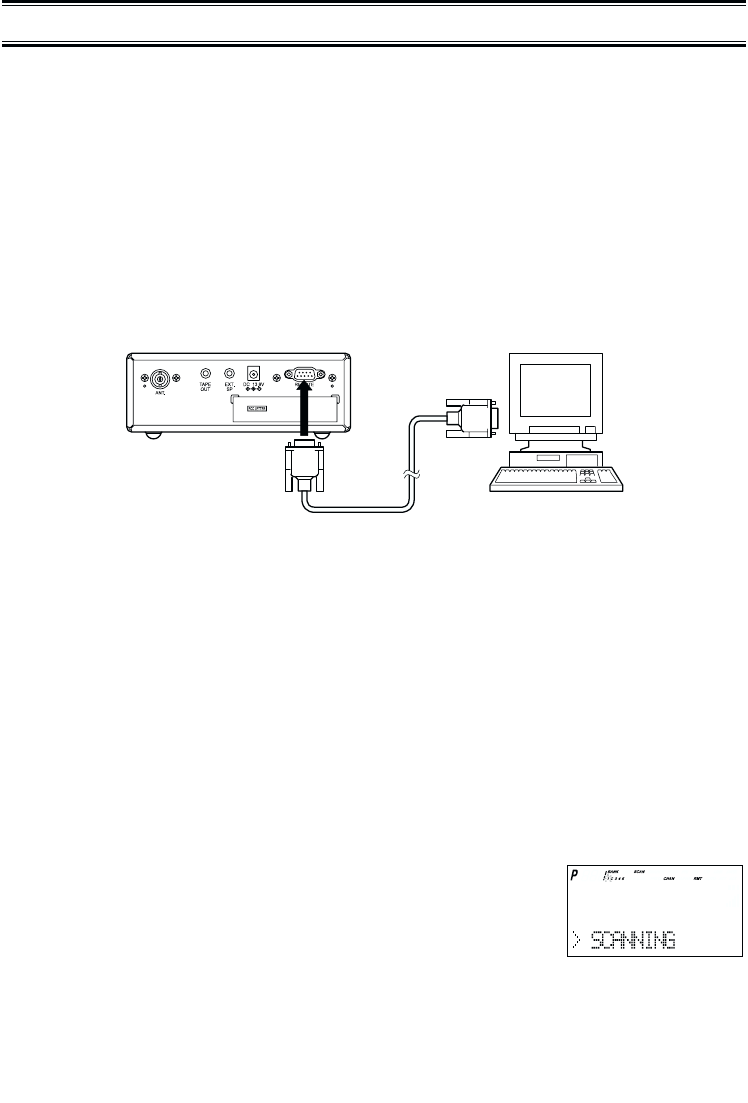
59
You can communicate and program your BC780XLT in numerous ways with peripheral
devices using the Remote Interface Cable port. This radio offers the following modes:
❖PC Control MODE
Program and control your scanner from a PC using third party software.
❖CLONE MODE
Clone all the frequencies, trunking talkgroups, and fleet maps programmed into your
scanner to another BC780XLT scanner.
Remote Interface
PC Control Mode
To connect Scanner to PC:
Plug the scanner end of the RS232C straight interface cable into the remote port on the rear
of your scanner.
Plug the other end of the cable (DB-9 serial connector) into a personal computers serial port.
A few PCs may require an adapter, most will not. You may need a DB-9 to DB-25 null
modem adapter, or gender changer adapter, available at most computer stores. Of course,
make sure your PC is turned on.
To program your scanner:
You can program and control your scanner remotely from a PC using third party software.
After connecting the scanner to a PC, turn the radio on.
To use the Remote (PC Control) mode, you must purchase third party software and use as
directed. Make sure that your scanner is connected to the serial port of the PC using the
RS232C straight cable.
Start Remote Mode:
Press Ekey for 2 seconds. REMOTE mode is selected.
To distinguish from Normal operation mode, " RMT" icon
appears.
A unique feature of the BC780XLT is that all the front panel keys as well as the VFO on the
radio remain operational in remote mode.
For information on purchasing cables, connectors, and third party software to program and
control your BC780XLT, you can contact the following:
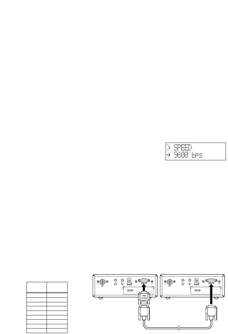
60
Uniden Parts Department (800) 554-3988
(Hours are from 7:00 a.m. to 5:00 p.m. Central Time Monday through Friday)
scanner.uniden.com
Scanner Master (800) 722-6701
(Hours are from 10:00 a.m. to 5:00 p.m. Eastern Time Monday through Friday)
PC Control Parameter
For your information:
Transfer speed : 2400/4800/9600/19200 bps (adjustable)
Start/Stop : 1 bit, 1 bit
Data Length : 8 bit
Parity bit : None
Code : ASCII code
Flow Control : None
Return Code : Carriage Return only
Change Transfer Speed
To change transfer speed, enter into the menu mode.
1. Press MENU.
2. Press ▲or ▼to select SYSTEM DATA and then press E.
3. Press ▲or ▼to select PC CONTROL and then press E.
4. To change the transfer speed, press ▲or ▼. Then press E.
Clone Mode
You will need to purchase an RS232C cable and a null modem adapter. RS232C cables are
available as male to male or male to female. Even if the cable you buy already has the Male
to Male connectors, you will still have to have the null modem adapter. Below you will see
the pin connections that are internal to a standard device. (These items are available at your
local electronics stores.)
To connect the scanner to scanner:
Plug the male end of the RS232C straight interface cables into the remote port on the rear
of one of the two scanners. Then connect the DB-9 to DB-9 null modem adapter to the
cable. Then plug the other side of the null modem adapter to the other scanner.
(DB9 Gender changers are also available at your local electronics store.)
Female
DB9
Male
DB9
14
23
32
46 & 1
55
64
78
87
9Not used
Null Modem Adapter
Pin connections
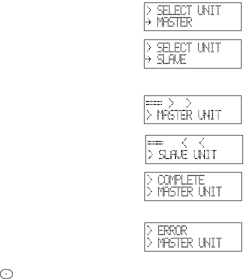
61
You can clone all of the programming of one BC780XLT into another, including frequencies,
talkgroup IDs, alpha tags, delay settings, etc. After connecting the two scanners, turn the
radios on. Prepare each scanner for clone mode as follows.
1. Press MENU.
2. Select SYSTEM DATA - CLONE using ▲, ▼or VFO and pressing E, SELECT or VFO.
3. Determine the scanner that has the frequency data that you want to transfer. This one
must be set up as the "Master Unit", and the other must be set as the "Slave Unit".
4. On the scanner that is the "Master Unit",
select MASTER, then press E.
5. On the scanner that is the "Slave Unit",
select SLAVE, then press E.
6. Press the SCAN key on both scanners. The data transfer is
started from the Master Unit to the Slave Unit.
During the data transfer, both scanners show
the following displays.
When the data transfer is completed,
COMPLETE displays.
If the data transfer is not successful, the
following error message will appear.
Note: To clear ERROR, press .
To exit the clone mode, press the menu key repeatedly.
Note: Once you have completed the cloning of the scanners, reset by turning the scanners
off and then on again. This is particularly important to know if you wish to clone
another scanner right away.

64
General Use
•Turn the scanner off before disconnecting the power.
•Always write down the programmed frequencies in the event of memory loss.
•If memory is lost, simply reprogram each channel. The display shows 000.0000 in all
channels when there has been a memory loss.
•Always press each button firmly until you hear the entry tone for that key entry, unless you
have turned off the KEY BEEP in the menu system.
Location
•Do not use the scanner in high-moisture environments such as the kitchen or bathroom.
•Avoid placing the unit in direct sunlight or near heating elements or vents.
•If the scanner receives strong interference or electrical noise, move it or its antenna away
from the source of the noise. If possible, a higher elevation, may provide better reception.
Also try changing the height or angle of the antenna.
Cleaning
•Disconnect the power to the unit before cleaning.
•Clean the outside of the scanner with a mild detergent. To prevent scratches, do not use
abrasive cleaners or solvents. Be careful not to rub the LCD window.
•Do not use excessive amounts of water.
Repairs
•Do not attempt any repair. The scanner contains no user serviceable parts. Contact the
Uniden Customer Service Center or take it to a qualified repair technician.
Birdies
•All radios can receive birdies (undesired signals). If your scanner stops during Scan mode
and no sound is heard, it may be receiving a birdie. Birdies are internally generated
signals inherent in the electronics of the receiver.
Press L/O to lockout the channel, and then press SCAN to resume scanning.
Care and Maintenance

Important: Evidence of original purchase is required for warranty service.
WARRANTOR: UNIDEN AMERICA CORPORATION (Uniden)
ELEMENTS OF WARRANTY: Uniden warrants, for one year, to the original retail owner, this
Uniden product to be free from defects in materials and craftsmanship with only the
limitations or exclusions set out below.
WARRANTY DURATION: This warranty to the original user shall terminate and be of no
further effect 12 months after the date of original retail sale. The warranty is invalid if the
Product is (A) damaged or not maintained as reasonable or necessary, (B) modified, altered,
or used as part of any conversion kits, subassemblies, or any configurations not sold by
Uniden, (C) improperly installed, (D) serviced or repaired by someone other than an
authorized Uniden service center for a defect or malfunction covered by this warranty,
(E) used in any conjunction with equipment or parts or as part of any system not
manufactured by Uniden, or (F) installed or programmed by anyone other than as detailed
by the owners manual for this product.
STATEMENT OF REMEDY: In the event that the product does not conform to this warranty
at any time while this warranty is in effect, warrantor will either, at its option, repair or replace
the defective unit and return it to you without charge for parts, service, or any other cost
(except shipping and handling) incurred by warrantor or its representatives in connection
with the performance of this warranty. Warrantor, at its option, may replace the unit with a
new or refurbished unit. THE LIMITED WARRANTY SET FORTH ABOVE IS THE SOLE
AND ENTIRE WARRANTY PERTAINING TO THE PRODUCT AND IS IN LIEU OF AND
EXCLUDES ALL OTHER WARRANTIES OF ANY NATURE WHATSOEVER, WHETHER
EXPRESS, IMPLIED OR ARISING BY OPERATION OF LAW INCLUDING, BUT NOT
LIMITED TO ANY IMPLIED WARRANTIES OF MERCHANTABILITY OR FITNESS FOR A
PARTICULAR PURPOSE. THIS WARRANTY DOES NOT COVER OR PROVIDE FOR THE
REIMBURSEMENT OR PAYMENT OF INCIDENTAL OR CONSEQUENTIAL DAMAGES.
Some states do not allow this exclusion or limitation of incidental or consequential damages
so the above limitation or exclusion may not apply to you.
LEGAL REMEDIES: This warranty gives you specific legal rights, and you may also have
other rights which vary from state to state. This warranty is void outside the United States of
America.
PROCEDURE FOR OBTAINING PERFORMANCE OF WARRANTY: If, after following the
instructions in the owners manual you are certain that the product is defective, pack the
Product carefully (preferably in its original packaging). The product should include all parts
and accessories originally packaged with the Product. Include evidence of original purchase
and a note describing the defect that has caused you to return it. The Product should be
shipped freight prepaid, by traceable means, to warrantor at:
UNIDEN AMERICA CORPORATION
Parts and Service Division
4700 Amon Carter Boulevard
Fort Worth, TX 76155
(800) 554-3988, 7 a.m. to 5 p.m. Central Time, Monday through Friday
One Year Limited Warranty