Uniden America UB331 MOBLE TYPE SCANNER User Manual Precautions
Uniden America Corporation MOBLE TYPE SCANNER Precautions
UserManual.wiki
>
Uniden America
>
UB331 User Manual
USERS MANUAL
Navigation menu
Upload a User Manual
Namespaces
Wiki Guide
HTML
PDF
Info
Views
User Manual
Discussion / Help
Navigation
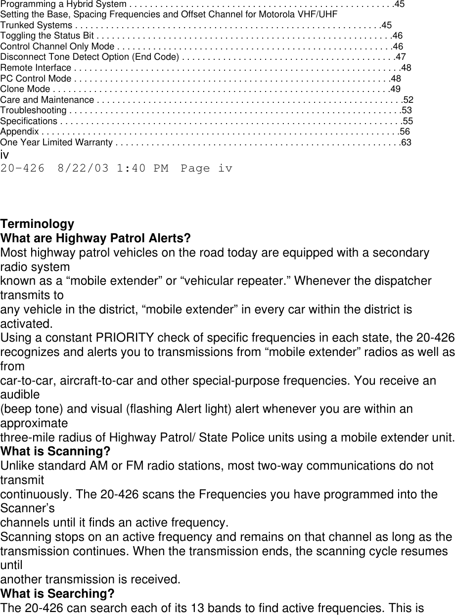
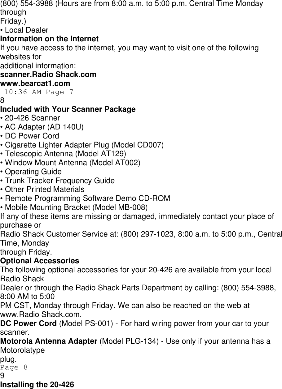
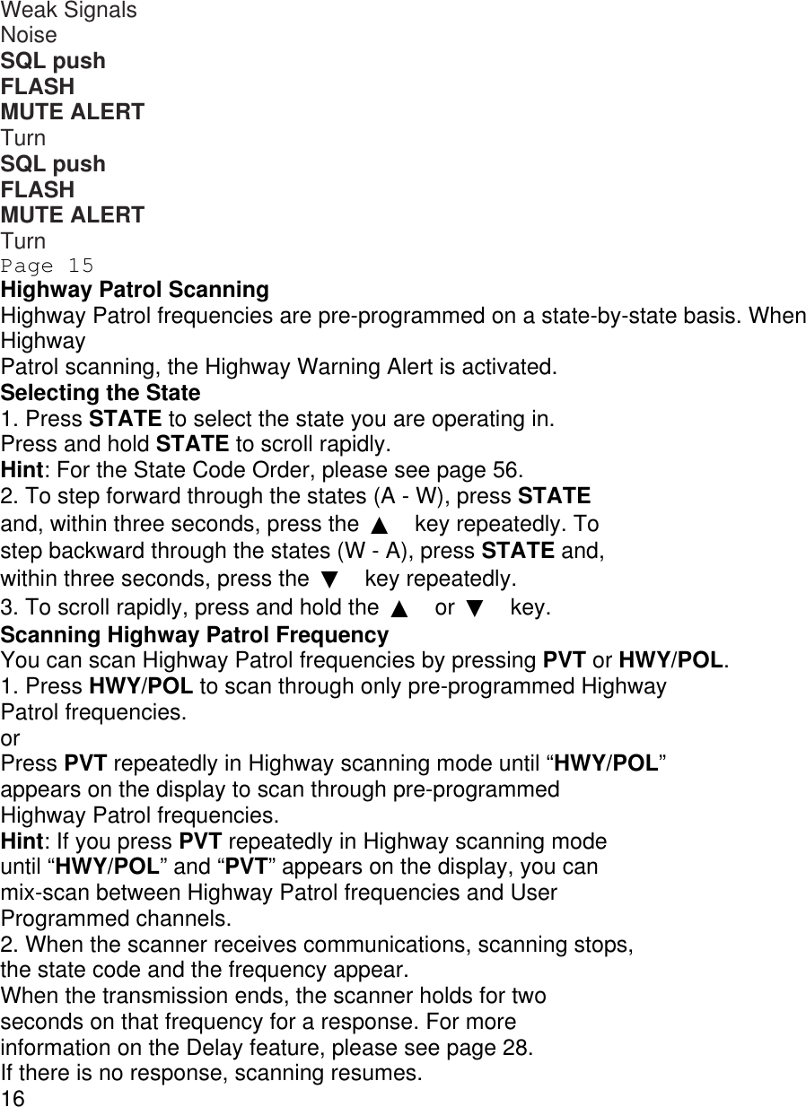
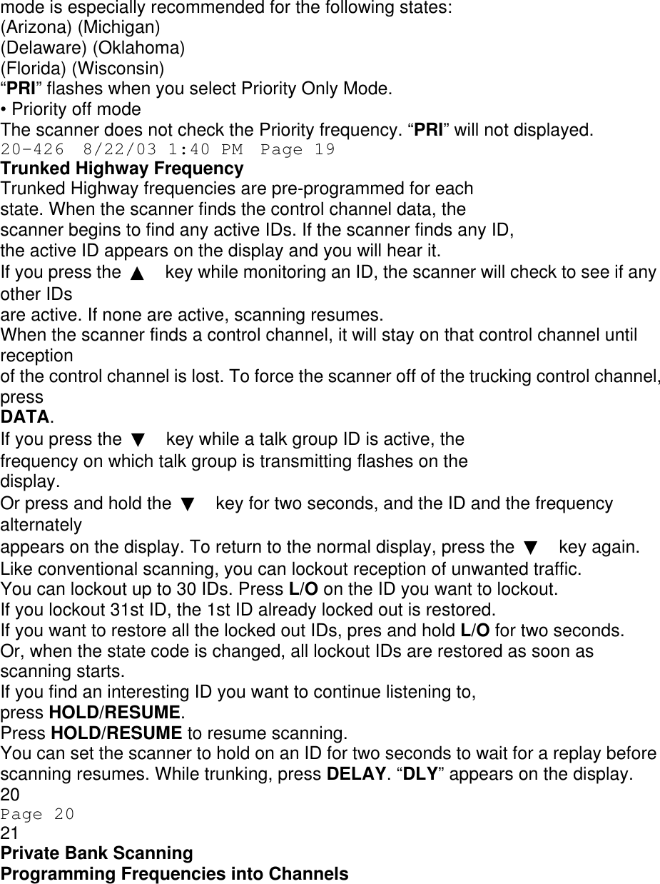
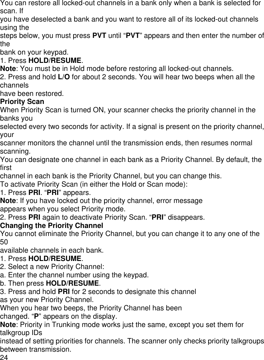
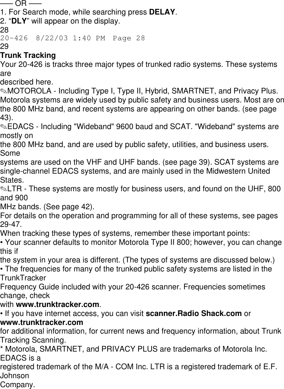
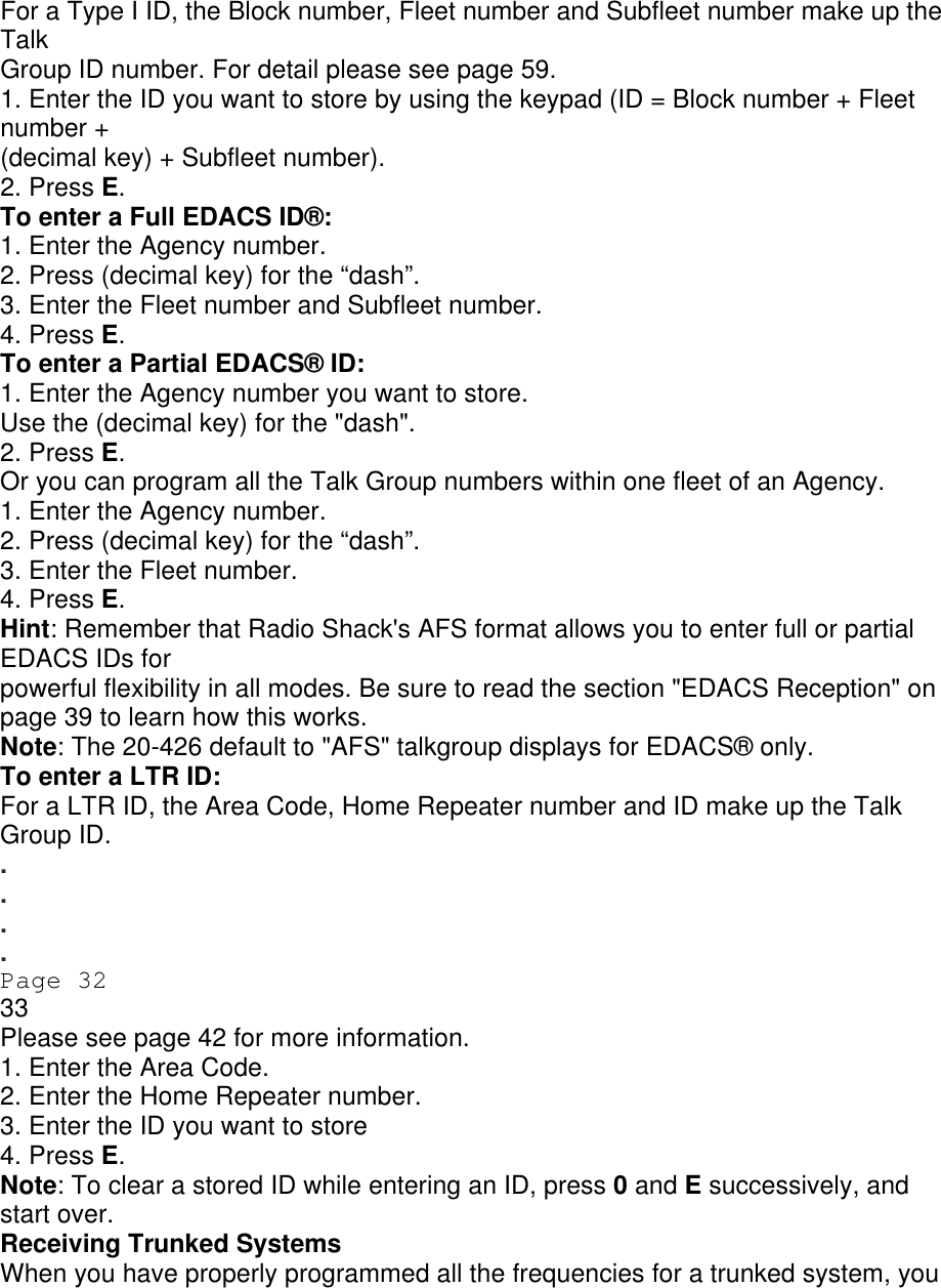
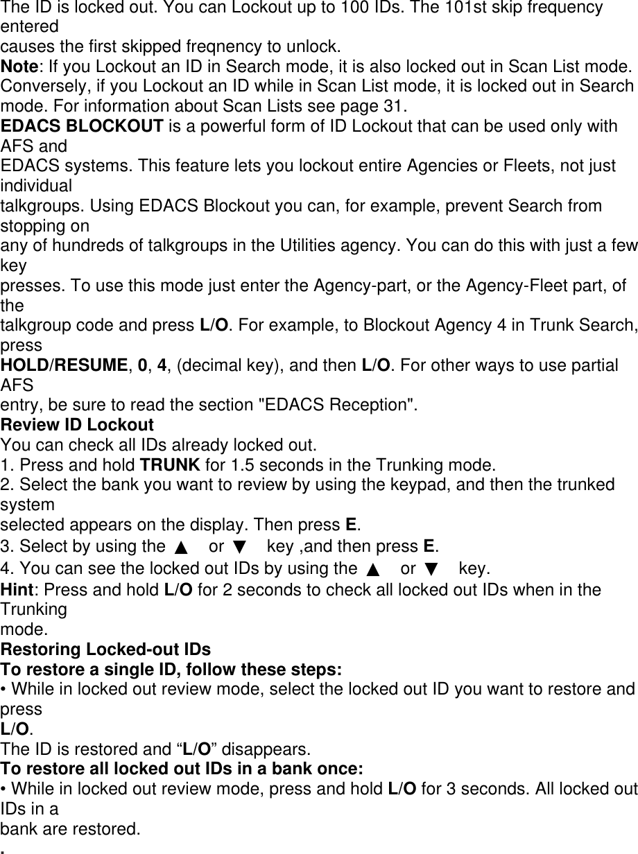
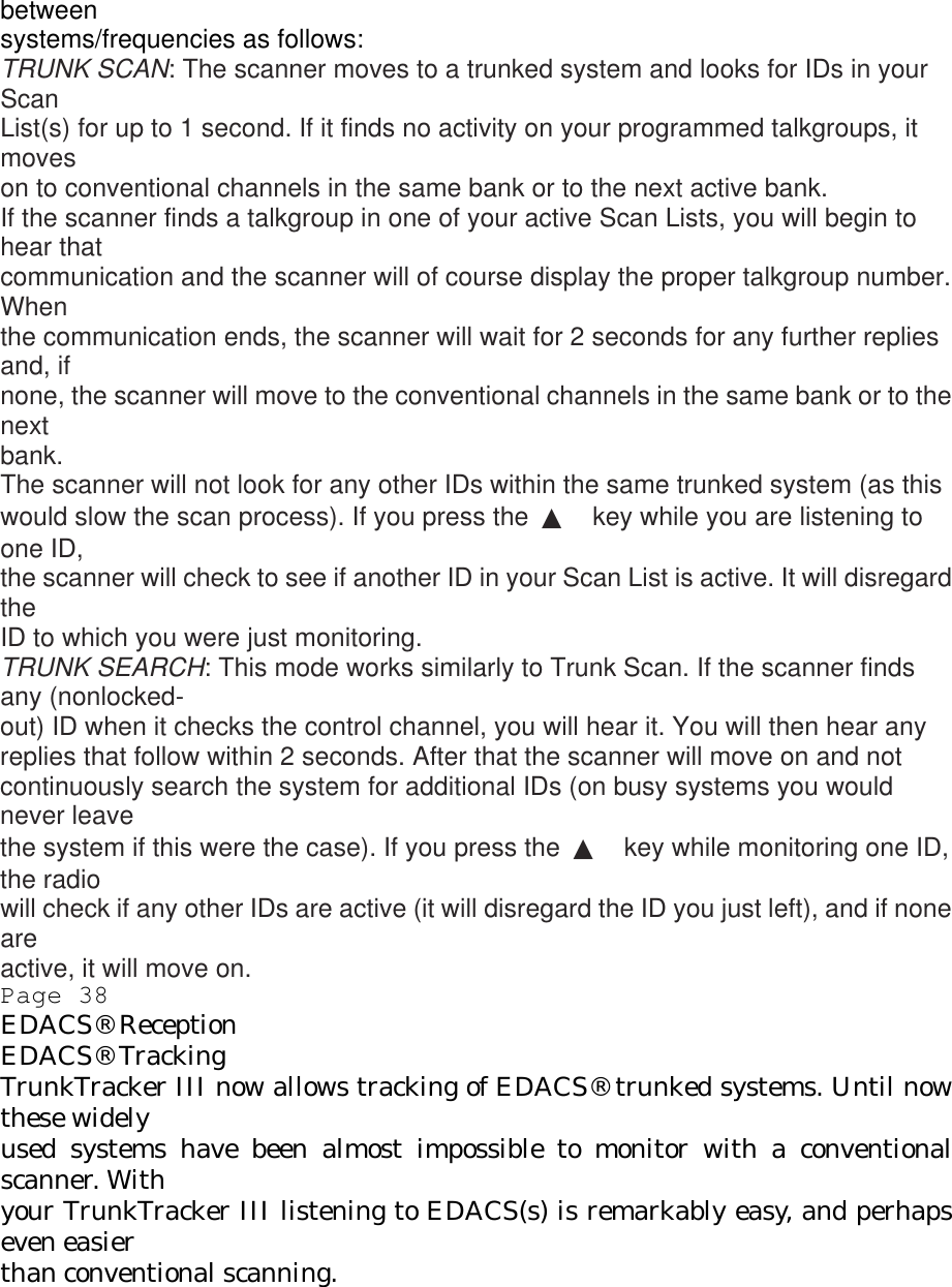
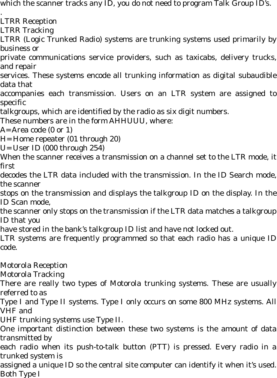
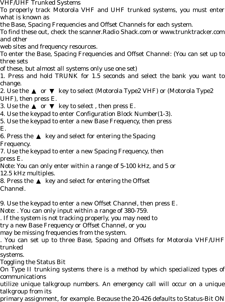
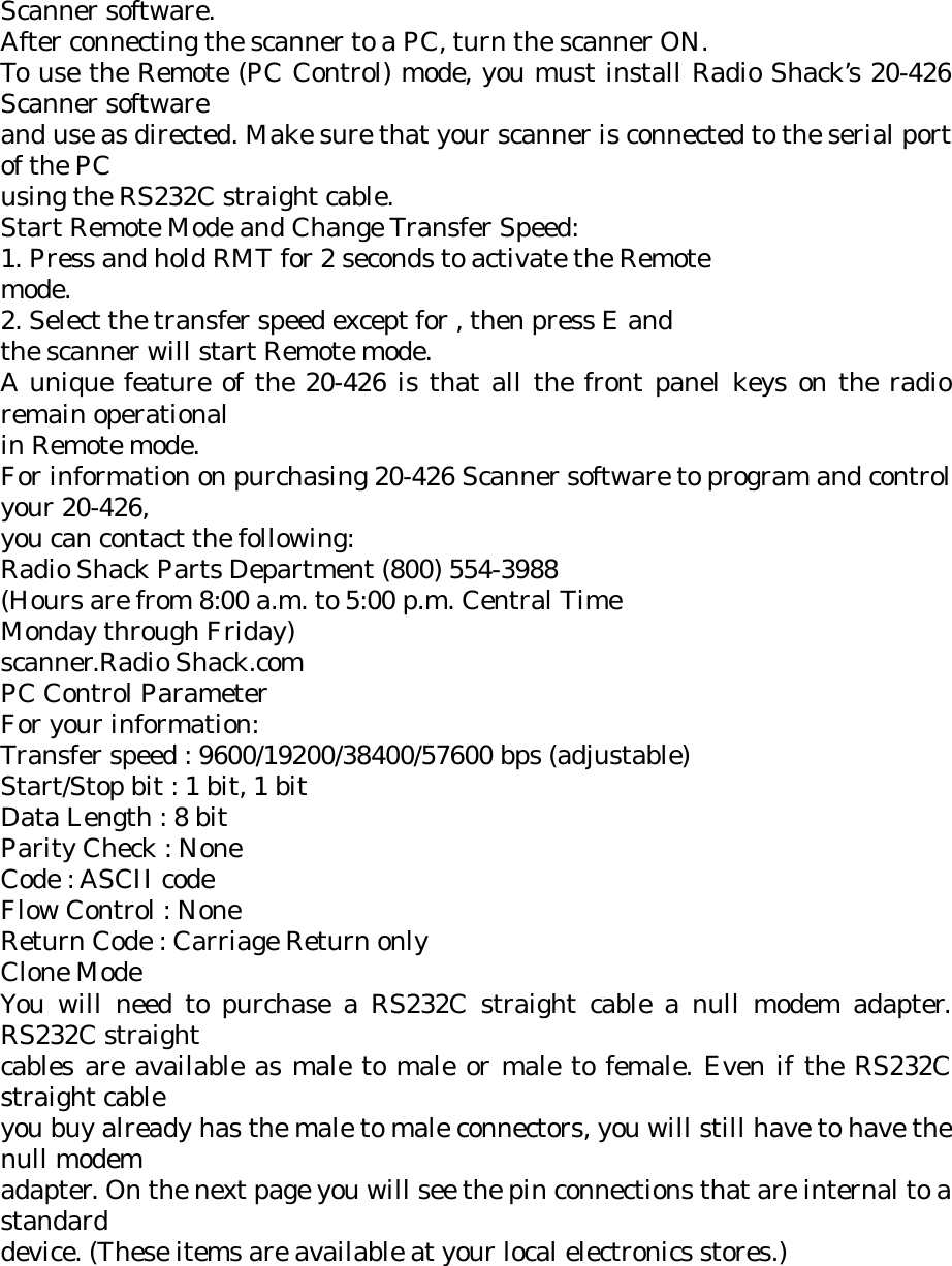
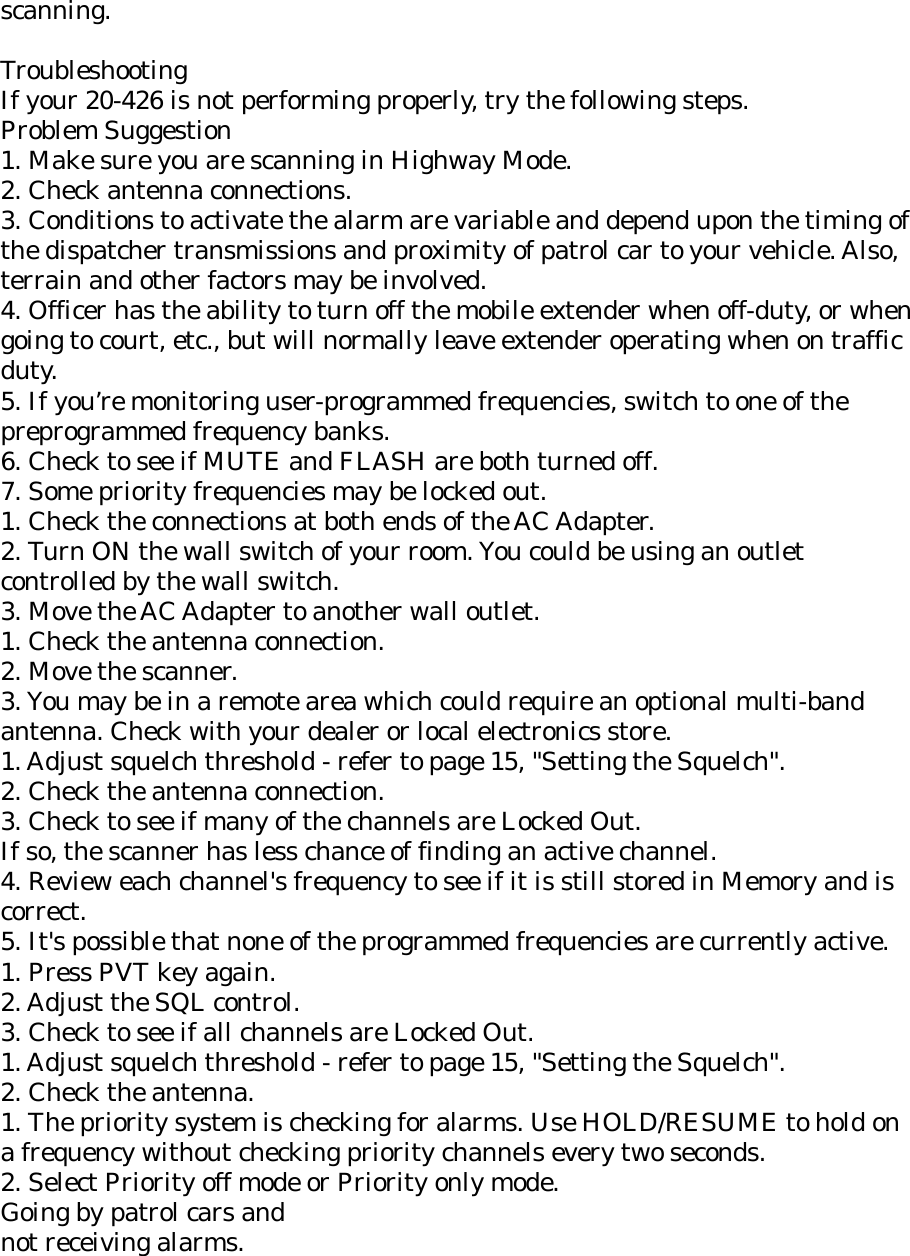
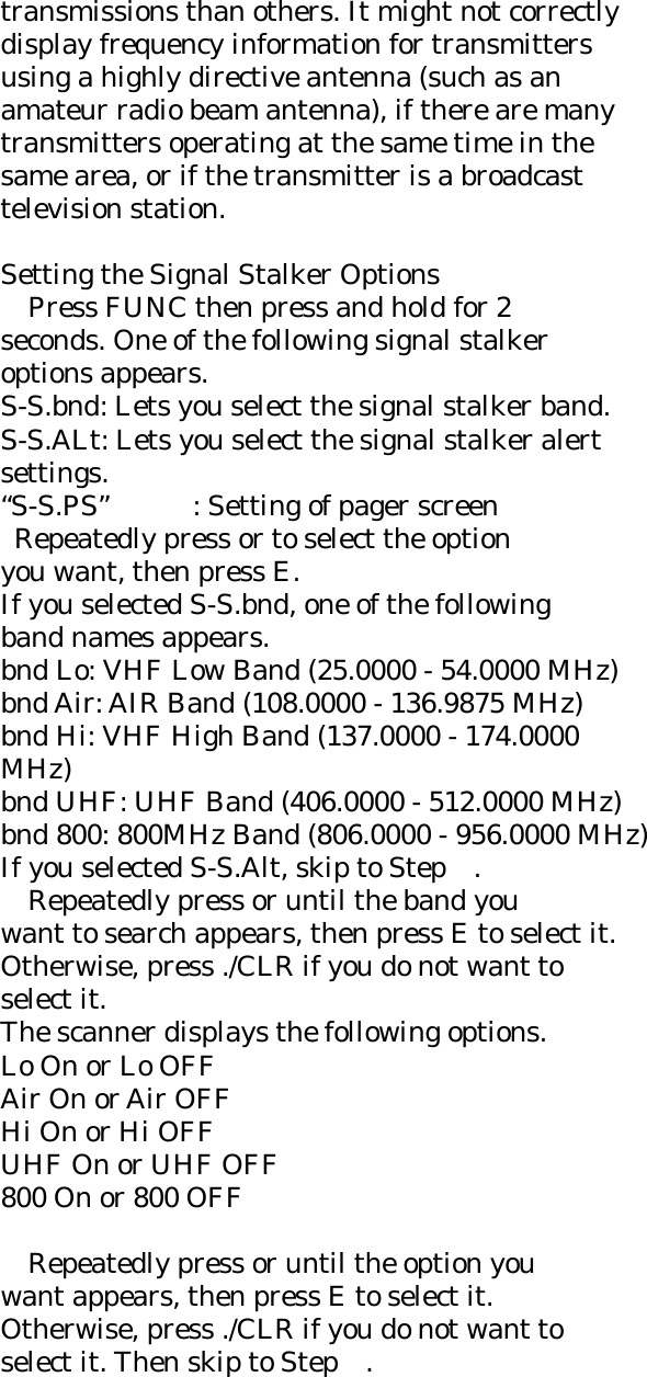
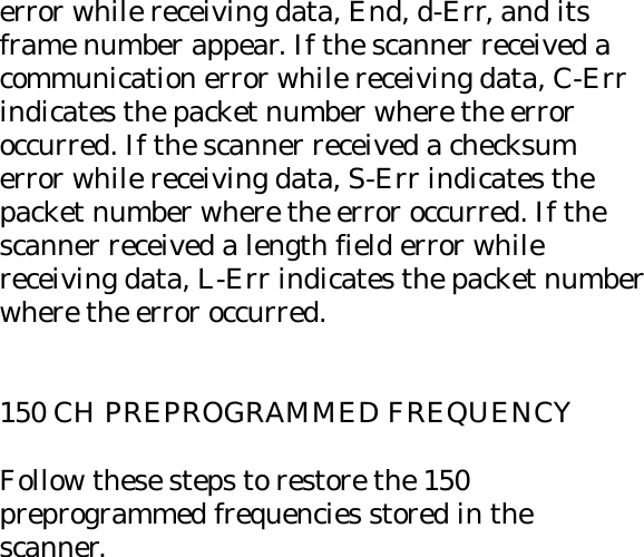
![Window Mount Antenna (included) Antenna Jack: BNC type External Jacks: External Speaker (EXT.SP.) (3.5 mm) DC 12 V Power Jack, (center is positive) Remote Control (REMOTE) Jack (DB-9) Size: 7.06 in. (W) x 6.10 in. (D) x 2.44 in. (H) 176.5mm (W) x 152.5mm (D) x 50.8mm (H) Weight: 1.1 kg (2 lbs 7 oz.) Features and specifications are all subject to change without notice. Limited Warranty RadioShack Corporation Fort Worth, Texas 76102 Cat. No. 20-426 09A04 Printed in China UBZZ01331ZZ NWR SAME During weather scanning, press [HOLD] to go to hold mode. Press F+[WX ALT] to enable NWR SAME alert. When WX alert is on, “ALERT” LED is displayed ON. And the audio mute is set on. Press F+[WX ALT] to turn off NWR SAME alert. If the scanner receives a SAME event code from the local weather service, it sounds an alert and displays the description for any alert received. And then audio mute is off. And “ALERT” LED is blinking. The scanner display in channel area the following message; Warning : “L1” Watch : “L2” Advisory : “L3” Test : “TST”](https://usermanual.wiki/Uniden-America/UB331/User-Guide-486410-Page-58.png)
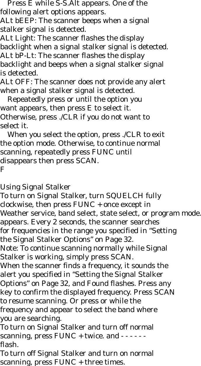
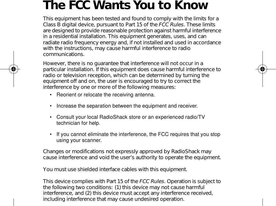
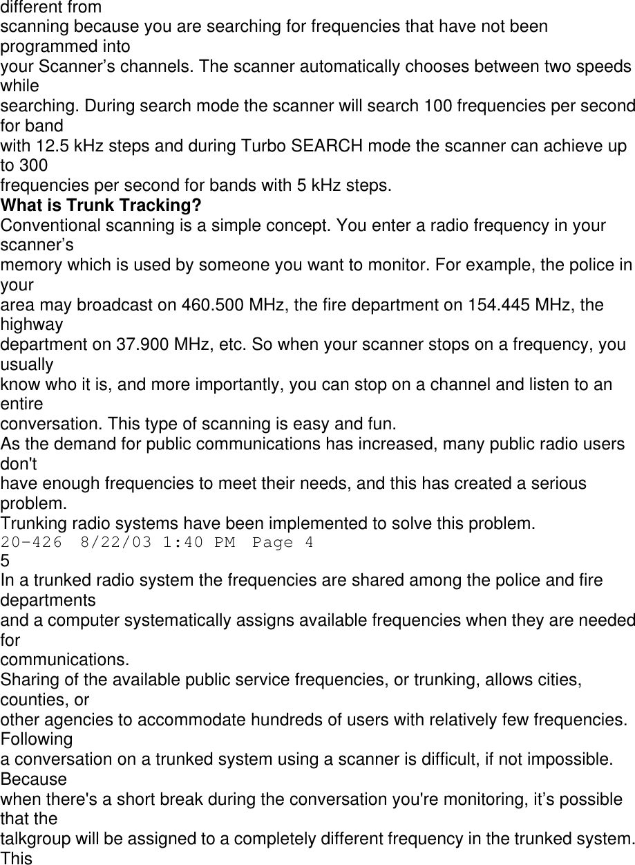
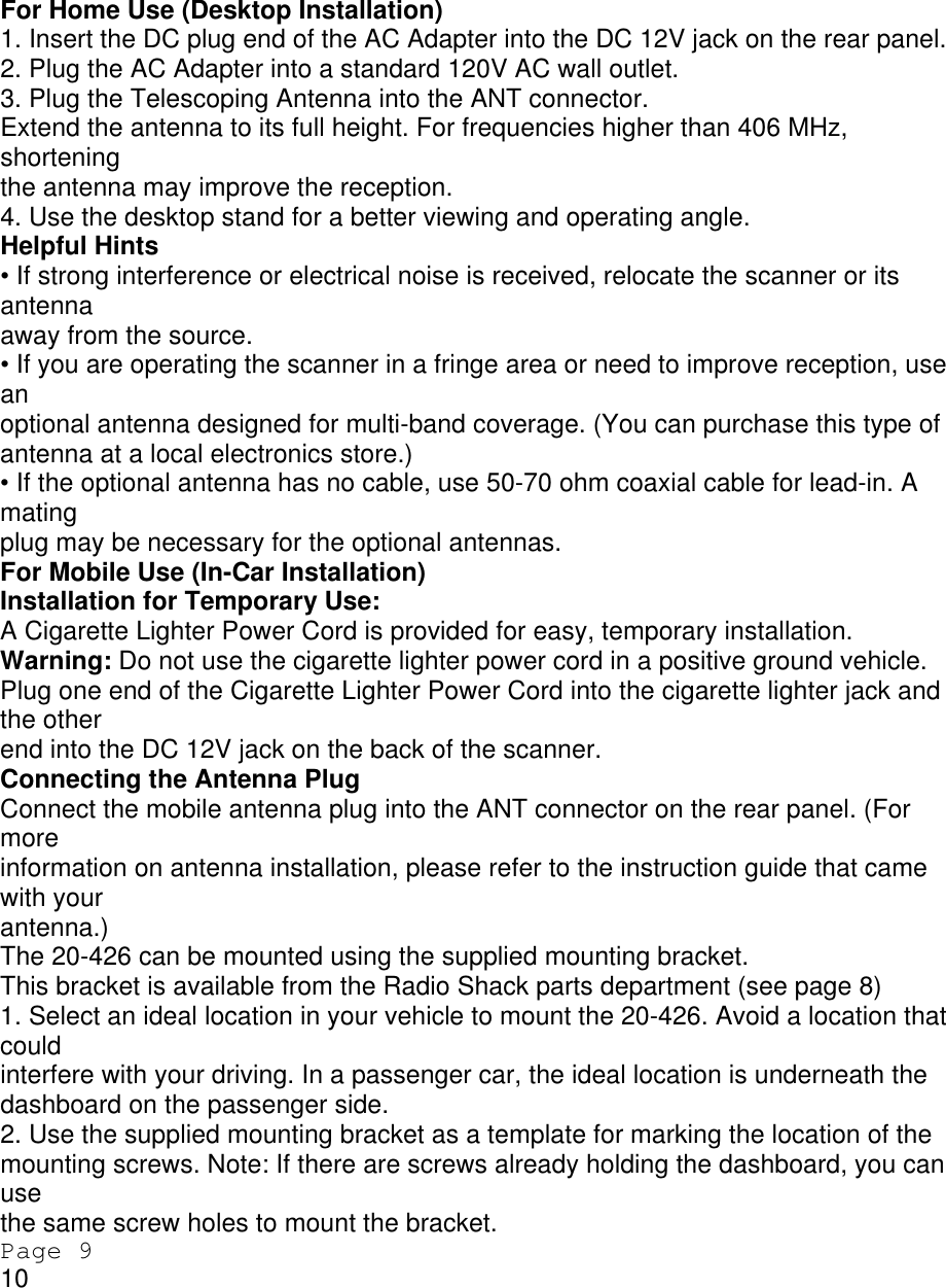
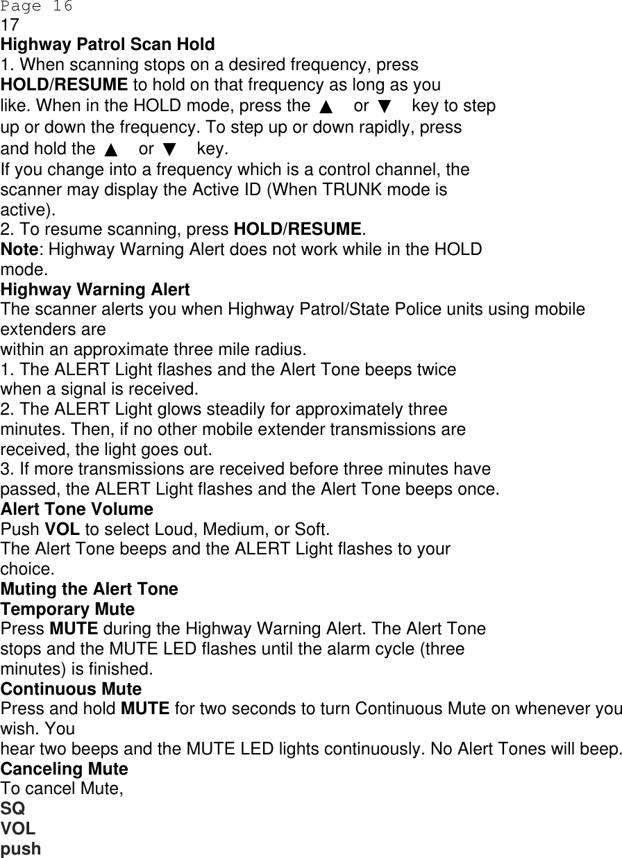
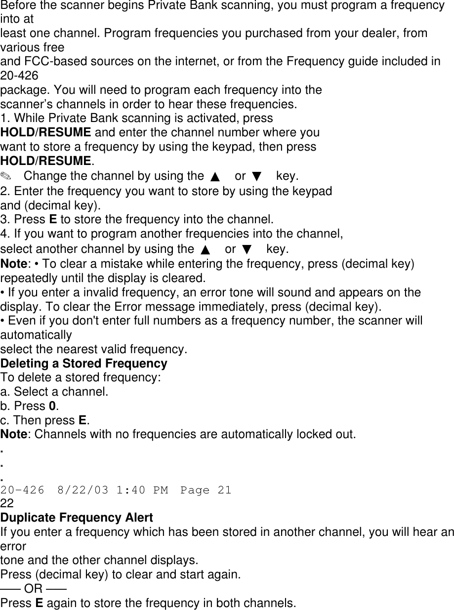
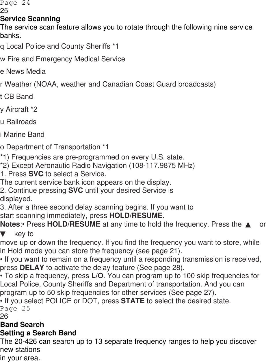
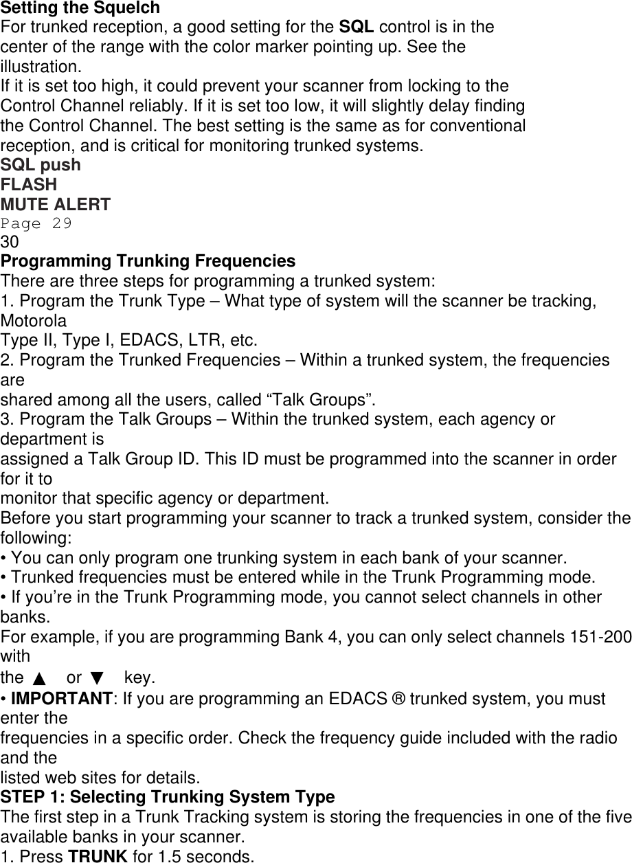
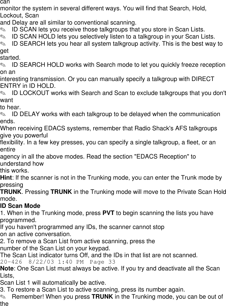
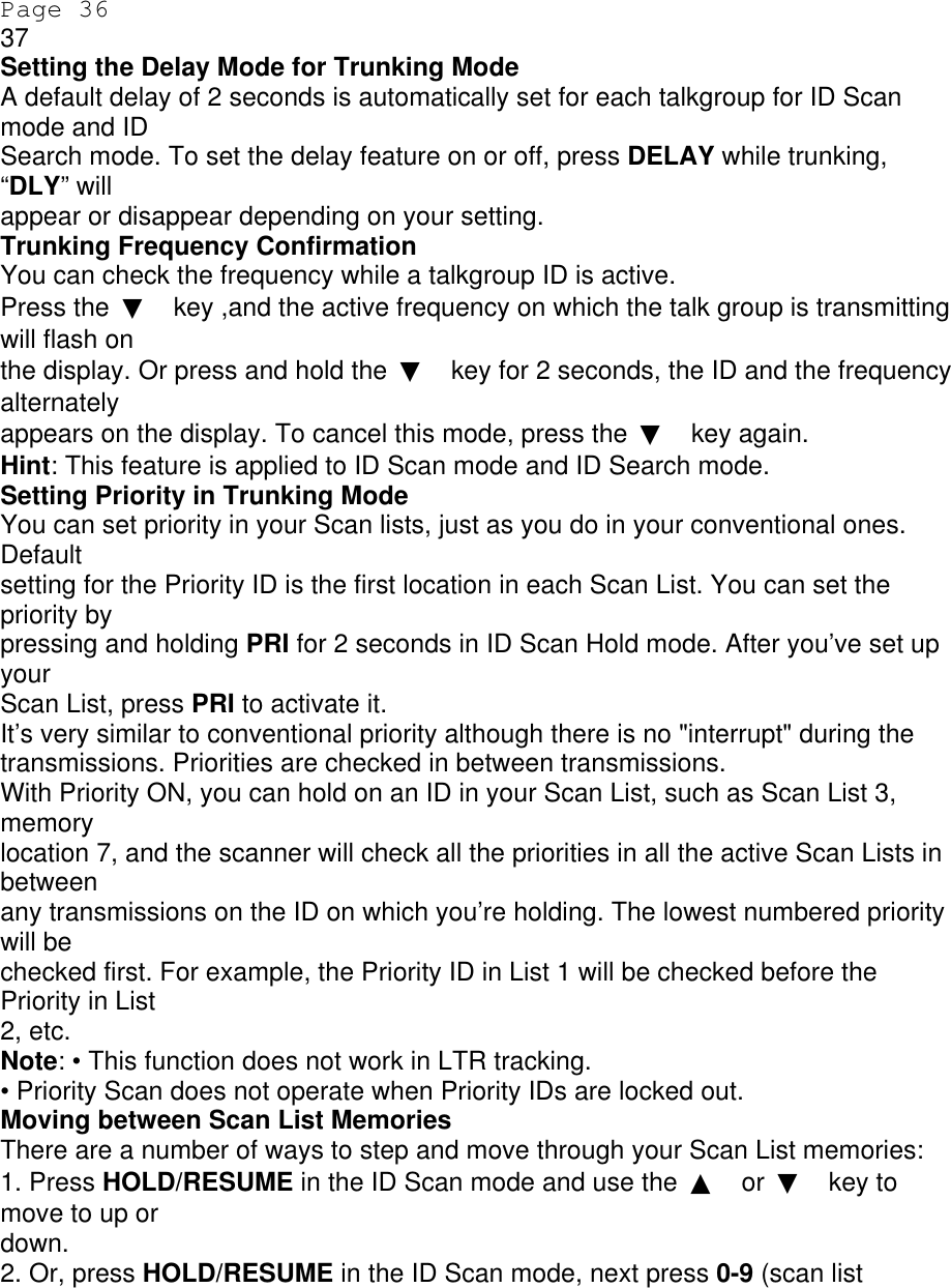
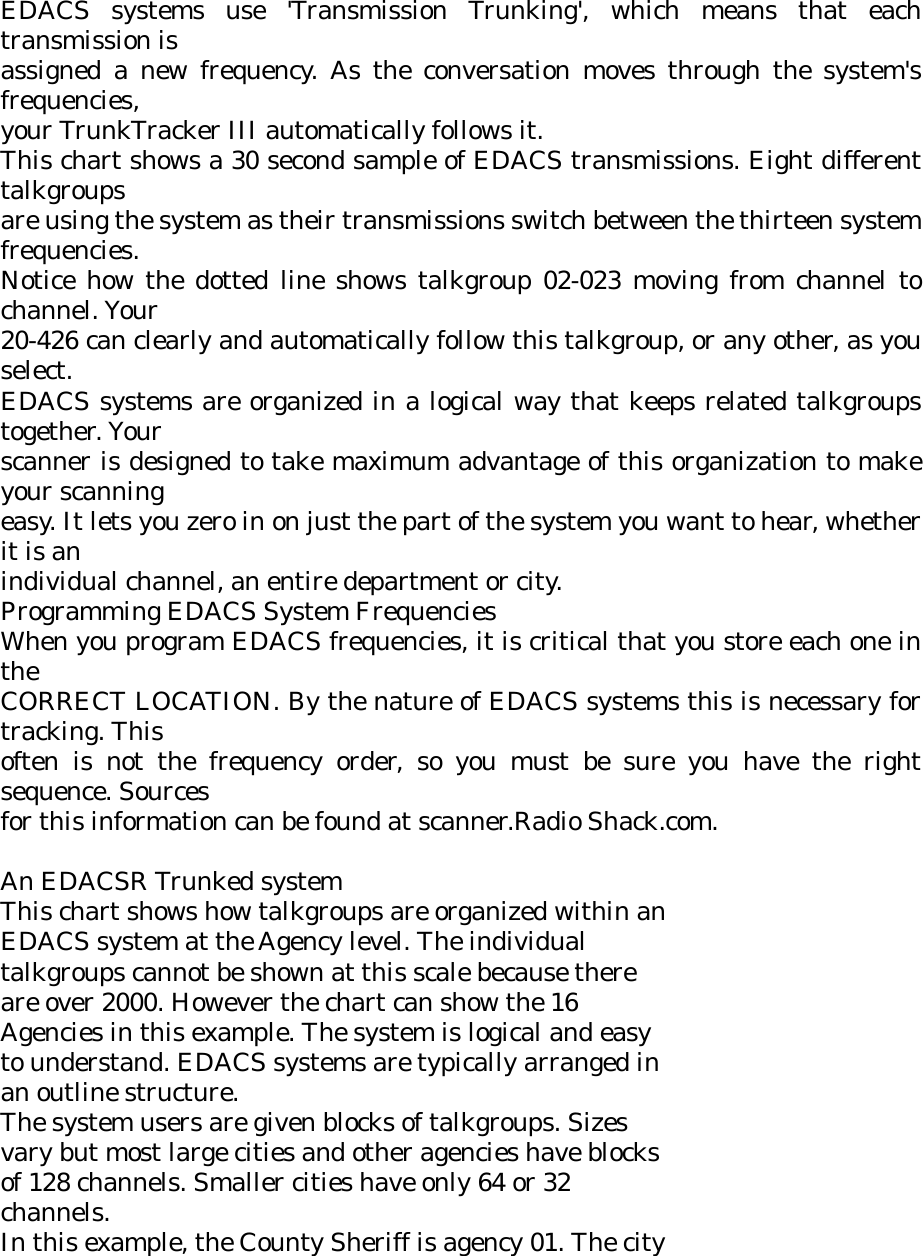
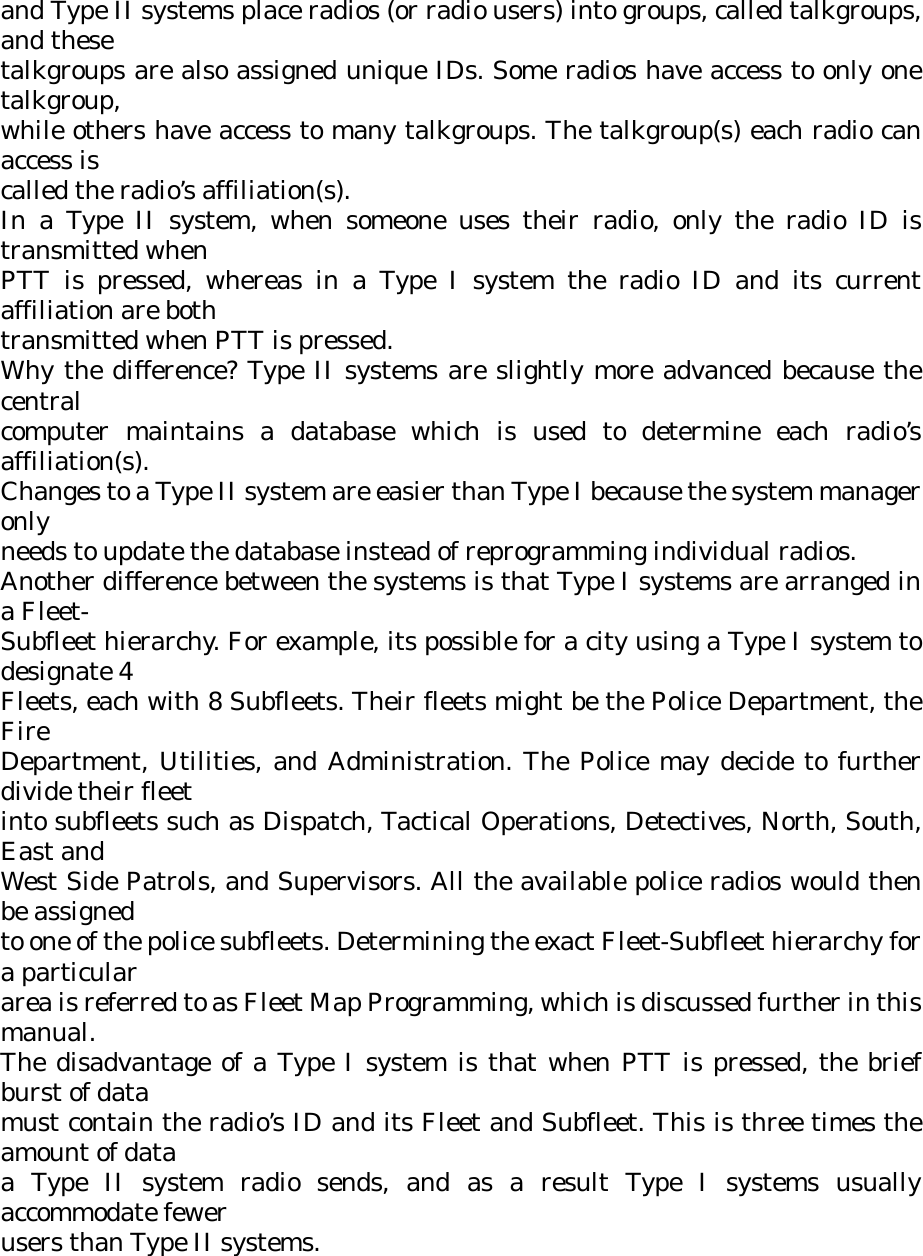
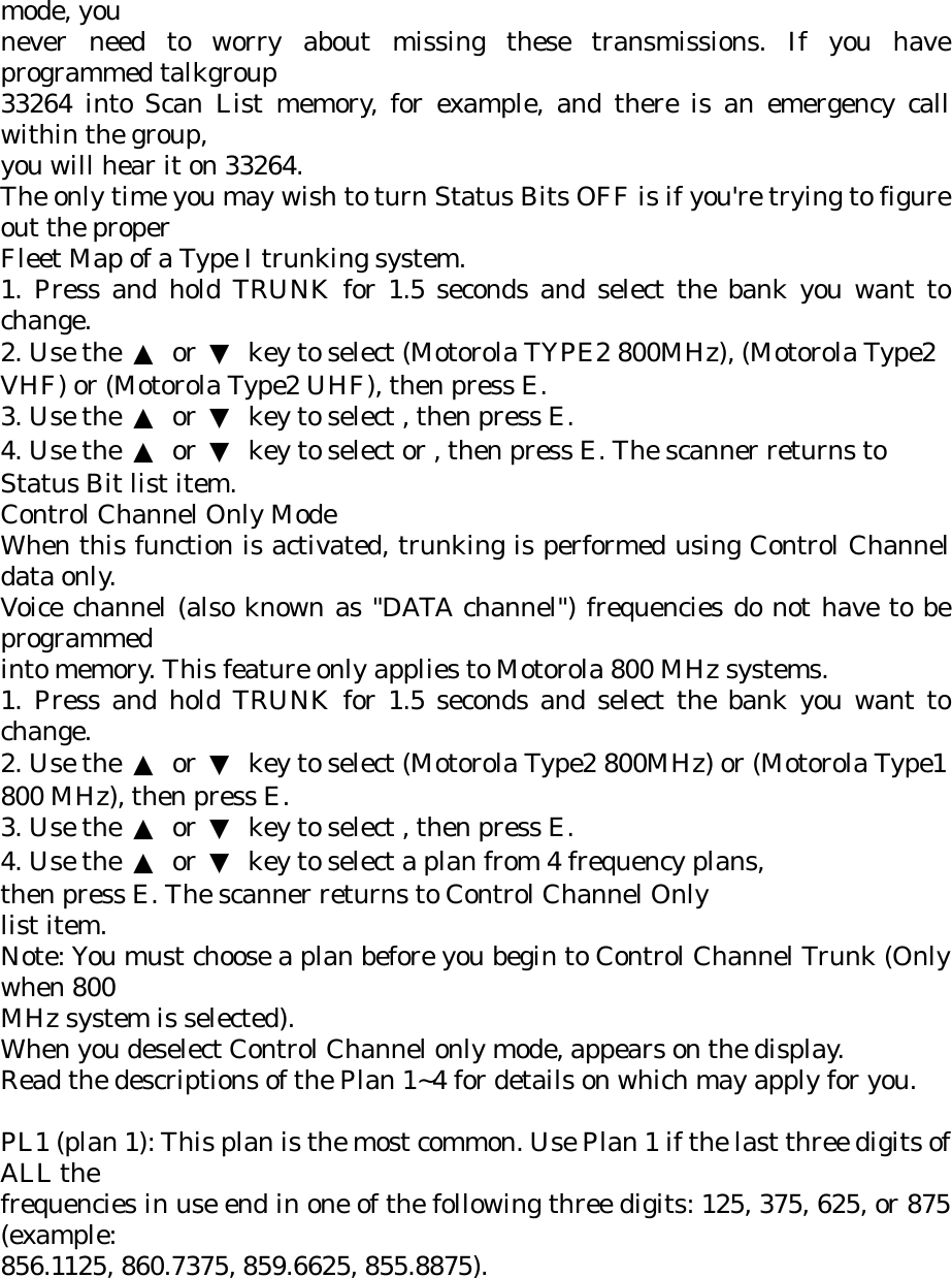
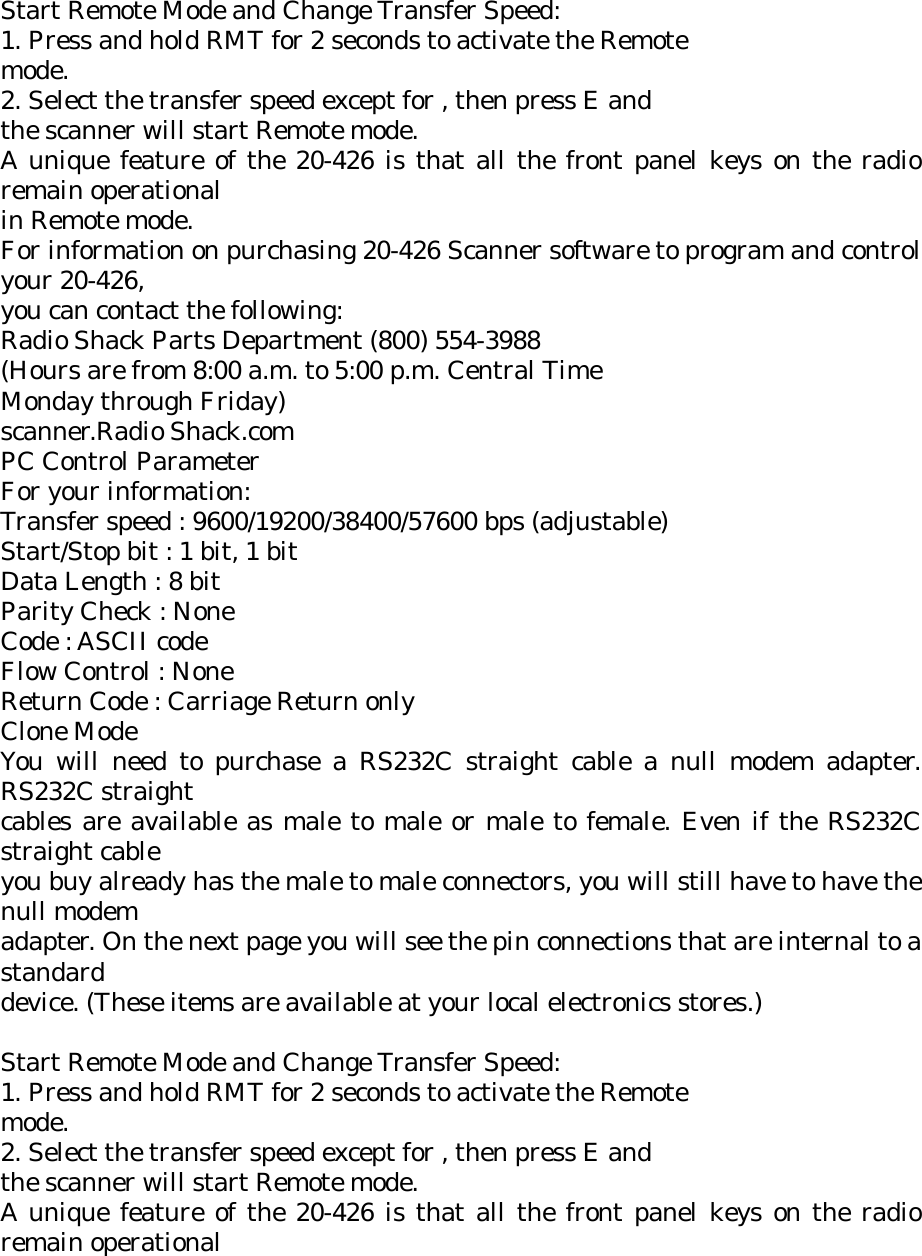
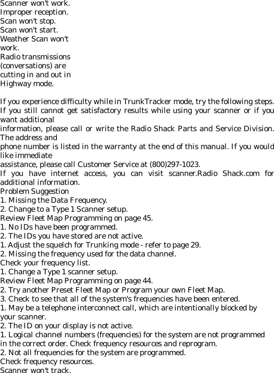
![WX alert (1050 Hz) : WXA During an alert, press any key, then an alert stops. If you do not press any key, then the scanner continues sounding the alert beep. Although alert beep (warning beep, watch beep ,advisory beep) is sounded at short intervals for 5 minutes, after that, the emergency beep will be sounded beep at intervals of 10 sec. Programming FIPS code To specify a county, SAME uses a standard established by the US Census bureau, called FIPS. The format of a FIPS code is: DSSCCC Where D = area subdivision (0=entire area) SS = State code (00=all states) CCC = County code (000=all counties) For example, the FIPS code for Tarrant County, Texas is: 048439 (48=Texas; 439=Tarrant County). Some counties are further subdivided, in which cases, the first digit will be 0 for all subdivisions in the county and each subdivision will be labeled 1-9. To program your scanner to alert you when the weather service issues an alert, you must set the scanner to the alert mode, and then leave the scanner monitoring the weather service. You cannot scan and monitor for weather alerts at the same time. To limit alerts to a specific area, you must also program in the FIPS code(s) for the area(s) you want to receive alerts for. The scanner can be set to either alert for all areas, or only the areas you have programmed. Programming FIPS To program weather alert operation: During weather scan hold mode, press F+[E], go to FIPS programming mode. If the scanner is set to alert for all FIPS. “ALLFIPS” is displayed. If the scanner is set to alert only the area you have programmed, “F1” is displayed. Press [▲] or [▼] to move FIPS code “F1” to “F15”. If FIPS code is no programmed, “------“ is displayed. Input FIPS code by numeric key. Press [./CLR] to cancel inputted FIPS code. Press [E] to store FIPS code. Press [0], [E] to clear FIPS code. “------“ is displayed. If an invalid value has been inputted, FIPS code will be cleared.](https://usermanual.wiki/Uniden-America/UB331/User-Guide-486410-Page-59.png)
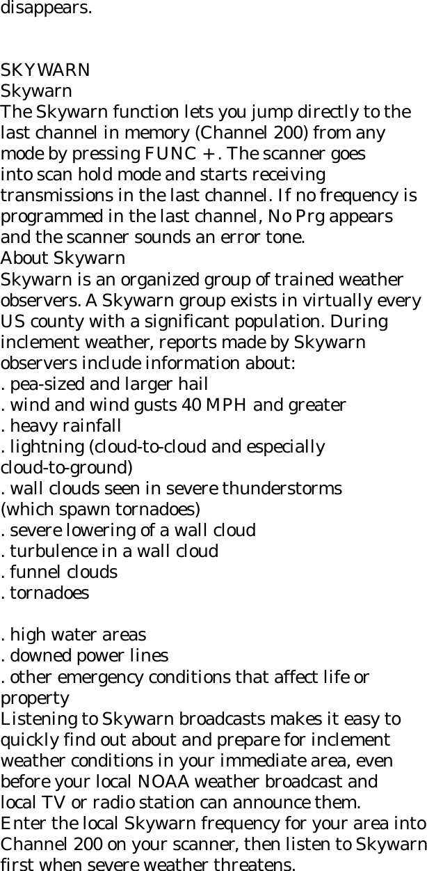
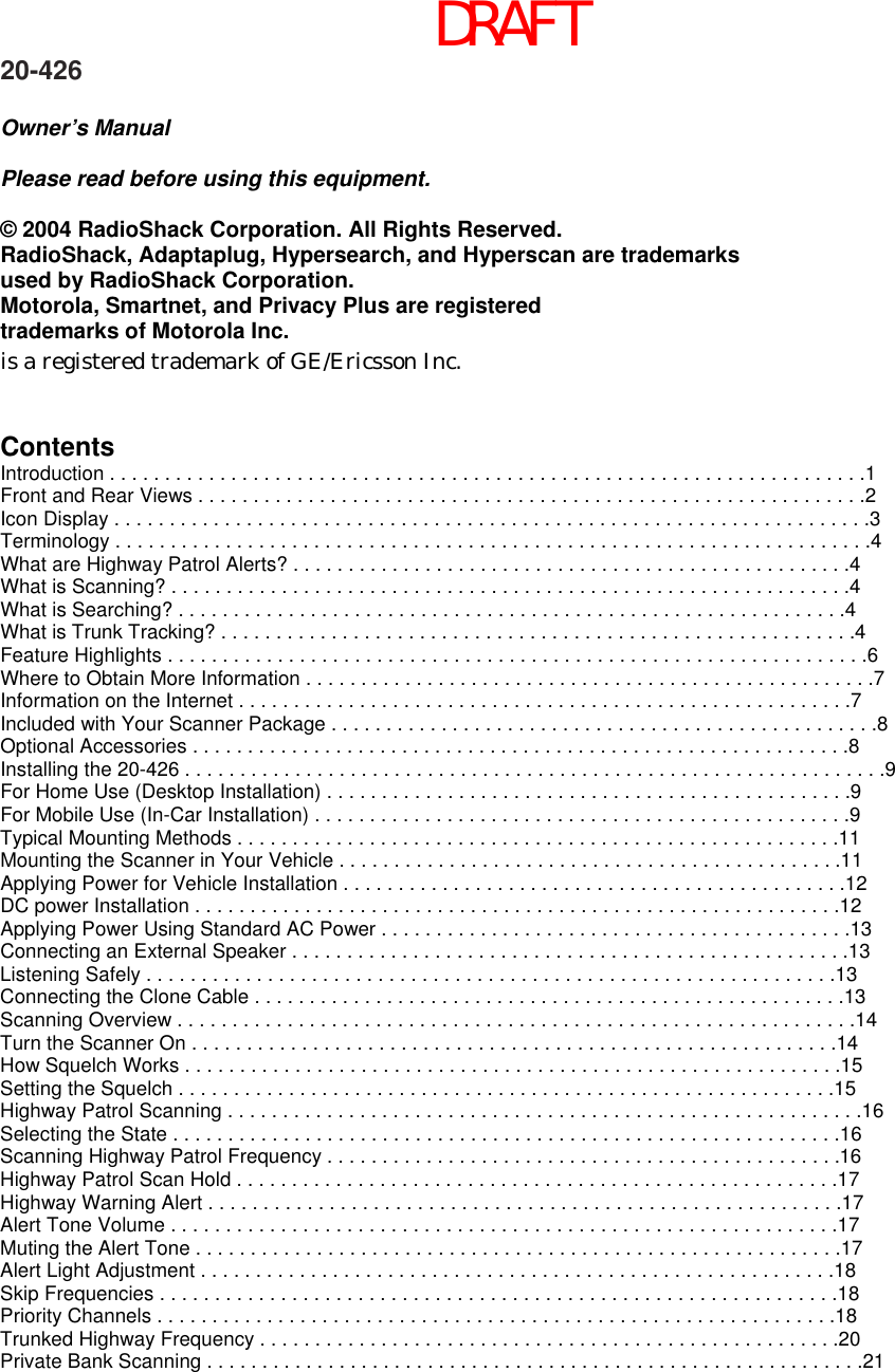
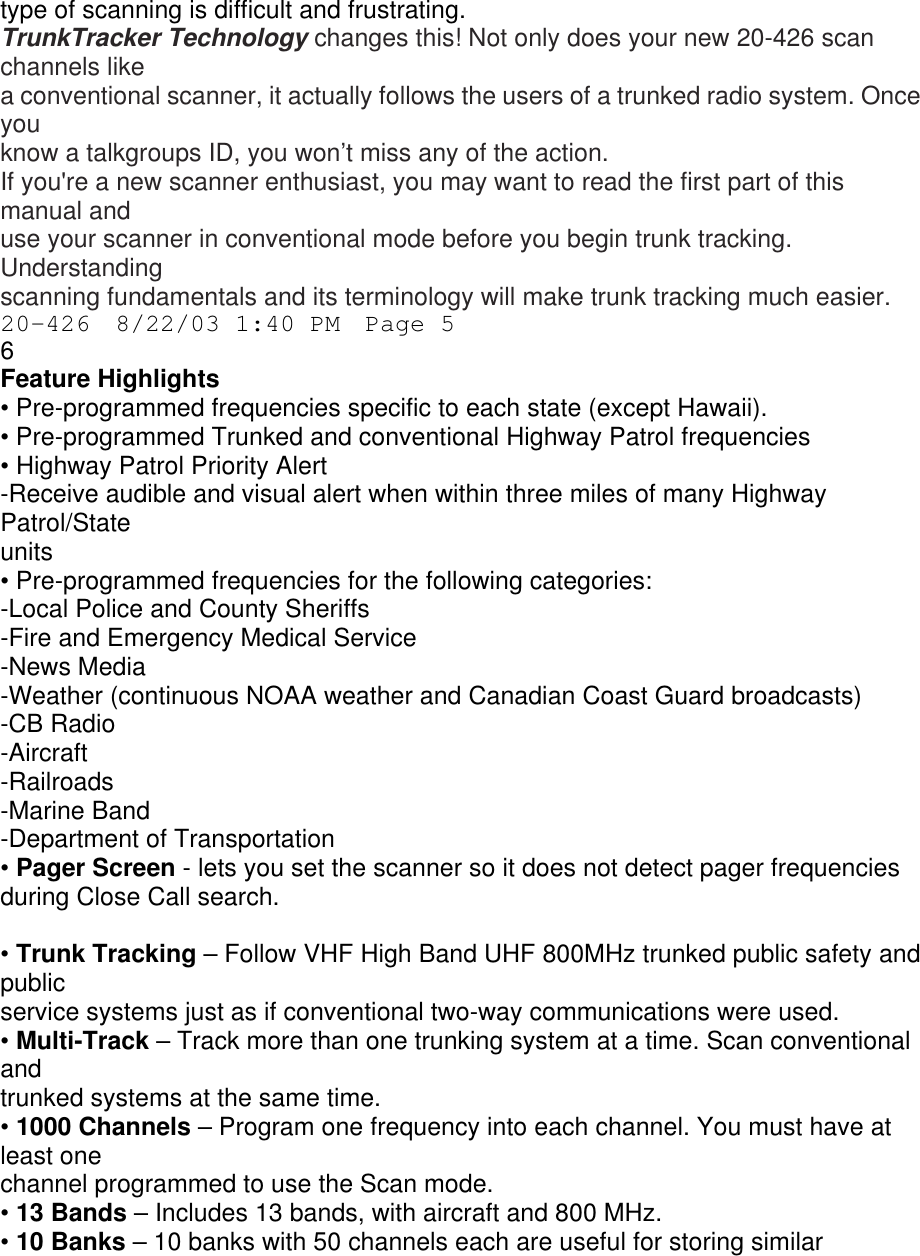
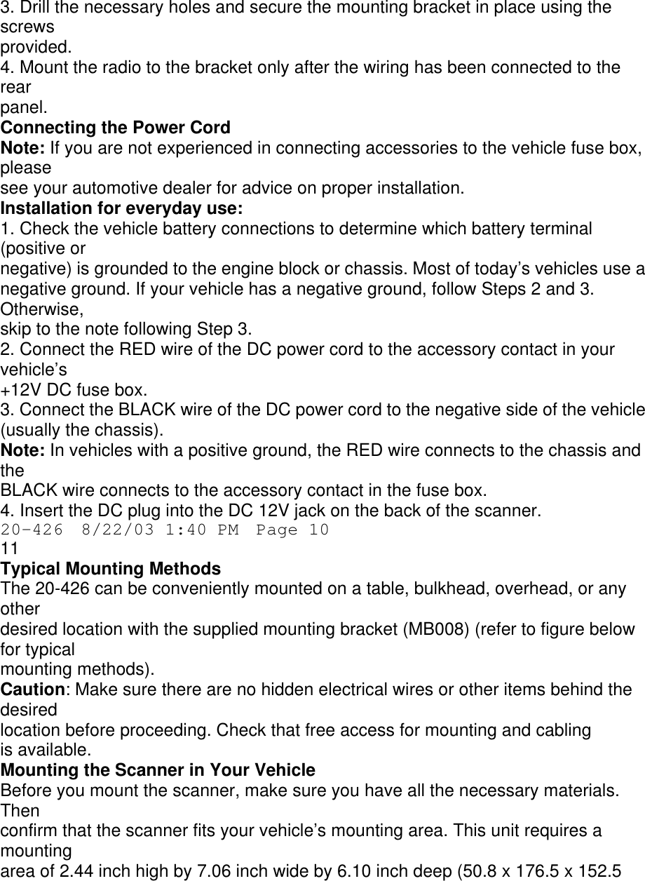
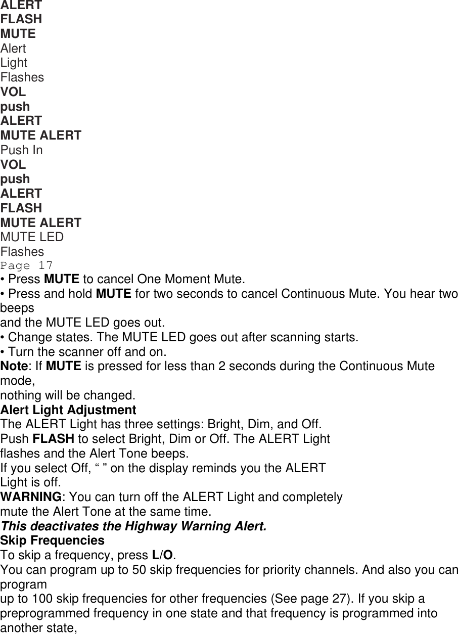
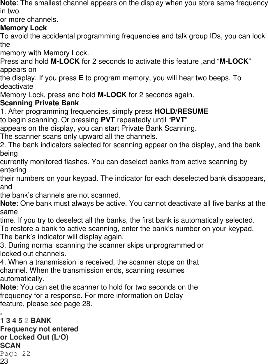
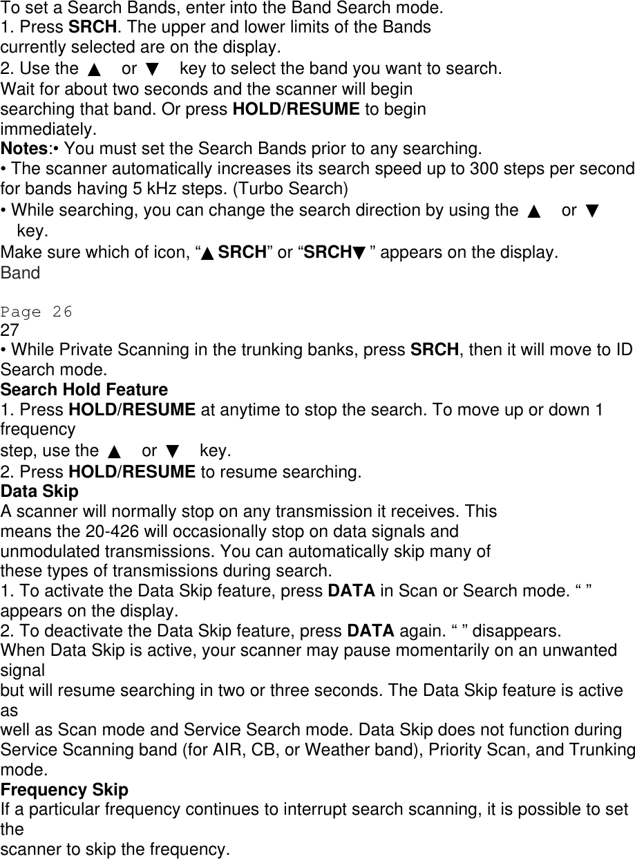
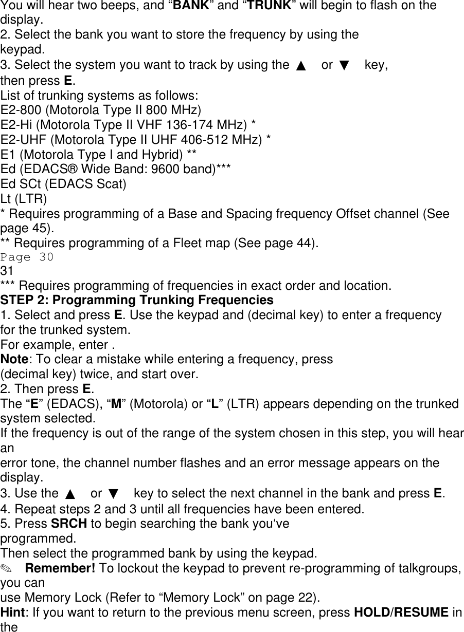
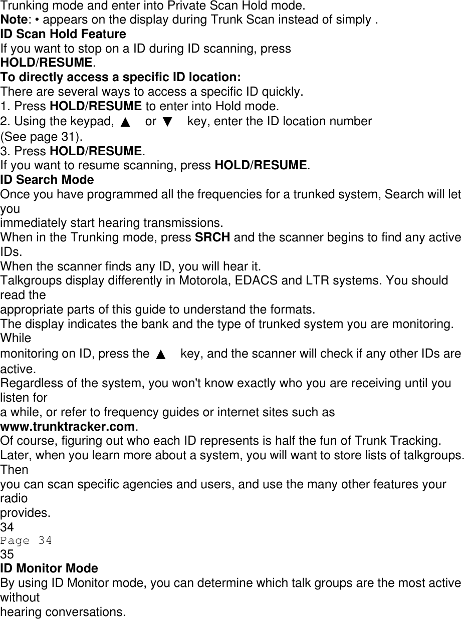
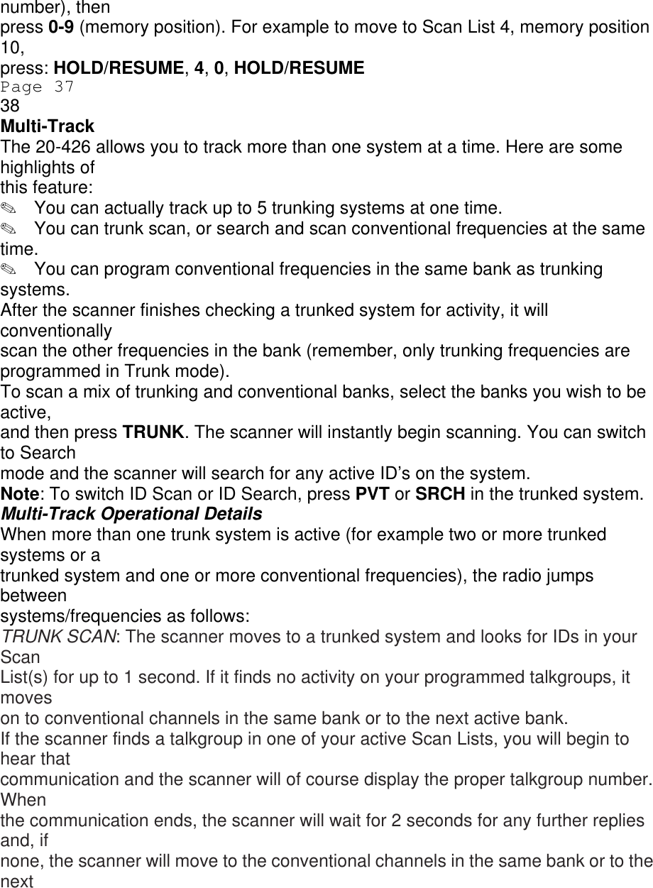
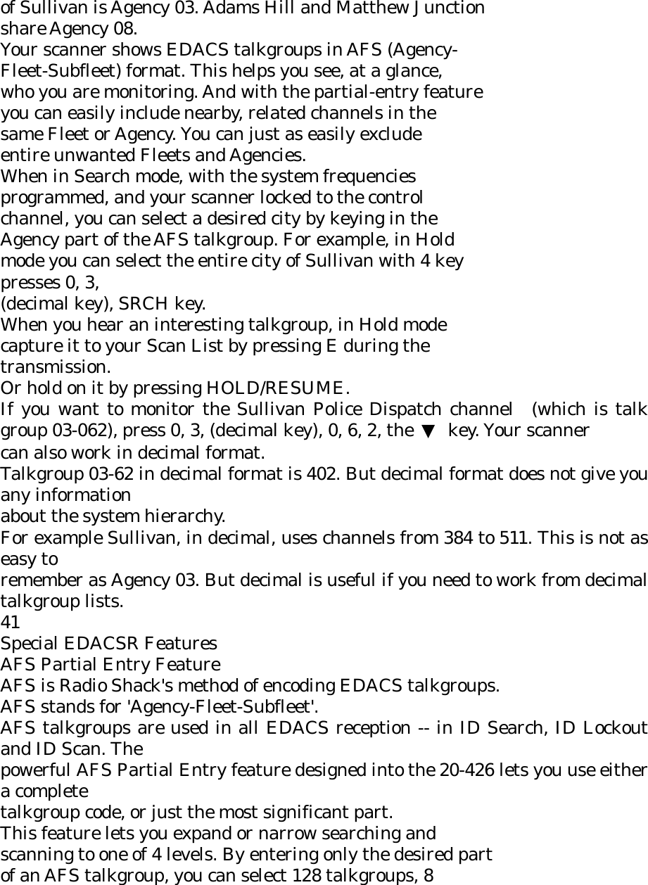
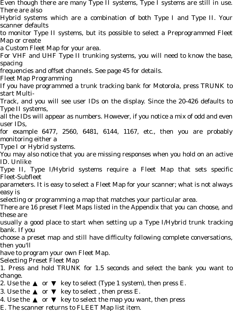
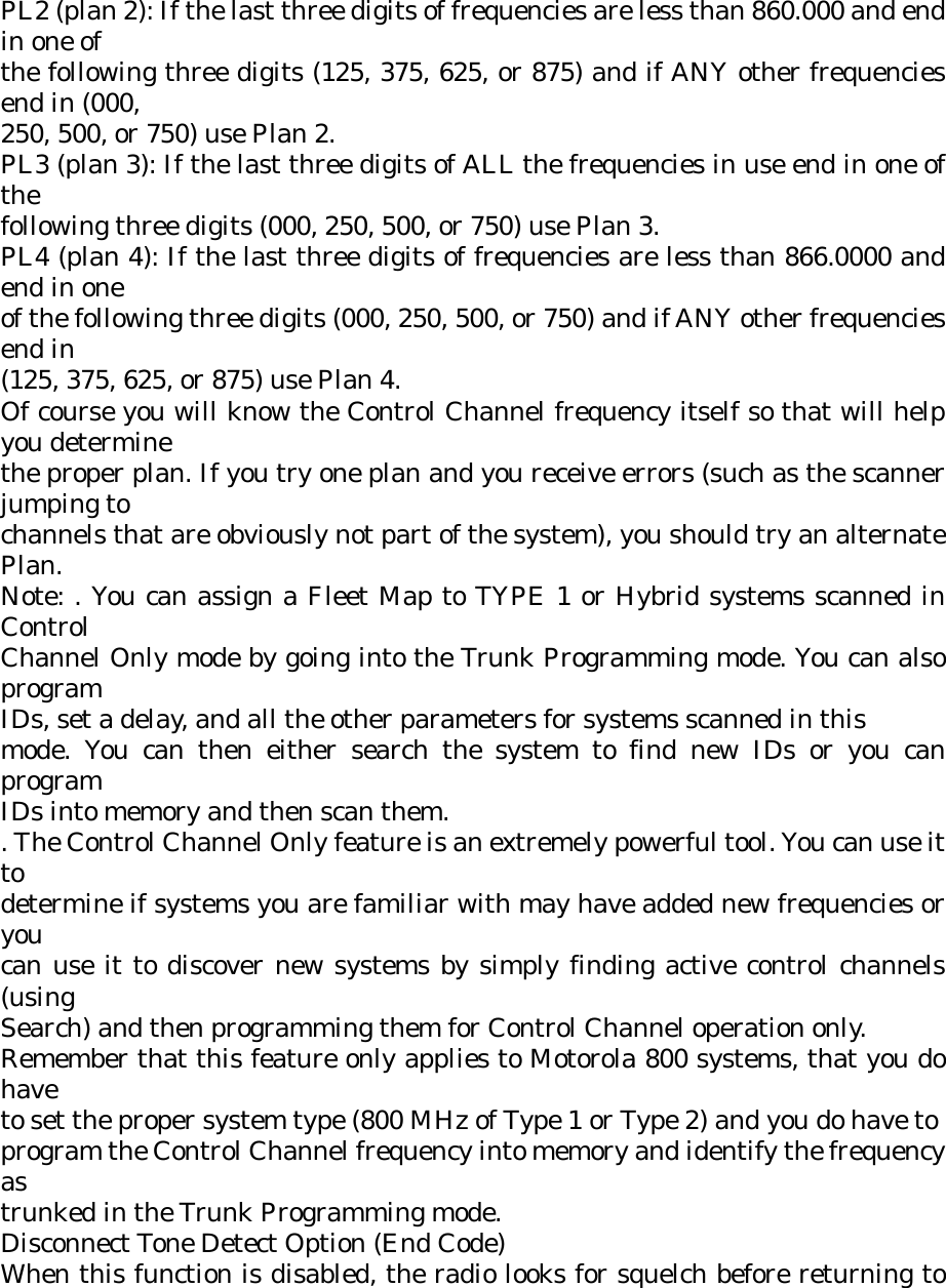
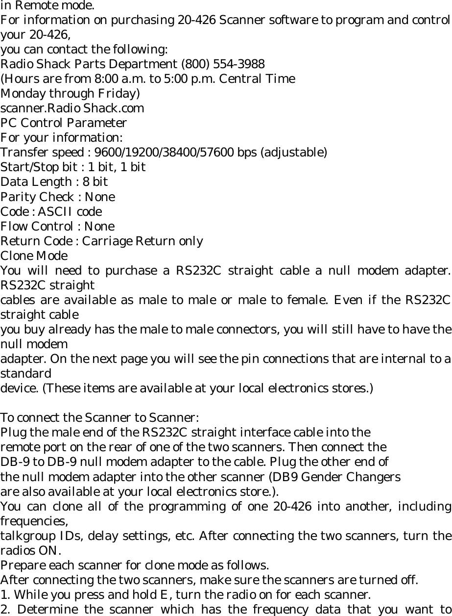
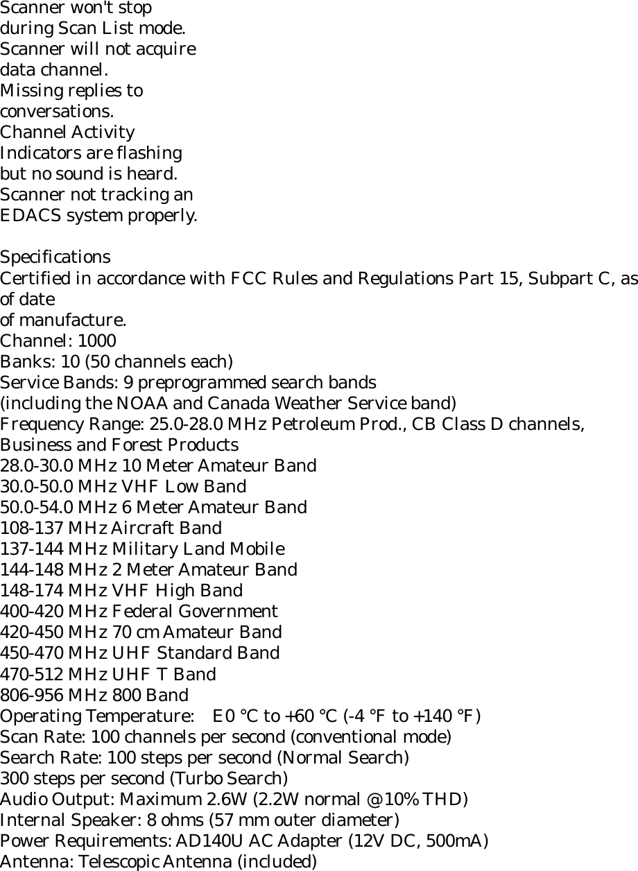
![To set to alert all FIPS, press [▲] or [▼] to move “ALLFIPS”. And press [E]. Then go to WX hold mode. To set to alert only the area you have programmed, press [▲] or [▼] to move “F1” to “F15”. And press [E]. Then go to WX hold with WX alert. Press [HOLD] to exit this mode. SIGNAL STALKER Signal Stalker Your scanner's Signal Stalker feature lets you set the scanner so it detects then displays the frequency of a nearby strong radio transmission. You can set the scanner so Signal Stalker works "in the background" while you are scanning other frequencies, turn off normal scanning while Signal Stalker is working, or turn off Signal Stalker and use the scanner normally. You can set the scanner so it alerts you when Signal Stalker finds a frequency. You can also set the frequency band where you want the scanner to look for transmissions. Notes: . Signal Stalker works well for locating the source of strong local transmissions such as mobile and handheld two-way radios in areas with no other strong transmission sources. However, if you are in an area with many transmission sources (such as pager radio transmitters, multiuse radio towers, traffic control devices, etc.), Signal Stalker might not find the transmission you are searching for, or it might find a transmission other than the one you are searching for. You can screen unwanted transmissions by pressing FUNC + L/O to lock them out. See “Locking Out Frequencies” on Page 49 for more information. . Signal Stalker cannot detect satellite dishes or any transmitter with a frequency above or below the frequency ranges listed under “Setting the Signal Stalker Options” on Page 32. . Signal Stalker works better with some types of](https://usermanual.wiki/Uniden-America/UB331/User-Guide-486410-Page-60.png)