Uniden America UT401 CB Transceiver User Manual PRO401HH
Uniden America Corporation CB Transceiver PRO401HH
Contents
- 1. Users Manual
- 2. CB Radio Rules Manual
- 3. CB Rules
- 4. PRO401HH User Manual
PRO401HH User Manual
Sheet 2 Page 1
xxxxxxxxxxx(0)Printed in Vietnam

Sheet 1 Page 2
INTRODUCTION
The PRO401 radio is a mobile radio designed for use in the Citizens Band
(CB) Radio Service. It will operate on any of the 40 AM frequencies authorized
by the Federal Communications Commission (FCC). Your radio features a
superheterodyne circuit with Phase Locked Loop techniques to assure precise
frequency control.
► Condenser microphone.
► Ceramic lter: Delivers greater selectivity and reduces adjacent channel
interference.
► AGC (Automatic Gain Control) for a constant sound level.
► Automatic modulation control for a constant audio transmit modulation
level.
► Low distortion IC audio circuit.
► Automatic noise limiter to reduce pulse noise.
► “HI-LO” switch: Adjusts output power.
► Antenna with BNC connector.
► Jack for external power source and battery charger.
► Do not expose the PRO401HH to water or extreme temperatures.
► Do not leave batteries installed over a long period of time as leakage may
occur and cause damage to the radio.
► Never use different batteries from the ones suggested.
► Never use harsh chemicals to clean this radio. Use a damp soft cloth.
FCC PaRT 15 COmPlIaNCe INFORmaTION
This device complies with FCC Part 15 standard(s). Operation is subject to
the following two conditions: (1) this device may not cause interference, and
(2) this device must accept any interference, including interference that may
cause undesired operation of the device.
Changes or modications to this product or use of accessories not expressly
approved by Uniden, or operation of this product in any way other than as
provided in the Uniden Owner’s Manual could void your authority to operate
this product.
A complete Owner’s Manual in French can be downloaded from http://www.
uniden.com/.
Sheet 1 Page 3
Cet appareil est conforme la norme d’Industrie Canada exempt de licence
RSS (s). Son fonctionnement est soumis aux deux conditions suivantes : (1)
cet appareil ne peut pas provoquer d’interférences, et (2) cet appareil doit
accepter toute interférence, y compris les interférences qui peuvent causer un
mauvais fonctionnement de l’appareil.
Tous les changements apportés à cet appareil, s’ils ne sont pas expressément
approuvés par Uniden ou toute utilisation de celui-ci d’une autre manière
que celle décrite dans ce guide peut annuler votre autorisation de le faire
fonctionner.
Un guide d’utilisation en français peut être téléchargé à l’adresse suivante :
http://www.uniden.com/.
You can get answers 24/7 at our website: www.uniden.com.
have a question or problem Customer Care Line* 800-297-1023
need a part or accessory Parts Department* 800-554-3988
need special assistance due
to a disability Accessibility Help Line 800-874-9314
(voice or TTY)
*During regular business hours, Central Standard Time. Visit our website for detailed
business hours.
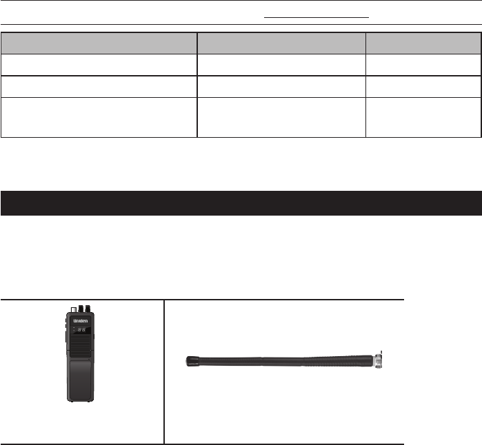
INClUDeD IN YOUR PaCKaGe
If any of these items are missing or damaged, immediately contact your place
of purchase or Uniden’s Parts Department.
TX
BATT. LOW
EXT PWR
PRO401HH
MIC
MIC
HI
PRO401HH Radio
Antenna
Sheet 1 Page 4
DC Power Input
Other printed materials
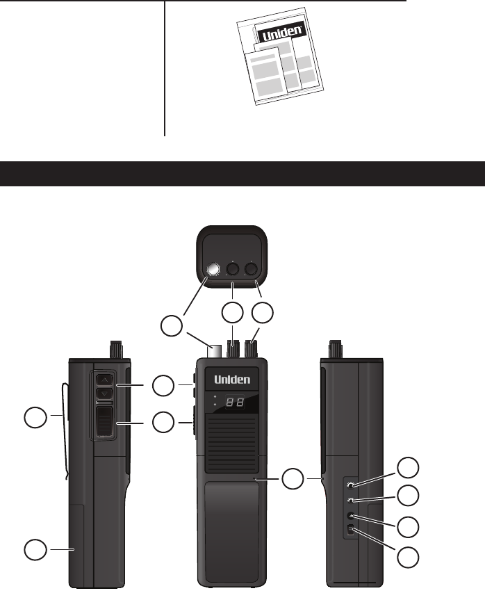
PaRTS OF THe RaDIO
1
2
NOTE: A switch inside the compartment lets you select rechargeable or
Alkaline batteries.
3
Selects which channel the radio will transmit or receive on.
4
Allows you to transmit.
SQUELCH VOLUME
SPKR
MIC
DC 13.8V
CHARGE
HI
LOW
PTT
PTT
TX
BATT. LOW
EXT PWR
PRO401HH
MIC
MIC
HI
1
3
2
5
4
10
9
8
7
6
12
11
Sheet 1 Page 5
5
Connect the detachable antenna to this jack.
6
Adjusts the level at which the radio squelches or suppresses weak radio
signals. To lter out weaker signals and background noise, turn the knob
clockwise to increase the squelch level. To decrease the squelch level so
you can hear weaker radio signals, turn the knob counter-clockwise.
7
Powers on the radio and adjusts the volume.
8
Speak into the microphone when transmitting.
9
Connects to an external speaker (not includerd). The internal speaker is
disabled.
10
Connects to an external microphone (not included).
11
Provides power to the unit. you can use external power sources such as
a car battery to power the unit and to recharge the Ni-Cd rechargeable
batteries.
12
Select a power output level for transmission.
NOTE: FCC rules reserve Channel 9 for motorist assistance and other
emergency communications. Channel 9 should only be used in situations
where there is immediate danger to the safety of individuals or the
protection of property.
Make sure you have read and understood part 95 of the FCC rules and
regulations before using the transmitter.

Sheet 1 Page 6
SeT UP
Install the included rubber antenna onto the radio.
The PRO401HH can also use any type of 50 Ω / 27 MHz band antenna.
Although a telescoping antenna might provide better transmission and
receiving, it is not as compact or easy to use as the antenna included in the
package.
Your PRO401HH can operate on DC power or batteries.
DC Power
1 Plug the DC power coverter into the PRO401HH.
2 Plut the other end into your vehicle’s cigarette lighter/DC power conversion
plug.
3 The red power LED is steady on when the unit is connected to external
power (not batteries).
WARNING! DO NOT connect this equipment to a power supply if you are
not absolutely certain of the grounding type!
Battery Power
You can use either 9 non-rechargeable alkaline batteries or 9 rechargeable Ni-
CD batteries with this unit.
1 Open battery cover.
2 Set the internal switch to match the battery type you are using (either
alkaline or rechargeable (Ni-CD) batteries.
3 Insert the 9 batteries.
4 Close battery cover.
5 The red power LED is steady on.
The red LED blinks when battery power is low. Replace/recharge the batteries
or connect the radio to a power source.

Sheet 2 Page 7
OPeRaTION aND maINTeNaNCe
Turning the
radio on
Turn the Volume knob clockwise until it clicks and the display backlight
comes on.
Turning the
radio off
Turn the Volume knob counter-clockwise until it clicks and the display
backlight turns off.
Selecting a
channel
Press the Channel UP or DOWN button on the side to move up or down the
channel list.
Changing the
volume
Turn the Volume knob clockwise to increase the volume; turn it counter-
clockwise to decrease the volume.
Transmitting
– Tune the radio to the channel you want to transmit on, and listen to make
sure the channel is clear.
– Press and hold the PTT button.
– Hold the microphone about 2 inches away from your mouth and speak in a
normal voice.
– Release the PTT button to listen for a response.
NOTE: Make sure you have read and understood part 95 of the FCC rules
and regulations before using the transmitter.
The “10” code allows you to communicate easier in noisy environments. The
following table lists some of the most common codes and their meaning.
10-1 Receiving poorly
10-2 Receiving well
10-3 Stop transmiting
10-4 OK - Understood
10-6 Busy - Stand By
10-7 Out of service - Leaving air
10-8 In service - Subject to call
10-9 Please repeat
10-10 Transmission completed - Standing by
10-13 Road advice - Weather conditions
10-20 What is your location?
10-33 Emergency trafc
10-36 Exact time
10-41 Switch to channel
Sheet 2 Page 8
10-62 Cannot receive - use phone
10-70 Fire at __________
10-200 Police needed at __________
Clean the unit with a damp cloth only; never use harsh chemicals.
TROUBleSHOOTING
If your radio is not performing to your expectations, please try these simple
steps. If these steps don’t solve your problem, call the Uniden Customer
Service Center.
Problem: Things to try:
Radio won’t turn on
(no power)
1. Check the radio’s power cord and all connections.
2. Check the fuse in the radio’s power cord.
3. Check your vehicle’s electrical system.
Poor reception
1. Adjust the squelch level.
2. Check the antenna, cable and connectors.
3. Check operation mode of the radio.
Background noise 1. Turn on the automatic noise limiter.
2. Adjust the squelch level.
Weak transmission
1. Check the antenna, cable and connectors.
2. Check the antenna grounding.
3. Check for corrosion on the connectors.
► Save your purchase receipt for proof of warranty.
► When ordering parts, it is important to specify the correct model number of
this radio (PRO401HH).
► It is the user’s responsibility to make sure the radio is operating in
accordance with the FCC Citizens Radio Service regulations at all times.
SPeCIFICaTIONS
General
Channels 40 AM
Frequency Range 26.965 to 27.405 MHz
Frequency Control Phase Locked Loop (PLL) synthesizer
Frequency Tolerance ±0.005%
Operating Temperature 14ºF to 131ºF (-10ºC to +55ºC)
Microphone Electret Type

Sheet 2 Page 9
Input Voltage 13.8 V DC nom, 10.9VDC – 15.6VDC
Current Drain TX full mod., 1.7A
RX with max. audio output, 1.7A
Size 2.16 x 7.1 x 1.7 in (55 x 180 x 45 mm)
Weight 0.56 lbs (255 g).
LED Meter Indicates relative RF output and received signal strength
transmitter
Power Output 4 Watts @13.8 VDC
Modulation 85% - 95%
Freq. Response 400 Hz – 2.5 KHz
Output Impedance 50 ohms, unbalanced
reCeiver
Sensitivity <1 μV for 10 dB; (S + N) /N typical (limit 1.0μV)
Selectivity 6 dB @ 7kHz, 70 dB @ 10kHz typical
Image Rejection 65 dB
I.F. Frequency Double Conversion Superheterodyne
1st - 10.965 MHz
2nd - 455 kHz
Automatic Gain Control
(AGC)
less than 10dB change in audio output for inputs from 10 to
50,000 microvolts
Squelch Adjustable; threshold less than1μV
Audio Output Power 0.5 watts max. @ 8 ohms
Freq. Response 300 to 2000 Hz
Distortion less than 8% at 1KHz
Internal Speaker 8 ohms, 0.5 watts
Specications and features are subject to change without notice.

Sheet 2 Page 10
FCC PaRT 15 COmPlIaNCe INFORmaTION
This device complies with part 15 of the FCC rules. Operation is subject to the following
two conditions: (1) This device may not cause harmful interference, and (2) This device
must accept any interference received, including interference that may cause undesired
operation. Privacy of communications may not be ensured when using this radio.
Changes or modications to this product or use of accessories not expressly approved
by Uniden, or operation of this product in any way other than as provided in the Uniden
Owner’s Manual could void your authority to operate this product.
Cet appareil est conforme la norme d’Industrie Canada exempt de licence RSS (s). Son
fonctionnement est soumis aux deux conditions suivantes : (1) cet appareil ne peut pas
provoquer d’interférences, et (2) cet appareil doit accepter toute interférence, y compris
les interférences qui peuvent causer un mauvais fonctionnement de l’appareil.
Tous les changements apportés à cet appareil, s’ils ne sont pas expressément
approuvés par Uniden ou toute utilisation de celui-ci d’une autre manière que celle
décrite dans ce guide peut annuler votre autorisation de le faire fonctionner.
TWO-YeaR lImITeD WaRRaNTY
WARRANTOR: UNIDEN AMERICA CORPORATION (“Uniden”)
ELEMENTS OF WARRANTY: Uniden warrants, for two years, to the original retail
owner, this Uniden Product to be free from defects in materials and craftsmanship with
only the limitations or exclusions set out below.
WARRANTY DURATION: This warranty to the original user shall terminate and be
of no further effect 24 months after the date of original retail sale. The warranty is
invalid if the Product is (A) damaged or not maintained as reasonable or necessary,
(B) modied, altered, or used as part of any conversion kits, subassemblies, or any
congurations not sold by Uniden, (C) improperly installed, (D) serviced or repaired by
someone other than an authorized Uniden service center for a defect or malfunction
covered by this warranty, (E) used in any conjunction with equipment or parts or as part
of any system not manufactured by Uniden, or (F) installed or programmed by anyone
other than as detailed by the owner’s manual for this product.
STATEMENT OF REMEDY: In the event that the product does not conform to this
warranty at any time while this warranty is in effect, warrantor will either, at its option,
repair or replace the defective unit and return it to you without charge for parts,
service, or any other cost (except shipping and handling) incurred by warrantor or
its representatives in connection with the performance of this warranty. Warrantor,
at its option, may replace the unit with a new or refurbished unit. THE LIMITED
WARRANTY SET FORTH ABOVE IS THE SOLE AND ENTIRE WARRANTY
PERTAINING TO THE PRODUCT AND IS IN LIEU OF AND EXCLUDES ALL
OTHER WARRANTIES OF ANY NATURE WHATSOEVER, WHETHER EXPRESS,
IMPLIED OR ARISING BY OPERATION OF LAW, INCLUDING, BUT NOT LIMITED
TO ANY IMPLIED WARRANTIES OF MERCHANTABILITY OR FITNESS FOR A
PARTICULAR PURPOSE. THIS WARRANTY DOES NOT COVER OR PROVIDE FOR
THE REIMBURSEMENT OR PAYMENT OF INCIDENTAL OR CONSEQUENTIAL
DAMAGES. Some states do not allow this exclusion or limitation of incidental or
consequential damages so the above limitation or exclusion may not apply to you.
LEGAL REMEDIES: This warranty gives you specic legal rights, and you may also
Sheet 2 Page 11
have other rights which vary from state to state. This warranty is void outside the United
States of America.
PROCEDURE FOR OBTAINING PERFORMANCE OF WARRANTY: If, after following
the instructions in the owner’s manual you are certain that the Product is defective,
pack the Product carefully (preferably in its original packaging). The Product should
include all parts and accessories originally packaged with the Product. Include
evidence of original purchase and a note describing the defect that has caused you
to return it. The product should be shipped freight prepaid, by traceable means, to
warrantor at:
Uniden America Service
743 Henrietta Creek Rd.
Roanoke, TX 76262
(800) 297-1023, 8 a.m. to 5 p.m., Central, Monday through Friday
Sheet 2 Page 12