Uniden America UT417 CB TRANSCEIVER User Manual CMX660
Uniden America Corporation CB TRANSCEIVER CMX660
Contents
- 1. User Manual FCC Part 95
- 2. User Manual CMX660
- 3. User Manual CMX760
User Manual CMX660
© 2017 Uniden America Corporation U01UT418ZZZ(0)
Irving, Texas Printed in Vietnam
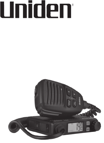
CMX660
PROFESSIONAL MOBILE CB RADIO
Owner’s Manual

CONTENTS
DESCRIPTION ...................................................... 5
WHAT’S IN THE BOX ........................................................... 7
CONTROLS AND CONNECTORS ......................................... 8
Radio (Front and Back) .....................................................8
Microphone .......................................................................9
INSTALLATION .................................................. 10
CONNECT POWER ............................................................ 10
Ground Information ......................................................11
Connect Power................................................................11
MARINE INSTALLATION .................................................. 12
CONNECT ANTENNA ......................................................... 12
Safety Notice ................................................................... 13
INSTALL MICROPHONE HANGER/
CONNECT MICROPHONE ............................................... 14
Install Microphone Hanger ............................................ 14
Connect Microphone ...................................................... 14
Disconnect the Microphone ..........................................15
INSTALL RADIO BRACKET/INSTALL RADIO ................... 15
Attach Side Rails ............................................................15
Attach Bracket/Install Radio .........................................16
EMERGENCY OPERATION ................................ 17
USING YOUR CMX660 ....................................... 17
LCD DISPLAY ..................................................................... 17
BASIC OPERATIONS .......................................................... 19
Turn On/O .....................................................................19
Transmit/Receive ............................................................ 20
Adjust Volume ................................................................20
Select Channel before Transmit/Receive .....................20
Adjust Squelch ................................................................ 21
Automatic Noise Limiter (ANL/HI-CUT) .........................21
Adjust Radio Sensitivity (LO/DX) ..................................22
CHANNEL SCAN................................................................. 23
WEATHER MODE WX MODE .......................................... 23
Set Weather Scan ............................................................ 24
Set Weather Alert Mode ................................................. 25
MENU OPERATION ............................................................ 25
Set Dimmer .....................................................................25
Set Key Beep ...................................................................26
Set Roger Beep ...............................................................27
Set Battery Check ...........................................................27
Set FLIP ............................................................................ 28
PREVENTIVE MAINTENANCE .......................... 28
MAINTENANCE ................................................. 28
TROUBLESHOOTING ........................................ 29
SERVICING YOUR RADIO ................................. 30
SPECIFICATIONS ............................................... 31
FCC PART 15 & IC COMPLIANCE ...................... 34
FCC PART 15 COMPLIANCE .............................................. 34
IC COMPLIANCE ................................................................ 34
ONEYEAR LIMITED WARRANTY .................... 35
RADIO CODE DEFINITIONS ............................. 39

5
DESCRIPTION
Your Uniden CMX660 represents the highest
quality communications device designed for use
in the Citizens Band Radio Service. It will operate
on any of the 40 AM frequencies authorized by the
Federal Communications Commission (FCC).
The CMX660 is designed to provide years of
trouble-free service. Its slim profile can fit easily
under the seat to free up space in the vehicle’s
cabin. Its rugged components and materials are
capable of withstanding harsh environments.
Please read this Owner’s Manual carefully to
ensure you gain the optimum performance of the
unit.
The Citizens Band Radio Service is under the
jurisdiction of the Federal Communications
Commission (FCC). Any adjustments
or alterations which would alter the
performance of the radio’s original FCC
type acceptance, or which would change the
frequency determining method, are strictly
prohibited.

6
Replacement or substitution of crystal,
transistors, ICs, regulator diodes, or any
other part of a unique nature, with parts
other than those recommend by Uniden,
may cause violations of the technical
regulations in Part 95 of the FCC Rules or in
violation of type acceptance requirements in
Part 2 of the rules.
This is an FCC rule and applies to all CB radio
operators.
FEATURES
• 40 AM Channels • 7 Weather Channels
• Channel Monitor (SQL 0) • Weather Channel Scan
• Emergency Channel 9/19 • Weather Alert
• Channel Scan • Volume Control
• Squelch Control • High Cut
• Automatic Noise Limiter • Roger Beep
• Key Beep • Backlight Dimmer Control
• S/RF Meter • Battery Check
• Inverting display
7
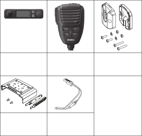
WHAT’S IN THE BOX
CMX660 Radio Microphone Microphone
Hanger with
Hardware
Not Shown:
Printed
Materials
CMX660 Slide
Mount Bracket
with Hardware
CMX660 DC
Power Cord
with Fuse
8
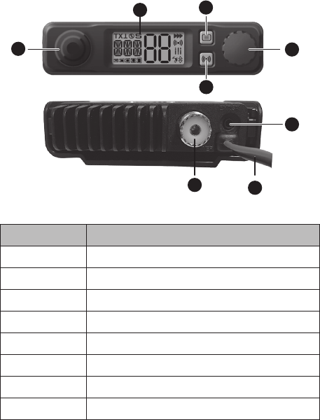
CONTROLS AND CONNECTORS
Radio (Front and Back)
1
87
FRONT
BACK
6
4
2
5
3
NUMBER NAME
1 MIC Jack
2 LCD
3 Menu
4 VOL/SQ, POWER knob
5 Local/DX
6 External Speaker Jack
7 Power Cables
8 Antenna Connection
9
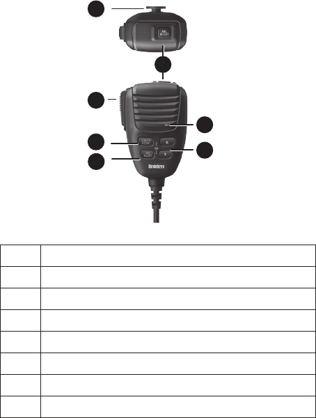
Microphone
1
2
3
4
5
6
7
NO. NAME
1 Microphone Hanger
2 ANL / HI-CUT
3 Push to Talk
4 CH9/19|SCAN
5 WX / ALERT
6 Channel UP and DOWN
7 Microphone

10
INSTALLATION
You can install the CMX660 either on top/
underneath a flat surface like a dashboard or
under the driver’s seat in a vehicle. Select a location
that is convenient for operating the radio but does not
interfere with the driver or passenger.
Plan the location of the radio and microphone
brackets before beginning installation.
Check the engine compartment and adjust
wiring that may interfere with bracket
installation.
The basic steps to install this unit are:
• Connect Power
• Connect Antenna
• Install Microphone Hanger/Connect
Microphone
• Install Radio Bracket/Install Radio
CONNECT POWER
Uniden recommends connecting the power lead
to the Ignition Switch Accessory Terminal. This
way, the radio is automatically turned off when the
ignition switch is turned off.
As an alternative, the power cord may be
connected to an available terminal on the fuse
block or to a point in the wiring harness. However,
be careful not to create a short circuit. If in doubt,
contact your vehicle dealer for information.
11
The CMX660 can operate on 12VDC power supply.
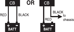
Ground Information
This radio may be installed and used in any 12-
volt DC negative ground system vehicle.
With a negative ground system, the negative (-)
battery terminal is usually connected to the vehicle
motor block.
Connect the red DC power cord from the radio to
the positive (+) battery terminal or other convenient
point. Then connect the black power cord to the
vehicle chassis or negative (-) battery terminal.
Connect Power
1. Connect the power cord to the power
connector from the radio.
2. Connect the red DC power cord to the
Ignition Switch Accessory Terminal or the
positive (+) battery terminal.
3. Next, connect the black power cord to the
Ignition Switch Accessory Terminal, the
vehicle chassis, or negative (-) battery
terminal.
12
4. Start the vehicle. The unit should turn on.
Turn the vehicle off. The unit should turn off.
MARINE INSTALLATION
Consult your dealer for information regarding
marine installation. It is important to adequately
ground the system and to prevent electrolysis
between the fittings in the hull and the water.
CONNECT ANTENNA
Because the maximum power output of the
transmitter is limited by the FCC, the quality of
your antenna is very important. To achieve the
maximum transmission distance, Uniden strongly
recommends that you install only a high quality
antenna. You have just purchased a superior radio;
don’t diminish its performance by installing an
inferior antenna.
Only a properly matched antenna system will
allow maximum power transfer from the 50-ohm
transmission line to the radiating element. Your
Uniden dealer is qualified to help you select the
proper antenna for your requirements. A whip style
antenna may be used for automobile installation.
CAUTION: Never operate your radio with no
antenna or with a damaged antenna cable.
This can damage the radio.
13
A short “loaded” whip antenna is easier to install
on an automobile, but its efficiency is less than
that of a full quarter-wave whip antenna.
Once your antenna is installed, tune it using a
Standing-Wave Ratio (SWR) meter (not included):
set it to channel 20 and adjust the antenna until
the SWR is as close as 1:1 as possible.
CAUTION: Make sure the SWR is less than 2:1
before using the radio. An SWR higher than
2:1 can damage the radio.
Safety Notice
The antenna used for this radio must be properly
installed and maintained and must provide a
separation distance of at least 24 inches (61 cm)
from all persons and must not be collocated or
operated in conjunction with any other antenna or
transmitter. Never transmit if any person is closer
than the specified distance to the antenna.
Note that Uniden does not specify or supply any
antenna with this radio. While a 0 dBi gain antenna
is normal for a typical installation, the above limit
applies to any antenna with up to 3 dBi gain.
14
INSTALL MICROPHONE HANGER/CONNECT
MICROPHONE
Install Microphone Hanger
1. Find a location to install the microphone
hanger. When you install the hanger, take
the same precautions as installing the radio
(see page 10). Adjust wiring if necessary.
2. Hang the microphone onto the hanger.
Connect Microphone
Mic Jack
1. Pull back the MIC jack rubber cover and
slide it back along the cord.
2. Insert the MIC jack into the radio’s MIC
socket until it clicks into place.
3. Gently tug on the cable to be sure the
connection is locked.
15
4. Slide the rubber cover down the cable and
cover the MIC jack to seal it from dust.
If you want to use the extension cable, connect
the cable to the radio and the MIC to the
other end of the extension cable.
Disconnect the Microphone
1. Pull back the MIC jack rubber cover and
slide it back along the cord.
2. Push down the MIC jack’s lock tab; tug
gently on the MIC cord until it disconnects.
If you are using the extension cable,
disconnect the cable from the radio and
the MIC from the other end of the extension
cable.
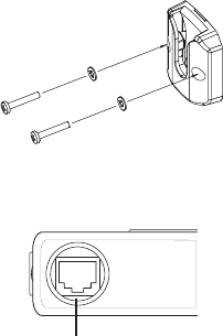
INSTALL RADIO BRACKET/INSTALL RADIO
The CMX660 uses a slide mount assembly to
mount the unit onto a surface. It can be mounted
either below or on top of a surface.
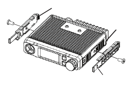
Attach Side Rails
1. Align the guide rails along the sides of
the radio and insert L-tabs into the L-tab
slots. Be sure the slide mount latches face
outward.
16
L-Tab
(2 on each rail)
L-Tab Slot
(2 on each side)
Slide Mount Latch
(1 on each rail)
2. Use the screws provided to fasten the guide
rails into position on the radio.
Attach Bracket/Install Radio
1. Using the screws provided, screw the
bracket into a stable, level surface. If
mounting the radio in a vehicle, for example,
screw the bracket onto the top of the
dashboard or underneath the dashboard.
Be sure the words “FRONT-SLIDE IN” are
visible from the front of the bracket.
Be sure you do not mount the bracket where
the screws can damage any wiring or
hardware. Move the wiring/hardware out of
the way or relocate the radio bracket.
2. Slide the back of the radio into the bracket
until the slide mounts latch and click into
place.
You can flip the display so that the indicators
appear right-side-up, no matter the
installation orientation (see “page 28).
17
EMERGENCY OPERATION
1. Press CH9/19|SCAN or use ▲ or ▼ to select
Channel 9.
2. Press PTT and speak clearly.
3. If there is no response, select an active
channel and ask that party to relay your
emergency broadcast on Channel 9.
All channels except Channel 9 may be used for
normal communication. The FCC reserves
Channel 9 for emergencies involving
the immediate safety of individuals or
protection of property. Use Channel 9 to
render assistance to a motorist.
This is an FCC rule and applies to all CB radio
operators.
USING YOUR CMX660
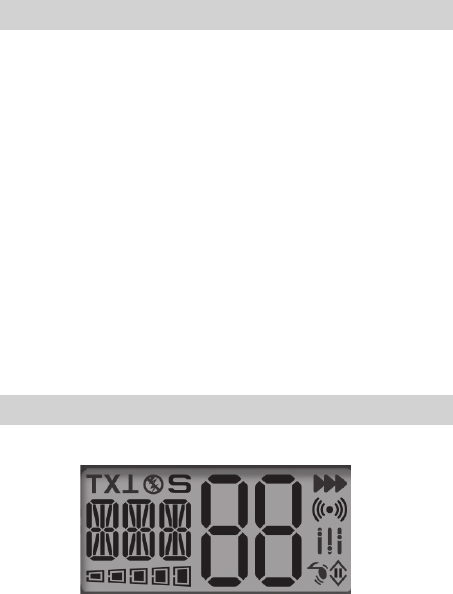
LCD DISPLAY
This LCD layout is for reference only. Different
icons display depending on scanner status.
Dimensions and layout may vary slightly.
18
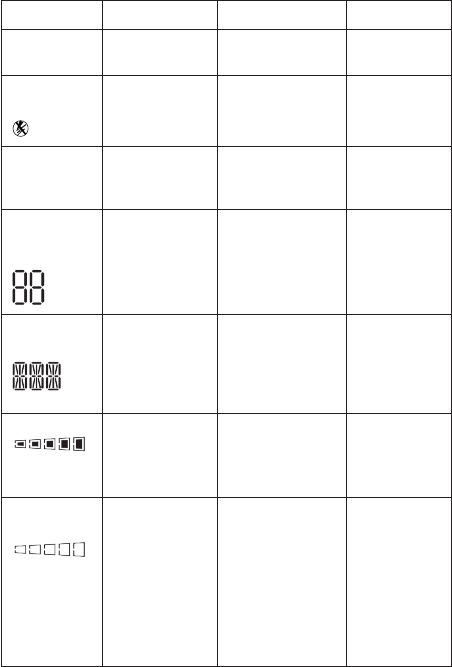
ITEM OFF ON BLINKING
TX
T
Receiving Transmitting
(see page 20)
Transmit
error
ANL Status
Indicator
• ANL off
• WX mode
is on.
• ANL on (see
page 22)
• CB mode is on.
NA
S
Channel Scan
is off.
Channel Scan
is on (see page
23)
NA
Channel,
Setting
Indicator
In Menus, FLIP
setting.
• In Menus, other
settings
• Channel
number
• Menu mode
on
• TX error
Mode
Indicator
CB or WX
Mode is on.
CB/WX, Menu,
Volume Setting,
SQ Setting,
Rotary Select
mode on.
FLIP setting
on.
TX Power • No CB signals
received.
• WX receive
is on.
Transmitting in
CB mode; icons
1-5 display (see
page 20).
NA
RX Signal
Strength
• No incoming
CB signals.
• WX mode
is on.
Receiving
signals in CB
or WX mode;
icons 1-5 display
according to
signal strength
(see page 20
for CB and page
24 for WX).
NA
19
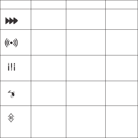
ITEM OFF ON BLINKING
WX Alert WX Alert is off. WX Alert is on
(see page 25).
NA
LO/DX • WX mode
is on.
• CB mode is on.
• LO/DX is on
(see page
22).
NA
Hi Cut • WX mode
is on.
• Hi Cut is off.
• Hi Cut is on
(see page
21).
• CB mode is on.
NA
Key Beep Key Beep
sound is off.
Key Beep sound
is on (see page
26).
Blinks during
ON/OFF
selection in
menus.
Roger Beep Roger Beep
sound is off.
WX mode is
on.
Roger Beep
sound is on (see
page 27).
• CB mode is on.
• WX mode is off.
Blinks during
ON/OFF
selection in
menus.
BASIC OPERATIONS
The CMX660 uses both the knob on the radio
and the ▲/▼ keys on the microphone to adjust
settings.
Turn On/O
The CMX660 remembers its power condition when
it is turned off or powered down. For example: if
the CMX660 is on when you disconnect power to
20
the unit, when you reconnect power it remembers
that it was on and returns to the ON state. You do
not have to press POWER again.
1. On the radio, press and hold the knob until
the LCD lights and the radio beeps. Power
is on.
2. Press and hold the knob again until the LCD
goes out and the radio beeps. Power is off.
Transmit/Receive
1. On the microphone, press and hold the PTT
key to transmit.
TX
and display.
2. Release PTT to receive.
TX
and go
away.
3. When receiving a transmission,
displays. The stronger the signal, the more
icons display (1 - 5).
Adjust Volume
Turn the knob on the radio to increase and
decrease the volume. There are 17 volume levels,
from 00 (Off) to 16.
VOL XX
displays.
Select Channel before Transmit/Receive
On the microphone, press the ▲/▼ keys to move
up or down the channels one at a time. Press and
hold them to move quickly through the channels.
The channel number changes (1 - 40).
21
If Key Beep is active, the microphone beeps
each time the channel changes.
Adjust Squelch
1. Press the knob on the radio until
SQL
displays.
2. Turn the konb to increase and decrease the
squelch level. There are 8 squelch levels,
from 0 to 7.
Set Squelch to 0 to have the radio monitor the
current channel for transmissions.
Automatic Noise Limiter (ANL/HI-CUT)
ANL (Automatic Noise Limiter) detects static
noise peaks and clips those peaks to preserve the
integrity of the received signal. HI-CUT (High Cut)
attenuates signals higher than a specific threshold.
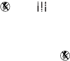
You can set either ANL or HI-CUT on individually,
or both of them on at the same time. If both are
turned on, both icons, and , display on the
LCD.
1. Press ANL/HI-CUT (on top of the
microphone) once. ANL on;
ANL
displays for
a moment on the LCD and the icon stays
on.
2. Press ANL/HI-CUT again; the icon goes away
and ANL is turned off
3. Press and hold ANL/HI-CUT (on top of the
microphone). HI-CUT is on;
HC
displays for a
22
moment on the LCD and the icon stays
on.
4. Press and hold ANL/HI-CUT again; the icon
goes away and HI-CUT is turned off
Adjust Radio Sensitivity (LO/DX)
Noise caused by strong signals from nearby
channels may be heard. The LO/DX settings
(LOCAL 1 and LOCAL 2) will reduce this noise by
reducing the radio’s sensitivity. If
L1
or
L2
do not
display, noise levels are not reduced.
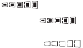
The number of bands on the LO/DX icon, ,
show which setting is active. Three bands ( )
indicate DX is active. Two bands ( ) indicate L1
is active. One band ( ) indicate L2 is active.
1. Press .
DX
displays for a moment and the
DX icon ( ) displays; noise levels are
reduced.
2. Press again.
L1
displays for a moment
and the L1 icon ( ) displays; noise levels
are reduced.
3. Press a third time.
L2
displays for a
moment and the L2 icon ( ) displays;
noise levels are reduced further.
4. Press again.
DX
displays for a moment
and the DX icon ( ) displays; noise levels
return to normal.
23
Occasionally, you may want to listen to
weaker signals (for example: receiving a
distant signal). In that case, do not reduce
sensitivity levels.
CHANNEL SCAN
When Channel Scan is on, the radio scans
channels until it receives a signal. It will move to
the next channel if no signal is received after 3
seconds.
1. Press and hold CH9/19|SCAN on the
microphone.
S
displays and the radio begins
scanning upward through the channels.
2. To exit Channel Scan mode, press
CH9/19|SCAN, PTT, or WX/ALERT.
WEATHER MODE WX MODE
Your radio combines a CB radio with a Weather
radio and a Weather Alert system. The Weather
Alert system sounds a seven-second signal in
the event of severe weather when you are in CB
mode. The Weather radio continually broadcasts
weather conditions when you are in Weather
mode.
1. Press WX/ALERT on the microphone. Your
radio is now in Weather radio mode.
WX XX
displays.

24
2. Press ▲ or ▼ to select weather channels 01
- 07. If you select a weather channel that is
broadcasting, displays.
Set Weather Scan
Weather Scan mode allows the radio to move to
the next weather channel if no signal is detected.
1. Press WX/ALERT on the microphone to enter
Weather mode.
WX XX
displays.
2. Press and hold CH9/19|SCAN to scan
weather channels.
S
displays.
3. To stop scanning weather channels and
return to Channel 9, press CH9/19|SCAN.
S
goes away.
To stop scanning weather channels and
return to the channel you started scanning
from, press and hold CH9/19|SCAN.
S
goes
away.
4. Press WX/ALERT to exit Weather mode.
If Weather Scan is ON when you turn off the
radio, Weather Scan remains ON.
Left at these setting (WX, WX Scan), you will
hear only weather broadcasts and Weather Alert
signals. To use your CB radio normally while
monitoring weather alerts, exit WX or WX Scan
modes.

25
Set Weather Alert Mode
Weather Alert mode only operates when you are
in CB mode; it does not operate in Weather mode.
In CB mode, the radio sounds an alert tone when
it detects a 1050Hz tone on a weather channel.
1. Press and hold WX/ALERT on the
microphone to turn Weather Alert on.
ALT
displays for a moment and displays.
2. Press and hold WX/ALERT to turn Weather
Alert off. The icon goes away.
MENU OPERATION
Press on the radio to access the 5 CMX660
menus.
Dimmer
Key Beep
Roger Beep
Battery Check
Flip
Press ▲ or ▼ on the microphone or turn the knob
on the radio to change the menu settings. Press
LO/DX to exit menus.
Menus will time out after about 10 seconds.
Set Dimmer
The Dimmer menu lets you dim the backlight or
make it brighter.

26
1. On the radio, press on the radio until
DIM
displays and the dimmer level displays and
blinks.
2. Turn the knob on the radio or press ▲ or
▼ on the microphone to scroll through the
options [oF (OFF), 1, 2, or 3].
3. When you have selected a dimmer level,
press again to move to the next menu
item and save the selection. A beep sounds.
Press LO/DX to exit menus or press any key
to cancel.
Set Key Beep
Key Beep sounds a beep tone when you press
a key. Select a Key Beep volume level to turn on
Key Beep.
1. On the radio, press until
BEP
,
the
icon,
and the beep volume level display.
2. Turn the knob on the radio or press ▲ or
▼ on the microphone to scroll through the
options [oF (OFF), 1 - 7].
3. When you have selected a Key Beep
volume level, press again to move to the
next menu item and save the selection. A
beep sounds. Press LO/DX to exit menus or
press any key to cancel.

27
Set Roger Beep
Turn Roger Beep on to transmit a Roger Beep
tone when you finish transmitting.
1. On the radio, press until
ROG
,
the
icon,
and the Roger Beep status display. Turn the
knob on the radio or press ▲ or ▼ on the
microphone to select on (
on
) or off (
oF
).
2. When you have turned the Roger Beep
function on or off, press again to move to
the next menu item and save the selection.
A beep sounds. Press LO/DX to exit menus
or press any key to cancel.
Set Battery Check
Turning Battery Check on lets the radio display
a notification (
BAT Lo
or
BAT HI
) if the battery power
supply is in the upper (high) or lower (low) range.
This notification displays for 2 seconds in 15
second intervals. A double beep also sounds.
1. On the radio, press until
BAT
displays.
The current Battery Check status also
displays and blinks.
2. Turn the knob on the radio or press ▲ or ▼
on the microphone to select on (
on
) or off
(
oF
).
3. When you have turned Battery Check on or
off, press again to move to the next menu
item and save the selection. A beep sounds.

28
Press LO/DX to exit menus or press any key
to cancel.
Set FLIP
Use FLIP to turn the LCD upside-down if you are
mounting the radio upside down.
1. On the radio, press until
FLP
displays and
blinks.
2. Turn the knob on the radio or press ▲ or ▼
on the microphone to flip the LCD.
3. Press again to exit the menus and save
the selection. A double beep sounds. Press
LO/DX to exit menus or press any key to
cancel.
PREVENTIVE MAINTENANCE
Every six months:
1. Check the SWR.
2. Be sure all electrical connections are tight.
3. Inspect antenna coaxial cable for wear or
breaks in shielding.
4. Be sure all screws and mounting hardware
are tight.
MAINTENANCE
The CMX660 is designed to give you years
of trouble-free service. There are no user-

29
serviceable parts inside. Except for the fuse in the
DC power cord, no maintenance is required.
To replace a blown fuse:
1. Press ends of the fuse holder together. Twist
to open. Carefully separate the two pieces.
2. Remove the fuse and inspect. If blown,
replace with the same type fuse.
Use only the fuse specified for your CMX660.
Failure to do so may void your warranty.
TROUBLESHOOTING
In the event of system malfunction, perform the
following procedures:
PROBLEM SUGGESTION
Unit does not
power up
Check power cord connections.
Check fuse.
Check vehicle electrical system.
No reception Check microphone connection.
Check volume and squelch.
Check antenna.
Check antenna connection.
Poor Reception Check volume and squelch.

30
PROBLEM SUGGESTION
No Transmission Check microphone connection.
Be sure radio is not set to
Weather channel or Weather
Scan. Turn off to return to CB
mode.
Battery power
check displays Lo
or HI.
Make sure your power wires
have a good connection.
Check your battery charge; it
needs to be fully charged. Lower
voltage will cause a failure.
Check your alternator.
If you do not get satisfactory results after
performing these checks, visit the Uniden website
(www.uniden.com) for troubleshooting and FAQ
information.
SERVICING YOUR RADIO
It is the user’s responsibility to see that this radio
is operating at all times in accordance with the
FCC Citizens Radio Service regulations. We highly
recommend that you consult a qualified radio/
telephone technician for servicing and aligning this
CB radio product.
When ordering parts, be sure to specify the
correct model number and serial number of
the unit.

31
SPECIFICATIONS
GENERAL
Channel: 40
Frequency Range: 26.965 ~ 27.405 MHz
Frequency Control: PLL Synthesizer
Antenna
Impedance:
50 ohms, unbalanced
Power Input: 13.8VDC
Current Drain
TX: AM Full Modulation: 1.5A
(max)
RX: At no signal: 400mA (max)
Operating
Temperature:
–22°F to 140°F
–30°C to 60°C
Accessories: DC Power Cord with Built-In
Fuse
Microphone
Microphone Hanger with
Screws
Mounting Bracket with
Screws
Owner’s Manual
Part 95 Subpart D (FCC Rules)
32
Size (W x D x H): 4 in. W x 0.97 in. H x 3.86 in. D
(without knobs and jacks)
(102 mm W x 24.6 mm H x
98.2 mm D)
Weight: 0.9 Pounds
Antenna
Connector
M-Type
TRANSMITTER UNIT NOMINAL
Output Power: Watts 4
Hum and Noise: dB 40
Frequency
Tolerance:
% ±0.002
Spurious Rejection: dBc -70
RECEIVER UNIT NOMINAL
Sensitivity at 10 dB
S/N
dBm –110
Maximum
Sensitivity
dBm –114
Squelch Sensitivity dBm
dBm
Step 1: –107
(MIN)
Step 7: –47
(MAX)
Signal Meter S-9: dBm –67
33
Audio Output
Power (max.):
Watts 3
Adjacent Channel
Rejection:
dB 60
Image Rejection: dB 70
External Speaker
Impedance:
ohms 8
WEATHER RADIO UNIT NOMINAL
Usable Sensitivity
for 12dB SINAD
dBm –112
Distortion (0.5W
output) @ 1KHz ±
3KHz DEV.
% 3
Maximum Audio
Output Power
W 3
Alert Sense dB –110
Alert Frequency Hz 1040 to 1060
Squelch Sensitivity
(Threshold)
dBm –110
Specifications shown are typical and subject to
change without notice.

34
FCC PART 15 & IC COMPLIANCE
FCC PART 15 COMPLIANCE
This device complies with Part 15 of the FCC
rules. Operation is subject to the following two
conditions: (1) This device may not cause harmful
interference, and (2) this device must accept any
interference received, including interference that
may cause undesired operation.
Changes or modifications not expressly approved
by the party responsible for compliance could void
your authority to operate the equipment.
Avis de conformité à la FCC : Ce dispositif a
été testé et s’avère conforme à l’article 15 des
règlements de la Commission fédérale des
communications (FCC). Ce dispositif est soumis
aux conditions suivantes: 1) Ce dispositif ne doit
pas causer d’interférences nuisibles et; 2) Il doit
pouvoir supporter les parasites qu’il reçoit, incluant
les parasites pouvant nuire à son fonctionnement.
Tout changement ou modification non approuvé
expressément par la partie responsable pourrait
annuler le droit à l’utilisateur de faire fonctionner
cet équipement.
IC COMPLIANCE
This device complies with Industry Canada
license-exempt RSS standard(s). Operation is

35
subject to the following two conditions: (1) this
device may not cause interference, and (2) this
device must accept any interference, including
interference that may cause undesired operation
of the device.
Changes or modifications not expressly approved
by the party responsible for compliance could void
your authority to operate the equipment.
Cet appareil est conforme aux normes RSS
exemptes de licences d’Industrie Canada. Son
fonctionnement est soumis aux deux conditions
suivantes : (1) cet appareil ne doit pas causer
d’interférences nuisibles et (2), il doit pouvoir
accepter les interférences, incluant celles pouvant
nuire à son fonctionnement normal.
Tout changement ou modification non approuvé
expressément par la partie responsable pourrait
annuler le droit à l’utilisateur de faire fonctionner
cet équipement.
ONEYEAR LIMITED WARRANTY
Important: Evidence of original purchase is
required for warranty service.
WARRANTOR: UNIDEN AMERICA
CORPORATION (“Uniden”)
ELEMENTS OF WARRANTY: Uniden warrants,
for one year, to the original retail owner, this
36
Uniden Product to be free from defects in
materials and craftsmanship with only the
limitations or exclusions set out below.
WARRANTY DURATION: This warranty to the
original user shall terminate and be of no further
effect one year after the date of original retail
sale. The warranty is invalid if the Product is (A)
damaged or not maintained as reasonable or
necessary, (B) modified, altered, or used as part
of any conversion kits, subassemblies, or any
configurations not sold by Uniden, (C) improperly
installed, (D) serviced or repaired by someone
other than an authorized Uniden service center for
a defect or malfunction covered by this warranty,
(E) used in any conjunction with equipment or
parts or as part of any system not manufactured
by Uniden, or (F) installed or programmed by
anyone other than as detailed by the owner’s
manual for this product.
STATEMENT OF REMEDY: In the event that
the product does not conform to this warranty
at any time while this warranty is in effect,
warrantor will either, at its option, repair or
replace the defective unit and return it to you
without charge for parts, service, or any other
cost (except shipping and handling) incurred by
warrantor or its representatives in connection
with the performance of this warranty. Warrantor,
37
at its option, may replace the unit with a new or
refurbished unit. THE LIMITED WARRANTY
SET FORTH ABOVE IS THE SOLE AND
ENTIRE WARRANTY PERTAINING TO THE
PRODUCT AND IS IN LIEU OF AND EXCLUDES
ALL OTHER WARRANTIES OF ANY NATURE
WHATSOEVER, WHETHER EXPRESS,
IMPLIED OR ARISING BY OPERATION OF
LAW, INCLUDING, BUT NOT LIMITED TO ANY
IMPLIED WARRANTIES OF MERCHANTABILITY
OR FITNESS FOR A PARTICULAR PURPOSE.
THIS WARRANTY DOES NOT COVER OR
PROVIDE FOR THE REIMBURSEMENT
OR PAYMENT OF INCIDENTAL OR
CONSEQUENTIAL DAMAGES.
Some states do not allow this exclusion or
limitation of incidental or consequential damages
so the above limitation or exclusion may not apply
to you.
LEGAL REMEDIES: This warranty gives you
specific legal rights, and you may also have other
rights which vary from state to state. This warranty
is void outside the United States of America.
PROCEDURE FOR OBTAINING
PERFORMANCE OF WARRANTY: If, after
following the instructions in the owner’s manual
you are certain that the Product is defective, pack
the Product carefully (preferably in its original
38
packaging). The Product should include all parts
and accessories originally packaged with the
Product. Include evidence of original purchase and
a note describing the defect that has caused you
to return it. The Product should be shipped freight
prepaid, by traceable means, to warrantor at:
Uniden America Service
C/O Saddle Creek
743 Henrietta Creek Rd., Suite 100
Roanoke, TX 76262

39
RADIO CODE DEFINITIONS
The following list contains common “10-Codes”
used by CB radio operators for faster
communication and better understanding.
CODE MEANING CODE MEANING
10-1 Received poorly 10-34 Trouble at this
station
10-2 Receiving well 10-35 Confidential
information
10-3 Stop
transmitting
10-36 Correct time is
10-4 OK, message
received
10-37 Wrecker needed
at
10-5 Relay message 10-38 Ambulance
needed at
10-6 Busy, stand by 10-39 Your message is
delivered
10-7 Out of service,
leaving air
10-41 Please turn to
channel
10-8 In service,
subject to call
10-42 Traffic accident
at
10-9 Repeat message 10-43 Traffic tie up at
10-10 Transmission
completed,
standing by
10-44 I have a message
for you

40
CODE MEANING CODE MEANING
10-11 Talking too
rapidly
10-45 All units within
range please
report
10-12 Visitors present 10-50 Break channel
10-13 Advise Weather/
Road conditions
10-60 What is next
message
number
10-16 Make pickup at 10-62 Unable to copy,
use phone
10-17 Urgent business 10-63 Net directed to
10-18 Anything for us? 10-64 Net clear
10-19 Nothing for you,
return to base
10-65 Awaiting your
next message/
assignment
10-20 My location is 10-67 All units comply
10-21 Call by
telephone
10-70 Fire at
10-22 Report in
person to
10-71 Proceed with
transmission in
sequence
10-23 Stand by 10-77 Negative
contact
10-24 Completed last
assignment
10-81 Reserve hotel
room for

41
CODE MEANING CODE MEANING
10-25 Can you contact 10-82 Reserve room
for
10-26 Disregard last
information
10-84 My telephone
number is
10-27 I am moving to
channel
10-85 My address is
10-28 Identify your
station
10-91 Talk closer to
microphone
10-29 Time is up for
contact
10-93 Check my
frequency on
this channel
10-30 Does not
conform to FCC
rules
10-94 Please give me a
long count
10-32 I will give you a
radio check
10-99 Mission
completed, all
units secure
10-33 EMERGENCY
TRAFFIC
10-
200
Police needed at