Uniden America UT601 2.4GHz Wireless Microphone User Manual UM525 Paper OM
Uniden America Corporation 2.4GHz Wireless Microphone UM525 Paper OM
UserManual.wiki
>
Uniden America
>
UT601 User Manual
users manual
Navigation menu
Upload a User Manual
Namespaces
Wiki Guide
HTML
PDF
Info
Views
User Manual
Discussion / Help
Navigation

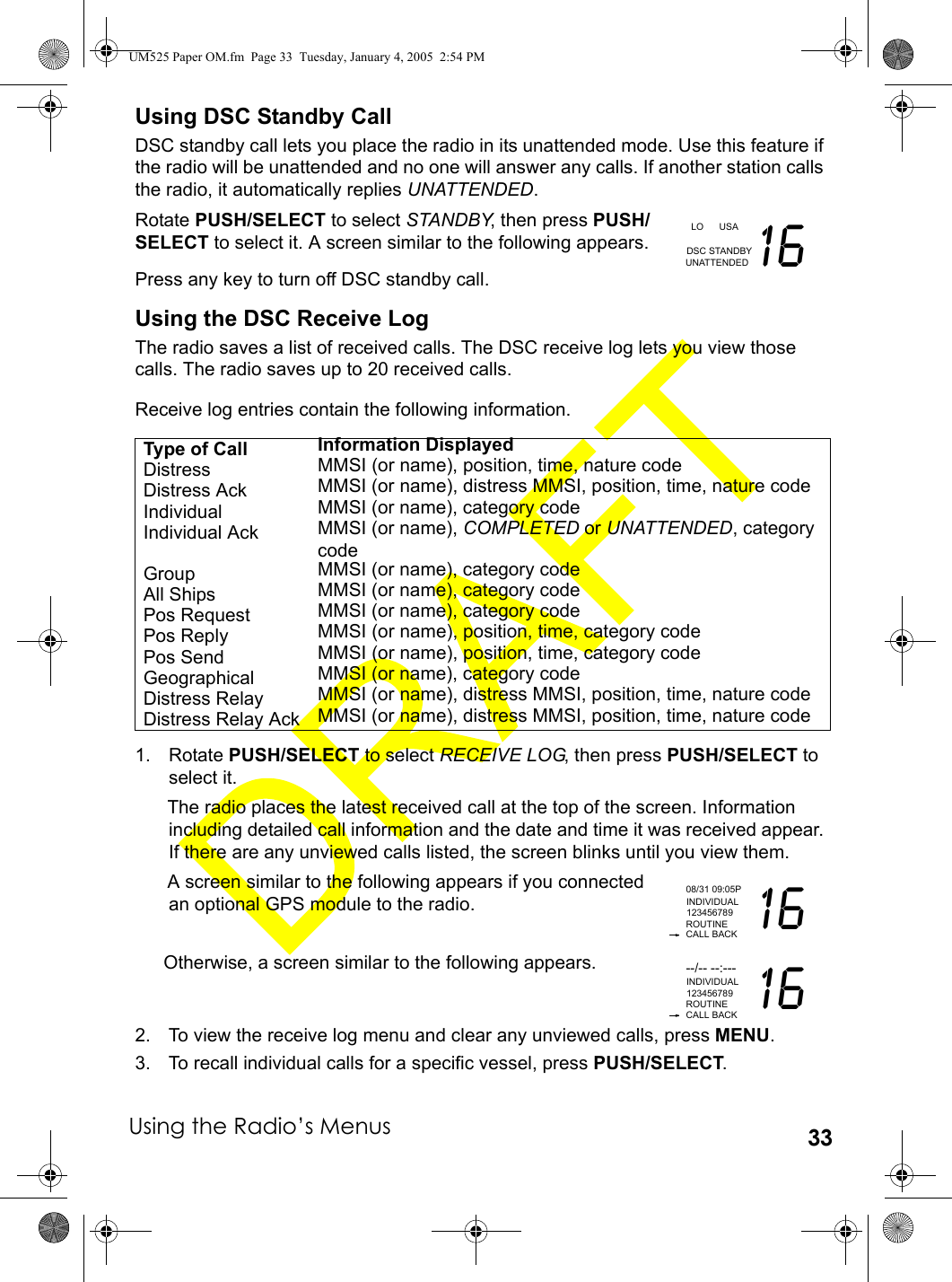
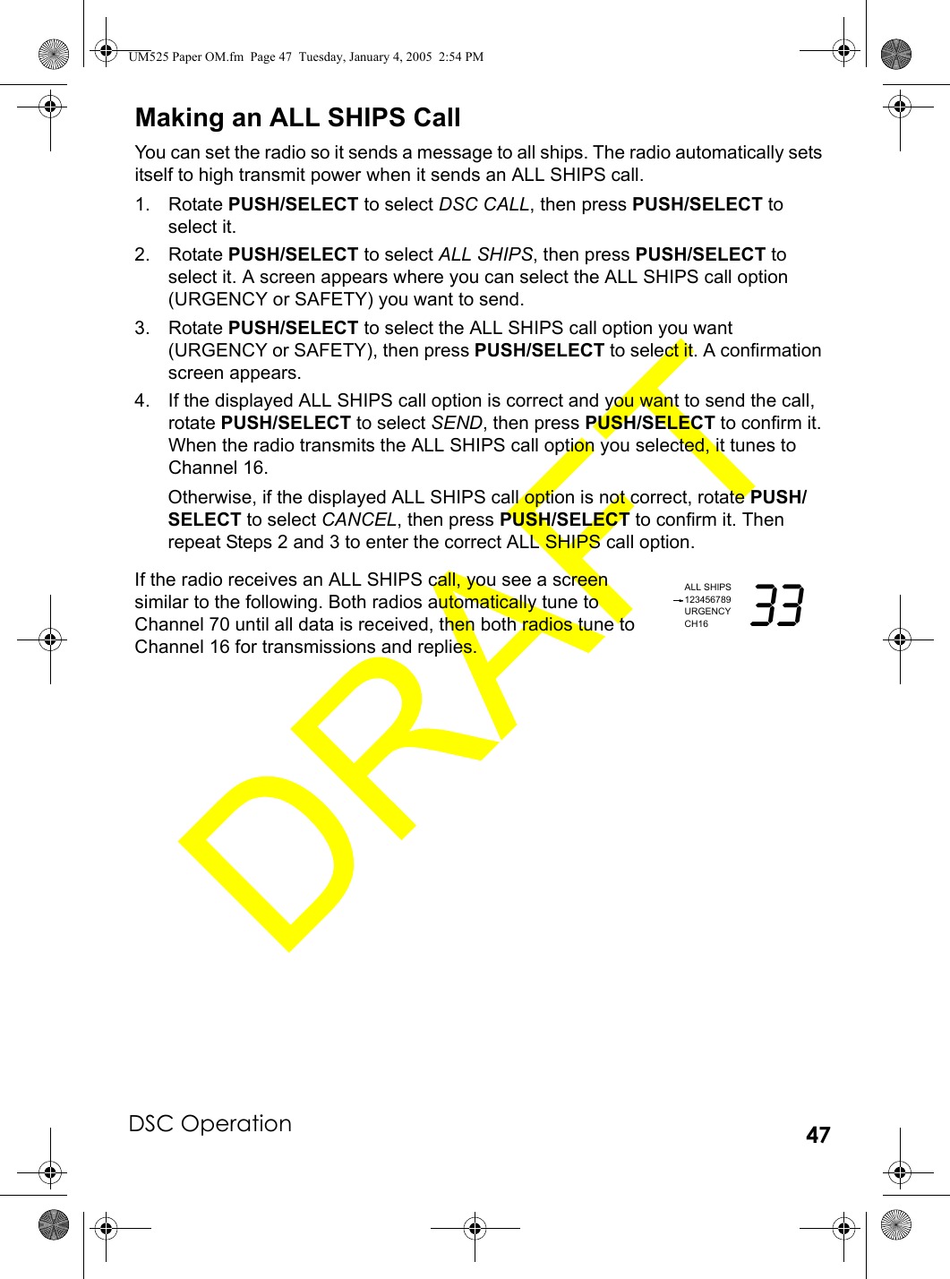
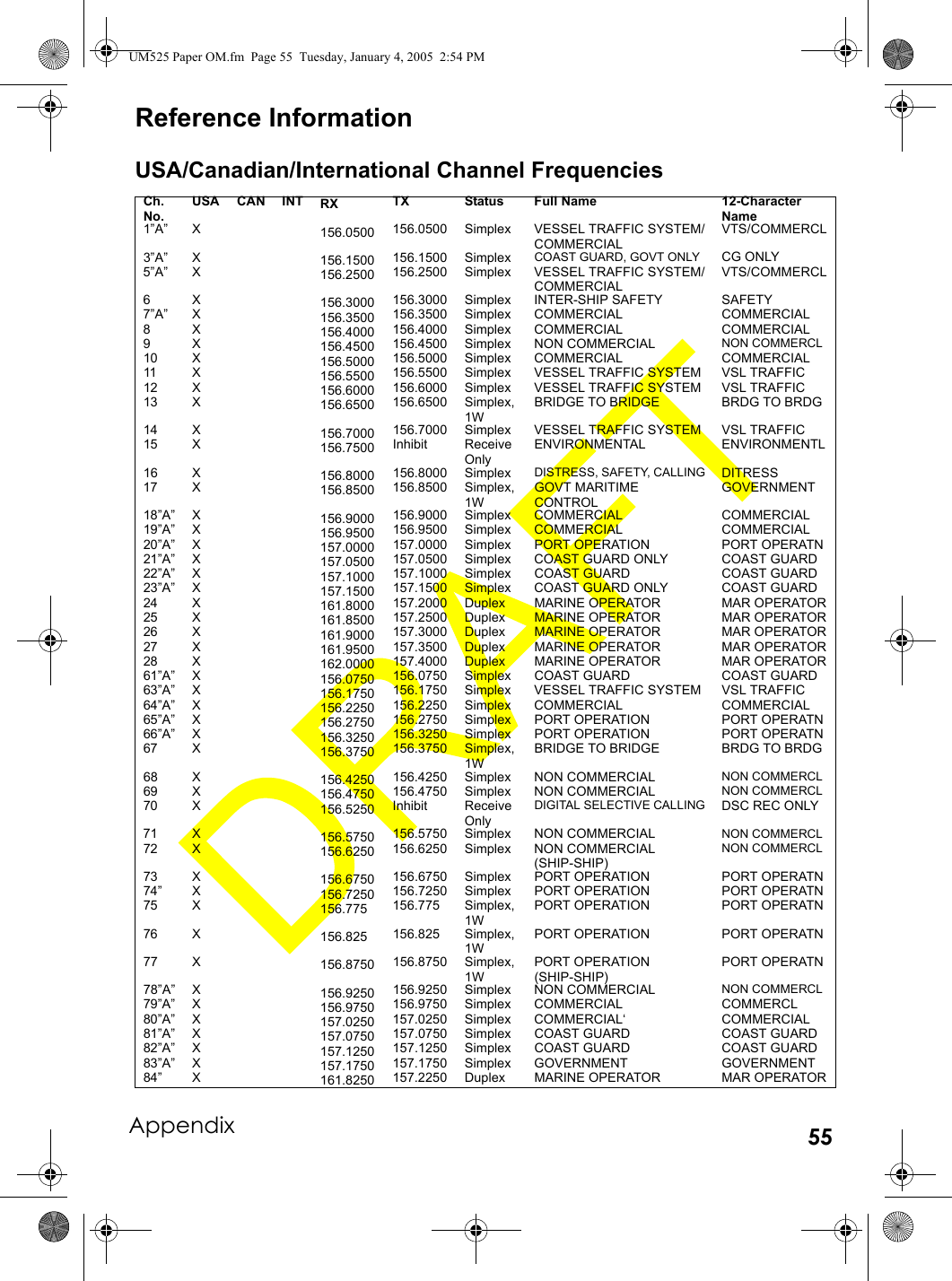
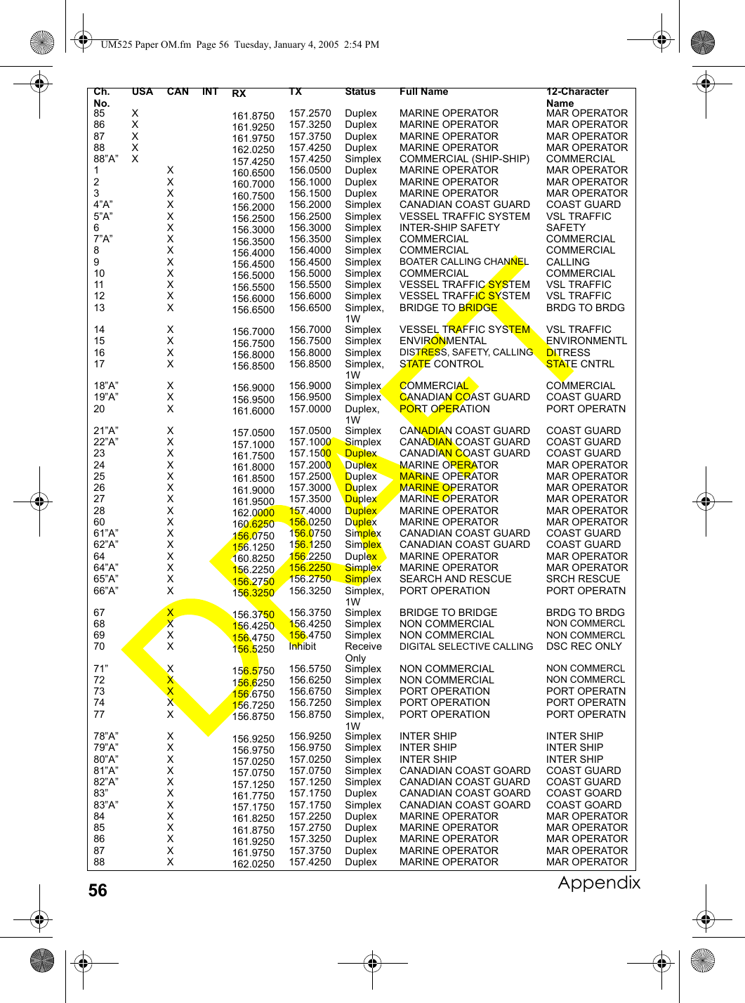
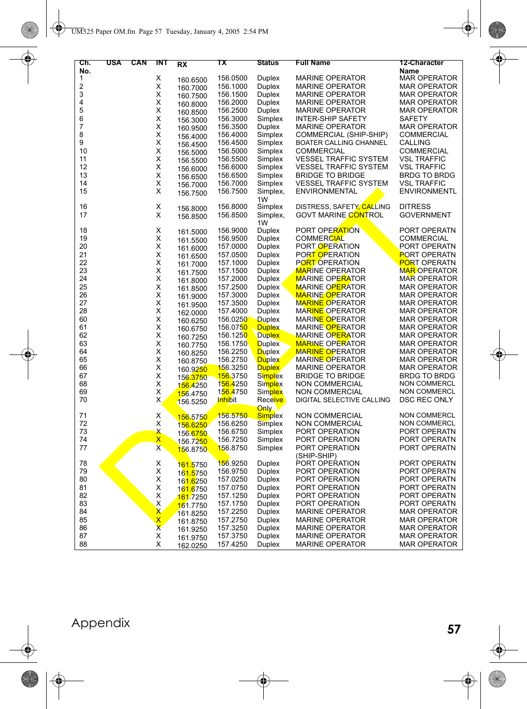
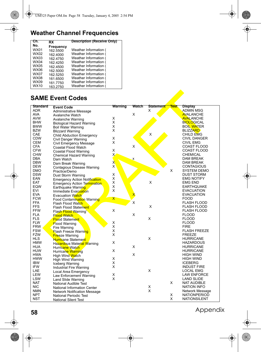
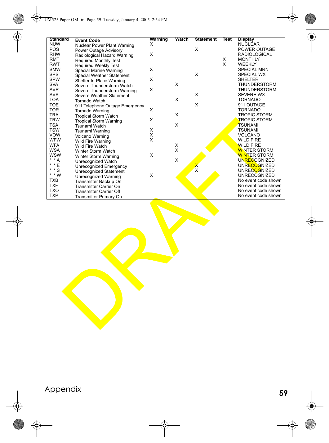
![DSC Operation46DSC OperationMaking a DSC Distress Call1. Lift the protective tab over DISTRESS then hold down DISTRESS for about 5 seconds. A screen appears where you can select a distress type.2. To send an undesignated distress call, press PUSH/SELECT to select it. Otherwise, to send a designated distress call, rotate PUSH/SELECT to select the distress type, then press PUSH/SELECT to select it. A confirmation screen appears.If the displayed distress call option is correct and you want to send the distress call, rotate PUSH/SELECT to select SEND, then press PUSH/SELECT to confirm it. Otherwise, if the displayed distress call option is not correct, rotate PUSH/SELECT to select CANCEL, then press PUSH/SELECT to confirm it. Then repeat Steps 1 and 2 to enter the correct distress call option.The radio checks Channel 70 before sending the distress call and displays the following screen. To cancel the distress call while this screen appears, press PUSH/SELECT.If the channel is busy, the radio waits until the channel clears, then it sends the distress call and sounds a distress tone. Then, the radio tunes to Channel 16 and Channel 70 and waits between 3 minutes and 30 seconds (210 seconds) and 4 minutes and 30 seconds (270 seconds) for an acknowledgement signal. The radio continues to sound the alarm and listen for an acknowledgement signal until it receives one.Receiving a DSC Distress CallIf the radio receives a DSC distress call, you see a screen similar to the following, and the radio sounds a distress tone. If the name of the vessel sending the distress call is programmed into the radio, the vessel’s name appears. Otherwise, the vessel’s MMSI, position, time, and nature code appear. Rotate PUSH/SELECT while a distress call is being received to display additional information about the distress call.If the sending radio does not send position and nature code information with its distress call, you see a screen similar to the following.DISTRESSUNDESIGNATED33FIREFLOODINGCOLLISIONGROUNDINGCAPSIZINGSINKINGADRIFTABANDONINGPIRACY/ARMEDOVERBOARD[EXIT]DISTRESS 33SENDCANCELBUSY 33CANCELWAITINGDISTRESS35°40.610N 33685749638139°46.564E08:24UFIREDISTRESSNO POSITION 33685749638FIREDSC OperationUM525 Paper OM.fm Page 46 Tuesday, January 4, 2005 2:54 PM](https://usermanual.wiki/Uniden-America/UT601/User-Guide-514930-Page-46.png)