Uniden America UT601 2.4GHz Wireless Microphone User Manual UM525 Paper OM
Uniden America Corporation 2.4GHz Wireless Microphone UM525 Paper OM
users manual
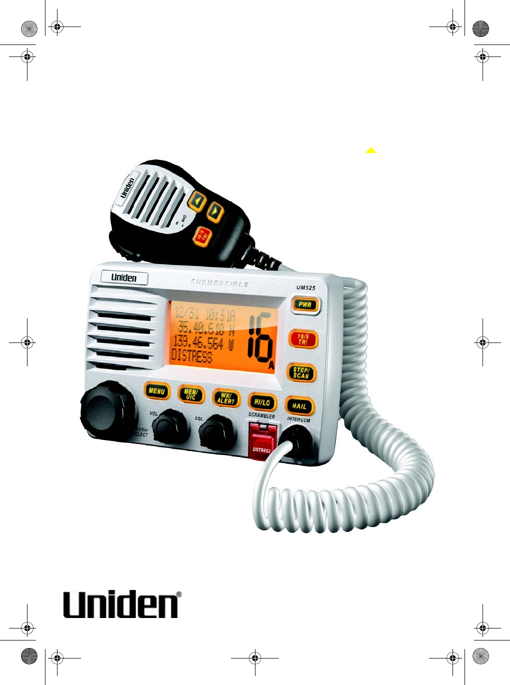
UM-525
MANUAL
OWNER’S
Marine Radio
Owner’s
Manual
UM525
Marine Radio
UM525 Paper OM.fm Page 1 Tuesday, January 4, 2005 2:54 PM

Maritime Radio Services Operation
2
Maritime Radio Services Operation
Warning! This transmitter will operate on channels/frequencies that have restricted
use in the United States. The channel assignments include frequencies assigned
for exclusive use of the U.S. Coast Guard, use in Canada, and use in international
waters. Operation on these frequencies without proper authorization is strictly
forbidden. For frequencies/channels that are currently for use in the U.S. without
an individual license, please contact the FCC Call Center at 1-888-CALL-FCC.
For individuals requiring a license, such as commercial users, you should obtain a
license application from your nearest FCC field office (for US users) or Industry
Canada (for Canadian users).
FCC / Industry Canada Information
Certification .................................................................... FCC Part 80 or RSS-182/188
Output Power ............................................................ 1 Watt (low) and 25 Watts (high)
Emission ....................................................................................... 16K0F3E, 16K0F2D
Transmitter Frequency Range ............................................... 156.025 to 157.425 MHz
FCC Identifier ........................................................................................... AMWUT601
IC Certification Number ............................................................................ 513C-UT601
This device complies with the GMDSS provisions with Part 80 of the FCC Rules, as
well as Part 15 of the FCC Rules. Operation is subject to the condition that this device
does not cause harmful interference.
Unauthorized changes or modifications to this equipment may void compliance with
the FCC Rules. Any change or modification must be approved in writing by Uniden
Corporation. Changes or modifications not approved by Uniden could void the user’s
authority to operate the equipment.
The cords on this product and/or accessories contain lead, a chemical known to the
State of California to cause birth defects or other reproductive harm. Wash hands after
handling. Uniden works to reduce lead content in our PVC coated cords in our
products and accessories.
Maritime Radio Services Operation
UM525 Paper OM.fm Page 2 Tuesday, January 4, 2005 2:54 PM

Contents 3
Contents
About Digital Selective Calling ............................................................................. 6
Introduction ............................................................................................................ 7
Feature Highlights ................................................................................................. 8
General Features ............................................................................................... 8
Weather Features ............................................................................................... 9
DSC Features ..................................................................................................... 9
Optional Features ............................................................................................... 9
Understanding Your Radio ..................................................................................11
About This Manual ........................................................................................... 11
How The Radio’s Controls Appear in This Manual ........................................... 11
Included With the Radio .......................................................................................13
Controls and Indicators .......................................................................................14
Front Panel ....................................................................................................... 14
Microphone ....................................................................................................... 14
Rear Panel Connectors .................................................................................... 14
Setting Up the Radio ............................................................................................15
Connecting the Antenna ................................................................................... 15
Connecting Power ............................................................................................ 15
Installation ........................................................................................................ 15
Choosing a Location ................................................................................... 16
Engine Noise Suppression .......................................................................... 16
Installing the Radio ...................................................................................... 17
Using a WHAM Microphone With the Radio .................................................... 17
A Look at the Radio .......................................................................................... 18
A Look at the Microphone ................................................................................ 19
A Look at the Display ....................................................................................... 19
Status Icons ................................................................................................. 19
Status Messages ..........................................................................................20
Basic Operation ....................................................................................................21
Turning the Radio On and Off .......................................................................... 21
Selecting a Channel ......................................................................................... 21
Transmitting and Receiving .............................................................................. 21
Adjusting the Transmit Power .......................................................................... 22
Using Scan ....................................................................................................... 22
Using Normal Scan ..................................................................................... 23
Using Triple Watch Scan ............................................................................. 23
Using Step ........................................................................................................ 23
Using Channel Mode ........................................................................................ 23
Using Hail ..........................................................................................................23
Contents
UM525 Paper OM.fm Page 3 Tuesday, January 4, 2005 2:54 PM

Contents
4
Using the Intercom .............................................................................................. 24
Using GPS .......................................................................................................... 25
Using Position Setting Mode ............................................................................... 25
Using Battery Hi/Lo Detect .................................................................................. 25
Using 16/9 TRI .................................................................................................... 26
Using Memory Channel ...................................................................................... 26
Saving Channels in Memory ...........................................................................26
Scanning Memory Channels ...........................................................................26
Using Triple Watch .............................................................................................. 26
Using the Radio’s Menus .......................................................................................28
Using the DSC Call Menu ................................................................................... 28
Using DSC Individual Call .............................................................................. 29
Using DSC Group Call ................................................................................... 30
Using DSC ALL SHIPS Call ........................................................................... 30
Using DSC Position Request Call .................................................................. 31
Using Position Send Call ............................................................................... 32
Using DSC Geographical Call ....................................................................... 32
Using DSC Distress Relay Call ...................................................................... 32
Using DSC Standby Call ................................................................................ 33
Using the DSC Receive Log .......................................................................... 33
Using the Fog Horn Menu ....................................................................................34
Selecting a Fog Horn Sound .......................................................................... 34
Setting the Fog Horn Frequency .................................................................... 35
Setting the Vessel Type ................................................................................. 35
Setting the Fog Horn Volume ........................................................................ 35
Using the WHAM Page Menu ..............................................................................36
Using the Setup Menu .........................................................................................36
Using the Directory ........................................................................................ 36
Using Channel Tag ........................................................................................ 37
Setting the Local Time ................................................................................... 38
Setting Daylight Saving Time ......................................................................... 38
Setting FIPS Codes ....................................................................................... 38
Disabling Auto Channel Switch ...................................................................... 40
Position Reply ................................................................................................ 40
Setting Up a WHAM ....................................................................................... 40
Setting Up a Group MMSI .............................................................................. 42
Setting Up a User MMSI ................................................................................ 42
Setting a Scrambler Code .............................................................................. 43
Using the System Menu .......................................................................................44
Adjusting the Contrast ....................................................................................44
Adjusting the Display and Key Brightness ......................................................44
Adjusting the Key Beep ..................................................................................44
Performing a Radio Self Test ..........................................................................45
UM525 Paper OM.fm Page 4 Tuesday, January 4, 2005 2:54 PM

Contents 5
DSC Operation ......................................................................................................46
Making a DSC Distress Call ............................................................................. 46
Receiving a DSC Distress Call ......................................................................... 46
Making an ALL SHIPS Call ...............................................................................47
Other Settings .......................................................................................................48
Using the Weather Function ............................................................................. 48
Using Weather Alert .................................................................................... 48
Using SAME Alert ....................................................................................... 48
Using the Scrambler ......................................................................................... 48
Care and Maintenance .........................................................................................50
Frequently Asked Questions ...............................................................................51
Specifications .......................................................................................................52
Appendix ...............................................................................................................54
NMEA Operation .............................................................................................. 54
NMEA Input ................................................................................................. 54
NMEA Output .............................................................................................. 54
Reference Information ...................................................................................... 55
USA/Canadian/International Channel Frequencies ..................................... 55
Weather Channel Frequencies ................................................................... 58
SAME Event Codes .................................................................................... 58
Initialization Settings ................................................................................... 60
Three Year Limited Warranty ...............................................................................61
UM525 Paper OM.fm Page 5 Tuesday, January 4, 2005 2:54 PM

About Digital Selective Calling
6
About Digital Selective Calling
The U.S. Coast Guard and other rescue authorities offer radiotelephone service to
mariners as part of the Global Maritime Distress and Safety System. This service,
known as Digital Selective Calling (DSC), lets mariners instantly send automatically
formatted distress alerts to rescue authorities anywhere in the world. Digital selective
calling also lets mariners initiate or receive distress, urgency, safety and routine
radiotelephone calls to or from any similarly equipped vessel or shore station, without
requiring either party to be near a radio loudspeaker. DSC acts like the dial and bell of
a telephone, allowing you to “direct dial” and “ring” other radios, or allow others to
“ring” you, without having to listen to a speaker.
Your radio's DSC Call feature lets you transmit and receive DSC Calls based on ITU-R
M.493-11. You can send a distress message in an emergency situation, send and
receive position data to and from other vessels, and set up and use a directory of
other vessels with DSC radios.
You can also use the radio's NMEA input and output feature to display and use vessel
information. DSC calls your radio can send and receive include distress, individual,
individual ack, ALL SHIPS, group, position request, position reply, and position send.
DSC calls your radio can receive include distress ack, geographic, distress relay, and
distress relay ack.
About Digital Selective Calling
UM525 Paper OM.fm Page 6 Tuesday, January 4, 2005 2:54 PM

Introduction 7
Introduction
Your Uniden UM-525 Marine Radio combines state-of-the-art technology with
rugged durability and ease of use. The radio's all solid-state design and
conservatively-rated components and materials make it an ideal choice for harsh
marine environments. The radio's large display and backlit control buttons make it
easy to use even in extreme lighting and weather conditions.
The radio's memory channel scan feature lets you set it so it quickly scans and tunes
only the channels you select. The Triple Watch feature lets you easily scan
emergency channels along with any channel you want, and you can tune emergency
channels by pressing a single button. The weather alert features let you monitor
weather alert broadcasts and even sound an audible alarm if bad weather is
reported in an area you specify.
You can connect an optional GPS module to the radio to help keep track of your
current location with space-age precision. You can connect and use a wide variety of
optional equipment with the radio, including an FMB321 flush mount, hailer horn,
GPS module, wireless microphones, and a plotter. You can connect and use WHAM
and WHAM x 4 wireless microphones with the radio, making onboard
communications as flexible as you need them to be. You can even install an optional
scrambler board in the radio and use the radio's scrambler feature, letting you
communicate privately with other vessels that have a scrambler installed.
You should read the rest of this Operating Guide thoroughly to acquaint yourself with
all of your radio's features and functions. Save your receipt as proof-of-purchase in
case you ever need to have warranty service on the radio. Features, specifications,
and availability of optional accessories are all subject to change without notice.
Note: Your radio meets the stringent JIS7 waterproof specification. This means that
the radio and microphone can be submerged to a depth of 1 meter for up to 30
minutes without incurring damage.
Introduction
UM525 Paper OM.fm Page 7 Tuesday, January 4, 2005 2:54 PM

Feature Highlights
8
Feature Highlights
General Features
Memory Channel Scan - You can set the radio so it scans only the channels you
select.
Triple Watch - The radio lets you scan Coast Guard/Distress/Hailing Channel 16,
secondary Coast Guard/Distress/Hailing Channel 9, and the currently selected
channel in order.
Memory Channel Step - You can set the radio so it quickly tunes channels saved in
the radio's memory.
One-Touch Emergency Channel - You can quickly tune the radio to Coast Guard/
Distress/Hailing Channel 16 and secondary Coast Guard/Distress/Hailing Channel 9
by pressing a single button.
Hi/Lo Transmit Power - You can set the radio's transmit power to 25 watts or 1 watt.
Channel Mode - You can set the radio's channel mode to USA, INT (international), or
CAN (Canada).
Contrast Adjustment - You can adjust the display's contrast to make it easier to see
in extreme conditions.
Display Backlight/Key Light Adjustment - You can adjust the brightness of the
display and the keys on the radio to make them easier to see in extreme conditions.
Key Beep Adjustment - You can adjust the volume of the tone you hear when you
press a key.
Self Test - The radio automatically tests its hardware and displays the test results.
Channel Tag - Lets you change the channel name that appears when you tune a
channel.
Auto Position Reply Disable - You can set the radio so when it receives a position
request call, it does not automatically reply with your current position.
Standby - You can set the radio to its unattended mode.
Receive Log - You can set the radio so it records a log of received calls. You can view
the receive log, making it easy to see when somebody calls your vessel.
Feature Highlights
UM525 Paper OM.fm Page 8 Tuesday, January 4, 2005 2:54 PM

Feature Highlights 9
Weather Features
WX Alert Decode Mode - You can set your radio to monitor a selected weather
radio channel for weather emergency signals or SAME (Specific Area Message
Encoding) alerts for areas you specify. This lets you receive the earliest possible
warning when bad weather is in the area or a national, regional, or local emergency
has been detected.
FIPS Code Programming - You can program your radio with up to 30 FIPS (Federal
Information Processing Standard) codes for the areas you desire. If the radio
receives a SAME alert tone, it checks it against the FIPS codes you programmed
and alerts you if it finds a match.
DSC Features
DSC Call - You can use the radio to transmit and receive DSC Call information.
See “Using the DSC Call Menu” on Page 28 for more information about DSC Call.
DSC Directory - You can set up a directory of other vessels that have a DSC-
capable radio with a Maritime Mobile Service Identity (MMSI) number.
Auto Channel Switch Disable - You can set the radio so it does not automatically
change the channel when it receives a DSC Call. The radio automatically sends a
signal to the calling vessel that shows that your vessel's radio is unattended, and
does not tune to the requested channel.
Optional Features
Scrambler - If you install an optional scrambler board in the radio, you can set the
radio so it scrambles your voice when you transmit, helping you avoid being
overheard by other vessels.
Hailer Features - You can use these features if you connect an optional hail horn to
the radio.
•Loud Hailer - You can use the radio to talk and listen using the speaker.
•Fog Horn - You can use the radio to sound a fog horn. If you connect a GPS
receiver to the radio, the radio can even sound the appropriate fog horn sound
based on its location and situation.
GPS Features - You can use these features if you connect an optional GPS receiver
to the radio.
•GPS Intuitive - The radio automatically suggests the correct channel mode
based on its current location (USA, International, and Canadian channels).
•Automatic Local Time Setting - The radio sets itself to the correct local time.
•Automatic Fog Horn - The radio sounds the appropriate fog horn sound based
on its location and situation.
UM525 Paper OM.fm Page 9 Tuesday, January 4, 2005 2:54 PM

Feature Highlights
10
•NMEA Input - The radio displays information such as your vessel's latitude and
longitude, speed and course, and the date and time. You can also send position
information and GPS Intuitive data using this feature.
•NMEA Output - The radio automatically passes received DSC information to an
optional connected chart plotter.
WHAM Input - If you connect an optional 900 MHz analog WHAM microphone to the
radio, you can use it to control the radio from almost anywhere aboard your vessel.
WHAM x 4 Input - If you connect an optional 2.4 GHz digital WHAM x 4 microphone
to the radio, you can use it to control the radio from almost anywhere aboard your
vessel, and each WHAM x 4 user can communicate with each other. You can also use
the radio's intercom function to communicate with each WHAM x 4 user. You can even
use a second base radio as an intercom.
UM525 Paper OM.fm Page 10 Tuesday, January 4, 2005 2:54 PM

Understanding Your Radio 11
Understanding Your Radio
About This Manual
The screen displays used in this manual are representations of what might appear
when you use your radio. Since what you see depends on the frequencies for your
area and the settings you select, you might notice some differences between what is
in this manual and what appears on your radio's display. Buttons you press appear
in bold type and text that appears on the display appears in italic type.
How The Radio’s Controls Appear in This Manual
To help navigate the radio's menus, the steps shown in this manual describe the
displays you see and the keys you press or control you operate to get a desired
result.
This example shows you how to use the radio's menu to program a user MMSI for
the first time. It shows you the control to use (PUSH/SELECT) to view a series of
choices and the correct option to select (USER MMSI) as you rotate PUSH/SELECT.
It also instructs you to press PUSH/SELECT to select the option.
Important: If you have already set the user MMSI, do not change it unless you
have received a new user MMSI. After you program a user MMSI for the first time,
you can only change it once more. If you try to change the user MMSI a third time,
the radio will not accept the change. To change the user MMSI again, you must
return the radio to Uniden for reprogramming.
1. Rotate PUSH/SELECT to select USER MMSI, then press
PUSH/SELECT to select it.
If a user MMSI has already n programmed, you see the
following screen. Stop here.
If a user MMSI has already been programmed twice, you
see the following screen. Stop here.
Otherwise, if a user MMSI has not been programmed, you
see the following screen.
AUTO CH SW
POS REPLY
WHAM
USER MMSI 16
USER MMSI
685749638 16
USER MMSI
685749638 16
CAN’T CHANGE
OVER 2 TIMES
USER MMSI
--------- 16
Understanding Your Radio
UM525 Paper OM.fm Page 11 Tuesday, January 4, 2005 2:54 PM

Understanding Your Radio
12
2. To enter the first digit of the user MMSI, rotate PUSH/SELECT until the digit
appears, then press PUSH/SELECT. The digit you entered appears and the flash-
ing cursor moves to the next position.
3. Repeat Step 2 for each of the user MMSI's digits. When you
have entered each of the user MMSI's digits, a confirmation
screen appears.
4. If the displayed user MMSI is correct, rotate PUSH/SELECT to select YES, then
press PUSH/SELECT to confirm it. The setup menu appears.
Otherwise, If the displayed user MMSI is not correct, rotate PUSH/SELECT to
select NO, then press PUSH/SELECT to confirm it. Then repeat Steps 2 and 3 to
enter the correct user MMSI.
If you are new to using a marine radio, be sure to read “About Digital Selective Calling”
on Page 6 for a quick background on DSC technology. The first thing you will need to
do is connect an antenna and power to the radio. Then you will need to install the
radio aboard your vessel. See “Connecting the Antenna” on Page 15, “Connecting
Power” on Page 15, and “Installation” on Page 15 if you need any help doing this.
USER MMSI
685749638 16
YES
NO
UM525 Paper OM.fm Page 12 Tuesday, January 4, 2005 2:54 PM

Included With the Radio 13
I
n
c
l
u
d
e
d
W
i
th the Radio
illustration - show radio, supplied mic, owners manual, and any other
items supplied with the radio in the gift box
Included With the Radio
UM525 Paper OM.fm Page 13 Tuesday, January 4, 2005 2:54 PM
Controls and Indicators
14
Controls and Indicators
Front Panel
(illus - show front panel, with callouts to controls)
Microphone
(illus - show microphone, with callouts to buttons)
Rear Panel Connectors
(illus - show rear panel, with callouts to controls and jacks)
illustration
Controls and Indicators
UM525 Paper OM.fm Page 14 Tuesday, January 4, 2005 2:54 PM

Setting Up the Radio 15
Setting Up the Radio
Connecting the Antenna
Your UM-525 has been designed to accommodate all of the popular marine VHF
antennas. However, the selection and the installation of the antenna is the
responsibility of the user or installer. A variety of antennas are available from a
number of quality suppliers. In general, we recommend an 8' antenna rated at 6dB
for powerboats, and a 4' antenna rated at 3dB for sailboats.
In general, you can increase your communication range by using a high-gain
antenna placed as high as possible above the water line. Locate the antenna away
from metal objects. Keep coax feed cables as short as practical.
The FCC has determined that excessive radiation poses a health risk to people near
radio transmitting antennas. Therefore, the antenna used with this radio should be
installed using the following guidelines to ensure a suitable distance between the
antenna and persons close by.
• Small whip antennas (3 dB) or smaller should be installed keeping at least 3 feet
separation distance between the radiating element and people.
• Larger antennas (6 dB or 9 dB) should be installed keeping at least a 6 feet sep-
aration distance.
• No person should touch the antenna or come closer than the separation dis-
tance when the radio is transmitting.
To connect the antenna to the radio, screw its connector onto the antenna jack on
the back of the radio.
Connecting Power
1. Connect the red wire of the supplied power cord to the positive (+) side of your
distribution circuit or battery.
2. Connect the black wire of the supplied power cord to the negative (-) side of your
distribution circuit or battery.
Note: The power cord is equipped with a fuse to protect the radio. Use only a six
(6) amp fast blow fuse for replacement.
3. Connect the power cord to the keyed connector on the power “pigtail”.
Installation
Caution: The UM-525 is designed to use a nominal 13.8 volt negative ground battery
system for power. Do not use a positive ground battery system to power the UM-525.
Setting Up the Radio
UM525 Paper OM.fm Page 15 Tuesday, January 4, 2005 2:54 PM

Setting Up the Radio
16
Keep in mind the flexibility designed into the UM-525 so that you can most
conveniently use it. Features which should be considered are:
• The universal mounting bracket may be installed on either the top or bottom of a
shelf, on a bulkhead, or for overhead mounting.
• The remote speaker wires can be used with an auxiliary speaker.
• All connections are “plug-in” type for easy removal of the radio.
• By using an optional WHAM or WHAM x 4 (Wireless Handheld Access
Microphone), the UM-525 can be mounted completely out of the way.
• Also optionally available is a flush mount bracket (FMB321).
Choosing a Location
Here are some important factors to consider in selecting the location for your UM-525.
• The UM-525 is completely waterproof, but will last longer if protected from spray
and splash.
• Keep the battery leads as short as possible. Direct connection to the battery is
most desirable. If direct connection can not be made with the supplied power lead,
any extension should be made with #12-14 AWG wire. Long extensions should
use larger gauge wire.
• Keep the antenna lead-in wire as short as possible. If you must use a long lead-in
wire as in the case of a sailboat masthead antenna installation, we recommend
you upgrade your lead-in wire according to the following table:
RG-58 <20'
RG-8X <35'
RG-8U <60'
• Locate your antenna as high as possible and clear from metal objects. The reli-
able range of coverage is a direct function of the antenna height.
• Select a location that allows free air flow around the heat sink on the rear of the
radio.
• Select a location well away from the ship's compass. Auxiliary speakers also
should be located away from the compass.
Engine Noise Suppression
Interference from the noise generated by the electrical systems of engines is
sometimes a problem with radios. The UM-525 has been designed to be essentially
impervious to ignition noise and alternator noise. However, in some installations it may
be necessary to take measures to further reduce the effect of noise interference. The
UM-525 radio DC battery wires, antenna lead, and accessory cables should be routed
away from the engine and engine compartment, and from power cabling carrying high
currents.
UM525 Paper OM.fm Page 16 Tuesday, January 4, 2005 2:54 PM

Setting Up the Radio 17
In severe cases of noise interference, it may be necessary to install a noise
suppression kit. Contact the dealer where you purchased the radio for more
information.
Installing the Radio
After you have carefully considered the various factors affecting your choice of
location, follow these steps to install the radio.
1. Position the radio (with the bracket, microphone, power cord, antenna and any
auxiliary cables installed) into the selected location to assure there is no
interference with the surrounding items.
2. Mark the location of the mounting bracket.
3. Remove the bracket from the radio and use it as a template to mark the holes to
be drilled for the mounting hardware.
4. Drill the holes and mount the bracket with hardware compatible with the material
of the mounting surface.
Note: Do not use mounting knobs other than the ones supplied. Do not insert the
knobs without attaching the bracket.
5. Connect all other auxiliary cables and accessories.
6. Install the radio in the mounting bracket and connect all cables and accessories
to the appropriate jacks and connectors.
Using a WHAM Microphone With the Radio
To connect a WHAM microphone to the radio, follow the steps listed in “Setting Up a
WHAM” on Page 40. Then refer to the owners manual provided with the WHAM
microphone for more information about connecting it to the radio.
UM525 Paper OM.fm Page 17 Tuesday, January 4, 2005 2:54 PM
Setting Up the Radio
18
A Look at the Radio
(illus - show controls on the front of the radio)
VOL - Rotate to adjust the volume.
SQL - Rotate to adjust the squelch.
PUSH/SELECT - Rotate to tune channels and highlight menu items you want to
select, then press to select the channel you tuned or the item you selected.
PWR - Press to turn the radio on or off.
16/9 TRI - Press once to quickly tune to EMG Channel 16. Press again to quickly tune
to EMG Channel 9. Press again to quickly tune to the previously-tuned channel. Hold
down for 2 seconds to set the radio to the Triple Watch mode (see “Using Triple
Watch” on Page 26).
STEP/SCAN - Repeatedly press to step through each channel in memory. Hold down
for 2 seconds to use the radio's channel scan feature (see “Scanning Memory Chan-
nels” on Page 26).
HAIL/INTERCOM - Press to turn on the hailer. Hold down for 2 seconds to use the
radio's intercom feature (see “Using the Intercom” on Page 24).
HI/LO/SCRAMBLER - Press to change the radio's output power. Hold down for 2
seconds to turn on the optional scrambler feature (see “Using the Scrambler” on
Page 48).
DISTRESS - Press to send a distress call (see “Making a DSC Distress Call” on
Page 46).
WX/ALERT - Press to listen to the active weather channel in your area. The currently-
tuned weather channel's channel number appears on the display. Hold down for 2
seconds to set the radio to the weather alert mode (see “Using the Weather Function”
on Page 48.
MEM/UIC - Press to add or delete the currently-tuned channel from the scan memory.
Hold down for 2 seconds to change the channel's mode (USA/CAN/INT).
MENU - Press to use the menu for the DSC Call, Fog Horn, System, and Setup
functions.
UM525 Paper OM.fm Page 18 Tuesday, January 4, 2005 2:54 PM

Setting Up the Radio 19
A Look at the Microphone
PTT - Press to send a transmission.
^/v - Repeatedly press to tune channels and highlight menu items you want to select.
16/9 TRI - Press once to quickly tune to EMG Channel 16. Press again to quickly
tune to EMG Channel 9. Press again to quickly tune to the previously-tuned channel.
A Look at the Display
Status Icons
TX - Appears while the radio is transmitting.
TRI - Appears while the radio is set to its Triple Watch mode.
LO - Appears while the transmit power is set to 1 watt.
HI - Appears while the transmit power is set to 25 watts.
USA - Appears while the radio is set to its USA channel mode.
INT - Appears while the radio is set to its international channel mode.
CAN - Appears while the radio is set to its Canada channel mode.
Note: The radio uses an optional GPS module connected to it to determine if it is set
to its USA, international, or Canada channel mode.
MEM - Appears when the currently-tuned channel is in the radio's memory.
WX - Appears while the radio is set to its WX mode.
ALERT - Appears while the radio is set to its WX Alert mode.
(illus - show a representation of the display with all status icons present)
UM525 Paper OM.fm Page 19 Tuesday, January 4, 2005 2:54 PM

Setting Up the Radio
20
Status Messages
Displayed messages appear on the third line of the display. The radio displays multiple
messages in turn for 5 seconds each.
GPS OK - Appears when a connected GPS module is working properly.
CHECK GPS - Appears when a connected GPS module is not working properly.
INPUT POS - Appears if the radio has not received valid GPS data for over 1 hour.
WHAM OK - Appears when a connected WHAM or WHAM x 4 microphone is working
properly.
Note: WHAM OK appears when an optional WHAM microphone is connected to the
radio, even if the WHAM microphone cannot communicate with the radio. WHAM OK
appears when at least one optional WHAM x 4 microphone is connected to the radio,
even if any WHAM x 4 microphone cannot communicate with the radio.
CHECK WHAM - Appears when a WHAM or WHAM x 4 microphone is not connected
to the radio or is not working properly.
SCRAMBLE ON - Appears when an installed scrambler board is working and the
scrambler is turned on.
USA AREA - Appears when the UIC is not set to USA mode, but the vessel is cur-
rently in a USA area.
INT AREA - Appears when the UIC is not set to INT mode, but the vessel is currently
in an INT area.
CAN AREA - Appears when the UIC is not set to CAN mode, but the vessel is cur-
rently in a CAN area.
AUTO FOG - Appears when the radio is set to its automatic fog horn feature.
MANUAL FOG - Appears when the radio is set to its manual fog horn feature.
UNDERWAY FOG - Appears when the radio is set to its under way fog horn feature.
STOP FOG - Appears when the radio is set to its stop fog horn feature.
SAIL FOG - Appears when the radio is set to its sail fog horn feature.
TOW FOG - Appears when the radio is set to its tow fog horn feature.
ANCHOR FOG - Appears when the radio is set to its anchor fog horn feature.
AGROUND FOG - Appears when the radio is set to its aground fog horn feature.
YELP FOG - Appears when the radio is set to its yelp fog horn feature.
BATTERY LOW - Appears when the battery connected to the radio is low.
BATTERY HIGH - Appears when the battery connected to the radio is high.
UM525 Paper OM.fm Page 20 Tuesday, January 4, 2005 2:54 PM

Basic Operation 21
Basic Operation
Turning the Radio On and Off
Press PWR to turn on the radio. The radio sounds a tone and USER MMSI and a
user MMSI number appear (if you have already set a user MMSI) or NO USER
MMSI appears (if you have not set a user MMSI).
Notes:
• If the radio is set to EMG (emergency) mode or WX (weather) mode, it
automatically tunes to the last channel you selected when you turn it on. Other-
wise, if the radio is in Scan mode, it tunes to the first channel in the scan list.
• If the radio is turned on for at least 3 seconds, it remembers the last channel you
tuned when you turn it off. Then, it tunes to that channel when you turn it back on.
• If you hold down MENU while turning on the radio, the Contrast level screen
appears. You can use this screen to set the contrast (see “Adjusting the Con-
trast” on Page 44).
Press PWR again to turn off the radio.
Selecting a Channel
Rotate PUSH/SELECT to select a channel. Rotating PUSH/SELECT clockwise
tunes forward through the channels, while rotating PUSH/SELECT counterclockwise
tunes backward through the channels. The channel indicator shows the currently-
tuned channel.
If the radio is set to MRN (marine) mode, channel numbers appear as two digits. If
the radio is set to WX mode, channel numbers appear as one digit.
Notes:
•If A appears next to a channel number, this indicates the channel is in the
simplex mode on the ship station transmit side of an international duplex
channel.
• You cannot use PUSH/SELECT to select Channel 70. Channel 70 is used only
in DSC mode.
Transmitting and Receiving
To transmit, hold down PTT on the microphone. TX appears. Release PTT to
receive. TX disappears.
Notes:
• If the radio is set to transmit at low power, you can change to high power by
pressing HI/LO/SCRAMBLER while transmitting.
Basic Operation
UM525 Paper OM.fm Page 21 Tuesday, January 4, 2005 2:54 PM

Basic Operation
22
• If you transmit continuously for longer than 5 minutes, TX and the channel number
blink and the radio stops transmitting. This warns you that the PTT button might
be stuck. To resume transmitting, release the PTT button then press it again.
• The radio cannot transmit on Channel 15 (USA).
• If you hold down PTT while turning on the radio, the radio sounds an error tone
and TX and the channel number blink. No key except HI/LO/SCRAMBLER works.
• You cannot transmit while the radio is set to WX mode, Scan mode, or Triple
Watch mode. If you press PTT while the radio is set to Scan mode or Triple Watch
mode, the radio cancels that mode but does not transmit.
• The radio cannot transmit voice data on Channel 70. Only DSC data such as
Distress Call can be transmitted on Channel 70.
Adjusting the Transmit Power
Repeatedly press HI/LO/SCRAMBLER to adjust the transmit power. If the transmit
power on the currently tuned channel is set to Hi (25W), pressing HI/LO/
SCRAMBLER changes it to Lo (1W), and LO appears. If the transmit power on the
currently tuned channel is set to Lo, pressing HI/LO/SCRAMBLER changes it to Hi,
and HI appears.
Important: The radio automatically sets itself to low transmit power if you tune to
Channels 13, 67, 75, or 76. Although you cannot change the transmit power to
high on Channel 75 or Channel 76, you can change the transmit power to high on
Channel 13 or Channel 67 by holding down Hi/Lo/SCRAMBLER while transmitting
on those channels.
Notes:
• You cannot change the transmit power if the radio is set to Scan mode.
• The radio automatically sets itself to high transmit power if you use PUSH/SELECT
to tune to Channel 16, press 16/9 TRI, or it receives a distress call. The radio sets
itself back to low power if you use PUSH/SELECT to select another channel.
Using Scan
The radio has two scan options available; normal scan and Triple Watch scan. Normal
scan lets you quickly scan and tune only those channels you select. Triple Watch lets
you easily scan emergency channels along with a channel you select.
Note: If you hold down STEP/SCAN while the radio is set to WX mode or EMG mode,
it cancels that mode and starts memory channel scanning.
UM525 Paper OM.fm Page 22 Tuesday, January 4, 2005 2:54 PM

Basic Operation 23
Using Normal Scan
To use normal scan, hold down 16/9 TRI for about 2 seconds if the radio is set to
Triple Watch (see “Using Triple Watch” on Page 26). The radio scans any channels
you saved to its memory and SCANNING appears.
Notes:
• If you use normal scan, the radio does not scan any emergency channels. Use
Triple Watch (see “Using Triple Watch” on Page 26) to scan emergency chan-
nels.
• You must save at least one channel in the radio's memory to use normal scan.
See “Saving Channels in Memory” on Page 26 for more information.
Using Triple Watch Scan
To use Triple Watch scan, hold down STEP/SCAN for about 2 seconds. The radio scans
emergency Channel 16, Channel 9, and the current memory channel. TRI appears.
Note: You must save at least one channel in the radio's memory to use Triple Watch
scan. See “Saving Channels in Memory” on Page 26 for more information.
Using Step
Step lets you quickly tune through the channels you saved in the radio's memory.To
use step, repeatedly press STEP/SCAN. The radio tunes a channel you stored in
the memory each time you press STEP/SCAN.
Using Channel Mode
Repeatedly press MEM/UIC to change the radio mode from USA to INTERNATIONAL
to CANADIAN. USA, INT, or CAN appears on the display. The radio saves the current
channel mode setting when you turn it off then turn it back on.
Note: Scan mode, WX mode, and EMG mode are cancelled when you press MEM/UIC.
Using Hail
Notes:
• You must connect an optional hailer horn to the radio to use the hail feature.
• If the radio receives a DSC call while the radio is set to the hail mode, informa-
tion about the call appears on the display for about 5 seconds.
To use the hail feature, press HAIL/INTERCOM then press PTT on the microphone
to speak. HA and TALK appear. Release PTT to listen. LISTEN appears and you
hear any response to your hail through the radio's speaker. To adjust the hail
volume, repeatedly press + and - on the microphone or rotate PUSH/SELECT on the
radio. To exit hail, press HAIL/INTERCOM again.
UM525 Paper OM.fm Page 23 Tuesday, January 4, 2005 2:54 PM

Basic Operation
24
Using the Intercom
The intercom feature lets you call optional WHAM x 4 microphones connected to the
radio. You can select and call one microphone, a group of microphones, or each
microphone connected to the radio.
Notes:
• WHAM x 4 microphone users can also call each other and the radio.
• WHAM x 4 microphone users cannot receive MRN signals received by the radio.
• If the radio receives a DSC call while the radio is set to the intercom mode, infor-
mation about the call appears on the display for about 5 seconds.
• If any WHAM x 4 microphone user cannot connect with the radio, intercom does
not work and the radio sounds an error tone.
• Intercom mode is cancelled if 16/9 TRI or DISTRESS is pressed.
Follow these steps to use the intercom.
1. Hold down HAIL/INTERCOM.
2. Follow one of these steps to select the WHAM x 4 microphone or microphones
you want to talk to.
a. To select one WHAM x 4 microphone, rotate PUSH/SELECT until the WHAM x
4 microphone you want to talk to is highlighted, then press PUSH/SELECT to
select it.
b. To select a group of WHAM x 4 microphones, rotate PUSH/SELECT until
GROUP is highlighted, then press PUSH/SELECT to select it. A screen appears
you can use to select the WHAM x 4 microphones you want to talk to. For each
WHAM x 4 microphone you want to talk to, rotate PUSH/SELECT to select it, then
press PUSH/SELECT.
Note: Only those WHAM x 4 microphones or sub radios with which the radio can
communicate appear on the display.
c. To select all connected WHAM x 4 microphones, rotate PUSH/SELECT until
ALL is highlighted, then press PUSH/SELECT to select it.
3. Press PTT on the microphone to speak. INTERCOM, the name of the WHAM x 4
microphone or microphones you selected, and TALK appear. Release PTT to lis-
ten. LISTEN appears and you hear any response from the WHAM x 4 microphone
or microphones you selected through the radio's speaker.
4. To exit intercom, press HAIL/INTERCOM again.
UM525 Paper OM.fm Page 24 Tuesday, January 4, 2005 2:54 PM

Basic Operation 25
Using GPS
Your radio can display GPS information if you connect an optional GPS module to it.
If the GPS module is properly connected to the radio and is working, GPS OK
appears on the radio's display. Otherwise, CHECK GPS appears.
Press PUSH/SELECT to display the current GPS mode, date, time, speed, course,
latitude, and longitude. Press PUSH/SELECT again to set the radio to its marine
mode.
Notes:
• You cannot set the radio to its GPS mode until it receives valid GPS data at least
once.
• If the radio is not receiving valid data from the connected GPS module, the GPS
data that appears blinks.
• If you press any key except DISTRESS, HAIL/INTERCOM or MENU, the radio
sets itself to its MRN mode. If you do not press any key, the radio sets itself to
GPS mode.
Using Position Setting Mode
To set the radio to its position setting mode, hold down PUSH/SELECT for about 2
seconds or press PUSH/SELECT when the radio is set to its MRN mode and does
not have a GPS module connected. A screen appears that you can use to set the
UTC time, latitude, and longitude used with DSC call.
To save the UTC time, latitude, and longitude you set, hold down PUSH/SELECT for
about 2 seconds.
Notes:
• When you set the time in position setting mode, be sure to set it to the current
UTC time, not local time.
• If the radio doesn't receive valid GPS data at least once, you cannot set it to
position setting mode.
• If the radio does not receive valid GPS data, it sounds a tone and INPUT POS
appears.
• The radio automatically alerts you if the UIC is currently set to a location but the
vessel is actually in another area's territorial waters. For example, the radio
alerts you if the UIC is set to USA but the vessel is actually in Canadian waters.
Using Battery Hi/Lo Detect
The radio alerts you if the connected battery is providing too much or not enough
power. If the battery is providing more than 16 volts, BATTERY HIGH appears. If the
battery is providing less than 11 volts, BATTERY LOW appears.
UM525 Paper OM.fm Page 25 Tuesday, January 4, 2005 2:54 PM

Basic Operation
26
Using 16/9 TRI
Press 16/9 TRI once to quickly tune the radio to Channel 16. Press 16/9 TRI again to
quickly tune the radio to Channel 9. Press 16/9 TRI a third time to quickly tune the
radio to the channel you tuned before you pressed 16/9 TRI.
Notes:
• Pressing 16/9 TRI cancels WX mode if the radio is set to WX mode.
• Pressing 16/9 TRI stops the radio from scanning if the radio is set to Scan mode.
• Pressing 16/9 TRI cancels Scan mode if the radio is set to EMG mode.
• The radio cancels EMG mode if you press WX, hold down Hi/Lo/SCAN, or rotate
PUSH/SELECT.
Using Memory Channel
Saving Channels in Memory
You can save channels you tune in USA, CAN, or INT mode into the radio's memory.
This makes it easy to quickly tune the channels again. To save a channel, tune the
channel then hold down SCAN/MEM for 2 seconds to save it. MEM appears. To delete
a channel from memory, tune the channel you want to delete then hold down SCAN/
MEM for 2 seconds. MEM disappears.
Notes:
• You cannot save a memory channel in WX mode.
• You must store more than one channel in the memory for memory channel scan to
work.
Scanning Memory Channels
You can scan channels you saved in the radio's memory. This lets you quickly access
and tune them. To scan memory channels, repeatedly press SCAN/MEM. Each
channel you saved appears each time you press SCAN/MEM.
Using Triple Watch
Triple Watch scans Channel 9 and Channel 16 every 2 seconds. If the radio detects a
transmission on Channel 9 or Channel 16 while set to Triple Watch, the channel
indicator blinks.
Hold down 16/9 TRI for about 2 seconds to turn Triple Watch on or off. If Triple Watch
is off, TRI appears and Triple Watch is turned on. If Triple Watch is on, TRI disappears
and Triple Watch is turned off.
UM525 Paper OM.fm Page 26 Tuesday, January 4, 2005 2:54 PM

Basic Operation 27
Notes:
• If Channel 9 is busy, the radio scans EMG Channel 9 and EMG Channel 16 in
turn.
• If you turn on Triple Watch and Channel 16 is busy, the radio receives EMG
Channel 16.
• If you turn on Triple Watch while the radio is set to EMG mode, the radio scans
EMG Channel 16, EMG Channel 9, and the last MRN channel (Channel 16 or
Channel 9).
• If you turn on Triple Watch while the radio is set to WX mode, the radio scans
EMG Channel 16, EMG Channel 9, and the WX channel.
• Triple Watch resumes if the signal of the channel you tuned is lost for 3 seconds.
• If the radio is scanning EMG Channel 9 or EMG Channel 16, only the CH
indicator changes. The channel tag display does not change.
UM525 Paper OM.fm Page 27 Tuesday, January 4, 2005 2:54 PM

Using the Radio’s Menus
28
Using the Radio’s Menus
To use the radio's menus, press MENU. A screen appears containing options you can
select to work with the radio's features.
To select an option, rotate PUSH/SELECT to highlight the option you want, then press
PUSH/SELECT to select it. In most cases, one or more additional pages of options
appear on the display. To return to the previous menu, press MENU. To exit, select
EXIT or hold down MENU for 2 seconds.
•DSC CALL - Lets you select and work with DSC Call options. See “Using the DSC
Call Menu”.
•FOG HORN - Lets you select and work with fog horn options. See “Using the Fog
Horn Menu” on Page 34.
•WHAM PAGE - Lets you select and work with WHAM page options. See “Using
the WHAM Page Menu” on Page 36.
•SYSTEM - Lets you select and work with system options. See “Using the System
Menu” on Page 44.
•SETUP - Lets you select and work with setup options. See “Using the Setup
Menu” on Page 36.
•EXIT - Exits the menu.
Using the DSC Call Menu
The radio's DSC Call feature lets you transmit and receive DSC Calls based on ITU-R
M.493-11. The radio supports the following DSC calls.
To select the DSC Call menu, rotate PUSH/SELECT to select DSC CALL, then press
PUSH/SELECT to select it.
Call Receive Transmit
Distress Yes Yes
Distress Ack Yes No
Individual Yes Yes
Individual Ack Yes Yes
ALL SHIPS Yes Yes
Group Yes Yes
Position Request Yes Yes
Position Reply Yes Yes
Position Send Yes Yes
Geographic Yes No
Distress Relay Yes No
Distress Relay Ack Yes No
Using the Radio’s Menus
UM525 Paper OM.fm Page 28 Tuesday, January 4, 2005 2:54 PM

Using the Radio’s Menus 29
Using DSC Individual Call
DSC individual call lets you transmit DSC Calls to an individual station. You can also
receive DSC calls from other stations.
1. Rotate PUSH/SELECT to select INDIVIDUAL, then press PUSH/SELECT to
select it. A screen showing the stations saved in the directory appears.
2. Follow one of these steps to select the station where you want to send a DSC call.
a. To select a station by vessel name, rotate PUSH/SELECT until the name of the
station you want to talk to is highlighted, then press PUSH/SELECT to select it.
b. To select a station by its user MMSI, rotate PUSH/SELECT until MANUAL is
highlighted, then press PUSH/SELECT to select it. A screen appears you can
use to enter the user MMSI. After you enter the user MMSI, press PUSH/
SELECT. The channel select screen appears.
3. Rotate PUSH/SELECT to select the channel you want to use, then press PUSH/
SELECT to select it. A confirmation screen appears.
4. To send a DSC call to the station you selected, rotate PUSH/SELECT to select
SEND, then press PUSH/SELECT to select it. DSC appears and the radio
transmits the DSC call. Otherwise, to cancel the transmission, rotate PUSH/
SELECT to select CANCEL, then press PUSH/SELECT to select it.
5. When you receive an acknowledgement from the station you called and the
station is staffed, the radio sounds a tone and the receiving station name or user
MMSI, category code, COMPLETED, and the channel number appear.
Otherwise, if you receive an acknowledgement from the station you called and
the station is unattended, the radio sounds a tone and the receiving station
name or user MMSI, category code, UNATTENDED, and the channel number
appear. Press any key to turn off the tone.
6. If you receive a DSC call from another radio, the radio sounds a tone.
a. To reply with an individual acknowledgement, rotate PUSH/SELECT until
REPLY is highlighted, then press PUSH/SELECT to select it.
b. If the radio is in its standby mode, the radio automatically sends an individual
acknowledgement. Your radio's station name or user MMSI, category code,
INDIVIDUAL, and the channel number appear on the display of the calling radio.
Notes:
• The radio automatically sets itself to high power when it sends a DSC call.
• If a DSC call includes channel information and the automatic channel switch
feature is turned on, the radio automatically changes the channel.
UM525 Paper OM.fm Page 29 Tuesday, January 4, 2005 2:54 PM

Using the Radio’s Menus
30
Using DSC Group Call
DSC group call lets you transmit a DSC call to a group of stations with the same group
MMSI. You can also receive DSC group calls from other stations.
Notes:
• You must set a group MMSI before you can use DSC group call. See “Setting Up
a Group MMSI” on Page 42 for more information.
• The radio automatically sets itself to low power when it sends a DSC group call.
1. Rotate PUSH/SELECT to select GROUP, then press PUSH/SELECT to select it.
2. Repeat Steps 1-5 under “Using DSC Individual Call” on Page 29 to send a DSC
group call.
If you receive a DSC group call from another radio, the radio sounds a tone.
Using DSC ALL SHIPS Call
DSC ALL SHIPS call lets you transmit DSC Calls to all ships. You can also receive
DSC ALL SHIPS calls from other stations. DSC ALL SHIPS calls consist of
URGENCY and SAFETY calls.
Note: The radio automatically sets itself to high power when it sends a DSC ALL
SHIPS call.
1. Rotate PUSH/SELECT to select ALL SHIPS, then press PUSH/SELECT to select
it.
2. To select the type of DSC ALL SHIPS call you want to send, rotate PUSH/
SELECT until URGENCY or SAFETY is highlighted, then press PUSH/SELECT
to select it.
To send the DSC ALL SHIPS call you selected, rotate PUSH/SELECT to select
SEND, then press PUSH/SELECT to select it.
DSC appears and the radio transmits the DSC call on Channel 70. After the radio
sends the DSC ALL SHIPS call, it automatically tunes to emergency Channel 16.
Otherwise, to cancel the transmission, rotate PUSH/SELECT to select CANCEL, then
press PUSH/SELECT to select it.
If the radio receives a DSC ALL SHIPS call, the radio sounds a tone.
Your radio and the sending radio automatically tune to Channel 70 until your radio
receives all data, then both radios automatically tune to emergency Channel 16 for
transmissions and replies.
UM525 Paper OM.fm Page 30 Tuesday, January 4, 2005 2:54 PM

Using the Radio’s Menus 31
Using DSC Position Request Call
DSC position request call lets you request the position of another vessel, then saves
that position. The radio automatically sets itself to high power when it sends a DSC
position request call.
1. Rotate PUSH/SELECT to select POS.REQUEST, then press PUSH/SELECT to
select it. A screen showing the stations saved in the radio's directory appears.
2. Follow one of these steps to select the station where you want to send a position
request call.
a. To select a station by vessel name, rotate PUSH/SELECT until the name of
the station is highlighted, then press PUSH/SELECT to select it.
b. To select a station manually, rotate PUSH/SELECT until MANUAL is
highlighted, then press PUSH/SELECT to select it.
A screen appears you can use to enter the user MMSI. After you enter the user
MMSI, press PUSH/SELECT. A screen appears where you can confirm or
cancel sending a position request.
3. To send the position request call you selected, rotate PUSH/SELECT to select
SEND, then press PUSH/SELECT to select it. The radio transmits the position
request call.
Otherwise, to cancel the transmission, rotate PUSH/SELECT to select
CANCEL, then press PUSH/SELECT to select it.
4. If the radio receives a position request call and position
reply is set to AUTO, the following screen appears.
Otherwise, if position reply is set to MANUAL, the
following screen appears.
5. To reply to a position request call, rotate PUSH/SELECT to select REPLY, then
press PUSH/SELECT to select it. The radio transmits the position request call.
Otherwise, to not reply to the position request call, rotate PUSH/SELECT to
select CANCEL, then press PUSH/SELECT to select it.
If you receive a position request call containing position
information from another radio, the following screen appears.
Otherwise, if you receive a position request call with no
position information, the following screen appears.
POS.REQUEST
ROUTINE 16
685749638
POS.REQUEST
REPLY 16
685749638
CANCEL
POS.REPLY
35°40.610N 16
685749638
139°46.564E
08:24U
ROUTINE
POS.REQUEST16
685749638
NO POSITION
UM525 Paper OM.fm Page 31 Tuesday, January 4, 2005 2:54 PM

Using the Radio’s Menus
32
Using Position Send Call
DSC position send call lets you send your position to another vessel. The radio
automatically sets itself to high power when it sends a DSC position send call.
1. Rotate PUSH/SELECT to select POS.SEND, then press PUSH/SELECT to select
it.
2. Follow one of these steps to select the station where you want to send your posi-
tion.
a. To select a station by vessel name, rotate PUSH/SELECT until the name of the
station is highlighted, then press PUSH/SELECT to select it.
b. To select a station manually, rotate PUSH/SELECT until MANUAL is
highlighted, then press PUSH/SELECT to select it.
A screen appears you can use to enter the user MMSI. After you enter the user
MMSI, press PUSH/SELECT. A screen appears where you can confirm or cancel
sending a position.
3. To send your position, rotate PUSH/SELECT to select SEND, then press PUSH/
SELECT to select it. The radio transmits your position.
Otherwise, to cancel the transmission, rotate PUSH/SELECT to select CANCEL, then
press PUSH/SELECT to select it.
Using DSC Geographical Call
DSC geographical call lets you receive geographical information from another vessel.
Note: The radio does not transmit geographical information.
If another vessel sends geographical information, a screen
similar to the following appears.
Using DSC Distress Relay Call
DSC distress relay call lets you receive distress information from another vessel.
The radio does not transmit distress relay information.
If another vessel sends distress relay information, a screen
similar to the following appears.
If the radio successfully received distress relay
acknowledgement information, a screen similar to the following
appears.
GEOGRAPHICAL
16
685749638
URGENCY
DTRS RELAY
35°40.610N
16
685749638
139°46.564E
08:24U
UNDESIGNATED
> IN DISTRESS
123456789
DTRS RLY ACK
35°40.610N
16
685749638
139°46.564E
08:24U
UNDESIGNATED
> IN DISTRESS
123456789
UM525 Paper OM.fm Page 32 Tuesday, January 4, 2005 2:54 PM

Using the Radio’s Menus 33
Using DSC Standby Call
DSC standby call lets you place the radio in its unattended mode. Use this feature if
the radio will be unattended and no one will answer any calls. If another station calls
the radio, it automatically replies UNATTENDED.
Rotate PUSH/SELECT to select STANDBY, then press PUSH/
SELECT to select it. A screen similar to the following appears.
Press any key to turn off DSC standby call.
Using the DSC Receive Log
The radio saves a list of received calls. The DSC receive log lets you view those
calls. The radio saves up to 20 received calls.
Receive log entries contain the following information.
1. Rotate PUSH/SELECT to select RECEIVE LOG, then press PUSH/SELECT to
select it.
The radio places the latest received call at the top of the screen. Information
including detailed call information and the date and time it was received appear.
If there are any unviewed calls listed, the screen blinks until you view them.
A screen similar to the following appears if you connected
an optional GPS module to the radio.
Otherwise, a screen similar to the following appears.
2. To view the receive log menu and clear any unviewed calls, press MENU.
3. To recall individual calls for a specific vessel, press PUSH/SELECT.
Type of Call Information Displayed
Distress MMSI (or name), position, time, nature code
Distress Ack MMSI (or name), distress MMSI, position, time, nature code
Individual MMSI (or name), category code
Individual Ack MMSI (or name), COMPLETED or UNATTENDED, category
code
Group MMSI (or name), category code
All Ships MMSI (or name), category code
Pos Request MMSI (or name), category code
Pos Reply MMSI (or name), position, time, category code
Pos Send MMSI (or name), position, time, category code
Geographical MMSI (or name), category code
Distress Relay MMSI (or name), distress MMSI, position, time, nature code
Distress Relay Ack MMSI (or name), distress MMSI, position, time, nature code
LO USA 16
DSC STANDBY
UNATTENDED
08/31 09:05P
ROUTINE 16
INDIVIDUAL
CALL BACK
123456789
--/-- --:---
ROUTINE 16
INDIVIDUAL
CALL BACK
123456789
UM525 Paper OM.fm Page 33 Tuesday, January 4, 2005 2:54 PM

Using the Radio’s Menus
34
Using the Fog Horn Menu
The radio's fog horn feature lets you set up the radio so it sounds the correct fog horn
for any condition.
Notes:
• You must connect an optional hailer horn to the radio to use the fog horn
feature.
• You must connect an optional GPS module to the radio to select the AUTOMATIC
fog horn selection. See “Selecting a Fog Horn Sound” for more information.
To select the fog horn menu, rotate PUSH/SELECT to select FOG HORN, then press
PUSH/SELECT to select it.
Selecting a Fog Horn Sound
This option lets you select the type of fog horn you want the radio to sound.
1. Rotate PUSH/SELECT to select FOG HORN, then press PUSH/SELECT to
select it. A screen showing the fog horn sounds appears.
2. Rotate PUSH/SELECT until the fog horn sound you want to select appears, then
press PUSH/SELECT to select it. The name of the fog horn sound you selected
appears. You can select any of the following fog horn sounds.
Notes:
• If you select any fog horn sound other than AUTOMATIC, MANUAL, or YELP, the
sound you selected sounds every 2 minutes until you turn it off.
• If you select the AUTOMATIC fog horn sound, the radio sounds the appropriate
fog horn pattern (UNDERWAY, STOP, or SAIL) depending on the information
provided to it by a connected optional GPS module, the vessel type setting you
set in “Setting the Vessel Type” on Page 35, and whether you are moving or
stopped.
Fog Horn
Sound
Explanation
AUTOMATIC Uses information from a connected GPS module to automatically
sound the correct fog horn for current conditions.
MANUAL Sounds the fog horn signal for passing.
UNDERWAY Sounds the fog horn signal for Power Boat Underway.
STOP Sounds the fog horn signal for a vessel that is stationary (stopped).
SAIL Sounds the fog horn signal for a sailboat, fishing boat, or towboat.
TOW Sounds the fog horn signal for a vessel under tow.
ANCHOR Sounds the fog horn signal for a vessel at anchor.
AGROUND Sounds the fog horn signal for any vessel that has run aground.
YELP Sounds a yelp-type siren similar to that used by police, Fish &
Game, and US Coast Guard vessels.
UM525 Paper OM.fm Page 34 Tuesday, January 4, 2005 2:54 PM

Using the Radio’s Menus 35
• The following table shows the type of fog horn pattern you hear, depending on
your status.
• The radio sounds the fog horn every 2 minutes until you turn it off.
• If you select the YELP fog horn sound, the radio sounds a yelp tone only when
you press PTT.
3. To turn off the fog horn, press MENU.
Setting the Fog Horn Frequency
This option lets you adjust the frequency of the fog horn that sounds when the fog
horn mode is set to MANUAL, UNDERWAY, STOP, SAIL, or TOW. You can set the
frequency in 50 Hz increments between 200 Hz and 850 Hz.
1. Rotate PUSH/SELECT to select FREQUENCY, then press PUSH/SELECT to
select it. A screen showing the fog horn frequency levels appears.
2. Rotate PUSH/SELECT clockwise to increase the frequency or counterclockwise
to decrease it. When you have set the frequency you want, press PUSH/SELECT
to select it. A confirmation screen appears.
3. If the frequency you set appears correctly, rotate PUSH/SELECT to select YES.
Otherwise, rotate PUSH/SELECT to select NO.
Setting the Vessel Type
This option lets you select whether your vessel is a motor vessel or a sailing vessel.
This lets you select the correct fog horn settings for your particular vessel.
1. Rotate PUSH/SELECT to select VESSEL TYPE, then press PUSH/SELECT to
select it.
2. Rotate PUSH/SELECT to select MOTOR or SAIL. When you have made the
selection you want, press PUSH/SELECT to select it.
Setting the Fog Horn Volume
This option lets you adjust the fog horn’s volume.
1. Rotate PUSH/SELECT to select VOLUME, then press PUSH/SELECT to select
it. A screen showing the volume levels appears.
2. Rotate PUSH/SELECT clockwise to increase the volume or counterclockwise to
decrease it. When you have set the volume level you want, press PUSH/SELECT
to select it.
Vessel Type
Status Motor Sail
Moving UNDERWAY SAIL
Stopped STOP STOP
UM525 Paper OM.fm Page 35 Tuesday, January 4, 2005 2:54 PM

Using the Radio’s Menus
36
Using the WHAM Page Menu
This option lets you page a missing WHAM handset.
1. Rotate PUSH/SELECT to select WHAM PAGE, then press PUSH/SELECT to
select it. A screen showing the WHAM handsets used with the radio appears.
2. Rotate PUSH/SELECT until the WHAM handset you want to find is selected, then
press PUSH/SELECT to select it. The WHAM handset beeps for 1 minute or until
any key is pressed on the handset.
Using the Setup Menu
The radio's setup menu lets you set up the radio’s options. To set the setup options,
rotate PUSH/SELECT to select SETUP, then press PUSH/SELECT to select it.
Using the Directory
This option lets you enter the name and MMSI number of up to 50 other vessels into
the radio, work with existing entries in the directory, and delete directory entries.
This makes it easy to quickly recall and save information about these vessels.
Rotate PUSH/SELECT to select DIRECTORY, then press PUSH/SELECT to select it.
A screen showing any vessels previously entered in the directory and NEW appears.
To edit an existing directory entry, see “Editing a Directory Entry”. To enter a new
directory entry, see “Entering a New Directory Entry” on Page 36. To delete a directory
entry, see “Deleting a Directory Entry” on Page 37.
Editing a Directory Entry
To edit a directory entry, rotate PUSH/SELECT to select EDIT, then press PUSH/
SELECT to select it. A screen appears where you can edit the vessel’s information.
Entering a New Directory Entry
1. Rotate PUSH/SELECT to select NEW, then press PUSH/SELECT to select it. A
screen appears where you can enter the vessel’s information. The cursor moves
to the first digit of the vessel’s MMSI.
2. Rotate PUSH/SELECT clockwise to increase the displayed digit or
counterclockwise to decrease it. When the MMSI digit you want appears, press
PUSH/SELECT to select it. The cursor moves to the next digit.
3. Repeat Step 2 for each of the MMSI’s digits. When you have entered all of the
MMSI’s digits, the cursor moves to the first character of the vessel’s name.
4. You can enter a vessel name up to 12 characters in length. Rotate PUSH/SELECT
clockwise to move forward through the displayed characters or counterclockwise to
move backward. When the character you want appears, press PUSH/SELECT to
select it. The cursor moves to the next character.
UM525 Paper OM.fm Page 36 Tuesday, January 4, 2005 2:54 PM

Using the Radio’s Menus 37
5. Repeat Step 4 for each of the vessel name’s characters. When you have
entered all of the vessel name’s characters, a confirmation screen appears.
6. If the MMSI and vessel name you set appears correctly, rotate PUSH/SELECT to
select YES. The radio saves the MMSI and vessel name you input. Otherwise,
rotate PUSH/SELECT to select NO.
Deleting a Directory Entry
1. Rotate PUSH/SELECT to select DELETE, then press PUSH/SELECT to select
it. A screen appears where you can delete the vessel’s information.
2. If you want to delete the displayed directory entry, rotate PUSH/SELECT to
select YES, then press PUSH/SELECT to confirm it. The directory entry is
deleted.
Otherwise, If the displayed directory entry is not the one you want to delete,
rotate PUSH/SELECT to select NO, then press PUSH/SELECT to confirm it.
The directory entry is not deleted.
Using Channel Tag
This option lets you assign a name to marine channels. This makes it easy to quickly
select and work with these channels. You cannot edit weather channel tags.
Rotate PUSH/SELECT to select CH TAG, then press PUSH/SELECT to select it. A
screen appears showing the current channel tags.
To edit a channel tag, see “Editing a Channel Tag”. To set a channel tag to its default
name, see “Setting a Channel Tag to its Default Name” on Page 38.
Editing a Channel Tag
1. Rotate PUSH/SELECT to select the channel tag you want to edit, then press
PUSH/SELECT to select it. A screen appears where you can select what action
you want to take.
2. Rotate PUSH/SELECT to select EDIT, then press PUSH/SELECT to select it.
The cursor moves to the first character of the channel tag.
3. You can enter a channel tag up to 12 characters in length. Rotate PUSH/SELECT
clockwise to move forward through the displayed characters or counterclockwise
to move backward. When the character you want appears, press PUSH/SELECT
to select it. The cursor moves to the next character.
4. Repeat Step 3 for each of the channel tag’s characters. When you have entered
all of the channel tag’s characters, hold down PUSH/SELECT. When you have
entered all of the channel tag’s characters, a confirmation screen appears.
5. If the channel tag you set appears correctly, rotate PUSH/SELECT to select YES.
The radio saves the channel tag you input. Otherwise, rotate PUSH/SELECT to
select NO.
UM525 Paper OM.fm Page 37 Tuesday, January 4, 2005 2:54 PM

Using the Radio’s Menus
38
Setting a Channel Tag to its Default Name
1. Rotate PUSH/SELECT to select the channel tag you want to edit, then press
PUSH/SELECT to select it. A screen appears where you can select what action
you want to take.
2. Rotate PUSH/SELECT to select DEFAULT, then press PUSH/SELECT to select it.
A confirmation screen appears.
3. If the channel tag appears correctly, rotate PUSH/SELECT to select YES. The radio
saves the channel tag. Otherwise, rotate PUSH/SELECT to select NO.
Setting the Local Time
Note: You must connect an optional GPS module to the radio to set the local time.
1. Rotate PUSH/SELECT to select TIME ADJUST, then press PUSH/SELECT to
select it. A screen appears showing the currently set local time and A (for AM) or
P (for PM).
2. Rotate PUSH/SELECT clockwise to adjust the time forward or counterclockwise to
adjust it backward. When the local time you want appears, press PUSH/SELECT to
select it. A confirmation screen appears.
3. If the local time appears correctly, rotate PUSH/SELECT to select SET. The radio
sets the local time to the time you set. Otherwise, rotate PUSH/SELECT to select
CANCEL.
Setting Daylight Saving Time
1. Rotate PUSH/SELECT to select DAYLITE SAV, then press PUSH/SELECT to
select it. DAYLITE SAVE and a confirmation screen appear.
2. To set the radio to daylight saving time, rotate PUSH/SELECT to select ON. The
radio adjusts the displayed time for Daylight Saving Time. Otherwise, rotate PUSH/
SELECT to select OFF.
Setting FIPS Codes
This option lets you add FIPS codes that will activate the radio’s Specific Area
Message Encoding weather alert system. You can program up to 30 FIPS codes into
the radio.
Rotate PUSH/SELECT to select FIPS, then press PUSH/SELECT to select it.
FIPS CODES and a list of the current FIPS codes appears.
To enter a new FIPS code, see “Entering a New FIPS Code”. To edit a FIPS code, see
“Editing a FIPS Code” on Page 39. To delete a FIPS code, see “Deleting a FIPS
Code” on Page 39.
UM525 Paper OM.fm Page 38 Tuesday, January 4, 2005 2:54 PM

Using the Radio’s Menus 39
Entering a New FIPS Code
1. Rotate PUSH/SELECT to select NEW, then press PUSH/SELECT to select it.
The cursor moves to the first character of the FIPS code.
2. Rotate PUSH/SELECT clockwise to move forward through the displayed
numbers or counterclockwise to move backward. When the number you want
appears, press PUSH/SELECT to select it. The cursor moves to the next
number.
3. Repeat Step 2 for each of the FIPS code’s characters. When you have entered
all of the FIPS code’s numbers, hold down PUSH/SELECT. A confirmation
screen appears.
4. If the FIPS code you set appears correctly, rotate PUSH/SELECT to select YES.
The radio saves the FIPS code you input. Otherwise, rotate PUSH/SELECT to
select NO.
Editing a FIPS Code
1. Rotate PUSH/SELECT to select the FIPS code you want to edit, then press
PUSH/SELECT to select it. A screen appears where you can select what action
you want to take.
2. Rotate PUSH/SELECT to select EDIT, then press PUSH/SELECT to select it.
The cursor moves to the first character of the FIPS code.
3. Rotate PUSH/SELECT clockwise to move forward through the displayed
numbers or counterclockwise to move backward. When the number you want
appears, press PUSH/SELECT to select it. The cursor moves to the next
number.
4. Repeat Step 3 for each of the FIPS code’s numbers. When you have entered all
of the FIPS code’s numbers, hold down PUSH/SELECT. A confirmation screen
appears.
5. If the FIPS code you set appears correctly, rotate PUSH/SELECT to select YES.
The radio saves the FIPS code you input. Otherwise, rotate PUSH/SELECT to
select NO.
Deleting a FIPS Code
1. Rotate PUSH/SELECT to select DELETE, then press PUSH/SELECT to select
it. A screen appears where you can delete the vessel’s information.
2. If you want to delete the displayed FIPS code, rotate PUSH/SELECT to select
YES, then press PUSH/SELECT to confirm it. The FIPS code is deleted.
Otherwise, If the displayed FIPS code is not the one you want to delete, rotate
PUSH/SELECT to select NO, then press PUSH/SELECT to confirm it. The FIPS
code is not deleted.
UM525 Paper OM.fm Page 39 Tuesday, January 4, 2005 2:54 PM

Using the Radio’s Menus
40
Disabling Auto Channel Switch
This option lets you set the radio so it does not automatically change the channel
when it receives a DSC call. If the radio receives an individual call when Auto Channel
Switch is turned off, the radio replies UNATTENDED to the calling radio and does not
tune to the channel requested by the calling radio.
1. Rotate PUSH/SELECT to select AUTO CH SW, then press PUSH/SELECT to
select it. AUTO CH SW and ON and OFF appear.
2. To turn off auto channel switch, rotate PUSH/SELECT to select OFF, then press
PUSH/SELECT to confirm it. Auto channel switch is turned off.
Otherwise, to turn on auto channel switch, rotate PUSH/SELECT to select ON,
then press PUSH/SELECT to confirm it. Auto channel switch is turned on.
Position Reply
This option lets you set the radio so you can transmit an acknowledgement
automatically or manually when it receives a Position Request Call.
1. Rotate PUSH/SELECT to select POS REPLY, then press PUSH/SELECT to
select it. AUTO and MANUAL appear.
2. To set the radio to transmit an acknowledgement automatically, rotate PUSH/
SELECT to select AUTO, then press PUSH/SELECT to confirm it. Otherwise,
rotate PUSH/SELECT to select MANUAL, then press PUSH/SELECT to confirm it.
Setting Up a WHAM
This option lets you set up a WHAM or WHAM x 4 wireless microphone to work with
the radio. You must set up a WHAM or WHAM x 4 microphone before it will work with
the radio.
Note: Refer to your WHAM microphone’s owners manual for more information about
connecting it to the radio.
Rotate PUSH/SELECT to select WHAM, then press PUSH/SELECT to select it.
If you have already connected a WHAM base unit to the radio, WHAM SETUP, BASE
ID, and LINK CH appear. If you haven’t connected a WHAM base unit to the radio or
connected a WHAM x 4 base unit to the radio, WHAM SETUP, BASE ID, and SUB
RADIO appear.
To set up a WHAM Base ID, see “Setting a WHAM Base ID”. To set up a WHAM link
channel, see “Setting a WHAM Link Channel” on Page 41. To set up a WHAM x 4
Base ID, see “Setting a WHAM x 4 Base ID” on Page 41.
UM525 Paper OM.fm Page 40 Tuesday, January 4, 2005 2:54 PM

Using the Radio’s Menus 41
Setting a WHAM Base ID
The WHAM base ID for the radio and the WHAM microphone you are installing must
be the same.
1. Rotate PUSH/SELECT to select BASE ID, then press PUSH/SELECT to select
it. The cursor moves to the first character of the base ID.
2. Rotate PUSH/SELECT clockwise to move forward through the displayed
numbers or counterclockwise to move backward. When the number you want
appears, press PUSH/SELECT to select it. The cursor moves to the next
number.
3. Repeat Step 2 for each of the base ID’s numbers. When you have entered all of
the base ID’s numbers, hold down PUSH/SELECT. A confirmation screen
appears.
4. If the base ID you set appears correctly, rotate PUSH/SELECT to select YES. The
radio saves the base ID you input. Otherwise, rotate PUSH/SELECT to select
NO.
5. Turn the radio off then turn it back on to enable the base ID you set.
Setting a WHAM Link Channel
The link channel between the radio and the WHAM microphone you are installing
must be the same. You can select 20 link channels.
1. Rotate PUSH/SELECT to select LINK CH, then press PUSH/SELECT to select
it. LINK CH and a channel number appear.
2. Rotate PUSH/SELECT clockwise to move forward through the displayed
numbers or counterclockwise to move backward. When the number you want
appears, press PUSH/SELECT to select it. A confirmation screen appears.
3. If the channel number you set appears correctly, rotate PUSH/SELECT to select
YES. The radio saves the channel number you input. Otherwise, rotate PUSH/
SELECT to select NO.
4. Turn the radio off then turn it back on to enable the base ID you set.
Setting a WHAM x 4 Base ID
The base ID between the radio and the WHAM x 4 microphone you are installing
must be the same.
1. Rotate PUSH/SELECT to select BASE ID, then press PUSH/SELECT to select
it. BASE ID and a channel number appear.
2. Rotate PUSH/SELECT clockwise to move forward through the displayed
numbers or counterclockwise to move backward. When the number you want
appears, press PUSH/SELECT to select it. A confirmation screen appears.
UM525 Paper OM.fm Page 41 Tuesday, January 4, 2005 2:54 PM

Using the Radio’s Menus
42
3. If the base ID you set appears correctly, rotate PUSH/SELECT to select YES. The
radio saves the base ID you input. Otherwise, rotate PUSH/SELECT to select NO.
Setting the WHAM Sub Radio Mode
You can set up the radio so connected WHAM and WHAM x 4 microphones can
communicate with each other.
1. Rotate PUSH/SELECT to select SUB RADIO, then press PUSH/SELECT to
select it. SUB RADIO and ON and OFF appear.
2. To turn on the sub radio mode, rotate PUSH/SELECT to select ON, then press
PUSH/SELECT to confirm it. The sub radio mode is turned on.
Otherwise, to turn off the sub radio mode, rotate PUSH/SELECT to select OFF,
then press PUSH/SELECT to confirm it.
Setting Up a Group MMSI
You can program a group MMSI. A group MMSI is 9 digits in length.
1. Rotate PUSH/SELECT to select GROUP MMSI, then press
PUSH/SELECT to select it.
2. To enter the first digit of the group MMSI, rotate PUSH/SELECT until the digit
appears, then press PUSH/SELECT. The digit you entered appears and the flash-
ing cursor moves to the next position.
3. Repeat Step 2 for each of the group MMSI's digits. When you have entered each
of the group MMSI's digits, a confirmation screen appears.
4. If the displayed group MMSI is correct, rotate PUSH/SELECT to select YES, then
press PUSH/SELECT to confirm it.
Otherwise, If the displayed group MMSI is not correct, rotate PUSH/SELECT to select
NO, then press PUSH/SELECT to confirm it. Then repeat Steps 2 and 3 to enter the
correct group MMSI.
Setting Up a User MMSI
When you first turn on the radio, you must program a user MMSI. A user MMSI is 9
digits in length.
Important: If you have already set the user MMSI, do not change it unless you
have received a new user MMSI. After you program a user MMSI for the first time,
you can only change it once more. If you try to change the user MMSI a third time,
the radio will not accept the change. To change the user MMSI again, you must
return the radio to Uniden for reprogramming.
INDIVIDUAL
GROUP
ALL SHIPS
POS.REQUEST16
UM525 Paper OM.fm Page 42 Tuesday, January 4, 2005 2:54 PM

Using the Radio’s Menus 43
1. Rotate PUSH/SELECT to select USER MMSI, then press
PUSH/SELECT to select it.
If a user MMSI has already n programmed, you see the
following screen. Stop here.
If a user MMSI has already been programmed twice, you
see the following screen. Stop here.
Otherwise, if a user MMSI has not been programmed, you
see the following screen.
2. To enter the first digit of the user MMSI, rotate PUSH/SELECT until the digit
appears, then press PUSH/SELECT. The digit you entered appears and the
flashing cursor moves to the next position.
3. Repeat Step 2 for each of the user MMSI's digits. When
you have entered each of the user MMSI's digits, a
confirmation screen appears.
4. If the displayed user MMSI is correct, rotate PUSH/SELECT to select YES, then
press PUSH/SELECT to confirm it. The setup menu appears.
Otherwise, If the displayed user MMSI is not correct, rotate PUSH/SELECT to
select NO, then press PUSH/SELECT to confirm it. Then repeat Steps 2 and 3
to enter the correct user MMSI.
Setting a Scrambler Code
You can set the scrambler code to any of 128 different settings.
Important: You must install an optional scrambler board in the radio to use the
scrambler. See “Using the Scrambler” on Page 48 for more information.
1. Rotate PUSH/SELECT to select SCRAMBLE, then press PUSH/SELECT to
select it. A screen appears where you can select a scrambler code.
2. Rotate PUSH/SELECT until the scrambler code you want (0-127) appears, then
press PUSH/SELECT to select it. A confirmation screen appears.
3. If the displayed scrambler code is correct, rotate PUSH/SELECT to select YES,
then press PUSH/SELECT to confirm it.
Otherwise, if the displayed scrambler code is not correct, rotate PUSH/SELECT
to select NO, then press PUSH/SELECT to confirm it. Then repeat Steps 2 and
3 to enter the correct scrambler code.
AUTO CH SW
POS REPLY
WHAM
USER MMSI 16
USER MMSI
685749638 16
USER MMSI
685749638 16
CAN’T CHANGE
OVER 2 TIMES
USER MMSI
--------- 16
USER MMSI
685749638 16
YES
NO
UM525 Paper OM.fm Page 43 Tuesday, January 4, 2005 2:54 PM

Using the Radio’s Menus
44
Note: You cannot use a WHAM or WHAM x 4 wireless microphone to set user MMSI,
WHAM setup, system setup, or self test on the radio. You cannot use a WHAM
wireless microphone to use the scrambler, intercom, GPS display, channel tag, or
status message display on the radio.
Using the System Menu
The radio's system menu lets you set the radio to your own personal preference.
To set the system options, rotate PUSH/SELECT to select SYSTEM, then press
PUSH/SELECT to select it.
Adjusting the Contrast
This option lets you adjust the display’s contrast.
1. Rotate PUSH/SELECT to select CONTRAST, then press PUSH/SELECT to
select it. A screen showing the contrast levels appears.
2. Rotate PUSH/SELECT clockwise to increase the contrast or counterclockwise to
decrease it. When you have set the contrast level you want, press PUSH/SELECT
to select it.
Adjusting the Display and Key Brightness
This option lets you adjust the brightness of the display and keys.
1. Rotate PUSH/SELECT to select LAMP ADJUST, then press PUSH/SELECT to
select it. A screen showing the brightness levels appears.
2. Rotate PUSH/SELECT to select the brightness level you want. When you have set
the brightness level you want, press PUSH/SELECT to select it.
Adjusting the Key Beep
This option lets you adjust the key beep volume.
1. Rotate PUSH/SELECT to select KEY BEEP, then press PUSH/SELECT to select
it. A screen showing the key beep volume levels appears.
2. Rotate PUSH/SELECT clockwise to increase the volume or counterclockwise to
decrease it. When you have set the volume level you want, press PUSH/SELECT
to select it.
UM525 Paper OM.fm Page 44 Tuesday, January 4, 2005 2:54 PM

Using the Radio’s Menus 45
Performing a Radio Self Test
Selecting this menu item performs a complete self test on the radio. The self test
provides the following information.
• Antenna Condition (OK, NG)
• Hail Speaker Condition (OK, Open, Bad Condition)
• GPS Condition (OK, Not Connected, No Data Flow, No Support Sentence)
• WHAM Condition (OK, Not Connected)
• Scrambler Board Condition (OK, NG)
• Battery Condition (OK, Too Low, Too High)
To run the self test, select SELF TEST then press PUSH/SELECT. A screen appears
showing the condition of each tested item. If NG appears next to the item, the item
did not pass the test. For more information about items that did not pass the test,
rotate PUSH/SELECT to select the item, then press PUSH/SELECT to select it.
Note: If the antenna did not pass the self-test, no additional information is available.
UM525 Paper OM.fm Page 45 Tuesday, January 4, 2005 2:54 PM

DSC Operation
46
DSC Operation
Making a DSC Distress Call
1. Lift the protective tab over DISTRESS then hold down
DISTRESS for about 5 seconds. A screen appears where
you can select a distress type.
2. To send an undesignated distress call, press PUSH/SELECT
to select it. Otherwise, to send a designated distress call,
rotate PUSH/SELECT to select the distress type, then press
PUSH/SELECT to select it. A confirmation screen appears.
If the displayed distress call option is correct and you want to send the distress call,
rotate PUSH/SELECT to select SEND, then press PUSH/SELECT to confirm it.
Otherwise, if the displayed distress call option is not correct, rotate PUSH/SELECT
to select CANCEL, then press PUSH/SELECT to confirm it. Then repeat Steps 1
and 2 to enter the correct distress call option.
The radio checks Channel 70 before sending the distress call
and displays the following screen. To cancel the distress call
while this screen appears, press PUSH/SELECT.
If the channel is busy, the radio waits until the channel clears, then it sends the
distress call and sounds a distress tone. Then, the radio tunes to Channel 16 and
Channel 70 and waits between 3 minutes and 30 seconds (210 seconds) and 4
minutes and 30 seconds (270 seconds) for an acknowledgement signal. The radio
continues to sound the alarm and listen for an acknowledgement signal until it
receives one.
Receiving a DSC Distress Call
If the radio receives a DSC distress call, you see a screen similar
to the following, and the radio sounds a distress tone. If the name
of the vessel sending the distress call is programmed into the
radio, the vessel’s name appears. Otherwise, the vessel’s MMSI,
position, time, and nature code appear. Rotate PUSH/SELECT
while a distress call is being received to display additional
information about the distress call.
If the sending radio does not send position and nature code
information with its distress call, you see a screen similar to the
following.
DISTRESS
UNDESIGNATED
33
FIRE
FLOODING
COLLISION
GROUNDING
CAPSIZING
SINKING
ADRIFT
ABANDONING
PIRACY/ARMED
OVERBOARD
[EXIT]
DISTRESS 33
SEND
CANCEL
BUSY 33
CANCEL
WAITING
DISTRESS
35°40.610N 33
685749638
139°46.564E
08:24U
FIRE
DISTRESS
NO POSITION 33
685749638
FIRE
DSC Operation
UM525 Paper OM.fm Page 46 Tuesday, January 4, 2005 2:54 PM

DSC Operation 47
Making an ALL SHIPS Call
You can set the radio so it sends a message to all ships. The radio automatically sets
itself to high transmit power when it sends an ALL SHIPS call.
1. Rotate PUSH/SELECT to select DSC CALL, then press PUSH/SELECT to
select it.
2. Rotate PUSH/SELECT to select ALL SHIPS, then press PUSH/SELECT to
select it. A screen appears where you can select the ALL SHIPS call option
(URGENCY or SAFETY) you want to send.
3. Rotate PUSH/SELECT to select the ALL SHIPS call option you want
(URGENCY or SAFETY), then press PUSH/SELECT to select it. A confirmation
screen appears.
4. If the displayed ALL SHIPS call option is correct and you want to send the call,
rotate PUSH/SELECT to select SEND, then press PUSH/SELECT to confirm it.
When the radio transmits the ALL SHIPS call option you selected, it tunes to
Channel 16.
Otherwise, if the displayed ALL SHIPS call option is not correct, rotate PUSH/
SELECT to select CANCEL, then press PUSH/SELECT to confirm it. Then
repeat Steps 2 and 3 to enter the correct ALL SHIPS call option.
If the radio receives an ALL SHIPS call, you see a screen
similar to the following. Both radios automatically tune to
Channel 70 until all data is received, then both radios tune to
Channel 16 for transmissions and replies.
ALL SHIPS
123456789
URGENCY
CH16 33
UM525 Paper OM.fm Page 47 Tuesday, January 4, 2005 2:54 PM

Other Settings
48
Other Settings
Using the Weather Function
The FCC (Federal Communications Commission) has allocated channels for use by
the National Oceanic and Atmospheric Administration (NOAA). Regulatory agencies
in other countries have also allocated channels for use by their weather reporting
authorities. NOAA and your local weather reporting authority broadcast your local
forecast and regional weather information on one or more of these channels.
To hear your local forecast and regional weather information, press WX/ALERT. Your
radio scans through the weather band then stops on the first active weather
frequency. Rotate PUSH/SELECT to select another weather channel. To stop listening
to the weather broadcast, press WX/ALERT again. The radio returns to the last
channel you tuned before you selected the weather channel.
Using Weather Alert
To set the radio so it alerts you if it receives a weather alert, hold down WX/ALERT for
2 seconds. ALERT appears. If the radio receives a weather alert, it sounds a tone and
ALERT blinks. You can turn off the tone by pressing any key.
To turn off weather alert, hold down WX/ALERT for 2 seconds. ALERT disappears.
Using SAME Alert
The National Weather Service precedes each weather alert with a digitally encoded
SAME (Specific Area Message Encoding) signal, then a 1050 Hz tone. The SAME
signal includes a FIPS (Federal Information Processing Standard) area code, and an
event code that corresponds with the type of alert being sent. You can configure your
radio to operate in SAME Standby mode, where it monitors a selected weather radio
station for SAME alerts for areas you specify. You can program your radio with up to
30 FIPS codes for the areas you desire. The National Weather Service maintains a
current list of FIPS codes at http://www.nws.noaa.gov/nwr/.
If the radio receives a SAME alert tone, it checks the tone against any FIPS codes you
stored (see “Setting FIPS Codes” on Page 38 for more information). If the radio finds a
match, it sounds a tone and ALERT flashes. Press any key to turn off the tone
Using the Scrambler
The radio's optional scrambler makes voice transmissions unintelligible to other radios
without a scrambler or that are not set to the same scrambler code, and descrambles
incoming scrambled voice transmissions if the transmitting radio is set to the same
scrambler code. If the scrambler is turned on, the radio can communicate only with
other radios set to the same scrambler code.
Other Settings
UM525 Paper OM.fm Page 48 Tuesday, January 4, 2005 2:54 PM

Other Settings 49
You must install an optional scrambler board in the radio and set a scrambler code
(see “Setting a Scrambler Code” on Page 43) to use the scrambler.
Hold down HI/LO/SCRAMBLER for 2 seconds to turn on the scrambler. To turn off
the scrambler, hold down HI/LO/SCRAMBLER for 2 seconds, press MENU, 16/9
TRI, or DISTRESS, or turn the radio off.
UM525 Paper OM.fm Page 49 Tuesday, January 4, 2005 2:54 PM

Care and Maintenance
50
Care and Maintenance
Your UM-525 Marine Radio is a precision electronic instrument and you should treat it
accordingly. Due to its rugged design, very little maintenance is required. However, a
few precautions should be observed.
• If the antenna has been damaged, you should not transmit except in the case of
an emergency. A defective antenna may cause damage to your radio.
• You are responsible for continued FCC technical compliance of your radio.
• You are urged to arrange for periodic performance checks with your Uniden
Marine dealer.
Care and Maintenance
UM525 Paper OM.fm Page 50 Tuesday, January 4, 2005 2:54 PM

Frequently Asked Questions 51
Frequently Asked Questions
Q: The radio will not turn on. What should I do?
A: Check the battery or power source. Make sure the radio is receiving at least 13.8
volts.
Q: When I press PTT on the microphone, TX appears on the display and other
vessels hear a click, but they cannot hear me speak. What’s wrong?
A: The microphone might have a bad element. Contact your Uniden marine dealer
for more information.
Q: The radio always stops on one particular channel even though I didn’t select it.
Why?
A: There might be a source of noise near that channel’s frequency. Choose another
frequency.
Q: The radio is receiving noise on a channel and I cannot eliminate it using the
squelch. What’s wrong?
A: An external source might be generating noise on that frequency. Turn off the
offending device or choose another frequency.
Frequently Asked Questions
UM525 Paper OM.fm Page 51 Tuesday, January 4, 2005 2:54 PM

Specifications
52
Specifications
General
Channels
Transmit ............................................................................................................... 54
Receive ................................................................................. 80 Marine/10 Weather
Channel Display ................................................................. LCD with orange backlight
Dimensions (HWD) ................................... 3.07 x 7.24 x 6.61 in.(63 x 160 x 168 mm)
Weight ................................................................................................. 42.3 oz (1.0 kg)
Supply Voltage ................................................................... 13.8V DC negative ground
Standard Accessories ..................... Mounting bracket and hardware, DC power cord,
microphone hanger, spare fuse, ACC cable
Antenna Impedance .......................................................................... 50 Ohm nominal
Microphone ..................................... 2 kOhm condenser mic element with coiled cord
Speaker ............................................................................. 1.82 in., Mylar cone 8 Ohm
Operating Temperature .................................................... -4° to 122° F (-20° to 50 °C)
Shock and Vibration ............. Meets or exceeds EIA standards, RS152B and RS204C
FCC Approvals ........................................ Type accepted under Part 80 of FCC Rules;
meets Great Lakes Agreement and party boat requirements
Transmitter
Power Output ............................................................... 1 watt or 25 watts (selectable)
Power Requirement (Output)
1W.............................................................................................................. Not rated
25W ............................................................................................. 5.6A at 13.8V DC
Modulation ................................................ FM ±5 kHz deviation (FCC designator F3E)
Signal-to-Noise Ratio ................................... 45 dB @ 1 kHz with 3 kHz deviation with
1000 Hz modulating frequency (nominal)
Audio Distortion .............................................. Less than 8% with 3 kHz deviation with
1000 Hz modulating frequency
Spurious Suppression ................................................... 25 dBm @ Hi, -29 dBm @ Lo
Output Power Stabilization ............................... Built-in automatic level control (ALC)
Frequency Range ............................................................................... 156 to 158 MHz
Frequency Stability ............................................................ ±5 ppm @ -20°C to + 50°C
Specifications
UM525 Paper OM.fm Page 52 Tuesday, January 4, 2005 2:54 PM

Specifications 53
Receiver
Frequency Range ........................................................................... 156 to 163 MHz
Sensitivity ........................................................................... 0.25 V for 12 dB SINAD
Circuit ........................................................ Dual Conversion Super Heterodyne PLL
Squelch Sensitivity .......................................................................... 0.5 V Threshold
Spurious Response ........................................................................................ 65 dB
Adjacent Channel Selectivity ......................................................... 65 dB @ ±25 kHz
Audio Output Power ......................................................... 2.8 watts (10% Distortion)
Power Requirement .............. 200 mA @ 13.8V DC squelched, 0.7A @ 13.8V DC at
maximum audio output
IF Frequencies ............................................................... 1st 21.4 MHz, 2nd -455 kHz
UM525 Paper OM.fm Page 53 Tuesday, January 4, 2005 2:54 PM

Appendix
54
Appendix
NMEA Operation
This radio supports NMEA0183 version 3.01.
NMEA Input
The radio supports RMC, GLL, GNS, GGA and ZDA sentences. When these
sentences are received, the radio displays latitude/longitude, date, time, course, and
speed. Each sentence includes the following information.
RMCGLLGNSGGAZDA
UTC Time?????
Status (Valid/Invalid)????×
Latitude/Longitude????×
Speed?××××
Course?××××
Date?×××?
If some sentences are received (ex. RMC and GLL), the radio uses the information
based on the following priority order.
Status:RMC > GLL > GNS > GGA
Latitude/Longitude:RMC > GLL > GNS > GGA
UTC Time :RMC > GLL > GNS > GGA > ZDA
Date:RMC > ZDA
Speed / Course:RMC
Notes:
• For example, if the radio received only a GLL sentence, the radio does not display
speed, course, and date.
• For example if both RMC and GLL sentence, the radio will use information of
RMC sentence.
Status data is used to check which the GPS data is valid or invalid.
NMEA Output
When the radio receives a DSC Call (Distress, Position Reply, Position Send), it
outputs a DSC/DSE sentence from the NMEA output port.
Note: When the radio receives a Distress call, it outputs a sentence in the following
format.
$CDDSC,12,3081234000,,07,00,0354013946,0657,,,S,E*6D
$CDDSE,1,1,A,3081234000,00,60875646*13
Appendix
UM525 Paper OM.fm Page 54 Tuesday, January 4, 2005 2:54 PM

Appendix 55
Reference Information
USA/Canadian/International Channel Frequencies
Ch.
No.
USA CAN INT RX TX Status Full Name 12-Character
Name
1”A” X 156.0500 156.0500 Simplex VESSEL TRAFFIC SYSTEM/
COMMERCIAL
VTS/COMMERCL
3”A” X 156.1500 156.1500 Simplex COAST GUARD, GOVT ONLY CG ONLY
5”A” X 156.2500 156.2500 Simplex VESSEL TRAFFIC SYSTEM/
COMMERCIAL
VTS/COMMERCL
6X 156.3000 156.3000 Simplex INTER-SHIP SAFETY SAFETY
7”A” X 156.3500 156.3500 Simplex COMMERCIAL COMMERCIAL
8X 156.4000 156.4000 Simplex COMMERCIAL COMMERCIAL
9X 156.4500 156.4500 Simplex NON COMMERCIAL NON COMMERCL
10 X 156.5000 156.5000 Simplex COMMERCIAL COMMERCIAL
11 X 156.5500 156.5500 Simplex VESSEL TRAFFIC SYSTEM VSL TRAFFIC
12 X 156.6000 156.6000 Simplex VESSEL TRAFFIC SYSTEM VSL TRAFFIC
13 X 156.6500 156.6500 Simplex,
1W
BRIDGE TO BRIDGE BRDG TO BRDG
14 X 156.7000 156.7000 Simplex VESSEL TRAFFIC SYSTEM VSL TRAFFIC
15 X 156.7500 Inhibit Receive
Only
ENVIRONMENTAL ENVIRONMENTL
16 X 156.8000 156.8000 Simplex DISTRESS, SAFETY, CALLING DITRESS
17 X 156.8500 156.8500 Simplex,
1W
GOVT MARITIME
CONTROL
GOVERNMENT
18”A” X 156.9000 156.9000 Simplex COMMERCIAL COMMERCIAL
19”A” X 156.9500 156.9500 Simplex COMMERCIAL COMMERCIAL
20”A” X 157.0000 157.0000 Simplex PORT OPERATION PORT OPERATN
21”A” X 157.0500 157.0500 Simplex COAST GUARD ONLY COAST GUARD
22”A” X 157.1000 157.1000 Simplex COAST GUARD COAST GUARD
23”A” X 157.1500 157.1500 Simplex COAST GUARD ONLY COAST GUARD
24 X 161.8000 157.2000 Duplex MARINE OPERATOR MAR OPERATOR
25 X 161.8500 157.2500 Duplex MARINE OPERATOR MAR OPERATOR
26 X 161.9000 157.3000 Duplex MARINE OPERATOR MAR OPERATOR
27 X 161.9500 157.3500 Duplex MARINE OPERATOR MAR OPERATOR
28 X 162.0000 157.4000 Duplex MARINE OPERATOR MAR OPERATOR
61”A” X 156.0750 156.0750 Simplex COAST GUARD COAST GUARD
63”A” X 156.1750 156.1750 Simplex VESSEL TRAFFIC SYSTEM VSL TRAFFIC
64”A” X 156.2250 156.2250 Simplex COMMERCIAL COMMERCIAL
65”A” X 156.2750 156.2750 Simplex PORT OPERATION PORT OPERATN
66”A” X 156.3250 156.3250 Simplex PORT OPERATION PORT OPERATN
67 X 156.3750 156.3750 Simplex,
1W
BRIDGE TO BRIDGE BRDG TO BRDG
68 X 156.4250 156.4250 Simplex NON COMMERCIAL NON COMMERCL
69 X 156.4750 156.4750 Simplex NON COMMERCIAL NON COMMERCL
70 X 156.5250 Inhibit Receive
Only
DIGITAL SELECTIVE CALLING DSC REC ONLY
71 X 156.5750 156.5750 Simplex NON COMMERCIAL NON COMMERCL
72 X 156.6250 156.6250 Simplex NON COMMERCIAL
(SHIP-SHIP)
NON COMMERCL
73 X 156.6750 156.6750 Simplex PORT OPERATION PORT OPERATN
74” X 156.7250 156.7250 Simplex PORT OPERATION PORT OPERATN
75 X 156.775 156.775 Simplex,
1W
PORT OPERATION PORT OPERATN
76 X 156.825 156.825 Simplex,
1W
PORT OPERATION PORT OPERATN
77 X 156.8750 156.8750 Simplex,
1W
PORT OPERATION
(SHIP-SHIP)
PORT OPERATN
78”A” X 156.9250 156.9250 Simplex NON COMMERCIAL NON COMMERCL
79”A” X 156.9750 156.9750 Simplex COMMERCIAL COMMERCL
80”A” X 157.0250 157.0250 Simplex COMMERCIAL‘ COMMERCIAL
81”A” X 157.0750 157.0750 Simplex COAST GUARD COAST GUARD
82”A” X 157.1250 157.1250 Simplex COAST GUARD COAST GUARD
83”A” X 157.1750 157.1750 Simplex GOVERNMENT GOVERNMENT
84” X 161.8250 157.2250 Duplex MARINE OPERATOR MAR OPERATOR
UM525 Paper OM.fm Page 55 Tuesday, January 4, 2005 2:54 PM

Appendix
56
Ch.
No.
USA CAN INT RX TX Status Full Name 12-Character
Name
85 X 161.8750 157.2570 Duplex MARINE OPERATOR MAR OPERATOR
86 X 161.9250 157.3250 Duplex MARINE OPERATOR MAR OPERATOR
87 X 161.9750 157.3750 Duplex MARINE OPERATOR MAR OPERATOR
88 X 162.0250 157.4250 Duplex MARINE OPERATOR MAR OPERATOR
88”A” X 157.4250 157.4250 Simplex COMMERCIAL (SHIP-SHIP) COMMERCIAL
1X
160.6500 156.0500 Duplex MARINE OPERATOR MAR OPERATOR
2X
160.7000 156.1000 Duplex MARINE OPERATOR MAR OPERATOR
3X
160.7500 156.1500 Duplex MARINE OPERATOR MAR OPERATOR
4”A” X 156.2000 156.2000 Simplex CANADIAN COAST GUARD COAST GUARD
5”A” X 156.2500 156.2500 Simplex VESSEL TRAFFIC SYSTEM VSL TRAFFIC
6X
156.3000 156.3000 Simplex INTER-SHIP SAFETY SAFETY
7”A” X 156.3500 156.3500 Simplex COMMERCIAL COMMERCIAL
8X
156.4000 156.4000 Simplex COMMERCIAL COMMERCIAL
9X
156.4500 156.4500 Simplex BOATER CALLING CHANNEL CALLING
10 X 156.5000 156.5000 Simplex COMMERCIAL COMMERCIAL
11 X 156.5500 156.5500 Simplex VESSEL TRAFFIC SYSTEM VSL TRAFFIC
12 X 156.6000 156.6000 Simplex VESSEL TRAFFIC SYSTEM VSL TRAFFIC
13 X 156.6500 156.6500 Simplex,
1W
BRIDGE TO BRIDGE BRDG TO BRDG
14 X 156.7000 156.7000 Simplex VESSEL TRAFFIC SYSTEM VSL TRAFFIC
15 X 156.7500 156.7500 Simplex ENVIRONMENTAL ENVIRONMENTL
16 X 156.8000 156.8000 Simplex DISTRESS, SAFETY, CALLING DITRESS
17 X 156.8500 156.8500 Simplex,
1W
STATE CONTROL STATE CNTRL
18”A” X 156.9000 156.9000 Simplex COMMERCIAL COMMERCIAL
19”A” X 156.9500 156.9500 Simplex CANADIAN COAST GUARD COAST GUARD
20 X 161.6000 157.0000 Duplex,
1W
PORT OPERATION PORT OPERATN
21”A” X 157.0500 157.0500 Simplex CANADIAN COAST GUARD COAST GUARD
22”A” X 157.1000 157.1000 Simplex CANADIAN COAST GUARD COAST GUARD
23 X 161.7500 157.1500 Duplex CANADIAN COAST GUARD COAST GUARD
24 X 161.8000 157.2000 Duplex MARINE OPERATOR MAR OPERATOR
25 X 161.8500 157.2500 Duplex MARINE OPERATOR MAR OPERATOR
26 X 161.9000 157.3000 Duplex MARINE OPERATOR MAR OPERATOR
27 X 161.9500 157.3500 Duplex MARINE OPERATOR MAR OPERATOR
28 X 162.0000 157.4000 Duplex MARINE OPERATOR MAR OPERATOR
60 X 160.6250 156.0250 Duplex MARINE OPERATOR MAR OPERATOR
61”A” X 156.0750 156.0750 Simplex CANADIAN COAST GUARD COAST GUARD
62”A” X 156.1250 156.1250 Simplex CANADIAN COAST GUARD COAST GUARD
64 X 160.8250 156.2250 Duplex MARINE OPERATOR MAR OPERATOR
64”A” X 156.2250 156.2250 Simplex MARINE OPERATOR MAR OPERATOR
65”A” X 156.2750 156.2750 Simplex SEARCH AND RESCUE SRCH RESCUE
66”A” X 156.3250 156.3250 Simplex,
1W
PORT OPERATION PORT OPERATN
67 X 156.3750 156.3750 Simplex BRIDGE TO BRIDGE BRDG TO BRDG
68 X 156.4250 156.4250 Simplex NON COMMERCIAL NON COMMERCL
69 X 156.4750 156.4750 Simplex NON COMMERCIAL NON COMMERCL
70 X 156.5250 Inhibit Receive
Only
DIGITAL SELECTIVE CALLING DSC REC ONLY
71” X 156.5750 156.5750 Simplex NON COMMERCIAL NON COMMERCL
72 X 156.6250 156.6250 Simplex NON COMMERCIAL NON COMMERCL
73 X 156.6750 156.6750 Simplex PORT OPERATION PORT OPERATN
74 X 156.7250 156.7250 Simplex PORT OPERATION PORT OPERATN
77 X 156.8750 156.8750 Simplex,
1W
PORT OPERATION PORT OPERATN
78”A” X 156.9250 156.9250 Simplex INTER SHIP INTER SHIP
79”A” X 156.9750 156.9750 Simplex INTER SHIP INTER SHIP
80”A” X 157.0250 157.0250 Simplex INTER SHIP INTER SHIP
81”A” X 157.0750 157.0750 Simplex CANADIAN COAST GOARD COAST GUARD
82”A” X 157.1250 157.1250 Simplex CANADIAN COAST GUARD COAST GUARD
83” X 161.7750 157.1750 Duplex CANADIAN COAST GOARD COAST GOARD
83”A” X 157.1750 157.1750 Simplex CANADIAN COAST GOARD COAST GOARD
84 X 161.8250 157.2250 Duplex MARINE OPERATOR MAR OPERATOR
85 X 161.8750 157.2750 Duplex MARINE OPERATOR MAR OPERATOR
86 X 161.9250 157.3250 Duplex MARINE OPERATOR MAR OPERATOR
87 X 161.9750 157.3750 Duplex MARINE OPERATOR MAR OPERATOR
88 X 162.0250 157.4250 Duplex MARINE OPERATOR MAR OPERATOR
UM525 Paper OM.fm Page 56 Tuesday, January 4, 2005 2:54 PM

Appendix 57
Ch.
No.
USA CAN INT RX TX Status Full Name 12-Character
Name
1X
160.6500 156.0500 Duplex MARINE OPERATOR MAR OPERATOR
2X
160.7000 156.1000 Duplex MARINE OPERATOR MAR OPERATOR
3X
160.7500 156.1500 Duplex MARINE OPERATOR MAR OPERATOR
4X
160.8000 156.2000 Duplex MARINE OPERATOR MAR OPERATOR
5X
160.8500 156.2500 Duplex MARINE OPERATOR MAR OPERATOR
6X
156.3000 156.3000 Simplex INTER-SHIP SAFETY SAFETY
7X
160.9500 156.3500 Duplex MARINE OPERATOR MAR OPERATOR
8X
156.4000 156.4000 Simplex COMMERCIAL (SHIP-SHIP) COMMERCIAL
9X
156.4500 156.4500 Simplex BOATER CALLING CHANNEL CALLING
10 X 156.5000 156.5000 Simplex COMMERCIAL COMMERCIAL
11 X 156.5500 156.5500 Simplex VESSEL TRAFFIC SYSTEM VSL TRAFFIC
12 X 156.6000 156.6000 Simplex VESSEL TRAFFIC SYSTEM VSL TRAFFIC
13 X 156.6500 156.6500 Simplex BRIDGE TO BRIDGE BRDG TO BRDG
14 X 156.7000 156.7000 Simplex VESSEL TRAFFIC SYSTEM VSL TRAFFIC
15 X 156.7500 156.7500 Simplex,
1W
ENVIRONMENTAL ENVIRONMENTL
16 X 156.8000 156.8000 Simplex DISTRESS, SAFETY, CALLING DITRESS
17 X 156.8500 156.8500 Simplex,
1W
GOVT MARINE CONTROL GOVERNMENT
18 X 161.5000 156.9000 Duplex PORT OPERATION PORT OPERATN
19 X 161.5500 156.9500 Duplex COMMERCIAL COMMERCIAL
20 X 161.6000 157.0000 Duplex PORT OPERATION PORT OPERATN
21 X 161.6500 157.0500 Duplex PORT OPERATION PORT OPERATN
22 X 161.7000 157.1000 Duplex PORT OPERATION PORT OPERATN
23 X 161.7500 157.1500 Duplex MARINE OPERATOR MAR OPERATOR
24 X 161.8000 157.2000 Duplex MARINE OPERATOR MAR OPERATOR
25 X 161.8500 157.2500 Duplex MARINE OPERATOR MAR OPERATOR
26 X 161.9000 157.3000 Duplex MARINE OPERATOR MAR OPERATOR
27 X 161.9500 157.3500 Duplex MARINE OPERATOR MAR OPERATOR
28 X 162.0000 157.4000 Duplex MARINE OPERATOR MAR OPERATOR
60 X 160.6250 156.0250 Duplex MARINE OPERATOR MAR OPERATOR
61 X 160.6750 156.0750 Duplex MARINE OPERATOR MAR OPERATOR
62 X 160.7250 156.1250 Duplex MARINE OPERATOR MAR OPERATOR
63 X 160.7750 156.1750 Duplex MARINE OPERATOR MAR OPERATOR
64 X 160.8250 156.2250 Duplex MARINE OPERATOR MAR OPERATOR
65 X 160.8750 156.2750 Duplex MARINE OPERATOR MAR OPERATOR
66 X 160.9250 156.3250 Duplex MARINE OPERATOR MAR OPERATOR
67 X 156.3750 156.3750 Simplex BRIDGE TO BRIDGE BRDG TO BRDG
68 X 156.4250 156.4250 Simplex NON COMMERCIAL NON COMMERCL
69 X 156.4750 156.4750 Simplex NON COMMERCIAL NON COMMERCL
70 X 156.5250 Inhibit Receive
Only
DIGITAL SELECTIVE CALLING DSC REC ONLY
71 X 156.5750 156.5750 Simplex NON COMMERCIAL NON COMMERCL
72 X 156.6250 156.6250 Simplex NON COMMERCIAL NON COMMERCL
73 X 156.6750 156.6750 Simplex PORT OPERATION PORT OPERATN
74 X 156.7250 156.7250 Simplex PORT OPERATION PORT OPERATN
77 X 156.8750 156.8750 Simplex PORT OPERATION
(SHIP-SHIP)
PORT OPERATN
78 X 161.5750 156.9250 Duplex PORT OPERATION PORT OPERATN
79 X 161.5750 156.9750 Duplex PORT OPERATION PORT OPERATN
80 X 161.6250 157.0250 Duplex PORT OPERATION PORT OPERATN
81 X 161.6750 157.0750 Duplex PORT OPERATION PORT OPERATN
82 X 161.7250 157.1250 Duplex PORT OPERATION PORT OPERATN
83 X 161.7750 157.1750 Duplex PORT OPERATION PORT OPERATN
84 X 161.8250 157.2250 Duplex MARINE OPERATOR MAR OPERATOR
85 X 161.8750 157.2750 Duplex MARINE OPERATOR MAR OPERATOR
86 X 161.9250 157.3250 Duplex MARINE OPERATOR MAR OPERATOR
87 X 161.9750 157.3750 Duplex MARINE OPERATOR MAR OPERATOR
88 X 162.0250 157.4250 Duplex MARINE OPERATOR MAR OPERATOR
UM525 Paper OM.fm Page 57 Tuesday, January 4, 2005 2:54 PM

Appendix
58
Weather Channel Frequencies
SAME Event Codes
Ch.
No. RX
Frequency
Description (Receive Only)
WX01 162.5500 Weather Information (
WX02 162.4000 Weather Information (
WX03 162.4750 Weather Information (
WX04 162.4250 Weather Information (
WX05 162.4500 Weather Information (
WX06 162.5000 Weather Information (
WX07 162.5250 Weather Information (
WX08 161.6500 Weather Information (
WX09 161.7750 Weather Information (
WX10 163.2750 Weather Information (
Standard Event Code Warning Watch Statement Test Display
ADR Administrative Message XADMIN MSG
AVA Avalanche Watch X AVALANCHE
AVW Avalanche Warning X AVALANCHE
BHW Biological Hazard Warning X BIOLOGICAL
BWW Boil Water Warning XBOIL WATER
BZW Blizzard Warning X BLIZZARD
CAE Child Abduction Emergency X CHILD EMG
CDW Civil Danger Warning X CIVIL DANGER
CEM Civil Emergency Message X CIVIL EMG
CFA Coastal Flood Watch XCOAST FLOOD
CFW Coastal Flood Warning XCOAST FLOOD
CHW Chemical Hazard Warning X CHEMICAL
DBA Dam Watch x DAM BREAK
DBW Dam Break Warning X DAM BREAK
DEW Contagious Disease Warning X CONTAGIOUS
DMO Practice/Demo X SYSTEM DEMO
DSW Dust Storm Warning X DUST STORM
EAN Emergency Action Notification XEMG NOTIFY
EAT Emergency Action Termination X XEMG END
EQW Earthquake Warning X EARTHQUAKE
EVI Immediate Evacuation X EVACUATION
EVA Evacuation Watch X EVACUATION
FCW Food Contamination Warning XFOOD
FFA Flash Flood Watch XFLASH FLOOD
FFS Flash Flood Statement XFLASH FLOOD
FFW Flash Flood Warning‘ XFLASH FLOOD
FLA Flood Watch XFLOOD
FLS Flood Statement XFLOOD
FLW Flood Warning XFLOOD
FRW Fire Warning XFIRE
FSW Flash Freeze Warning XFLASH FREEZE
FZW Freeze Warning X FREEZE
HLS Hurricane Statement X HURRICANE
HMW Hazardous Material Warning X HAZARDOUS
HUA Hurricane Watch X HURRICANE
HUW Hurricane Warning X HURRICANE
HWA High Wind Watch X HIGH WIND
HWW High Wind Warning X HIGH WIND
IBW Iceberg Warning X ICEBERG
IFW Industrial Fire Warning X INDUST FIRE
LAE Local Area Emergency X LOCAL EMG
LEW Law Enforcement Warning X LAW ENFORCE
LSW Land Slide Warning XLAND SLIDE
NAT National Audible Test XNAT AUDIBLE
NIC National Information Center XNATION INFO
NMN Network Notification Message X Network Message
NPT National Periodic Test X NATIONPERIOD
NST National Silent Test XNATIONSILENT
UM525 Paper OM.fm Page 58 Tuesday, January 4, 2005 2:54 PM

Appendix 59
Standard Event Code Warning Watch Statement Test Display
NUW Nuclear Power Plant Warning X NUCLEAR
POS Power Outage Advisory X POWER OUTAGE
RHW Radiological Hazard Warning XRADIOLOGICAL
RMT Required Monthly Test XMONTHLY
RWT Required Weekly Test X WEEKLY
SMW Special Marine Warning XSPECIAL MRN
SPS Special Weather Statement XSPECIAL WX
SPW Shelter In-Place Warning XSHELTER
SVA Severe Thunderstorm Watch X THUNDERSTORM
SVR Severe Thunderstorm Warning X THUNDERSTORM
SVS Severe Weather Statement X SEVERE WX
TOA Tornado Watch X TORNADO
TOE 911 Telephone Outage Emergency X 911 OUTAGE
TOR Tornado Warning X TORNADO
TRA Tropical Storm Watch X TROPIC STORM
TRW Tropical Storm Warning X TROPIC STORM
TSA Tsunami Watch X TSUNAMI
TSW Tsunami Warning X TSUNAMI
VOW Volcano Warning X VOLCANO
WFW Wild Fire Warning X WILD FIRE
WFA Wild Fire Watch X WILD FIRE
WSA Winter Storm Watch XWINTER STORM
WSW Winter Storm Warning XWINTER STORM
* * A Unrecognized Watch X UNRECOGNIZED
* * E Unrecognized Emergency X UNRECOGNIZED
* * S Unrecognized Statement X UNRECOGNIZED
* * W Unrecognized Warning X UNRECOGNIZED
TXB Transmitter Backup On No event code shown
TXF Transmitter Carrier On No event code shown
TXO Transmitter Carrier Off No event code shown
TXP Transmitter Primary On No event code shown
UM525 Paper OM.fm Page 59 Tuesday, January 4, 2005 2:54 PM

Appendix
60
Initialization Settings
Menu - SYSTEM
Menu - SETUP
Menu - OTHER
No. Function Status
1Channel CH16
2SCAN OFF
3TRIPLE WATCH OFF
4WX MODE OFF
5WX ALERT OFF
69CH/16CH MODE OFF
7TX POWER HI
8WX CH CH1
9Memory Channel All Channel OFF
No. Function Status
1CONTRAST 4-1
2LAMP ADJUST HIGH
3KEY BEEP 6
No. Function Status
1TIME ADJUST LOCAL TIME +0
2DAYLITE SAVE OFF
3DIRECTORY NONE
4FIPS NONE
5AUTO CH SW ON
6POS REPLY AUTO
7CH TAG See “USA/Canadian/International
Channel Frequencies”
8UIC USA
9WHAM BASE ID: 0001 LINK CH: 05
10 WHAM x 4 BASE ID: 01 SUB MODE: OFF
11 SCRAMBLE CODE 000
12 FOG FREQUENCY 200 Hz
13 VESSEL TYPE MOTOR
14 FOG VOLUME 6
15 GROUP MMSI NONE
16 USER MMSI NONE
No. Function Status
1HAIL VOLUME 6
2NATURE CODE UNDESIGNATED
3KEY BEEP 6
UM525 Paper OM.fm Page 60 Tuesday, January 4, 2005 2:54 PM

Three Year Limited Warranty 61
Three Year Limited Warranty
WARRANTOR: UNIDEN AMERICA CORPORATION (“Uniden”)
ELEMENTS OF WARRANTY: Uniden warrants, for three years, to the original retail
owner, this Uniden Product to be free from defects in materials and craftsmanship
with only the limitations or exclusions set out below.
WARRANTY DURATION: This warranty to the original user shall terminate and be
of no further effect 36 months after the date of original retail sale. The warranty is
invalid if the Product is (A) damaged or not maintained as reasonable or necessary,
(B)
modified, altered, or used as part of any conversion kits, subassemblies, or any
configurations not sold by Uniden, (C) improperly installed, (D) serviced or repaired
by someone other than an authorized Uniden service center for a defect or malfunc-
tion covered by this warranty, (E) used in any conjunction with equipment or parts or
as part of any system not manufactured by Uniden, or (F) installed or programmed
by anyone other than as detailed by the Operating Guide for this product.
STATEMENT OF REMEDY: In the event that the product does not conform to this
warranty at any time while this warranty is in effect, warrantor will repair the defect
and return it to you without charge for parts, service, or any other cost (except ship-
ping and handling) incurred by warrantor or its representatives in connection with the
performance of this warranty. THE LIMITED WARRANTY SET FORTH ABOVE IS
THE SOLE AND ENTIRE WARRANTY PERTAINING TO THE PRODUCT AND IS
IN LIEU OF AND EXCLUDES ALL OTHER WARRANTIES OF ANY NATURE
WHATSOEVER, WHETHER EXPRESS, IMPLIED OR ARISING BY OPERATION
OF LAW, INCLUDING, BUT NOT LIMITED TO ANY IMPLIED WARRANTIES OF
MERCHANTABILITY OR FITNESS FOR A PARTICULAR PURPOSE. THIS
WARRANTY DOES NOT COVER OR PROVIDE FOR THE REIMBURSEMENT OR
PAYMENT OF INCIDENTAL OR CONSEQUENTIAL DAMAGES. Some states do
not allow this exclusion or limitation of incidental or consequential damages so the
above limitation or exclusion may not apply to you.
LEGAL REMEDIES: This warranty gives you specific legal rights, and you may also
have other rights which vary from state to state. This warranty is void outside the
United States of America.
PROCEDURE FOR OBTAINING PERFORMANCE OF WARRANTY: If, after
following the instructions in this Operating Guide you are certain that the Product is
defective, pack the Product carefully (preferably in its original packaging). Include
evidence of original purchase and a note describing the defect that has caused you
to return it. The Product should be shipped freight prepaid, by traceable means, or
delivered, to warrantor at:
Uniden America Corporation
Parts and Service Division
4700 Amon Carter Blvd.
Ft. Worth, TX 76155
(800) 235-3874, 8 AM to 5 PM Central,
Monday through Friday
Three Year Limited Warranty
UM525 Paper OM.fm Page 61 Tuesday, January 4, 2005 2:54 PM

UM525 Paper OM.fm Page 62 Tuesday, January 4, 2005 2:54 PM

UM525 Paper OM.fm Page 63 Tuesday, January 4, 2005 2:54 PM

REGISTER ONLINE TODAY!
THANK YOU FOR BUYING A UNIDEN PRODUCT.
May be covered under one or more of the following U.S. patents.
4,398,304 4,409,688 4,455,679 4,461,036 4,521,915 4,597,104
4,627,100 4,841,302 4,888,815 4,932,074 4,947,456 5,014,348
5,199,109 5,408,692 5,428,826 5,438,688 5,448,256 5,465,402
5,471,660 5,483,684 5,530,296 5,548,832 5,571,071 5,574,995
5,577,076 5,598,430 5,600,223 5,642,424 5,710,992 5,859,875
5,896,422 5,991,346 5,991,603 6,012,158 6,025,758 6,034,573
6,064,270 6,266,521
©2004. Uniden America Corporation, Fort Worth, Texas
Contains additional foreign articles. Custom manufactured in China.
UBZZ01324ZZ
FOR
WWW.UNIDEN.COM
ACCESSORIES,
GO ONLINE &
UM525 Paper OM.fm Page 64 Tuesday, January 4, 2005 2:54 PM