Uniden America UT621 Mobile Marine Transceiver User Manual users manual
Uniden America Corporation Mobile Marine Transceiver users manual
users manual
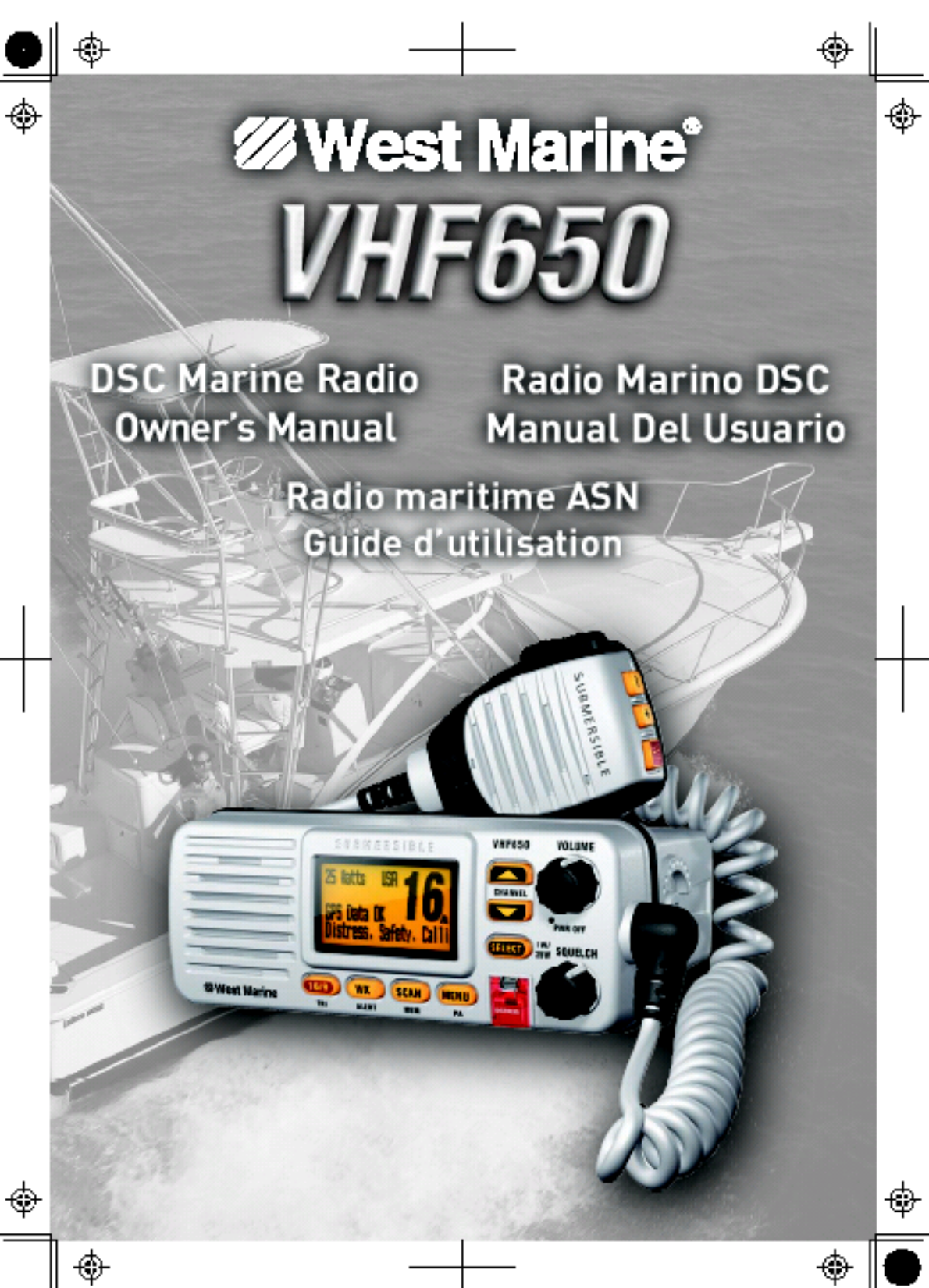
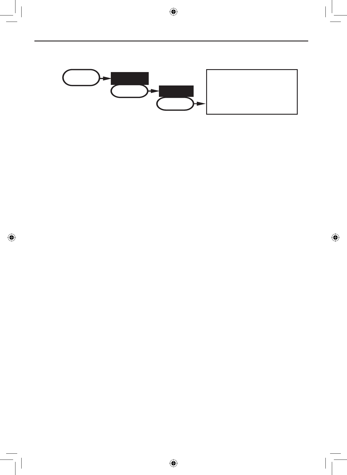
Making a Distress Call
Lift the red cover. Press and hold the
DISTRESS button for three seconds. The
VHF650 transmits your boat’s location
every few minutes until you receive a
response.
NOTE: If the radio displays Enter User
MMSI, cancel the automatic distress call
and make a normal voice distress call.
L
ift the red cover
and press the
DISTRESS
button.
Making a voice distress call
Speak slowly -- clearly -- calmly.
Make sure your radio is on.
On the microphone, press the 16/9-TRI button to switch to Channel 16
(156.8 MHz). (If the corner of the display does not show 16, press the
16/9-TRI button again until it does.)
Press the PUSH TO TALK button on the microphone and say: "MAYDAY
--MAYDAY-- MAYDAY."
Say "THIS IS ___________ ÅWrite your boat’s name in the blank space
Say "MAYDAY ___________ ÅWrite your boat’s name in the blank
space.
Tell where you are: (what navigational aids or landmarks are near, or
read the latitude and longitude from your GPS).
State the nature of your distress, e.g. are you sinking, medical
HPHUJHQF\PDQRYHUERDUGRQ¿UHDGULIWHWF
Give number of persons aboard and conditions of any injured persons.
Estimate present seaworthiness of your ship, e.g. how immediate is the
GDQJHUGXHWRÀRRGLQJRU¿UHRUSUR[LPLW\WRVKRUH
%ULHÀ\GHVFULEH\RXUVKLSOHQJWKW\SHFRORUKXOO
Say: “I will be listening on Channel 16."
End message by saying "THIS IS ___________, OVER." ÅWrite your
boat’s name or call sign in the blank space.
Release the PUSH TO TALK button and listen. If you do not get an answer
after 30 seconds, repeat your call, beginning at step 3, above.
1.
2.
3.
4.
5.
6.
7.
8.
9.
10.
11.
12.
13.
Making a Distress Call

E-2
Table of Contents
Making a Distress Call .................i
Making a voice distress call ........ i
Table of Contents .........................2
Introduction...................................4
Features .....................................4
Manual overview ........................4
Conventions ............................4
Terms used in this manual .......4
Getting Started..............................6
What's included ............................. 6
Parts of the radio ........................... 7
Turning on the radio..................... 10
Setting the UIC channel mode
(USA/CAN/INT) ........................... 10
How it Works...............................10
Normal mode operation............ 11
Using the radio in normal
mode .....................................12
Normal mode with Weather
Alert Watch ............................ 12
Normal mode with Triple and
Dual Watch ............................ 13
Normal mode with both Weather
Alert and Triple/Dual Watch ...13
Scan mode ...............................14
Using the radio in scan
mode .....................................14
Scan mode with Weather Alert
Watch ....................................15
Scan mode with Triple and Dual
Watch ....................................15
Scan mode with both Weather
Alert and Triple/Dual Watch ...16
Weather mode..........................16
Using the radio in weather
mode .....................................16
Weather mode with Weather
Alert Watch ............................ 17
Weather mode with Triple and
Dual Watch ............................ 17
Using Your Radio........................18
Making a voice MAYDAY
call............................................19
Setting the volume ...................19
Setting the squelch level ..........19
Changing the channel ..............20
Making a transmission .............20
Boosting the transmission
power .....................................20
Choosing Triple Watch or Dual
Watch .......................................21
Using FIPS codes for weather
alerts ........................................21
Changing display and sound
options......................................23
Contrast ................................. 20
Lamp adjust ........................... 20
Turning the key beep on and
off ..........................................20
Setting the GPS position
manually...................................23
Using Digital Selective Calling
(DSC) Features............................25
What is DSC?...........................25
Advanced DSC features...........25
Getting an MMSI number .........26
Entering MMSI numbers ..........26
Individual or user MMSI
number ..................................26
Group MMSI number ............. 27
Using the directory ...................28
Making DSC calls.....................30
Calling a single station
(Individual Call) ......................31
Calling a particular group of
stations (Group Call) .............32
Calling all stations (All-Ships
Call) .........................................32
Making an automatic distress
call............................................33
Canceling an automatic
distress call ............................33
Receiving a DSC call ...............34
Receive log ..............................34
Returning a call .....................35
Requesting another station's
position (POS Request) ...........35
Receiving a position request
(Position Reply)........................36
Enabling automatic position
reply .......................................36
Sending your own position
(Position Send)..........................37
Putting the radio into standby....37
Disabling automatic channel
switching....................................38
Renaming Channels...................39
Table of Contents

E-3
Table of Contents (Cont'd)
List of Tables
Table 1 - Terms used in this
manual ............................................5
Table 2 - Rear panel .......................7
Table 3 - Front panel ......................8
Table 4 - Microphone button
connector ........................................9
Table 5 - Normal mode status
messages .....................................12
Table 6&KDUDFWHUDQGWH[WHQWU\
order .............................................29
Table 7 - Receive log ...................35
Table 8 - Common GPS receiver and
connections ..................................45
Table 9 - Radio specifications ......54
Table 10 - Channel by type of
message .......................................56
Table 11 - USA Channel Frequencies
and Channel Tag ..........................57
Table 12 - Canadian Channel
Frequencies and Channel Tag ......59
Table 13 - International Channel
Frequencies and Channel Tag ......61
Table 14 - Weather Channel
Frequencies and Channel Tag ......63
Table 15 - CEA2009-S.A.M.E.
EVENT CODE ..............................63
Table 16 - NMEA Input .................66
Installing the Hardware..............40
Mounting the radio ...................40
Connecting the radio ................42
Connecting accessories ...........44
Connecting to a GPS
receiver ..................................44
Configuring the GPS .............46
Connecting to a charplotter ...47
&RQQHFWLQJWRDQH[WHUQDO
speaker ..................................47
&RQQHFWLQJWRDQH[WHUQDO3$
speaker ..................................48
Using the PA feature ..............49
Maintenance and
Troubleshooting .........................50
Common questions ..................... 51
Engine Noise Suppression.......... 53
Maritime radio services
operation ..................................53
Basic radio guidelines ..............53
Specifications.............................54
Channel by type of message ...... 56
Channel and frequencies ............ 57
Alert codes and event levels ....... 63
NMEA Operation ......................... 66
NMEA Input ............................... 66
NMEA Output ............................ 66
Regulations and Safety Warnings67
FCC and Industry Canada
information ...............................67
Lead warning............................67
Antenna Selection and
Installation ................................67
Three Year Limited Warranty.....68
Mounting Bracket Driling
Template......................................69

E-4
Introduction
Features
Submersible Design
Complies with JIS7 water-resistant standards, which means the radio can
be submerged in 1 meter of water for 30 minutes without damage.
Large, dot matrix display
Advanced DSC Class D functions
Built-in PA feature
Channel select buttons on the microphone
Memory scan mode
Lets you save channels to memory and monitor them in quick succession.
Transmitter Power Level Select
Lets you boost the transmitter power from 1 watt to 25 watts for added
transmission distance.
Battery level display and tone
Sounds an alert tone if the battery voltage goes too high or too low.
Triple Watch Operation
Checks the Coast Guard Distress/Hailing channels 16 and 9 in the
background.
All marine VHF channels for the U.S., Canada, and international
waters
National Oceanic and Atmospheric Administration (NOAA) weather
channel watch
Sounds a warning tone when a hazard alert is issued for your area.
•
•
•
•
•
•
•
•
•
•
•
Manual overview
Conventions
This manual uses several different type styles to help you distinguish
between different parts of the radio:
•BOLD SMALL CAPITALS indicates an actual button or knob on the radio
or microphone.
•Upper and Lower case bold indicates a connector or label on the
radio.
•ItalicsLQGLFDWHWH[WRQWKHGLVSOD\VXFKDVPHQXRSWLRQVSURPSWV
DQGFRQ¿UPDWLRQPHVVDJHV
Introduction
E-5
Introduction
DSC Digital Selective Calling. A VHF radio standard for
communicating among boats and sending automated
distress calls.
FIPS Federal Information Processing Standard. A set of
location codes roughly equivalent to your county
codes.
WX Weather radio
GPS Global Positioning System
NMEA National Marine Electronics Association. The
organization that governs standards for electronic
equipment used on boats. NMEA 0183 is the standard
for serial data communication used by GPS receivers.
MMSI Maritime Mobile Service Identity number. A unique,
QLQHGLJLWQXPEHUWKDWLGHQWL¿HV\RXDQG\RXUERDW
when making DSC calls. It is also used by the Coast
Guard if you send an automated distress call.
Station Any DSC radio, whether it’s operated on a boat, at a
marina, or by a shore station.
Table 1 - Terms used in the manual
Getting Started
E-6
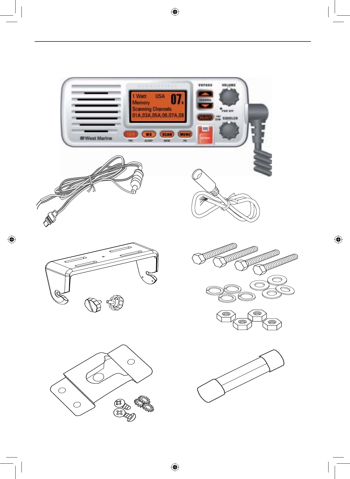
What's included
VHF650 Radio
DC Power Cable Accessory Cable
Mounting Bracket and
knobs Mounting Hardware
Microphone Hanger Spare Fuse 250V 6A
Getting Started
E-7
Getting Started
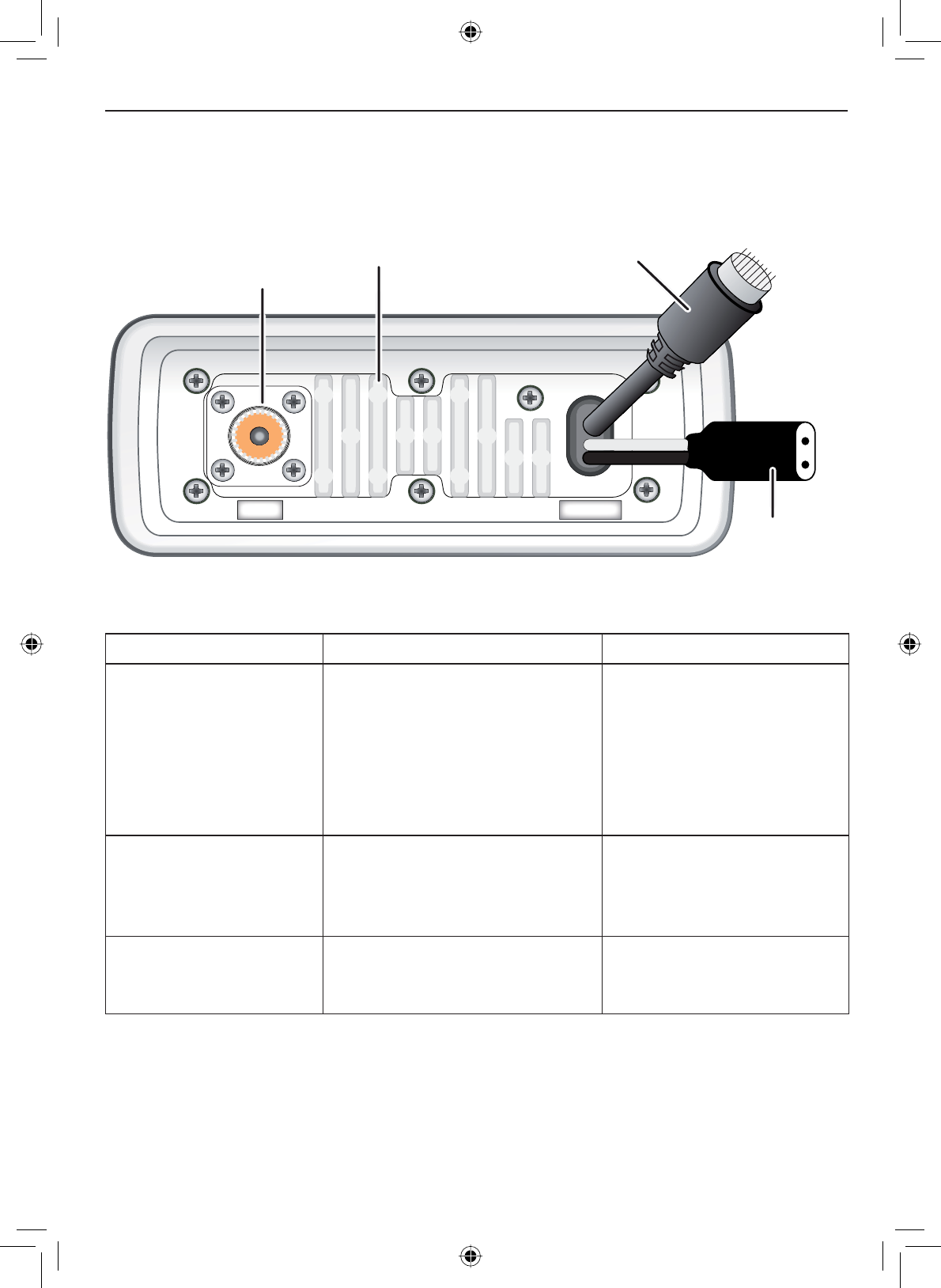
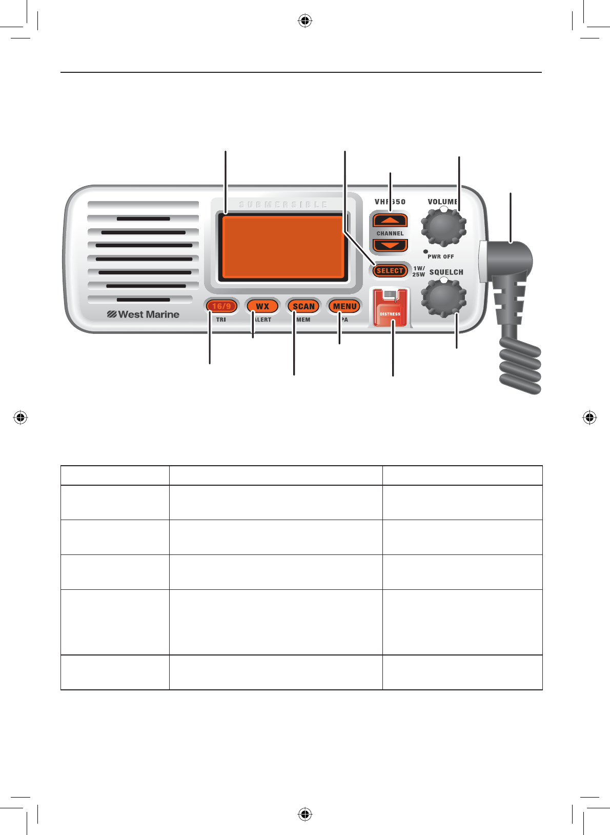
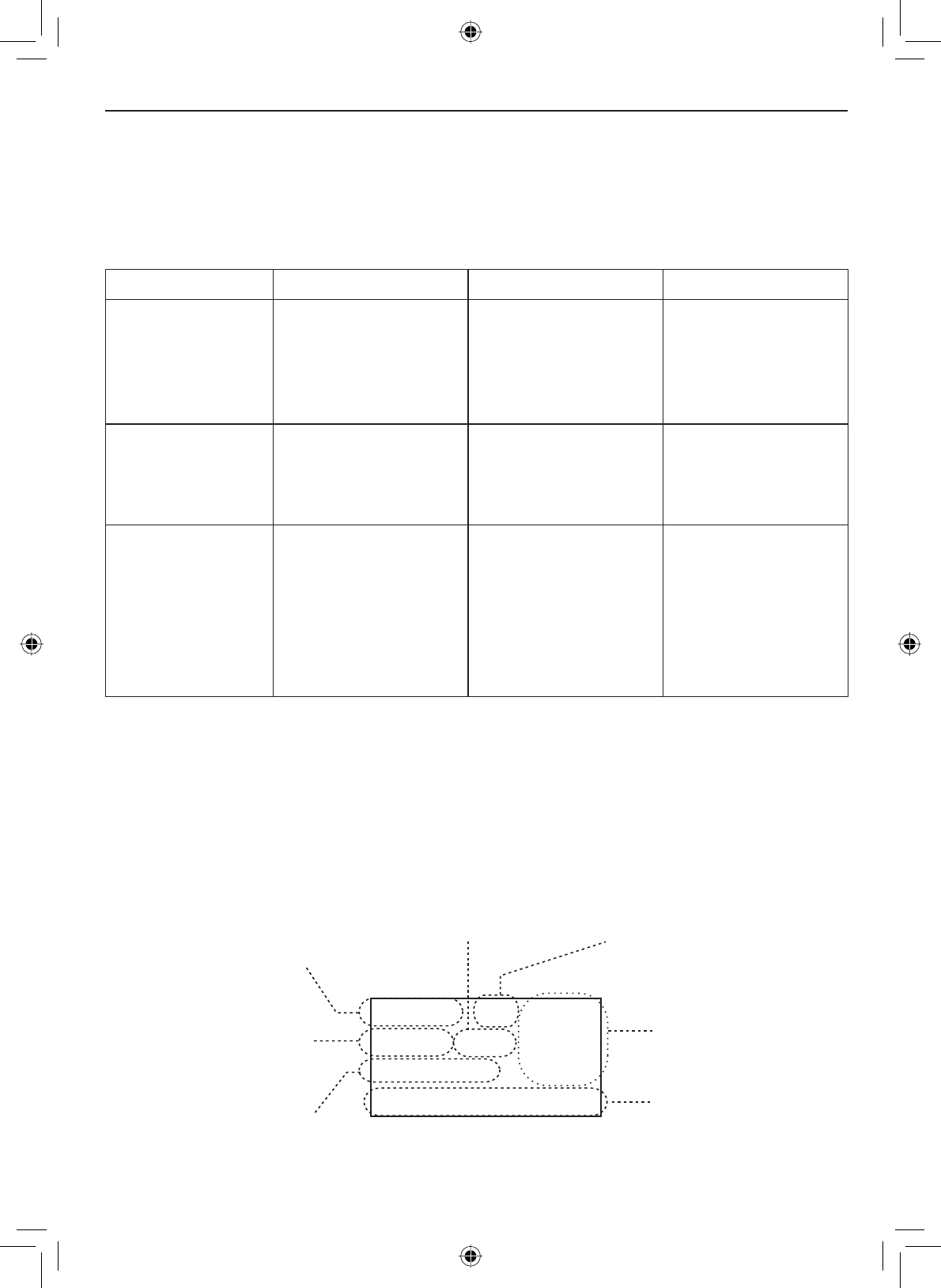
Parts of the radio
13.8V DC
ANTENNA
Antenna
connector
(SO238) Heat sink
Power
connector
Accessory
connector
Table 2 - Rear panel connector functions
Connector Connects to For details, see
Antenna connector ([WHUQDO9+)DQWHQQDZLWK
a male PL259 (SO238)
FRQQHFWRUDQG
impedance.
Minimum 4 ft, 3dB rated
antenna for sailboats, 8 ft, 6
dB rated for power boats.
Connecting the radio,
page 42.
Power connector Nominal 13.8 VDC power
supply with negative ground
(11.7 VDC to 14.3 VDC)
(Red wire +, black wire -).
Connecting the radio,
page 42.
Accessory connector GPS receiver, GPS
FKDUWSORWWHUH[WHUQDOVSHDNHU
H[WHUQDO3$VSHDNHU
Connecting accessories,
page 44.
Getting Started
E-8
07A
1 Watt USA
Memory
Scanning Channels
01A,03A,05A,06,07A,08
LCD
display
SELECT
/
1W/25W
button
CHANNEL UP
&
DOWN
buttons
VOLUME
-
PWR
(power) knob
(turn clockwise
to increase
volume)
Microphone
cord
16/9-
TRI
(triple/
dual-watch)
button
WX
-
ALERT
(weather)
button
SCAN
-
MEM
(channel
memory)
button
MENU
-
PA
(public
address)
button
DISTRESS
button
SQUELCH
knob
(turn clockwise
to decrease
channel noise)
Button Press to... Press and hold to...
SELECT-1W/25W Choose an option on a menu. Change the transmit
power (see page 20).
CHANNEL UP Move up one channel at a time. Move quickly up the
channels.
CHANNEL DOWN Move down one channel at a time. Move quickly down the
channels.
16/9-TRI 1st press: Go to Channel 16.
2nd press: Go to Channel 9.
3rd press: Go back to the original
channel.
Go into Triple Watch or
Dual Watch mode (see
page 13).
DISTRESS Select the nature of your distress
for a distress call.
Transmit a distress call.
Table 3 - Front panel button functions
E-9
Getting Started
Button Press to... Press and hold to...
WX-ALERT Listen to the current weather
conditions in your area.
Monitor the weather
channels for alerts in any
area.
MENU-PA Display the radio menu. Use the public address
(PA) function.
SCAN-MEM Start scanning the channels saved
in memory.
Save a channel into
memory or remove a
channel from memory.
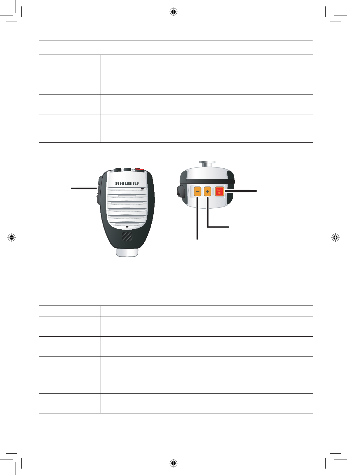
PUSH -
TO-TALK
but
ton
16/9 TRI
(Triple /Dual-
Watch) button
+ (plus) button
(move up a channel)
- (minus) button
(move down a channel)
Table 4 - Microphone button functions
Button Press to... Press and hold to...
+ Move up one channel at a time. Move quickly up the
channels.
- Move down one channel at a time. Move quickly down the
channels.
16/9-TRI 1st press: Go to Channel 16.
2nd press: Go to Channel 9.
3rd press: Go back to the original
channel.
Go into Triple Watch or
Dual Watch mode (see
page 13).
PUSH TO TALK Cancel scanning and stay on a
channel.
Talk on a channel.
Getting Started
E-10
Turning on the radio
Turn the VOLUME-PWR knob clockwise to turn on the radio. As it powers on,
the radio displays the user MMSI number; if there is no MMSI set, the radio
displays MMSI not entered.
When it powers on, the radio selects the last channel used.
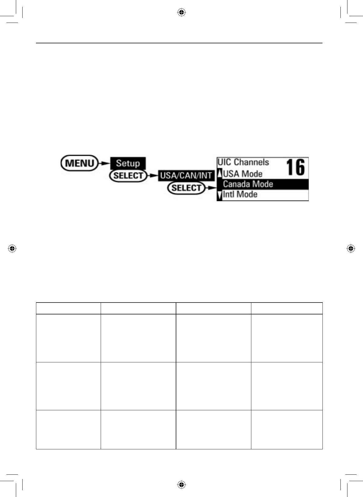
Setting the UIC channel mode (USA/CAN/INT)
The radio comes preset to use the UIC channels assigned for the United
States. If you are operating in an area that uses Canadian or international
UIC channels, you will need to change the channel mode.
Press the MENU-PA button to display the menu, and choose the Setup
sub-menu.
Select USA/CAN/INT. The screen displays the UIC channel setup.
Highlight the channel mode you want to use: US (USA mode),
Canadian (Canada mode), or international (Intl mode).
Press the SELECT-1W/25W button. The radio activates the new channel
PRGHDQGH[LWVWKHPHQX
1.
2.
3.
4.
How It Works
The VHF650 has three basic modes of operation:
Operation mode What it does: Use it when: To turn it on/off:
Normal mode Monitors a single
marine radio
channel and lets
you talk on that
channel.
You want to talk to
another station on a
VSHFL¿FFKDQQHO
(default mode)
Scan mode Monitors all the
channels you save
into memory.
You have a small
group of channels
you use most often
and want to check
WKHPIRUWUDI¿F
Press the SCAN-
MEM button.
Weather mode Monitors the
selected NOAA
weather channel.
You want to hear
the current and
forecasted weather
in your area.
Press the WX-
ALERT button.
E-11
Getting Started
In addition to the three main operation modes, the VHF650 also provides
three different “watch” modes which you can activate during any of the three
EDVLFPRGHV,QWKHZDWFKPRGHVWKHUDGLREULHÀ\FKHFNVIRUDFWLYLW\RQD
VSHFL¿FFKDQQHOWKHQUHWXUQVWRLWVSUHYLRXVPRGH
Watch mode What it does: Use it when: To turn it on/off:
Weather Alert
Watch
Checks for alerts
on the last weather
channel you
used every seven
seconds.
You want to be
made aware of
severe weather
conditions in your
area.
Press and hold the
WX-ALERT button
for two seconds.
Triple Watch Checks for activity
on channels 16
and 9 every two
seconds.
You want to monitor
a channel yet
maintain a watch on
channels 16 and 9.
Press and hold the
16/9-TRI button for
two seconds.
Dual Watch Checks for activity
on channel 16 every
two seconds.
You want to monitor
a channel yet
maintain a watch on
channel 16.
Change Triple
Watch to Dual
Watch in the setup
menu, then press
and hold the 16/9-
TRI button for two
seconds.
NOTE: You are required to monitor channel 16 whenever your boat is under-
way. You should have either Triple Watch or Dual Watch on at all times.
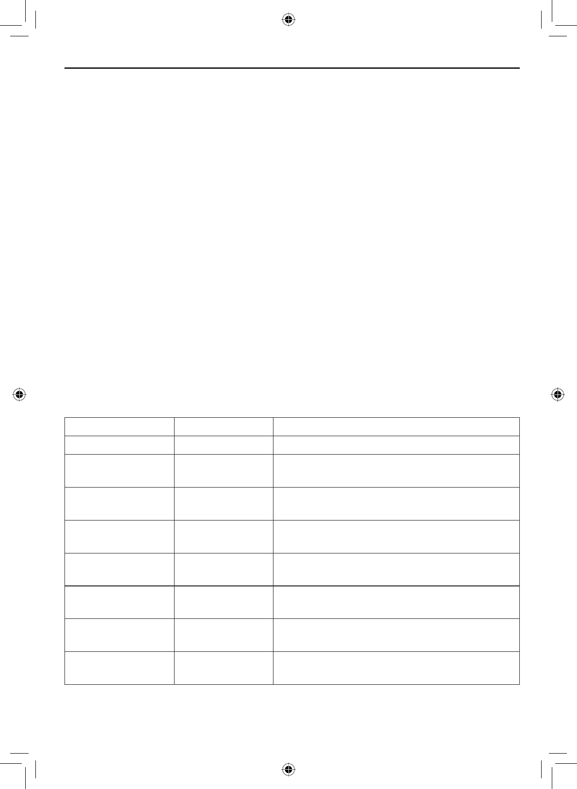
Normal mode operation
Normal mode monitors whatever channel you select, and you can transmit on
that channel also.
While using normal mode, the display lets you see the following information
(not all indicators will display at the same time):
25
Marine Operator
25 Watts USA
Memory Alert
GPS Data OK
Transmit power
(1 W or 25 W)
Current channel
is stored in
memory
S
tatus messages
(see the status
message table )
Current
channel
number
Current channel
name (if the name
is too long, the
name line scrolls)
Channel mode
(USA,CANadian,
or INTernational)
Weather Alert
Watch on
Getting Started
E-12
Table 5 - Normal mode status messages
Message Meaning
GPS Data OK The radio is receiving valid GPS data.
Check GPS The radio is not receiving valid GPS data: check the GPS status screen and
the GPS connection.
Input Position The radio has been unable to receive valid GPS data for at least four hours;
it can no longer track your position. You need to manually input your position
(see Setting the GPS position manually on page 24).
Battery Low The battery voltage output is too low (below 11.2 VDC).
Battery High The battery voltage output is too high (above 14.8 VDC).
Triple Watch Triple Watch is turned on.
Dual Watch Dual Watch is turned on.
Using the radio in normal mode
• To transmit, press and hold the PUSH TO TALK button on the
PLFURSKRQH5HOHDVHWKHEXWWRQZKHQ\RXDUH¿QLVKHGWDONLQJ
• For the best sound quality, hold the microphone about two inches from
your mouth while you’re talking.
• Press the CHANNEL UP button on the radio or the + button on the
microphone to move up one channel at a time. Press and hold either
button to scroll quickly up the channels.
• Press the CHANNEL DOWN button on the radio or the - button on the
microphone to move down one channel at a time. Press and hold
either button to scroll quickly down the channels.
• To change the transmit power, press and hold the SELECT-1W/25W
button for two seconds. The transmit power switches between 1 watt
and 25 watts each time you press and hold the SELECT-1W/25W button.
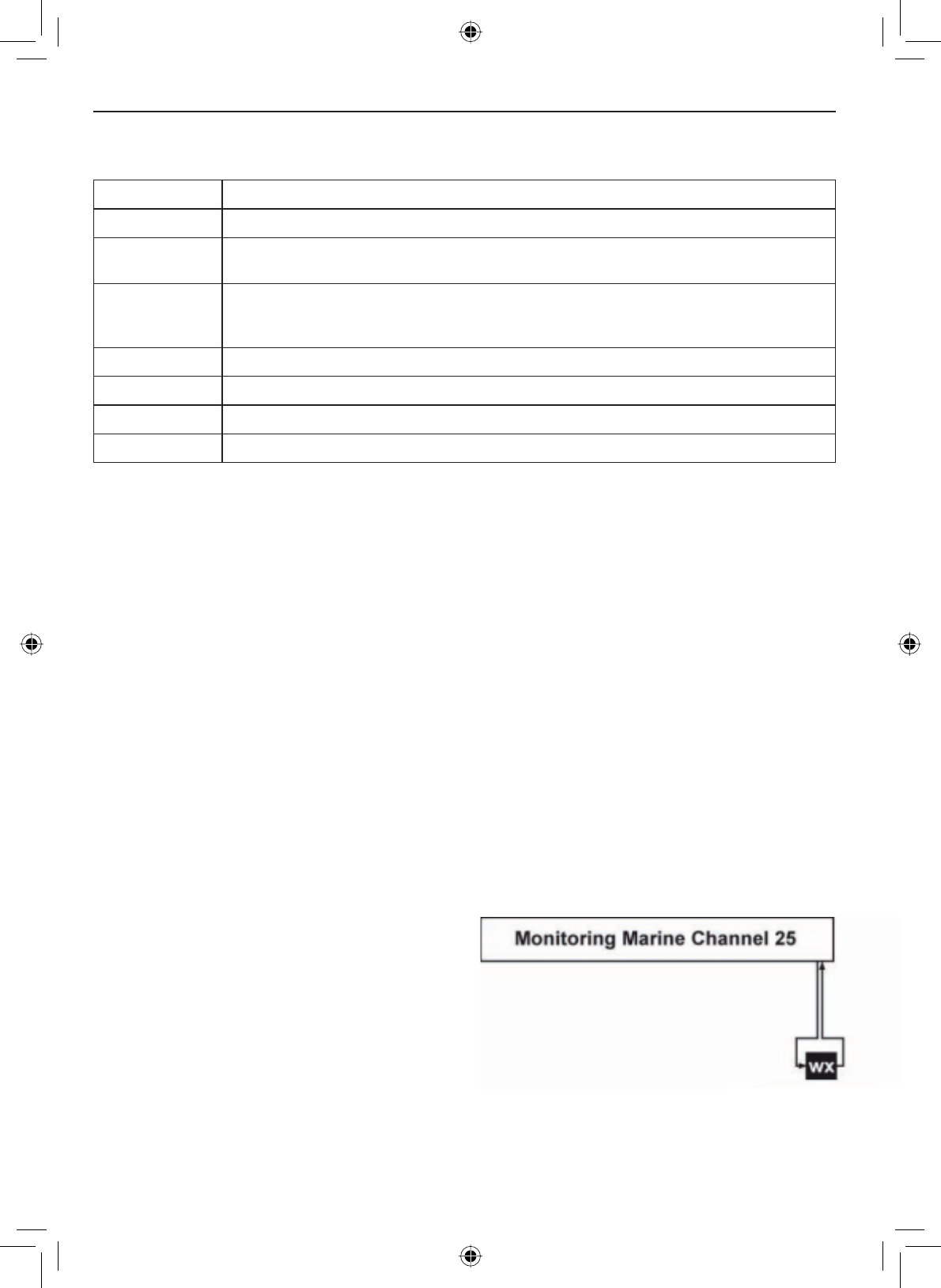
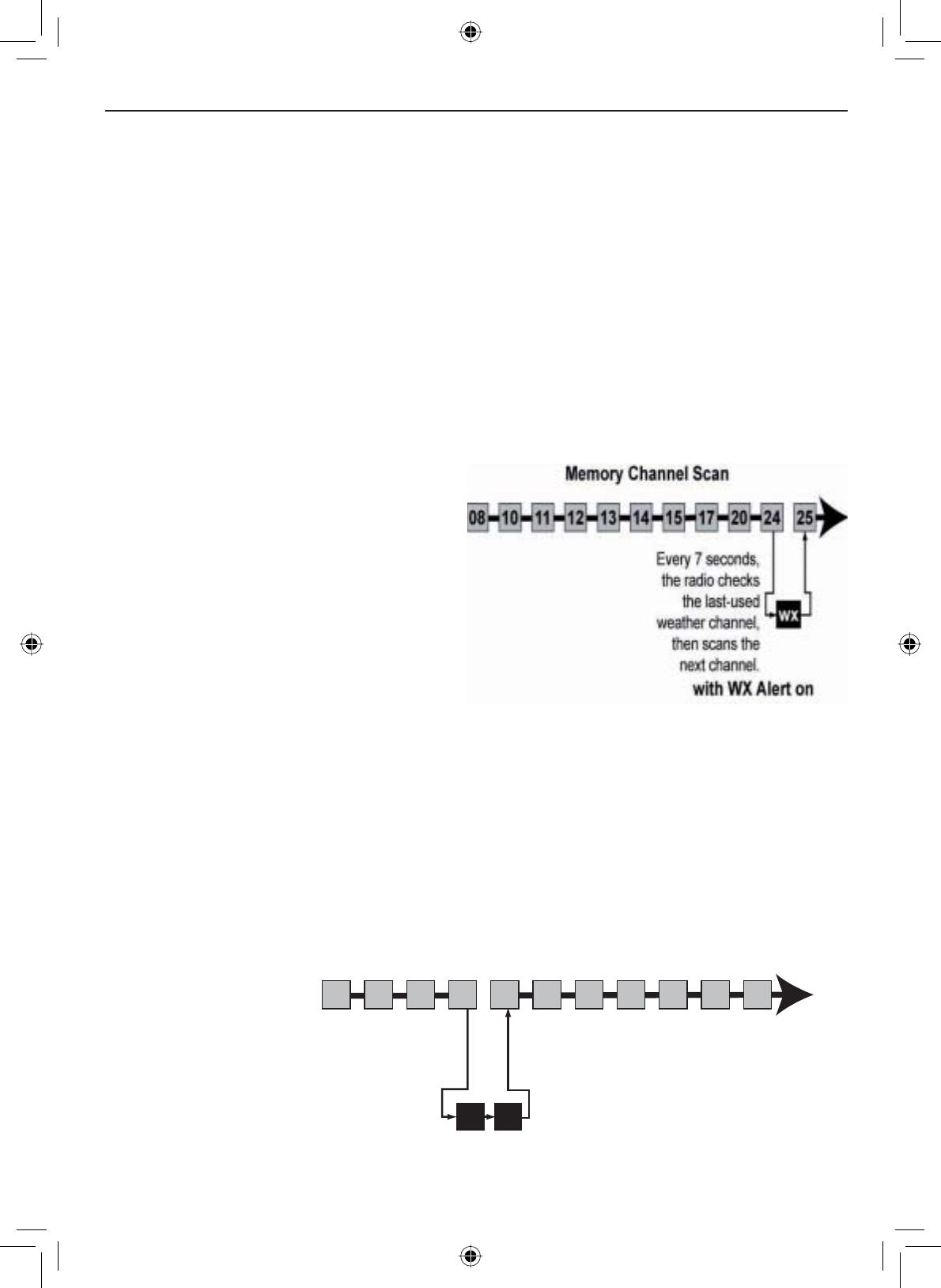
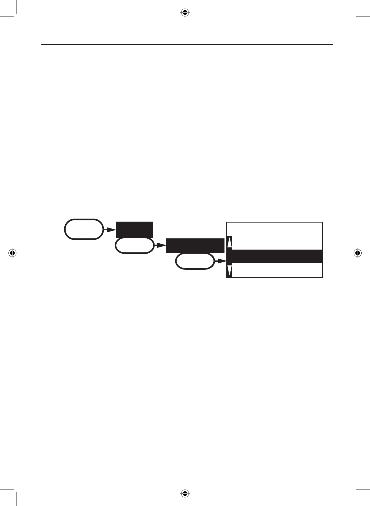
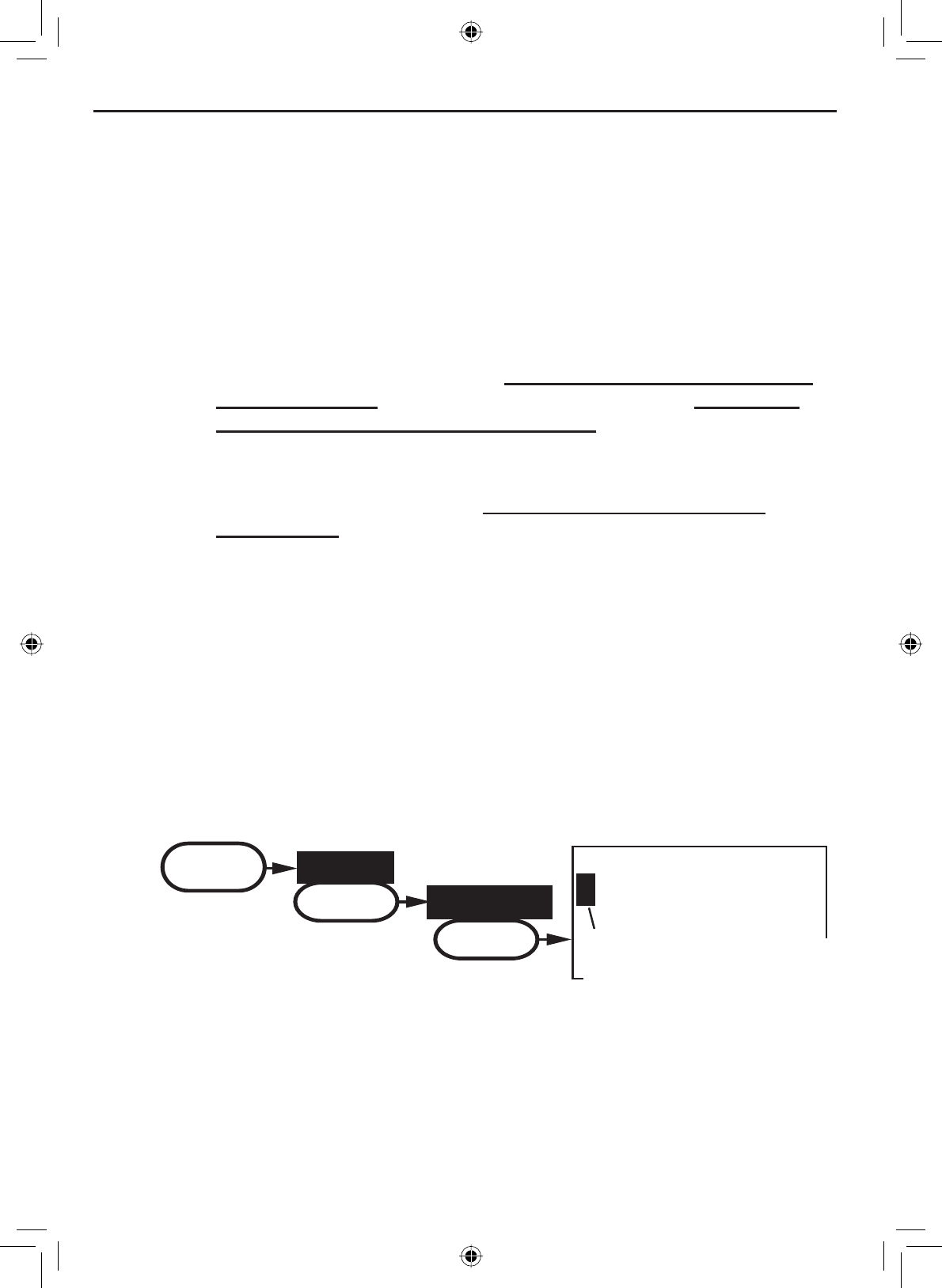
Normal mode with Weather Alert Watch
If you activate Weather Alert Watch
while operating in normal mode,
the radio checks the most recently-
used weather channel every seven
seconds. If it detects a weather
alert for your area, it will change the
channel to the last-used weather
channel. The radio will not check
the weather channel while you are actively transmitting; it waits until your
WUDQVPLVVLRQLV¿QLVKHGDQGWKHQFKHFNVWKHZHDWKHUFKDQQHO
Every 7 seconds, the
radio checks the most
recently-used weather
channel. with WX
Alert on
E-13
Getting Started
Press and hold the WX-ALERT button for two seconds to turn Weather Alert
Watch on or off.
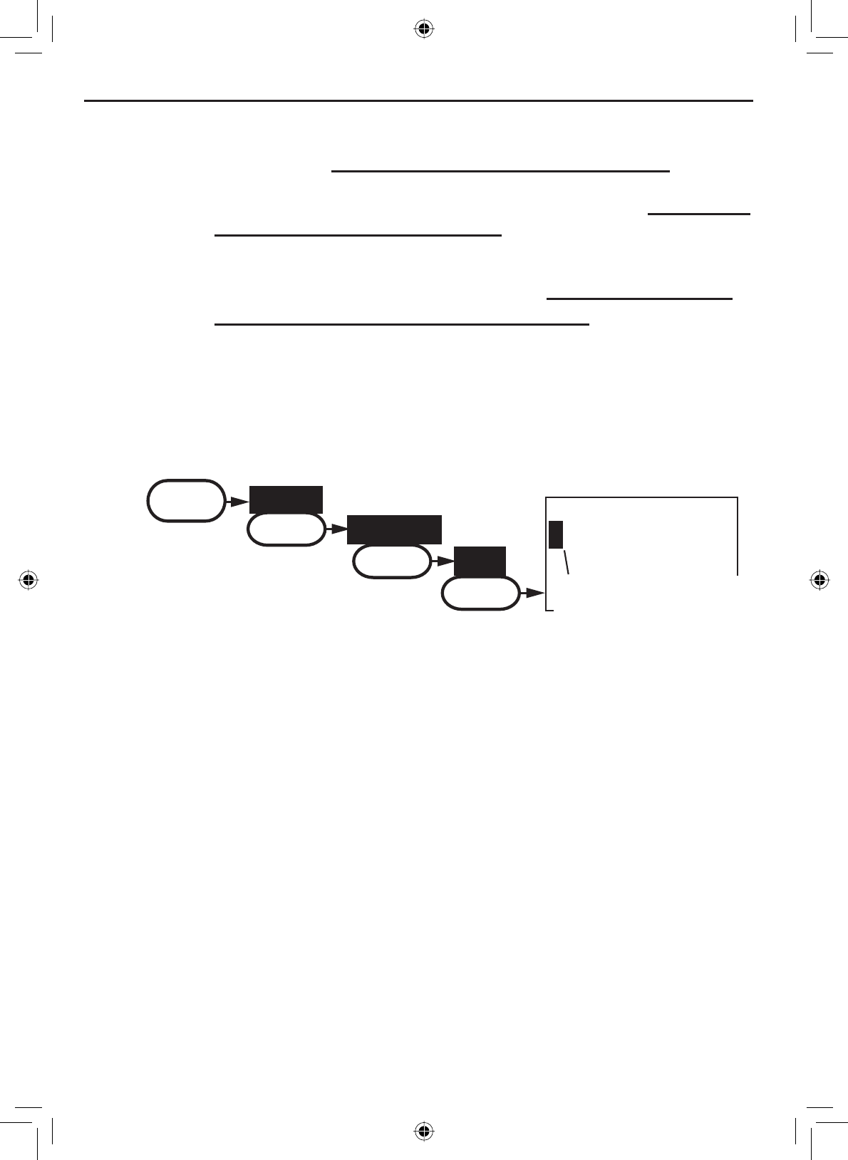
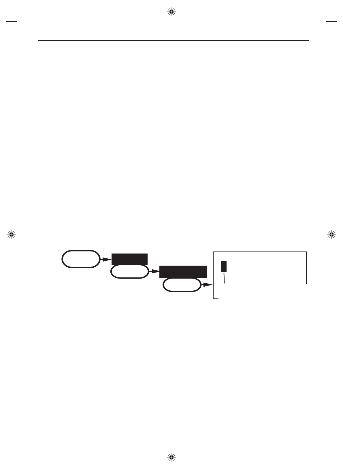
09 16 09 16 09 16
Every 2 seconds, the radio
checks channels 9 & 16.
with Triple Watch on
Monitoring Channel 25
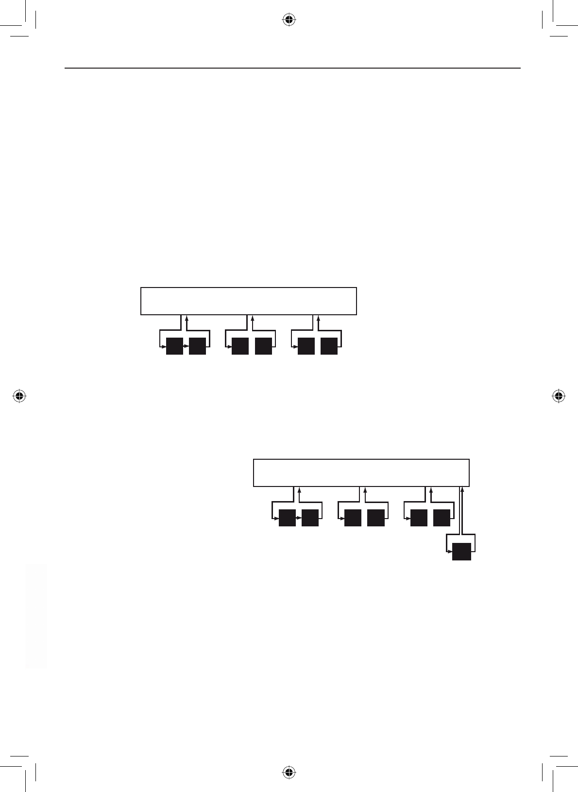
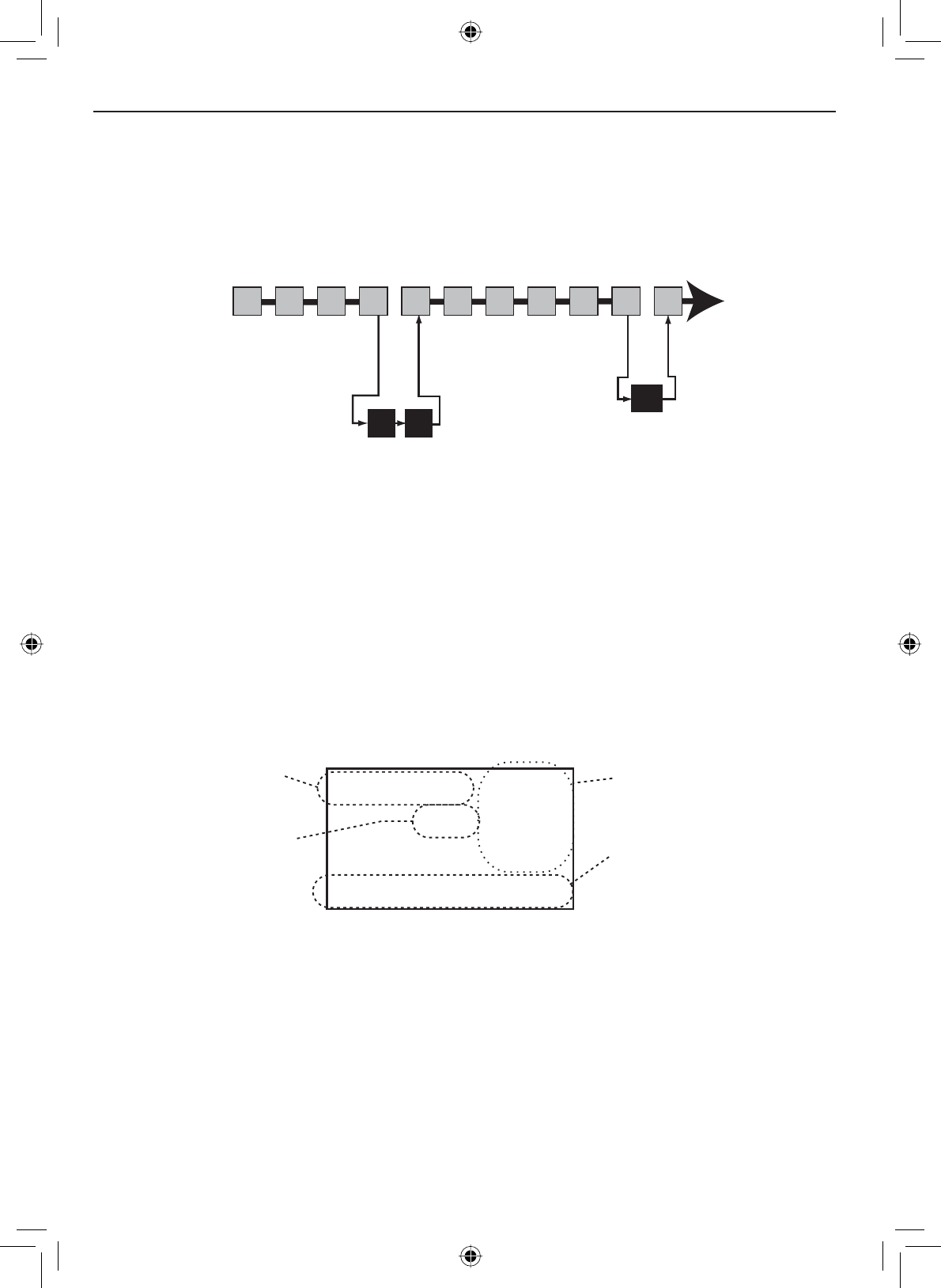
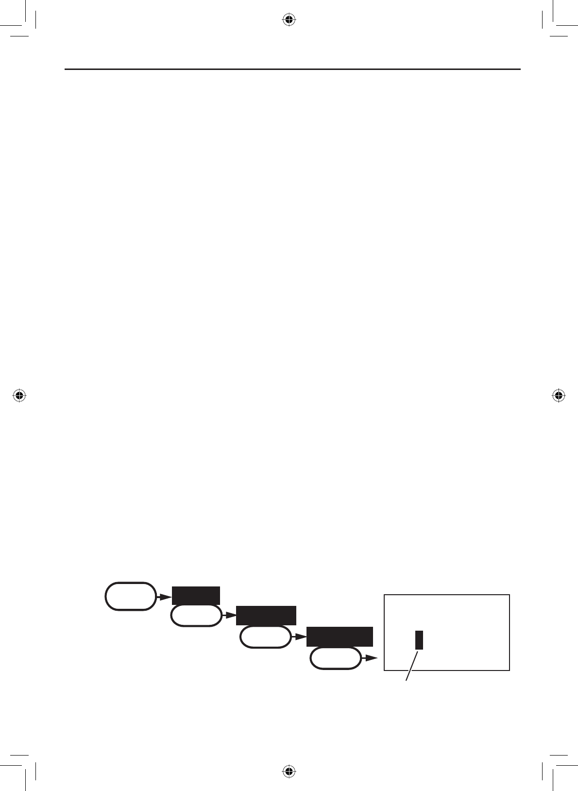
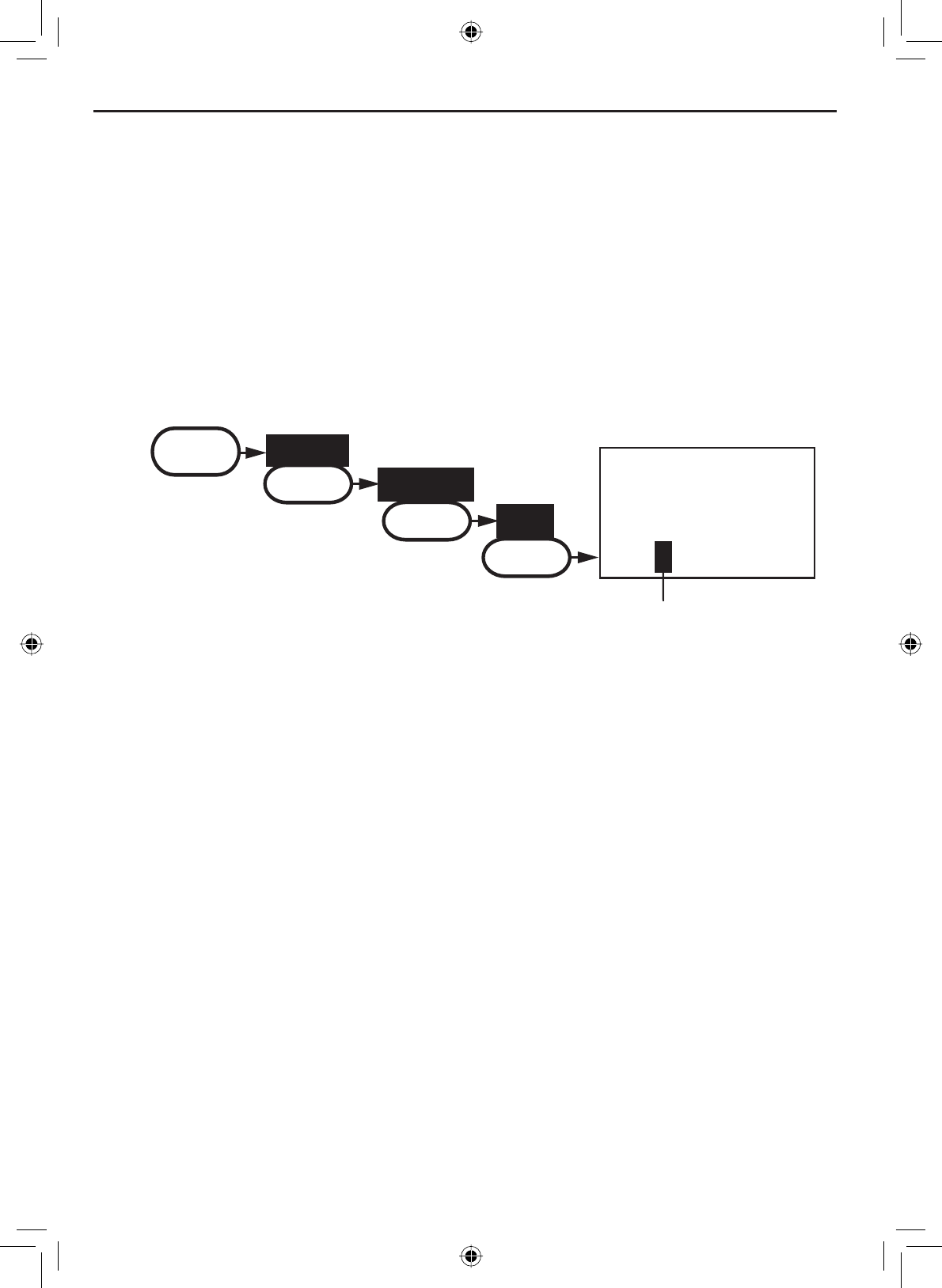
Normal mode with both Weather Alert and Triple/Dual Watch
wx
Every 7 seconds,
the radio checks the
most recently-used
weather channel.
with WX Alert on
09 16 09 16 09 16
Every 2 seconds, the radio
checks channels 9 & 16.
with Triple Watch on
Monitoring Channel 25
Press and hold the 16/9-TRI button (on the radio or the microphone) for two
seconds to turn Triple/Dual Watch on or off. (To change between Triple or
Dual Watch, see page 21.)
Normal mode with Triple and Dual Watch
If you activate Triple Watch while operating in normal mode, the radio checks
channels 16 and 9 every two seconds; with Dual Watch turned on, the radio
only checks channel 16. The radio will not check channels 16 or 9 while you
DUHDFWLYHO\WUDQVPLWWLQJLWZDLWVXQWLO\RXUWUDQVPLVVLRQLV¿QLVKHGDQGWKHQ
checks the channels.
You can activate Weather
Alert Watch and Triple/
Dual Watch at the same
time. The radio performs
both checks at their
scheduled time:
Getting Started
E-14
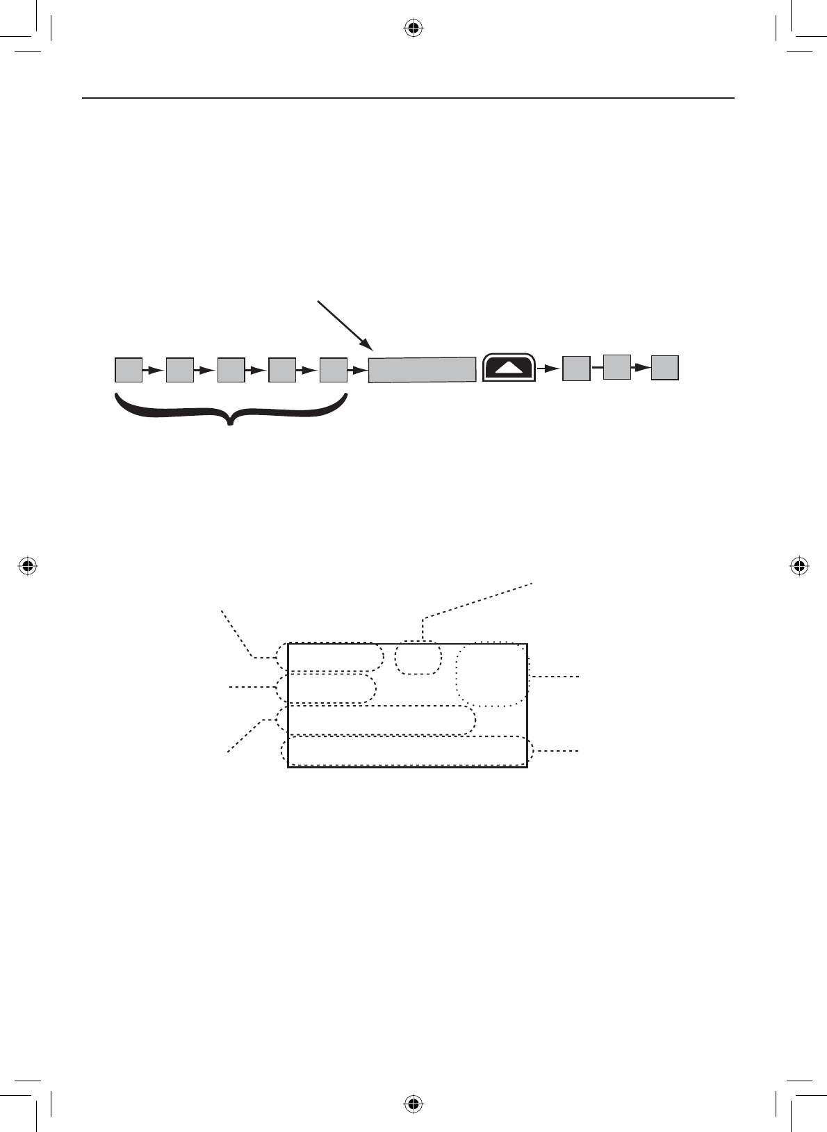
Scan mode
You can save channels into memory and then use scan mode to monitor
those channels. When the radio detects a signal on a channel, it pauses on
that channel as long as the signal is received; when the transmission stops,
the radio will continue scanning.
11
10
0
8 1312 17
15 20
14
The radio scans about
5 channels in 1 second.
When it detects a signal, the radio stays on the
channel until you press the
CHANNEL UP
button or the
signal stops.
Resume scan
In scan mode, you can get the following information from the display (some
indicators will not always be displayed):
1 Watt USA
Memory
Scanning Channels
01A,03A,05A,06,07A,08
07
T
ransmit power
last used
Channel mode
(USA,CANadian,
or INTernational)
Current
channel being
scanned
Scan list (if the
text is too long,
the line scrolls)
All scanned
channels must
be in memory
Normal scan
mode or Triple /
Dual-watch on
Using the radio in scan mode
You cannot transmit while in scan mode.
You must have two or more channels in memory to start a scan.
To save a channel into memory, select the channel, then press and
hold the SCAN-MEM button for two seconds. Memory will show on the
display.
•
•
•
E-15
Getting Started
To remove a channel from memory, set the radio to that channel, then
press and hold the SCAN-MEM button for two seconds. Memory will no
longer show on the display.
To activate scan mode, press the SCAN-MEM button. Press the SCAN-
MEM button again to return to the previous mode.
When the radio automatically stops on a channel, press the CHANNEL
UP button to leave that channel and resume scanning.
To end the scan, press the microphone PUSH TO TALK button or the
SCAN-MEM button. The radio remains on the last scanned channel.
•
•
•
•
If you activate Weather Alert
Watch while operating in scan
mode, the radio checks the most
recently-used weather channel
every seven seconds, then
FRQWLQXHVVFDQQLQJWKHQH[W
channel in memory:
Press and hold the WX-ALERT button for two
seconds to turn Weather Alert Watch on or
off.
Scan mode with Triple and Dual Watch
If you activate Triple Watch while
operating in scan mode, the radio
checks channels 16 and 9 every
two seconds, then goes on to
VFDQWKHQH[WFKDQQHOZLWK'XDO
Watch turned on, the radio only
checks channel 16:
09 16
E
very 2 seconds,
the radio checks
channels 9 & 16
then goes on to
t
he next channel.
with Triple Watch on
Memory Channel Scan
08 252417151413121110 20
Press and hold the 16/9-TRI button (on
the radio or the microphone) for two
seconds to turn Triple/Dual Watch on or
off. (To change between Triple or Dual
Watch, see page 21.)
Scan mode with Weather Alert Watch
Getting Started
E-16
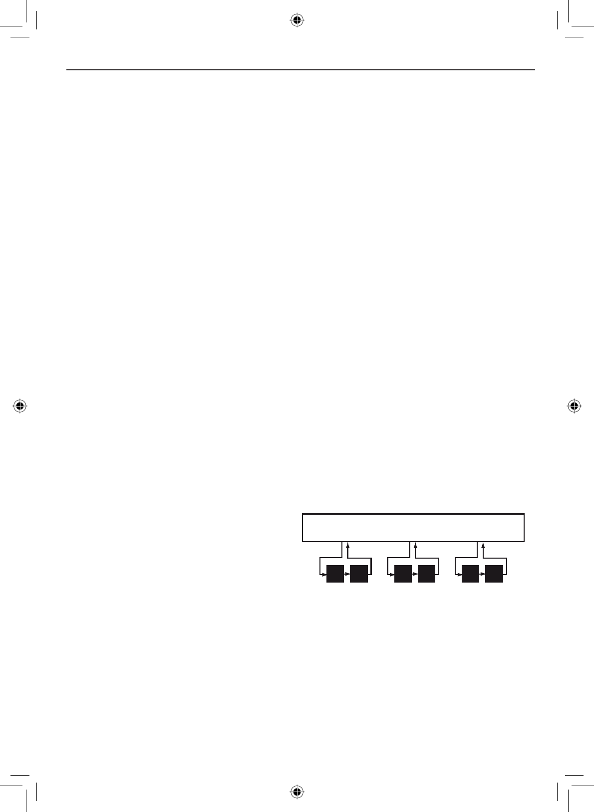
Scan mode with both Weather Alert and Triple/Dual Watch
You can activate Weather Alert Watch and Triple/Dual Watch at the same
time. The radio performs both checks at their scheduled time:
09 16
E
very 2 seconds,
the radio checks
channels 9 & 16
then goes on to
t
he next channel.
with Triple Watch on
Every 7 seconds,
the radio checks
the last-used
weather channel,
then scans the
next channel.
wx
with WX Alert on
Memory Channel Scan
08 252417151413121110 20
Weather mode
In cooperation with the FCC, NOAA also uses the weather channels to
alert you of other hazards besides weather (child abduction alerts, nuclear,
biological, etc.). In weather mode, the radio monitors one of the ten NOAA
weather channels. If any type of alert is received for your area, the radio
sounds an alert tone and displays the type of alert. In weather mode, the
display shows the following:
09
Hurricane Warning
Weather Band
Alert
Weather
mode is on Current
channel
number
Type of alert (if the
text is too long, the
line scrolls)
Fla
shing: An alert
has been issued
Steady: Weather
Alert Watch is on
Using the radio in weather mode
You cannot transmit while in weather mode.
To enter weather mode, press the WX-ALERT button.
:HDWKHUPRGHFDQ¿OWHURXWDOHUWVWKDWGRQRWDIIHFW\RXUORFDWLRQLI
the location code (FIPS code) of the alert is entered in your radio (see
page 21). If you have no FIPS codes programmed into your radio, the
radio will notify you of all alerts in any area.
•
•
•
E-17
Getting Started
Weather mode with Weather Alert Watch
Because weather mode already monitors the weather channels, you don’t
need Weather Alert Watch to check the weather channel every seven
seconds. If you activate Weather Alert Watch while operating in weather
mode, it operates as a type of “sleep mode”: the radio stays on the weather
channel and mutes the speaker. If an alert is detected for your area, the
radio sounds an alert tone and turns the speaker back on. This mode is very
useful when you are anchoring for the night but want to stay informed of any
hazards in your area.
Press and hold the WX-ALERT button for two seconds to turn Weather Alert
Watch on or off.
Weather mode with Triple and Dual Watch
If you activate Triple Watch while operating in weather mode, the radio
checks channels 16 and 9 every two seconds; with Dual Watch turned on, the
radio only checks channel 16.
To turn off the radio’s alert tone, press any button.
To cancel weather mode and return to the previous marine channel,
press the WX-ALERT button again.
•
•
Press and hold the 16/9-TRI button (on the radio or the microphone) for two
seconds to turn Triple/Dual Watch on or off. (To change between Triple or
Dual Watch, see page 21.)
09 16 09 16 09 16
Every 2 seconds, the radio checks
channel 9, then channel 16
with Triple Watch on
Monitoring Weather Channel WX08

Using Your Radio
E-18
Individual
Group
All Ships
POS Request
Position Send
Directory
Standby
Receive Log
Exit
USA/CAN/INT
Dual/TriWatch
GPS Setup
FIPS
Auto CH SW
POS Reply
Channel Name
Group MMSI
User MMSI
Exit
Contrast
Lamp Adjust
Key Beep
Exit
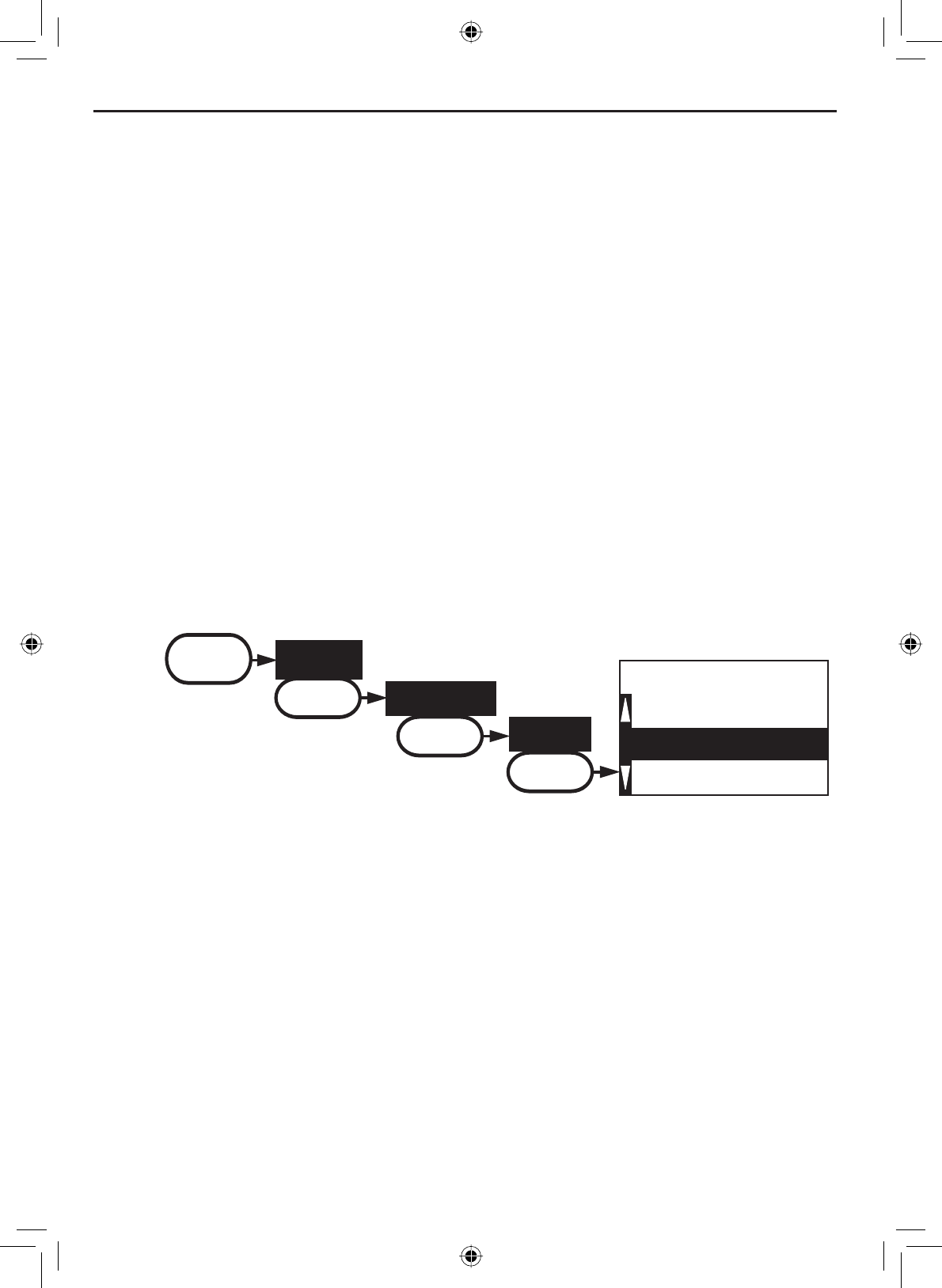
MENU DSC Call SELECT
Setup SELECT
System SELECT
(Close Menu)
Exit SELECT
Using Your Radio
To display the radio menu, press the MENU-PA button. The menu has the
following options:
E-19
Using Your Radio
7KHFXUUHQWO\VHOHFWHGLWHPLVKLJKOLJKWHGLQUHYHUVHGRXWWH[W
Press the CHANNEL UP button on the radio or the + button on the micro-
phone to move up a line in the menu; if you are at the top line in the
menu, the cursor jumps to the bottom of the menu.
Press the SELECT-1W/25W button to choose the selected item.
Press the CHANNEL DOWN button on the radio or the - button on the
microphone to move down a line in the menu; if you are at the bottom
line of the menu, the cursor jumps to the top of the menu.
Press the MENU-PA button to go back to the previous menu screen.
From any menu screen, choose Exit or press the 16/9-TRI button to
close the menu screen.
•
•
•
•
•
•
Making a voice MAYDAY call
(see inside front cover)
Turn the volume knob clockwise to increase the speaker volume; turn it
counter-clockwise to decrease the volume.
Setting the volume
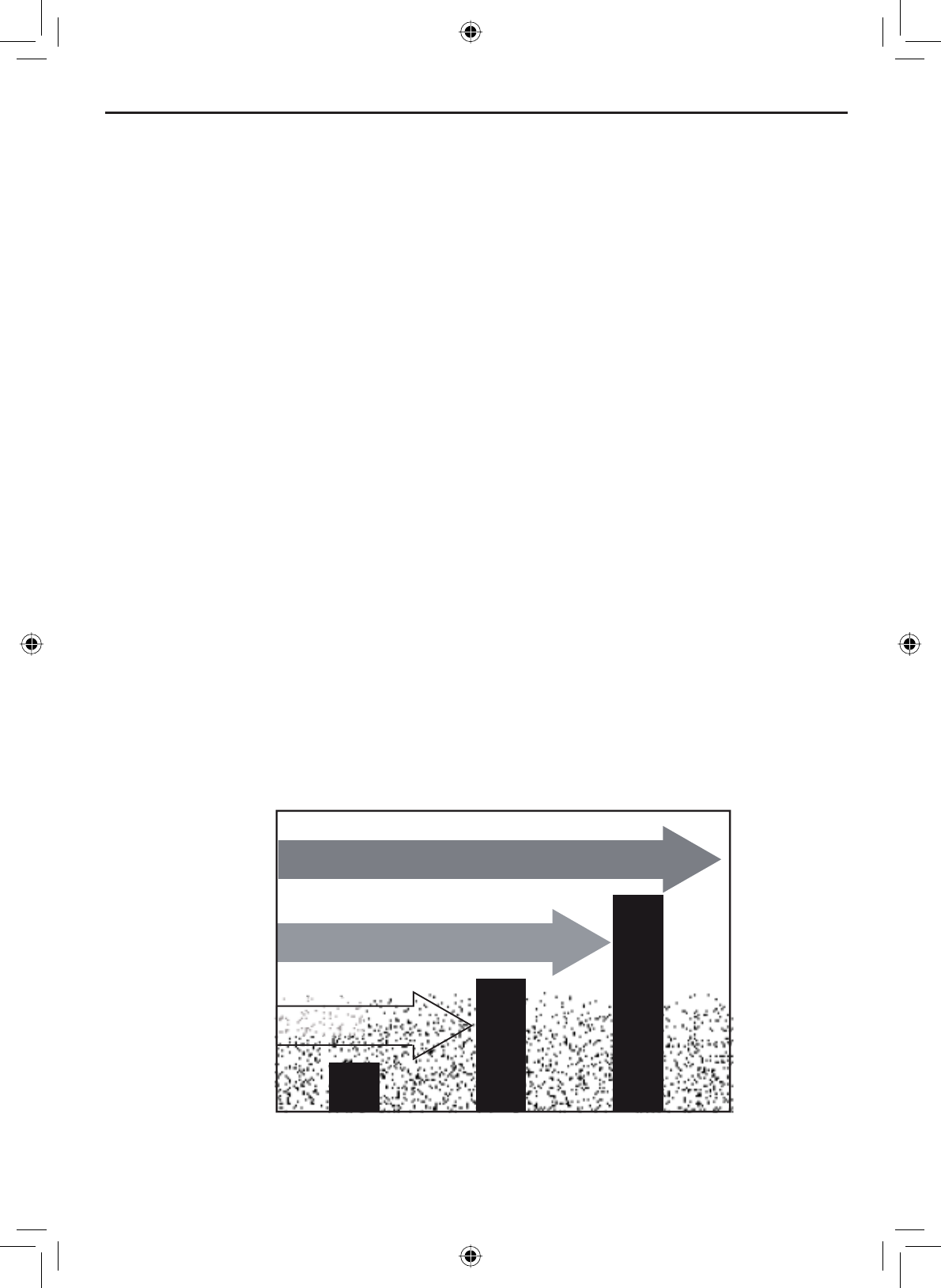
Setting the squelch level
7KHVTXHOFKIHDWXUHUHGXFHVWKHOHYHORIVWDWLFRQWKHVSHDNHUE\¿OWHULQJRXW
the background channel noise. At the lowest squelch level, the speaker plays
all radio signals, including any noise on the channel. Setting the squelch
OHYHOKLJKHU¿OWHUVRXWFKDQQHOQRLVHDQGOHWVRQO\DFWXDOUDGLRWUDQVPLVVLRQV
through.
Weak signals
No
Squelch Medium
Squelch High
Squelch
Strong signals
Noise

Using Your Radio
E-20
While listening to a channel, adjust the SQUELCH knob until the noise is
¿OWHUHGRXWDQG\RXFDQRQO\KHDUWKHWUDQVPLVVLRQ,I\RXVZLWFKWRDFKDQQHO
with a lot of noise or with a weak transmission, you may need to adjust the
squelch level again.
NOTE: Setting the squelch level too high may prevent you from hearing
ZHDNHUWUDQVPLVVLRQV,I\RXDUHKDYLQJGLI¿FXOW\KHDULQJDWUDQVPLVVLRQWU\
setting the squelch level lower.
Changing the channel
Press the CHANNEL UP and CHANNEL DOWNEXWWRQVEULHÀ\WRVFUROOWKURXJK
the channels one channel at a time. Press and hold the channel up or down
button to quickly scroll through the channels.
Making a transmission
To make a transmission, press and hold the microphone PUSH TO TALK button.
Release the PUSH TO TALKEXWWRQZKHQ\RXUH¿QLVKHGWDONLQJWROHWWKHRWKHU
party respond.
To prevent stuck microphone problems or situations where the PUSH
TO TALK button is pushed accidentally, the radio limits your talk time
to 5 minutes in a single transmission. If you talk for over 5 minutes
continuously, the display shows RELEASE MIC BUTTON.
For the best sound quality, hold the microphone about two inches away
from your mouth.
You cannot transmit while the radio is in weather mode or scan mode.
See the channel list on page 57 for a list of receive-only channels.
•
•
•
•
Boosting the transmission power
,QPRVWVLWXDWLRQVWKH:DWWWUDQVPLVVLRQSRZHULVDOO\RXQHHG,I\RX¿QG
yourself far away from other stations and have trouble getting a response,
you may need to boost the transmission power from 1 Watt to 25 Watts:
Select the channel you want to transmit on.
Push and hold the SELECT-1W/25W button for two seconds. The
display shows 25 Watts in the upper left hand corner.
The transmit power remains at 25 Watts until you change the setting
back. Push and hold the SELECT-1W/25W button for two seconds. The
display shows 1 Watt.
NOTE: Don’t forget to change the transmission setting back to 1 Watt when
you move closer to other stations.
1.
2.
3.
E-21
Using Your Radio
NOTE: By default, when you change to channel 16, the radio automatically
boosts the power to 25 Watts. Be sure to change the power back to 1 Watt if
you are not making an emergency transmission.
6RPHFKDQQHOVIRUH[DPSOHFKDQQHOVDQGOLPLWWKHSRZHURI
transmission to 1 Watt so that there is less interference between boaters
attempting to use the channel at the same time. If you switch to one of these
channels, the radio changes back to 1 Watt automatically. See the channel
list on page 57 for a list of power-restricted channels.
Choosing Triple Watch or Dual Watch
,Q7ULSOH:DWFKPRGHWKHUDGLREULHÀ\FKHFNVFKDQQHOVDQGHYHU\WZR
seconds. In Dual Watch mode, the radio checks channel 16 only. Generally,
Triple Watch is used in areas where channel 9 is used as a hailing frequency,
while Dual Watch is used in areas where channel 16 is used for distress and
hailing. Your radio comes set to use Triple Watch; if you want to use Dual
Watch instead, you will have to select it in the setup:
88
A
Dual Watch
Triple Watch
[Exit]
Dual/TriWatch
MENU Setup
SELECT
Dual/TriWatch
SELECT
Press the MENU-PA button to display the menu.
Select Setup and then Dual/Tri Watch.
Highlight Dual Watch and press the SELECT-1W/25W button. The radio
activates the new setting and returns to the Setup menu.
To reactive Triple Watch, repeat the procedure described above, but
choose Triple Watch in step 3.
1.
2.
3.
4.
Using FIPS codes for weather alerts
The US National Weather Service established 6-digit Federal Information
3URFHVVLQJ6\VWHP),36FRGHVWRLVVXHZHDWKHUDOHUWVLQVSHFL¿FDUHDV
You can choose which areas you want to hear alerts for by entering these
FIPS codes in your radio. This can prevent you from being bothered by
events that are far from where you are boating. The radio only sounds the
alert tone if an incoming FIPS code matches one of the areas you selected.
Using Your Radio
E-22
• For more information about how the NWS uses FIPS codes, see the
NWS website: ZZZQZVQRDDJRYQZUQZV¿SVFKJKWm.
7RVHHDQLQGH[RI),36FRGHVE\VWDWHVHHWKHZHEVLWHRIWKH
National Institute of Standards and Technology (NIST): www.itl.nist.
JRY¿SVSXEVFRFRGHVVWDWHVKWm.
For information on the Canadian implementation of FIPS
codes, called Canadian Location Codes, see the website of the
Meteorological Service of Canada (MSC): http://www.msc.ec.gc.
ca/msb/weatheradio/transmitter/index_e.cfm
NOTE: If you travel outside the areas you have entered into your radio, you
may not hear alerts that affect your new location. Be sure to enter the FIPS
codes of all the areas you plan to travel to during this trip.
Follow the steps below to edit the list of FIPS codes. You can store up to 30
different FIPS codes in your radio.
•
16
00000
FIPS Code
Use the up and down
arrows to adjust each of
the six digits in turn.
MENU Setup
SELECT
FIPS Codes
SELECT
New
SELECT
Display the menu and choose the Setup sub-menu.
Select FIPS Codes. The screen displays any previously-entered FIPS
codes.
To add a new FIPS code, select New.
Use the CHANNEL UP and CHANNEL DOWNEXWWRQVWRFKDQJHWKH¿UVW
RIWKHVL[GLJLWVWKHCHANNEL UP button increases the number and the
CHANNEL DOWN button decreases the number.
:KHQWKH¿UVWGLJLWLVFRUUHFWSUHVVWKHSELECT-1W/25W button. The
FXUVRUPRYHVWRWKHQH[WGLJLW(QWHUWKHUHPDLQLQJ¿YHGLJLWVRIWKH
FIPS code in the same way.
:KHQWKHVL[WKGLJLWLVFRUUHFWSUHVVWKHSELECT-1W/25W. The radio
GLVSOD\VWKHQHZ),36FRGHDQGDVNV\RXWRFRQ¿UP7RVDYHWKLV
code, select Yes; to cancel this code, select No. The radio returns to
the list of FIPS codes.
7RFKDQJHDQH[LVWLQJ),36FRGHVHOHFWWKHFRGH\RXZDQWWRFKDQJH
1.
2.
3.
4.
5.
6.
7.
E-23
Using Your Radio
To delete the FIPS code, select Delete. To edit the code, select Edit,
then use the CHANNEL UP and CHANNEL DOWN buttons to change each
RIWKHVL[GLJLWV
:KHQ\RXDUHVDWLV¿HGZLWKWKHOLVWRI),36FRGHVVHOHFWExit to close
the menu screen.
8.
9.
Changing display and sound options
Contrast
The VHF650 display has 10 levels of contrast. To adjust the contrast, press
the MENU-PA while the radio is idle. Select System and then Contrast. Use
the CHANNEL UP and CHANNEL DOWN buttons to change the contrast to your
desired level.
To restore the default contrast setting, turn the radio off. Press the MENU-PA
button and hold it in while you turn the radio on.
Lamp adjust
The VHF650 has 10 brightness levels on the display. To adjust the
brightness, press the MENU-PA button while the radio is idle. Select System
and then Lamp Adjust. Use the CHANNEL UP and CHANNEL DOWN buttons to
change the brightness to your desired level.
Turning the key beep on and off
Key beep is the tone that sounds when you press a key or a button. To turn
off the key beep, press the MENU-PA while the radio is idle. Select System and
then Key Beep. Choose Off to turn off the key beep.
Setting the GPS position manually
If the radio is not receiving valid GPS data, the radio displays Input Position.
Follow the steps below to manually input your position.
NOTE: Be certain any manually-entered position is correct. If you enter the
wrong position and then make a DSC distress call, you will be telling the
Coast Guard to look in the wrong place.
Use the up and down
arrows to adjust each of
the values in turn.
16
--/-- 11:22U
---o --.- KT
35o40.610 N
139o 46. 564 E
MENU Setup
SELECT
GPS Setup
SELECT
Position Set
SELECT

Using Your Radio
E-24
1. Display the menu and choose the Setup sub-menu.
2. Select GPS Setup and then choose Position Set.
3. The cursor highlights the hour. Use the CHANNEL UP and CHANNEL
DOWN buttons to set the displayed hours to match coordinated
universal time (UTC, also call Greenwich Mean Time and Zulu Time).
When the display matches UTC time, press the SELECT-1W/25W button.
4. The cursor moves to highlight the minutes. Use the CHANNEL UP and
CHANNEL DOWN buttons to adjust the minutes and press the SELECT-
1W/25W button.
5. The cursor moves to highlight the degrees latitude. As you update
HDFKYDOXHWKHFXUVRUPRYHVWRWKHQH[WYDOXHLQWXUQ$WHDFKQXPEHU
use CHANNEL UP and CHANNEL DOWN buttons to adjust the number and
press the SELECT-1W/25W button.
When you have entered the last value, the radio returns to the GPS Setup
menu.
E-25
Using Digital Selective Calling (DSC) Features
What is DSC?
Digital Selective Calling or DSC is a standard that allows you to call other
VWDWLRQVXVLQJWKHLUXQLTXHLGHQWL¿FDWLRQFRGHWKH0DULWLPH0RELOH6HUYLFH
Identity or MMSI number), just like you would call a phone number. To call
another station, just enter that station’s MMSI number and choose the
voice channel you want to talk on. The radio uses channel 70 to transmit
your MMSI number to the other station along with the voice channel you
requested. If the other station accepts your call, both radios automatically
switch to the requested voice channel so you can talk to the other station.
DSC provides a system for automated distress calls. At the touch of a
button, the radio can transmit your MMSI number, the nature of your
distress, and your current position based on data from your GPS receiver.
The radio repeats the distress call every few minutes until it receives an
acknowledgement.
The DSC standard dedicates a VHF channel—channel 70—to digital
transmissions only. Since digital transmissions require less bandwidth voice
transmissions, channel 70 avoids the problems of busy voice channels.
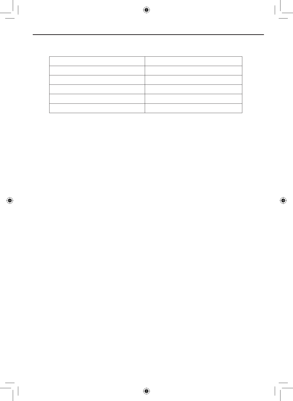
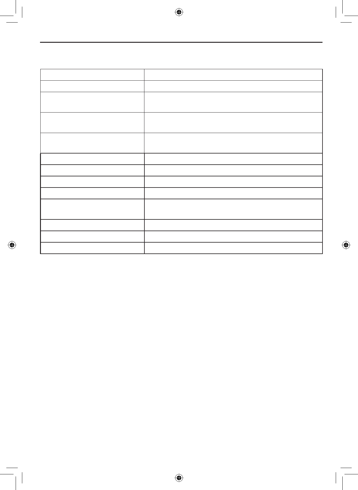
Advanced DSC features
The VHF650 supports the following DSC features:
Feature Menu Item Function
Individual Call Individual Contact another vessel from your directory.
Group Call Group Contact all vessels that share your group
MMSI code.
All Ships Call All Ships Broadcast to all vessels within range (used
for safety or advisory messages.)
Position Request POS Request Request the current location of another
vessel.
Position Send Position Send Transmit your current location to another
vessel.
Name and MMSI
Directory
Directory Store a list of 20 names and MMSI
LGHQWL¿FDWLRQFRGHVIRU'6&FDOOV
Standby Mode Standby Automatically respond to all DSC calls with
an “Unavailable” status.
Received Call Log Receive Log Display the last 10 distress calls received by
the radio and the last 20 general calls.
Using Digital Selective Calling (DSC) Features
Using Digital Selective Calling (DSC) Features
E-26
Getting an MMSI number
In order to use DSC features, you must be assigned an MMSI number and
program that number into your radio. There are two kinds of MMSI numbers:
individual numbers for use by single boats and group numbers for use by
ÀHHWVERDWLQJRUJDQL]DWLRQVHYHQWFRRUGLQDWRUVHWF
You can get more information on MMSI numbers at these resources:
The dealer where you purchased the radio
Recreational boaters can obtain an MMSI number from the Boat
Owner’s Association of the U.S. (http://www.boatus.com/mmsi/ or
call 800-536-1536) or Sea Tow Services International (http://www.
seatow.com/boatingsafety/mmsiinfo.htm)
Commercial boaters need a ship station license to get an MMSI
number. For more information, visit the Federal Communications
Commission (FCC) website at http://wireless.fcc.gov/marine/
fctsht14.html.
•
•
•
Entering MMSI numbers
Individual or user MMSI number
Follow the steps below to enter your individual or user MMSI number into the
radio:
NOTE: Be sure you have the correct User MMSI number before entering it in
the radio. The radio only allows you to enter the user MMSI twice. If you need
to enter the User MMSI number for the third time, contact customer service
(see back page for contact information).
16
User MMSI
Use the up and down
arrows to adjust each of
the nine digits in turn.
0
_______
MENU Setup
SELECT
User MMSI
SELECT
1. Display the menu and choose the Setup sub-menu.
2. Select User MMSI. If an MMSI number was entered previously, the
screen displays it.
E-27
Using Digital Selective Calling (DSC) Features
3. Use the CHANNEL UP and CHANNEL DOWNEXWWRQVWRFKDQJHWKH¿UVWRI
the nine digits; the CHANNEL UP button increases the number and the
CHANNEL DOWN button decreases the number.
:KHQWKH¿UVWGLJLWLVFRUUHFWSUHVVWKHSELECT-1W/25W button. The
FXUVRUPRYHVWRWKHQH[WGLJLW(QWHUWKHUHPDLQLQJHLJKWGLJLWVRIWKH
MMSI number in the same way.
5. When the ninth digit is correct, press the SELECT-1W/25W button. The
UDGLRGLVSOD\VWKHQHZ006,QXPEHUDQGDVNV\RXWRFRQ¿UP
127(%HVXUH\RXHQWHUHGWKHQXPEHUFRUUHFWO\EHIRUHFRQ¿UPLQJWKH
entry. You can only save the user MMSI twice. If the radio displays Cannot
change over 2 times, contact customer service (see back page for contact
information).
6. To save this MMSI number, select Yes. To cancel this MMSI number,
select No. The radio returns to the Setup menu.
Group MMSI number
You can change the group MMSI number as often as you want. Follow the
steps below to enter a group MMSI number into the radio:
16
00
______
Group MMSI
Use the up and down
arrows to adjust the
remaining eight digits.
MENU
Setup
SELECT
Group MMSI
SELECT
1. Display the menu and choose the Setup sub-menu.
2. Select Group MMSI. If a group MMSI number was entered previously,
the screen displays it.
3. Group MMSI numbers always start with a 0, so that digit is already
entered for you. Use the CHANNEL UP and CHANNEL DOWN buttons to
change the second of the nine digits; the CHANNEL UP button increases
the number and the CHANNEL DOWN button decreases the number.
4. When the second digit is correct, press the SELECT-1W/25W button. The
FXUVRUPRYHVWRWKHQH[WGLJLW(QWHUWKHUHPDLQLQJVHYHQGLJLWVRIWKH
MMSI number in the same way.
Using Digital Selective Calling (DSC) Features
E-28
Using the directory
The directory lets you store up to 20 MMSI numbers of other stations so you
can call them quickly.
Follow the steps below to edit the MMSI numbers in your directory:
Use the up & down arrows to
scroll through the alphabet
for each character.
JOHN
123456789
16
MMSI
Name
MENU
DSC Call
SELECT
Directory
SELECT
New
SELECT
5. When the ninth digit is correct, press the SELECT-1W/25W button. The
UDGLRGLVSOD\VWKHQHZ006,QXPEHUDQGDVNV\RXWRFRQ¿UP
6. To save this MMSI number, select Yes. To cancel this MMSI number,
select No. The radio returns to the Setup menu.
1. Display the menu and choose the DSC Call sub-menu.
2. Select Directory. The screen displays any previously-entered MMSI
numbers and names.
3. To add a new MMSI number to the directory, select New.
4. The radio prompts you to enter the nine-digit MMSI number. Use the
CHANNEL UP and CHANNEL DOWNEXWWRQVWRFKDQJHWKH¿UVWGLJLWWKH
CHANNEL UP button increases the number and the CHANNEL DOWN
button decreases the number.
:KHQWKH¿UVWGLJLWLVFRUUHFWSUHVVWKHSELECT-1W/25W button. The
FXUVRUPRYHVWRWKHQH[WGLJLW(QWHUWKHUHPDLQLQJHLJKWGLJLWVRIWKH
MMSI number in the same way.
6. When the ninth digit is correct, press the SELECT-1W/25W button.
7. The radio prompts you to enter a name for this MMSI number; the
name is what you will see in the directory list. Each name can be up
to 12 characters. Use the CHANNEL UP and CHANNEL DOWN buttons
WRFKDQJHWKH¿UVWFKDUDFWHU7KHFKDQQHOEXWWRQVVFUROOWKURXJKWKH
available characters according to the following table:
E-29
Using Digital Selective Calling (DSC) Features
CHANNEL UP button CHANNEL DOWN button
Capital letters (Athrough Z) One blank space
Lower-case letters (athrough z) Numbers (0through 9)
Punctuation (/‘+-) Punctuation (/‘+-)
Numbers (0through 9) Lower-case letters (athrough z)
One blank space Capital letters (Athrough Z)
Table 6 - Character and text entry order
:KHQWKH¿UVWFKDUDFWHULVFRUUHFWSUHVVWKHSELECT-1W/25W button.
7KHFXUVRUPRYHVWRWKHQH[WFKDUDFWHU(QWHUWKHUHPDLQLQJ
characters of the name. If the name is shorter than 12 characters,
press and hold the SELECT-1W/25W button to complete the name entry.
(If you press and hold the SELECT-1W/25W button without entering a
name, the radio uses the MMSI number in the directory list.)
:KHQ\RX¿QLVKHQWHULQJWKHQDPHWKHUDGLRGLVSOD\VWKHQHZ006,
QXPEHUDQGQDPHDQGDVNV\RXWRFRQ¿UP7RVDYHWKLVGLUHFWRU\
entry, select Yes; to cancel this directory entry, select No. The radio
returns to the directory list.
7RFKDQJHDQH[LVWLQJGLUHFWRU\HQWU\VHOHFWWKHHQWU\\RXZDQWWR
change.
11. To delete the directory entry, select Delete. To edit the code, select
Edit, then use CHANNEL UP and CHANNEL DOWN buttons to edit the
MMSI number and the name.
:KHQ\RXDUHVDWLV¿HGZLWKWKHGLUHFWRU\OLVWVHOHFWExit to close the
menu screen.
Using Digital Selective Calling (DSC) Features
E-30
Making DSC Calls
There are essentially four different types of DSC voice calls:
Call type What it does When to use it
Distress Alerts all stations that you need
assistance and sends them your
current position.
In an emergency only.
Individual Calls a single station using the
User MMSI.
Any time you want to talk to
another station.
Group Calls all the stations that have the
same Group MMSI as yours.
Any time you want to talk with
the whole group you are traveling
with at the same time.
All ships Calls all stations in range of your
radio.
Safety warnings (e.g., debris
in the water) or an urgency
situation.
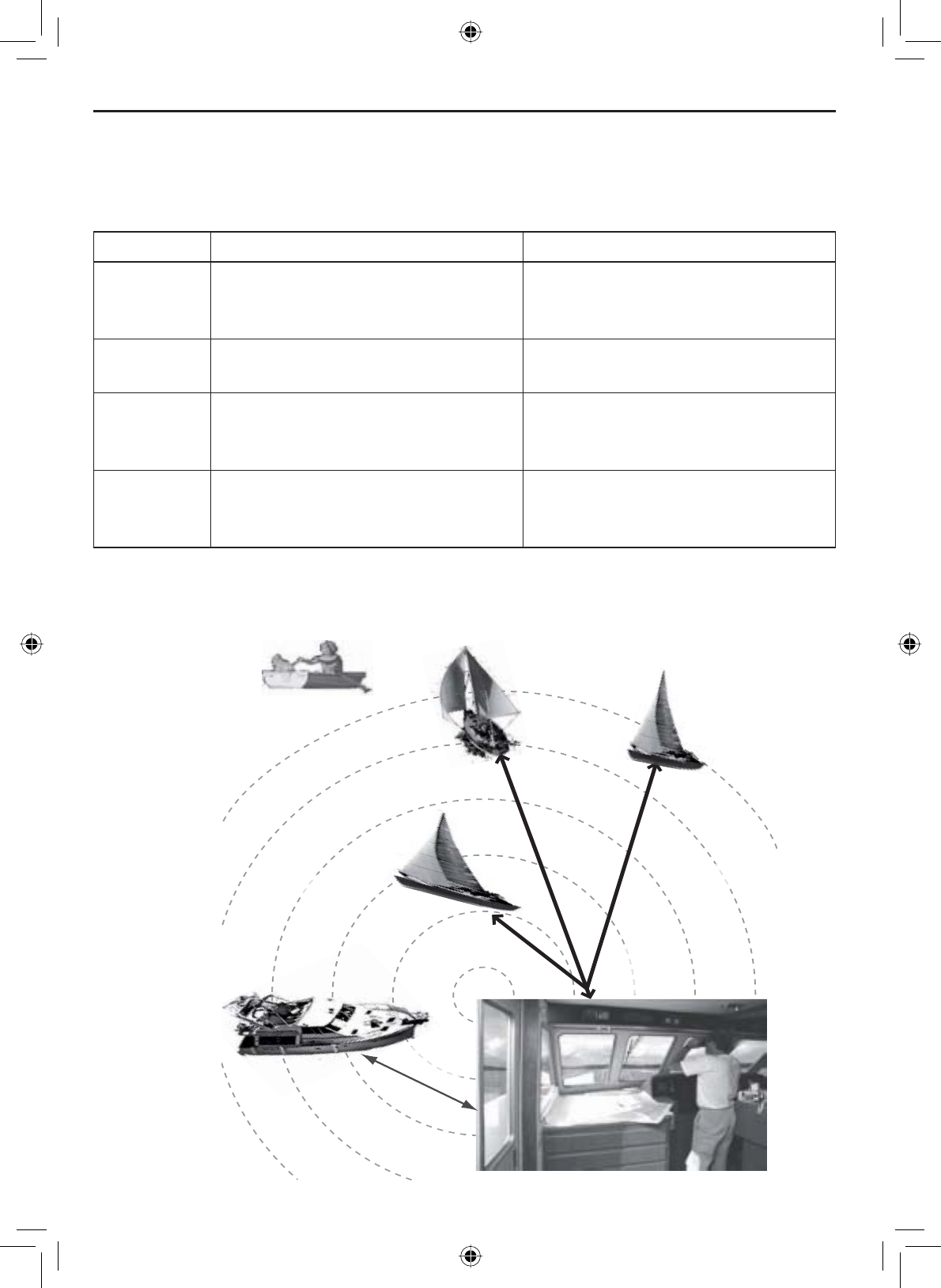
All ships call
Group
call
Individual
call
All ships call
)RUH[DPSOHVRIKRZ\RXPLJKWXVHGLIIHUHQWFDOOW\SHVVHHWKHGLDJUDP
below:

E-31
Using Digital Selective Calling (DSC) Features
Suppose you are coordinating safety for a sailboat race. Before the race
starts, you instruct all the racers to enter your group MMSI number into their
radios. During the race:
• Throughout the race, you use group calling to update the racers on the
time, race status, and any course corrections.
• A power boat full of spectators comes a little too close to the race path.
You use individual calling to contact the power boat and advise them to
stay clear of the race.
• You see a rowboat entering the area, but since it doesn’t have a radio,
you can’t communicate with the rowboat. You use all ships calling to
alert all the other boats in the area of the possible danger.
Calling a single station (Individual Call)
To call a single station with DSC, follow the steps below:
Press the MENU-PA button to display the menu.
Choose the DSC Call sub-menu, then select Individual.
The radio displays the names listed in your directory; use CHANNEL UP
and CHANNEL DOWN buttons to highlight the directory entry you want to
call and press the SELECT-1W/25W button.
If you want to call a station that is not in your directory, select Manual.
The radio prompts you to enter the MMSI number you want to call.
Enter the MMSI number the same way you enter directory entries (see
page 26) Enter all nine digits and press the SELECT-1W/25Wbutton.
The radio prompts you to select a response channel. Use CHANNEL UP
and CHANNEL DOWN buttons to scroll through the available channels.
When you reach the channel you want to use for a response, press the
SELECT-1W/25W button.
The radio displays the MMSI number you are about to call and asks
\RXWRFRQ¿UP,I\RXZDQWWRFDOOWKHGLVSOD\HG006,QXPEHUVHOHFW
Send. To cancel the call, select Cancel.
The radio automatically switches to channel 70 to transmit the call
request.
1.
2.
3.
4.
5.
6.

Using Digital Selective Calling (DSC) Features
E-32
When the other station accepts the call, both radios switch to the se-
lected response channel for voice transmission.
If the other station cannot respond on the channel you selected, the
radio displays Not support CH.
•
•
Calling a particular group of stations (Group Call)
Group calling calls all the stations that share your group MMSI. You must
have a group MMSI programmed into the radio to make a group call, and
the stations (boats) you are calling must have this same group MMSI
programmed into their radios.
Calling all stations (All-Ships Call)
All ships calling contacts all DSC radios within range of your boat. You should
only use all ships calling in the event of a Safety warning (such as debris in
the water) or to request assistance in an Urgency (any situation where your
vessel has a serious problem but is not yet in distress).
Press the MENU-PA button to display the menu.
Choose the DSC Call sub-menu and select All Ships.
7KHUDGLRDVNV\RXWRFRQ¿UPWKHFDOO6HOHFWSend to continue with the
call or select Cancel to cancel the call.
The radio automatically switches to channel 70 to transmit the call
request then automatically switches to channel 16, the designated
response channel for all-ships calling.
1.
2.
3.
4.
Press the MENU-PA button to display the menu.
Choose the DSC Call sub-menu and select Group.
The radio prompts you to select a response channel. Use the CHANNEL
UP and CHANNEL DOWN buttons to scroll through the available channels.
When you reach the channel you want to use for a response, press the
SELECT-1W/25W button.
7KHUDGLRDVNV\RXWRFRQ¿UPWKHFDOO6HOHFWSend to continue with the
call or select Cancel to cancel the call.
The radio switches to channel 70 to transmit the call request then
automatically switches to the designated response channel.
1.
2.
3.
4.
5.

E-33
Using Digital Selective Calling (DSC) Features
Making an automatic distress call
If you have programmed your MMSI number, the VHF650 can transmit an
automated distress call with your current location and nature of the distress.
The radio then monitors the channel 16 for a response and repeats the
distress call every few minutes until it receives an acknowledgement.
To send an automatic distress call, press and hold the DISTRESS button
for three seconds. If no MMSI number has been programmed, the radio
prompts you to enter your MMSI number.
If you want to include the nature of your distress in the distress call, use the
distress procedure below:
1. Press the DISTRESS button.
2. The radio displays the list of distress conditions; use the CHANNEL UP
and CHANNEL DOWN buttons to highlight the nature of your distress,
then press and hold the DISTRESS button for three seconds.
• Undesignated
• Fire
• Flooding
• Collision
• Grounding
• Capsizing
• Sinking
• Adrift
• Abandoning
• Piracy/Armed
• Overboard
3. If no MMSI number has been programmed, the radio prompts you to
enter your MMSI number.
Canceling an automatic distress call
While the radio is waiting for a response, it gives you the option of canceling
the call. To cancel the distress call, highlight Cancel and press the SELECT-
1W/25W button.
Using Digital Selective Calling (DSC) Features
E-34
Receiving a DSC call
If your radio receives an individual DSC call from another station, it sounds
an incoming call tone and displays the name or MMSI number of the station
calling you. To respond to the call, select Send: Able-Comply; the radio sends
an acknowledgement and automatically switches to the designated response
channel. To reject the call, select Send: Unable-Comply; the radio advises the
other station that you are unable to respond to the call.
If the DSC request contains a response channel that you are not allowed to
use, the radio displays Not Support CH; your only response option is Send:
Unable-Comply.
If the radio receives a group or all ships call, it sounds an incoming call tone
and automatically switches to the designated response channel.
Receive log
Just like your telephone’s caller ID list, your radio keeps track of the calls you
receive but do not answer. The receive log is useful if you have been off your
boat or away from your radio and want to see who has tried to contact you.
The radio displays the last 10 distress calls and the last 20 non-distress calls
that it received.
88
A
123456789
987654321
[Exit]
Distress Log
MENU
DSC Call
SELECT
Receive Log
SELECT
Distress
SELECT
Press the MENU-PA button to display the menu.
Choose the DSC Call sub-menu and then select Receive Log.
Select Distress to see the last 10 distress call received by the radio.
Select Other to see the last 20 normal calls received by the radio, then
choose from Individual,Group or All Ships calls.
Calls are listed in the order they were received, with the newest call
VKRZQ¿UVW7KHGLVSOD\EOLQNVLIWKHUHDUHQHZFDOOV\RXKDYHQRW
reviewed.
Select the call you want to see the details of. Use CHANNEL UP and
CHANNEL DOWN buttons to see all of the information. The log displays
different information depending on type of call received. See the table
below for the information stored for each type of call:
1.
2.
3.
4.
5.
E-35
Using Digital Selective Calling (DSC) Features
DSC Call Type Receive Log Information
Distress MMSI (or name), position, time, nature code.
Distress Acknowledge MMSI (or name), distress MMSI, position, time,
nature code.
Distress Relay MMSI (or name), distress MMSI, position, time,
nature code.
Distress Relay Acknowledge MMSI (or name), distress MMSI, position, time,
nature code.
Geographical MMSI (or name), category code.
All Ships MMSI (or name), category code.
Group MMSI (or name), category code.
Individual MMSI (or name), category code.
Individual Acknowledge MMSI (or name), Completed/Unattended, category
code.
Pos Reply MMSI (or name), position, time, category code.
Pos Request MMSI (or name), category code.
Pos Send MMSI (or name), position, time, category code.
6. Press the MENU-PAEXWWRQWRH[LWWKHGHWDLOVFUHHQDQGUHWXUQWRWKHORJ
menu.
7. From the log menu, select Exit to close the receive log and return to
the mode you were in.
Returning a call
You can return individual calls directly from the receive log. From the call
detail screen, press the CHANNEL DOWN button until Call Back appears at the
bottom of the display. Press the SELECT-1W/25W button to return that station's
call.
Requesting another station's position (POS Request)
$Q\WLPH\RXQHHGWRNQRZZKHUHDQRWKHUERDWFXUUHQWO\LV²WR¿QG\RXU
boating partners, to respond to a request for assistance, etc.—you can send
a position request to their radio:
Table 7 - Receive Log
Using Digital Selective Calling (DSC) Features
E-36
Press the MENU-PA button to display the menu.
Choose the DSC Call sub-menu, then select POS Request.
The radio displays the names listed in your directory; use CHANNEL UP
and CHANNEL DOWN buttons to highlight the directory entry you want to
contact and press the SELECT-1W/25W button. If you want to contact a
station that is not in your directory, select Manual. The radio prompts
you to enter the MMSI number you want to call. Enter the MMSI
number the same way you enter directory entries (see page 27). Enter
all nine digits and press the SELECT-1W/25W button.
The radio displays the MMSI number you are about to contact and
DVNV\RXWRFRQ¿UP,I\RXZDQWWRUHTXHVWWKHSRVLWLRQRIWKHGLVSOD\HG
MMSI number, select Send. To cancel the request, select Cancel.
1.
2.
3.
4.
When the other station responds, the radio displays the MMSI number,
the longitude, and the latitude of the other station. If your radio is
connected to a chartplotter through the NMEA OUT connection (see
page 66), the position information will also be displayed on the plotter
screen.
If the other station does not have valid GPS data, the radio displays No
Position.
5.
6.
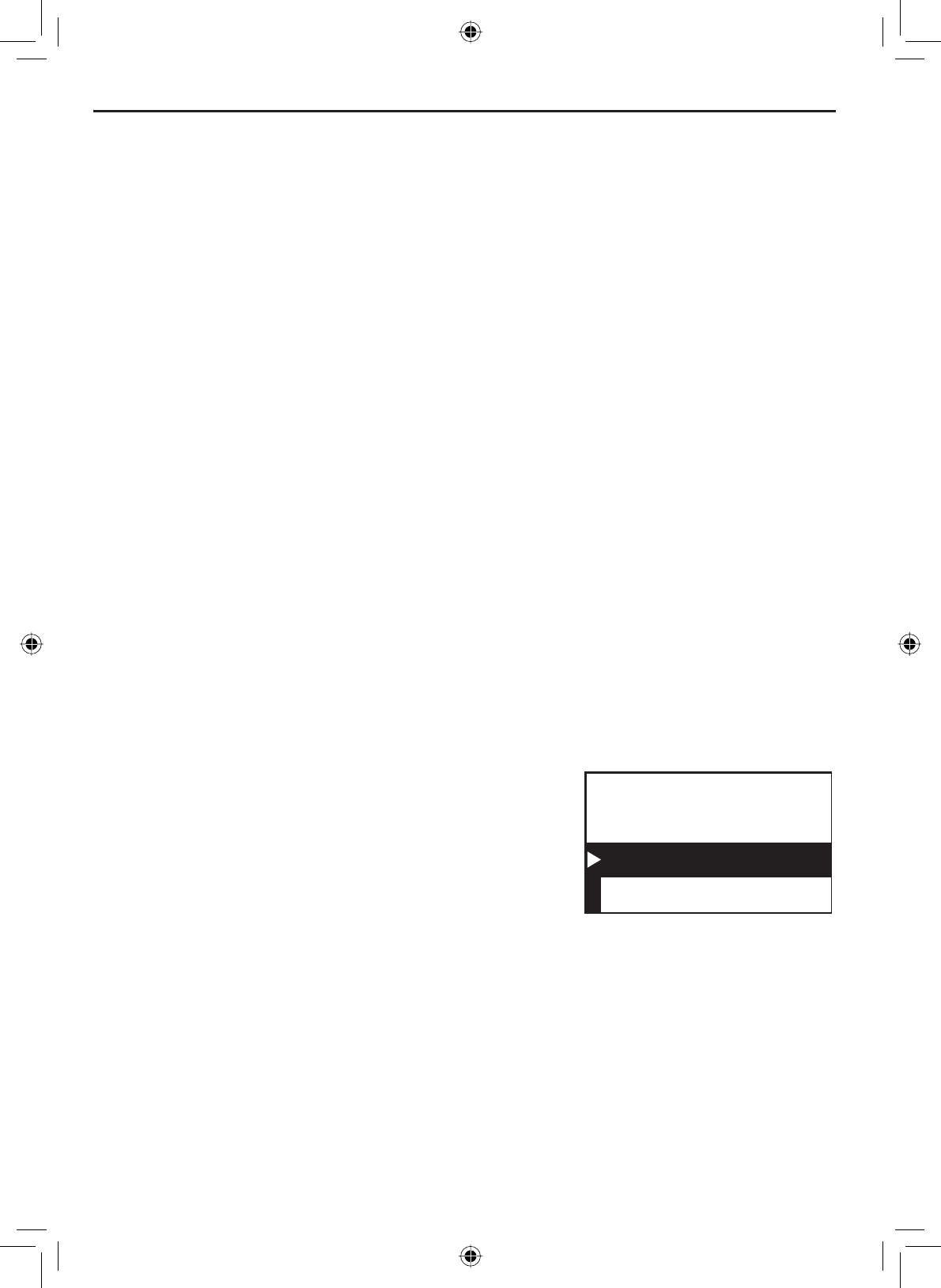
Receiving a position request (Position Reply)
When another station requests your current position, the radio displays the
following screen:
88
A
Reply
Cancel
POS Request
JOHN HENRY
To send your current position to the other
station, select Reply; the radio transmits your
latitude and longitude to the other station. If
you select Reply but the radio does not have
valid GPS data, it transmits the reply code
with No Position.
To reject the position request, select Cancel.
Enabling automatic position reply
If you want the radio to automatically transmit your current position whenever
it receives a position request, you can enable automatic position reply. Most
boaters activate automatic position reply for safety reasons or because they
VXEVFULEHWRDPDULQHWRZLQJVHUYLFH6RPHWLPHV²IRUH[DPSOHLQVRPH
competitive situations--you may not want other stations to get your position
ZLWKRXW\RXUPDQXDOFRQ¿UPDWLRQ

E-37
Using Digital Selective Calling (DSC) Features
Press the MENU-PA button to display the menu.
Select Setup and then POS Reply.
Highlight Auto and press the SELECT-1W/25W button. The radio will
automatically transmit your position when it receives a position request.
To disable automatic position reply, repeat the steps above and select
Manual.
1.
2.
3.
4.
Sending your own position (Position Send)
If your radio is connected to a GPS receiver, you can send your boat’s
position to someone else. If you are requesting assistance or using an all
ships call to give a safety warning, you can send your current position so
other stations know where you are:
Press the MENU-PA button to display the menu.
Choose the DSC Call sub-menu, then select Position Send.
The radio displays the names listed in your directory; use CHANNEL UP
and CHANNEL DOWN buttons to highlight the directory entry you want to
contact and press the SELECT-1W/25W button. If you want to contact a
station that is not in your directory, select Manual. The radio prompts
you to enter the MMSI number you want to call. Enter the MMSI
number the same way you enter directory entries (see page 26). Enter
all nine digits and press the SELECT-1W/25W button.
The radio displays the MMSI number you are about to contact and
DVNV\RXWRFRQ¿UP,I\RXZDQWWRWUDQVPLW\RXUSRVLWLRQWRWKH
displayed MMSI number, select Send. To cancel the transmission,
select Cancel.
The radio transmits your MMSI number, your longitude, and your
latitude to the other station.
1.
2.
3.
4.
5.
Putting the radio into standby
If you are leaving your radio or do not wish to answer any DSC calls, you can
put your radio in standby mode. If your radio receives an individual call, it will
automatically respond with a message that indicates your radio is currently
unattended. Follow the steps below to put your radio in standby:
Using Digital Selective Calling (DSC) Features
E-38
88
Unattended
1 Watt USA
Memory
DSC Standby
MENU DSC Call
SELECT
Standby
SELECT
1. Display the menu and choose the DSC Call sub-menu.
2. Select Standby to place your radio in standby mode. The radio displays
the standby screen, above.
3. To cancel standby and return to the mode your radio was in, press any
button.
Disabling automatic channel switching
If you are involved in a bridge-to-bridge call, you may not want the radio to
automatically switch channels when it receives a DSC call. In cases like this,
you can disable automatic channel switching. If you receive an individual call,
the radio will respond with an unattended code, just as if the radio were in
Standby.
Press the MENU-PA button to display the menu.
Select Setup and then Auto CH SW.
Highlight Off and press the SELECT-1W/25W button. The radio will not
automatically switch channels until you reactivate this feature.
NOTE: Use this feature with caution. Deactivating automatic switching and
then forgetting it can make it hard for you to receive DSC calls.
1.
2.
3.

E-39
Renaming Channels
If you discover that a marine radio channel has a different common name
in your local area, you can change the name of that channel to make it
easier for you to use (see the channel list on page 53 for the default channel
names). To rename a channel, follow the steps below:
Display the menu and choose the Setup sub-menu.
Select Channel Name. The screen displays the list of channels.
Use CHANNEL UP and CHANNEL DOWN buttons to highlight the channel
you want to change and press the SELECT-1W/25W button.
Select Rename to enter a new name for this channel. The radio
prompts you to enter a new name for this channel. Each name can be
up to 12 characters. Use the CHANNEL UP and CHANNEL DOWN buttons
WRFKDQJHWKH¿UVWFKDUDFWHU6HHTable 6 Character and text entry
order on page 29 for the available characters and the order in which
they scroll).
:KHQWKH¿UVWFKDUDFWHULVFRUUHFWSUHVVWKHSELECT-1W/25W button.
7KHFXUVRUPRYHVWRWKHQH[WFKDUDFWHU(QWHUWKHUHPDLQLQJ
characters of the name. If the name is shorter than 12 characters,
press and hold the SELECT-1W/25W button to complete the name entry.
:KHQ\RX¿QLVKHQWHULQJWKHQDPHWKHUDGLRGLVSOD\VWKHQHZFKDQQHO
QDPHDQGDVNV\RXWRFRQ¿UP7RVDYHWKLVQHZFKDQQHOQDPHVHOHFW
Yes; to cancel the change, select No. The radio returns to the channel
list.
To restore a channel back to its original name, select the channel and
choose Default.
:KHQ\RXDUHVDWLV¿HGZLWKWKHFKDQQHOOLVWVHOHFWExit to close the
menu screen.
1.
2.
3.
4.
5.
6.
7.
8.
Renaming Channels
Installing the Hardware
E-40
Mounting the radio
The VHF650 can sit at any angle in the mounting bracket so it can easily
accommodate the best location. First, determine the best place to mount the
UDGLR)RURSWLPXPSHUIRUPDQFH¿QGDORFDWLRQWKDWFDQ
3URSHUO\VXSSRUWWKHZHLJKWRIWKHUDGLRDSSUR[LPDWHO\SRXQGVRU
0.9 kilograms. You may need to use some type of anchor with the
mounting screws to hold the radio, depending on the surface.
• Keep the battery leads as short as possible.
• Keep the antenna lead-in wire as short as possible.
$OORZIUHHDLUÀRZDURXQGWKHKHDWVLQNRQWKHUHDURIWKHUDGLR
• Avoid interference with the ship’s compass.
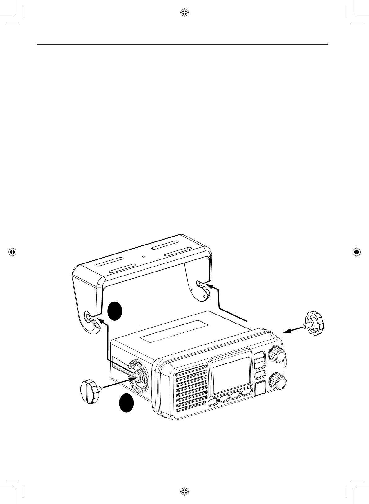
Install the radio into the mounting bracket, and connect the power
cable and accessory cable.
1.
1
2
Step 1:
Slide the radio
into the mounting
bracket.
Step 2:
Tighten the mounting knobs
to secure the radio in place.
Installing the Hardware
E-41
Installing the Hardware
Position the radio into the desired location. Mark the edges of the
bracket on the mounting surface.
Remove the mounting bracket drill template from the back of the
manual, and use the template to mark the drill holes on the mounting
surface.
Drill the holes for the mounting bracket; be sure to follow any special
requirements of the mounting surface.
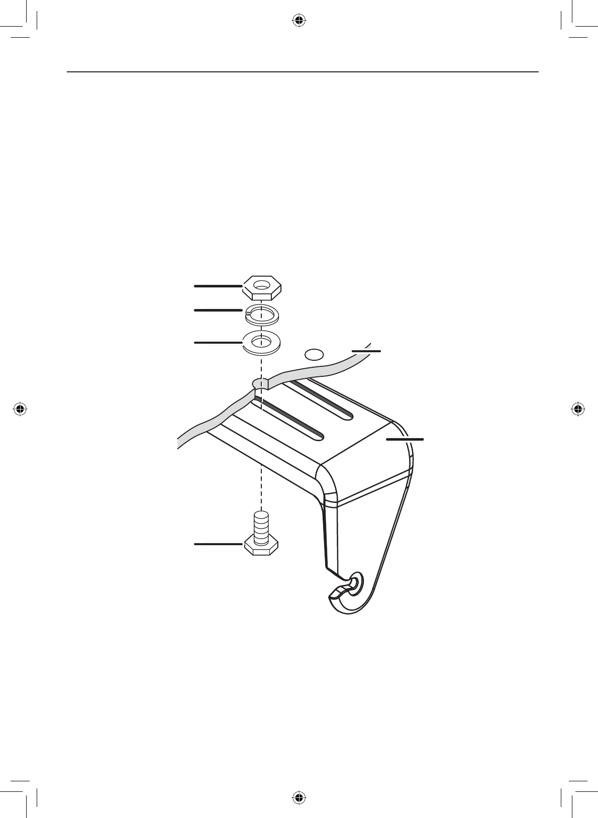
Remove the bracket from the radio, and use the mounting hardware to
secure the bracket to the mounting surface.
2.
3.
4.
5.
Hex bolt
Washer
Spring washer
Hex nut
Mounting
bracket
Mounting
surface
Install the radio back into the mounting bracket.6.
Installing the Hardware
E-42
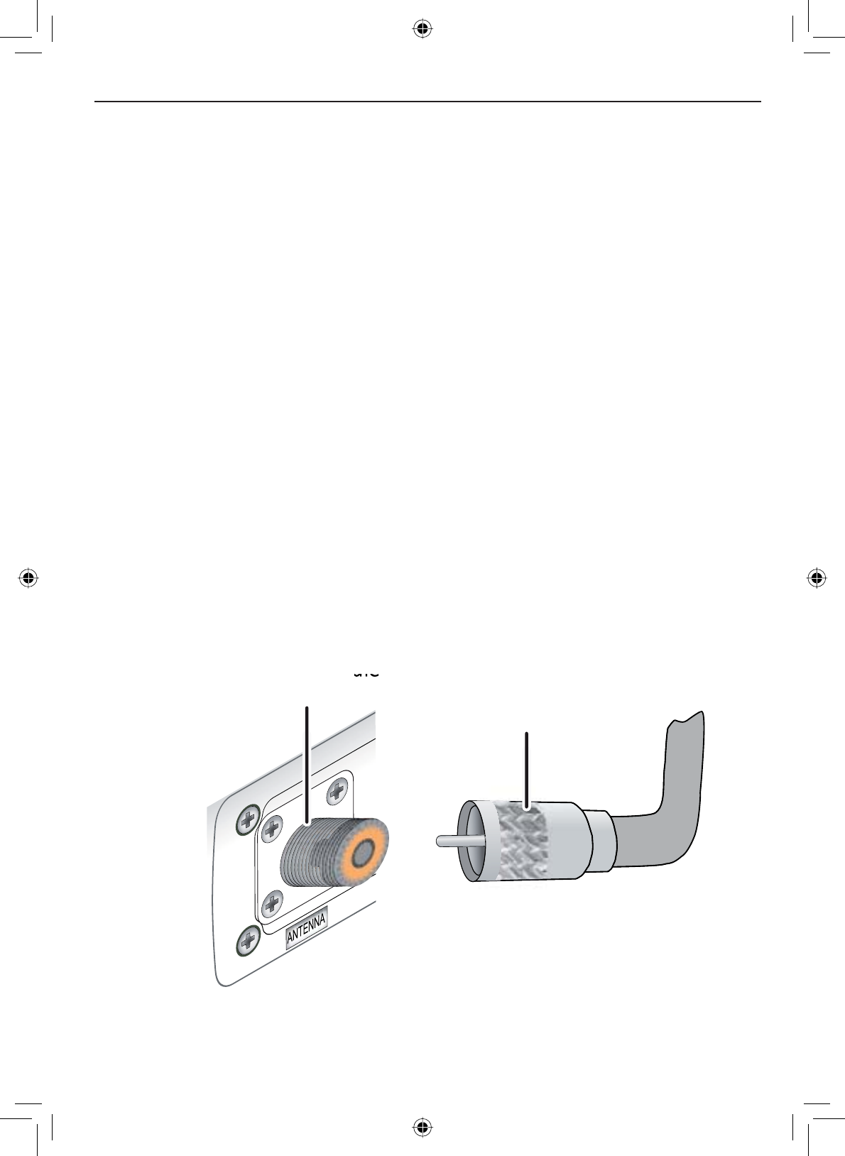
Connecting the radio
To operate correctly, your VHF650 requires two electrical connections:
• providing it with power from the boat’s electrical system
• connecting a VHF-FM marine antenna to the antenna connector
Power supply requirements VHF antenna requirements
Nominal 13.8 VDC power supply with
a negative ground (11.7 VDC to 14.3
VDC).
Power leads should be kept as short
as possible. A direct connection to the
power supply is ideal.
Minimum of #14 AWG copper wire for
H[WHQVLRQVXSWRIHHW$:*ZLUH
IRUH[WHQVLRQVIURPWRIHHWRU
$:*ZLUHIRUH[WHQVLRQVIURPWR
feet.
Male PL-259 connector
LPSHGDQFH
Minimum 4 foot, 3 dB rated antenna for
sailboats or 8 foot, 6dB rated antenna
for powerboats
Minimum RG-58 lead-in wire for antenna
leads up to 20 feet, RG-8X for antenna
leads from 20 to 35 feet, or RG-8U for
antenna leads from 35 to 60 feet.
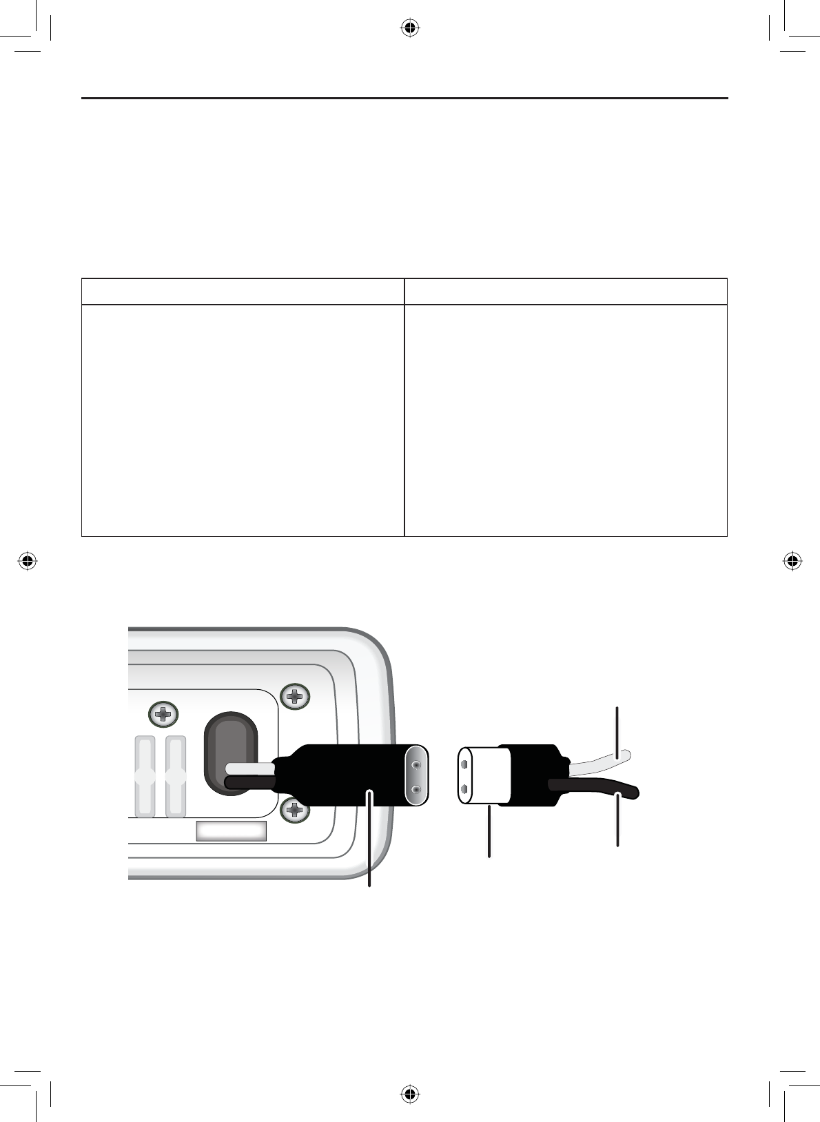
13.8V DC
Power
cable
Power
connector
Black wire
(-)
Red wire
(+)
E-43
Installing the Hardware
Connect the BLACK wire of the included power cable to the
NEGATIVE (-) side of your power source.
Connect the RED wire of the included power cable to the POSITIVE
(+) side of your power source.
Connect the power cable to the power connector on rear of the
9+)7KHSRZHUFRQQHFWRURQO\¿WVRQHZD\
127(7RH[WHQGWKHOLIHRIWKHUDGLRXVHZDWHUSURRIWDSHWRVHDO
electrical connections.
Install your antenna according to the manufacturer’s instructions.
If necessary, consult the FCC guidelines for antenna separation. See
Antenna Selection and Installation on page 67 for more details. (In
summary, the FCC recommends that antennas up to 3 dB be installed
a minimum of 3 feet from any occupied location; antennas over 3 dB
should be installed at least 6 feet away.)
Connect the PL-259 connector from the antenna lead-in wire to the
SO238 connector labeled ANTENNA on the back of the VHF650.
1.
2.
3.
4.
5.
6.
Radio connector,
SO238 (female
PL-259)
SO238 (female
Antenna lead-in
connector,
male PL-259
Installing the Hardware
E-44
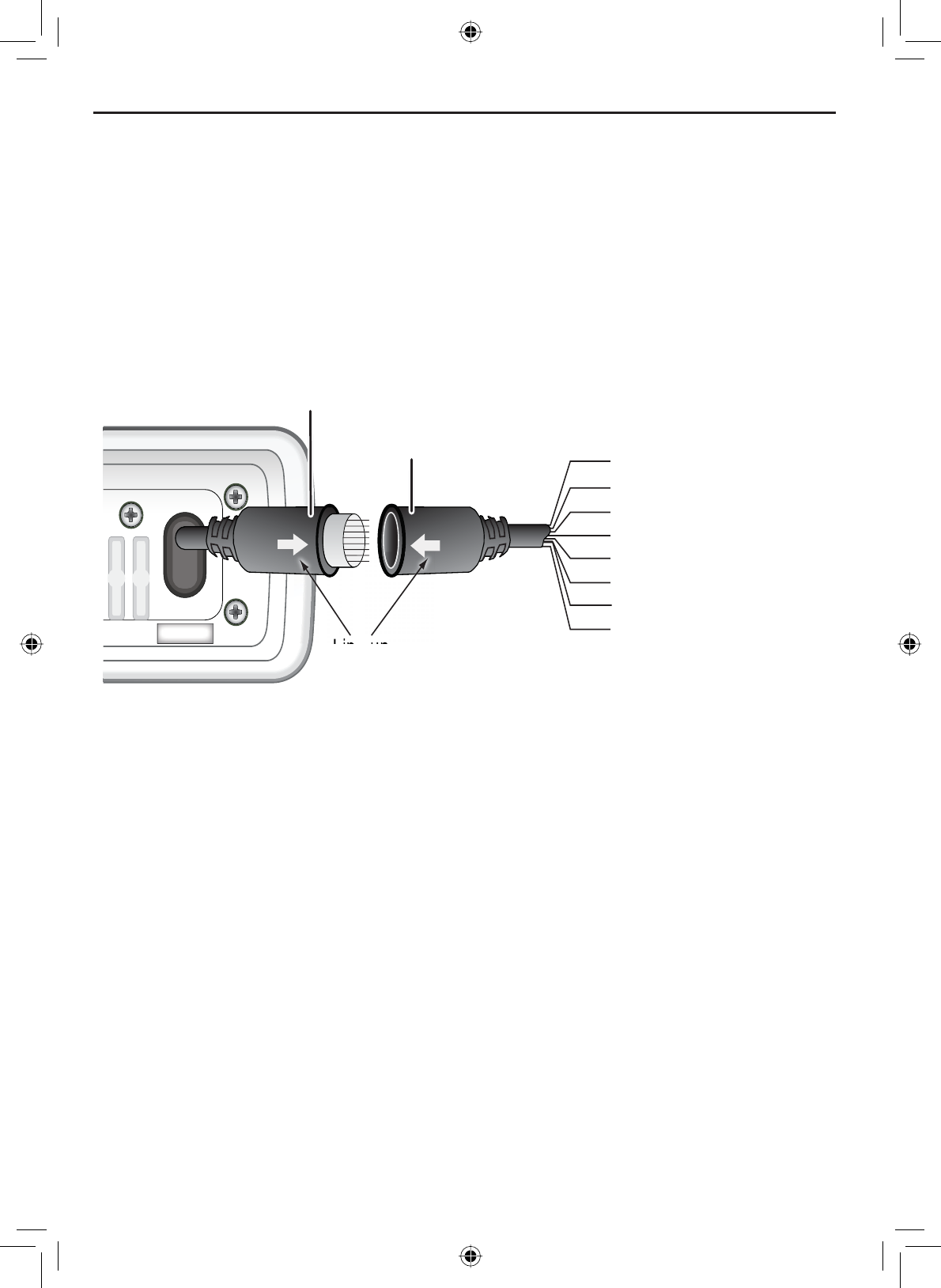
Connecting accessories
Connecting to a GPS receiver
If you connect the radio to a GPS receiver, the radio can automatically
transmit your current position during an automated distress call or during a
normal DSC call.
The VHF650 supports a standard NMEA0183 input from a GPS receiver.
Follow the steps below to connect the VHF650 to your GPS receiver:
13.8V DC
Accessory
cable
Accessory
connector
Green: GPS Data IN (+)
Bare wire: Ground
Black: Ext. Speaker (-)/GND
Red: External Speaker (+)
Brown: PA Speaker (+)
Blue: PA Speaker (-)/ GND
Orange: NMEA OUT (-)
Yellow: NMEA OUT (+)
Line up
arrows to
connect
Line up
Line up
Disconnect the accessory cable from the accessory connection on the
radio.
Connect the BARE wire of the included accessory cable to the
GROUND WIRE on your GPS receiver.
Connect the GREEN wire of the included accessory cable to the
GPS DATA OUTPUT WIRE on your GPS receiver. Below is a table of
common GPS receivers and the proper connections:
1.
2.
3.
E-45
Installing the Hardware
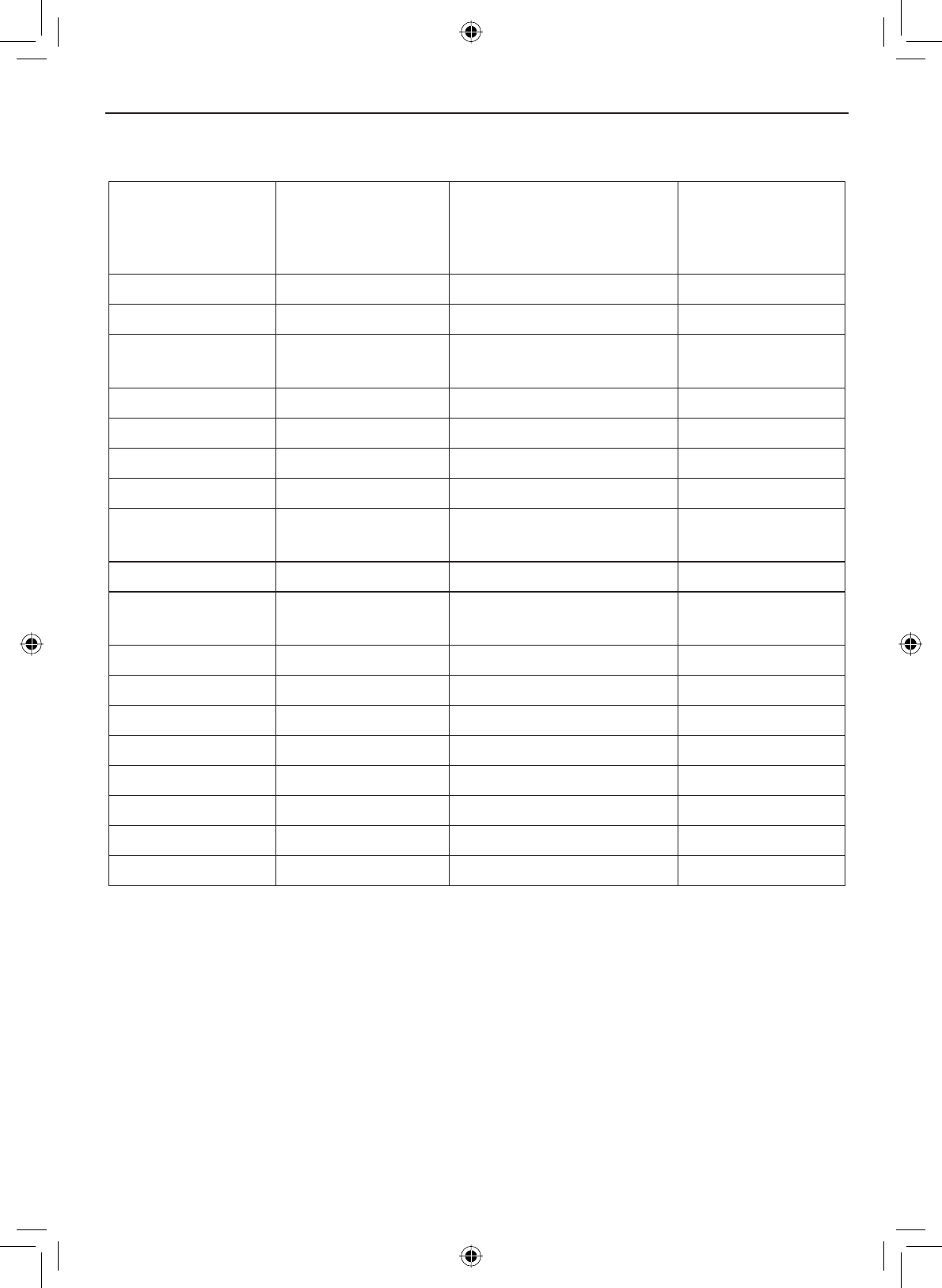
Table 8 - Common GPS receivers and connections
GPS Manufacturer Model Number(s)
GPS NMEA0183 OUTPUT
Wire Color
(Connect to GREEN WIRE
on VHF650)
Ground Wire Color
(connect to BARE
WIRE on VHF650)
Furuno GP1650, GP1850 White Black
Furuno GP30, GP36 White Blue
Garmin )L[HG0RXQW
Models
Blue Black
Garmin Portable Models Brown Black
JRC 100 Series Green Black
JRC 200 Series White Black
JRC GPS500 Yellow Green
Lowrance / Eagle )L[HG0RXQW
Models
White Black
Lowrance / Eagle Portable Models Orange Black
Magellan )L[HG0RXQW
Models
Gray Black
Magellan Portable Models Orange Black
Northstar All Models Yellow Black
RayMarine 420 Yellow Brown
RayMarine 520 / 620 Blue Brown
RayMarine RL Series White Brown
Simrad All Models White Brown
6LWH[ Neptune, Nautilus Gray Brown
Standard CP150 / CP150C Green Yellow
Be certain all wire connections are secure and that all open wires are
adequately covered.
,I\RXDUH¿QLVKHGFRQQHFWLQJDOOH[WHUQDODFFHVVRULHVOLQHXSWKH
arrows on the side of the accessory cable and connector and connect
the accessory cable to the accessory connector on the back on the
VHF650.
127(7RH[WHQGWKHOLIHRIWKHUDGLRXVHZDWHUSURRIWDSHWRVHDO
electrical connections.
4.
5.
Installing the Hardware
E-46
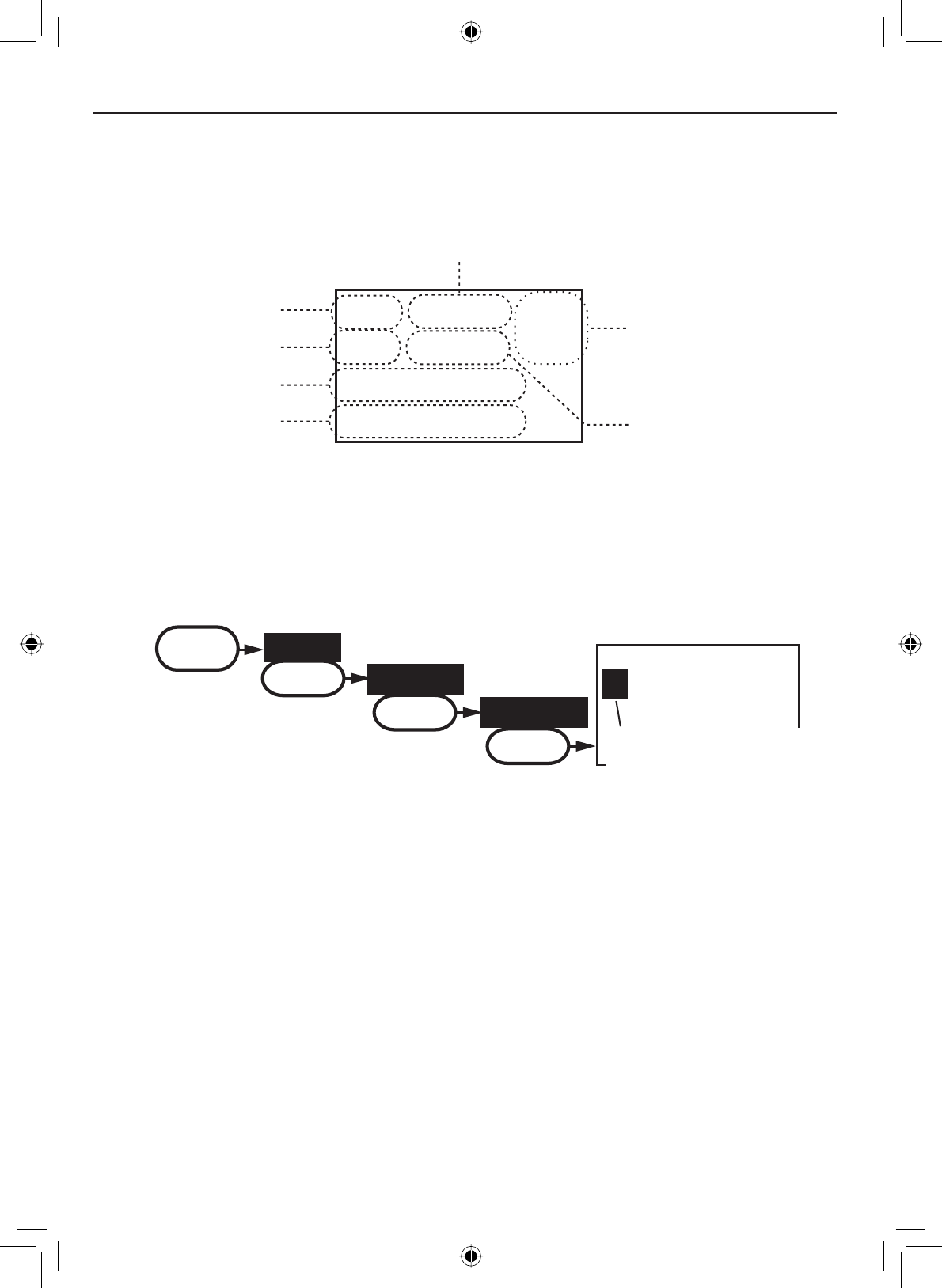
When the GPS receiver is correctly connected, the display shows GPS Data
OK. If there is a problem with the GPS connection, the display shows Check
GPS. When the display shows GPS Data OK, press the SELECT-1W/25W
button to open the GPS status screen and see detailed GPS data:
16
06/20 11:00:00
208
o
30. 0 KT
35
o
40. 610 N
139
o
46. 564 E
Date
Time
Current
channel
Course
Latitude
Longitude Speed
&RQ¿JXULQJWKH*36
If the radio is receiving valid GPS data, it will automatically set the clock to
your local time based on the GPS location. You can adjust your local time
IRUZDUGRUEDFNRQHKRXULIQHFHVVDU\IRUH[DPSOHLI\RXDUHFORVHWRWKH
border of a time zone); you can also adjust for Daylight Savings Time.
Follow the steps below to adjust the time:
Display the menu and choose the Setup sub-menu.
Select GPS Setup and then choose Time Adjust.
The display shows your current local time. To adjust the time forward
one hour, use the CHANNEL UP button. To adjust the time back one hour,
use the CHANNEL DOWN button. Press the SELECT-1W/25W button when
\RXDUH¿QLVKHG
7KHGLVSOD\SURPSWV\RXWRFRQ¿UPWKHVHWWLQJFKRRVHSet to save the
new time or CancelWRH[LW time setup without saving. The radio returns
to the GPS Setup menu.
If your local area observes Daylight Savings Time, highlight Daylight
Save and press the SELECT-1W/25W button.
1.
2.
3.
4.
5.
16
09 : 14
Time Adjust
Use the up or down
arrows to adjust the
time by one hour.
MENU
Setup
SELECT
GPS Setup
SELECT
Time Adjust
SELECT

E-47
Installing the Hardware
Connecting to a charplotter
The VHF650 provides a standard NMEA0183 GPS output that you can
connect to a chartplotter. When it receives another boat’s position data in a
DSC call, the radio sends the position data to the chartplotter so you can see
the location:
If Daylight Savings Time is currently in effect, select On. If Daylight
Savings Time is not currently in effect, select Off.
Press the SELECT-1W/25W button. The radio activates the new time
setting and returns to the GPS Setup menu.
6.
7.
Disconnect the accessory cable from the accessory connection on the
radio.
Connect the ORANGE wire of the accessory cable to the NEGATIVE
(-) wire of your chartplotter’s NMEA data INPUT.
Connect the YELLOW wire of the accessory cable to the POSITIVE
(+) wire of your chartplotter’s NMEA data INPUT
Be certain all wire connections are secure and that all open wires are
adequately covered.
,I\RXDUH¿QLVKHGFRQQHFWLQJDOOH[WHUQDODFFHVVRULHVOLQHXSWKH
arrows on the side of the accessory cable and connector and connect
the accessory cable to the accessory connector on the back on the
VHF650.
127(7RH[WHQGWKHOLIHRIWKHUDGLRXVHZDWHUSURRIWDSHWRVHDO
electrical connections.
1.
2.
3.
4.
5.
Connecting to an external speaker
<RXFDQXVHDQH[WHUQDOVSHDNHUWRPRQLWRUWKHUDGLRIURPDGLIIHUHQWSDUWRI
your boat or in a noisy environment. If you adjust the VOLUME-PWR knob on
WKHUDGLRLWZLOODOVRDGMXVWWKHH[WHUQDOVSHDNHUYROXPH
7KH9+)VXSSRUWVDQH[WHUQDOVSHDNHUZLWKWKHIROORZLQJVSHFL¿FDWLRQV
• Minimum impedance of 4 Ohms
• Minimum power handling of 10 Watts

Installing the Hardware
E-48
Disconnect the accessory cable from the accessory connection on
the radio.
Connect the BLACK wire of the accessory cable to the GROUND
:,5(RI\RXUH[WHUQDOVSHDNHU
Connect the RED wire of the accessory cable to the POSITIVE (+)
:,5(RI\RXUH[WHUQDOVSHDNHU
Be certain all wire connections are secure and that all open wires are
adequately covered.
,I\RXDUH¿QLVKHGFRQQHFWLQJDOOH[WHUQDODFFHVVRULHVOLQHXSWKH
arrows on the side of the accessory cable and connector and connect
the accessory cable to the accessory connector on the back on the
VHF650.
127(7RH[WHQGWKHOLIHRIWKHUDGLRXVHZDWHUSURRIWDSHWRVHDO
electrical connections.
1.
2.
3.
4.
5.
Connecting to an external PA speaker
If you connect the radio to a PA speaker, you can use the PA feature to make
announcements to other boats and people nearby.
7KH9+)VXSSRUWVDQH[WHUQDO3$VSHDNHUZLWKWKHIROORZLQJ
VSHFL¿FDWLRQV
• Minimum impedance of 4 Ohms
• Minimum power handling of 10 Watts
1. Disconnect the accessory cable from the accessory connection on the
radio.
2. Connect the BLUE wire of the accessory cable to the GROUND
WIRE of your PA system.
3. Connect the BROWN wire of the accessory cable to the POSITIVE
(+) WIRE of your PA system.
4. Be certain all wire connections are secure and that all open wires are
adequately covered.
,I\RXDUH¿QLVKHGFRQQHFWLQJDOOH[WHUQDODFFHVVRULHVOLQHXSWKH
arrows on the side of the accessory cable and connector and connect
the accessory cable to the accessory connector on the back on the
VHF650.
127(7RH[WHQGWKHOLIHRIWKHUDGLRXVHZDWHUSURRIWDSHWRVHDO
electrical connections.
E-49
Installing the Hardware
Press and hold the microphone
PUSH TO TALK button. Speak clearly
in your normal voice (you don’t have
to shout). Use the VOLUME-PWR knob
on your VHF650 to adjust the volume of the PA speaker.
Release the PUSH TO TALKEXWWRQZKHQ\RXUH¿QLVKHGWDONLQJ
To turn off the PA feature and return to the radio mode you were using,
press and hold the MENU-PA button for two seconds again.
2.
3.
4.
PA
Public Address
Mode Selected
Using the PA feature
Press and hold the MENU-
PA button for two seconds
to activate the PA feature.
The display shows PA in the
upper right hand corner.
1.

Maintenance and Troubleshooting
E-50
Maintenance and Troubleshooting
Due to its rugged design, the VHF650 requires very little maintenance.
However, it is a precision electronic instrument, so you should follow a few
precautions:
,IWKHDQWHQQDKDVEHHQGDPDJHG\RXVKRXOGQRWWUDQVPLWH[FHSWLQ
the case of an emergency. A defective antenna may cause damage to
your radio.
You are responsible for continued FCC technical compliance of your
radio.
You should arrange for periodic performance checks with your West
Marine dealer.
•
•
•

E-51
Maintenance and Troubleshooting
Problem Things to Try
The radio won’t power on. Check the power connections.
Check the fuse.
Check the master battery switch and
branch circuit that connect to the radio.
The radio won’t transmit. Make sure you are not in weather or
scan mode.
Make sure you are not trying to trans-
mit on a receive-only channel (see the
channels and frequency tables starting
on page 57).
Make sure you are transmitting at the
correct power level for this channel (see
the channels and frequency tables start-
ing on page 57).
Make sure the duration of each trans-
mission is less than 5 minutes.
Noise comes out of the speaker all the
time
Adjust the squelch level; it is probably
too low.
I can’t hear anything (no volume) from
the speaker.
Adjust the squelch level; it is probably
too high.
I can transmit, but no one can hear me. Check your UIC channel settings (see
Setting the UIC channel mode (USA/
CAN/INT) on page 10).
7KHGLVSOD\ÀDVKHVDQG,GRQ¶WNQRZ
why.
7KHGLVSOD\ZLOOÀDVKLIWKHUDGLRLVLQD
watch mode or in scan mode. Try turn-
ing off scanning, Weather Alert Watch,
or Triple/Dual Watch (see pp 14, 15, and
16).
I can’t read the display. Adjust the contrast and backlight bright-
ness level (see page 23)
The display is too bright at night. Adjust the backlight brightness level.
Turn off the radio; hold menu key and
turn it back on (see page 23)
I can’t see any words on the display. Reset the radio back to the default
brightness level: turn off the radio; hold
the menu key and turn it back on.
Common questions
Maintenance and Troubleshooting
E-52
Problem Things to Try
I’m not getting any GPS data on my
display.
Make sure your GPS receiver is
correctly connected (see Connecting to
a GPS receiver).
Make sure your GPS receiver is working
properly.
Make sure that your GPS receiver sup-
ports the NMEA parameters described in
NMEA Operation on page 60.
I’m not getting any hazard alerts. Make sure Weather Alert Watch is
turned on.
Check to make sure the FIPS codes in
your radio include your current loca-
tion (see Using FIPS codes for weather
alerts on page 21).
I’m getting all the hazard alerts, not just
the ones for my area.
Check to make sure the FIPS codes in
your radio were entered correctly (see
Using FIPS codes for weather alerts on
page 21).
Sometimes the Weather Alert Watch
may catch a hazard alert in the middle
of the broadcast and miss which FIPS
codes are affected. For your safety, the
radio triggers the alert tone and switches
to the weather channel when this hap-
pens.
I can’t make Group DSC calls. Make sure the Group MMSI was entered
correctly.
:KHUHFDQ,¿QGP\UDGLR¶VVHULDO
number?
Look on the right side of the radio (the
side with the microphone cord), behind
the mounting bracket.
The radio won’t let me enter my User
MMSI. What do I do?
Contact customer service.

E-53
Maintenance and Troubleshooting
Engine Noise Suppression
Interference from the noise generated by the electrical systems of engines
is sometimes a problem with radios. The VHF650 has been designed to be
essentially impervious to ignition noise and alternator noise. However, in
some installations it may be necessary to take measures to further reduce
the effect of noise interference. The VHF650 radio DC battery wires, antenna
lead, and accessory cables should be routed away from the engine and
engine compartment, and from power cabling carrying high currents. In
severe cases of noise interference, it may be necessary to install a noise
suppression kit. Contact the dealer where you purchased the radio for more
information.
Regulations and Safety Warnings
Maritime radio services operation
Warning! This transmitter will operate on channels/frequencies that have
restricted use in the United States. The channel assignments include
IUHTXHQFLHVDVVLJQHGIRUH[FOXVLYHXVHRIWKH86&RDVW*XDUGXVHLQ
Canada, and use in international waters. Operation on these frequencies
without proper authorization is strictly forbidden. See pages 53 through 58
for a list of available channels and their uses. If you are still not certain which
channels to use, see the FCC maritime radio page at the FCC website (http://
wireless.fcc.gov/marine/) or contact the FCC Call Center at 1-888-CALL-
FCC. For individuals requiring a license, such as commercial users, you
VKRXOGREWDLQDOLFHQVHDSSOLFDWLRQIURP\RXUQHDUHVW)&&¿HOGRI¿FHIRU86
users) or Industry Canada (for Canadian users).
Basic radio guidelines
You should familiarize yourself with the rules on marine radios and be
aware of which rules apply to your boat. Complete guidelines for all ship
and marine radio types can be found at the US Coast Guard website under
the topic Radio Info for Boaters (the direct link is http://www.navcen.uscg.
gov/marcomms/boater.htm). Here are a few guidelines that affect nearly all
boaters.
• If you have a VHF radio on your boat, you must maintain a watch on
channel 16 (156.800 MHz) whenever the radio is not being used to
communicate. Effective from 2004, if a radio is carried, it must be turned
on and set to channel 16 whenever your vessel is underway.
• If you hear a distress call, wait a few minutes to let a shore station or
Coast Guard vessel respond. If no other station has responded after 5
minutes, you must respond to the distress call.
• Do not make false mayday or distress calls as a prank or to test your
radio. (This is essentially like making a false 9-1-1 call; you may be
VXEMHFWWR¿QHV
Specifications
E-54
7DEOH5DGLRVSHFL¿FDWLRQV
$OOVSHFL¿FDWLRQVDUHVXEMHFWWRFKDQJHZLWKRXWQRWLFH
General
Controls VOLUME-PWR, Squelch
Status Indicators Transmit power, Scan mode, Triple Watch mode, Battery
High, Battery low, USA, CAN, INT, Alert, Memory, Weather
band, GPS status and Channel Display
Display /&')XOO'RW0DWUL[
Buttons WX-Alert, 16/9-Tri, Scan-Mem, Channel Up, Channel
Down, Menu-PA, Select-1W/25W, and Distress.
Connectors Antenna, accessory, and DC power
Size +PP[:PP[/PPZLWKRXW+HDW6LQN+
LQFKHV[:LQFKHV[/LQFKHV
Weight 0.9 kg (2 pounds)
Supply Voltage Nominal 13.8V DC, negative ground (11.7 VDC to 14.3
VDC)
Standard Accessories Mounting bracket and hardware, DC power cable,
microphone hanger, spare fuse, accessory cable
Antenna Impedance QRPLQDO
Microphone 5XJJHGNFRQGHQVHUPLFHOHPHQWZLWKFRLOHGFRUG
Speaker LQFK
Operating Temperature Range –20 °C to + 50 °C (–4 °F to +122 °F)
Shock and Vibration 0HHWVRUH[FHHGV(,$VWDQGDUGV56%DQG56&
FCC Approvals Type accepted under part 80 of the Rules; meets Great
Lakes Agreement and party boat requirements
Transmitter
Power Output 1 watt or 25 watt (user selectable)
Power Requirement 25 watts output: 6A@13.8V DC
Modulation ±5 kHz deviation
Hum and Noise Signal-to-Noise 45 dB@1 kHz with 3 kHz deviation with 1000 Hz
modulating frequency (nominal)
Audio Distortion Less than 8% with 3 kHz deviation with 1000 Hz
modulating frequency
Spurious Suppression –25 dBm @ Hi, –25 dBm @ Lo
Output Power Stabilization Built-in automatic level control (ALC)
Frequency Range 156 to 158 MHz
Frequency Stability ±10 ppm @ –20°C to + 50°C
6SHFL¿FDWLRQV
E-55
Specifications
Receiver
Frequency Range 156 to 158 MHz
Sensitivity 0.25 µV for 12 dB SINAD
Circuit Dual Conversion Super Heterodyne PLL (Crystal for DSC)
Squelch Sensitivity 0.2 µV Threshold
Spurious Response 75 dB
Adjacent Channel Selectivity 78 dB @ ±25 kHz
Audio Output Power ZDWWV'LVWRUWLRQORDG
Power Requirement 340 mA @ 13.8V DC at squelched, 860 mA @ 13.8V DC
DWPD[LPXPDXGLRRXWSXW
IF Frequencies 1st 41.925 MHz, 2nd 455 kHz (1st 21.7 MHz, 2nd 455 kHz
for DSC)
Specifications
E-56
Type of Message Appropriate Channel(s)
DISTRESS SAFETY AND CALLING - Use this channel to get the attention
of another station (calling) or in emergencies (distress and safety).
16
INTERSHIP SAFETY - Use this channel for ship-to-ship safety messages
and for search & rescue messages and ships and aircraft of the Coast
Guard.
6
COAST GUARD LIAISON - Use this channel to talk to the Coast Guard
EXW¿UVWPDNHFRQWDFWRQ&KDQQHO
22
NON-COMMERCIAL - Working channels for voluntary boats. Messages
PXVWEHDERXWWKHQHHGVRIWKHVKLS7\SLFDOXVHVLQFOXGH¿VKLQJUHSRUWV
rendezvous, scheduling repairs and berthing information. Use Channels 67
and 72 only for ship-to-ship messages.
96, 68, 69, 71, 72,
78, 794,80
4,67
7.
COMMERCIAL - Working channels for working ships only. Messages must
be about business or the needs of the ship. Use channels 8, 67, 72 and 88
only for ship-to-ship messages.
15,7,8,9,10,11,
18, 19, 635,67
7, 79,
80, 881
PUBLIC CORRESPONDENCE (MARINE OPERATOR) - Use these
channels to call the marine operator at a public coast station. By contacting
a public coast station, you can make and receive calls from telephones on
VKRUH([FHSWIRUGLVWUHVVFDOOVSXEOLFFRDVWVWDWLRQVXVXDOO\FKDUJHIRUWKLV
service.
24, 25, 26, 27, 28,
84, 85, 86, 87, 882
PORT OPERATIONS - These channels are used in directing the movement
of ships in or near ports, locks or waterways. Messages must be about
the operational handling movement and safety of ships. In certain major
ports, Channels 11,12 and are not available for general port operations
messages. Use channel 20 only for ship-to-coast messages. Channel 77 is
limited to intership communications to and from pilots
15,5
3, 12, 14, 20,
635, 65, 66, 73, 74,
77
NAVIGATIONAL - (Also known as the bridge-to-bridge channel.) This
channel is available to all ships. Messages must be about ship navigation,
IRUH[DPSOHSDVVLQJRUPHHWLQJRWKHUVKLSV<RXPXVWNHHS\RXUPHVVDJ-
es short. Your power output must not be more than one watt. This is also
the main working channel at most locks and drawbridges.
13, 67
MARITIME CONTROL - This channel may be used to talk to ships and
coast stations operated by state or local governments. Messages must
pertain to regulation and control, boating activities, or assistance to ships.
17
DIGITAL SELECTIVE CALLING - Use this channel for distress and safety
calling and for general purpose calling using only DSC techniques.
70
WEATHER - On these channels you may receive weather broadcasts of
the National Oceanic and Atmospheric Administration. These channels are
only for receiving. You cannot transmit on them.
:[
:[
:[
Notes:
Not available in the Great Lakes, St. Lawrence Seaway, or the Puget Sound and the Strait of Juan de
Fuca and its approaches.
Only for use In the Great Lakes, St Lawrence Seaway, and Puget Sound and the Strait of Juan de
Fuca and its approaches.
Available only In the Houston and New Orleans areas.
Available only in the Great Lakes.
Available only In the New Orleans area.
Available for Intership, ship, and coast general purpose calling by noncommercial ships.
Available only In the Puget Sound and the Strait of Juan de Fuca.
1.
2.
3.
4.
5.
6.
7.
Channel and frequencies
Table 10 - Channel by type of message

E-57
Specifications
Channel and frequencies
Table 11 - USA Channel Frequencies and Channel Tag
Ch No. RX Freq (MHz) TX Freq (MHz) Status Full Name
1 “A” 156.0500 156.0500 6LPSOH[ 9HVVHOWUDI¿FV\VWHP
Commercial
3 “A” 156.1500 156.1500 6LPSOH[ Coast guard, Govt only
5 “A” 156.2500 156.2500 6LPSOH[ 9HVVHOWUDI¿FV\VWHP
Commercial
6 156.3000 156.3000 6LPSOH[ Inter-ship safety
7 “A” 156.3500 156.3500 6LPSOH[ Commercial
8 156.4000 156.4000 6LPSOH[ Commercial
9 156.4500 156.4500 6LPSOH[ Non commercial
10 156.5000 156.5000 6LPSOH[ Commercial
11 156.5500 156.5500 6LPSOH[ 9HVVHOWUDI¿FV\VWHP
12 156.6000 156.6000 6LPSOH[ 9HVVHOWUDI¿FV\VWHP
13 156.6500 156.6500 6LPSOH[: Bridge to bridge
14 156.7000 156.7000 6LPSOH[ 9HVVHOWUDI¿FV\VWHP
15 156.7500 Inhibit Receive Only Environmental
16 156.8000 156.8000 6LPSOH[ Distress, Safety, Calling
17 156.8500 156.8500 6LPSOH[: Govt maritime control
18 “A” 156.9000 156.9000 6LPSOH[ Commercial
19 “A” 156.9500 156.9500 6LPSOH[ Commercial
20 161.6000 157.0000 'XSOH[ Port operation
20 “A” 157.0000 157.0000 6LPSOH[ Port operation
21 “A” 157.0500 157.0500 6LPSOH[ Coast guard only
22 “A” 157.1000 157.1000 6LPSOH[ Coast guard
23 “A” 157.1500 157.1500 6LPSOH[ Coast guard only
24 161.8000 157.2000 'XSOH[ Marine operator
25 161.8500 157.2500 'XSOH[ Marine operator
26 161.9000 157.3000 'XSOH[ Marine operator
27 161.9500 157.3500 'XSOH[ Marine operator
28 162.0000 157.4000 'XSOH[ Marine operator
61 “A” 156.0750 156.0750 6LPSOH[ Coast guard
63 “A” 156.1750 156.1750 6LPSOH[ 9HVVHOWUDI¿FV\VWHP
64 “A” 156.2250 156.2250 6LPSOH[ Commercial
65 “A” 156.2750 156.2750 6LPSOH[ Port operation
66 “A” 156.3250 156.3250 6LPSOH[ Port operation
67 156.3750 156.3750 6LPSOH[: Bridge to bridge
68 156.4250 156.4250 6LPSOH[ Non commercial
69 156.4750 156.4750 6LPSOH[ Non commercial
70 ( 156.5250 156.5250 ) DSC Only DSC
Specifications
E-58
Table 11 - USA Channel Frequencies and Channel Tag (cont'd)
7KH$LQGLFDWHVVLPSOH[XVHRIWKHVKLSVWDWLRQWUDQVPLWVLGHRIDQLQWHUQDWLRQDOGXSOH[FKDQQHODQGWKDWRSHUDWLRQVDUHGLIIHUHQWIURPWKDWRI
international operations on that channel.
Ch No. RX Freq (MHz) TX Freq (MHz) Status Full Name
71 156.5750 156.5750 6LPSOH[ Non commercial
72 156.6250 156.6250 6LPSOH[ Non commercial (ship-
ship)
73 156.6750 156.6750 6LPSOH[ Port operation
74 156.7250 156.7250 6LPSOH[ Port operation
75 156.775 156.7750 6LPSOH[: Port operation
76 156.825 156.8250 6LPSOH[: Port operation
77 156.8750 156.8750 6LPSOH[: Port operation (ship-ship)
78 “A” 156.9250 156.9250 6LPSOH[ Non commercial
79 “A” 156.9750 156.9750 6LPSOH[ Commercial
80 “A” 157.0250 157.0250 6LPSOH[ Commercial
81 “A” 157.0750 157.0750 6LPSOH[ Coast guard
82 “A” 157.1250 157.1250 6LPSOH[ Coast guard
83 “A” 157.1750 157.1750 6LPSOH[ Government
84 161.8250 157.2250 'XSOH[ Marine operator
85 161.8750 157.2750 'XSOH[ Marine operator
86 161.9250 157.3250 'XSOH[ Marine operator
87 161.9750 157.3750 'XSOH[ Marine operator
88 162.0250 157.4250 'XSOH[ Marine operator
88 “A” 157.4250 157.4250 6LPSOH[ Commercial (ship-ship)

E-59
Specifications
Table 12 - Canadian Channel Frequencies and Channel Tag
Ch No. RX Freq TX Freq Status Full Name
1 160.6500 156.0500 'XSOH[ Marine operator
2 160.7000 156.1000 'XSOH[ Marine operator
3 160.7500 156.1500 'XSOH[ Marine operator
4 “A” 156.2000 156.2000 6LPSOH[ Canadian coast guard
5 “A” 156.2500 156.2500 6LPSOH[ 9HVVHOWUDI¿FV\VWHP
6 156.3000 156.3000 6LPSOH[ Inter-ship safety
7 “A” 156.3500 156.3500 6LPSOH[ Commercial
8 156.4000 156.4000 6LPSOH[ Commercial
9 156.4500 156.4500 6LPSOH[ Boater calling channel
10 156.5000 156.5000 6LPSOH[ Commercial
11 156.5500 156.5500 6LPSOH[ 9HVVHOWUDI¿FV\VWHP
12 156.6000 156.6000 6LPSOH[ 9HVVHOWUDI¿FV\VWHP
13 156.6500 156.6500 6LPSOH[: Bridge to bridge
14 156.7000 156.7000 6LPSOH[ 9HVVHOWUDI¿FV\VWHP
15 156.7500 156.7500 6LPSOH[ Environmental
16 156.8000 156.8000 6LPSOH[ Distress, Safety, Calling
17 156.8500 156.8500 6LPSOH[: State control
18 “A” 156.9000 156.9000 6LPSOH[ Commercial
19 “A” 156.9500 156.9500 6LPSOH[ Canadian coast guard
20 161.6000 157.0000 'XSOH[: Port operation
21 “A” 157.0500 157.0500 6LPSOH[ Canadian coast guard
22 “A” 157.1000 157.1000 6LPSOH[ Canadian coast guard
23 161.7500 157.1500 'XSOH[ Canadian coast guard
24 161.8000 157.2000 'XSOH[ Marine operator
25 161.8500 157.2500 'XSOH[ Marine operator
26 161.9000 157.3000 'XSOH[ Marine operator
27 161.9500 157.3500 'XSOH[ Marine operator
28 162.0000 157.4000 'XSOH[ Marine operator
60 160.6250 156.0250 'XSOH[ Marine operator
61 “A” 156.0750 156.0750 6LPSOH[ Canadian coast guard
62 “A” 156.1250 156.1250 6LPSOH[ Canadian coast guard
64 160.8250 156.2250 'XSOH[ Marine operator
64 “A” 156.2250 156.2250 6LPSOH[ Marine operator
65 “A” 156.2750 156.2750 6LPSOH[ Search and rescue
66 “A” 156.3250 156.3250 6LPSOH[: Port operation
67 156.3750 156.3750 6LPSOH[ Bridge to bridge
68 156.4250 156.4250 6LPSOH[ Non commercial
69 156.4750 156.4750 6LPSOH[ Non commercial
70 ( 156.5250 156.5250 ) DSC Only DSC
71 156.5750 156.5750 6LPSOH[ Non commercial
Specifications
E-60
Ch No. RX Freq TX Freq Status Full Name
72 156.6250 156.6250 6LPSOH[ Non commercial
73 156.6750 156.6750 6LPSOH[ Port operation
74 156.7250 156.7250 6LPSOH[ Port operation
75 156.7750 156.7750 6LPSOH[: Port operation
76 156.8250 156.8250 6LPSOH[: Port operation
77 156.8750 156.8750 6LPSOH[: Port operation
78 “A” 156.9250 156.9250 6LPSOH[ Inter ship
79 “A” 156.9750 156.9750 6LPSOH[ Inter ship
80 “A” 157.0250 157.0250 6LPSOH[ Inter ship
81 “A” 157.0750 157.0750 6LPSOH[ Canadian coast guard
82 “A” 157.1250 157.1250 6LPSOH[ Canadian coast guard
83 161.7750 157.1750 'XSOH[ Canadian coast guard
83 “A” 157.1750 157.1750 6LPSOH[ Canadian coast guard
84 161.8250 157.2250 'XSOH[ Marine operator
85 161.8750 157.2750 'XSOH[ Marine operator
86 161.9250 157.3250 'XSOH[ Marine operator
87 161.9750 157.3750 'XSOH[ Marine operator
88 162.0250 157.4250 'XSOH[ Marine operator
7KH$LQGLFDWHVVLPSOH[XVHRIWKHVKLSVWDWLRQWUDQVPLWVLGHRIDQLQWHUQDWLRQDOGXSOH[FKDQQHODQGWKDWRSHUDWLRQVDUHGLIIHUHQWIURPWKDWRI
international operations on that channel.
Table 12 - Canadian Channel Frequencies and Channel Tag (cont'd)

E-61
Specifications
)
Table 13 - International Channel Frequencies and Channel Tag
Ch No. RX Freq TX Freq Status Full Name
1 160.6500 156.0500 'XSOH[ Marine operator
2 160.7000 156.1000 'XSOH[ Marine operator
3 160.7500 156.1500 'XSOH[ Marine operator
4 160.8000 156.2000 'XSOH[ Marine operator
5 160.8500 156.2500 'XSOH[ Marine operator
6 156.3000 156.3000 6LPSOH[ Inter-ship safety
7 160.9500 156.3500 'XSOH[ Marine operator
8 156.4000 156.4000 6LPSOH[ Commercial (ship-ship)
9 156.4500 156.4500 6LPSOH[ Boater calling channel
10 156.5000 156.5000 6LPSOH[ Commercial
11 156.5500 156.5500 6LPSOH[ 9HVVHOWUDI¿FV\VWHP
12 156.6000 156.6000 6LPSOH[ 9HVVHOWUDI¿FV\VWHP
13 156.6500 156.6500 6LPSOH[ Bridge to bridge
14 156.7000 156.7000 6LPSOH[ 9HVVHOWUDI¿FV\VWHP
15 156.7500 156.7500 6LPSOH[: Environmental
16 156.8000 156.8000 6LPSOH[ Distress, Safety, Calling
17 156.8500 156.8500 6LPSOH[: Govt maritime control
18 161.5000 156.9000 'XSOH[ Port operation
19 161.5500 156.9500 'XSOH[ Commercial
20 161.6000 157.0000 'XSOH[ Port operation
21 161.6500 157.0500 'XSOH[ Port operation
22 161.7000 157.1000 'XSOH[ Port operation
23 161.7500 157.1500 'XSOH[ Marine operator
24 161.8000 157.2000 'XSOH[ Marine operator
25 161.8500 157.2500 'XSOH[ Marine operator
26 161.9000 157.3000 'XSOH[ Marine operator
27 161.9500 157.3500 'XSOH[ Marine operator
28 162.0000 157.4000 'XSOH[ Marine operator
60 160.6250 156.0250 'XSOH[ Marine operator
61 160.6750 156.0750 'XSOH[ Marine operator
62 160.7250 156.1250 'XSOH[ Marine operator
63 160.7750 156.1750 'XSOH[ Marine operator
64 160.8250 156.2250 'XSOH[ Marine operator
65 160.8750 156.2750 'XSOH[ Marine operator
66 160.9250 156.3250 'XSOH[ Marine operator
67 156.3750 156.3750 6LPSOH[ Bridge to bridge
68 156.4250 156.4250 6LPSOH[ Non commercial
69 156.4750 156.4750 6LPSOH[ Non commercial
70 ( 156.5250 156.5250 ) DSC Only DSC
71 156.5750 156.5750 6LPSOH[ Non commercial
Specifications
E-62
Ch No. RX Freq TX Freq Status Full Name
72 156.6250 156.6250 6LPSOH[ Non commercial
73 156.6750 156.6750 6LPSOH[ Port operation
74 156.7250 156.7250 6LPSOH[ Port operation
75 156.7750 156.7750 6LPSOH[: Port operation
76 156.8250 156.8250 6LPSOH[: Port operation
77 156.8750 156.8750 6LPSOH[ Port operation (ship-ship)
78 161.5250 156.9250 'XSOH[ Port operation
79 161.5750 156.9750 'XSOH[ Port operation
80 161.6250 157.0250 'XSOH[ Port operation
81 161.6750 157.0750 'XSOH[ Port operation
82 161.7250 157.1250 'XSOH[ Port operation
83 161.7750 157.1750 'XSOH[ Port operation
84 161.8250 157.2250 'XSOH[ Marine operator
85 161.8750 157.2750 'XSOH[ Marine operator
86 161.9250 157.3250 'XSOH[ Marine operator
87 161.9750 157.3750 'XSOH[ Marine operator
88 162.0250 157.4250 'XSOH[ Marine operator
7KH$LQGLFDWHVVLPSOH[XVHRIWKHVKLSVWDWLRQWUDQVPLWVLGHRIDQLQWHUQDWLRQDOGXSOH[FKDQQHODQGWKDWRSHUDWLRQVDUHGLIIHUHQWIURPWKDWRI
international operations on that channel.
Table 13 - International Channel Frequencies and Channel Tag
(cont'd)
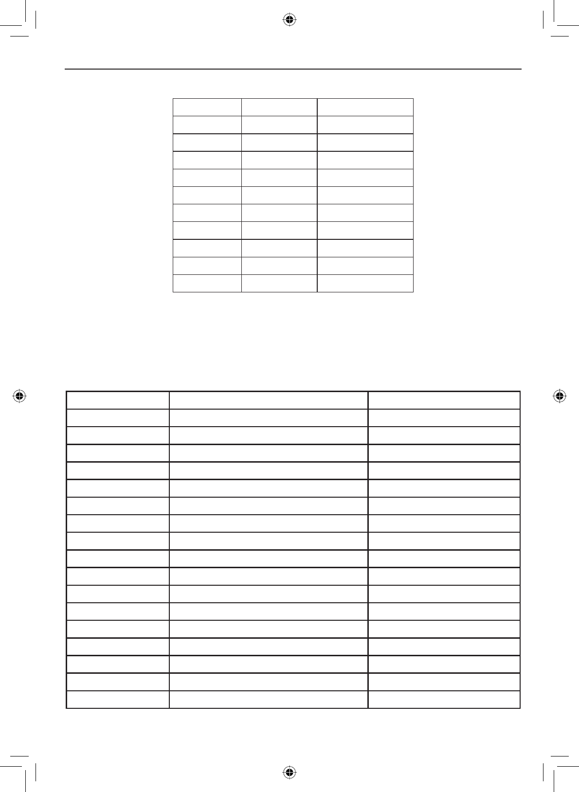
E-63
Specifications
Table 14 - Weather Channel Frequencies
Ch No. RX Freq Channel Name
WX01 162.5500 162.550 MHz
WX02 162.4000 162.400 MHz
WX03 162.4750 162.475 MHz
WX04 162.4250 162.425 MHz
WX05 162.4500 162.450 MHz
WX06 162.5000 162.500 MHz
WX07 162.5250 162.525 MHz
WX08 161.6500 161.650 MHz
WX09 161.7750 161.775 MHz
WX10 163.2750 163.275 MHz
(Common to each mode of USA, INTERNATIONAL and CANADA)
Table 15 - CEA2009-S.A.M.E. Event Code
Alert codes and event levels
Standard Event Code (LCD Display) Event Level
ADR Administrative Message Statement
AVA Avalanche Watch Watch
AVW Avalanche Warning WARNING
BHW Biological Hazard Warning WARNING
BWW Boil Water Warning WARNING
BZW Blizzard Warning WARNING
CAE Child Abduction Emergency Statement
CDW Civil Danger Warning WARNING
CEM Civil Emergency Message WARNING
CFA Coastal Flood Watch Watch
CFW Coastal Flood Warning WARNING
CHW Chemical Hazard Warning WARNING
DBA Dam Watch Test
DBW Dam Break Warning WARNING
DEW Contagious Disease Warning WARNING
DMO Practice/Demo Statement
DSW Dust Storm Warning WARNING
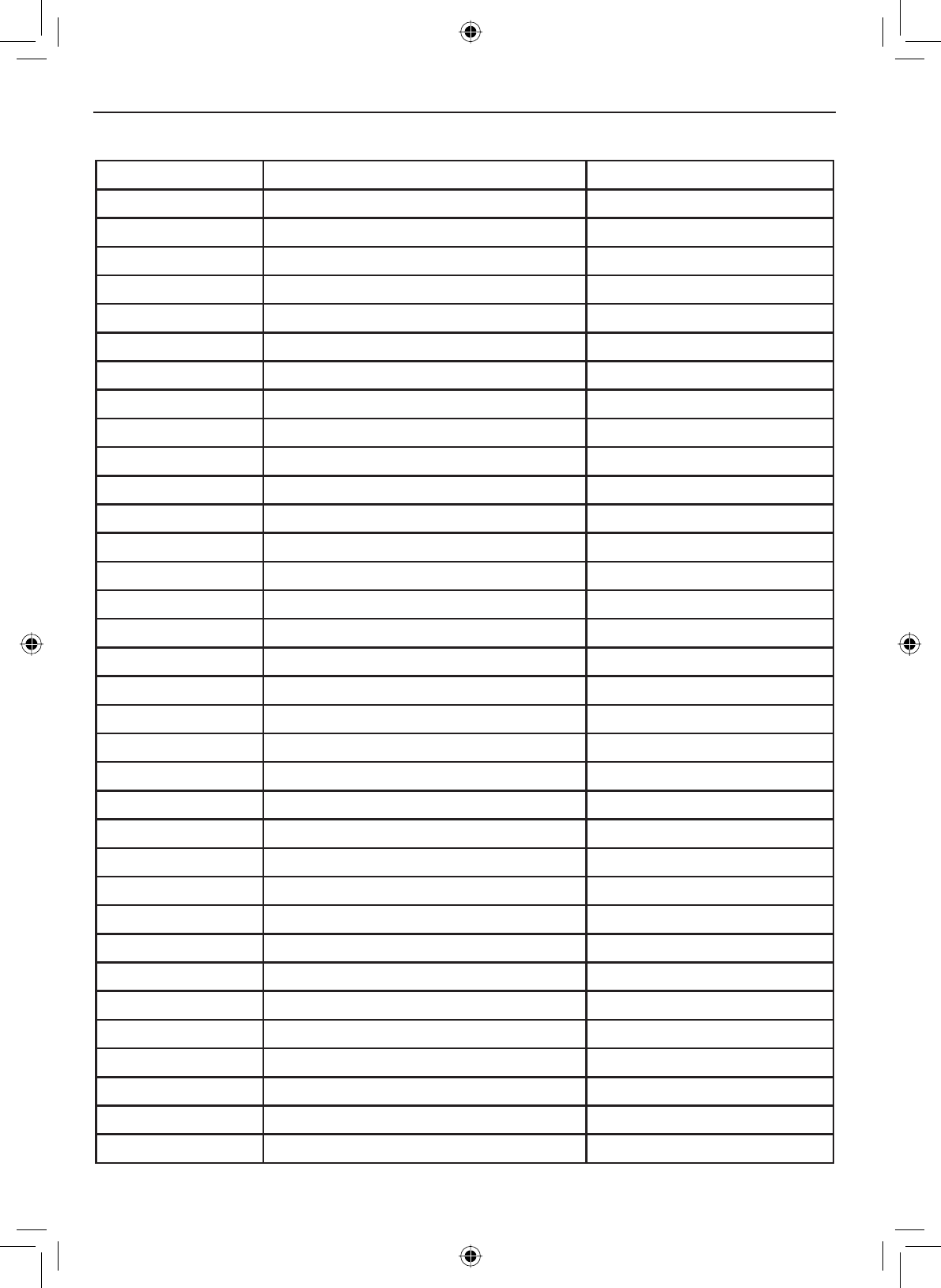
Specifications
E-64
Standard Event Code (LCD Display) Event Level
EAN (PHUJHQF\$FWLRQ1RWL¿FDWLRQ WARNING
EAT Emergency Action Termination Statement
EQW Earthquake Warning WARNING
EVI Immediate Evacuation WARNING
EVA Evacuation Watch Watch
FCW Food Contamination Warning WARNING
FFA Flash Flood Watch Watch
FFS Flash Flood Statement Statement
FFW Flash Flood Warning WARNING
FLA Flood Watch Watch
FLS Flood Statement Statement
FLW Flood Warning WARNING
FRW Fire Warning WARNING
FSW Flash Freeze Warning WARNING
FZW Freeze Warning WARNING
HLS Hurricane Statement Statement
HMW Hazardous Material Warning WARNING
HUA Hurricane Watch Watch
HUW Hurricane Warning WARNING
HWA High Wind Watch Watch
HWW High Wind Warning WARNING
IBW Iceberg Warning WARNING
IFW Industrial Fire Warning WARNING
LAE Local Area Emergency Statement
LEW Law Enforcement Warning WARNING
LSW Land Slide Warning WARNING
NAT National Audible Test Test
NIC National Information Center Statement
NMN 1HWZRUN1RWL¿FDWLRQ0HVVDJH Statement
NPT National Periodic Test Test
NST National Silent Test Test
NUW Nuclear Power Plant Warning WARNING
POS Power Outage Advisory Statement
RHW Radiological Hazard Warning WARNING
Table 15 - CEA2009-S.A.M.E. Event Code (cont'd)
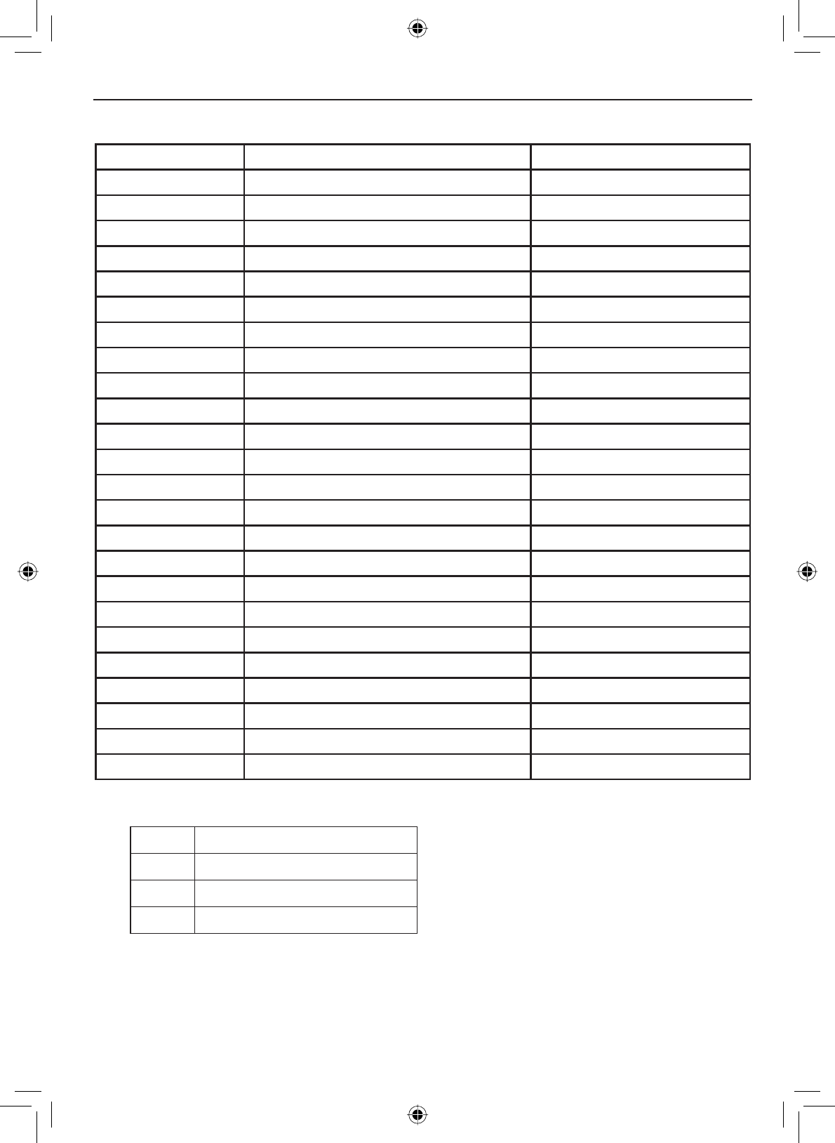
E-65
Specifications
Standard Event Code (LCD Display) Event Level
RMT Required Monthly Test Test
RWT Required Weekly Test Test
SMW Special Marine Warning WARNING
SPS Special Weather Statement Statement
SPW Shelter In-Place Warning WARNING
SVA Severe Thunderstorm Watch Watch
SVR Severe Thunderstorm Warning WARNING
SVS Severe Weather Statement Statement
TOA Tornado Watch Watch
TOE 911 Telephone Outage Emergency Statement
TOR Tornado Warning WARNING
TRA Tropical Strom Watch Watch
TRW Tropical Storm Warning Watch
TSA Tsunami Watch Watch
TSW Tsunami Warning WARNING
VOW Volcano Warning WARNING
WFW Wild Fire Warning WARNING
WFA Wild Fire Watch Watch
WSA Winter Storm Watch Watch
WSW Winter Storm Warning WARNING
**A Unrecognized Watch Watch
**E Unrecognized Emergency Statement
**S Unrecognized Statement Statement
**W Unrecognized Warning WARNING
Table 15 - CEA2009-S.A.M.E. Event Code (cont'd)
No response event code
TXB Transmitter Backup On
TXF Transmitter Carrier On
TXO Transmitter Carrier On
TXP Transmitter Primary On
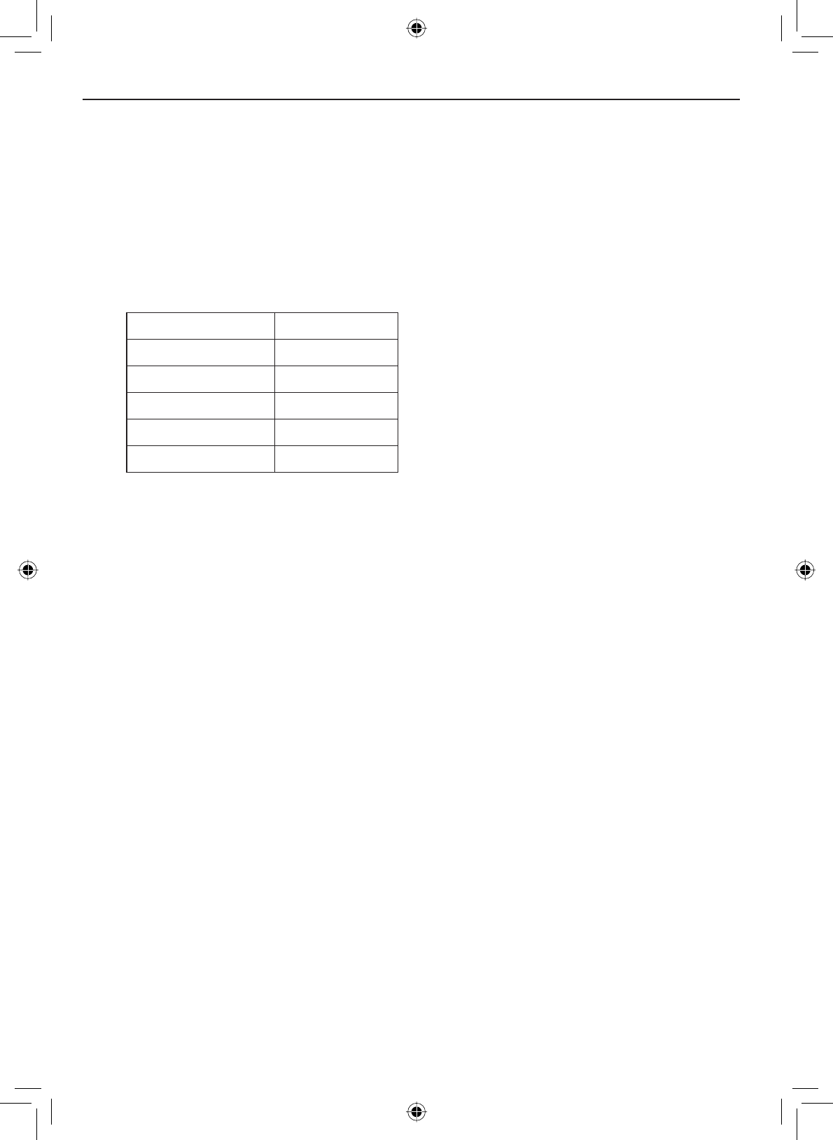
Specifications
E-66
NMEA Operation
This radio supports NMEA0183 version 3.01.
NMEA Input
,I\RXKDYHGLI¿FXOW\JHWWLQJWKH9+)WRUHFHLYHGDWDIURP\RXU*36UHFHLYHU
FKHFNWKHGHYLFH¶VFRQ¿JXUDWLRQ,WVKRXOGEHVHWWRWKHSDUDPHWHUVVKRZQLQ
Table 15.
Table 16 - NMEA Input Parameters
Baud rate 4800 bps
Data bits 8
Parity None
Stop bits 1
Data amplitude Over 3.0 V
Drive capability Over 10 mA
The radio supports RMC, GLL, GNS,
GGA and ZDA sentences. When
these sentences are received, the
radio displays latitude/longitude,
date, time, course, and speed. If
DQ\VHQWHQFHH[FHSWDQ50&RU
GLL sentence is received, the radio
uses the information based on the
following priority order.
• Status:RMC > GLL > GNS > GGA
• Latitude/Longitude:RMC > GLL > GNS > GGA
• UTC Time: RMC > GLL > GNS > GGA > ZDA
• Date: RMC > ZDA
• Speed / Course:RMC
NOTES :
• If the radio receives only a GLL sentence, the radio does not display the
current speed, course, and date.
• If the radio receives both RMC and GLL sentences, the radio uses only
the RMC sentence.
• Status data is used to check whether the GPS data is valid or invalid.
NMEA Output
When the radio receives a DSC call (Distress, Position Reply, or Position
Send), it outputs a DSC/DSE sentence from the NMEA output port. NOTE:
When the radio receives a distress call, it outputs a sentence in the following
format.
• $CDDSC,12,3081234000,,07,00,0354013946,0657,,,S,E*6D
• $CDDSE,1,1,A,3081234000,00,60875646*13

E-67
Regulations and Safety Warnings
FCC and Industry Canada Information
&HUWL¿FDWLRQ FCC Part 80 or RSS-182/188
Output Power 1 Watt (low) and 25 Watts (high)
Emission 16K0G3E, 16K0G2B
Transmitter Frequency Range 156 to 158 MHz
Lead warning
The cords on this product and/or accessories contain lead, a chemical known
to the State of California to cause birth defects or other reproductive harm.
Wash hands after handling. West Marine works to reduce lead content in
our PVC coated cords in our products and accessories.
Antenna Selection and Installation
Your VHF650 has been designed to accommodate all of the popular marine
VHF antennas. However, the selection and the proper installation of the
antenna is the responsibility of the user or installer.
7KH)&&KDVGHWHUPLQHGWKDWH[FHVVLYHUDGLDWLRQSRVHVDKHDOWKULVNWR
people near radio transmitting antennas. Therefore, the antenna used with
this radio should be installed using the following guidelines to ensure a safe
distance between the antenna and persons close by.
Small whip antennas (3 dB) or smaller should be installed with at least 3
feet away from any area where people are likely to be.
Larger antennas (6 dB or 9 dB) should be installed with at least 6 feet
away.
While the radio is transmitting, do not come closer to the antenna than
the recommended safe distance.
Do not touch the antenna when the radio is powered on and might begin
transmitting.
•
•
•
•

E-68
WARRANTOR: WEST MARINE AMERICA CORPORATION (“West Marine”)
ELEMENTS OF WARRANTY: West Marine warrants, for three years, to the original
retail owner, this West Marine Product to be free from defects in materials and crafts-
PDQVKLSZLWKRQO\WKHOLPLWDWLRQVRUH[FOXVLRQVVHWRXWEHORZ
WARRANTY DURATION: This warranty to the original user shall terminate and be of
no further effect 36 months after the date of original retail sale. The warranty is invalid
if the Product is
(A) damaged or not maintained as reasonable or necessary,
%PRGL¿HGDOWHUHGRUXVHGDVSDUWRIDQ\FRQYHUVLRQNLWVVXEDVVHPEOLHVRUDQ\
FRQ¿JXUDWLRQVQRWVROGE\:HVW0DULQH
(C) improperly installed,
(D) serviced or repaired by someone other than an authorized West Marine service
center for a defect or malfunction covered by this warranty,
(E) used in any conjunction with equipment or parts or as part of any system not
manufactured by West Marine, or
(F) installed or programmed by anyone other than as detailed by the Operating Guide
for this product.
STATEMENT OF REMEDY: In the event that the product does not conform to this
warranty at any time while this warranty is in effect, warrantor will repair the defect
DQGUHWXUQLWWR\RXZLWKRXWFKDUJHIRUSDUWVVHUYLFHRUDQ\RWKHUFRVWH[FHSWVKLS-
ping and handling) incurred by warrantor or its representatives in connection with
the performance of this warranty. THE LIMITED WARRANTY SET FORTH ABOVE
IS THE SOLE AND ENTIRE WARRANTY PERTAINING TO THE PRODUCT AND
IS IN LIEU OF AND EXCLUDES ALL OTHER WARRANTIES OF ANY NATURE
WHATSOEVER, WHETHER EXPRESS, IMPLIED OR ARISING BY OPERATION OF
LAW, INCLUDING, BUT NOT LIMITED TO ANY IMPLIED WARRANTIES OF MER-
CHANTABILITY OR FITNESS FOR A PARTICULAR PURPOSE. THIS WARRANTY
DOES NOT COVER OR PROVIDE FOR THE REIMBURSEMENT OR PAYMENT
OF INCIDENTAL OR CONSEQUENTIAL DAMAGES. Some states do not allow this
H[FOXVLRQRUOLPLWDWLRQRILQFLGHQWDORUFRQVHTXHQWLDOGDPDJHVVRWKHDERYHOLPLWDWLRQ
RUH[FOXVLRQPD\QRWDSSO\WR\RX
LEGAL REMEDIES:7KLVZDUUDQW\JLYHV\RXVSHFL¿FOHJDOULJKWVDQG\RXPD\DOVR
have other rights which vary from state to state. This warranty is void outside the
United States of America.
PROCEDURE FOR OBTAINING PERFORMANCE OF WARRANTY: If, after follow-
ing the instructions in this Operating Guide you are certain that the Product is defec-
tive, pack the Product carefully (preferably in its original packaging). Include evidence
of original purchase and a note describing the defect that has caused you to return it.
The Product should be shipped freight prepaid, by traceable means, or delivered, to
warrantor at:
West Marine
32%R[
Watsonville, CA 95077-0070
Three Year Limited Warranty