Uniden America UT655 VHF Fixed Mounted Marine Transceiver User Manual Part 1
Uniden America Corporation VHF Fixed Mounted Marine Transceiver Part 1
Contents
- 1. User Manual Part 1
- 2. User Manual Part 2
- 3. User Manual Part 3
- 4. User Manual Part 4
User Manual Part 1
UM385
RADIO MARITIME ASN HYDROFUGE
WATERPROOF DSC MARINE RADIO
OWNER’S MANUAL
GUIDE D’UTILISATION
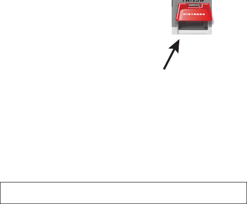
MAKING A DISTRESS CALL
Lift the red cover. Press and hold the
DISTRESS
button for three seconds. Your radio
transmits your boat’s location every few minutes until you receive a response.
#
NOTE: IF
the radio displays Enter User MMSI, cancel the automatic distress call and make a
normal voice distress call.
MAKING A VOICE DISTRESS CALL
SPEAK SLOWLY — CLEARLY — CALMLY.
For future reference, write your boat’s name & call sign here:
1. Make sure your radio is on.
2. On the microphone, press the
16/9-TRI
button to switch to Channel 16 (156.8 MHz).
(If the corner of the display does not show 16, press the
16/9-TRI
button again until it
does.)
3. Press the PUSH TO TALK button on the microphone and say: MAYDAY –
MAYDAY – MAYDAY.”
4. Say “
THIS IS {name or call sign of your boat}
.”
5. Say “
MAYDAY {name or call sign of your boat}.
”
6. Tell where you are: (what navigational aids or landmarks are near, or read the
latitude and longitude from your GPS).
7. State the nature of your distress, e.g. are you sinking, medical emergency, man
8. Give number of persons aboard and conditions of any injured persons.
9. Estimate present seaworthiness of your ship (e.g. how immediate is the danger due
10.
11. Say: “
I WILL BE LISTENING ON CHANNEL 16.
”
12. End message by saying “
THIS IS {name or call sign of your boat}, OVER.
”
13. Release the
PUSH TO TALK
button and listen.
If you do not get an answer after 30 seconds, repeat your call, beginning at
step 3, above.
Lift the red cover
and press the
DISTRESS button.

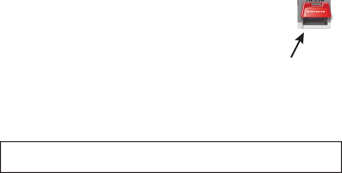
FAIRE UN APPEL DE DÉTRESSE
Soulevez le couvercle rouge. Maintenez la touche
DISTRESS
enfoncée
pendant trois secondes. Votre radio transmet l’emplacement de votre
bateau toutes les quelques minutes jusqu’à ce qu’il reçoive une réponse.
#REMARQUE : Si la radio affiche Enter User MMSI (Entrer l’ISMM de
l’utilisateur), annulez l’appel de détresse automatique et faites un
appel de détresse couvercle rouge etvocal standard.
FAIRE UN APPEL DE DÉTRESSE VOCAL
Parlez lentement – clairement – calmement.
Pour toute référence ultérieure, transcrivez ci-dessous le nom et l’indicatif d’appel de votre
bateau :
1. Vérifiez si votre radio est en marche.
2. Appuyez sur la touche
du microphone afin de commuter au canal 16 (156,8
MHz). (Si le canal 16 n’apparaît pas à l’affichage, appuyez de nouveau sur la touche
TRI
jusqu’à ce qu’il soit affiché.)
3. Appuyez sur le bouton de microphone
PUSH TO TALK
et dites :
MAYDAY.”
4. Donnez l’identité de votre navire en disant : “
ICI {nom de votre bateau ou le numéro
d’identification de votre bateau”}
.
5. Dites “
MAYDAY
{nom de votre bateau ou le numéro d’identification de votre bateau”}
.
6. Donnez votre position : (quels sont les points de repère ou aides à la navigation près de
vous ou lisez les coordonnées de longitude et de latitude apparaissant sur votre dispositif
GPS).
7.
urgence médicale, un homme à la mer, un incendie, nous sommes à la dérive, etc.
8. Révélez la nature de l’assistance désirée (médicale, remorquage, essence, etc.)
9. Donnez le nombre de personnes à bord et les conditions des blessés, s’il y en a.
10. Donnez la condition de navigabilité actuelle de votre navire, tel que le degré de l’urgence
11.
“Blue Duck est un yacht de croisière de 32 pieds, avec une coque blanche et un rouffle
bleu.).
12. Dites : “
JE VAIS ÉCOUTER SUR LE CANAL 16”
13. Terminez le message en disant “
ICI {nom de votre bateau ou le numéro d’identification de
votre bateau”}.
À VOUS”.
14. Relâchez le bouton
PUSH TO TALK
du microphone et écoutez.
Si vous n’obtenez pas de réponse après 30 secondes, répétez l’appel en commençant à
l’étape 3 ci-dessus.
Soulvez le couvercle
rouge et appuyez sur le
bouton DISTRESS.
CÓMO HACER UNA LLAMADA DE SOCORRO
Levante la tapa roja. Mantenga oprimido el botón
DISTRESS
por
tres secundos. La radio transmitirá la localidad de su nave cada
cuantos minutos hasta que reciba una respuesta.
#Nota: Si la radio exhibe (Inserte el MMSI del usuario), cancele la
llamada de socorro automática y haga una llamada de socorro
normal por voz.
CÓMO HACER UNA LLAMADA DE SOCORRO POR VOZ
Hable despacio -- claro -- y con calma.
Para acordarse en el futuro, escriba el nombre y la señal de su nave aquí:
1. Asegúrese de que su radio está encendida.
2. En el micrófono, oprima el botón
para cambiar al canal 16 (156.8MHz).
(Si la esquina de la pantalla no muestra 16, oprima el botón
otra vez hasta que lo
haga.)
3. Oprima el botón
PUSH TO TALK
(Oprima para hablar) en el micrófono y diga: “MAYDAY
---MAYDAY--- MAYDAY.”
4. Diga “ESTE ES {nombre de su nave o la señal de su nave).”
5. Diga “MAYDAY {nombre o señal de su nave}”.
6. Describa donde se encuentra: (ayudas de navegación o marcas destacadas cercanas, o
lea la latitud y la longitud en su GPS).
7. Describa la clase de su apuro, ej., se está hundiendo, emergencia médica, hombre al
agua, hay fuego, está a la deriva, etc.
8. Describa el tipo de asistencia que necesita (atención médica, remolque, bombas, etc.).
9. Describa la cantidad de personas abordo y las condiciones de cualquier persona
lesionada.
10. Estime la navegabilidad actual de su nave, (ej., cuanto de inmediato es el peligro de
11. Describa brevemente su nave (largura, tipo, color, casco).
12. Diga: “ESTARÉ ESCUCHANDO EN EL CANAL 16.”
13. Termine el mensaje diciendo: “ESTE ES {nombre o señal de su nave}, OVER.”
14. Suelte el botón
PUSH TO TALK
y escuche.
Si no recibe una contestacion dentro de 30 segundos, repita su llamada, comenzando con
el paso 3, descrito arriba.
Visite www.uniden.com para bajar el manual en español de la radio UM385.
Levante la tapa roja y
oprima el botón DISTRESS.
CONTENTS
MAKING A VOICE DISTRESS CALL ..........................................................................II
FAIRE UN APPEL DE DÉTRESSE VOCAL .................................................................III
CÓMO HACER UNA LLAMADA DE SOCORRO POR VOZ .......................................IV
INTRODUCTION .................................................................................1
FEATURES .............................................................................................................. 1
EXPLANATION OF TERMS ...................................................................................... 1
GETTING STARTED ................................................................................................. 2
What’s Included ................................................................................................. 2
Parts of the Radio ............................................................................................. 2
Parts of the Microphone ..................................................................................... 3
TURNING ON THE RADIO ....................................................................................... 4
................................................... 4
HOW IT WORKS ..................................................................................................... 4
.................................................................................... 5
Using the radio in normal mode ......................................................................... 6
Scan Mode ......................................................................................................... 7
Weather Mode .................................................................................................. 8
USING YOUR RADIO ............................................................................................... 9
Using Your Radio ............................................................................................. 10
............................................................... 13
................................................... 14
What is an MMSI Number? ............................................................................... 15
Entering MMSI Numbers .................................................................................. 15
Using the Directory ........................................................................................... 17
............................................................ 19
Receiving a DSC Call .......................................................................................... 21
Test Calls .......................................................................................................... 22
........................................................................ 26
............................................................ 26
Renaming Channels ......................................................................................... 26
INSTALLING THE HARDWARE .......................................................... 28
MOUNTING THE RADIO ....................................................................................... 28
CONNECTING THE RADIO ..................................................................................... 29
........................................................................ 30
............................................................................ 32
MAINTENANCE AND TROUBLESHOOTING ...................................... 32
ENGINE NOISE SUPPRESSION .............................................................................. 34
SPECIFICATIONS ............................................................................... 35
RADIO SPECIFICATIONS ...................................................................................... 35
REFERENCE TABLES ............................................................................................. 36
...................................................... 36
MARINE RADIO CHANNEL CHART ........................................................................ 37
.......................... 41
......................................... 41
Types of Events................................................................................................. 41
No Response Event Code .................................................................................. 43
NMEA OPERATION ............................................................................................... 44
NMEA Input ...................................................................................................... 44
NMEA Output .................................................................................................. 44
REGULATIONS AND SAFETY WARNINGS ........................................ 45
MARITIME RADIO SERVICES OPERATION ........................................................... 45
BASIC RADIO GUIDELINES .................................................................................... 45
FCC PART 15 / IC COMPLIANCE ........................................................................... 45
FCC Part 15 ....................................................................................................... 45
IC ...................................................................................................................... 46
ANTENNA SELECTION AND INSTALLATION ........................................................ 46
.................................................. 46
INTRODUCTION
FEATURES
radio is resistant to damage from rain or splashing water.
• Advanced DSC Class D functions, including Test Calling
• Channel select buttons on the microphone
succession.
to 25 watts for added transmission distance.
high or too low.
9 in the background.
• All marine VHF channels for the U.S., Canada, and international waters
• National Oceanic and Atmospheric Administration (NOAA) weather channel watch
EXPLANATION OF TERMS
Term What it Means
DSC Digital Selective Calling. A VHF radio standard for communicating
among boats and sending automated distress calls.
FIPS Federal Information Processing Standard. A set of location codes
roughly equivalent to your county codes.
WX Weather Radio
GPS Global Positioning System
NMEA National Marine Electronics Association. The organization that governs
standards for electronic equipment used on boats. NMEA 0183 is the
standard for serial data communication used by GPS.
MMSI
Maritime Mobile Service Identity number. A unique, nine-digit number
that identifies you and your boat when making DSC calls. It is also used
by the Coast Guard if you send an automated distress call.
Station Any DSC radio, whether it’s operated on a boat, at a marina, or by a
shore station.
1
GETTING STARTED
What’s Included
VHF Marine Radio
Mounting Bracket and Knobs
Microphone Mounting Hanger and
Mounting Hardware
Mounting Hardware
DC Power Cable Accessory Cable
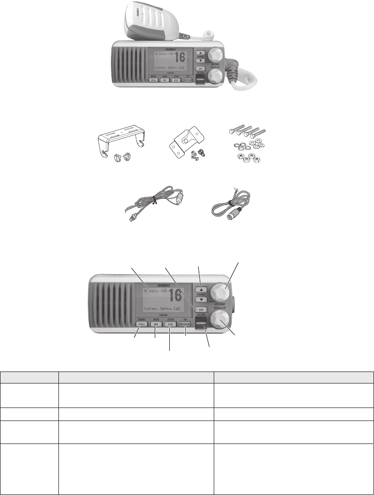
Parts of the Radio
SQUELCH knob
(turn clockwise
to decrease
channel noise)
16/9-TRI
(triple/dual-watch)
button
CLR-SCAN
(channel
scan) button
WX-MEM
button
CALL-MENU
button DISTRESS
button with
cover
LCD
display
ENT- 1W/25W
button
VOLUME-PWR (power)
knob (turn clockwise to
increase volume)
CHANNEL UP /
CHANNEL DOWN
buttons
Button Press to... Press and hold to...
Choose an option on a menu or to
display the GPS data.
Change the transmit power (see
page 16).
CHANNEL UP
Move up one channel at a time. Move quickly up the channels.
CHANNEL
DOWN
Move down one channet at a time. Move quickly down the channels.
1st press: Go to Channel 16.
2nd press: Go to Channel 9.
3rd press: Go back to the original
channel.
Go into Triple Watch or Dual Watch
mode (see page 17).
2
Button Press to... Press and hold to...
Go to previous menu or cursor
position in menu mode.
Start scanning the channels saved
in memory.
Listen to the current weather
conditions in your area.
Save a channel into memory or
remove a channel from memory.
Display the call menu. Display the normal menu.
DISTRESS
Select the nature of your distress
for a distress call.
Transmit a distress call.
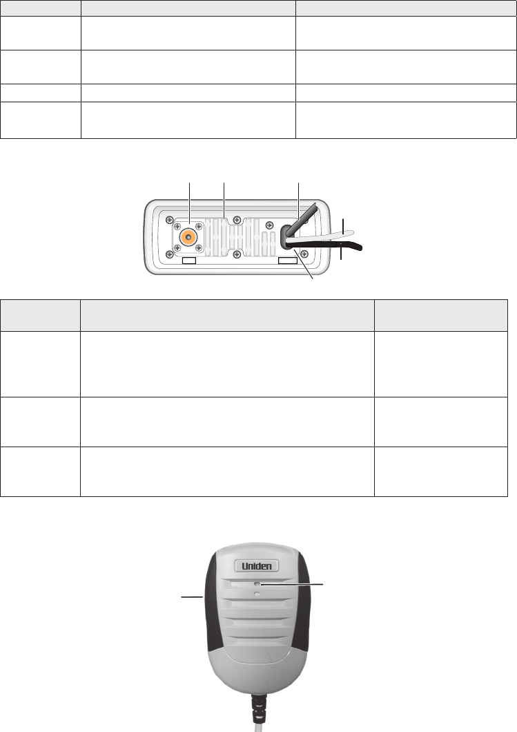
13.8V DC
ANTENNA
Black wire
(-)
Red wire
(+)
Power
Cable
Antenna
connector Heat sink Accessory
cable
Connector/
Cable Connects to... For details, see ...
Antenna
connector
External VHF antenna with a male PL259
(SO238) connector and 50 Ω impedance.
Minimum 4 ft, 3dB rated antenna for sailboats, 8
ft, 6 dB rated for power boats.
Connecting the radio
(see page 39).
Power cable
pigtail
Nominal 13.8 VDC power supply with negative
ground (10.5 VDC to 16.0 VDC) (Red wire +,
black wire -).
Connecting the radio
(see page 39).
Accessory
cable pigtail
GPS receiver, GPS chartplotter, External
Speaker.
Connecting
accessories (see
page 40)
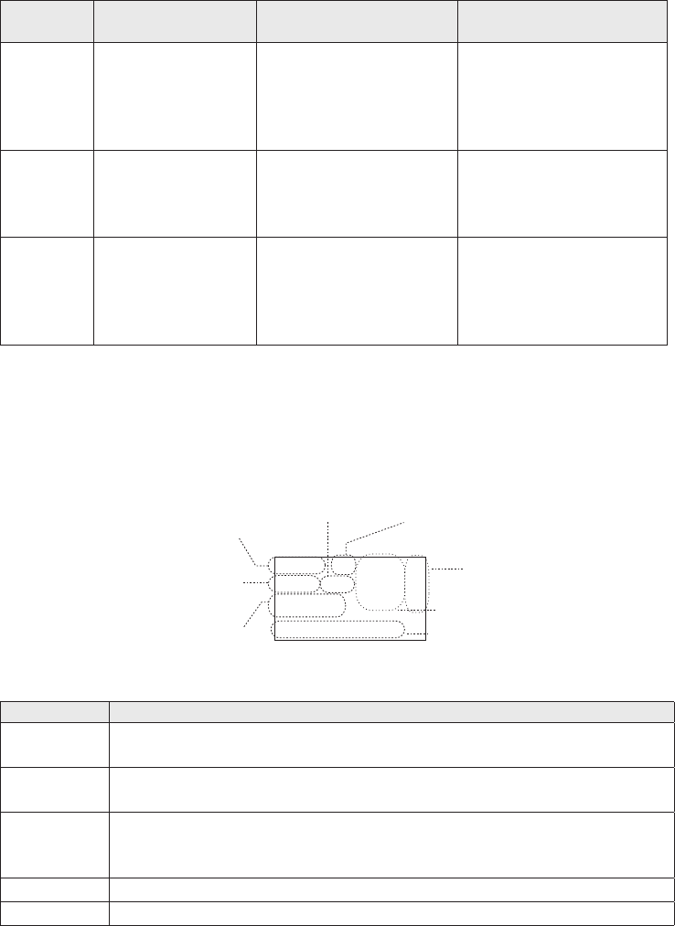
Parts of the Microphone
Push-to-Talk
Button
Microphone
3
TURNING ON THE RADIO
Turn the
knob clockwise to turn on the radio. As it powers on, the radio
displays the user MMSI number; if there is no MMSI set, the radio displays
MMSI not entered.
When it powers on, the radio selects the last channel used.
The radio comes preset to use the UIC channels assigned for the United States. If you are
operating in an area that uses Canadian or international UIC channels, you will need to
change the channel mode.
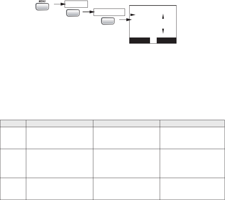
16
UIC Channels
USA Mode
Canada
Mode
Intl Mode
Back[CLR]
Select[ENT]
Setup
Press and hold -
CALL
USA/CAN/INT
ENT
1W/25W
ENT
1W/25W
1. Press and hold
to display the normal menu, and choose the Setup sub-
menu.
2. Select
USA/CAN/INT
. The screen displays the UIC channel setup.
3. Choose the channel mode you want to use: US (USA Mode), Canadian (Canada
Mode), or international (Intl Mode).
4. Press
HOW IT WORKS
Your radio has three basic modes of operation:
Mode What It Does Use It When To Turn it on./off...
Normal
Monitors a single marine
radio channel and lets
you talk on that channel.
You want to talk to
another station on a
specific channel.
(default mode)
Scan
Monitors all the
channels you save into
memory.
You have a small group
of channels you use
most often and want to
check them for traffic.
Press and hold the
CLR-SCAN button.
Weather Monitors the selected
NOAA weather channel.
You want to hear the
current and forecasted
weather in your area.
Press the WX-MEM
button.
In addition to the three basic operation modes, your radio also provides three different
“watch” modes which you can activate during any of the three basic modes. In these
watch modes, the radio briefly checks for activity on a specific channel then returns to its
previous mode.
4
Watch
Mode What It Does Use It When To Turn it on./off...
Weather
Alert
Checks for alerts
on the last weather
channel you
used every seven
seconds.
You want to be made
aware of severe weather
conditions in your area.
Select WX-ALERT Mode in
Setup submenu, and then
choose ON or OFF.
Triple
Checks for activity
on channels 16
and 9 every two
seconds.
You want to monitor a
channel yet maintain a
watch on channels 16
and 9.
Press and hold
16/9-TRI
for
two seconds.
Dual
Checks for activity
on channel 16
every two seconds.
You want to monitor a
channel yet maintain a
watch on channel 16.
Change Triple Watch
to Dual Watch in the
Setup menu, then press
and hold
16/9-TRI
for two
seconds.
#NOTE: You are required to monitor channel 16 whenever your boat is underway. You
should have either Triple Watch or Dual Watch on at all times.
Normal mode monitors whatever channel you select, and you can transmit on that channel
also. While using normal mode, the display lets you see the following information (not all
indicators will display at the same time):
25
Marine Operator
25 Watts USA
Memory Alert
GPS Data OK
Transmit power
(1 W or 25 W)
Current channel
is stored in
memory
Status messages
(see the status
message table)
Current
channel
number
Current channel
name (if the name
is too long, the
name line scrolls)
Channel mode
(USA, CANadian,
or INTernational)
Weather Alert
Watch on
Status
Icons
Message Meaning
GPS Data
OK The radio is receiving valid GPS data.
Check GPS The radio is not receiving valid GPS data: check the GPS status screen
andthe GPS connection.
Input
Position
The radio has been unable to receive valid GPS data for at least four
hours; it can no longer track your position. You need to manually input
your position (see Setting the GPS position manually on page 19).
Battery Low The battery voltage output is too low (below 10.5 VDC).
Battery High The battery voltage output is too high (above 16.0 VDC).
5
Using the radio in normal mode
xTo transmit, press and hold
PUSH TO TALK
on the microphone. Release the button when
you are finished talking.
xFor the best sound quality, hold the microphone about two inches from your mouth
while you’re talking.
xPress
CHANNEL UP
on the radio or the microphone to move up one channel at a time.
Press and hold either button to scroll quickly up the channels.
xPress
CHANNEL DOWN
on the radio or the microphone to move down one channel at a
time. Press and hold either button to scroll quickly down the channels.
xTo change the transmit power, press and hold
for two seconds. The
transmit power switches between 1 watt and 25 watts each time you press and hold
.
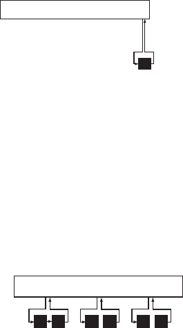
Normal mode with Weather Alert Watch
If you activate Weather Alert Watch while operating in normal mode, the radio checks
the most recently-used weather channel every seven seconds. If it detects a weather alert
for your area, it will change the channel to the last-used weather channel. The radio will
not check the weather channel while you are actively transmitting; it waits until your
transmission is finished and then checks the weather channel.
To turn Weather Alert Watch on or off, press and hold
while the radio is
idle. Select
Setup
and then
WX-Alert Mode
. Use
CHANNEL UP
and
CHANNEL DOWN
to choose
WX Alert Mode
setting
ON
or
Off
.
wx
Every 7 seconds,
the radio checks the
most recently-used
weather channel.
with WX Alert on
Monitoring Channel 25
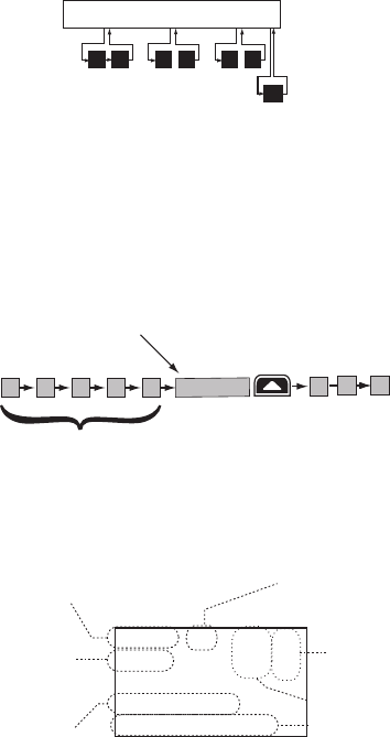
Normal mode with Triple and Dual Watch
If you activate Triple Watch while operating in normal mode, the radio checks channels
16 and 9 every two seconds; with Dual Watch turned on, the radio only checks channel 16.
The radio will not check channels 16 or 9 while you are actively transmitting; it waits until
your transmission is finished and then checks the channels.
Press and hold
Dual Watch on or off. (To change between Triple or Dual Watch, see page 17.)
09 16 09 16 09 16
Triple Watch: Every 2 seconds,
the radio checks channels 9 & 16.
Monitoring Channel 25
6
Normal mode with both Weather Alert and Triple/Dual Watch
performs both checks at their scheduled time.
wx
WX Alert : Every 7 seconds,
the radio checks the most
recently-used weather channel.
09 16 09 16 09 16
Triple Watch: Every 2 seconds,
the radio checks channels 9 & 16.
Monitoring Channel 25
Scan Mode
You can save channels into memory and then use scan mode to monitor those channels.
When the radio detects a signal on a channel, it pauses on that channel as long as the signal
is received; when the transmission stops, the radio will continue scanning.
11
1008 1312 17
15 20
14
The radio scans about
5 channels in 1 second.
When it detects a signal, the radio stays on the
channel until you press the CHANNEL UP button or the
signal stops.
Resume scan
In scan mode, you can get the following information from the display (some indicators will
not always be displayed).
1 Watt USA
Memory
Scanning Channels
01A,05A,06,07A,08
07 A
Transmit power
last used
Channel mode
(USA, CANadian,
or INTernational)
Current channel
being scanned
Scan list (if the
text is too long,
the line scrolls)
All scanned
channels must
be in memory
Normal scan
mode or Triple/
Dual-watch on
Status
icons
Using the radio in scan mode
xYou cannot transmit while in scan mode.
xYou must have two or more channels in memory to start a scan.
xTo save a channel into memory, select the channel, then press and hold
for
two seconds. Memory will show on the display.
xTo remove a channel from memory, set the radio to that channel, then press and hold
for two seconds. Memory will no longer show on the display.
xTo activate scan mode, press and hold
. Press and hold
again to
return to the previous mode.
xWhen the radio automatically stops on a channel, press
CHANNEL UP
to leave that
channel and resume scanning.
7
xTo end the scan, press the microphone’s
PUSH TO TALK
,
, or
buttons. The radio remains on the last scanned channel.
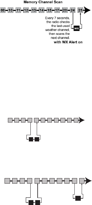
Scan mode with Weather Alert Watch
If you activate Weather Alert Watch while operating in scan mode, the radio checks the
most recently-used weather channel every seven seconds, then continues scanning the
To turn Weather Alert Watch on or off, press and hold
while the radio is idle.
CHANNEL UP
and
CHANNEL DOWN
Alert Mode setting On or Off.
Scan mode with Triple and Dual Watch
If you activate Triple Watch while operating in scan mode, the radio checks channels 16
on, the radio only checks channel 16.
Press and hold
Dual Watch on or off. (To change between Triple or Dual Watch, see page 17.)
Press and hold the
Watch mode.
09 16
Triple Watch : Every 2
seconds, the radio checks
channels 9 & 16 then goes on
to the next channel.
Memory Channel Scan
08 252417151413121110 20
Scan mode with both Weather Alert and Triple/Dual Watch
performs both checks at their scheduled time.
09 16
Triple Watch:
Every 2 seconds,
the radio checks
channels 9 & 16
then goes on to
the next channel.
WX Alert : Every 7
seconds, the radio
checks the last-used
weather channel,
then scans the next
channel.
wx
Memory Channel Scan
08 252417151413121110 20
Weather Mode
In cooperation with the FCC, NOAA also uses the weather channels to alert you of other
hazards besides weather (child abduction alerts, nuclear, biological, etc.). In weather mode,
the radio monitors one of the ten NOAA weather channels. If any type of alert is received
for your area, the radio sounds an alert tone and displays the type of alert. In weather
mode, the display shows the following:
8
09
Hurricane Warning
Weather Band
Alert
Weather
mode is on
Current
channel
number
Type of alert
(If the text is too
long, it scrolls.)
Flashing: An alert
has been issued
Steady: Weather
Alert Watch is on
Using the radio in weather mode
xYou cannot transmit while in weather mode.
xTo enter weather mode, press
.
xWeather mode can filter out alerts that do not affect your location if the location code
(FIPS code) of the alert is entered in your radio (see page 17). If you have no FIPS codes
programmed into your radio, the radio will notify you of all alerts in any area.
xTo turn off the radio’s alert tone, press any button.
xTo cancel weather mode and return to the previous marine channel, press the
button again.
Weather mode with Weather Alert Watch
Because weather mode already monitors the weather channels, you don’t need Weather
Alert Watch to check the weather channel every seven seconds. If you activate Weather Alert
Watch while operating in weather mode, it operates as a type of “sleep mode”: the radio stays
on the weather channel and mutes the speaker. If an alert is detected for your area, the radio
sounds an alert tone and turns the speaker back on. This mode is very useful when you are
anchoring for the night but want to stay informed of any hazards in your area.
To turn Weather Alert Watch on or off, press and hold
while the radio is idle.
Select
Setup
and then
WX-Alert Mode
. Use
CHANNEL UP
and
CHANNEL DOWN
Alert Mode setting
On
or
Off
.
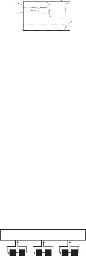
Weather mode with Triple and Dual Watch
If you activate Triple Watch while operating in weather mode, the radio checks channels
16 and 9 every two seconds; with Dual Watch turned on, the radio only checks channel 16.
Press and hold
Dual Watch on or off. (To change between Triple or Dual Watch, see page 17.)
09 16 09 16 09 16
Triple Watch: Every 2 seconds, the
radio checks channel 9, then channel 16.
Monitoring Weather Channel WX08
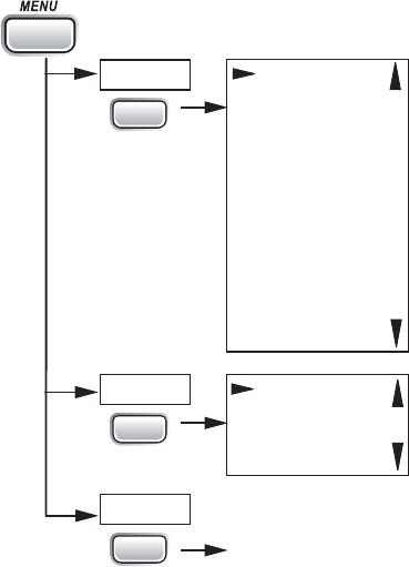
USING YOUR RADIO
To display the radio call menu, press
. To display the radio normal menu, press
and hold
. The menu has the following options:
9
USA/CAN/INT
Dual/TriWatch
GPS Setup
FIPS Codes
Auto CH SW
POS Reply
Test Reply
Channel Name
Group MMSI
User MMSI
WX Alert Mode
[Exit]
Contrast
Lamp Adjust
Key Beep
[Exit]
(Close Menu)
Setup
System
[Exit]
Press and hold -
CALL
ENT
1W/25W
ENT
1W/25W
ENT
1W/25W
Using Your Radio
xAn arrow on the left side indicates the current selection.
xPress
CHANNEL UP
on the radio or the microphone to move up a line in the menu; if you
are at the top line in the menu, the cursor jumps to the bottom of the menu.
xPress
to choose the selected item.
xPress
CHANNEL DOWN
on the radio or the microphone to move down a line in the
menu; if you are at the bottom line of the menu, the cursor jumps to the top of the
menu.
xPress
to go back to the previous menu screen.
xFrom any menu screen, choose Exit or press and hold
to close the menu
screen.
Making a Voice MAYDAY Call
(see inside front cover)
Seng the Volume
Turn the volume knob clockwise to increase the speaker volume; turn it counter-clockwise
to decrease the volume.
Seng the Squelch Level
The squelch feature reduces the level of static on the speaker by filtering out the
background channel noise. At the lowest squelch level, the speaker plays all radio signals,
10

including any noise on the channel. Setting the squelch level higher filters out channel
noise and lets only actual radio transmissions through.
Weak signals
No
Squelch
Medium
Squelch
High
Squelch
Strong signals
Noise
While listening to a channel, adjust the
SQUELCH
knob until the noise is filtered out and
you can only hear the transmission. If you switch to a channel with a lot of noise or with a
weak transmission, you may need to adjust the squelch level again.
#NOTE: Setting the squelch level too high may prevent you from hearing weaker
transmissions. If you are having difficulty hearing a transmission, try setting the squelch
level lower.
Changing the Channel
Press
CHANNEL UP
and
CHANNEL DOWN
briefly to scroll through the channels one channel
at a time. Press and hold
CHANNEL UP
or
CHANNEL DOWN
to quickly scroll through the
channels.
Making a Transmission
To make a transmission, press and hold the microphone
PUSH TO TALK
button. Release the
PUSH TO TALK
button when you’re finished talking to let the other party respond.
xTo prevent stuck microphone problems or situations where
PUSH TO TALK
is pushed
accidentally, the radio limits your talk time to 5 minutes in a single transmission. If you
talk for over 5 minutes continuously, the display shows RELEASE MIC BUTTON.
xFor the best sound quality, hold the microphone about two inches away from your
mouth.
xYou cannot transmit while the radio is in weather mode or scan mode.
xSee the channel lists beginning on page 36 for a list of receive-only channels.
Boosng the Transmission Power
In most situations, the 1 Watt transmission power is all you need. If you find yourself far
away from other stations and have trouble getting a response, you may need to boost the
transmission power from 1 Watt to 25 Watts:
1. Select the channel you want to transmit on.
2. Push and hold
for two seconds. The display shows
25 Watts
in the
upper left hand corner.
3. The transmit power remains at 25 Watts until you change the setting back. Push
and hold
for two seconds. The display shows 1 Watt.
11
#NOTE: Don’t forget to change the transmission setting back to 1 Watt when you move
closer to other stations.
#NOTE: By default, when you change to channel 16, the radio automatically boosts the
power to 25 Watts. Be sure to change the power back to 1 Watt if you are not making an
emergency transmission.
Watt so that there is less interference between boaters attempting to use the channel at
the same time. If you switch to one of these channels, the radio changes back to 1 Watt
automatically. See the channel lists beginning on page 36 for a list of power-restricted
channels.
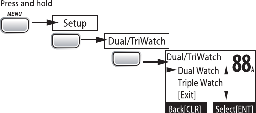
Choosing Triple Watch or Dual Watch
In Triple Watch mode, the radio briefly checks channels 16 and 9 every two seconds. In
Dual Watch mode, the radio checks channel 16 only. Generally, Triple Watch is used in
areas where channel 9 is used as a hailing frequency while Dual Watch is used in areas
where channel 16 is used for distress and hailing. Your radio comes set to use Triple
Watch; if you want to use Dual Watch instead, you will have to select it in the setup:
1.
CALL
ENT
1W/25W
ENT
1W/25W
Press and hold
CALL MENU
to display the normal menu.
2. Select
Setup
and then
Dual/Tri Watch
.
3. Choose
Dual Watch
and press
. The radio activates the new setting and
returns to the Setup menu.
4. To reactive Triple Watch, repeat the procedure described above, but choose Triple
Watch in step 3.
Using FIPS Codes for Weather Alerts
The US National Weather Service established 6-digit Federal Information Processing
System (FIPS) codes to issue weather alerts in specific areas. You can choose which areas
you want to hear alerts for by entering these FIPS codes in your radio. This can prevent
you from being bothered by events that are far from where you are boating. The radio only
sounds the alert tone if an incoming FIPS code matches one of the areas you selected.
xFor more information about how the NWS uses FIPS codes, see the NWS website: www.
x
12

xFor information on the Canadian implementation of FIPS codes, called Canadian
#NOTE: If you travel outside the areas you have entered into your radio, you may not hear
alerts that affect your new location. Be sure to enter the FIPS codes of all the areas you
plan to travel to during this trip.
Follow the steps below to edit the list of FIPS codes. You can store up to 30 different FIPS
codes in your radio.
1.
000000
Use the up and down arrows
to adjust each of the six
digits in turn.
16
FIPS Code
Back[CLR]
Forward[ENT]
FIPS Codes
Setup
Press and hold -
[New]
CALL
ENT
1W/25W
ENT
1W/25W
ENT
1W/25W
Display the normal menu and choose the Setup sub-menu.
2. Select
FIPS Codes
. The screen displays any previously-entered FIPS codes.
3. To add a new FIPS code, select
New
.
4. Use
CHANNEL UP
and
CHANNEL DOWN
CHANNEL
UP
increases the number and
CHANNEL DOWN
decreases it.
5.
a mistake while entering a digit, press
to erase the wrong number and
moved the cursor to the left digit.
6.
. The radio displays the new
Yes
; to cancel this code,
select
No
. The radio returns to the list of FIPS codes.
7.
8. To delete the FIPS code, select
Delete
. To edit the code, select
Edit
, then use
CHANNEL UP
and
CHANNEL DOWN
9.
Exit
to close the menu
screen.
Contrast
Your radio display has 10 levels of contrast. To adjust the contrast, press and hold
MENU
while the radio is idle. Select System and then Contrast. Use
CHANNEL UP
and
CHANNEL DOWN
to change the contrast to your desired level.
To restore the default contrast setting, turn the radio off. Press
and hold it in
while you turn the radio on.
Lamp adjust
Your radio has 10 brightness levels on the display. To adjust the brightness, press and hold
while the radio is idle. Select System and then Lamp Adjust. Use CHANNEL UP
and CHANNEL DOWN to change the brightness to your desired level.
13
Turning the key beep on and o
Key beep is the tone that sounds when you press a key or a button. To turn off the key
beep, press and hold
while the radio is idle. Select System and then Key Beep.
Choose
OFF
to turn off the key beep.
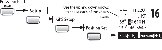
Seng the GPS Posion Manually
If the radio is not receiving valid GPS data, the radio displays Input Position. Follow the
steps below to manually input your position.
#NOTE: Be certain any manually-entered position is correct. If you enter the wrong position
and then make a DSC distress call, you will be telling the arrows to adjust each of the
values in turn.
CALL
ENT
1W/25W
ENT
1W/25W
ENT
1W/25W
1. Display the normal menu and choose the Setup sub-menu.
2. Select
GPS Setup
and then choose
Position Set
.
3.
highlights the hour. Use
CHANNEL UP
and
CHANNEL DOWN
to set the displayed hours
to match coordinated universal time (UTC, also call Greenwich Mean Time and
a mistake while entering a digit, press
to erase the wrong number and
moved the cursor to the left digit.
4. The cursor moves to highlight the minutes. Use
CHANNEL UP
and
CHANNEL DOWN
to adjust the minutes and press
.
5. The cursor moves to highlight the degrees latitude. As you update each value,
CHANNEL UP
and
CHANNEL DOWN
to adjust the number and press
.
6. When you have entered the last value, the radio returns to the GPS Setup menu.
What is DSC?
Digital Selective Calling (DSC) is a standard that allows you to call other stations using
their unique identification code (the Maritime Mobile Service Identity or MMSI number),
just like you would call a phone number. To call another station, just enter that station’s
MMSI number and choose the voice channel you want to talk on. The radio uses channel
70 to transmit your MMSI number to the other station along with the voice channel you
requested. If the other station accepts your call, both radios automatically switch to the
requested voice channel so you can talk to the other station.
14

DSC provides a system for automated distress calls. At the touch of a button, the radio can
transmit your MMSI number, the nature of your distress, and your current position based
on data from your GPS receiver. The radio repeats the distress call every few minutes until
it receives an acknowledgement.
The DSC standard dedicates a VHF channel—channel 70—to digital transmissions only.
Since digital transmissions require less bandwidth voice transmissions, channel 70 avoids
the problems of busy voice channels.
Advanced DSC Features
Your radio supports the following DSC features:
Feature Menu Item Function
Individual Call Individual Contact another vessel from your directory.
Group Call Group Contact all vessels that share your group
MMSI code.
All Ships Call All Ships Broadcast to all vessels within range (used for
safety or advisory messages).
Position Request POS Request Request the current location of another vessel.
Position Send Position Send Transmit your current location to another
vessel.
Test Call Test Make sure your radio is working and
configured correctly.
Name and MMSI
Directory Directory Store a list of 20 names and MMSI
identification codes for DSC calls.
Standby Mode Standby Automaticcally respond to all DSC calls within
an “Unavailable” status.
Received Call
Log Receive Log Display the last 10 distress calls received by
the radio and the last 20 general calls.
What is an MMSI Number?
In order to use DSC features, you must be assigned an MMSI number and program that
number into your radio. There are two kinds of MMSI numbers: individual numbers for
use by single boats and group numbers for use by fleets, boating organizations, event
coordinators, etc.
You can get more information on MMSI numbers at these resources:
xThe dealer where you purchased the radio
xRecreational boaters can obtain an MMSI number from the Boat Owner’s Association
563-1536) or Sea Tow Services
xCommercial boaters need a ship station license to get an MMSI number. For more
Entering MMSI Numbers
Individual or User MMSI Number
15
#NOTE: Be sure you have the correct User MMSI number before entering it in the radio.
The radio only allows you to enter the user MMSI once. If you need to re-enter the User
MMSI number, Visit our webiste for assistance at www.uniden.com
.
Follow the steps below to enter your individual or user MMSI number into the radio:
1.
CALL
ENT
1W/25W
ENT
1W/25W
ENT
1W/25W
Display the normal menu and choose the Setup sub-menu.
2. Select
User MMSI.
(If an MMSI number was already entered, the screen displays it
with the message
Cannot change over 1 time
.
Visit our webiste for assistance at www.
uniden.com
.
3. Use
CHANNEL UP
and
CHANNEL DOWN
CHANNEL
UP
increases the number and
CHANNEL DOWN
decreases it.
4.
digit. Enter the remaining eight digits of the MMSI number in the same way. If
you make a mistake while entering a number, press
to erase the wrong
number and the cursor is moved to the left digit.
5. When the ninth digit is correct, press
The radio displays the new
#NOTE: Be sure you entered the number correctly before confirming the entry. You can
only save the user MMSI once.
6.
MMSI number, select
No
. The radio returns to the Setup menu.
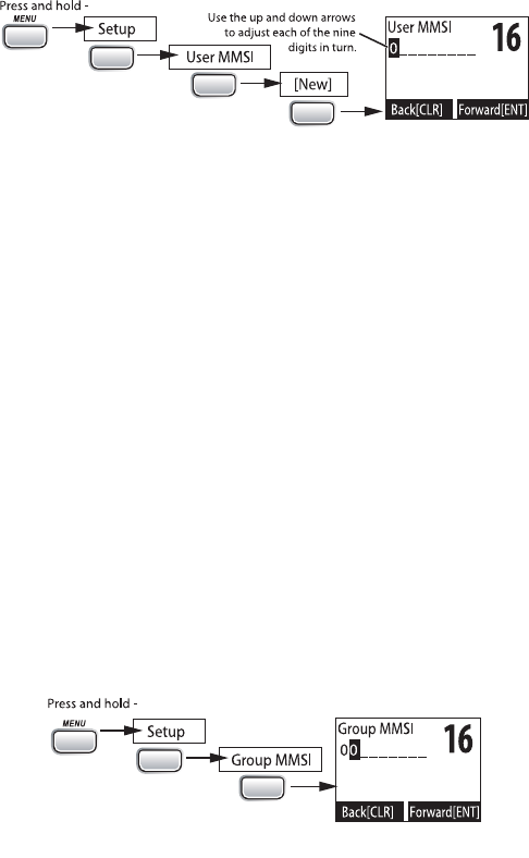
Group MMSI number
You can change the group MMSI number as often as you want. Follow the steps below to
enter a group MMSI number into the radio:
CALL
ENT
1W/25W
ENT
1W/25W
1. Display the normal menu and choose the Setup sub-menu.
2. Select
Group MMSI
. If one was entered previously, the screen displays it.
3. Group MMSI numbers always start with a 0, so that digit is already entered for
you. Use
CHANNEL UP
and
CHANNEL DOWN
to change the second of the nine digits;
CHANNEL UP
increases the number and
CHANNEL DOWN
button decreases it.
4. When the second digit is correct, press the
. The cursor moves to the
16
If you make a mistake while entering a number, press
to erase the wrong
number and the cursor is moved to the left digit.
5. When the ninth digit is correct, press
. The radio displays the new
6. To save this MMSI number, select
Yes
number, select
No
. The radio returns to the Setup menu.
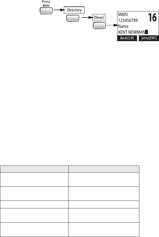
Using the Directory
The directory lets you store up to 20 MMSI numbers of other stations so you can call them
quickly.
CALL
ENT
1W/25W
ENT
1W/25W
Follow the steps below to edit the MMSI numbers in your directory:
1. Press
to display the call menu.
2. Select
Directory
. The screen displays any previously-entered MMSI numbers and
names.
3. To add a new MMSI number to the directory, select
New
.
4. The radio prompts you to enter the nine-digit MMSI number. Use
CHANNEL UP
and
CHANNEL DOWN
CHANNEL UP
button increases the
number and the
CHANNEL DOWN
button decreases it.
5.
digit. Enter the remaining eight digits of the MMSI number in the same way. If
you make a mistake while entering a number, press
to erase the wrong
number and the cursor is moved to the left digit.
6. When the ninth digit is correct, press
.
7. The radio prompts you to enter a name for this MMSI number; the name is what
you will see in the directory list. Each name can be up to 12 characters. Use
CHANNEL UP
and
CHANNEL DOWN
scroll through the available characters according to the following table:
Channel Up Button Channel Down Button
Capital letters (A through
Z) One blank space
Lower-case letters (a
through z) Numbers (0 through 9)
Punctuation (/ ‘ + -) Punctuation (/ ‘ + -)
Numbers (0 through 9) Lower-case letters (a
through z)
One blank space Capital letters (A through
Z)
17

8.
button. The cursor moves
is shorter than 12 characters, press and hold
to complete the name
entry. (If you press and hold
without entering a name, the radio uses
the MMSI number in the directory list.) If you make a mistake while entering a
number, press
to erase the wrong number and the cursor is moved to left
digit.
9.
Yes
; to cancel this
directory entry, select
No
. The radio returns to the directory list.
10.
11. To delete the directory entry, select
Delete
. To edit the code, select
Edit
, then use
CHANNEL UP
and
CHANNEL DOWN
to edit the MMSI number and the name.
12.
Exit
to close the menu screen.
Making DSC Calls
There are essentially four different types of DSC voice calls:
Call type What it does When to use it
Distress
Alerts all stations that you need
assistance and sends them your
current position.
In an emergency only.
Individual Calls a single station using the
User MMSL.
Any time you want to talk to another
station.
Group Calls all the stations that have the
same Group MMSL as yours.
Any time you want with the whole
group you are traveling with at the
same time.
All Ships Calls all stations within range of
your radio.
Safety warnings (e.g., debris in the
water) or any urgent situation.
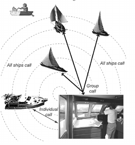
Suppose you are coordinating safety for a sailboat race. Before the race starts, you instruct
all the racers to enter your group MMSI number into their radios. During the race:
xThroughout the race, you use group calling to update the racers on the time, race
status, and any course corrections.
xA power boat full of spectators comes a little too close to the race path. You use
individual calling to contact the power boat and advise them to stay clear of the race.
xYou see a rowboat entering the area, but since it doesn’t have a radio, you can’t
communicate with the rowboat. You use all ships calling to alert all the other boats in
the area of the possible danger.
18
To call a single station with DSC, follow the steps below:
1. Press
to display the call menu.
2. Select
Individual
.
3. The radio displays the names listed in your directory; use
CHANNEL UP
and
CHANNEL DOWN
to choose the directory entry you want to call and press
1W/25W
. If you want to call a station that is not in your directory, select
Manual
.
The radio prompts you to enter the MMSI number you want to call. Enter the MMSI
number the same way you enter directory entries (see page 22) Enter all nine
digits and press
.
4. The radio prompts you to select a response channel. Use
CHANNEL UP
and
CHANNEL
DOWN
to scroll through the available channels. When you reach the channel you
want to use for a response, press the
button.
5.
If you want to call the displayed MMSI number, select
Send
. To cancel the call, select
Cancel
.
6. The radio automatically switches to channel 70 to transmit the call request.
xWhen the other station accepts the call, both radios switch to the selected response
channel for voice transmission.
xIf the other station cannot respond on the channel you selected, the radio displays Not
support CH.
19

Calling a parcular group of staons (Group Call)
Group calling calls all the stations that share your group MMSI. You must have a group
MMSI programmed into the radio to make a group call, and the stations (boats) you are
calling must have this same group MMSI programmed into their radios.
1. Press
to display the call menu.
2. Select
Group
.
3. The radio prompts you to select a response channel. Use
CHANNEL UP
and
CHANNEL
DOWN
to scroll through the available channels. When you reach the channel you
want to use for a response, press
.
4.
Send
to continue with the call or select
Cancel
to cancel the call.
5. The radio switches to channel 70 to transmit the call request then automatically
switches to the designated response channel.
Calling all staons (All-Ships Call)
All ships calling contacts all DSC radios within range of your boat. You should only use all
ships calling in the event of a Safety warning (such as debris in the water) or to request
assistance in an Urgency (any situation where your vessel has a serious problem but is not
yet in distress).
1. Open the call menu.
2. Select
All Ships
, and then choose whether this is an Urgency call or a Safety call.
3.
Send
to continue with the call or select
Cancel
to cancel the call.
4. The radio automatically switches to channel 70 to transmit the call request then
automatically switches to channel 16, the designated response channel for all-ships
calling.
Making an Automac Distress Call
If you have programmed your MMSI number, your radio can transmit an automated
distress call with your current location and nature of the distress. The radio then monitors
the channel 16 for a response and repeats the distress call every few minutes until it
receives an acknowledgement.
#NOTE: To send an automatic distress call, press and hold DISTRESS for three seconds.
If no MMSI number has been programmed, the radio prompts you to enter your MMSI
number.
If you want to include the nature of your distress in the distress call, use the following
distress procedure:
1. Press
DISTRESS
.
2. The radio displays the list of distress conditions; use
CHANNEL UP
and
CHANNEL
DOWN
to choose the nature of your distress, then press and hold
DISTRESS
for three
seconds.
Undesignated Sinking Fire
Adrift Flooding Abandoning
20
Collision Piracy. Armed Grounding
Overboard Capsizing
3. If no MMSI number has been programmed, the radio prompts you to enter your
MMSI number.
Canceling an automac distress call
While the radio is waiting for a response, it gives you the option of canceling the call. To
cancel the distress call, choose Cancel and press
.
Receiving a DSC Call
If your radio receives an individual DSC call from another station, it sounds an incoming
call tone and displays the name or MMSI number of the station calling you. To respond to
the call, select Send: Able-Comply; the radio sends an acknowledgement and automatically
switches to the designated response channel. To reject the call, select Send: Unable-Comply;
the radio advises the other station that you are unable to respond to the call.
If the DSC request contains a response channel that you are not allowed to use, the radio
displays Not Support CH; your only response option is Send: Unable-Comply.
If the radio receives a group or all ships call, it sounds an incoming call tone and
automatically switches to the designated response channel.
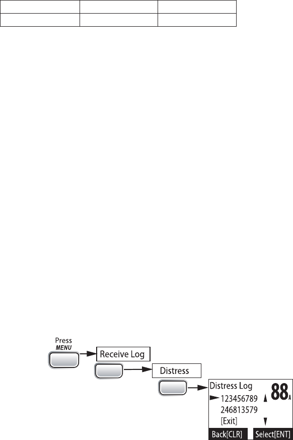
Receive log
Just like your telephone’s caller ID list, your radio keeps track of the calls you receive but
do not answer. The receive log is useful if you have been off your boat or away from your
radio and want to see who has tried to contact you. The radio displays the last 10 distress
calls and the last 20 non-distress calls that it received. If you have unread incoming DSC
calls, the radio displays a Message icon. When you display all Distress and Other receiving
logs, the message icon disappears.
CALL
ENT
1W/2.5 W
ENT
1W/2.5 W
1. Press
to display the call menu.
2. Select
Receive Log
.
3. Select
Distress
to see the last 10 distress call received by the radio. Select
Other
to see the last 20 normal calls received by the radio, then choose from
Individual
,
Group
, or
All Ships
calls.
4.
The display blinks if there are new calls you have not reviewed.
21

5. Select the call you want to see the details of. Use
CHANNEL UP
and
CHANNEL DOWN
to see all of the information. The log displays different information depending on
type of call received. See the table below for the information stored for each type of
call:
DSC Call Type Receive Log Information
Distress MMSI (or name), position, time, nature code.
Distress
Acknowledge MMSI (or name), distress MMSI, position, time, nature code.
Distress Relay MMSI (or name), distress MMSI, position, time, nature code.
Distress Relay
Acknowledge MMSI (or name), distress MMSI, position, time, nature code.
Geographical MMSI (or name), category code, communication channel number.
All Ships MMSI (or name), category code, communication channel number.
Group MMSI (or name), category code, communication channel number.
Individual MMSI (or name), category code, communication channel number.
Individual
Acknowledge
MMSI (or name), Completed/Unattended, category code,
communication channel number.
Test MMSI (or name), category code.
Test
Acknowledge MMSI (or name), category code.
Pos Reply MMSI (or name), position, time, category code.
Pos Request MMSI (or name), category code.
Pos Send MMSI (or name), position, time, category code.
6. Press
7. From the log menu, select
Exit
to close the receive log and return to the mode you
were in.
Returning a call
You can return individual calls directly from the receive log. From the call detail screen,
press
CHANNEL DOWN
until Call Back appears at the bottom of the display. Press
1W/25W
to return that station’s call.
Test Calls
Making Test Calls (Test)
You can use the test call feature to make sure your radio is working and configured
correctly. To avoid overloading coastal receiving stations, you should limit test calls to
these stations to once a week.
#NOTE: Many coastal stations have specific frequencies and MMSI numbers you should use
for making test calls. Before making a test call to a coastal station, be sure to check the
Local Notice to Mariners (LNM), issued every week by the US Coast Guard. The LNMs for
each region are available online at http://www.navcen.uscg.gov/lnm/default.htm.
1. Press
to display the call menu.
22
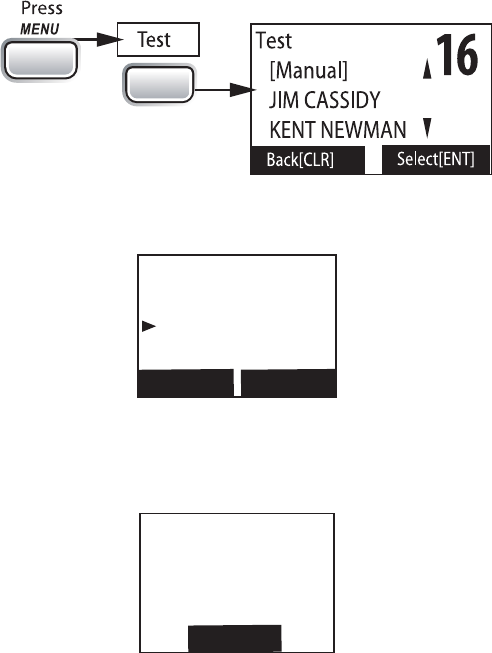
2. Select
Test
.
3. The radio displays the names listed in your directory; use
CHANNEL UP
and
CHANNEL DOWN
to choose the directory entry you want to send a test call to and
press
button. If you want to send a test call to a station that is not in
your directory, select
Manual
. The radio prompts you to enter the MMSI number
you want to call. Enter the MMSI number the same way you enter directory entries
(see page 22). Enter all nine digits and press
button.
4.
CALL
ENT
1W/25W
If you want to call the displayed number, select
Send
. To cancel the call, select
Cancel
.
5.
16
Test
123456789
Send
Cancel
Back[CLR] Select[ENT]
The radio automatically switches to channel 70 to transmit the test call request,
then switches back to the last-used channel.
6. When the other station acknowledges the test call, the radio displays an
acknowledgement screen.
16
Test
Acknowledged
123456789
Completed
Back[CLR]
Receiving Test Calls
When another station sends you a test call, the radio displays the test request screen.
xTo acknowledge the test call, select Reply.
xTo reject the test call, select Cancel.
23
16
Test
123456789
Reply
Cancel
Select[ENT]
Back[CLR]
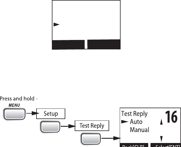
Enabling automac test call reply
If you want the radio to automatically reply to all test call, you can enable automatic test
call reply.
1. Press and hold
to display the normal menu.
2. Select
Setup
and then
Test Reply
. Choose
Auto
and press
. The radio will
automatically send an acknowledgement when it receives a test call.
CALL
ENT
1W/25W
ENT
1W/25W
3. To disable automatic test call reply, repeat the steps above and select
Manual
.
Posion Request and Reply
Requesting another station’s position (POS Request)
Anytime you need to know where another boat currently is—to find your boating partners,
to respond to a request for assistance, etc.—you can send a position request to their radio:
1. Press
to display the call menu.
2. Select
DSC Call
sub-menu, then select
POS Request
.
3. The radio displays the names listed in your directory; use
CHANNEL UP
and
CHANNEL DOWN
to choose the directory entry you want to contact and press
1W/25W
. If you want to contact a station that is not in your directory, select
Manual
.
The radio prompts you to enter the MMSI number you want to call. Enter the MMSI
number the same way you enter directory entries (see page 22). Enter all nine
digits and press
.
4. The radio displays the MMSI number you are about to contact and asks you to
Send
. To cancel the request, select
Cancel
.
5. When the other station responds, the radio displays the MMSI number, the
longitude, and the latitude of the other station. If your radio is connected to
a chartplotter through the NMEA OUT connection (see page 43), the position
information will also be displayed on the plotter screen.
6. If the other station does not have valid GPS data, the radio displays
No Position
.
24

Receiving a posion request (Posion Reply)
When another station requests your current position, the radio displays the following screen:
16
POS Request
KENT NEWMAN
Reply
Cancel
Select[ENT]
Back[CLR]
To send your current position to the other station, select Reply; the radio transmits your
latitude and longitude to the other station. If you select Reply but the radio does not have
valid GPS data, it transmits the reply code with No Position.
To reject the position request, select Cancel.
Enabling automac posion reply
If you want the radio to automatically transmit your current position whenever it receives
a position request, you can enable automatic position reply. Most boaters activate
automatic position reply for safety reasons or because they subscribe to a marine towing
stations to get your position without your manual confirmation
1. Press and hold
to display the normal menu.
2. Select
Setup
and then
POS Reply
.
3. Choose
Auto
and press
ENT-1W/25W
. The radio will automatically transmit your
position when it receives a position request.
4. To disable automatic position reply, repeat the steps above and select
Manual
.
Sending your own posion (Posion Send)
If your radio is connected to a GPS receiver, you can send your boat’s position to someone
else. If you are requesting assistance or using an all ships call to give a safety warning, you
can send your current position so other stations know where you are:
1. Press
to display the call menu.
2. Select
Position Send
.
3. The radio displays the names listed in your directory; use
CHANNEL UP
and
CHANNEL DOWN
to choose the directory entry you want to contact and press
1W/25W
. If you want to contact a station that is not in your directory, select
Manual
.
The radio prompts you to enter the MMSI number you want to call. Enter the MMSI
number the same way you enter directory entries (see page 22). Enter all nine
digits and press
.
4. The radio displays the MMSI number you are about to contact and asks you to
select Send. To cancel the transmission, select
Cancel
.
5. The radio transmits your MMSI number, your longitude, and your latitude to the
other station.
25
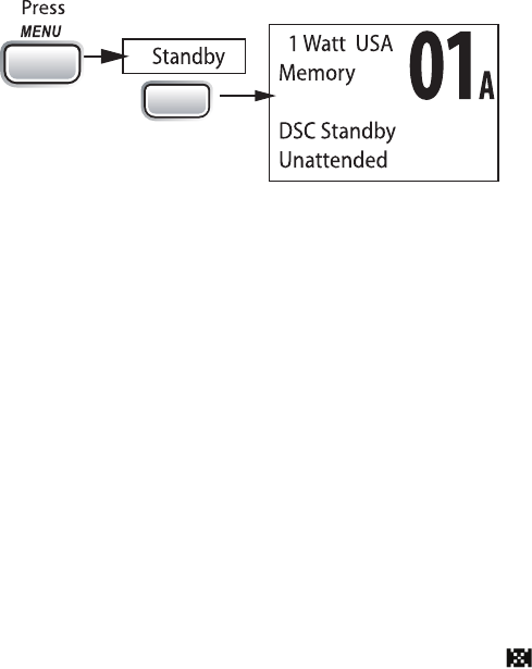
If you are leaving your radio or do not wish to answer any DSC calls, you can put your radio
in standby mode. If your radio receives an individual call, it will automatically respond
with a message that indicates your radio is currently unattended. Follow the steps below
to put your radio in standby:
CALL
ENT
1W/25W
1. Display the Call menu.
2. Select
Standby
to place your radio in standby mode. The radio displays the standby
screen, above.
3. To cancel standby and return to the mode your radio was in, press any button.
If you are involved in a bridge-to-bridge call, you may not want the radio to automatically
switch channels when it receives a DSC call. In cases like this, you can disable automatic
channel switching. If you receive an individual call, the radio will respond with an
unattended code, just as if the radio were in Standby.
1. Press and hold
to display the normal menu.
2. Select
Setup
and then
Auto CH SW
.
3. Choose
Off
and press
. The radio will not automatically switch channels
until you reactivate this feature.
#NOTE: Use this feature with caution. Deactivating automatic switching and then
forgetting it can make it hard for you to receive DSC calls.
If you have unread incoming DSC calls, the radio displays a message icon ( ). You will be
able to review who has called. The radio displays the last 10 distress calls and the last 20
non-distress calls it received (see the receive log on page 29).
Renaming Channels
If you discover that a marine radio channel has a different common name in your local
area, you can change the name of that channel to make it easier for you to use (see the
channel lists beginning on page 36 for the default channel names). To rename a channel,
follow the steps below:
1. Display the normal menu and choose the Setup sub-menu.
2. Select
Channel Name
. The screen displays the list of channels.
3. Use
CHANNEL UP
and
CHANNEL DOWN
to choose the channel you want to change
and press
.
4. Select
Rename
to enter a new name for this channel. The radio prompts you to
enter a new name for this channel. Each name can be up to 12 characters. Use
26
CHANNEL
UP
and
CHANNEL DOWN
5.
. The cursor moves to the
shorter than 12 characters, press and hold
to complete the name
entry. If you make a mistake while entering a number, press
to erase the
wrong number and the cursor is moved to the left digit.
6.
Yes
; to cancel the
change, select
No
. The radio returns to the channel list.
7. To restore a channel back to its original name, select the channel and choose
Default
.
8.
Exit
to close the menu screen.
27
INSTALLING THE HARDWARE
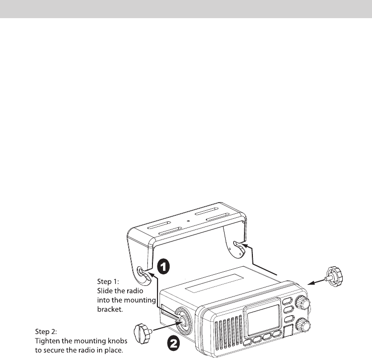
MOUNTING THE RADIO
Your radio can sit at any angle in the mounting bracket so it can easily accommodate
the best location. First, determine the best place to mount the radio. For optimum
performance, find a location that can:
x
You may need to use some type of anchor with the mounting screws to hold the radio,
depending on the surface.
xKeep the battery leads as short as possible.
xKeep the antenna lead-in wire as short as possible.
xAllow free air flow around the heat sink on the rear of the radio.
xAvoid interference with the ship’s compass.
1. Install the radio into the mounting bracket.
2. Position the radio into the desired location. Mark the edges of the bracket on the
mounting surface.
3.
Actual product image may vary slightly.
Remove the mounting bracket drill template from the back of the manual, and use
the template to mark the drill holes on the mounting surface.
4. Drill the holes for the mounting bracket; be sure to follow any special requirements
of the mounting surface.
5. Remove the bracket from the radio, and use the mounting hardware to secure the
bracket to the mounting surface.
28
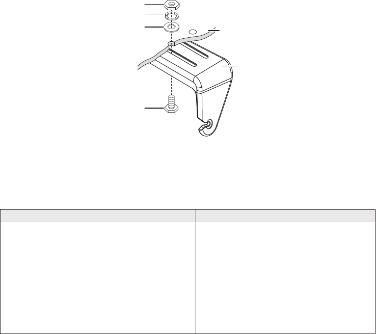
6.
Hex bolt
Washer
Spring washer
Hex nut
Mounting
bracket
Mounting
surface
Install the radio back into the mounting bracket.
CONNECTING THE RADIO
To operate correctly, your radio requires two electrical connections:
xproviding it with power from the boat’s electrical system
xconnecting a VHF-FM marine antenna to the antenna connector
Power Supply Requirements VHF Antenna Requirements
Nominal 13.8 VDC power supply with a
negative ground (10.5 VDC to 16.0 VDC).
Power leads should be kept as short as
possible. A direct connection to the power
supply is ideal.
Minimum of #14 AWG copper wire for
extensions up to 20 feet, 12 AWG wire for
extensions from 20 to 35 feet, or 10 AWG
wire for extensions from 35 to 60 feet.
Male PL-259 connector
50 Ω impedance
Minimum 3 foot, 3 dB rated antenna for
sailboats or 8 foot, 6 dB rated antenna
for powerboats
Minimum RG-58 lead-in wire for antenna
leads up to 20 feet, RG-8X for antenna
leads from 20 to 35 feet, or RG-8U for
antenna leads from 35 to 60 feet.
1. Connect the BLACK wire of the power cable to the NEGATIVE (-) side of your
power source.
2. Connect the RED wire of the power cable to the POSITIVE (+) side of your power
source.
#NOTE: To extend the life of the radio, use waterproof tape to seal electrical connections.
3. Install your antenna according to the manufacturer’s instructions.
4. If necessary, consult the FCC guidelines for antenna separation. See Antenna
Selection and Installation on page 63 for more details. (In summary, the FCC
recommends that antennas up to 3 dB be installed a minimum of 3 feet from any
occupied location; antennas over 3 dB should be installed at least 6 feet away.)
5. Connect the PL-259 connector from the antenna lead-in wires to the SO238
connector labeled ANTENNA on the back of your radio.
6. Plug the power cable into the power cable pigtail on the back of your radio.
29
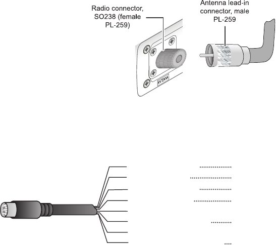
Use the accessory cable to connect the radio to a GPS receiver, a GPS chartplotter, and an
Yellow: NMEA_IN (+)
Red: External Speaker (+)
White: NMEA_OUT (+)
Orange: N/A
Black: GND/External Speaker (-)
Brown: NMEA_OUT (-)
Bare: Shield/GND
Green: NMEA_IN (-)
Accessory cable wires Connects to...
GPS receiver NMEA Data Output (-) or GND
GPS receiver NMEA Data Output (+)
Chartplotter NMEA Data Input (-)
Chartplotter NMEA Data Input (+)
Speaker (-)/GND
Speaker (+)
Connecng to a GPS Receiver
If you connect the radio to a GPS receiver, the radio can automatically transmit your
current position during an automated distress call or during a normal DSC call.
Your radio supports a standard NMEA0183 input from a GPS receiver. Follow the steps
below to connect your radio to your GPS receiver:
1. Connect the GREEN wire of the included accessory cable to the GPS DATA OUTPUT
(-) WIRE or the GROUND WIRE on your GPS receiver.
2. Connect the YELLOW wire of the included accessory cable to the GPS DATA
OUTPUT (+) WIRE on your GPS receiver.
3. Be certain all wire connections are secure and that all open wires are adequately
covered.
#NOTE: to extend the life of the radio, use waterproof tape to seal electrical connections.
4. Plug the accessory cable into the accessory cable pigtail on the back of your radio.
GPS Vericaon
If the GPS receiver is correctly connected and it transmits valid data, the display shows GPS
Data OK. Press
to open the GPS status screen and see detailed GPS data:
30
16
06/20 11:00:00
208o 30. 0 KT
35o 40. 610 N
139o 46. 564 E
GPS Data: External
Date
Time
Current
channel
Course
Latitude
Longitude Speed
Status
If the GPS does not send coordinates within 30 minutes, an audible alert sounds once and
the display shows Input GPS. This message remains until the coordinates are updated.
After 4 hours, the audible alert sounds again if no coordinates are received and the GPS is
connected. After 23.5 hours, the radio deletes the current coordinates and displays Input
GPS.
See page 19 to manually set the GPS coordinates.
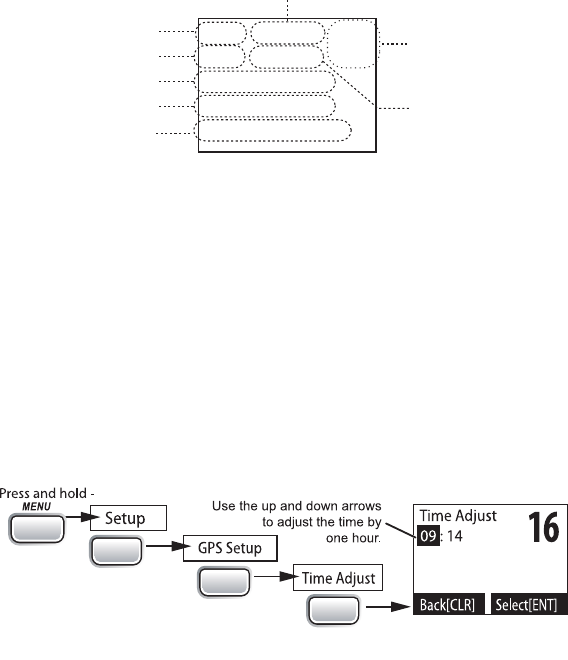
Conguring the GPS
If the radio is receiving valid GPS data, it will automatically set the clock to your local time
based on the GPS location. You can adjust your local time forward or back one hour if
for Daylight Savings Time.
Follow the steps below to adjust the time:
1.
CALL
ENT
1W/25W
ENT
1W/25W
ENT
1W/25W
Display the normal menu and choose the Setup sub-menu.
2. Select
GPS Setup
and then choose
Time Adjust
.
3. The display shows your current local time. To adjust the time forward one hour, use
CHANNEL UP
. To adjust the time back one hour, use
CHANNEL DOWN
button. Press
4.
Set
to save the new time or
Cancel
5. If your local area observes Daylight Savings Time, choose
Daylight Save
and press
the
button.
6. If Daylight Savings Time is currently in effect, select
On
. If Daylight Savings Time is
not currently in effect, select
Off
.
7. Press
. The radio activates the new time setting and returns to the GPS
Setup menu.
31

Your radio provides a standard NMEA0183 GPS output that you can connect to a
chartplotter. When it receives another boat’s position data in a DSC call, the radio sends
the position data to the chartplotter so you can see the location:
1. Connect the BROWN wire of the accessory cable to the NEGATIVE (-) wire of your
chartplotter’s NMEA data INPUT.
2. Connect the WHITE wire of the accessory cable to the POSITIVE (+) wire of your
chartplotter’s NMEA data INPUT
3. Be certain all wire connections are secure and that all open wires are adequately
covered.
#NOTE: To extend the life of the radio, use waterproof tape to seal electrical connections.
Connecng to an External Speaker
in a noisy environment. If you adjust the
knob on the radio, it will also adjust
• Minimum impedance of 4 Ohms
• Minimum power handling of 10 Watts
1. Connect the BLACK wire of the accessory cable to the GROUND WIRE of your
2. Connect the RED wire of the accessory cable to the POSITIVE (+) WIRE of your
3. Be certain all wire connections are secure and that all open wires are adequately
covered.
#NOTE: To extend the life of the radio, use waterproof tape to seal electrical connections.
MAINTENANCE AND TROUBLESHOOTING
Due to its rugged design, your radio requires very little maintenance. However, it is a
precision electronic instrument, so you should follow a few precautions:
x
emergency. A defective antenna may cause damage to your radio.
xYou are responsible for continued FCC technical compliance of your radio.
xYou should arrange for periodic performance checks with your dealer.
Problem Things to Try
The radio won’t power on.
Check the power connections.
Check the fuse.
Check the master battery switch and branch circuit
that connect to the radio.
32

Problem Things to Try
The radio won’t transmit.
Make sure you are not in weather or scan mode.
Make sure you are not trying to transmit on a
receive-only channel (see the channels and
frequency tables beginning on page 50).
Make sure you are transmitting at the correct
power level for this channel (see the channels and
frequency tables beginning on page 50).
Make sure the duration of each transmission is less
than 5 minutes.
Noise comes out of the speaker
all the time Adjust the squelch level; it is probably too low.
I can’t hear anything (no volume)
from the speaker. Adjust the squelch level; it is probably too high.
I can transmit, but no one can
hear me.
Check your UIC channel settings [see Setting the
UIC channel mode (USA/CAN/INT) on page 5].
The display flashes, and I don’t
know why.
The display will flash if the radio is in a watch mode
or in scan mode. Try turning off scanning, Weather
Alert Watch, or Triple/Dual Watch (see page 11).
I can’t read the display.
Adjust the contrast and backlight brightness level (see
page 19).
The display is too bright at night.
Adjust the backlight brightness level.
Turn off the radio; hold
button and turn
it back on (see page 19).
I can’t see any words on the
display.
Reset the radio back to the default brightness level:
turn off the radio; hold the
button and
turn it back on.
I’m not getting any GPS data on
my display.
Make sure your GPS receiver is correctly
connected (see Connecting to a GPS receiver,
page 40).
Make sure your GPS receiver is working properly.
Make sure that your GPS receiver supports the
NMEA parameters described in NMEA Operation
on page 41.
I’m not getting any hazard alerts.
Make sure Weather Alert Watch is turned on.
Check to make sure the FIPS codes in your radio
include your current location (see Using FIPS
codes for weather alerts on page 17).
33

Problem Things to Try
I’m getting all the hazard alerts,
not just the ones for my area.
Check to make sure the FIPS codes in your radio
were entered correctly (see Using FIPS codes for
weather alerts on page 17).
Sometimes the Weather Alert Watch may catch
a hazard alert in the middle of the broadcast
and miss which FIPS codes are affected. For
your safety, the radio triggers the alert tone
and switches to the weather channel when this
happens.
I can’t make Group DSC calls. Make sure the Group MMSI was entered correctly.
Where can I find my radio’s
serial number?
Look on the right side of the radio (the side with the
microphone cord), behind the mounting bracket.
The radio won’t let me enter my
User MMSI. What do I do? Contact customer service.
ENGINE NOISE SUPPRESSION
Interference from the noise generated by the electrical systems of engines is sometimes a
problem with radios. Your radio has been designed to be essentially impervious to ignition
noise and alternator noise. However, in some installations it may be necessary to take
measures to further reduce the effect of noise interference. Your radio’s DC battery wires,
antenna lead, and accessory cables should be routed away from the engine and engine
compartment, and from power cabling carrying high currents. In severe cases of noise
interference, it may be necessary to install a noise suppression kit. Contact the dealer
where you purchased the radio for more information.
34

SPECIFICATIONS
All specifications are subject to change without notice.
RADIO SPECIFICATIONS
General
Controls Volume-Pwr, Squelch
Status Indicators
Transmit power, Scan mode, Triple Watch mode, Battery
High, Battery low, USA, CAN, INT, Alert, Memory, GPS,
Message, Weather band, GPS status and Channel Display
Display LCD (Full Dot Matrix)
Buttons ENT-1W/25W, Channel UP, Channel DOWN, CALL-MENU,
WX-MEM, CLR-SCAN, 16/9-TRI, and DISTRESS
Connectors and
Cables Antenna, accessory, and DC power
Size
H 2.62 inches x W 6.4 inches x L 5.12 inches (without Heat
Sink)
H 66.6 mm x W 162.6 mm x L 130.1 mm (without Heat Sink)
Weight 1.0 kg (2.2 pounds)
Supply Voltage Nominal 13.8V DC, negative ground (10.5 VDC to 16.0 VDC)
Standard Accessories Mounting bracket and hardware, microphone hanger,
Antenna Impedance 50 Ω nominal
Microphone Rugged 2 kΩ condenser mic element with coiled cord
Speaker 1.77 inch, 8 Ω
Operating
Temperature Range –4 °F to +122 °F (–20 °C to + 50 °C)
Shock and Vibration Meets or exceeds EIA standards, RS152B and RS204C
FCC Approvals Type accepted under part 80 of the Rules; meets Great Lakes
Agreement and party boat requirements
Transmitter
Power Output 1 watt or 25 watt (user selectable)
Power Requirement 25 watts output: 6A@13.8V DC
Modulation ±5 kHz deviation
Hum and Noise
Signal-to-Noise
45 dB@1 kHz with 3 kHz deviation with 1000 Hz modulating
frequency (nominal)
Audio Distortion Less than 8% with 3 kHz deviation with 1000 Hz modulating
frequency
Spurious Suppression –40 dBm @ Hi, –40dBm @ Lo
Output Power
Stabilization Built-in automatic level control (ALC)
Frequency Range 156 to 163 MHz
Frequency Stability ±10 ppm @ –20°C to + 50°C
Receiver
Frequency Range 156 to 163 MHz
35

General
Sensitivity 0.25 μV for 12 dB SINAD (nominal)
Circuit Dual Conversion Super Heterodyne PLL (Crystal for DSC)
Squelch Sensitivity 0.2 μV Threshold
Spurious Response 75 dB (nominal)
Adjacent Channel
Selectivity 75 dB @ ±25 kHz (nominal)
Audio Output Power 2.5 watts (10% Distortion, 8 Ω load)
Power Requirement 360 mA @ 13.8V DC at squelched, 920 mA @ 13.8V DC at
maximum audio output
IF Frequencies 1st 41.925 MHz, 2nd 455 kHz (1st 21.7 MHz, 2nd 455 kHz for
DSC)
REFERENCE TABLES
#NOTE: This radio does not support AIS channels.
The table below lists the display name or channel description used in the following tables
and what each description means.
Channel name/description Used for
DISTRESS SAFETY AND
CALLING
primarily emergency messages and distress
calls
INTERSHIP SAFETY safety messages from one ship to another, or
from a ship to Coast Guard aircraft
NON-COMMERCIAL (recreational
or voluntary ships only)
messages about the needs of the ship, including
fishing reports, rendezvous, scheduling repairs
and berthing information
COMMERCIAL (working ships
only)
messages about the needs of the ship or the
business the ship is engaged in
PUBLIC CORRESPONDENCE/
MARINE OPERATOR
calls to the marine operator at a public coast
station. Marine operators can connect you to
the telephone network so you can make and
receive calls. (There is usually a charge for this
service.)
PORT OPERATIONS/VTS (vessel
traffic system)
messages about the movement and safety of
ships in or near ports, locks or waterways. In
certain major ports, some channels may be
restricted to specific types of port operations
messages.
NAVIGATIONAL/BRIDGE TO
BRIDGE
messages about ship navigation, for example,
passing or meeting other ships, maneuvering
through locks, or navigating around
drawbridges. Messages must be short!
36

Channel name/description Used for
STATE CONTROL
messages about government regulation and
control, boating activities, or assistance to ships;
also used to talk to ships and coast stations
operated by state or local governments
DIGITAL SELECTIVE CALLING DSC signals only (no voice communications
allowed at any time)
MARINE RADIO CHANNEL CHART
Ch
No. USA INT CAN TX RX Channel Type/Name
01 x x 156.050 160.650 Public Correspondence (Marine
Operator)
01A* x 156.050 156.0500
Port Operation and Commercial
[VTS (Vessel Traffic System)] in
some areas.
02 x x 156.100 160.700 Public Correspondence (Marine
Operator)
03 x x 156.150 160.750 Public Correspondence (Marine
Operator)
04 x 156.200 160.800 Public Correspondence (Marine
Operator)
04A x 156.200 156.200 Canadian Coast Guard: West Coast
Commercial Fishing: East Coast
05 x 156.250 160.850
Public Correspondence (Marine
Operator). Ship Movement, Port
Operations
05A x x 156.250 156.250 Port Operations, Ship Movement,
VTS in some areas
06 x x x 156.300 156.300 Inter-ship safety
07 x 156.350 160.950 Public Correspondence (Marine
Operator)
7A x x 156.350 156.350 Commercial
08 x x x 156.400 156.400 Commercial (Inter-Ship Only)
09 x x x 156.450 156.450 Boater Calling, Commercial and
Non-Commercial
10 x x x 156.500 156.500 Commercial
11 x x x 156.550 156.550 Commercial, VTS in selected areas
12 x x x 156.600 156.600 Port Operations, VTS in selected
areas
37

Ch
No. USA INT CAN TX RX Channel Type/Name
13 x x x 156.650 156.650
Intership Navigation Safety (Bridge-
to-Bridge). Ships >20m length
maintain a listening watch on this
channel in US waters.
14 x x x 156.700 156.700 Port Operation, VTS in some areas
15 x Inhibit 156.750 Environmental (Receive Only)
15 x x 156.750 156.750
Inter-ship, Port Operations,
Commercial, Non-Commercial, Ship
Movement (1 Watt Only)
16 x x x 156.800 156.800 Distress, Safety, Calling
17 x x x 156.850 156.850 State and Local Govt Maritime
Control (1 Watt Only)
18 x 156.900 161.500 Port Operations, Ship Movement
18A x x 156.900 156.900 Commercial
Canada: Towing West Coast
19 x 156.950 161.550 Commercial
19A x x 156.950 156.950 Commercial
20 x x x 157.000 161.600 Port Operations
Canada: 1 Watt Only
20A x 157.000 157.000 Port Operation
21 x 157.050 161.650 Port Operations
21A x x 157.050 157.050 Coast Guard Only
21B x INHIBIT 161.650 Canadian CG Continuous Marine
Broadcast (CMB) Service
22 x 157.100 161.700 Port Operations, Ship Movement
22A x x 157.100 157.100
US and Canadian Coast Guard
Liaison and Airtime Safety
Information Broadcasts Announced
on Channel 16
23 x x 157.150 161.750 Public Correspondence (Marine
Operator)
23A x 157.150 157.150 US Coast Guard Only
23B x INHIBIT 161.750 Canadian CG Continuous Marine
Broadcast (CMB Service
24 x x x 157.200 161.800 Public Correspondence (Marine
Operator)
25 x x x 157.250 161.850 Public Correspondence (Marine
Operator)
25B x INHIBIT 161.850 Canadian CG Continuous Marine
Broadcast (CMB) Service
38

Ch
No. USA INT CAN TX RX Channel Type/Name
26 x x x 157.300 161.900 Public Correspondence (Marine
Operator)
27 x x x 157.350 161.950 Public Correspondence (Marine
Operator)
28 x x x 157.400 162.000 Public Correspondence (Marine
Operator)
28B x INHIBIT 162.000 Canadian CG Continuous Marine
Broadcast (CMB) Service
60 x x 156.025 160.625 Public Correspondence (Marine
Operator)
61 x 156.075 160.675 Public Correspondence (Marine
Operator)
61A x 156.075 156.075 Canadian Coast Guard: West Coast
Commercial Fishing: East Coast
62 x 156.125 160.725 Public Correspondence (Marine
Operator)
62A x 156.125 156.125 Canadian Coast Guard
63 x 156.175 160.775 Public Correspondence (Marine
Operator)
63A x x 156.175 156.175 VTS, Port Operations
64 x x 156.225 160.825 Public Correspondence (Marine
Operator)
64A x 156.225 156.225 Canada: Commercial Fishing Only
65 x 156.275 160.875 Public Correspondence (Marine
Operator)
65A x x 156.275 156.275 Port Operations
Canada: Towing West Coast
66 x 156.325 160.925 Public Correspondence (Marine
Operator)
66A x x 156.325 156.325 Port Operations
Canada: 1 Watt Only
67 x x x 156.375 156.375
US: Commercial, Bridge-to-Bridge,
VTS in some areas
Canada: Search and Rescue,
Commercial in some areas, Non-
Commercial on West Coast
68 x x x 156.425 156.425 Non -Cmmercial
69 x x x 156.475 156.475
Non-Commercial
Canada: Commercial East Coast.
Non-Commercial West Coast
39

Ch
No. USA INT CAN TX RX Channel Type/Name
70 x x x 156.525 156.525 DSC (Digital Selective Calling) Only.
No Voice Communications Allowed
71 x x x 156.575 156.575
US: Non-Commercial
Canada: Ship Movement West
Coast, Non-Commercial East Coast
72 x x x 156.625 156.625 Non-Commercial (Ship-to-Ship)
73 x x x 156.675 156.675 Port Operations
74 x x x 156.725 156.725 Port Operations
75 x x x 156.775 156.775 Port Operations (1 Watt Only)
76 x x x 156.825 156.825 Port Operations (1 Watt Only)
77 x x x 156.875 156.875 Port Operations (Ship-to-Ship)
78 x 156.925 161.525 Port Operations
78A x x 156.925 156.925 Non-Commercial, Inter-Ship
79 x 156.975 161.575 Port Operations
79A x x 156.9750 156.975 Commercial, Inter-Ship
80 x 157.025 161.625 Port Operationsx
80A x x 157.025 157.025 Commercial, Inter-Ship
81 x 157.075 161.675 Port Operations
81A x x 157.075 157.075 Government, Canadian Coast
Guard
82 x 157.125 161.725 Port Operations
82A x x 157.125 157.125 Government, Canadian Coast
Guard
83 x 157.175 161.775 Port Operations
83A x x 157.175 157.175 Coast Guard
83B x INHIBIT 161.775 Canadian CG Continuous Marine
Broadcast (CMB) Service
84 x x x 157.225 161.825 Public Correspondence (Marine
Operator)
85 x x x 157.275 161.875 Public Correspondence (Marine
Operator)
86 x x x 157.325 161.925 Public Correspondence (Marine
Operator)
87A x x x 157.375 157.375 Public Correspondence (Marine
Operator)
88A x x 157.425 157.425 Public Correspondence (Marine
Operator)
1019 x x 156.950 156.950 Commercial
1020 x x 157.000 157.000 Port Operations
1078 x x 156.925 156.925 Non-Commercial, Inter-Ship
1079 x x 156.975 156.975 Commercial, Inter-Ship
40
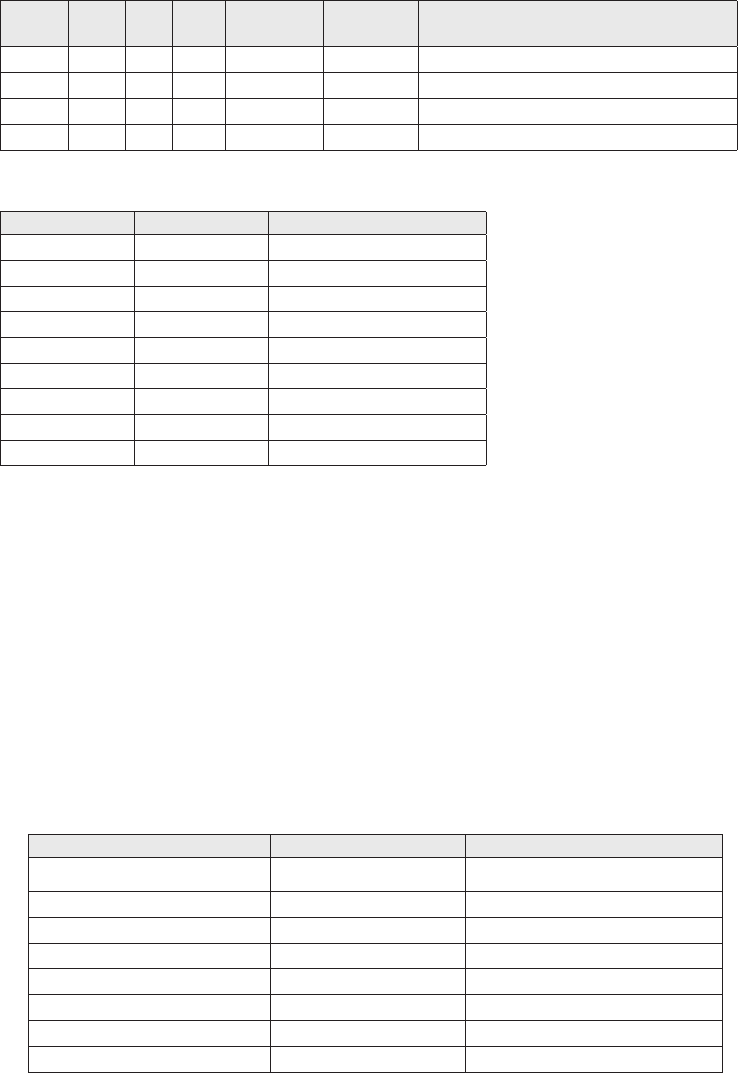
Ch
No. USA INT CAN TX RX Channel Type/Name
2019 x 161.550 161.550 Commercial
2020 x 161.600 161.600 Port Operations
2078 x 161.525 161.525 Port Operations
2079 x 161.575 161.575 Port Operations
Ch No. RX Freq Name on display
WX01 162.5500 162.550 MHz
WX02 162.4000 162.400 MHz
WX03 162.4750 162.475 MHz
WX04 162.4250 162.425 MHz
WX05 162.4500 162.450 MHz
WX06 162.5000 162.500 MHz
WX07 162.5250 162.525 MHz
WX08 161.6500 161.650 MHz
WX09 161.7750 161.775 MHz
Types of Events
x
property, probability of occurrence and location is high, and the onset time is relatively
short.
xA WATCH meets the classification of a warning, but either the onset time, probability of
occurrance, or location is uncertain.
xAn EMERGENCY is an event that, by itself, would not kill or injure or do property
damage, but indirectly may cause other things to happen that result in a hazard. For
but disruption to other critical services could create a variety of conditions that could
directly threaten public safety.
xA STATEMENT is a message containing follow up information to a warning, watch, or
emergency.
Event SAME Code Type
Blizzard Warning BZW Warning
Coastal Flood Watch CFA Watch
Coastal Flood Warning CFW Warning
Dust Storm Warning DSW Warning
Flash Flood Watch FFA Watch
Flash Flood Warning FFW Warning
Flash Flood Statement FFS Statement
Flood Watch FLA Watch
41

Event SAME Code Type
Flood Warning FLW Warning
Flood Statement FLS Statement
High Wind Watch HWA Watch
High Wind Warning HWW Warning
Hurricane Watch HUA Watch
Hurricane Warning HUW Warning
Hurricane Statement HLS Statement
Severe Thunderstorm
Watch SVA Watch
Severe Thunderstorm
Warning SVR Warning
Severe Weather Statement SVS Statement
Special Marine Warning SMW Warning
Special Weather Statement SPS Statement
Tornado Watch TOA Watch
Tornado Warning TOR Warning
Tropical Storm Watch TRA Watch
Tropical Storm Warning TRW Warning
Tsunami Watch TSA Watch
Tsunami Warning TSW Warning
Winter Storm Watch WSA Watch
Winter Storm Warning WSW Warning
National Information
Center NIC Test
Avalanche Watch AVA Watch
Avalanche Warning AVW Warning
Child Abduction
Emergency CAE Emergency
Civil Danger Warning CDW Warning
Civil Emergency Message CEM Emergency
Earthquake Warning EQW Warning
Evacuation Immediate EVI Warning
Fire Warning FRW Warning
Hazardous Materials
Warning HMW Warning
Law Enforcement Warning LEW Warning
Local Area Emergency LAE Emergency
911 Telephone Outage
Emergency TOE Emergency
Nuclear Power Plant
Warning NUW Warning
42

Event SAME Code Type
Radiological Hazard
Warning RHW Warning
Shelter in Place Warning SPW Warning
Volcano Warning VOW Warning
Test Message ADR Test
Practice/Demo Warning DMO Test
Required Monthly Test RMT Test
Required Weekly Test RWT Test
Biological Hazard Warning BHW Warning
Boil Water Warning BWW Warning
Chemical Hazard Warning CHW Warning
Dam Watch DBA Watch
Dam Break Watch DBW Warning
Contagious Disease
Warning DEW Warning
Emergency Action
Notification EAN Warning
Emergency Action
Termination EAT Statement
Evacuation Watch EVA Watch
Flood Contamination
Warning FCA Warning
Flash Freeze Warning FSW Warning
Iceberg Warning IBW Warning
Industrial Fire Warning IFW Warning
Landslide Warning LSW Warning
National Audible Test NAT Test
Network Notification
Message NMN Statement
National Periodic Test NPT Test
National Silent Test NST Test
Power Outage Advisory POS Statement
Wild Fire Watch WFA Watch
Wild Fire Warning WFW Warning
Unrecognized Watch **A Watch
Unrecognized Emergency **E Statement
Unrecognized Statement **S Statement
Unrecognized Warning **W Warning
No Response Event Code
TXB Transmitter Backup On
TXF Transmitter Carrier On
43
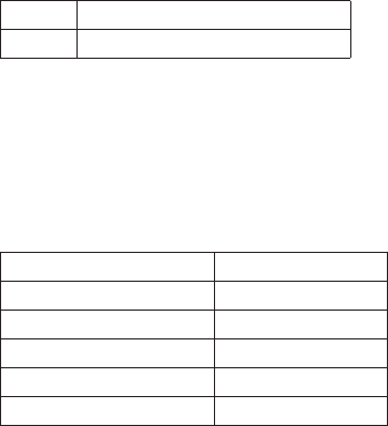
TXO Transmitter Carrier On
TXP Transmitter Primary On
NMEA OPERATION
This radio supports NMEA0183 version 3.01.
NMEA Input
If you have difficulty getting your radio to receive data from your GPS receiver, check the
device’s configuration. It should be set to the following parameters:
Baud rate 4800 bps
Data bits 8
Parity None
Stop bits 1
Data amplitude Over 3.0 V
Drive capability Over 10 mA
The radio supports RMC, GLL, GNS, GGA and ZDA sentences. When these sentences are
on the following priority order.
xStatus:RMC > GLL > GNS > GGA
x
xUTC Time: RMC > GLL > GNS > GGA > ZDA
xDate: RMC > ZDA
x
#NOTE 1: If the radio receives only a GLL sentence, the radio does not display the current
speed, course, and date.
#Note 2: If the radio receives both RMC and GLL sentences, the radio uses only the RMC
sentence.
#Note 3: Status data is used to check whether the GPS data is valid or invalid.
NMEA Output
When the radio receives a DSC call (Distress, Position Reply, or Position Send), it outputs a
#NOTE: When the radio receives a distress call, it outputs a sentence in the
following format:
x$CDDSC,12,3081234000,,07,00,0354013946,0657,,,S,E*6D
x$CDDSE,1,1,A,3081234000,00,60875646*13
44

REGULATIONS AND SAFETY WARNINGS
MARITIME RADIO SERVICES OPERATION
WARNING
!
use of the U.S. Coast Guard, use in Canada, and use in international waters. Operation
on these frequencies without proper authorization is strictly forbidden. See the channel
tables beginning on page 50 for a list of available channels and their uses. If you are still
not certain which channels to use, see the FCC maritime radio page at the FCC website
individuals requiring a license, such as commercial users, you should obtain a license
application from your nearest FCC field office (for US users) or Industry Canada (for
Canadian users).
BASIC RADIO GUIDELINES
You should familiarize yourself with the rules on marine radios and be aware of which
rules apply to your boat. Complete guidelines for all ship and marine radio types can be
found at the US Coast Guard website under the topic Radio Info for Boaters (the direct link
affect nearly all boaters.
xIf you have a VHF radio on your boat, you must maintain a watch on channel 16
(156.800 MHz) whenever the radio is not being used to communicate. Effective from
2004, if a radio is carried, it must be turned on and set to channel 16 whenever your
vessel is underway.
xIf you hear a distress call, wait a few minutes to let a shore station or Coast Guard
vessel respond. If no other station has responded after 5 minutes, you must respond to
the distress call.
xDo not make false mayday or distress calls as a prank or to test your radio. (This is
essentially like making a false 9-1-1 call; you may be subject to fines.)
COMPLIANCE
FCC Part 15
The equipment has been tested and found to comply with the limits for a Class B
device, pursuant to Part 15 of the FCC rules. These limits are designed to provide
reasonable protection against harmful interference in a residential installation. This
equipment generates, uses, and can radiate radio frequency energy and, if not installed
and used in accordance with the instructions, may cause harmful interference to radio
communications. However, there is no guarantee that interference will not occur in a
particular installation. If this equipment does cause harmful interference to radio or
television reception, which can be determined by turning the equipment off and on, the
user is encouraged to try to correct the interference by one of the following measures:
xReorient or relocate the receiving antenna.
xIncrease the separation between the equipment and the receiver
45
xConnect the equipment into an outlet on a circuit different from that to which the
receiver is connected.
x
could void your authority to operate the equipment. Any change or modification must be
approved in writing by West Marine.
This device complies with Part 15 of the FCC rules. Operation is subject to the following
two conditions: (1) This device may not cause harmful interference, and (2) this device
must accept any interference received, including interference that may cause undesired
operation.
pourrait annuler le droit à l’utilisateur de faire fonctionner cet équipement. Tout
changement ou modification doit être approuvé par écrit par West Marine.
Avis de conformité à la FCC : Ce dispositif a été testé et s’avère conforme à l’article 15 des
règlements de la Commission fédérale des communications (FCC). Ce dispositif est soumis
2) Il doit pouvoir supporter les parasites qu’il reçoit, incluant les parasites pouvant nuire à
son fonctionnement.
provide at least 7.9 in (20 cm) separation from the human body at all times.
IC
subject to the following two conditions: (1) this device may not cause interference, and (2)
this device must accept any interference, including interference that may cause undesired
operation of the device.
causer d’interférences nuisibles et (2), il doit pouvoir accepter les interférences, incluant
celles pouvant nuire à son fonctionnement normal.
to provide at least 7.9 in. (20 cm) separation from the human body at all times.
installé pour assurer une séparation d’au moins 7.9 in. (20 cm) du corps humain à tout
moment.
46

ANTENNA SELECTION AND INSTALLATION
Your UM385 has been designed to accommodate all of the popular marine VHF antennas.
However, the selection and the installation of the antenna is the responsibility of the user
or installer.
transmitting antennas. Therefore, the antenna used with this radio should be installed
using the following guidelines to ensure a suitable distance between the antenna and
persons close by.
xSmall whip antennas (3 dB) or smaller should be installed keeping at least a two foot
separation distance between the radiating element and people.
xMedium antennas (6 dB) should be installed keeping at least a three foot separation
distance.
xLarger antennas (9 dB) should be installed keeping at least a four foot separation
distance.
xNo person should touch the antenna or come into the separation distance when the
radio is transmitting.
This Limited Warranty is Void outside the United States of America and Canada.
WARRANTOR: UNIDEN AMERICA CORP. (“Uniden”)
ELEMENTS OF WARRANTY: Uniden warrants, for three years, to the original retail owner,
this Uniden roduct to be free from defects in materials and craftsmanship with only the
WARRANTY DURATION: This warranty to the original user shall terminate and be of no
further effect 36 months after the date of original retail sale. The warranty is invalid if
sold by Uniden, (C) improperly installed, (D) serviced or repaired by someone other than
an authorized Uniden service center for a defect or malfunction covered by this warranty,
(E) used in any conjunction with equipment or parts or as part of any system not manufac-
tured by Uniden, or (F) installed or programmed by anyone other than as detailed by the
Operating Guide for this product.
STATEMENT OF REMEDY: In the event that the product does not conform to this warran-
ty at any time while this warranty is in effect, warrantor will either, at its option, repair
or replace the defective unit and return it to you without charge for parts, service, or any
connection with the per-formance of this warranty. Warrantor, at its option, may replace
the unit with a new or refur-bished unit. THE LIMITED WARRANTY SET FORTH ABOVE IS
THE SOLE AND ENTIRE WARRANTY PERTAINING TO THE PRODUCT AND IS IN LIEU OF
TO ANY IMPLIED WARRANTIES OF MERCHANTABILITY OR FITNESS FOR A PARTICULAR
PURPOSE. THIS WARRANTY DOES NOT COVER OR PROVIDE FOR THE REIMBURSEMENT
47
OR PAYMENT OF INCIDENTAL OR CONSEQUENTIAL DAMAGES. Some states do not allow
other rights which vary from state to state. This warranty is void outside the United States
of America.
PROCEDURE FOR OBTAINING PERFORMANCE OF WARRANTY: If, after following the
instructions in this Operating Guide you are certain that the Product is defective, pack the
Product carefully (preferably in its original packaging). Include evidence of original pur-
chase and a note describing the defect that has caused you to return it. The Product should
be shipped freight prepaid, by traceable means, or delivered, to warrantor at:
Uniden America Corporation
743 Henrietta Creek Rd., Suite 100
48
49
50
51

U01UT656ZZA(0)
QUESTIONS?
Visitez notre site web au
www.uniden.com.
Imprimé en Vietnam
QUESTIONS?
Visit our website at
www.uniden.com.
Printed in Vietnam