Uniform AG1311 Contactless Smart Card Reader Module User Manual
Uniform Industrial Corp. Contactless Smart Card Reader Module Users Manual
UserManual.wiki
>
Uniform
>
AG1311 User Manual
Users Manual
Navigation menu
Upload a User Manual
Namespaces
Wiki Guide
HTML
PDF
Info
Views
User Manual
Discussion / Help
Navigation
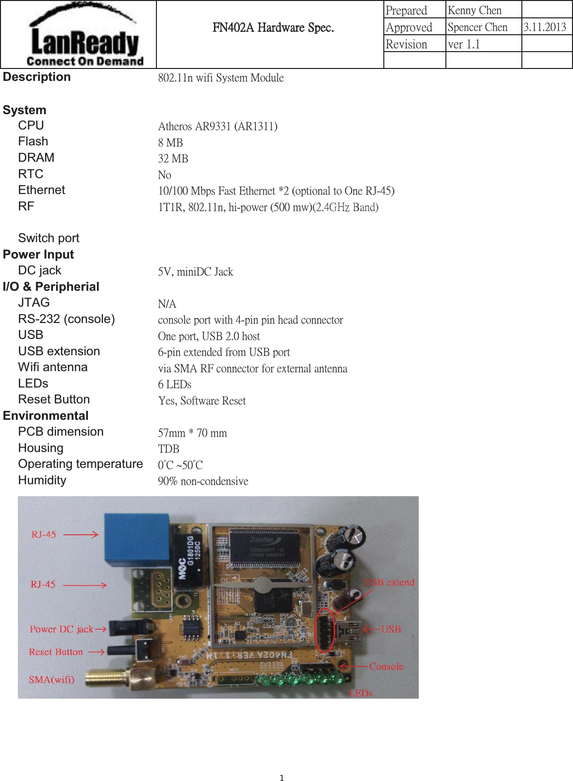
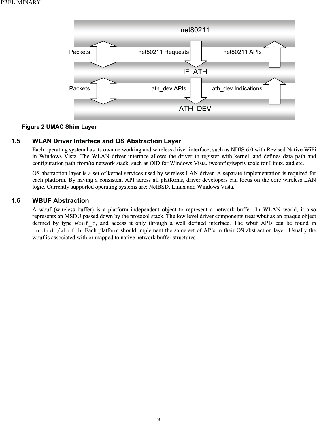
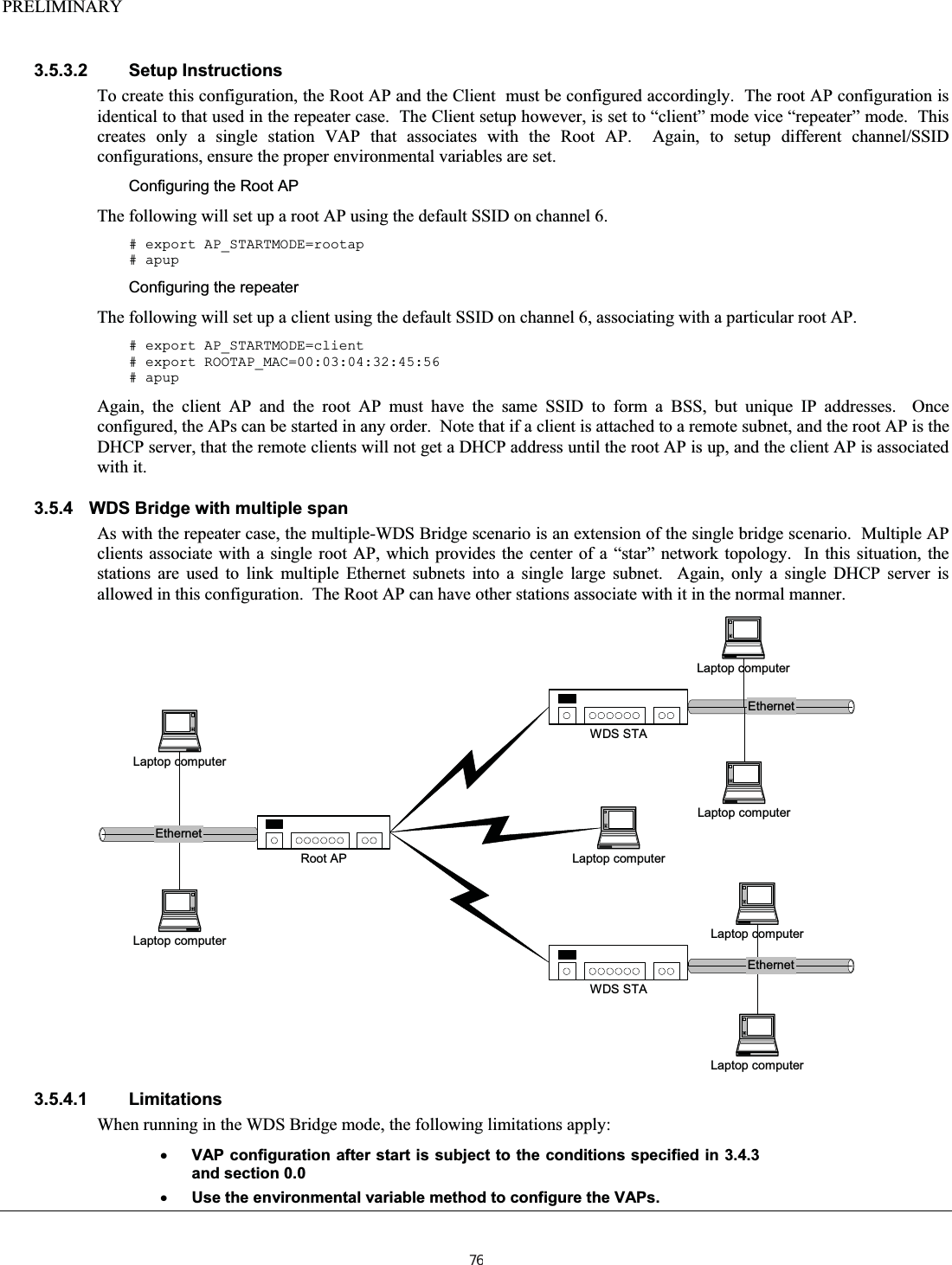
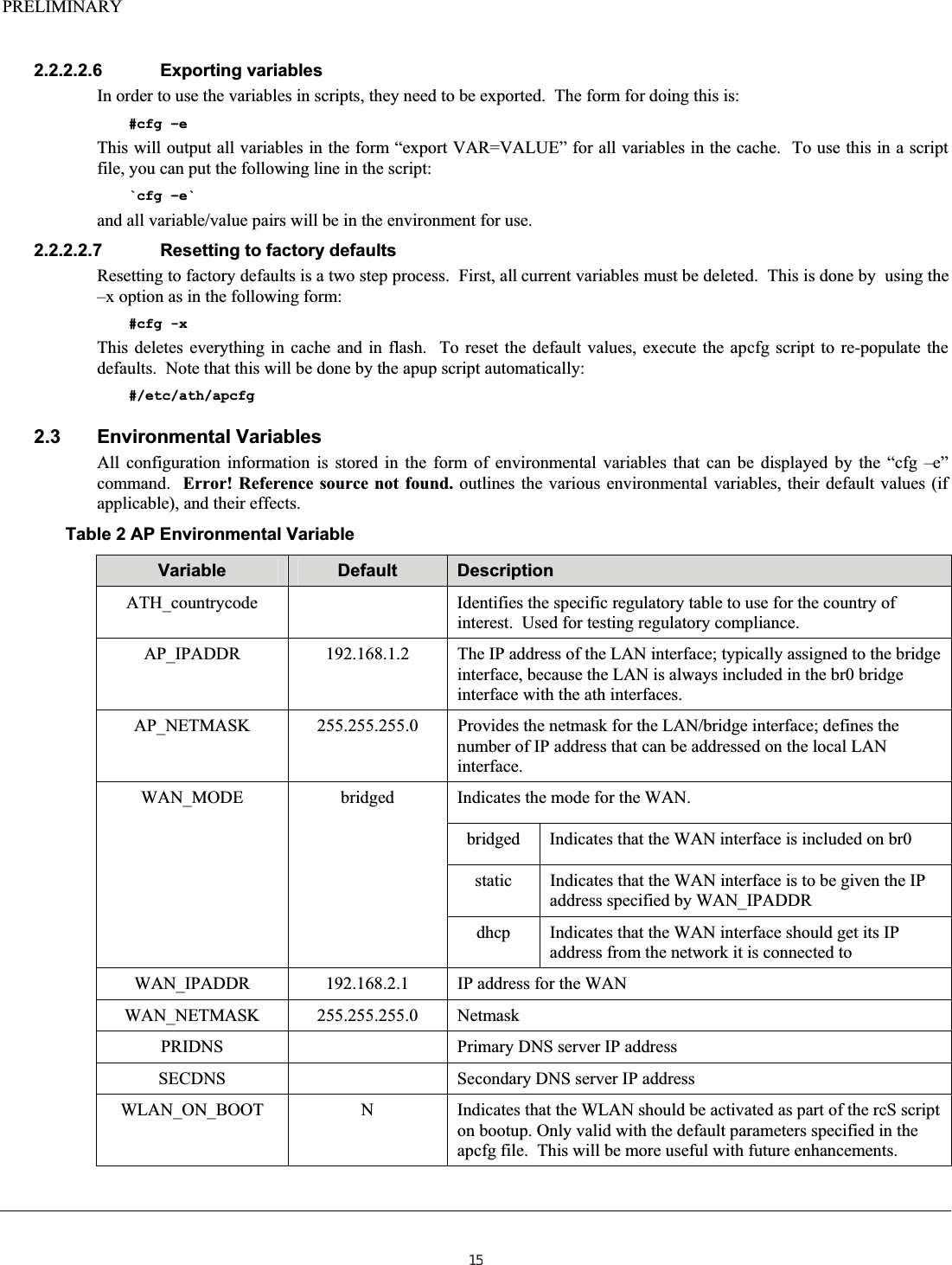
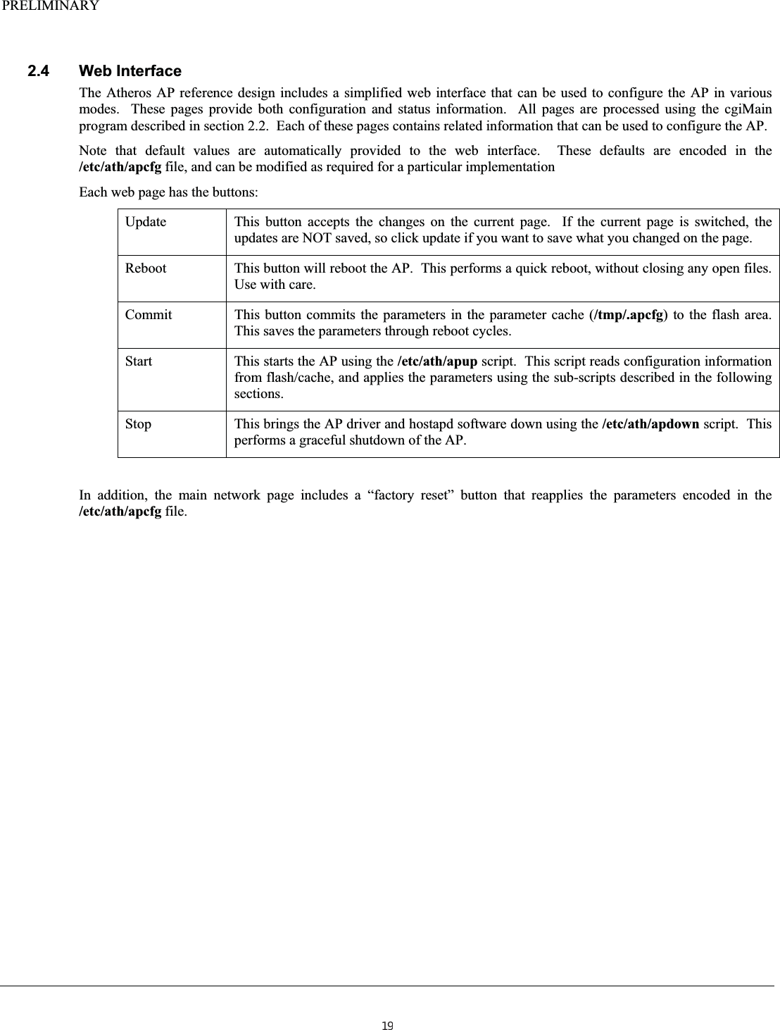
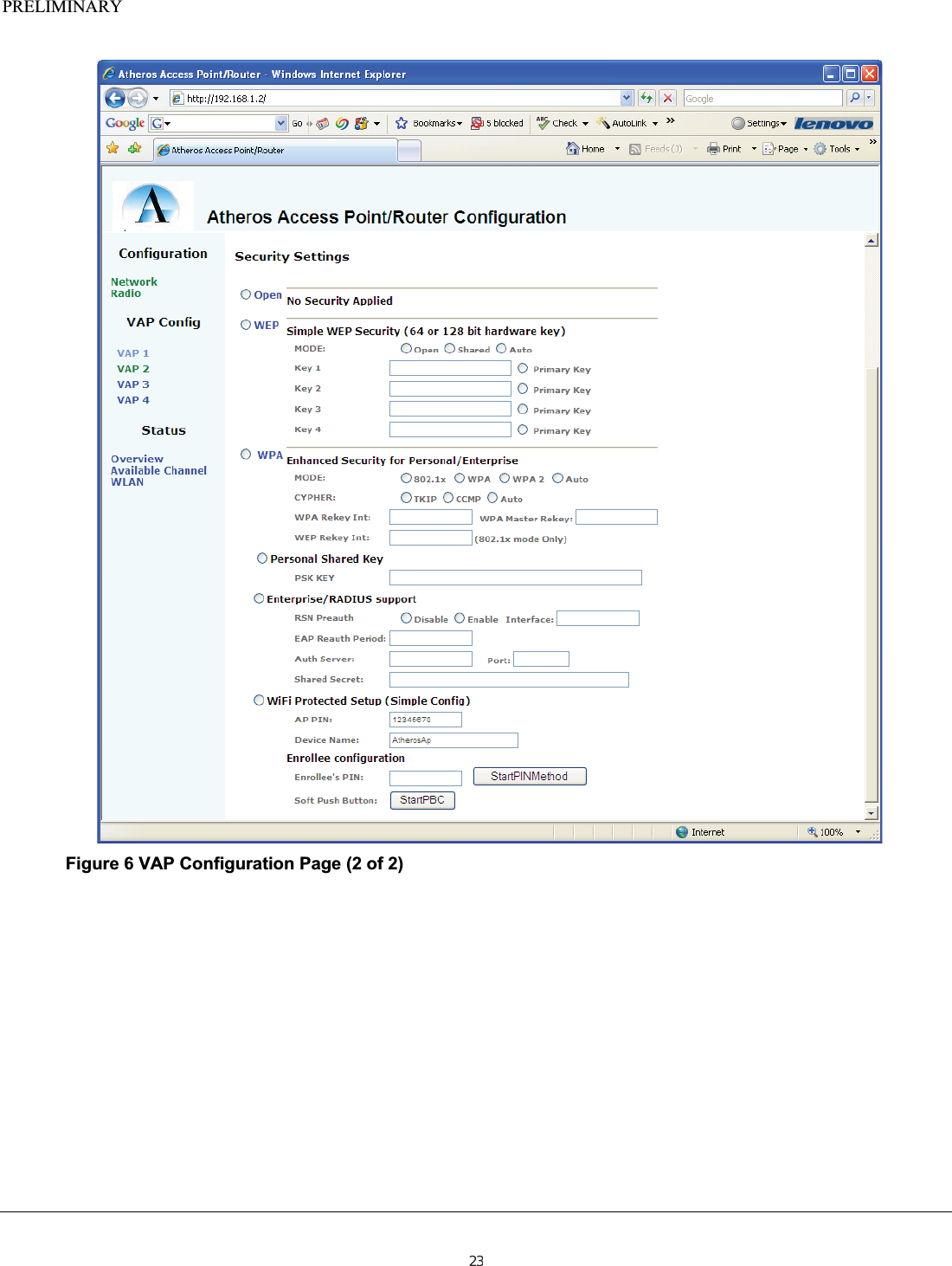
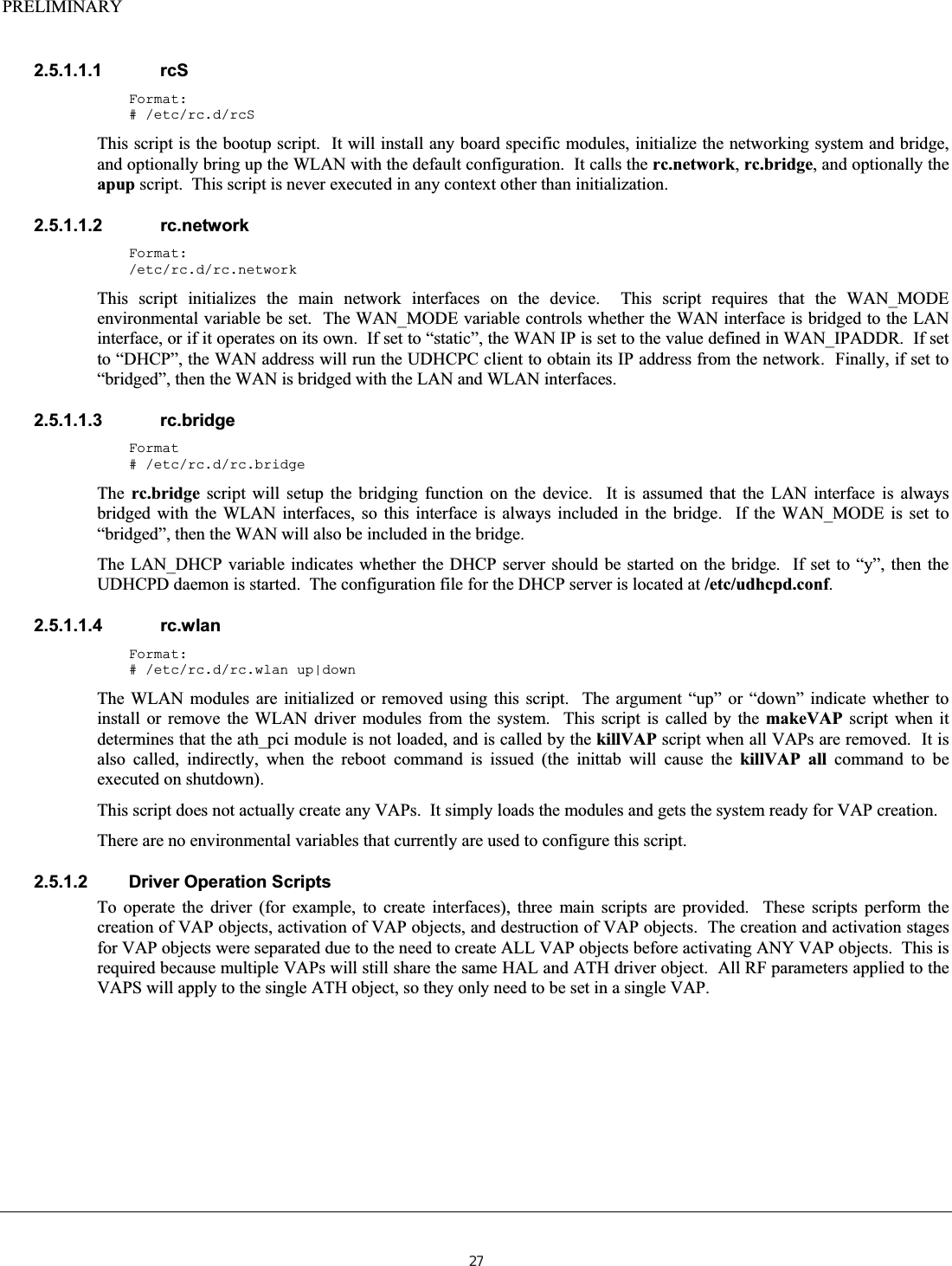
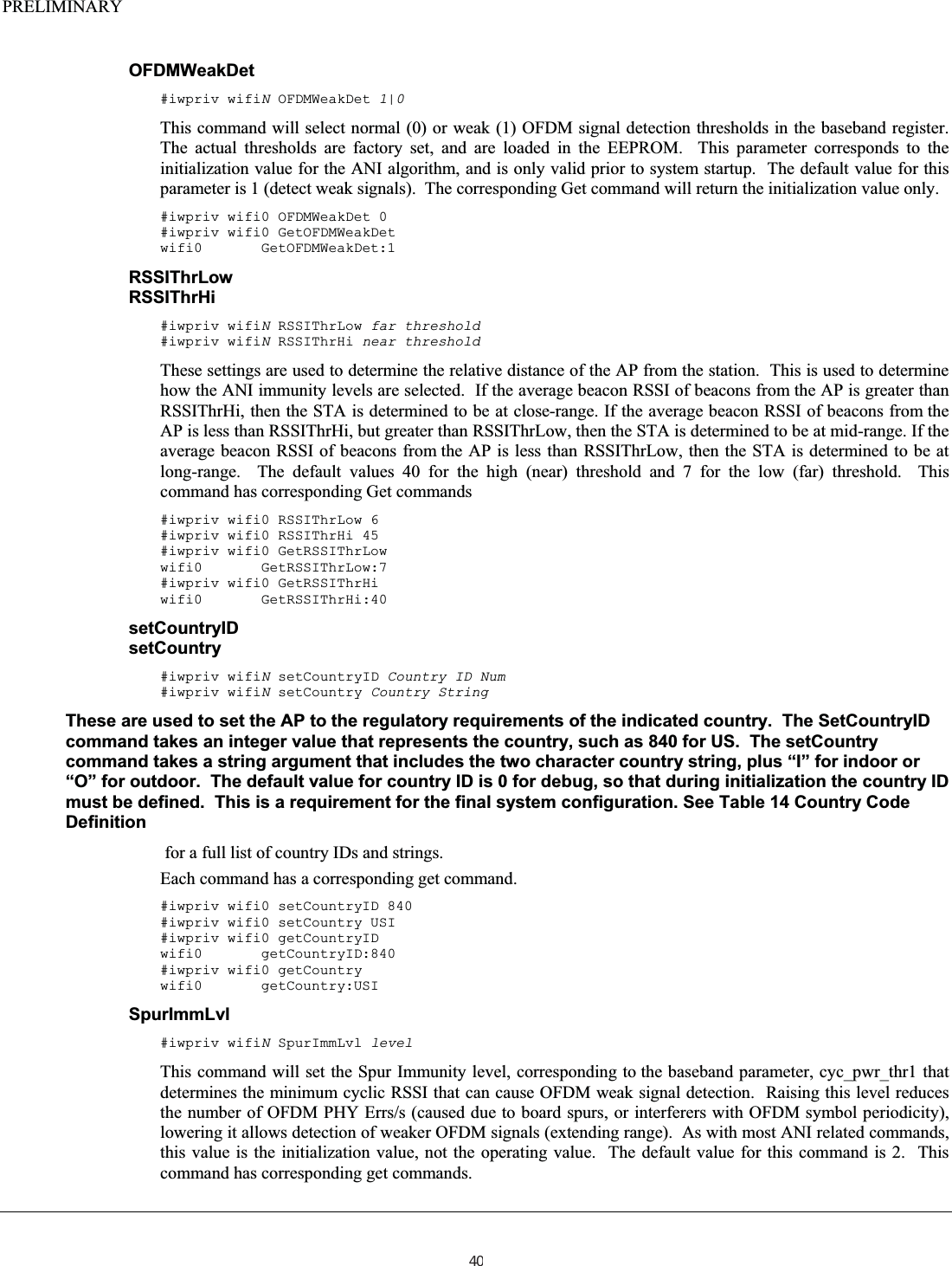
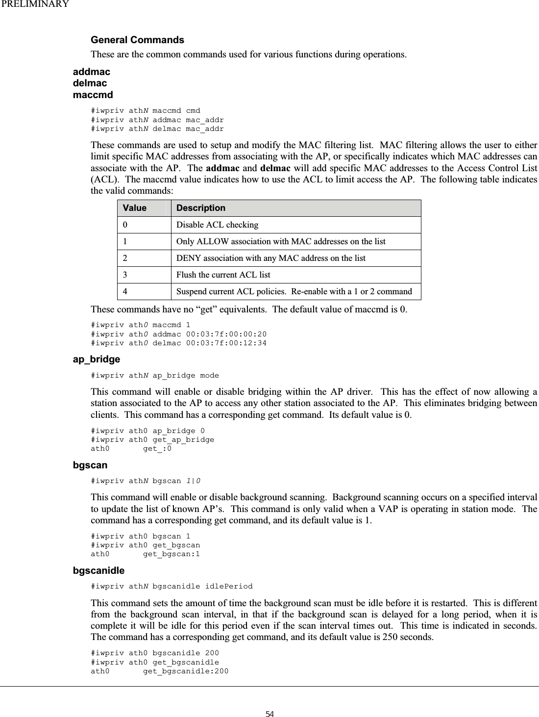
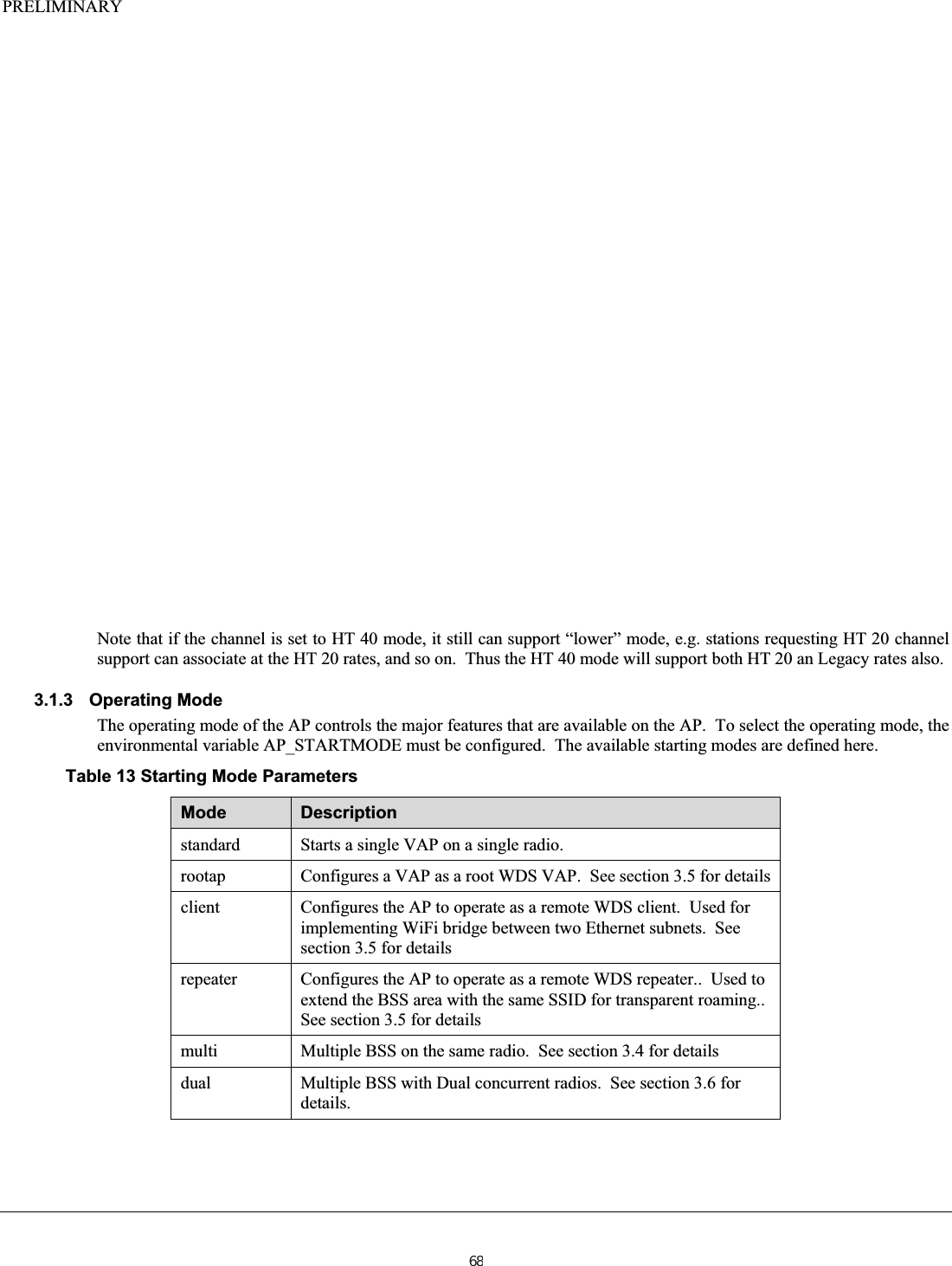
![PRELIMINARY2.2.1.3 Flash Usage This program seeks to eliminate extra usage of flash resources by using an existing sector for storing date (the calibration sector). Note that the board and radio calibration data only take up the first 32 KB of flash storage, leaving the second 32 KB available. The permanent storage area for parameter data is put into this area without using a filesystem – the data is simply written to flash as a linear string of data. Parameters are stored in the “NAME=VALUE” format. The first 4 bytes of the data are flagged with a know value (0xfaf30020) as a synchronization value to verify the data is valid (as opposed to an “erased” flash). The data is assumed terminated if a value of 0x0 is found (note that all data is stored as ASCII, and can be read/edited in flash using u-boot). A limit of 32 characters for variable names, and 64 characters for values are imposed. Adding the “=” and the <lf> terminators, each value has a maximum of 98 characters used. This means that a total number of (32768-4)/98 = 334 parameters can be stored in this area. Since many parameter names and values are much shorter, an estimate of 450-500 parameters is not unreasonable. Note that parameters will only take up the space required, not the full 32/64 byte area. The following is an example “dump” of the parameter data in flash: ar7100> md 0xbf668000 bf668000: faf30020 49504144 44523d31 39322e31 ... IPADDR=192.1 bf668010: 36382e31 2e320a49 504d4153 4b3d3235 68.1.2.IPMASK=25 bf668020: 352e3235 352e3235 352e300a 57414e49 5.255.255.0.WANI bf668030: 503d3139 322e3136 382e322e 310a5741 P=192.168.2.1.WA bf668040: 4e4d4153 4b3d3235 352e3235 352e3235 NMASK=255.255.25 bf668050: 352e300a 41505f53 5349443d 41503234 5.0.AP_SSID=AP24 bf668060: 5f486f6c 64656e0a 41505f53 5349445f _Holden.AP_SSID_ bf668070: 323d4150 35305f48 6f6c6465 6e0a4150 2=AP50_Holden.AP bf668080: 5f504153 53504852 4153453d 6672617a _PASSPHRASE=fraz bf668090: 65310a41 505f5041 53535048 52415345 e1.AP_PASSPHRASE bf6680a0: 5f323d66 726f7a65 0a5a4849 46454e47 _2=froze.ZHIFENG bf6680b0: 3d686572 650a0000 0000fbb7 ffc1f6f7 =here........... 2.2.1.4 Cache File For temporary changes, a cache file is located in /tmp/.apcfg. This file contains the same type of information that is in the flash, but is not permanent. This is used to perform updates to parameters during a run, but it is not desired to commit these changes to flash. Note that a specific commit operation is required to update the flash area. 2.2.2 Tool Usage The intended use for this is for both a web server interface, and for script access to permanent variables. Having a single program to perform this function will save on flash space. 2.2.2.1 Web Server Usage HTML files that define web pages usually contain static content, unless they have embedded java code. In order to get dynamic content (without using something like PHP or java) something is required to modify the pages such that they display the dynamic data as required. This is accomplished by linking the page name to the cgiMain program. A web server will execute programs/scripts as part of the Computer Gateway Interface (CGI). This allows a program to be run to generate the web page content as required. This interface is exploited for this function. The Busybox httpd daemon will execute as a CGI program any page that is located in the /usr/www/cgi-bin directory. In order to have separate pages that reference the same program, the same method that Busybox uses is used here. Page names are soft linked to /usr/www/cgi-bin/cgiMain. The cgiMain program uses the argv[0] (the name of the program) to determine which html page to process to produce the web content. This works in the exact same way as the file translation mode of the cgiMain program, changing tagged values into their value strings, or in special cases indicating which parameters have been “set” to specific values. 12](https://usermanual.wiki/Uniform/AG1311/User-Guide-2120934-Page-12.png)
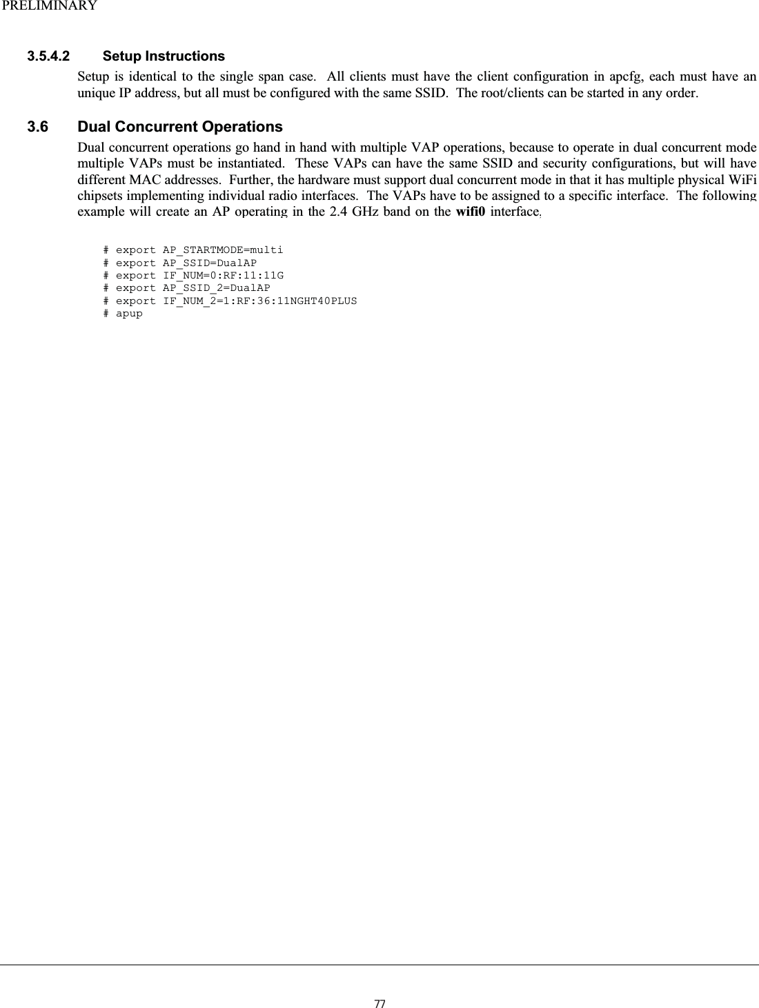
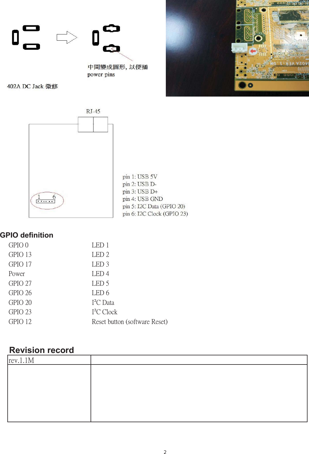
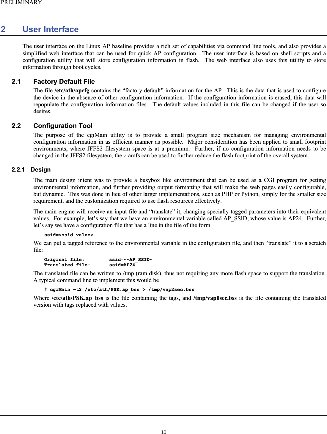
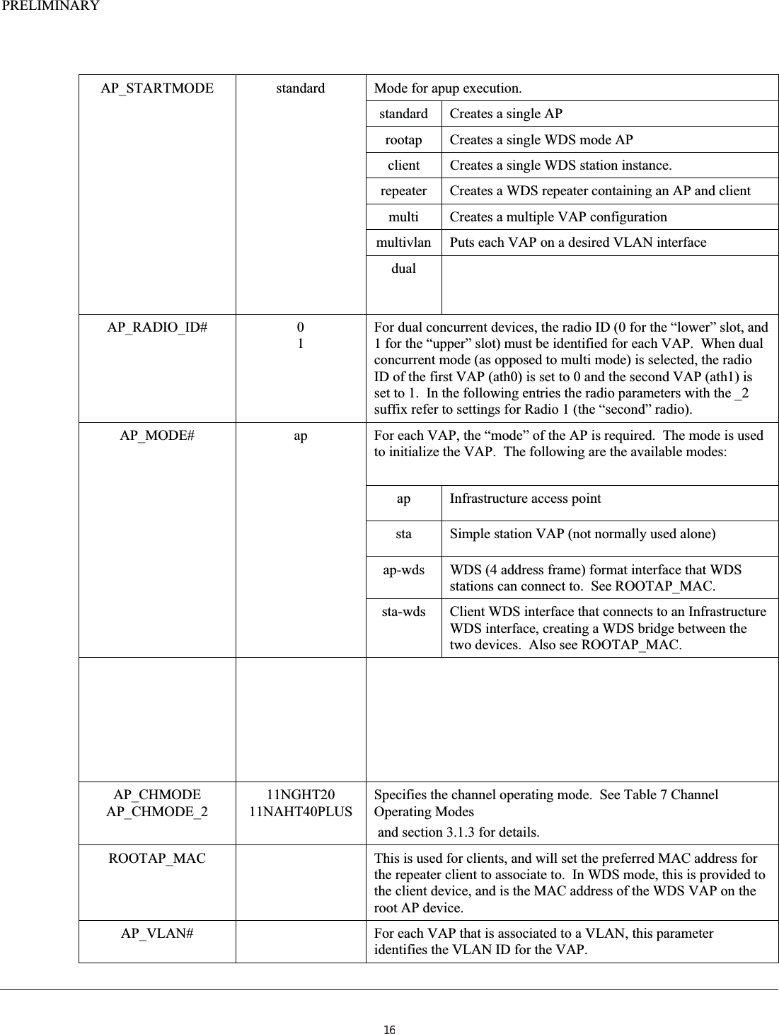
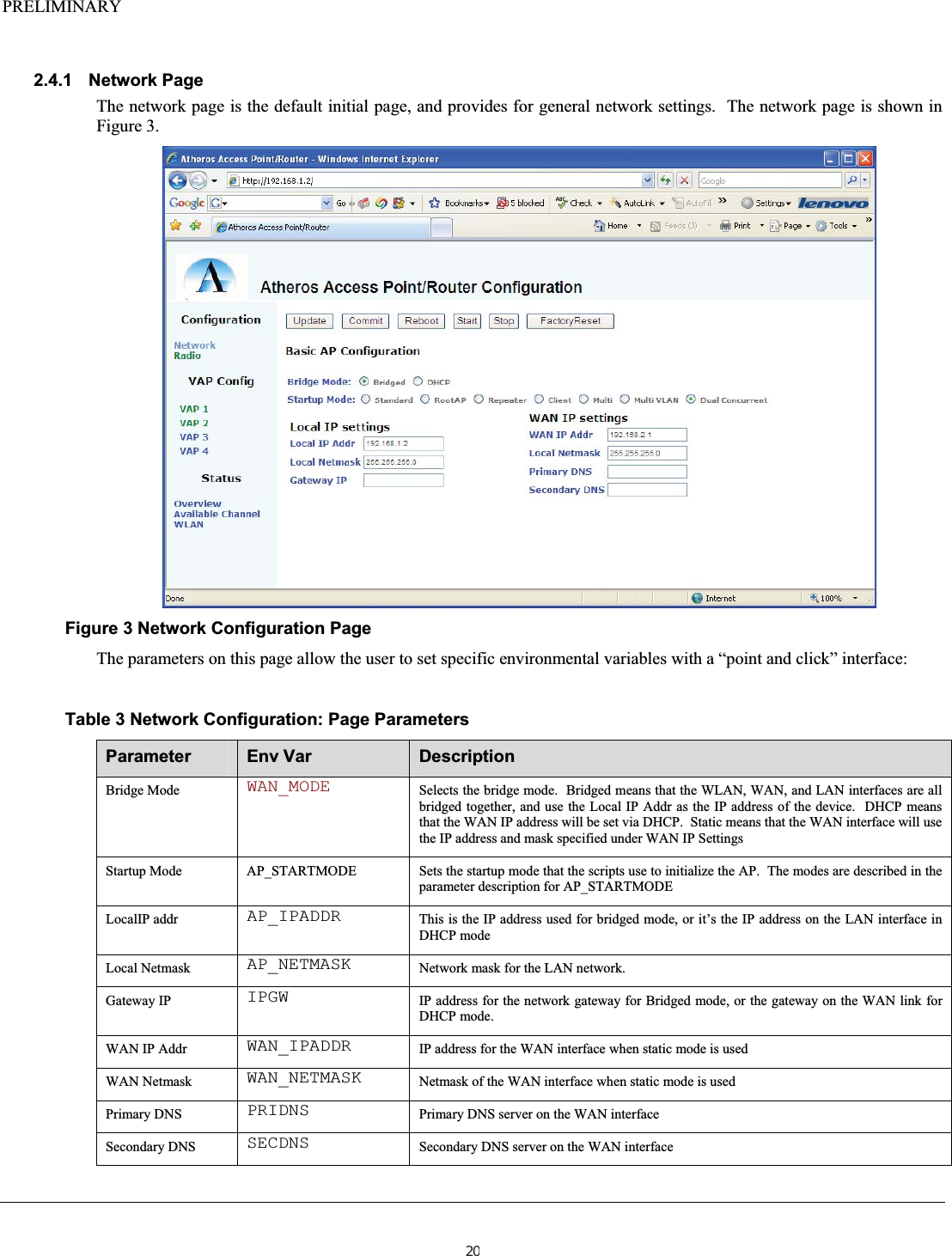
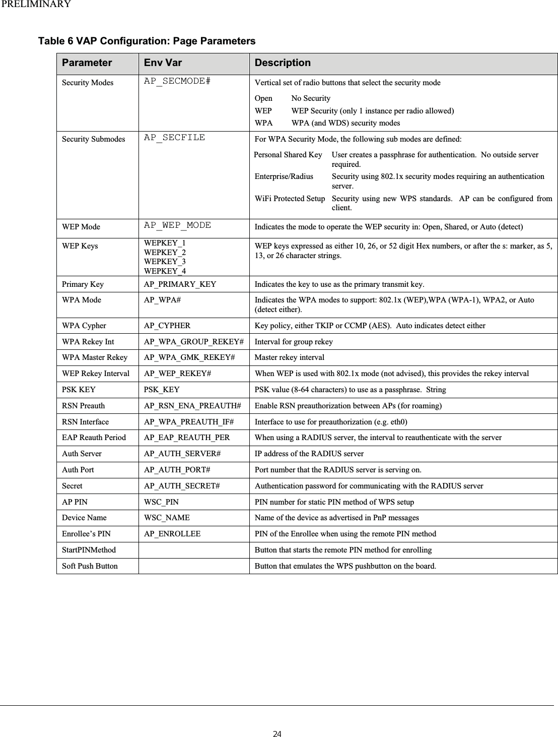
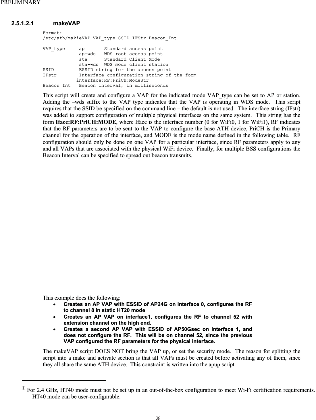
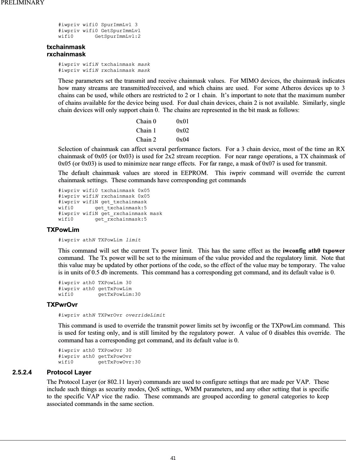
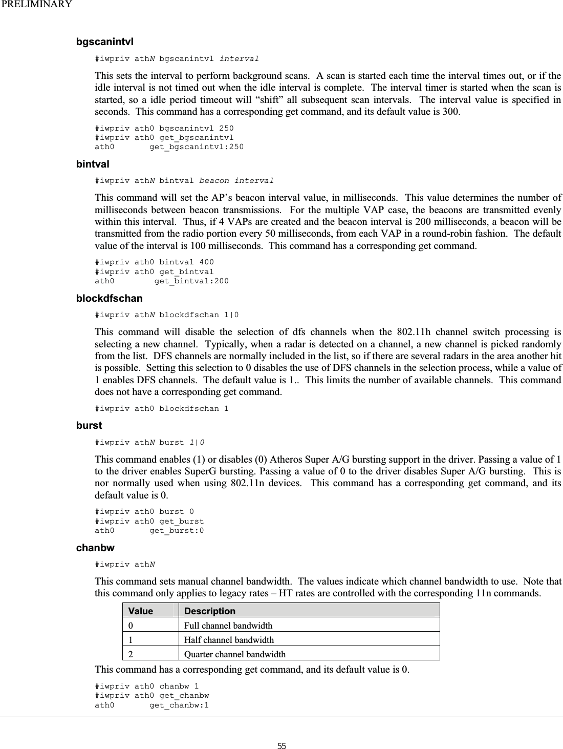
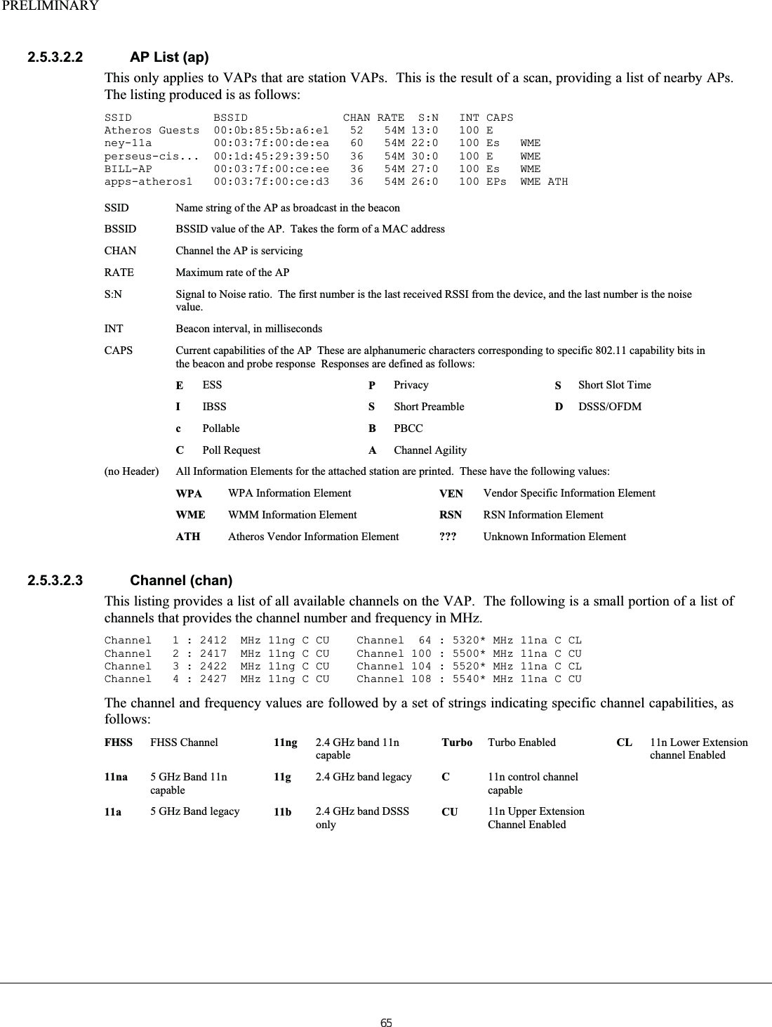
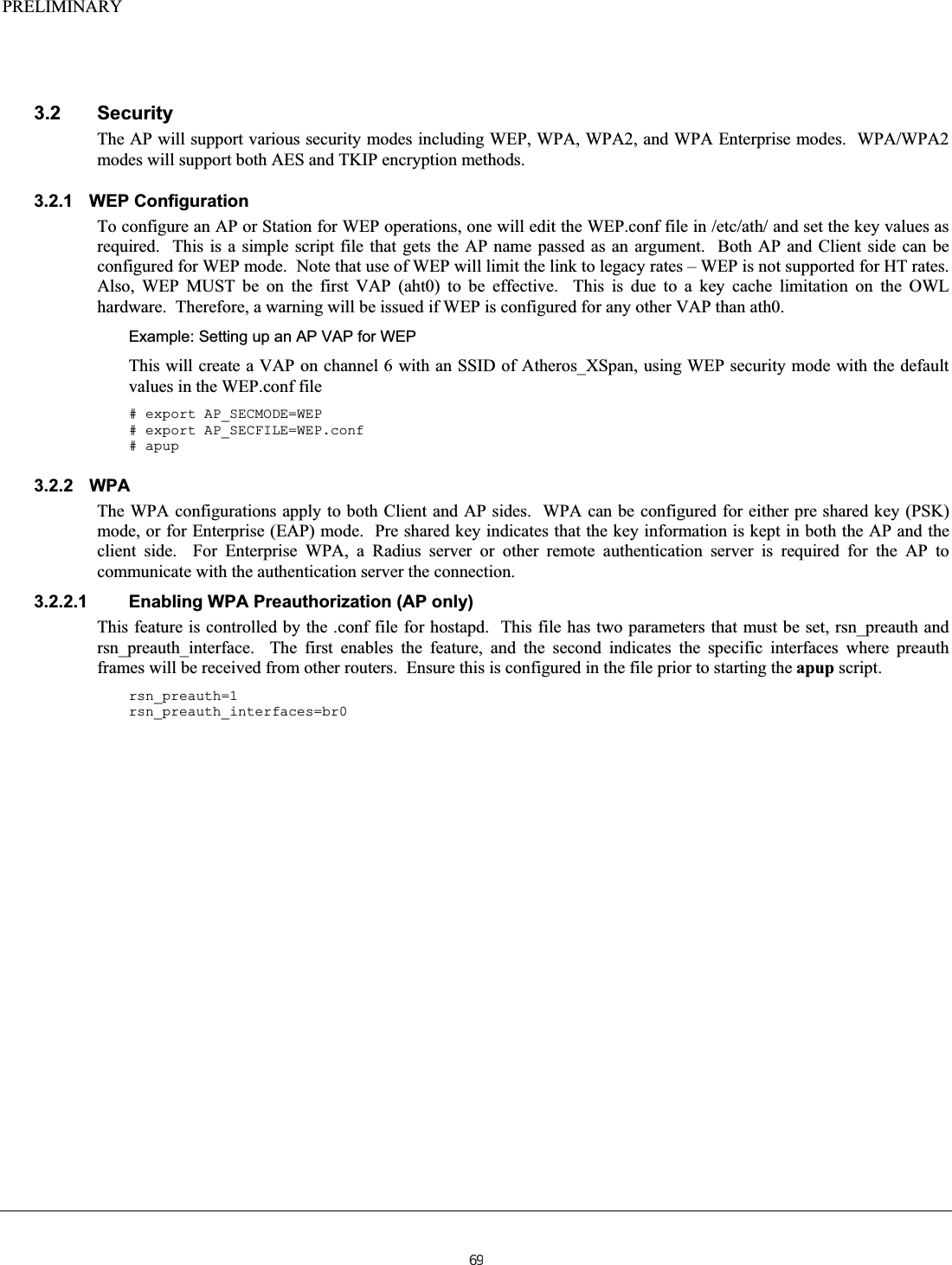
![PRELIMINARY 2.2.2.2 Command Line Usage The cgiMain program also has command line switches available for use in scripts. This provides convenient access to stored parameter data, and data updated via web pages. In fact, a web page can start a script as part of a CGI interface, where the script executes command line versions of cgiMain within the script to perform various functions. Note that the cache file takes precedence over the flash contents when executing scripts. This is to allow changes to be made and executed on a temporary basis, and only kept if the desired configuration operates satisfactorily. If you want to discard cache change, they either ALL have to be discarded, or specific parameters removed. See adding, deleting, committing, and invalidating cache. In order to avoid putting /usr/www/cgi-bin into the execution path, a soft link from /bin/cfg to /usr/www/cgi-bin/cgiMain can be made. All following examples assume the system is configured in this manner. The basic command line format is as follows: #cfg [option] [option parameter] 2.2.2.2.1 Adding/modifying a variable in the cache file To add a variable/value pair to the cache, use the following form: #cfg –a VAR=VALUE The variable name must not include spaces, and if the value includes spaces they must be “escaped” (\<char>) or the value enclosed in quotes (“val”). 2.2.2.2.2 Deleting (removing) a value from the cache file To delete a variable/value pair from the cache, use the following form: #cfg –r VAR The variable name must not include spaces. If the variable does not exist, no error is generated, but no action is preformed on the cache file. If you remove a variable from the cache file, but do not commit the cache, it will remain in the permanent flash storage and will be defined upon next bootup. 2.2.2.2.3 Committing the cache file to flash To commit the contents of the cache file to flash, use the following form: #cfg –c This copies the entire contents of the cache file to flash. These values will be preserved through boot and power cycles. 2.2.2.2.4 Invalidating the cache file In order to invalidate the cache file (re-read it from flash), use the following form: #cfg –i This re-reads the contents of the flash and overwrites the cache file with the flash values. This effectively eliminates any changes made to the cache file without saving them to flash. Use with caution. 2.2.2.2.5 Translating a file In order to translate a tagged file into a file with values inserted, use the following form: #cfg –t<index> <filename> This performs the translation as defined above. Note that the output is put to stdout, so it must be redirected to the desired destination. The index argument on the option indicates the index value to use for variables with the “#” tag. An example of usage: #cfg –t2 /etc/wpa2/open_bss.ap > /tmp/sec2.cfg This will translate the file /etc/wpa2/openbss.ap, inserting tags and using the value of “_2” as the substation for “#” tags, and output the file to /tmp/sec2.cfg. The original file is not affected. 14](https://usermanual.wiki/Uniform/AG1311/User-Guide-2120934-Page-14.png)
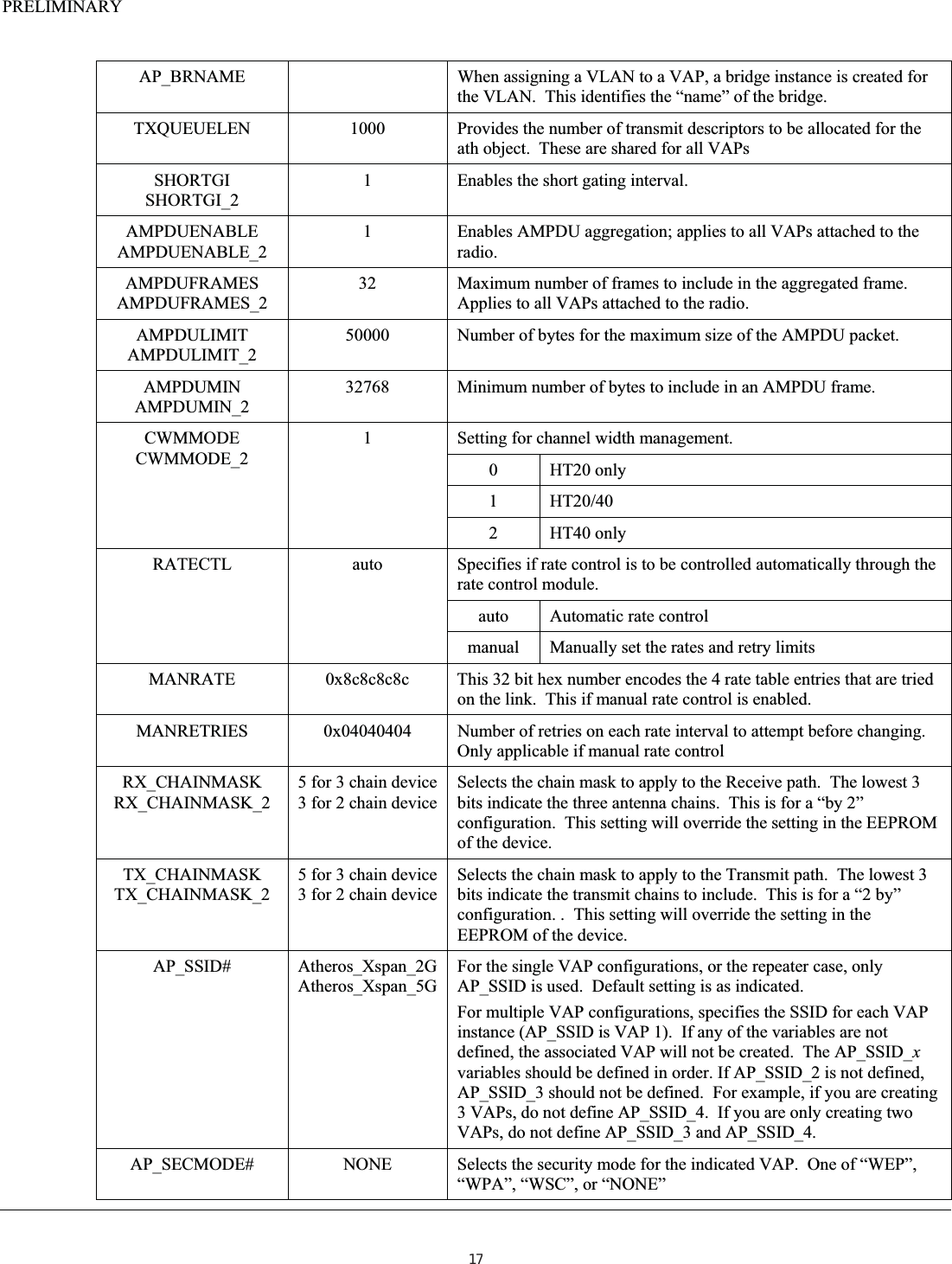
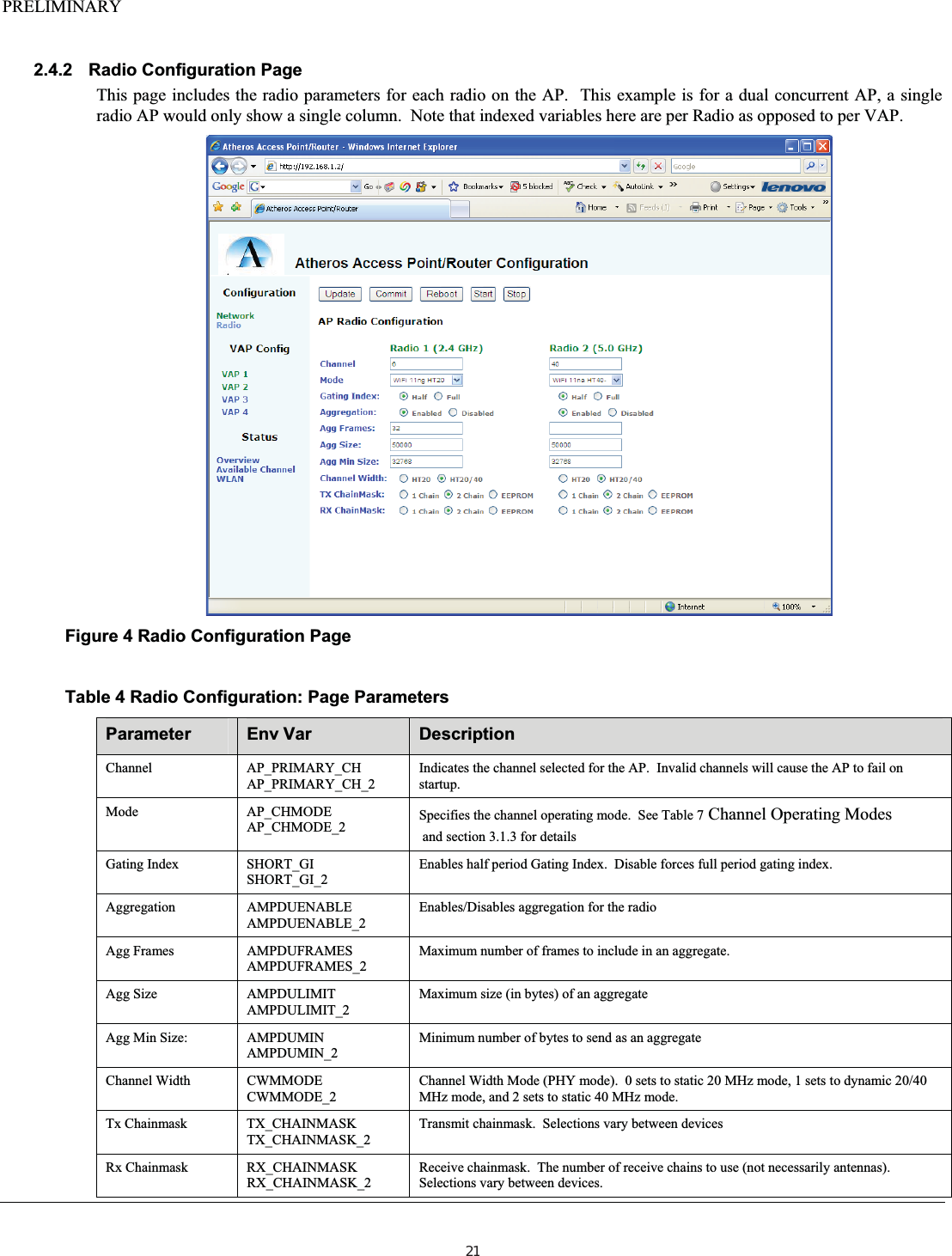
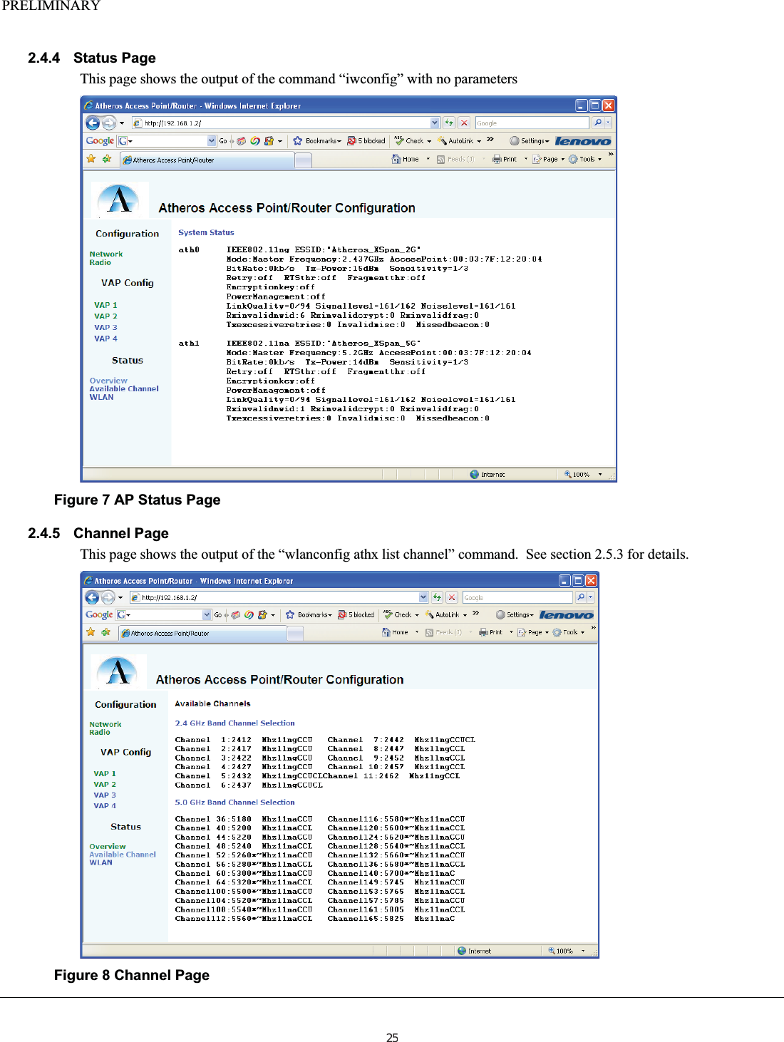
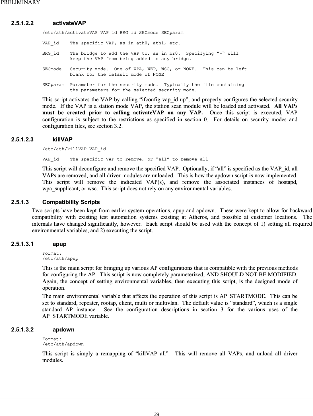
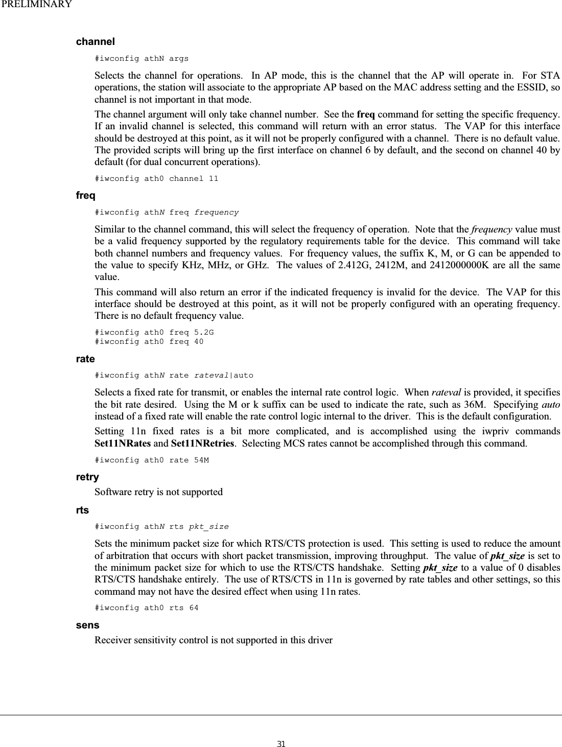
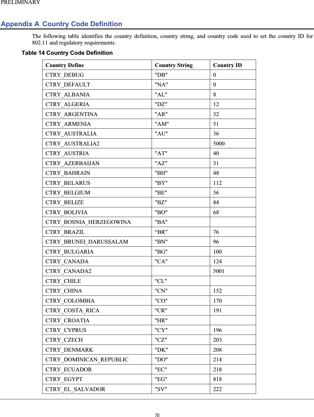
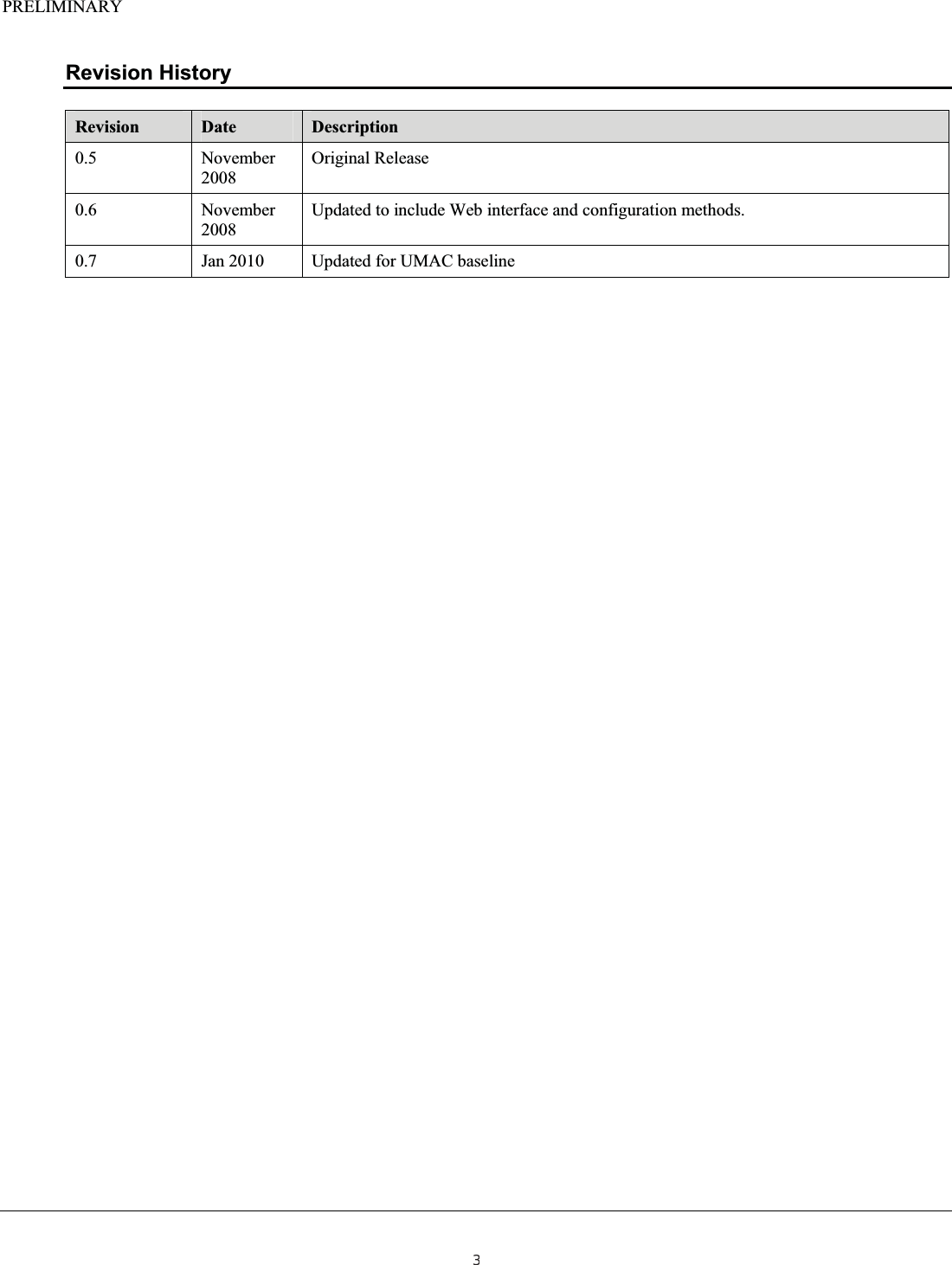
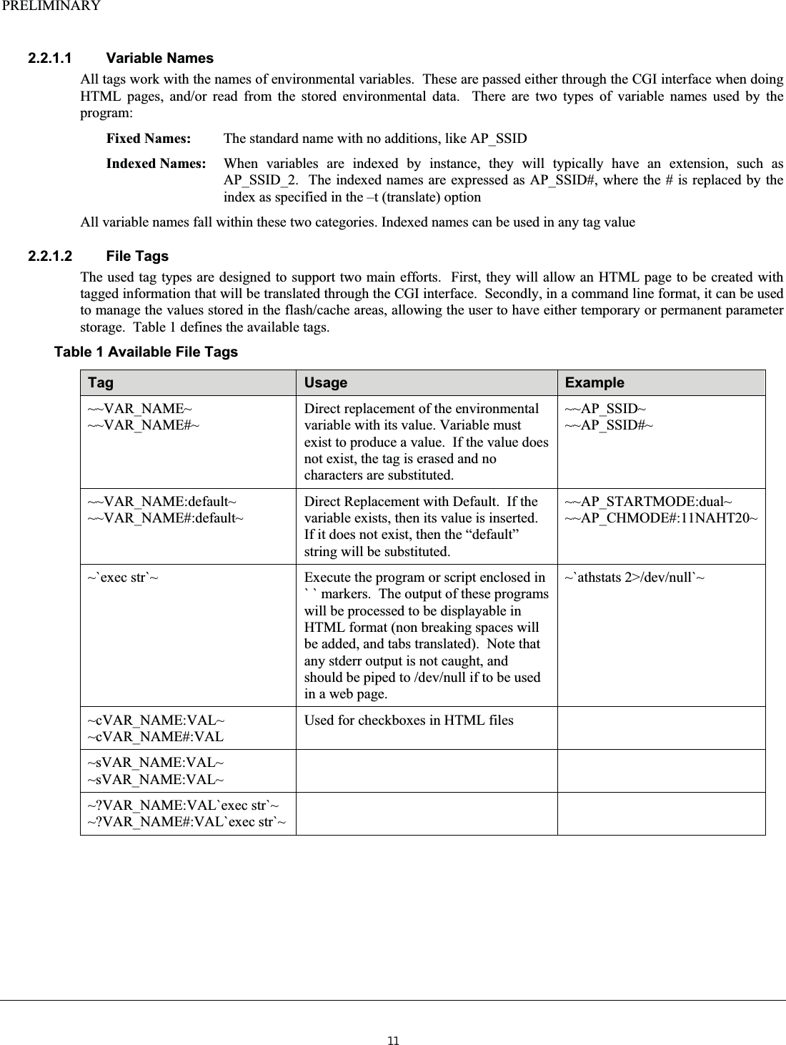
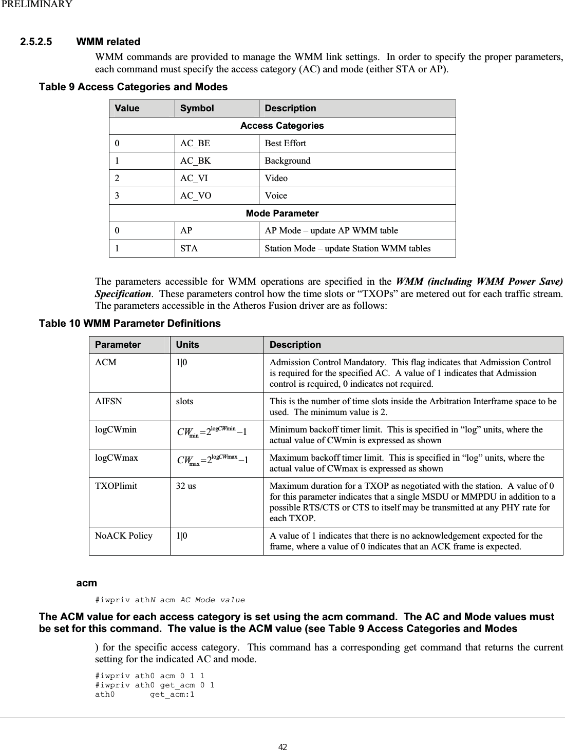
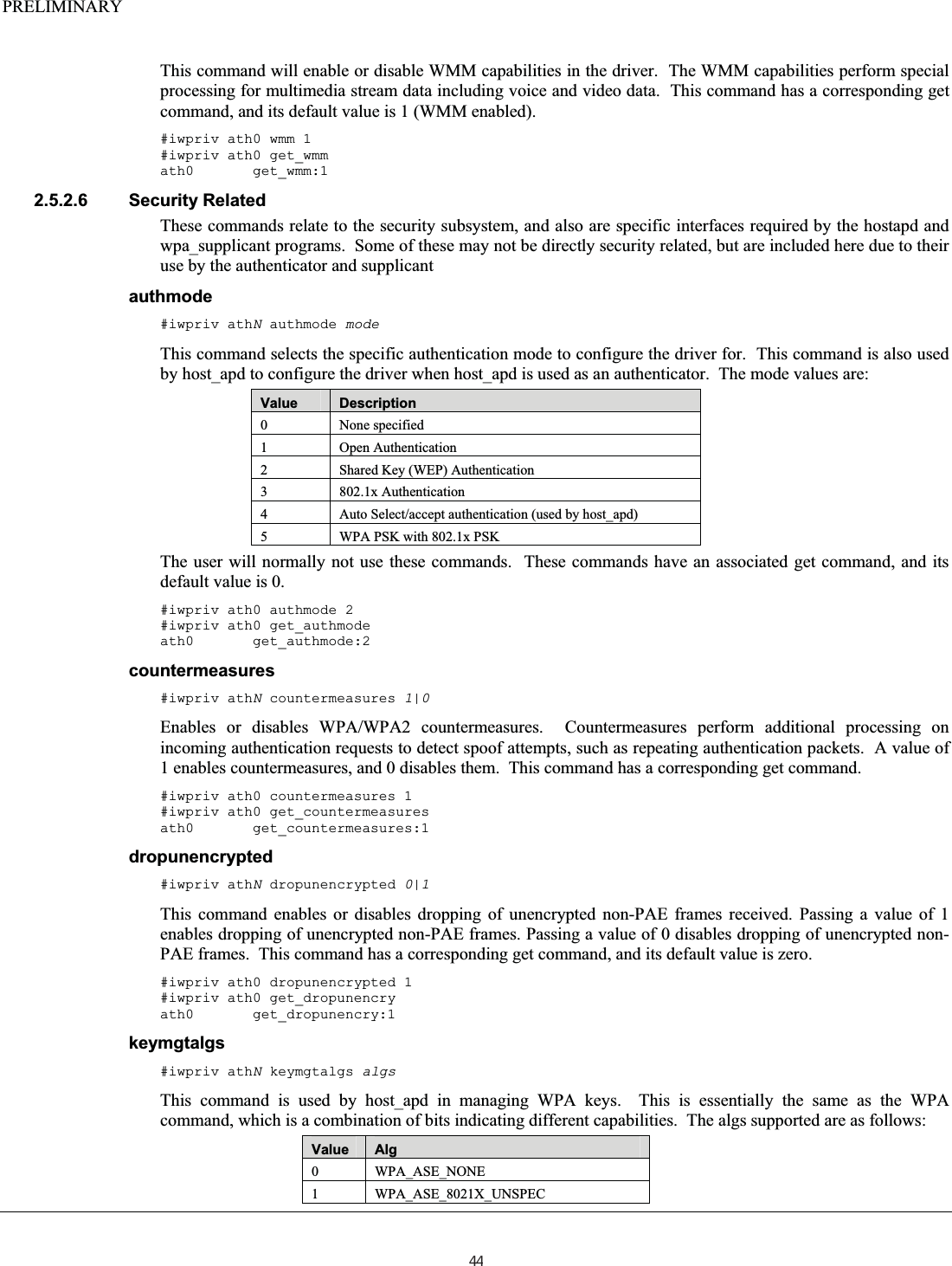
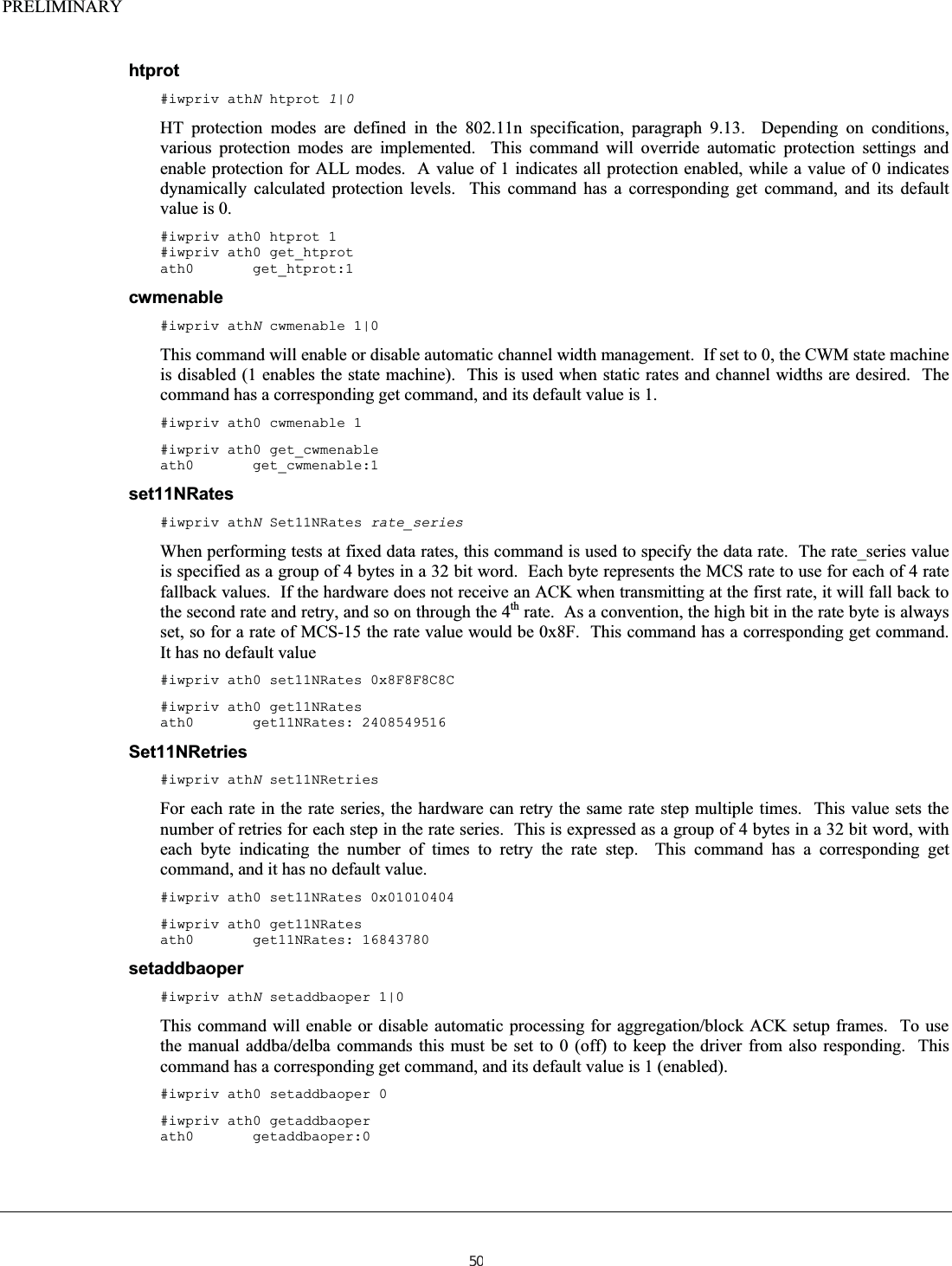
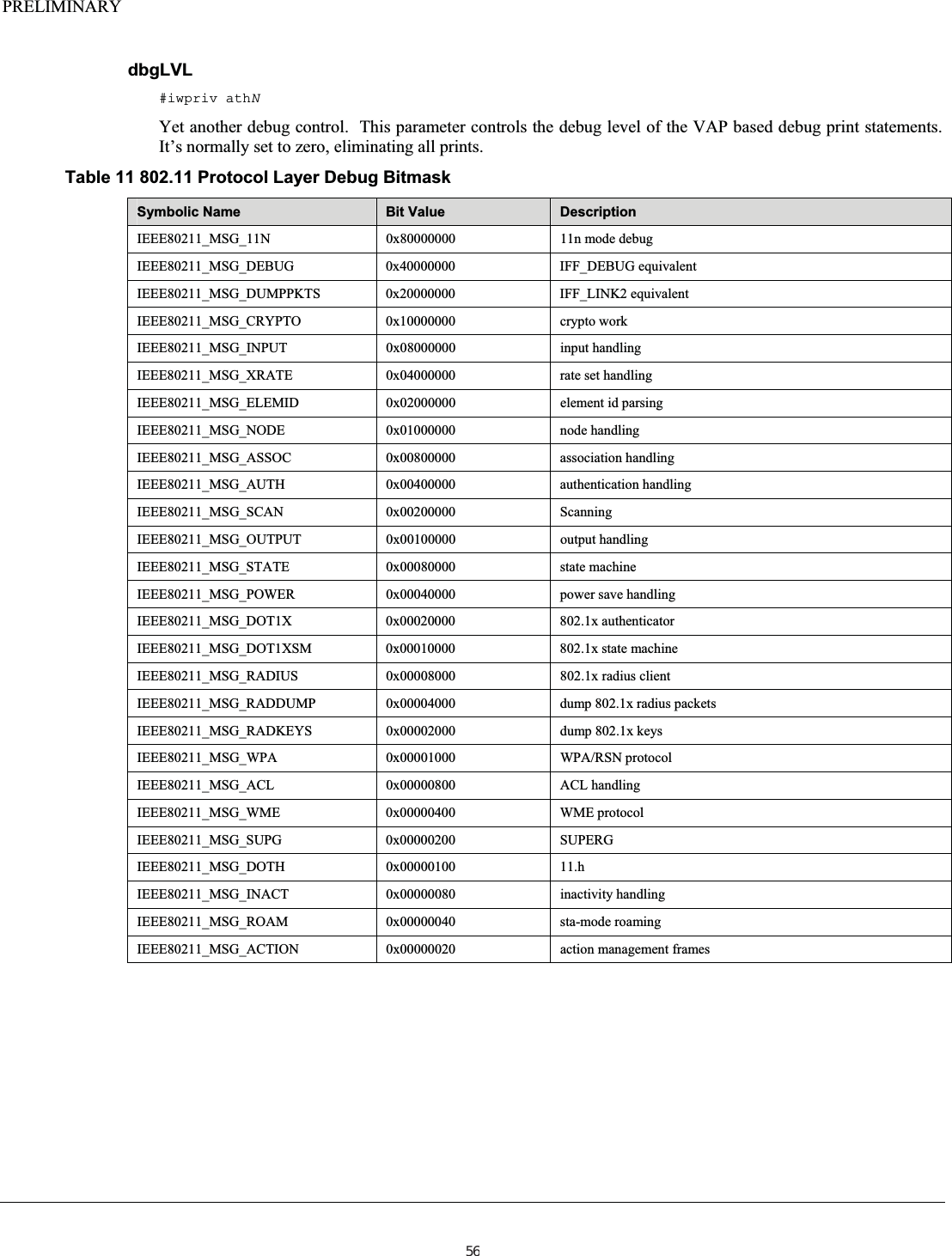
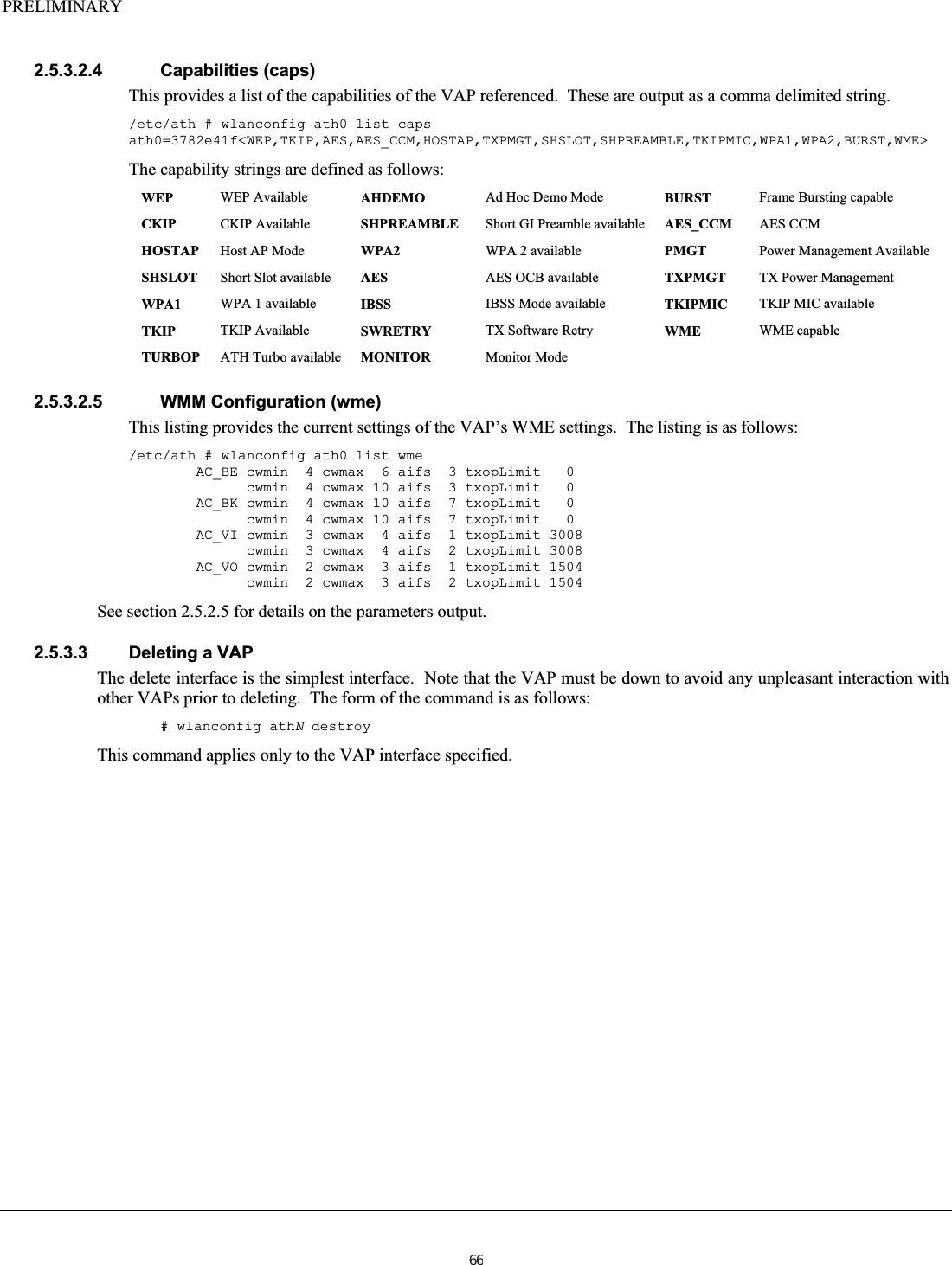
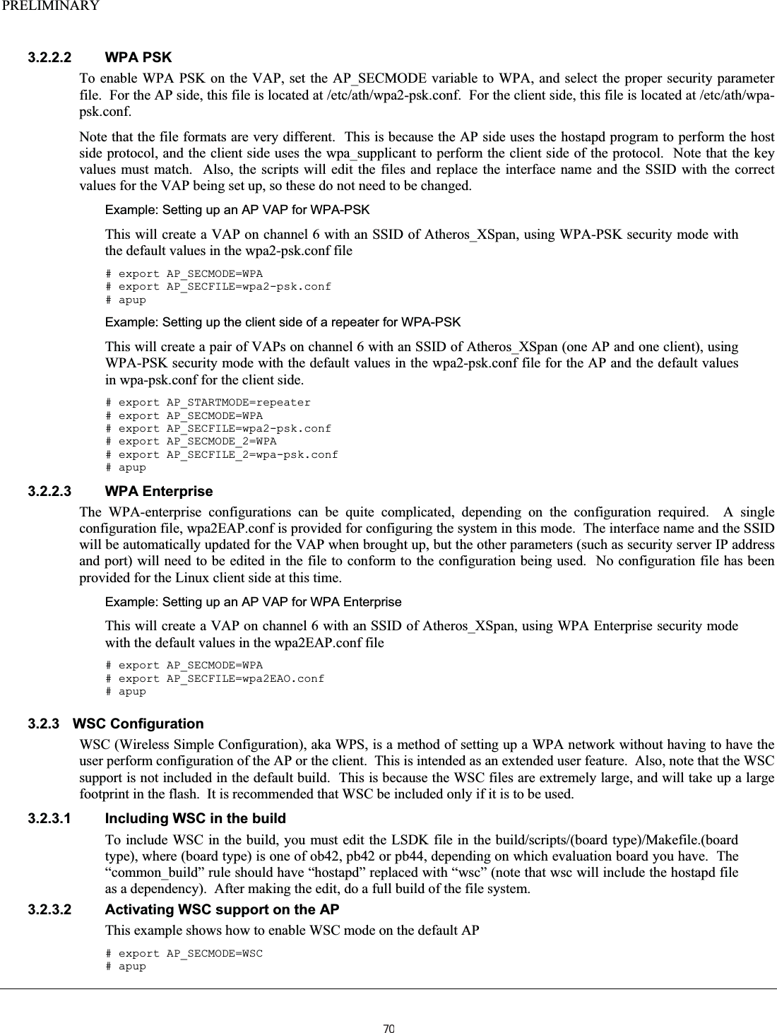
![PRELIMINARY txpower #iwconfig athN txpower power_settingThis command will set the transmit power for all packets on the device. This power is limited by the regulatory limits encoded into the driver, and selected by setting the country code (see iwpriv command setCountry). The value of power_setting is provided in units of dBm. Setting the power_setting value to off will enable the internal power control logic for setting power level. Default Tx power levels are dependant on the information in the selected regulatory table. #iwconfig ath0 txpower 30 enckey #iwconfig athN key [index]key_valueThe commands enc and key are synonyms for the same command to set and manage WEP keys. The hardware will support up to four WEP keys per radio module. The optional index value indicates which key is being set/activated. The index value can be from 1 to 4. The key_value parameter can be specified in either hex mode or as an ASCII string. Key values can be specified for either WEP 64 (40) bit mode, requiring 5 bytes, or WEP 128 (108) bit mode, requiring 13 bytes. In hexadecimal mode this comes out to 10 or 26 hex digits, respectively. Hex digits are separated in groups of 4 by hyphens. When specifying ASCII keys, the keys will require 5 or 13 characters, respectively. All ASCII key strings are preceded by the s: indicator. To turn WEP off, use the off command without index. WEP is automatically turned on when a key is specified. Specifying a key index without a key value will select that key as the active key. #iwconfig ath0 key [2] DEAD_BEEF_EA #iwconfig ath0 key [1] s:AnASCIIkeyVal #iwconfig ath0 key off 2.5.2.2 iwpriv The following section defines all of the iwpriv commands available for each layer. Note that there are some duplicate commands between the layers. It is recommended to use the radio layer commands over the protocol layer command (wifiN commands over athN commands) when duplication exists. 32](https://usermanual.wiki/Uniform/AG1311/User-Guide-2120934-Page-32.png)
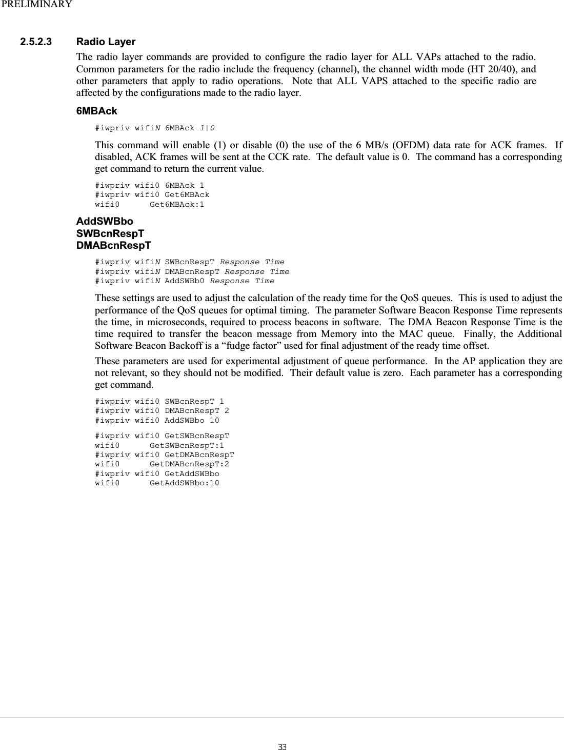
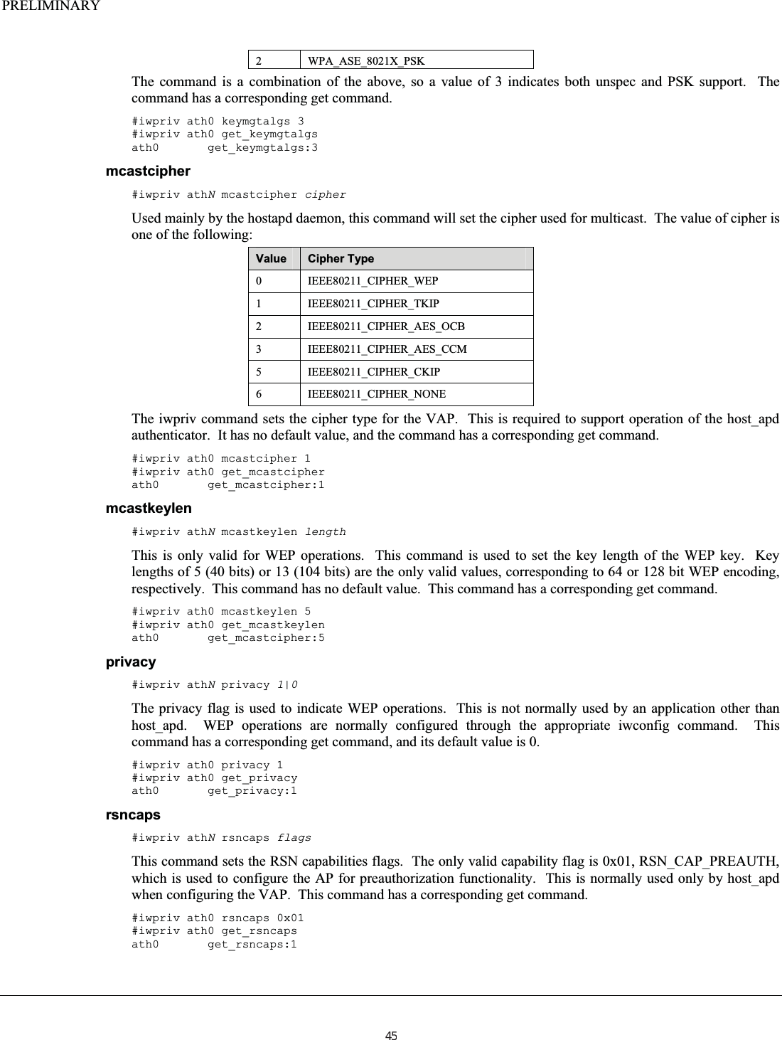
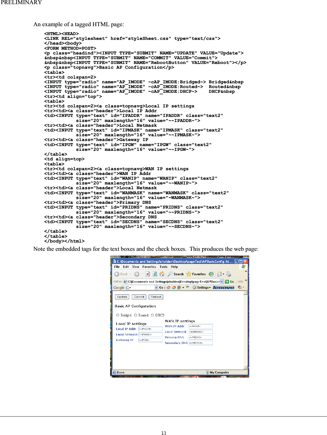
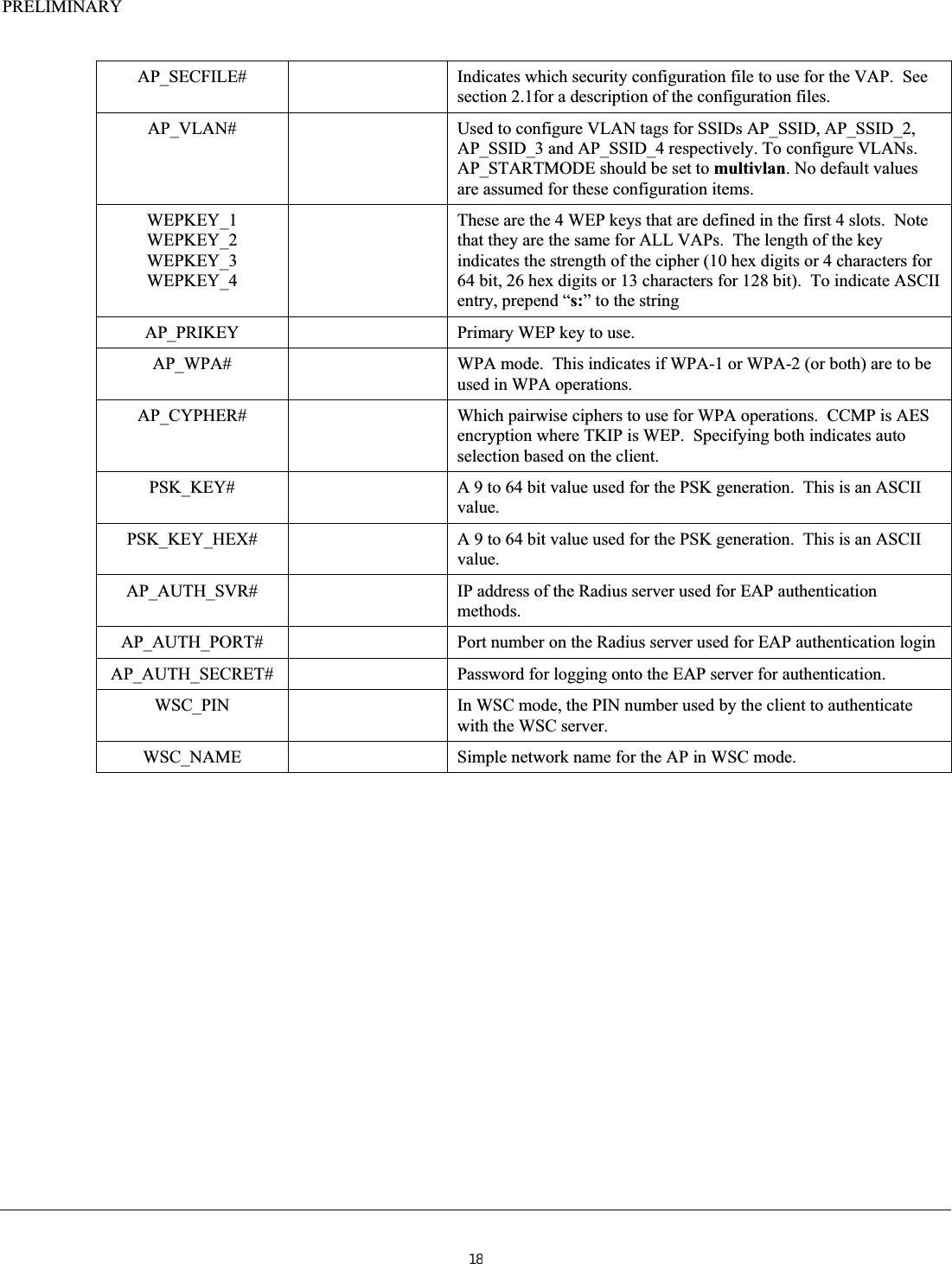
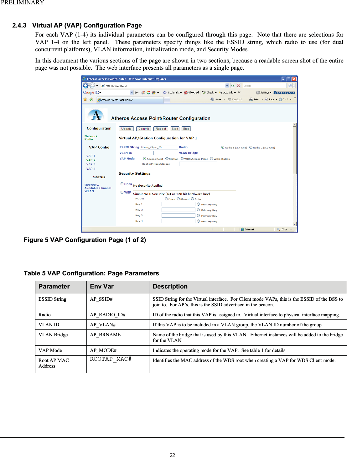
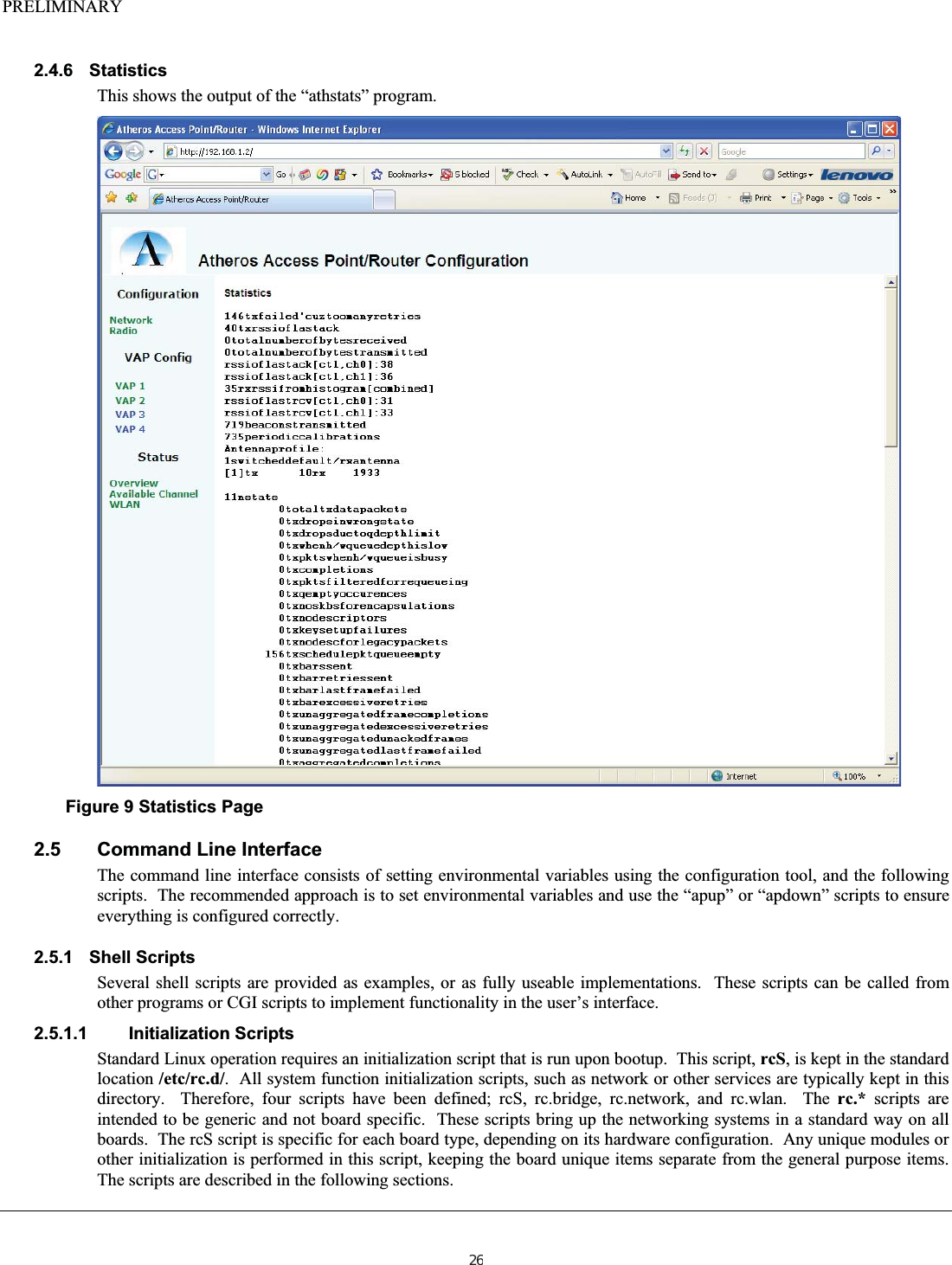
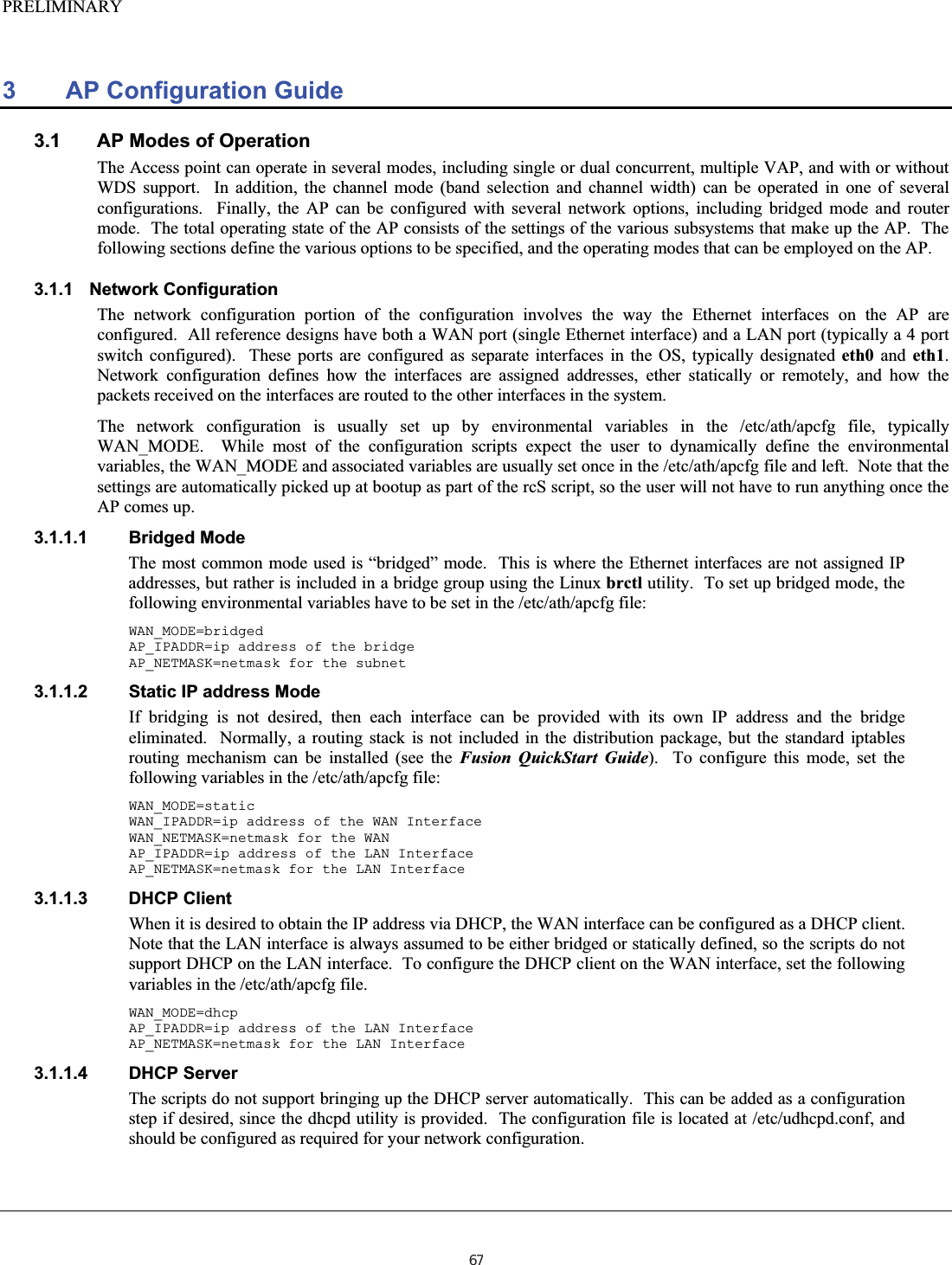
![PRELIMINARY setfilter#iwpriv athN setfilter filterThis command allows an application to specify which management frames it wants to receive from the VAP. This will cause the VAP to forward the indicated frames to the networking stack. The filter is a set of bits with the following values: Bit Frame type to forward 0x01 Beacon 0x02 Probe Request 0x04 Probe Response 0x08 Association Request 0x10 Association Response 0x20 Authentication 0x40 Deauthentication 0x80 Disassociation 0xff ALL This command is normally used by host_apd for configuring the VAP. It does NOT have a corresponding get command. #iwpriv ath0 setfilter 0x24 setiebuf getiebuf These commands are used by an application to set/get application Information Elements into/from various frame types. The ieee80211req_getset_appiebuf structure is passed as an argument to the ioctl. There is no command line equivalent for these commands, but the command does show up as a valid iwpriv command. The definition of the required data structure is as follows: struct ieee80211req_getset_appiebuf { u_int32_t app_frmtype; /*management frame type for which buffer is added*/ u_int32_t app_buflen; /*application supplied buffer length */ u_int8_t app_buf[]; };setkey delkey The host_apd application is required to do periodic rekeying of the various connections. These commands allow for management of the key cache. The setkey command receives the ieee80211req_key structure as an argument. This structure is defined as follows: struct ieee80211req_key { u_int8_t ik_type; /* key/cipher type */ u_int8_t ik_pad; u_int16_t ik_keyix; /* key index */ u_int8_t ik_keylen; /* key length in bytes */ u_int8_t ik_flags; u_int8_t ik_macaddr[IEEE80211_ADDR_LEN]; u_int64_t ik_keyrsc; /* key receive sequence counter */ u_int64_t ik_keytsc; /* key transmit sequence counter */ u_int8_t ik_keydata[IEEE80211_KEYBUF_SIZE+IEEE80211_MICBUF_SIZE];};The delkey command will pass the structure ieee80211req_del_key, as follows: struct ieee80211req_del_key { u_int8_t idk_keyix; /* key index */ u_int8_t idk_macaddr[IEEE80211_ADDR_LEN]; };Neither of these commands have any corresponding command line equivalents. 46](https://usermanual.wiki/Uniform/AG1311/User-Guide-2120934-Page-46.png)
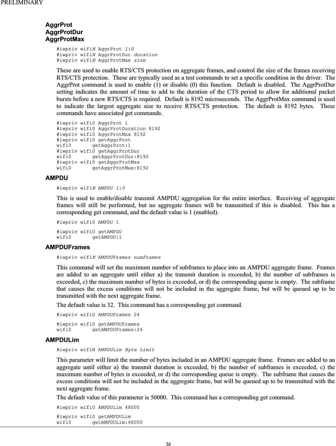
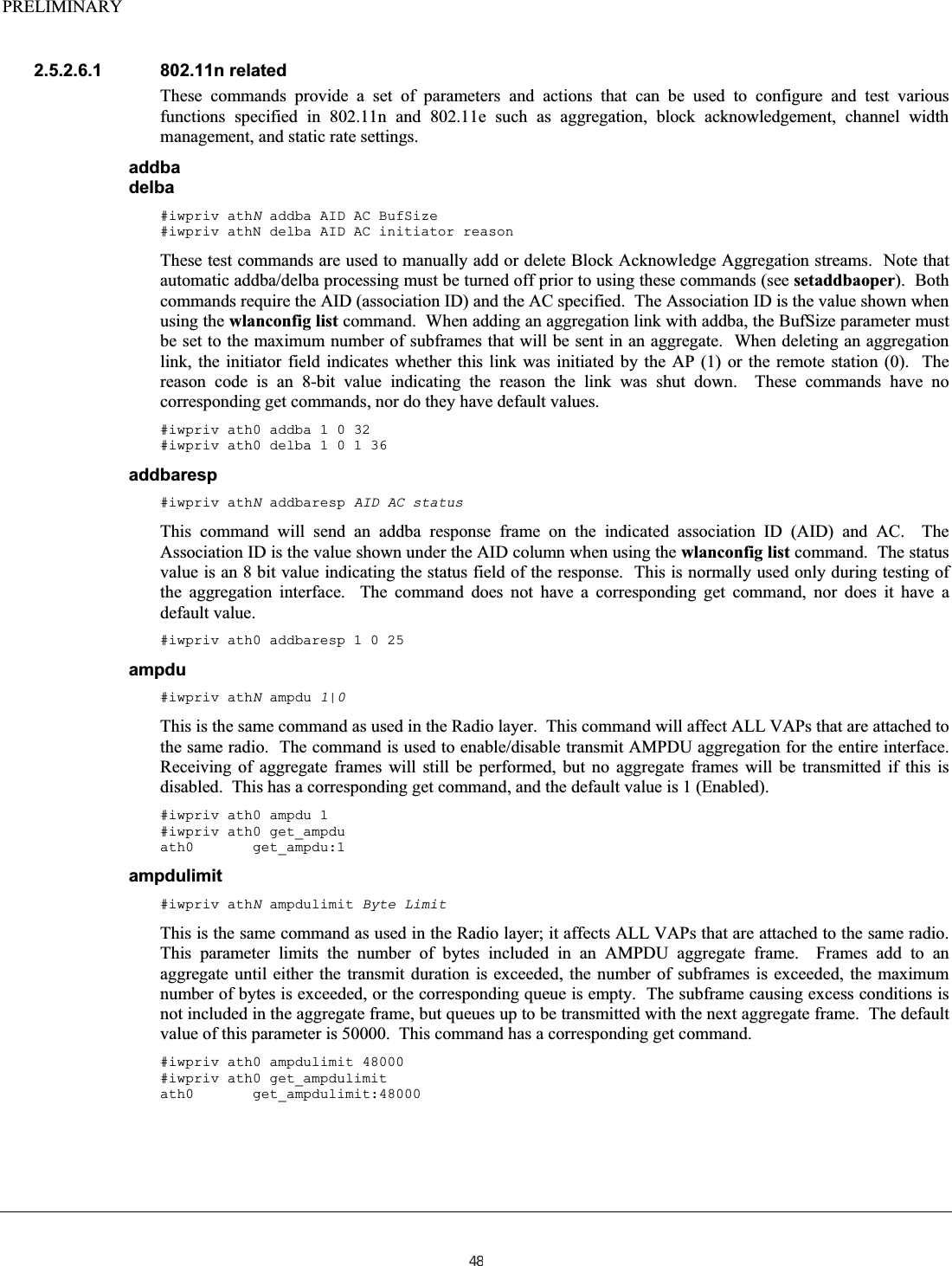
![PRELIMINARY setmlmeAnother of the host_apd support commands, this command is used to perform direct access to the MLME layer in the driver. This allows an application to start or terminate a specific association. Note that the MLME_ASSOC sub command only makes sense for a station (AP won’t start an association). This command will pass the ieee80211req_mlme structure: struct ieee80211req_mlme { u_int8_t im_op; /* operation to perform */#define IEEE80211_MLME_ASSOC 1/* associate station */#define IEEE80211_MLME_DISASSOC 2/* disassociate station */#define IEEE80211_MLME_DEAUTH 3/* deauthenticate station */#define IEEE80211_MLME_AUTHORIZE 4/* authorize station */#define IEEE80211_MLME_UNAUTHORIZE 5/* unauthorize station */ u_int16_t im_reason; /* 802.11 reason code */ u_int8_t im_macaddr[IEEE80211_ADDR_LEN]; };This command has no command line equivalent. ucastcipher #iwpriv athN ucastcipher This command is used mainly by the host_apd authenticator, and sets the unicast cipher type to the indicated value. See the mcastcipher command for the definition of the values. This command has a corresponding get command, but no default value. #iwpriv ath0 ucastcipher 2 #iwpriv ath0 get_uciphers ath0 get_uciphers:2 ucastkeylen #iwpriv athN ucastkeylen lengthThis is only valid for WEP operations. This command is used to set the key length of the WEP key for unicast frames. Key lengths of 5 (40 bits) or 13 (104 bits) are the only valid values, corresponding to 64 or 128 bit WEP encoding, respectively. This command has no default value. This command has a corresponding get command. #iwpriv ath0 ucastkeylen 5 #iwpriv ath0 get_ucastkeylen ath0 get_ucastcipher:5 wpa #iwpriv athN wpa WPA ModeThis command will set the desired WPA modes. The value of WPA Mode indicates the level of support; 0 = No WPA support 1 = WPA Support 2 = WPA2 Support 3 = Both WPA and WPA2 support. This command is typically overridden by the setting in the hostapd configuration file, which uses the same interface to set the WPA mode, so this command is nor normally used during configuration. This command has a corresponding get command. The default value is 0. #iwpriv ath0 wpa 3 #iwpriv ath0 get_wpa ath0 get_wpa:0 47](https://usermanual.wiki/Uniform/AG1311/User-Guide-2120934-Page-47.png)
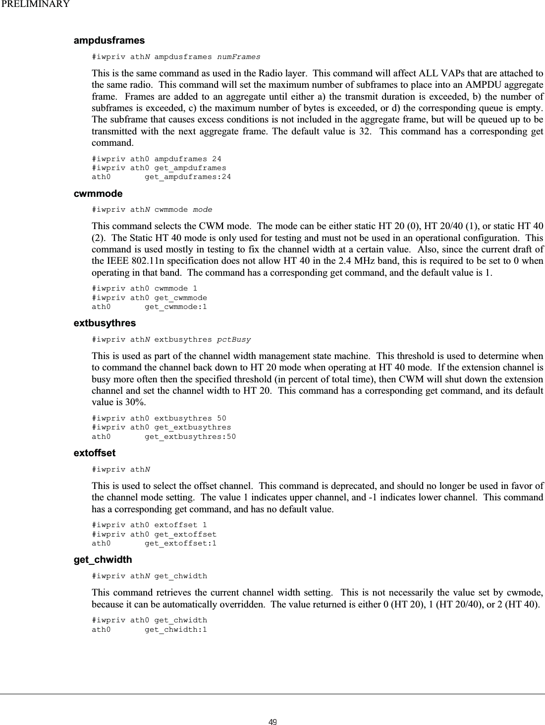
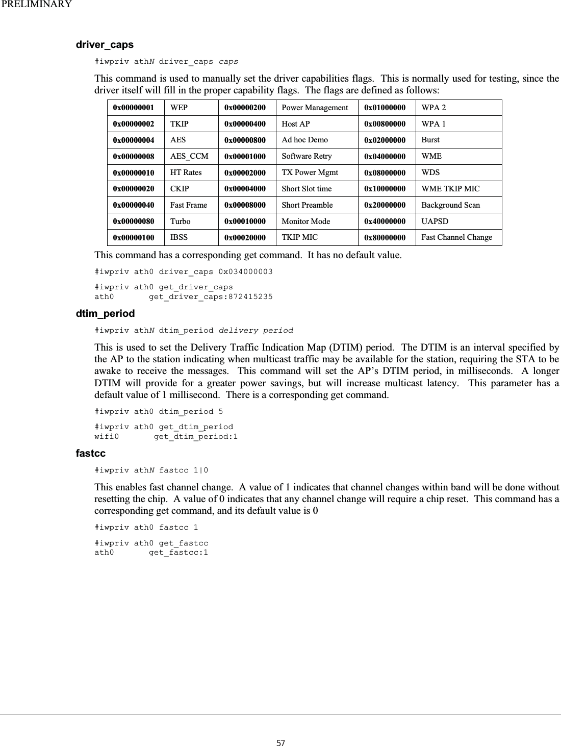
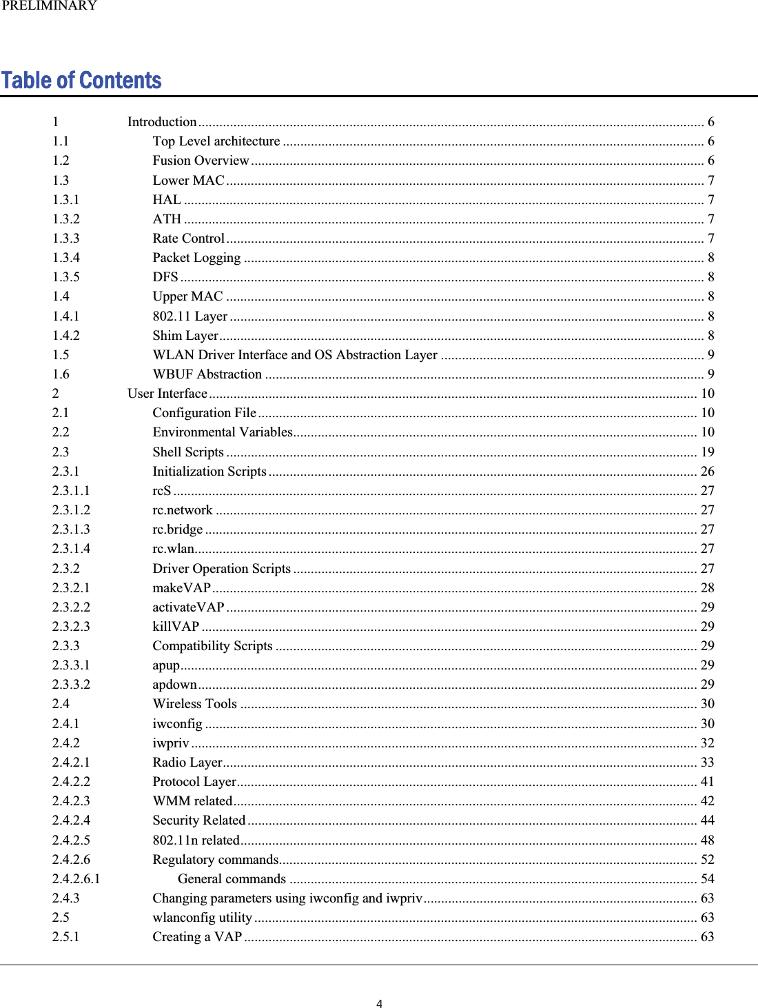
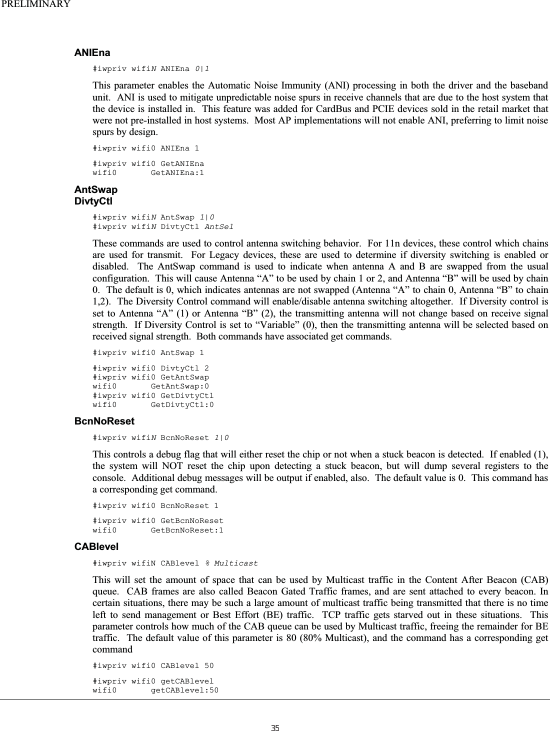
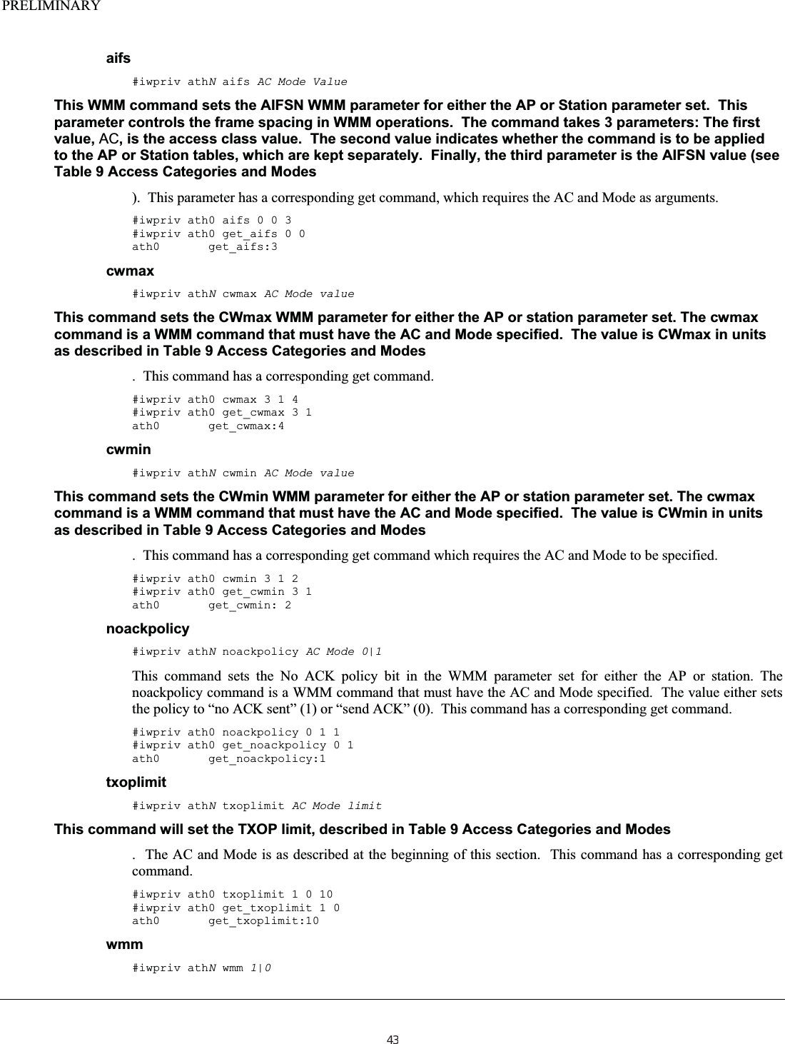
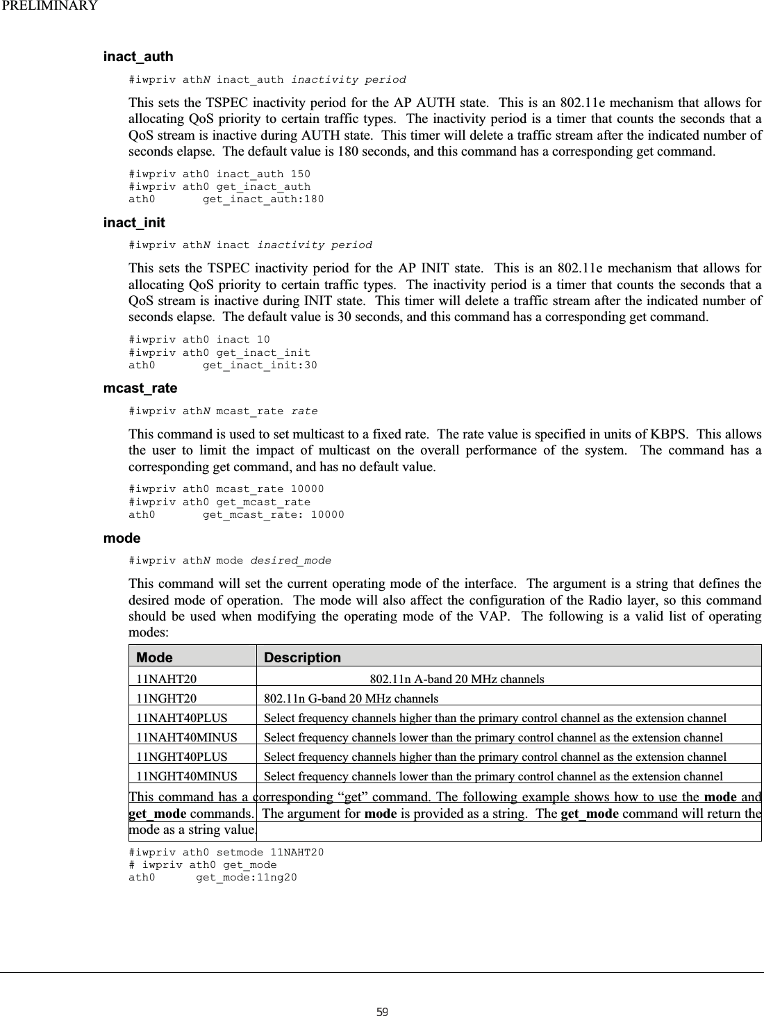
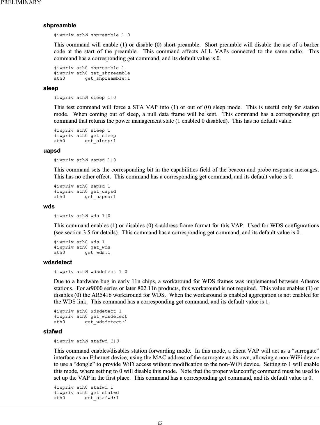
![PRELIMINARYgetchaninfo This command is used by external applications to get channel information from the driver. An example application is the wlanconfig tool that uses this interface to get the channel information. The wireless tools do not know how to parse the information provided, since it is returned in an Atheros driver specific data structure. The data structures used are defined as follows: struct ieee80211req_chaninfo { u_int ic_nchans; struct ieee80211_channel ic_chans[IEEE80211_CHAN_MAX]; };struct ieee80211_channel { u_int16_t ic_freq; /* setting in MHz */ u_int32_t ic_flags; /* see below */ u_int8_t ic_flagext; /* see below */ u_int8_t ic_ieee; /* IEEE channel number */ int8_t ic_maxregpower; /* maximum regulatory Tx power in dBm */ int8_t ic_maxpower; /* maximum Tx power in dBm */ int8_t ic_minpower; /* minimum Tx power in dBm */};There is not command line equivalent interface for this command. getRadio#iwpriv athN getRadio For dual concurrent operations, it is desirable to be able to determine which radio a particular VAP is attached to. This command will return the index of the associated radio object (wifiN, where N is the radio number). #iwpriv ath0 getRadio ath0 getRadio:0 hide_ssid#iwpriv athN hide_ssid 0|1This will “hide” the SSID, disabling it in the transmitted beacon, when enabled. This is used for secure situations where the AP does not want to advertise the SSID name. A value of 0 will enable the SSID in the transmitted beacon. This command has a corresponding get command, and its default value is 0. #iwpriv ath0 hide_ssid 1 #iwpriv ath0 get_hide_ssid ath0 get_hide_ssid:1 inact#iwpriv athN inact inactivity periodThis sets the TSPEC inactivity period for the AP RUN state. This is an 802.11e mechanism that allows for allocating QoS priority to certain traffic types. The inactivity period is a timer that counts the seconds that a QoS stream is inactive during RUN state. This timer will delete a traffic stream after the indicated number of seconds elapse. The default value is 300 seconds, and this command has a corresponding get command. #iwpriv ath0 inact 250 #iwpriv ath0 get_inact ath0 get_inact:300 58](https://usermanual.wiki/Uniform/AG1311/User-Guide-2120934-Page-58.png)
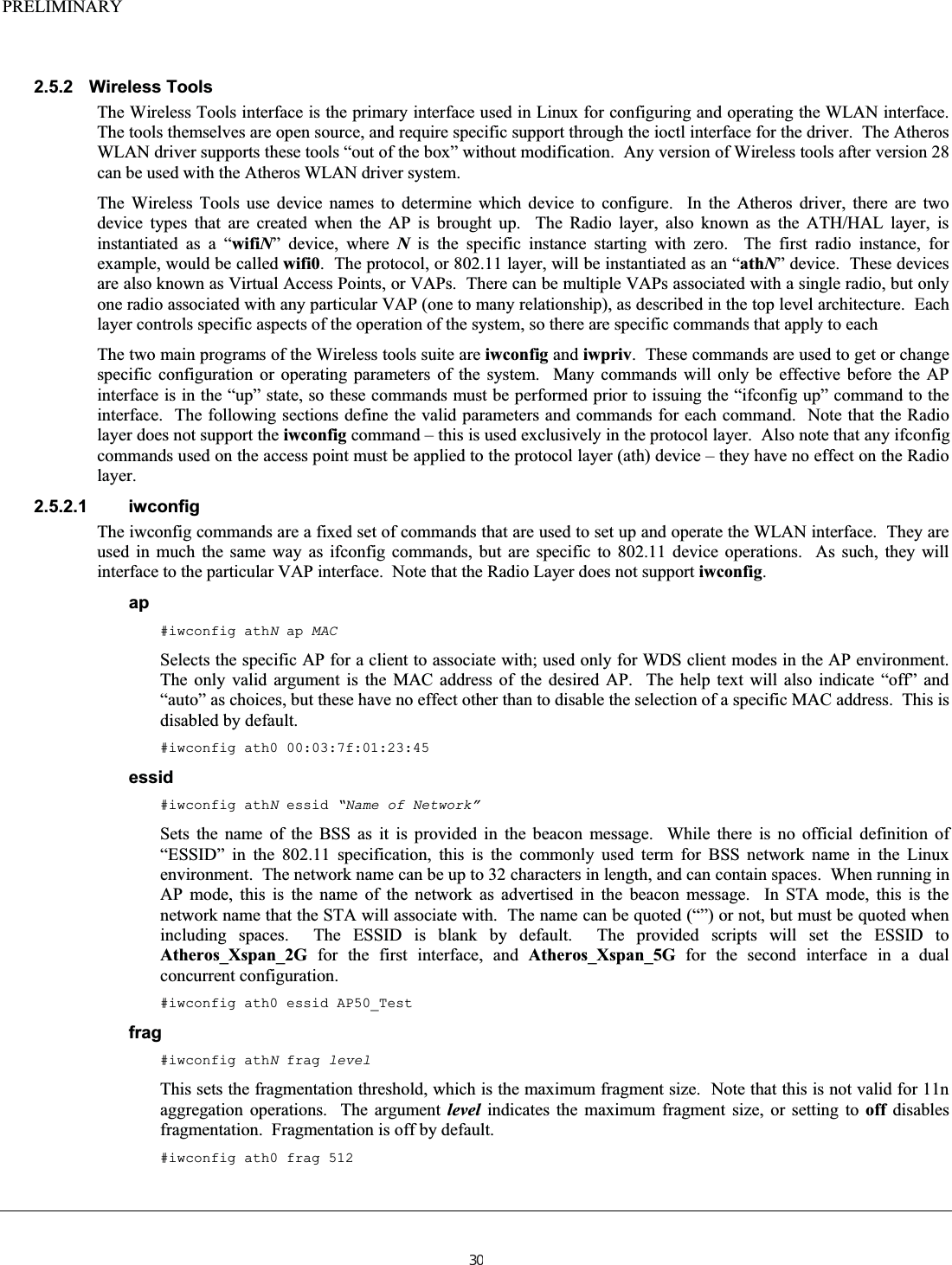
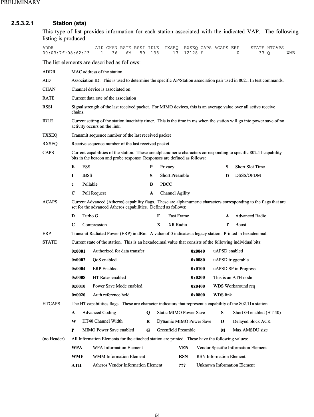
![PRELIMINARY 2.5.2.7 Changing parameters using iwconfig and iwpriv Many of the parameters that can be accessed via iwconfig and iwpriv are initialization parameters. If they are changed while the AP is running, they may not take effect until the VAP is brought down and up. For multiple BSS (multiple VAP) configurations, some iwpriv parameters may affect ALL VAPs, not just the one of interest. Normally, the best practice is to bring down ALL VAPs prior to making configuration changes using the “ifconfig down” command on the interface, and then bringing them back up using the “ifconfig up” command. It has been attempted to indicate those commands that may have adverse effects in the documentation for the command, however not all effects may have been documented. Please keep in mind the nature of multiple VAP configurations that use multiple radios, and use caution when changing parameters on the fly. 2.5.3 wlanconfig utility The wlanconfig utility is an Atheros utility used to manage VAP instances. It provides the primary method to instantiate a VAP, list the VAP status, and delete the VAP instance. It is an integral part of the configuration scripts. The Create, List, and Delete interfaces are described in the following sections. 2.5.3.1 Creating a VAP Creating a VAP requires a few parameters to indicate the specific nature of the VAP. A VAP can be either a client node or an infrastructure node. Infrastructure notes are called “master” nodes, and client nodes are called “managed” nodes. The following command is used to create a VAP instance: # wlanconfig ath[N] create wlandev wifiN wlanmode [ap|sta|mon] [bssid] [nosbeacon] The arguments are defined as follows: Argument Description ath[N] Name of the VAP. If the number at the end of the name is omitted, the system will automatically use the next available interface number. The VAP name “ath” is not required, any text string will do. create Verb indicating create action wlandev wifiNIndicates which interface to attach the VAP to. The interface number is required for this argument. For dual concurrent operations, N indicates which radio to attach the VAP to. wlanmode mode Indicates the mode to open the VAP into. The valid modes are “ap”, indicating an infrastructure node, “sta” indicating a station (client) node, and “mon” indicating a monitor VAP. Note that “mon” is not implemented in the configuration scripts. bssid Optional parameter indicating that the MAC address should be cloned from the first VAP for this interface. Not normally specified. nosbeacon Indicates that no beacons will be transmitted from this VAP. Used as part of station (client) mode. 2.5.3.2 Listing VAP Parameters The list command provides an extended listing of parameters from the VAP. Depending on the type of list for each associated station. The list command is followed by a print of the VAP association list with the associated parameters: # wlanconfig athN list [sta|ap|chan|keys|caps|wme] The argument to the list verb defines the type of listing to produce. Each type is described in the following sections. 63](https://usermanual.wiki/Uniform/AG1311/User-Guide-2120934-Page-63.png)
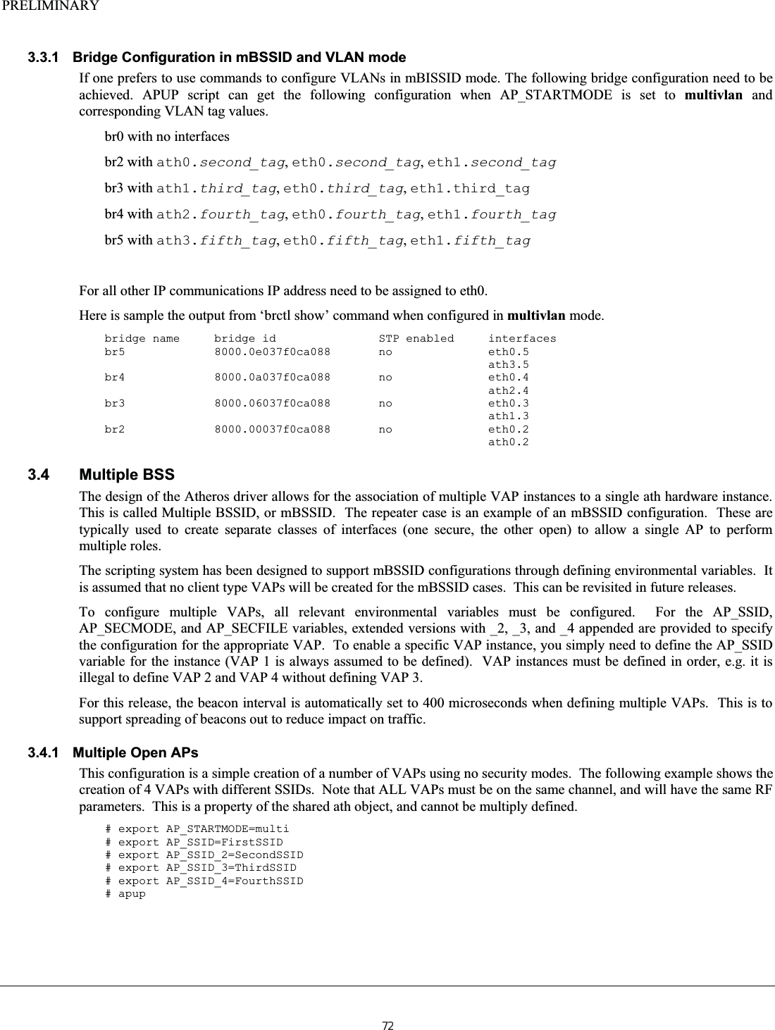
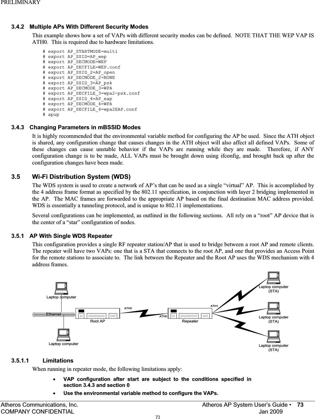
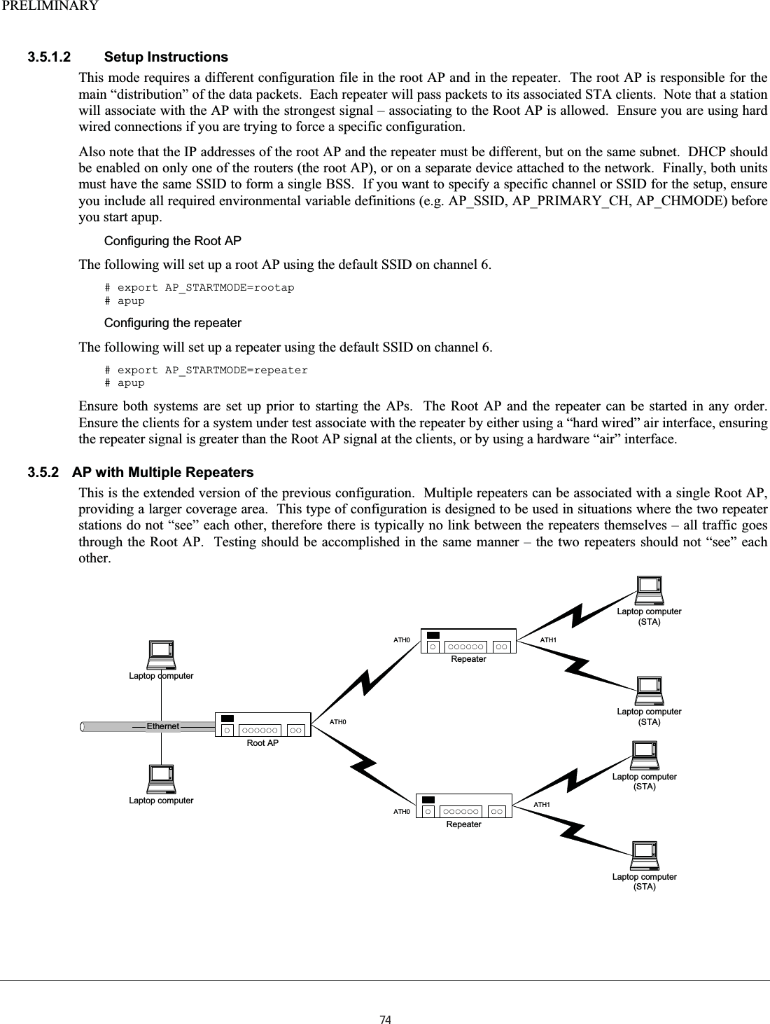
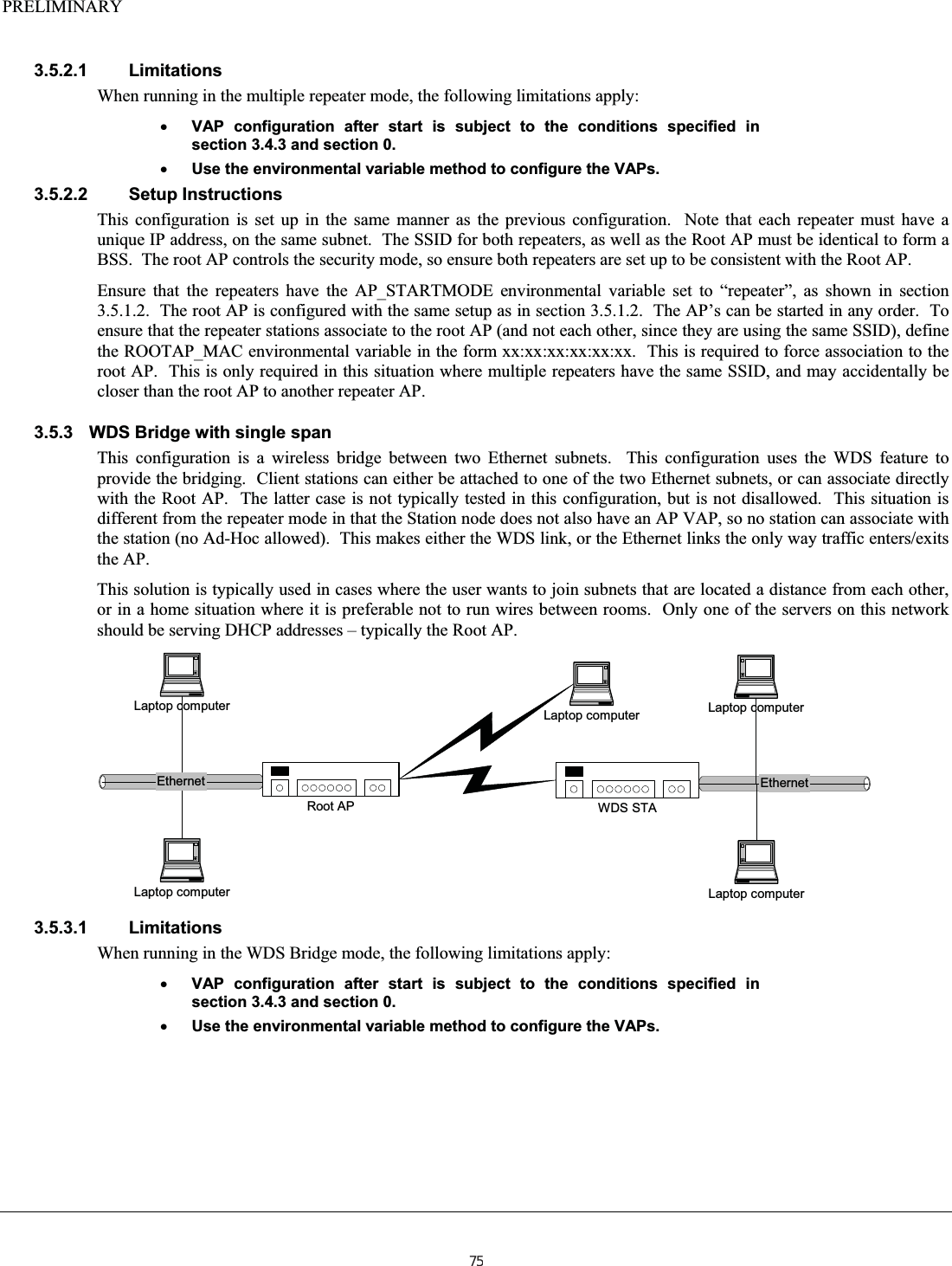
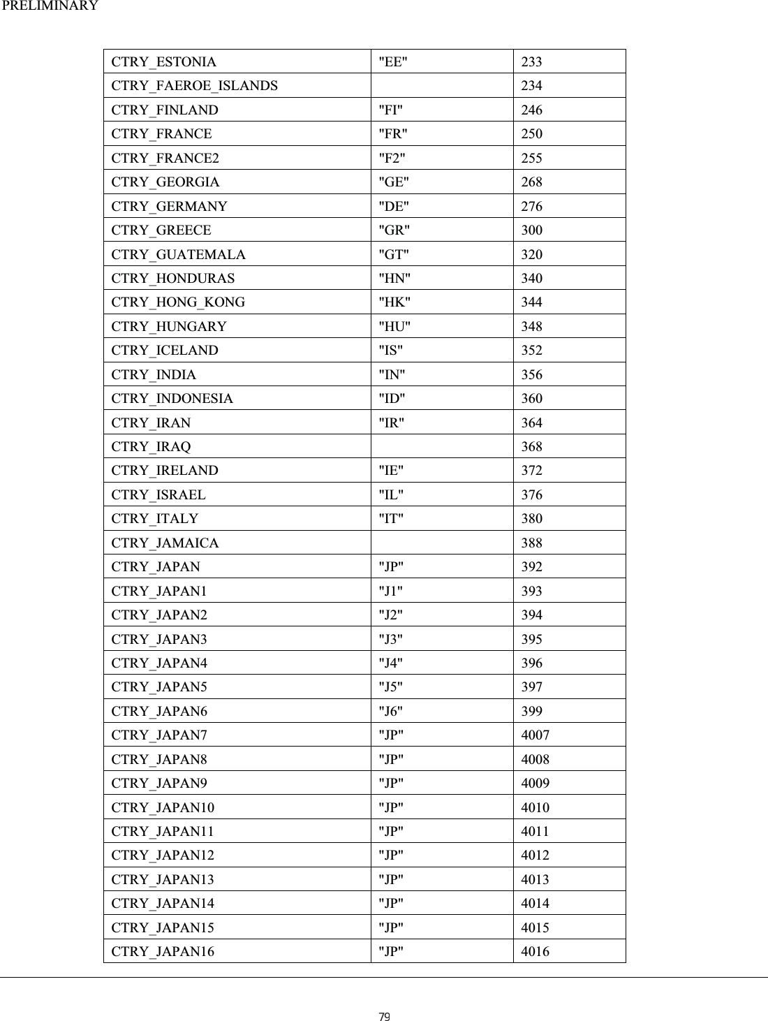
![PRELIMINARY 3.3 VLAN Configuration The Linux utility “vconfig” is provided to enable IEEE 802.1QVLAN support. A VLAN is a “virtual” network that coexists over an actual physical interface, but only stations that are configured to interface to the VLAN participate in network traffic on the VLAN. Normally VLANs have a DHCP server that provides an IP address for the VLAN interface. Typically, some sort of security is required to start participation on a VLAN, but this is the responsibility of higher layers (such as the DHCP server). The APUP script is can configure the AP with VLANS in mBSSID mode. To configure VLANS, AP_STARTMODE need to be set to multivlan and variables AP_VLAN, AP_VLAN_2, AP_VLAN_3 and AP_VLAN_4 need to be set to corresponding VLAN tag values. For security support AP_SECMODE and AP_SECFILE variables need to be set and corresponding security feature will be activated on tagged interface. # export AP_STARTMODE=multivlan # export AP_SSID=FirstSSID # export AP_VLAN=2 # export AP_SSID_2=SecondSSID # export AP_VLAN=3 # export AP_SSID_3=ThirdSSID # export AP_SECMODE_3=WPA # export AP_SECFILE_3=wpa2-psk.conf # export AP_SSID_4=FourthSSID # export AP_VLAN_4=10 # export AP_SECMODE_4=WPA # export AP_SECFILE_4=wpa2EAP.conf # apup After “apup” necessary bridges with names br2 , br3, br4 and br5 will be configured with corresponding tagged athx.tag ,eth0.tag and eth1.tag interfaces. The remainder of this section explains Linux commands to configure singe VLAN interface on AP. The vconfig command is quite straightforward. The following commands are used (taken from the Linux MAN pages). Note the added # to indicate the command prompt: To Add an interface to a VLAN #vconfig add [interface-name] [vlan-id]creates a vlan-device on [interface-name] (typically ath0 or ath1 in our scenarios). The resulting vlan-device will be called according to the naming convention set. To remove a VLANinterface #vconfig rem [vlan-device] Removes the named vlan-device To configure the VLANinterface #vconfig set_flag [vlan-device] 0 | 1When 1, Ethernet header reorders are turned on. Dumping the device will appear as a common Ethernet device without VLANs. When 0(default) however, Ethernet headers are not reordered, which results in vlan tagged packets when dumping the device. Usually the default gives no problems, but some packet filtering programs might have problems with it #vconfig set_egress_map [vlan-device] [skb-priority] [vlan-qos] This flags that outbound packets with a particular skb-priority should be tagged with the particular vlan priority vlan-qos. The default vlan priority is 0. #vconfig set_ingress_map [vlan-device] [skb-priority] [vlan-qos] This flags that inbound packets with the particular vlan priority vlan-qos should be queued with a particular skb-priority. The default skb-priority is 0. #vconfig set_name_type VLAN_PLUS_VID | VLAN_PLUS_VID_NO_PAD | DEV_PLUS_VID | DEV_PLUS_VID_NO_PAD Sets the way vlan-device names are created. Use vconfig without arguments to see the different formats. Additional description of VLAN configuration can be found at the URL: http://www.linuxjournal.com/article/726871](https://usermanual.wiki/Uniform/AG1311/User-Guide-2120934-Page-71.png)