Uniform AG1311 Contactless Smart Card Reader Module User Manual
Uniform Industrial Corp. Contactless Smart Card Reader Module Users Manual
Uniform >
Users Manual
őųŦűŢųŦť ŌŦůůźġńũŦů
ŇŇŏĵıijłġʼnŢųťŸŢųŦġŔűŦŤį łűűųŰŷŦť ŔűŦůŤŦųġńũŦů ĴįIJIJįijıIJĴ
œŦŷŪŴŪŰů ŷŦųġIJįIJ
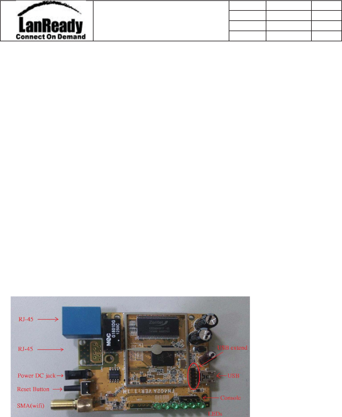
Description
ĹıijįIJIJůġŸŪŧŪġŔźŴŵŦŮġŎŰťŶŭŦ
System
CPU łŵũŦųŰŴġłœĺĴĴIJġĩłœIJĴIJIJĪ
Flash ĹġŎŃ
DRAM ĴijġŎŃ
RTC ŏŰ
Ethernet IJıİIJııġŎţűŴġŇŢŴŵġņŵũŦųůŦŵġīijġĩŰűŵŪŰůŢŭġŵŰġŐůŦġœŋĮĵĶĪ
RF IJŕIJœĭġĹıijįIJIJůĭġũŪĮűŰŸŦųġĩĶııġŮŸĪ(2.4GHz Band)
Switch port
Power Input
DC jack ĶŗĭġŮŪůŪŅńġŋŢŤŬ
I/O & Peripherial
JTAG ŏİł
RS-232 (console) ŤŰůŴŰŭŦġűŰųŵġŸŪŵũġĵĮűŪůġűŪůġũŦŢťġŤŰůůŦŤŵŰų
USB ŐůŦġűŰųŵĭġŖŔŃġijįıġũŰŴŵ
USB extension ķĮűŪůġŦŹŵŦůťŦťġŧųŰŮġŖŔŃġűŰųŵ
Wifi antenna ŷŪŢġŔŎłġœŇġŤŰůůŦŤŵŰųġŧŰųġŦŹŵŦųůŢŭġŢůŵŦůůŢ
LEDs ķġōņŅŴ
Reset Button ŚŦŴĭġŔŰŧŵŸŢųŦġœŦŴŦŵ
Environmental
PCB dimension ĶĸŮŮġīġĸıġŮŮ
Housing ŕŅŃ
Operating temperature
ıƱńġſĶıƱń
Humidity ĺıĦġůŰůĮŤŰůťŦůŴŪŷŦ
1
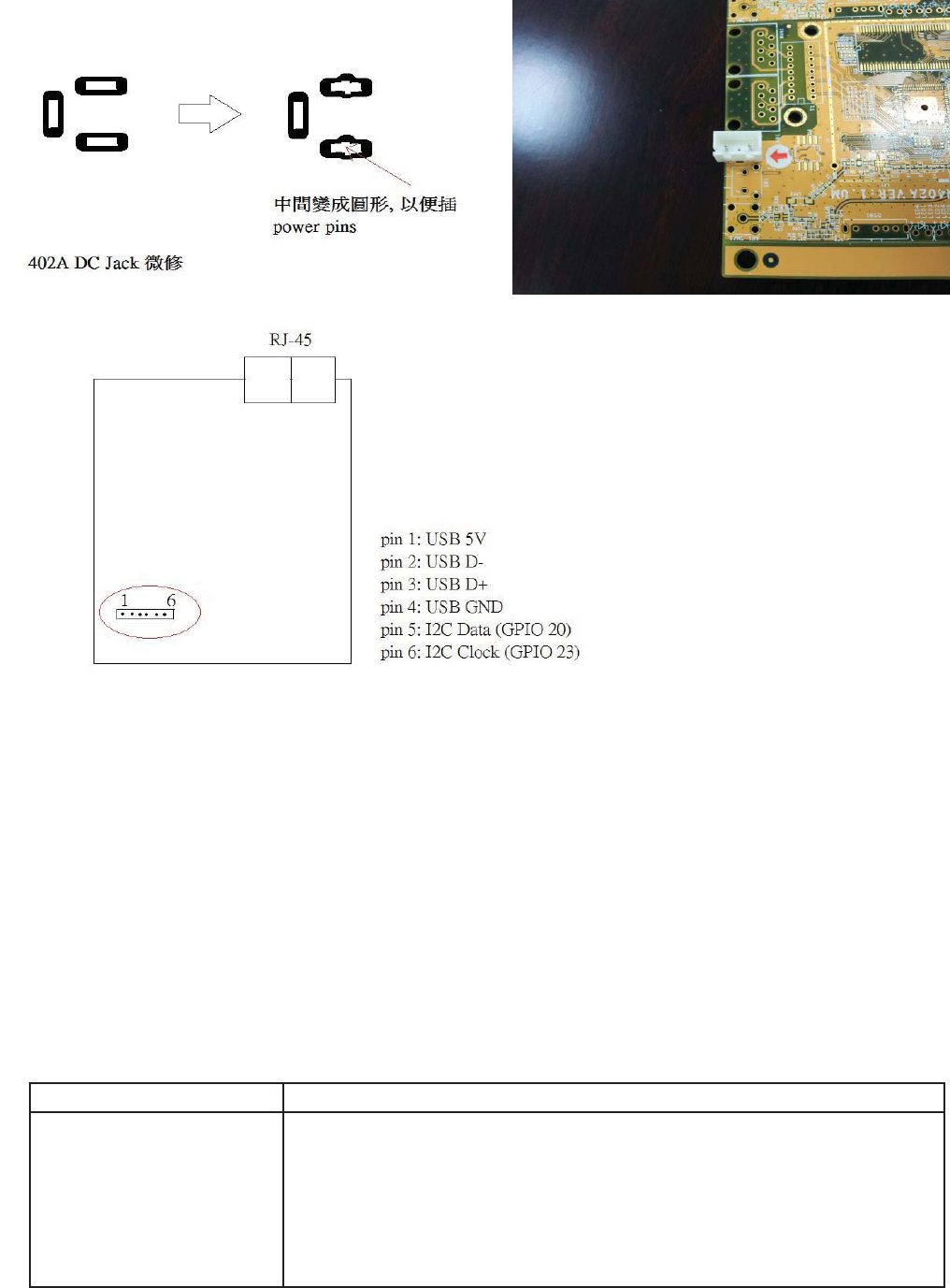
GPIO definition
ňőŊŐġı ōņŅġIJ
ňőŊŐġIJĴ ōņŅġij
ňőŊŐġIJĸ ōņŅġĴ
őŰŸŦų ōņŅġĵ
ňőŊŐġijĸ ōņŅġĶ
ňőŊŐġijķ ōņŅġķ
ňőŊŐġijı ŊƳńġŅŢŵŢ
ňőŊŐġijĴ ŊƳńġńŭŰŤŬ
ňőŊŐġIJij œŦŴŦŵġţŶŵŵŰůġĩŴŰŧŵŸŢųŦġœŦŴŦŵĪ
Revision record
ųŦŷįIJįIJŎ
2

PRELIMINARY
Revision History
Revision Date Description
0.5 November
2008
Original Release
0.6 November
2008
Updated to include Web interface and configuration methods.
0.7 Jan 2010 Updated for UMAC baseline
3

PRELIMINARY
Table of Contents
1 Introduction................................................................................................................................................ 6
1.1 Top Level architecture ........................................................................................................................ 6
1.2 Fusion Overview................................................................................................................................. 6
1.3 Lower MAC........................................................................................................................................ 7
1.3.1 HAL .................................................................................................................................................... 7
1.3.2 ATH .................................................................................................................................................... 7
1.3.3 Rate Control........................................................................................................................................ 7
1.3.4 Packet Logging ................................................................................................................................... 8
1.3.5 DFS ..................................................................................................................................................... 8
1.4 Upper MAC ........................................................................................................................................ 8
1.4.1 802.11 Layer ....................................................................................................................................... 8
1.4.2 Shim Layer.......................................................................................................................................... 8
1.5 WLAN Driver Interface and OS Abstraction Layer ........................................................................... 9
1.6 WBUF Abstraction ............................................................................................................................. 9
2 User Interface........................................................................................................................................... 10
2.1 Configuration File............................................................................................................................. 10
2.2 Environmental Variables................................................................................................................... 10
2.3 Shell Scripts ...................................................................................................................................... 19
2.3.1 Initialization Scripts .......................................................................................................................... 26
2.3.1.1 rcS ..................................................................................................................................................... 27
2.3.1.2 rc.network ......................................................................................................................................... 27
2.3.1.3 rc.bridge ............................................................................................................................................ 27
2.3.1.4 rc.wlan............................................................................................................................................... 27
2.3.2 Driver Operation Scripts ................................................................................................................... 27
2.3.2.1 makeVAP.......................................................................................................................................... 28
2.3.2.2 activateVAP ...................................................................................................................................... 29
2.3.2.3 killVAP ............................................................................................................................................. 29
2.3.3 Compatibility Scripts ........................................................................................................................ 29
2.3.3.1 apup................................................................................................................................................... 29
2.3.3.2 apdown.............................................................................................................................................. 29
2.4 Wireless Tools .................................................................................................................................. 30
2.4.1 iwconfig ............................................................................................................................................ 30
2.4.2 iwpriv ................................................................................................................................................ 32
2.4.2.1 Radio Layer....................................................................................................................................... 33
2.4.2.2 Protocol Layer................................................................................................................................... 41
2.4.2.3 WMM related.................................................................................................................................... 42
2.4.2.4 Security Related ................................................................................................................................ 44
2.4.2.5 802.11n related.................................................................................................................................. 48
2.4.2.6 Regulatory commands....................................................................................................................... 52
2.4.2.6.1 General commands .................................................................................................................... 54
2.4.3 Changing parameters using iwconfig and iwpriv..............................................................................63
2.5 wlanconfig utility .............................................................................................................................. 63
2.5.1 Creating a VAP ................................................................................................................................. 63
4

PRELIMINARY
2.5.2 Listing VAP Parameters.................................................................................................................... 63
2.5.2.1 Station (sta) ....................................................................................................................................... 64
2.5.2.2 AP List (ap)....................................................................................................................................... 65
2.5.2.3 Channel (chan).................................................................................................................................. 65
2.5.2.4 Capabilities (caps)............................................................................................................................. 66
2.5.2.5 WMM Configuration (wme) ............................................................................................................. 66
2.5.3 Deleting a VAP ................................................................................................................................. 66
3 AP Configuration Guide .......................................................................................................................... 67
3.1 AP Modes of Operation .................................................................................................................... 67
3.1.1 Network Configuration ..................................................................................................................... 67
3.1.1.1 Bridged Mode ................................................................................................................................... 67
3.1.1.2 Static IP address Mode...................................................................................................................... 67
3.1.1.3 DHCP Client ..................................................................................................................................... 67
3.1.1.4 DHCP Server .................................................................................................................................... 67
3.1.2 Radio Configuration.......................................................................................................................... 68
3.1.3 Operating Mode ................................................................................................................................ 68
3.2 Security ............................................................................................................................................. 69
3.2.1 WEP Configuration........................................................................................................................... 69
3.2.2 WPA.................................................................................................................................................. 69
3.2.2.1 Enabling WPA Preauthorization (AP only) ...................................................................................... 69
3.2.2.2 WPA PSK ......................................................................................................................................... 70
3.2.2.3 WPA Enterprise ................................................................................................................................ 70
3.2.3 WSC Configuration........................................................................................................................... 70
3.2.3.1 Including WSC in the build............................................................................................................... 70
3.2.3.2 Activating WSC support on the AP .................................................................................................. 70
3.3 VLAN Configuration ........................................................................................................................ 71
3.3.1 Bridge configuration in mBSSID and VLAN mode ......................................................................... 72
3.4 Multiple BSS..................................................................................................................................... 72
3.4.1 Multiple Open APs............................................................................................................................ 72
3.4.2 Multiple AP’s with different security modes .................................................................................... 73
3.4.3 Changing Parameters in mBSSID Modes ......................................................................................... 73
3.5 Wi-Fi Distribution System (WDS).................................................................................................... 73
3.5.1 AP With Single WDS Repeater ........................................................................................................ 73
3.5.1.1 Limitations ........................................................................................................................................ 73
3.5.1.2 Setup Instructions.............................................................................................................................. 74
3.5.2 AP with Multiple Repeaters.............................................................................................................. 74
3.5.2.1 Limitations ........................................................................................................................................ 75
3.5.2.2 Setup Instructions.............................................................................................................................. 75
3.5.3 WDS Bridge with single span........................................................................................................... 75
3.5.3.1 Limitations ........................................................................................................................................ 75
3.5.3.2 Setup Instructions.............................................................................................................................. 76
3.5.4 WDS Bridge with multiple span ....................................................................................................... 76
3.5.4.1 Limitations ........................................................................................................................................ 76
3.5.4.2 Setup Instructions.............................................................................................................................. 77
3.6 Dual Concurrent Operations ............................................................................................................. 77
Appendix A Country Code Definition.......................................................................................................................... 78
5

PRELIMINARY
1 Introduction
This manual provides information on the design and use of the Atheros AP system. This system consists of the OS kernel,
utility functions, and the Atheros AP Driver.
1.1 Top Level architecture
This driver is based on the Atheros Universal Driver Architecture. This architecture abstracts the WLAN driver into
various common sections that can be used for a variety of operating systems. OS specific components are well isolated,
and the Atheros Driver Framework (ADF) provides abstractions of OS services such that the common code does not
have to have ANY OS specific coding. The data packet abstraction, called WBUF, allows the driver to handle different
OS specific frame formats in a common way. This abstraction has been used with both SKB and MBUF frame
architectures successfully, and also works with Windows frame architectures.
The software design is moved to a further modularized architecture that allows for better isolation of data items and
object oriented design. . Global variables are eliminated, and all layer functions are contained within a call structure.
1.2 Fusion Overview
The main driver for the Fusion architecture was the use of a common code base to support multiple operating systems.
This allows for more efficient development processes, as well as the synergy of getting bug fixes for all major platforms
at the same time.
The Fusion architecture consists of 4 major components. The first is the WLAN driver interface, which is the operating
system unique interface adaptor that translates OS specific calls to Fusion “generic” calls. The second is the Upper
MAC layer, which contains the bulk of the 802.11 protocol processing for both station and AP applications. In earlier
versions of Fusion, this layer was implemented specifically for each operating system. In later versions, a common
version of the Upper MAC is used to provide the protocol processing layer.
The third component is the Lower MAC, which contains the ATH and HAL layers. This layer is much more hardware
centric, and is designed to support the needs of the Atheros chipset architecture. The fourth component is the OS
Abstraction layer. This is a set of macros that is used to redefine “generic’ OS primitives into specific system calls that
perform the required function. Functions such as register read/write, translation of OS packets into WBUF abstractions,
and tasking control are all included in this section. A block diagram of the components and their relationship are shown
in Figure 1.
6
˪˴̅́˼́˺ʳ
15.21 "Changes or modifications are not expressly approved by the manufacturer could void the user's authority to operate
the equipment."
The following sentence has to be displayed on the outside of device in which the transmitter module is installed "Contains
FCC ID: TFJAG1311 "
This device uses, generates and radiated radio frequency energy. The radio frequency energy produced by this device is
well below the maximum exposure allows by Federal Communications Commission(FCC).

PRELIMINARY
Figure 1 Fusion Top Level Block Diagram
1.3 Lower MAC
The Lower MAC portion consists of two main components: The Hardware Abstraction Layer (HAL), and the
Atheros Device Object (ATH). The HAL contains all chip-specific settings and procedures that are performed
to initialize and operate the device. The ATH layer is responsible for managing the data flow into the input
queues of the hardware, as well as managing lower layer protocols, such as Block ACK processing.
1.3.1 HAL
HAL provides low-level primitives to program Atheros chipsets. HAL abstraction will allow runtime support of
multiple chipset families and defines a common body of functions between chipsets with chipset differences
being handled in specific components. Only low-level driver components can interface directly with HAL.
1.3.2 ATH
ATH_DEV module implements the low level MAC functionalities including:
x Unified transmit and receive path for both legacy and 11n chipsets.
x Advanced 11n MAC features: aggregation, RIFS, MIMO power save, etc.
x 802.11 network power save and device power state (D0-D3) management.
x Beacon generation and TSF management.
x Wake-On-Wireless support.
x Key cache management.
x RfKill, Customized LED and GPIO algorithms
ATH_DEV can be accessed through Atheros device object interface (section 1.2) by protocol shim layer.
1.3.3 Rate Control
The rate control algorithm attempts to transmit unicast packets at the optimum data rate. If there are changes in
the propagation channel, the rate control algorithm will automatically step up or down to a data rate that allows
reliable transmission at the fastest possible rate. The rate control can only be accessed by ath_dev, and should
not by protocol stacks.
OS Abstraction Layer
Atheros Device Object (ath dev)
Packet Logging
ATH DEV Rate Control DFS
Hardware Abstraction Layer
IEEE 802.11 Protocol Stack
AR5416
WLAN Driver Interface
LMAC Interface
Base Objects (channel, ic, node, VAP)
MLME PM
STA/AP SME Scanning/Roaming
Mgmt Frm
Config
AR5212
7

PRELIMINARY
1.3.4 Packet Logging
Packet logging provides a low level mechanism to capture driver activities. It can log activities like transmit,
receive, rate find and update, aggregation, ANI, and etc. Different operating system shall have its own tool to
enable packet log and retrieve the log buffer.
1.3.5 DFS
This module implements the DFS or Dynamic Frequency Selection algorithm, which enables wireless devices
operating in the 5GHz band to detect the presence of radar systems. If a radar system is detected, the wireless
device must avoid interfering with it and must automatically switch to another frequency.
1.4 Upper MAC
The Upper MAC is the portion of the MAC that performs most of the 802.11 protocol processing, and
provides the interface to the OS networking stack. In the Fusion implementation, the Upper MAC consists of
the 802.11 layer, and the so-called “shim” layer.
1.4.1 802.11 Layer
Most wireless LAN device driver today consists of two major components: a protocol stack and a low-level
driver. Usually the protocol stack contains IEEE802.11 state machine, scanning/roaming, IE processing, and
other device independent support needed by an 802.11 device. Although the functionalities of a protocol stack
are largely platform independent, the actual implementation is often platform specific.
Many protocol stacks are available. The protocol stacks with the most support in the Fusion driver are the
net80211 derivatives. They have been ported to NetBSD, Linux, Darwin, and Windows Vista. Another popular
stack is Devicescape’s 802.11 stack in Linux kernel. Microsoft also has a separate stack for SoftAP on Vista.
1.4.2 Shim Layer
The Shim layer is provided in order to minimize changes to upper layers that have been implemented for non-
fusion architectures. Since the HAL/ATH layers try to encapsulate internal data and only provide interfaces
through the operations interface, the upper layer no longer have direct access to variables within the lower
layers. The Shim layer is provided to expose various state and configuration variables to the upper layers in
order to minimize changes to the upper layers.
The Shim layer uses the standard interfaces to the ATH/HAL layers to obtain state information. Since
everything is written in the “C” language, this is enforced more through coding convention than through
language restrictions. Because of the protocol stack is largely device independent, while a low level driver is
protocol independent, a protocol shim layer is required to connect different components of the wireless LAN
driver. Most importantly, it has the following operations:
x Register with IEEE802.11 protocol stack.
x Register with operating system’s network stack.
x Manage low level driver object (ath_dev, see section 1.4).
x Forward packets between protocol stack and low level driver.
x Translate control request and event indication between protocol stack and low
level driver.
Figure 2 illustrates the operations of protocol shim layer.
8
1.
3
.
5
DF
S
T
hi
s mo
d
u
l
e
i
m
pl
ements t
h
e DFS or D
y
nam
i
c Fre
q
uenc
y
Se
l
ect
i
on a
lg
or
i
t
h
m
,
w
hi
c
h
ena
bl
es w
i
re
l
ess
d
ev
i
ces
pyqyg,
operating in the 5GHz band to detect the presence of rada
r systems. If a radar system is detected, the wireless
aa
pg p
yy
device must avoid interfering with it and must
automatically switch to another frequency.
t

PRELIMINARY
Figure 2 UMAC Shim Layer
1.5 WLAN Driver Interface and OS Abstraction Layer
Each operating system has its own networking and wireless driver interface, such as NDIS 6.0 with Revised Native WiFi
in Windows Vista. The WLAN driver interface allows the driver to register with kernel, and defines data path and
configuration path from/to network stack, such as OID for Windows Vista, iwconfig/iwpriv tools for Linux, and etc.
OS abstraction layer is a set of kernel services used by wireless LAN driver. A separate implementation is required for
each platform. By having a consistent API across all platforms, driver developers can focus on the core wireless LAN
logic. Currently supported operating systems are: NetBSD, Linux and Windows Vista.
1.6 WBUF Abstraction
A wbuf (wireless buffer) is a platform independent object to represent a network buffer. In WLAN world, it also
represents an MSDU passed down by the protocol stack. The low level driver components treat wbuf as an opaque object
defined by type wbuf_t, and access it only through a well defined interface. The wbuf APIs can be found in
include/wbuf.h. Each platform should implement the same set of APIs in their OS abstraction layer. Usually the
wbuf is associated with or mapped to native network buffer structures.
net80211
IF_ATH
ATH_DEV
Packets
Packets
net80211 Requests
ath_dev APIs
net80211 APIs
ath_dev Indications
9

PRELIMINARY
2 User Interface
The user interface on the Linux AP baseline provides a rich set of capabilities via command line tools, and also provides a
simplified web interface that can be used for quick AP configuration. The user interface is based on shell scripts and a
configuration utility that will store configuration information in flash. The web interface also uses this utility to store
information through boot cycles.
2.1 Factory Default File
The file /etc/ath/apcfg contains the “factory default” information for the AP. This is the data that is used to configure
the device in the absence of other configuration information. If the configuration information is erased, this data will
repopulate the configuration information files. The default values included in this file can be changed if the user so
desires.
2.2 Configuration Tool
The purpose of the cgiMain utility is to provide a small program size mechanism for managing environmental
configuration information in as efficient manner as possible. Major consideration has been applied to small footprint
environments, where JFFS2 filesystem space is at a premium. Further, if no configuration information needs to be
changed in the JFFS2 filesystem, the cramfs can be used to further reduce the flash footprint of the overall system.
2.2.1 Design
The main design intent was to provide a busybox like environment that can be used as a CGI program for getting
environmental information, and further providing output formatting that will make the web pages easily configurable,
but dynamic. This was done in lieu of other larger implementations, such as PHP or Python, simply for the smaller size
requirement, and the customization required to use flash resources effectively.
The main engine will receive an input file and “translate” it, changing specially tagged parameters into their equivalent
values. For example, let’s say that we have an environmental variable called AP_SSID, whose value is AP24. Further,
let’s say we have a configuration file that has a line in the file of the form
ssid=<ssid value>.
We can put a tagged reference to the environmental variable in the configuration file, and then “translate” it to a scratch
file:
Original file: ssid=~~AP_SSID~
Translated file: ssid=AP24
The translated file can be written to /tmp (ram disk), thus not requiring any more flash space to support the translation.
A typical command line to implement this would be
# cgiMain –t2 /etc/ath/PSK.ap_bss > /tmp/vap2sec.bss
Where /etc/ath/PSK.ap_bss is the file containing the tags, and /tmp/vap0sec.bss is the file containing the translated
version with tags replaced with values.
10

PRELIMINARY
2.2.1.1 Variable Names
All tags work with the names of environmental variables. These are passed either through the CGI interface when doing
HTML pages, and/or read from the stored environmental data. There are two types of variable names used by the
program:
Fixed Names: The standard name with no additions, like AP_SSID
Indexed Names: When variables are indexed by instance, they will typically have an extension, such as
AP_SSID_2. The indexed names are expressed as AP_SSID#, where the # is replaced by the
index as specified in the –t (translate) option
All variable names fall within these two categories. Indexed names can be used in any tag value
2.2.1.2 File Tags
The used tag types are designed to support two main efforts. First, they will allow an HTML page to be created with
tagged information that will be translated through the CGI interface. Secondly, in a command line format, it can be used
to manage the values stored in the flash/cache areas, allowing the user to have either temporary or permanent parameter
storage. Table 1 defines the available tags.
Table 1 Available File Tags
Tag Usage Example
~~VAR_NAME~
~~VAR_NAME#~
Direct replacement of the environmental
variable with its value. Variable must
exist to produce a value. If the value does
not exist, the tag is erased and no
characters are substituted.
~~AP_SSID~
~~AP_SSID#~
~~VAR_NAME:default~
~~VAR_NAME#:default~
Direct Replacement with Default. If the
variable exists, then its value is inserted.
If it does not exist, then the “default”
string will be substituted.
~~AP_STARTMODE:dual~
~~AP_CHMODE#:11NAHT20~
~`exec str`~ Execute the program or script enclosed in
` ` markers. The output of these programs
will be processed to be displayable in
HTML format (non breaking spaces will
be added, and tabs translated). Note that
any stderr output is not caught, and
should be piped to /dev/null if to be used
in a web page.
~`athstats 2>/dev/null`~
~cVAR_NAME:VAL~
~cVAR_NAME#:VAL
Used for checkboxes in HTML files
~sVAR_NAME:VAL~
~sVAR_NAME:VAL~
~?VAR_NAME:VAL`exec str`~
~?VAR_NAME#:VAL`exec str`~
11

PRELIMINARY
2.2.1.3 Flash Usage
This program seeks to eliminate extra usage of flash resources by using an existing sector for storing date (the calibration
sector). Note that the board and radio calibration data only take up the first 32 KB of flash storage, leaving the second
32 KB available. The permanent storage area for parameter data is put into this area without using a filesystem – the
data is simply written to flash as a linear string of data. Parameters are stored in the “NAME=VALUE” format. The
first 4 bytes of the data are flagged with a know value (0xfaf30020) as a synchronization value to verify the data is valid
(as opposed to an “erased” flash). The data is assumed terminated if a value of 0x0 is found (note that all data is stored
as ASCII, and can be read/edited in flash using u-boot).
A limit of 32 characters for variable names, and 64 characters for values are imposed. Adding the “=” and the <lf>
terminators, each value has a maximum of 98 characters used. This means that a total number of (32768-4)/98 = 334
parameters can be stored in this area. Since many parameter names and values are much shorter, an estimate of 450-500
parameters is not unreasonable. Note that parameters will only take up the space required, not the full 32/64 byte area.
The following is an example “dump” of the parameter data in flash:
ar7100> md 0xbf668000
bf668000: faf30020 49504144 44523d31 39322e31 ... IPADDR=192.1
bf668010: 36382e31 2e320a49 504d4153 4b3d3235 68.1.2.IPMASK=25
bf668020: 352e3235 352e3235 352e300a 57414e49 5.255.255.0.WANI
bf668030: 503d3139 322e3136 382e322e 310a5741 P=192.168.2.1.WA
bf668040: 4e4d4153 4b3d3235 352e3235 352e3235 NMASK=255.255.25
bf668050: 352e300a 41505f53 5349443d 41503234 5.0.AP_SSID=AP24
bf668060: 5f486f6c 64656e0a 41505f53 5349445f _Holden.AP_SSID_
bf668070: 323d4150 35305f48 6f6c6465 6e0a4150 2=AP50_Holden.AP
bf668080: 5f504153 53504852 4153453d 6672617a _PASSPHRASE=fraz
bf668090: 65310a41 505f5041 53535048 52415345 e1.AP_PASSPHRASE
bf6680a0: 5f323d66 726f7a65 0a5a4849 46454e47 _2=froze.ZHIFENG
bf6680b0: 3d686572 650a0000 0000fbb7 ffc1f6f7 =here...........
2.2.1.4 Cache File
For temporary changes, a cache file is located in /tmp/.apcfg. This file contains the same type of information that is in
the flash, but is not permanent. This is used to perform updates to parameters during a run, but it is not desired to
commit these changes to flash. Note that a specific commit operation is required to update the flash area.
2.2.2 Tool Usage
The intended use for this is for both a web server interface, and for script access to permanent variables. Having a single
program to perform this function will save on flash space.
2.2.2.1 Web Server Usage
HTML files that define web pages usually contain static content, unless they have embedded java code. In order to get
dynamic content (without using something like PHP or java) something is required to modify the pages such that they
display the dynamic data as required. This is accomplished by linking the page name to the cgiMain program.
A web server will execute programs/scripts as part of the Computer Gateway Interface (CGI). This allows a program to
be run to generate the web page content as required. This interface is exploited for this function. The Busybox httpd
daemon will execute as a CGI program any page that is located in the /usr/www/cgi-bin directory. In order to have
separate pages that reference the same program, the same method that Busybox uses is used here. Page names are soft
linked to /usr/www/cgi-bin/cgiMain. The cgiMain program uses the argv[0] (the name of the program) to determine
which html page to process to produce the web content. This works in the exact same way as the file translation mode of
the cgiMain program, changing tagged values into their value strings, or in special cases indicating which parameters
have been “set” to specific values.
12
PRELIMINARY
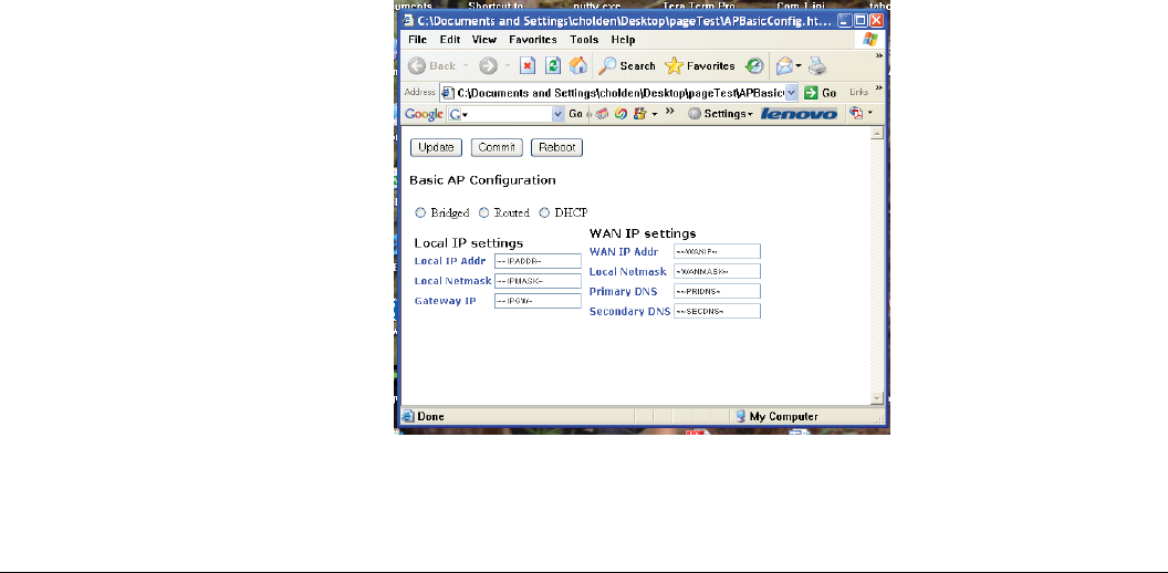
An example of a tagged HTML page:
<HTML><HEAD>
<LINK REL="stylesheet" href="styleSheet.css" type="text/css">
</head><body>
<FORM METHOD=POST>
<p class="headind"><INPUT TYPE="SUBMIT" NAME="UPDATE" VALUE="Update">
  <INPUT TYPE="SUBMIT" NAME="COMMIT" VALUE="Commit">
  <INPUT TYPE="SUBMIT" NAME="RebootButton" VALUE="Reboot"></p>
<p class="topnavg">Basic AP Configuration</p>
<table>
<tr><td colspan=2>
<INPUT type="radio" name="AP_IMODE" ~cAP_IMODE:Bridged~> Bridged 
<INPUT type="radio" name="AP_IMODE" ~cAP_IMODE:Routed~> Routed 
<INPUT type="radio" name="AP_IMODE" ~cAP_IMODE:DHCP~> DHCP 
<tr><td align="top">
<table>
<tr><td colspan=2><a class=topnavg>Local IP settings
<tr><td><a class="header">Local IP Addr
<td><INPUT type="text" id="IPADDR" name="IPADDR" class="text2"
size="20" maxlength="16" value="~~IPADDR~">
<tr><td><a class="header">Local Netmask
<td><INPUT type="text" id="IPMASK" name="IPMASK" class="text2"
size="20" maxlength="16" value="~~IPMASK~">
<tr><td><a class="header">Gateway IP
<td><INPUT type="text" id="IPGW" name="IPGW" class="text2"
size="20" maxlength="16" value="~~IPGW~">
</table>
<td align=top>
<table>
<tr><td colspan=2><a class=topnavg>WAN IP settings
<tr><td><a class="header">WAN IP Addr
<td><INPUT type="text" id="WANIP" name="WANIP" class="text2"
size="20" maxlength="16" value="~~WANIP~">
<tr><td><a class="header">Local Netmask
<td><INPUT type="text" id="WANMASK" name="WANMASK" class="text2"
size="20" maxlength="16" value="~WANMASK~">
<tr><td><a class="header">Primary DNS
<td><INPUT type="text" id="PRIDNS" name="PRIDNS" class="text2"
size="20" maxlength="16" value="~~PRIDNS~">
<tr><td><a class="header">Secondary DNS
<td><INPUT type="text" id="SECDNS" name="SECDNS" class="text2"
size="20" maxlength="16" value="~~SECDNS~">
</table>
</table>
</body></html>
Note the embedded tags for the text boxes and the check boxes. This produces the web page:
13

PRELIMINARY
2.2.2.2 Command Line Usage
The cgiMain program also has command line switches available for use in scripts. This provides convenient access to
stored parameter data, and data updated via web pages. In fact, a web page can start a script as part of a CGI interface,
where the script executes command line versions of cgiMain within the script to perform various functions.
Note that the cache file takes precedence over the flash contents when executing scripts. This is to allow changes to be
made and executed on a temporary basis, and only kept if the desired configuration operates satisfactorily. If you want
to discard cache change, they either ALL have to be discarded, or specific parameters removed. See adding, deleting,
committing, and invalidating cache.
In order to avoid putting /usr/www/cgi-bin into the execution path, a soft link from /bin/cfg to
/usr/www/cgi-bin/cgiMain can be made. All following examples assume the system is configured in this manner. The
basic command line format is as follows:
#cfg [option] [option parameter]
2.2.2.2.1 Adding/modifying a variable in the cache file
To add a variable/value pair to the cache, use the following form:
#cfg –a VAR=VALUE
The variable name must not include spaces, and if the value includes spaces they must be “escaped” (\<char>) or the
value enclosed in quotes (“val”).
2.2.2.2.2 Deleting (removing) a value from the cache file
To delete a variable/value pair from the cache, use the following form:
#cfg –r VAR
The variable name must not include spaces. If the variable does not exist, no error is generated, but no action is
preformed on the cache file. If you remove a variable from the cache file, but do not commit the cache, it will remain in
the permanent flash storage and will be defined upon next bootup.
2.2.2.2.3 Committing the cache file to flash
To commit the contents of the cache file to flash, use the following form:
#cfg –c
This copies the entire contents of the cache file to flash. These values will be preserved through boot and power cycles.
2.2.2.2.4 Invalidating the cache file
In order to invalidate the cache file (re-read it from flash), use the following form:
#cfg –i
This re-reads the contents of the flash and overwrites the cache file with the flash values. This effectively eliminates any
changes made to the cache file without saving them to flash. Use with caution.
2.2.2.2.5 Translating a file
In order to translate a tagged file into a file with values inserted, use the following form:
#cfg –t<index> <filename>
This performs the translation as defined above. Note that the output is put to stdout, so it must be redirected to the
desired destination. The index argument on the option indicates the index value to use for variables with the “#” tag. An
example of usage:
#cfg –t2 /etc/wpa2/open_bss.ap > /tmp/sec2.cfg
This will translate the file /etc/wpa2/openbss.ap, inserting tags and using the value of “_2” as the substation for “#” tags,
and output the file to /tmp/sec2.cfg. The original file is not affected.
14

PRELIMINARY
2.2.2.2.6 Exporting
variables
In order to use the variables in scripts, they need to be exported. The form for doing this is:
#cfg –e
This will output all variables in the form “export VAR=VALUE” for all variables in the cache. To use this in a script
file, you can put the following line in the script:
`cfg –e`
and all variable/value pairs will be in the environment for use.
2.2.2.2.7 Resetting to factory defaults
Resetting to factory defaults is a two step process. First, all current variables must be deleted. This is done by using the
–x option as in the following form:
#cfg -x
This deletes everything in cache and in flash. To reset the default values, execute the apcfg script to re-populate the
defaults. Note that this will be done by the apup script automatically:
#/etc/ath/apcfg
2.3 Environmental Variables
All configuration information is stored in the form of environmental variables that can be displayed by the “cfg –e”
command. Error! Reference source not found. outlines the various environmental variables, their default values (if
applicable), and their effects.
Table 2 AP Environmental Variable
Variable Default Description
ATH_countrycode Identifies the specific regulatory table to use for the country of
interest. Used for testing regulatory compliance.
AP_IPADDR 192.168.1.2 The IP address of the LAN interface; typically assigned to the bridge
interface, because the LAN is always included in the br0 bridge
interface with the ath interfaces.
AP_NETMASK 255.255.255.0 Provides the netmask for the LAN/bridge interface; defines the
number of IP address that can be addressed on the local LAN
interface.
Indicates the mode for the WAN.
bridged Indicates that the WAN interface is included on br0
static Indicates that the WAN interface is to be given the IP
address specified by WAN_IPADDR
WAN_MODE bridged
dhcp Indicates that the WAN interface should get its IP
address from the network it is connected to
WAN_IPADDR 192.168.2.1 IP address for the WAN
WAN_NETMASK 255.255.255.0 Netmask
PRIDNS Primary DNS server IP address
SECDNS Secondary DNS server IP address
WLAN_ON_BOOT N Indicates that the WLAN should be activated as part of the rcS script
on bootup. Only valid with the default parameters specified in the
apcfg file. This will be more useful with future enhancements.
15

PRELIMINARY
Mode for apup execution.
standard Creates a single AP
rootap Creates a single WDS mode AP
client Creates a single WDS station instance.
repeater Creates a WDS repeater containing an AP and client
multi Creates a multiple VAP configuration
multivlan Puts each VAP on a desired VLAN interface
AP_STARTMODE standard
dual On platforms capable of dual concurrent operations set
VAP0 to 2.4 GHz on radio 0, and VAP1 to 5.0 GHz
band on radio 1
AP_RADIO_ID# 0
1
For dual concurrent devices, the radio ID (0 for the “lower” slot, and
1 for the “upper” slot) must be identified for each VAP. When dual
concurrent mode (as opposed to multi mode) is selected, the radio
ID of the first VAP (ath0) is set to 0 and the second VAP (ath1) is
set to 1. In the following entries the radio parameters with the _2
suffix refer to settings for Radio 1 (the “second” radio).
For each VAP, the “mode” of the AP is required. The mode is used
to initialize the VAP. The following are the available modes:
ap Infrastructure access point
sta Simple station VAP (not normally used alone)
ap-wds WDS (4 address frame) format interface that WDS
stations can connect to. See ROOTAP_MAC.
AP_MODE# ap
sta-wds Client WDS interface that connects to an Infrastructure
WDS interface, creating a WDS bridge between the
two devices. Also see ROOTAP_MAC.
AP_PRIMARY_CH
AP_PRIMARH_CH_2
6
40
Indicates the specific channel to set the AP to. Setting to a value of
“11ng” will cause the AP to scan for a free 11g (2.4 GHz) channel.
A value of “11na” will cause the AP to scan for a free 11a (5 GHz)
channel, and a value of “11ng” will scan for a free 11g (2.4 GHz)
channel. Note that the selected channel should match the extension
channel (PLUS or MINUS) mode appropriate for the selected
channel/regulatory mode.
AP_CHMODE
AP_CHMODE_2
11NGHT20
11NAHT40PLUS
Specifies the channel operating mode. See Table 7 Channel
Operating Modes
and section 3.1.3 for details.
ROOTAP_MAC This is used for clients, and will set the preferred MAC address for
the repeater client to associate to. In WDS mode, this is provided to
the client device, and is the MAC address of the WDS VAP on the
root AP device.
AP_VLAN# For each VAP that is associated to a VLAN, this parameter
identifies the VLAN ID for the VAP.
16
Indicates the specific channel to set the AP to. Setting to a value of
pg
“11ng” will cause the AP to scan for a free 11g (2.4 GHz) channel.
gg()
A value of “11na” will cause the AP to scan for a free 11a (5 GHz)
(
c
hannel
,
and a value of “11n
g
” will scan for a free 11
g
(
2.4 GHz
)
,g g()
c
hann
e
l
.
N
o
t
e
that th
e
se
l
ec
t
ed
c
hann
e
l
s
h
ou
l
d
mat
c
h th
e
e
xt
e
n
s
i
o
n
channel (PLUS or MINUS) mode
a
pp
ro
p
riate for the selecte
d
(
c
hannel/re
g
ulator
y
mode.

PRELIMINARY
AP_BRNAME When assigning a VLAN to a VAP, a bridge instance is created for
the VLAN. This identifies the “name” of the bridge.
TXQUEUELEN 1000 Provides the number of transmit descriptors to be allocated for the
ath object. These are shared for all VAPs
SHORTGI
SHORTGI_2
1 Enables the short gating interval.
AMPDUENABLE
AMPDUENABLE_2
1 Enables AMPDU aggregation; applies to all VAPs attached to the
radio.
AMPDUFRAMES
AMPDUFRAMES_2
32 Maximum number of frames to include in the aggregated frame.
Applies to all VAPs attached to the radio.
AMPDULIMIT
AMPDULIMIT_2
50000 Number of bytes for the maximum size of the AMPDU packet.
AMPDUMIN
AMPDUMIN_2
32768 Minimum number of bytes to include in an AMPDU frame.
Setting for channel width management.
0 HT20 only
1 HT20/40
CWMMODE
CWMMODE_2
1
2 HT40 only
Specifies if rate control is to be controlled automatically through the
rate control module.
auto Automatic rate control
RATECTL auto
manual Manually set the rates and retry limits
MANRATE 0x8c8c8c8c This 32 bit hex number encodes the 4 rate table entries that are tried
on the link. This if manual rate control is enabled.
MANRETRIES 0x04040404 Number of retries on each rate interval to attempt before changing.
Only applicable if manual rate control
RX_CHAINMASK
RX_CHAINMASK_2
5 for 3 chain device
3 for 2 chain device
Selects the chain mask to apply to the Receive path. The lowest 3
bits indicate the three antenna chains. This is for a “by 2”
configuration. This setting will override the setting in the EEPROM
of the device.
TX_CHAINMASK
TX_CHAINMASK_2
5 for 3 chain device
3 for 2 chain device
Selects the chain mask to apply to the Transmit path. The lowest 3
bits indicate the transmit chains to include. This is for a “2 by”
configuration. . This setting will override the setting in the
EEPROM of the device.
AP_SSID# Atheros_Xspan_2G
Atheros_Xspan_5G
For the single VAP configurations, or the repeater case, only
AP_SSID is used. Default setting is as indicated.
For multiple VAP configurations, specifies the SSID for each VAP
instance (AP_SSID is VAP 1). If any of the variables are not
defined, the associated VAP will not be created. The AP_SSID_x
variables should be defined in order. If AP_SSID_2 is not defined,
AP_SSID_3 should not be defined. For example, if you are creating
3 VAPs, do not define AP_SSID_4. If you are only creating two
VAPs, do not define AP_SSID_3 and AP_SSID_4.
AP_SECMODE# NONE Selects the security mode for the indicated VAP. One of “WEP”,
“WPA”, “WSC”, or “NONE”
17

PRELIMINARY
AP_SECFILE# Indicates which security configuration file to use for the VAP. See
section 2.1for a description of the configuration files.
AP_VLAN# Used to configure VLAN tags for SSIDs AP_SSID, AP_SSID_2,
AP_SSID_3 and AP_SSID_4 respectively. To configure VLANs.
AP_STARTMODE should be set to multivlan. No default values
are assumed for these configuration items.
WEPKEY_1
WEPKEY_2
WEPKEY_3
WEPKEY_4
These are the 4 WEP keys that are defined in the first 4 slots. Note
that they are the same for ALL VAPs. The length of the key
indicates the strength of the cipher (10 hex digits or 4 characters for
64 bit, 26 hex digits or 13 characters for 128 bit). To indicate ASCII
entry, prepend “s:” to the string
AP_PRIKEY Primary WEP key to use.
AP_WPA# WPA mode. This indicates if WPA-1 or WPA-2 (or both) are to be
used in WPA operations.
AP_CYPHER# Which pairwise ciphers to use for WPA operations. CCMP is AES
encryption where TKIP is WEP. Specifying both indicates auto
selection based on the client.
PSK_KEY# A 9 to 64 bit value used for the PSK generation. This is an ASCII
value.
PSK_KEY_HEX# A 9 to 64 bit value used for the PSK generation. This is an ASCII
value.
AP_AUTH_SVR# IP address of the Radius server used for EAP authentication
methods.
AP_AUTH_PORT# Port number on the Radius server used for EAP authentication login
AP_AUTH_SECRET# Password for logging onto the EAP server for authentication.
WSC_PIN In WSC mode, the PIN number used by the client to authenticate
with the WSC server.
WSC_NAME Simple network name for the AP in WSC mode.
18

PRELIMINARY
2.4 Web Interface
The Atheros AP reference design includes a simplified web interface that can be used to configure the AP in various
modes. These pages provide both configuration and status information. All pages are processed using the cgiMain
program described in section 2.2. Each of these pages contains related information that can be used to configure the AP.
Note that default values are automatically provided to the web interface. These defaults are encoded in the
/etc/ath/apcfg file, and can be modified as required for a particular implementation
Each web page has the buttons:
Update This button accepts the changes on the current page. If the current page is switched, the
updates are NOT saved, so click update if you want to save what you changed on the page.
Reboot This button will reboot the AP. This performs a quick reboot, without closing any open files.
Use with care.
Commit This button commits the parameters in the parameter cache (/tmp/.apcfg) to the flash area.
This saves the parameters through reboot cycles.
Start This starts the AP using the /etc/ath/apup script. This script reads configuration information
from flash/cache, and applies the parameters using the sub-scripts described in the following
sections.
Stop This brings the AP driver and hostapd software down using the /etc/ath/apdown script. This
performs a graceful shutdown of the AP.
In addition, the main network page includes a “factory reset” button that reapplies the parameters encoded in the
/etc/ath/apcfg file.
19
PRELIMINARY
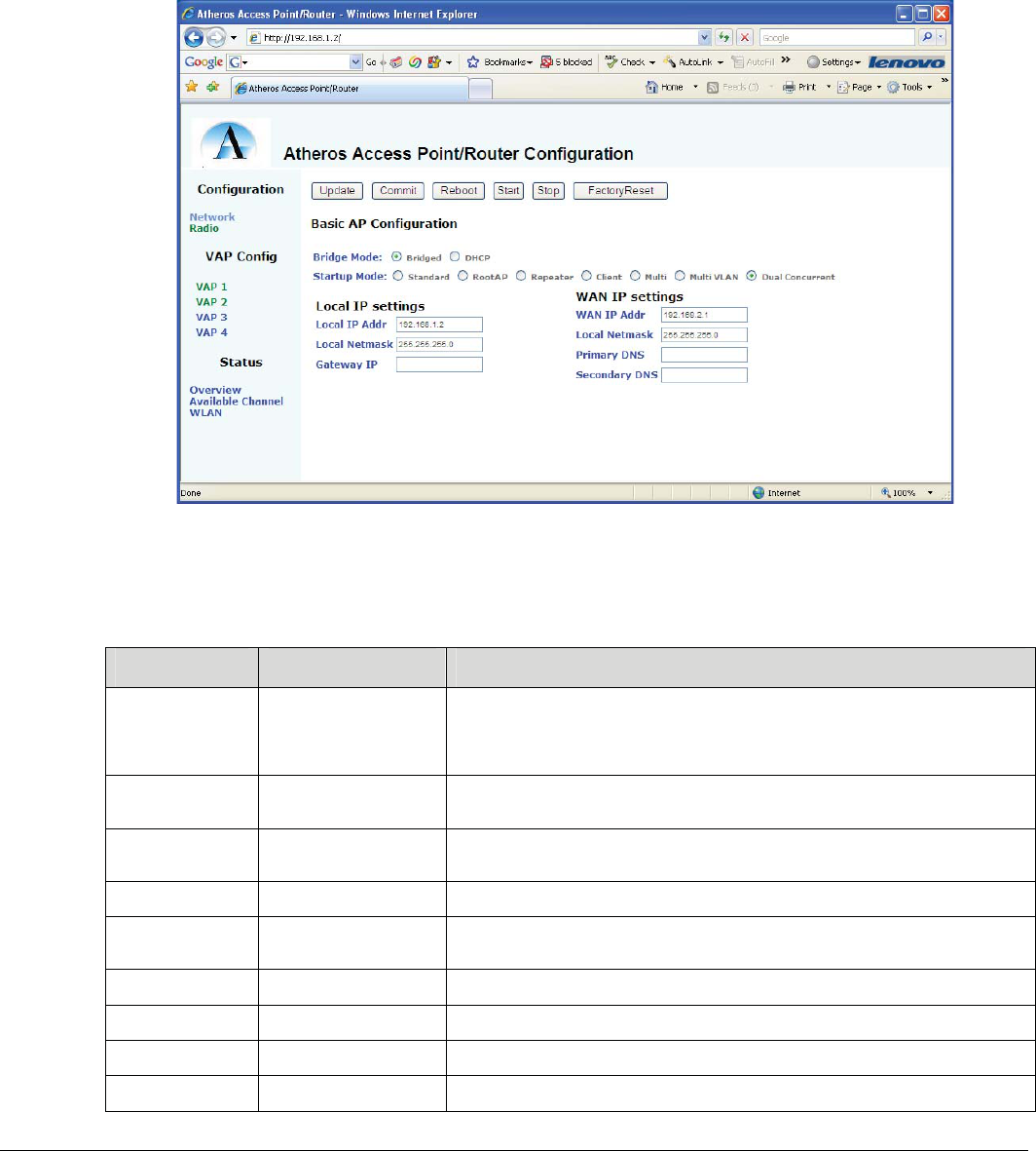
2.4.1 Network Page
The network page is the default initial page, and provides for general network settings. The network page is shown in
Figure 3.
Figure 3 Network Configuration Page
The parameters on this page allow the user to set specific environmental variables with a “point and click” interface:
Table 3 Network Configuration: Page Parameters
Parameter Env Var Description
Bridge Mode WAN_MODE Selects the bridge mode. Bridged means that the WLAN, WAN, and LAN interfaces are all
bridged together, and use the Local IP Addr as the IP address of the device. DHCP means
that the WAN IP address will be set via DHCP. Static means that the WAN interface will use
the IP address and mask specified under WAN IP Settings
Startup Mode AP_STARTMODE Sets the startup mode that the scripts use to initialize the AP. The modes are described in the
parameter description for AP_STARTMODE
LocalIP addr AP_IPADDR This is the IP address used for bridged mode, or it’s the IP address on the LAN interface in
DHCP mode
Local Netmask AP_NETMASK Network mask for the LAN network.
Gateway IP IPGW IP address for the network gateway for Bridged mode, or the gateway on the WAN link for
DHCP mode.
WAN IP Addr WAN_IPADDR IP address for the WAN interface when static mode is used
WAN Netmask WAN_NETMASK Netmask of the WAN interface when static mode is used
Primary DNS PRIDNS Primary DNS server on the WAN interface
Secondary DNS SECDNS Secondary DNS server on the WAN interface
20
PRELIMINARY
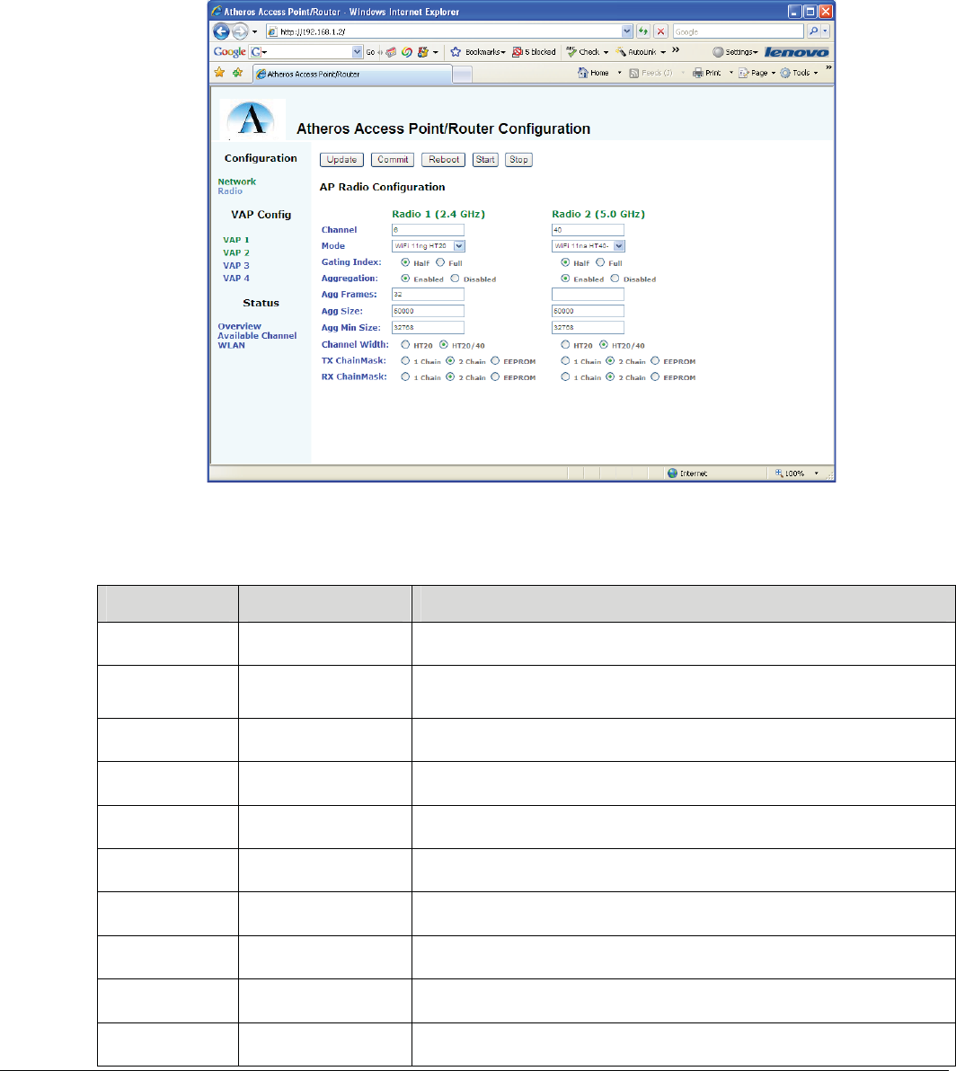
2.4.2 Radio Configuration Page
This page includes the radio parameters for each radio on the AP. This example is for a dual concurrent AP, a single
radio AP would only show a single column. Note that indexed variables here are per Radio as opposed to per VAP.
Figure 4 Radio Configuration Page
Table 4 Radio Configuration: Page Parameters
Parameter Env Var Description
Channel AP_PRIMARY_CH
AP_PRIMARY_CH_2
Indicates the channel selected for the AP. Invalid channels will cause the AP to fail on
startup.
Mode AP_CHMODE
AP_CHMODE_2 Specifies the channel operating mode. See Table 7 Channel Operating Modes
and section 3.1.3 for details
Gating Index SHORT_GI
SHORT_GI_2
Enables half period Gating Index. Disable forces full period gating index.
Aggregation AMPDUENABLE
AMPDUENABLE_2
Enables/Disables aggregation for the radio
Agg Frames AMPDUFRAMES
AMPDUFRAMES_2
Maximum number of frames to include in an aggregate.
Agg Size AMPDULIMIT
AMPDULIMIT_2
Maximum size (in bytes) of an aggregate
Agg Min Size: AMPDUMIN
AMPDUMIN_2
Minimum number of bytes to send as an aggregate
Channel Width CWMMODE
CWMMODE_2
Channel Width Mode (PHY mode). 0 sets to static 20 MHz mode, 1 sets to dynamic 20/40
MHz mode, and 2 sets to static 40 MHz mode.
Tx Chainmask TX_CHAINMASK
TX_CHAINMASK_2
Transmit chainmask. Selections vary between devices
Rx Chainmask RX_CHAINMASK
RX_CHAINMASK_2
Receive chainmask. The number of receive chains to use (not necessarily antennas).
Selections vary between devices.
21
PRELIMINARY
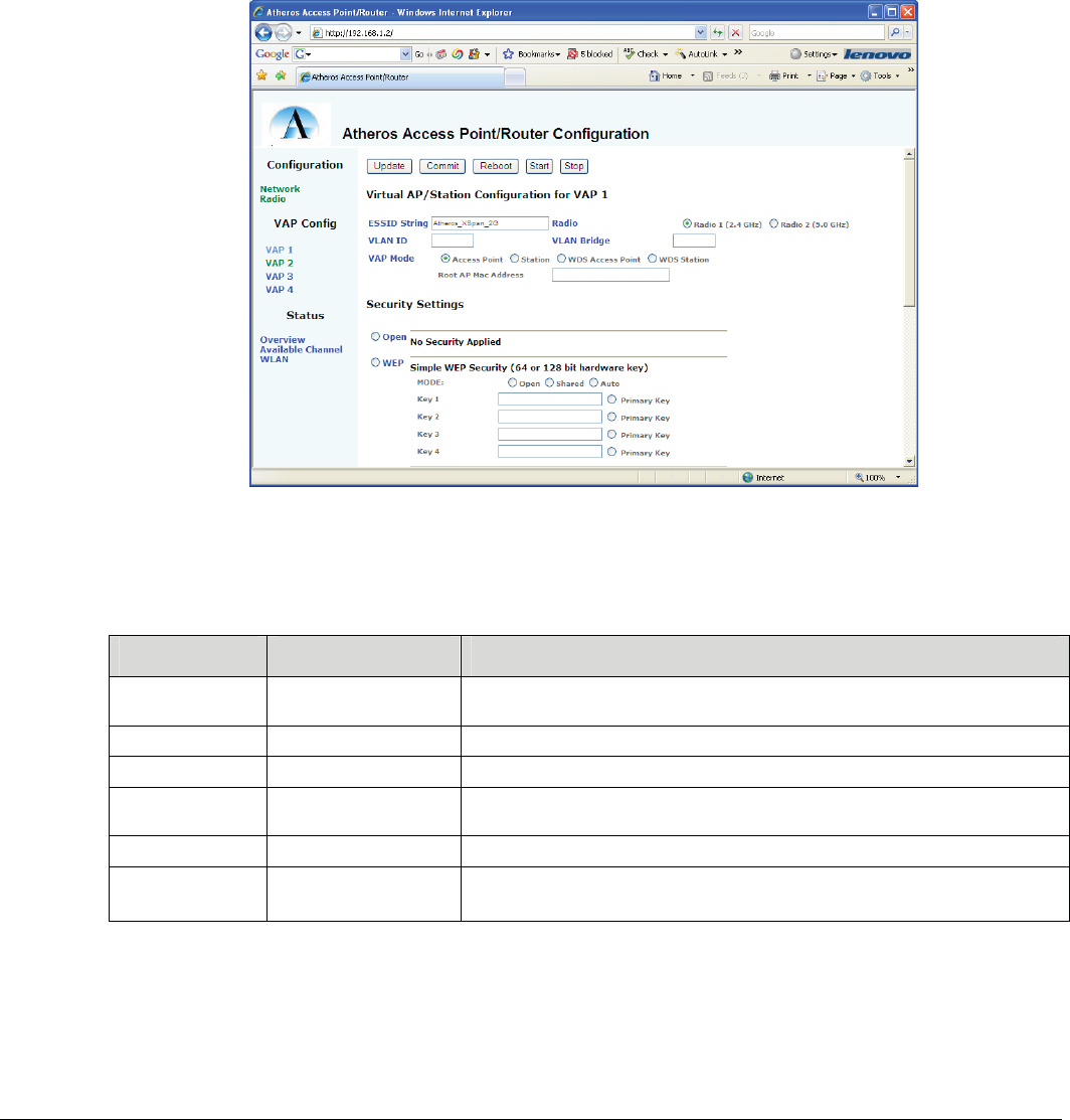
2.4.3 Virtual AP (VAP) Configuration Page
For each VAP (1-4) its individual parameters can be configured through this page. Note that there are selections for
VAP 1-4 on the left panel. These parameters specify things like the ESSID string, which radio to use (for dual
concurrent platforms), VLAN information, initialization mode, and Security Modes.
In this document the various sections of the page are shown in two sections, because a readable screen shot of the entire
page was not possible. The web interface presents all parameters as a single page.
Figure 5 VAP Configuration Page (1 of 2)
Table 5 VAP Configuration: Page Parameters
Parameter Env Var Description
ESSID String AP_SSID# SSID String for the Virtual interface. For Client mode VAPs, this is the ESSID of the BSS to
join to. For AP’s, this is the SSID advertised in the beacon.
Radio AP_RADIO_ID# ID of the radio that this VAP is assigned to. Virtual interface to physical interface mapping.
VLAN ID AP_VLAN# If this VAP is to be included in a VLAN group, the VLAN ID number of the group
VLAN Bridge AP_BRNAME Name of the bridge that is used by this VLAN. Ethernet instances will be added to the bridge
for the VLAN
VAP Mode AP_MODE# Indicates the operating mode for the VAP. See table 1 for details
Root AP MAC
Address
ROOTAP_MAC# Identifies the MAC address of the WDS root when creating a VAP for WDS Client mode.
22
PRELIMINARY
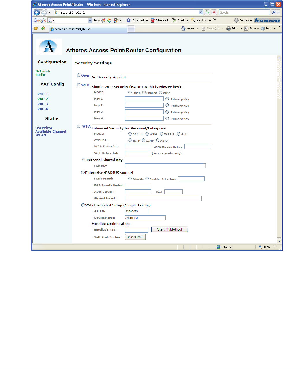
Figure 6 VAP Configuration Page (2 of 2)
23

PRELIMINARY
Table 6 VAP Configuration: Page Parameters
Parameter Env Var Description
Security Modes AP_SECMODE# Vertical set of radio buttons that select the security mode
Open No Security
WEP WEP Security (only 1 instance per radio allowed)
WPA WPA (and WDS) security modes
Security Submodes AP_SECFILE For WPA Security Mode, the following sub modes are defined:
Personal Shared Key User creates a passphrase for authentication. No outside server
required.
Enterprise/Radius Security using 802.1x security modes requiring an authentication
server.
WiFi Protected Setup Security using new WPS standards. AP can be configured from
client.
WEP Mode AP_WEP_MODE Indicates the mode to operate the WEP security in: Open, Shared, or Auto (detect)
WEP Keys WEPKEY_1
WEPKEY_2
WEPKEY_3
WEPKEY_4
WEP keys expressed as either 10, 26, or 52 digit Hex numbers, or after the s: marker, as 5,
13, or 26 character strings.
Primary Key AP_PRIMARY_KEY Indicates the key to use as the primary transmit key.
WPA Mode AP_WPA# Indicates the WPA modes to support: 802.1x (WEP),WPA (WPA-1), WPA2, or Auto
(detect either).
WPA Cypher AP_CYPHER Key policy, either TKIP or CCMP (AES). Auto indicates detect either
WPA Rekey Int AP_WPA_GROUP_REKEY# Interval for group rekey
WPA Master Rekey AP_WPA_GMK_REKEY# Master rekey interval
WEP Rekey Interval AP_WEP_REKEY# When WEP is used with 802.1x mode (not advised), this provides the rekey interval
PSK KEY PSK_KEY PSK value (8-64 characters) to use as a passphrase. String
RSN Preauth AP_RSN_ENA_PREAUTH# Enable RSN preauthorization between APs (for roaming)
RSN Interface AP_WPA_PREAUTH_IF# Interface to use for preauthorization (e.g. eth0)
EAP Reauth Period AP_EAP_REAUTH_PER When using a RADIUS server, the interval to reauthenticate with the server
Auth Server AP_AUTH_SERVER# IP address of the RADIUS server
Auth Port AP_AUTH_PORT# Port number that the RADIUS server is serving on.
Secret AP_AUTH_SECRET# Authentication password for communicating with the RADIUS server
AP PIN WSC_PIN PIN number for static PIN method of WPS setup
Device Name WSC_NAME Name of the device as advertised in PnP messages
Enrollee’s PIN AP_ENROLLEE PIN of the Enrollee when using the remote PIN method
StartPINMethod Button that starts the remote PIN method for enrolling
Soft Push Button Button that emulates the WPS pushbutton on the board.
24
PRELIMINARY
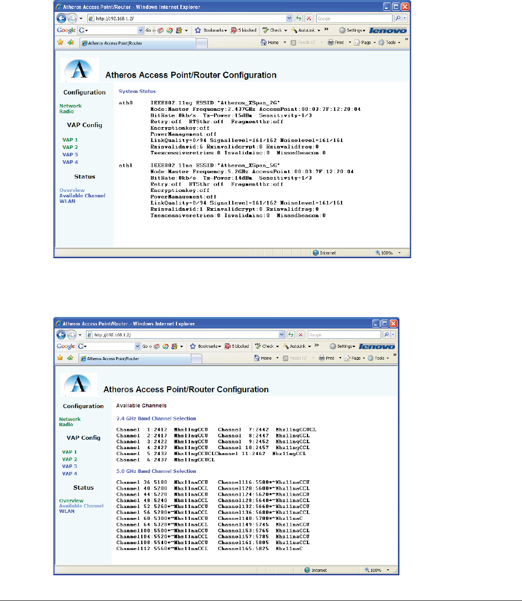
2.4.4 Status Page
This page shows the output of the command “iwconfig” with no parameters
Figure 7 AP Status Page
2.4.5 Channel Page
This page shows the output of the “wlanconfig athx list channel” command. See section 2.5.3 for details.
Figure 8 Channel Page
25
PRELIMINARY
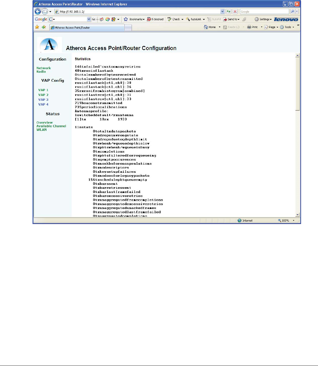
2.4.6 Statistics
This shows the output of the “athstats” program.
Figure 9 Statistics Page
2.5 Command Line Interface
The command line interface consists of setting environmental variables using the configuration tool, and the following
scripts. The recommended approach is to set environmental variables and use the “apup” or “apdown” scripts to ensure
everything is configured correctly.
2.5.1 Shell Scripts
Several shell scripts are provided as examples, or as fully useable implementations. These scripts can be called from
other programs or CGI scripts to implement functionality in the user’s interface.
2.5.1.1 Initialization Scripts
Standard Linux operation requires an initialization script that is run upon bootup. This script, rcS, is kept in the standard
location /etc/rc.d/. All system function initialization scripts, such as network or other services are typically kept in this
directory. Therefore, four scripts have been defined; rcS, rc.bridge, rc.network, and rc.wlan. The rc.* scripts are
intended to be generic and not board specific. These scripts bring up the networking systems in a standard way on all
boards. The rcS script is specific for each board type, depending on its hardware configuration. Any unique modules or
other initialization is performed in this script, keeping the board unique items separate from the general purpose items.
The scripts are described in the following sections.
26

PRELIMINARY
2.5.1.1.1 rcS
Format:
# /etc/rc.d/rcS
This script is the bootup script. It will install any board specific modules, initialize the networking system and bridge,
and optionally bring up the WLAN with the default configuration. It calls the rc.network,rc.bridge, and optionally the
apup script. This script is never executed in any context other than initialization.
2.5.1.1.2 rc.network
Format:
/etc/rc.d/rc.network
This script initializes the main network interfaces on the device. This script requires that the WAN_MODE
environmental variable be set. The WAN_MODE variable controls whether the WAN interface is bridged to the LAN
interface, or if it operates on its own. If set to “static”, the WAN IP is set to the value defined in WAN_IPADDR. If set
to “DHCP”, the WAN address will run the UDHCPC client to obtain its IP address from the network. Finally, if set to
“bridged”, then the WAN is bridged with the LAN and WLAN interfaces.
2.5.1.1.3 rc.bridge
Format
# /etc/rc.d/rc.bridge
The rc.bridge script will setup the bridging function on the device. It is assumed that the LAN interface is always
bridged with the WLAN interfaces, so this interface is always included in the bridge. If the WAN_MODE is set to
“bridged”, then the WAN will also be included in the bridge.
The LAN_DHCP variable indicates whether the DHCP server should be started on the bridge. If set to “y”, then the
UDHCPD daemon is started. The configuration file for the DHCP server is located at /etc/udhcpd.conf.
2.5.1.1.4 rc.wlan
Format:
# /etc/rc.d/rc.wlan up|down
The WLAN modules are initialized or removed using this script. The argument “up” or “down” indicate whether to
install or remove the WLAN driver modules from the system. This script is called by the makeVAP script when it
determines that the ath_pci module is not loaded, and is called by the killVAP script when all VAPs are removed. It is
also called, indirectly, when the reboot command is issued (the inittab will cause the killVAP all command to be
executed on shutdown).
This script does not actually create any VAPs. It simply loads the modules and gets the system ready for VAP creation.
There are no environmental variables that currently are used to configure this script.
2.5.1.2 Driver Operation Scripts
To operate the driver (for example, to create interfaces), three main scripts are provided. These scripts perform the
creation of VAP objects, activation of VAP objects, and destruction of VAP objects. The creation and activation stages
for VAP objects were separated due to the need to create ALL VAP objects before activating ANY VAP objects. This is
required because multiple VAPs will still share the same HAL and ATH driver object. All RF parameters applied to the
VAPS will apply to the single ATH object, so they only need to be set in a single VAP.
27

PRELIMINARY
2.5.1.2.1 makeVAP
Format:
/etc/ath/makieVAP VAP_type SSID IFStr Beacon_Int
VAP_type ap Standard access point
ap-wds WDS root access point
sta Standard Client Mode
sta-wds WDS mode client station
SSID ESSID string for the access point
IFstr Interface configuration string of the form
interface:RF:PriCh:ModeStr
Beacon Int Beacon interval, in milliseconds
This script will create and configure a VAP for the indicated mode VAP_type can be set to AP or station.
Adding the –wds suffix to the VAP type indicates that the VAP is operating in WDS mode. This script
requires that the SSID be specified on the command line – the default is not used. The interface string (IFstr)
was added to support configuration of multiple physical interfaces on the same system. This string has the
form Iface:RF:PriCH:MODE, where Iface is the interface number (0 for WiFi0, 1 for WiFi1), RF indicates
that the RF parameters are to be sent to the VAP to configure the base ATH device, PriCH is the Primary
channel for the operation of the interface, and MODE is the mode name defined in the following table. RF
configuration should only be done on one VAP for a particular interface, since RF parameters apply to any
and all VAPs that are associated with the physical WiFi device. Finally, for multiple BSS configurations the
Beacon Interval can be specified to spread out beacon transmits.
Table 7 Channel Operating Modes
Name Description
11A Standard Legacy OFDM rates in 5 GHz band
11B Standard Legacy DSSS rates in 2.4 GHz band
11G Standard Legacy rates in 2.4 GHz band
11NAHT20 11n rates limited to HT20 MCS rates in 5 GHz band
11NGHT20 11n rates limited to HT20 MCS rates in 2.4 GHz band
11NAHT40PLUS 11n rates up to HT40 MCS rates, using upper extension channel, 5 GHz band
11NAHT40MINUS 11n rates up to HT40 MCS rates, using lower extension channel, 5 GHz band
11NGHT40PLUSԘ 11n rates up to HT40 MCS rates, using upper extension channel, 2.4 GHz band
11NGHT40MINUSķ11n rates up to HT40 MCS rates, using lower extension channel, 2.4 GHz band
An example setup for a dual concurrent configuration would have two makeVAP calls:
# makeVAP ap AP24G 0:RF:8:11NGHT20
# makeVAP ap AP50G 1:RF:52:11NAHT40PLUS
# makeVAP ap AP50Gsec 1:::
This example does the following:
xCreates an AP VAP with ESSID of AP24G on interface 0, configures the RF
to channel 8 in static HT20 mode
xCreates an AP VAP on interface1, configures the RF to channel 52 with
extension channel on the high end.
xCreates a second AP VAP with ESSID of AP50Gsec on interface 1, and
does not configure the RF. This will be on channel 52, since the previous
VAP configured the RF parameters for the physical interface.
The makeVAP script DOES NOT bring the VAP up, or set the security mode. The reason for splitting the
script into a make and activate section is that all VAPs must be created before activating any of them, since
they all share the same ATH device. This constraint is written into the apup script.
Ԙ For 2.4 GHz, HT40 mode must not be set up in an out-of-the-box configuration to meet Wi-Fi certification requirements.
HT40 mode can be user-configurable.
28
Table 7
C
hannel
O
peratin
g
Modes
Na
m
e
D
escr
i
pt
i
on
11A
Standard
L
e
g
ac
y
OF
D
M rates in 5
G
Hz band
11
B
Stan
d
ar
d
Legacy DSSS rates
i
n 2.4 GHz
b
an
d
11G
Standard
L
e
g
ac
y
r
ates in 2.4
G
Hz ban
d
11
N
AHT2
0
1
1n rat
es
limit
ed
t
o
H
T
2
0 M
CS
rates in 5
G
Hz ban
d
11N
G
HT20 11n rates limited to HT20 MCS rates in 2.4 GHz ban
d
11NAHT40PLUS
11n rates up to HT40 MCS rates, us
i
n
g
upper extension channel, 5 GHz band
11NAHT40MINUS
11n rates up to HT40 MCS rates,
usin
g
lower extension channel, 5 GHz band
11NGHT40PLUS
S
Ԙ
11n rates up to HT40 MCS rates, using
u
pper extens
i
on c
h
anne
l
, 2.4 GHz
b
an
d
11n rates up to HT40 MCS rates, usin
g
lo
w
er extension channel, 2.4 GHz ban
d
11NGHT40MINUS
S
ķ
An example setup for a dual concurrent confi
g
uration would have two makeVAP calls:
# makeVAP a
p
AP24G 0:RF:8:11NGHT20
# makeVAP a
p
AP50G 1:RF:52:11NAHT40PLUS
#
makeVAP ap AP50Gsec 1:::

PRELIMINARY
2.5.1.2.2 activateVAP
/etc/ath/activateVAP VAP_id BRG_id SECmode SECparam
VAP_id The specific VAP, as in ath0, ath1, etc.
BRG_id The bridge to add the VAP to, as in br0. Specifying “-“ will
keep the VAP from being added to any bridge.
SECmode Security mode. One of WPA, WEP, WSC, or NONE. This can be left
blank for the default mode of NONE
SECparam Parameter for the security mode. Typically the file containing
the parameters for the selected security mode.
This script activates the VAP by calling “ifconfig vap_id up”, and properly configures the selected security
mode. If the VAP is a station mode VAP, the station scan module will be loaded and activated. All VAPs
must be created prior to calling activateVAP on any VAP. Once this script is executed, VAP
configuration is subject to the restrictions as specified in section 0. For details on security modes and
configuration files, see section 3.2.
2.5.1.2.3 killVAP
/etc/ath/killVAP VAP_id
VAP_id The specific VAP to remove, or “all” to remove all
This script will deconfigure and remove the specified VAP. Optionally, if “all” is specified as the VAP_id, all
VAPs are removed, and all driver modules are unloaded. This is how the apdown script is now implemented.
This script will remove the indicated VAP(s), and remove the associated instances of hostapd,
wpa_supplicant, or wsc. This script does not rely on any environmental variables.
2.5.1.3 Compatibility Scripts
Two scripts have been kept from earlier system operations, apup and apdown. These were kept to allow for backward
compatibility with existing test automation systems existing at Atheros, and possible at customer locations. The
internals have changed significantly, however. Each script should be used with the concept of 1) setting all required
environmental variables, and 2) executing the script.
2.5.1.3.1 apup
Format:
/etc/ath/apup
This is the main script for bringing up various AP configurations that is compatible with the previous methods
for configuring the AP. This script is now completely parameterized, AND SHOULD NOT BE MODIFIED.
Again, the concept of setting environmental variables, then executing this script, is the designed mode of
operation.
The main environmental variable that affects the operation of this script is AP_STARTMODE. This can be
set to standard, repeater, rootap, client, multi or multivlan. The default value is “standard”, which is a single
standard AP instance. See the configuration descriptions in section 3 for the various uses of the
AP_STARTMODE variable.
2.5.1.3.2 apdown
Format:
/etc/ath/apdown
This script is simply a remapping of “killVAP all”. This will remove all VAPs, and unload all driver
modules.
29

PRELIMINARY
2.5.2 Wireless Tools
The Wireless Tools interface is the primary interface used in Linux for configuring and operating the WLAN interface.
The tools themselves are open source, and require specific support through the ioctl interface for the driver. The Atheros
WLAN driver supports these tools “out of the box” without modification. Any version of Wireless tools after version 28
can be used with the Atheros WLAN driver system.
The Wireless Tools use device names to determine which device to configure. In the Atheros driver, there are two
device types that are created when the AP is brought up. The Radio layer, also known as the ATH/HAL layer, is
instantiated as a “wifiN” device, where N is the specific instance starting with zero. The first radio instance, for
example, would be called wifi0. The protocol, or 802.11 layer, will be instantiated as an “athN” device. These devices
are also known as Virtual Access Points, or VAPs. There can be multiple VAPs associated with a single radio, but only
one radio associated with any particular VAP (one to many relationship), as described in the top level architecture. Each
layer controls specific aspects of the operation of the system, so there are specific commands that apply to each
The two main programs of the Wireless tools suite are iwconfig and iwpriv. These commands are used to get or change
specific configuration or operating parameters of the system. Many commands will only be effective before the AP
interface is in the “up” state, so these commands must be performed prior to issuing the “ifconfig up” command to the
interface. The following sections define the valid parameters and commands for each command. Note that the Radio
layer does not support the iwconfig command – this is used exclusively in the protocol layer. Also note that any ifconfig
commands used on the access point must be applied to the protocol layer (ath) device – they have no effect on the Radio
layer.
2.5.2.1 iwconfig
The iwconfig commands are a fixed set of commands that are used to set up and operate the WLAN interface. They are
used in much the same way as ifconfig commands, but are specific to 802.11 device operations. As such, they will
interface to the particular VAP interface. Note that the Radio Layer does not support iwconfig.
ap
#iwconfig athN ap MAC
Selects the specific AP for a client to associate with; used only for WDS client modes in the AP environment.
The only valid argument is the MAC address of the desired AP. The help text will also indicate “off” and
“auto” as choices, but these have no effect other than to disable the selection of a specific MAC address. This is
disabled by default.
#iwconfig ath0 00:03:7f:01:23:45
essid
#iwconfig athN essid “Name of Network”
Sets the name of the BSS as it is provided in the beacon message. While there is no official definition of
“ESSID” in the 802.11 specification, this is the commonly used term for BSS network name in the Linux
environment. The network name can be up to 32 characters in length, and can contain spaces. When running in
AP mode, this is the name of the network as advertised in the beacon message. In STA mode, this is the
network name that the STA will associate with. The name can be quoted (“”) or not, but must be quoted when
including spaces. The ESSID is blank by default. The provided scripts will set the ESSID to
Atheros_Xspan_2G for the first interface, and Atheros_Xspan_5G for the second interface in a dual
concurrent configuration.
#iwconfig ath0 essid AP50_Test
frag
#iwconfig athN frag level
This sets the fragmentation threshold, which is the maximum fragment size. Note that this is not valid for 11n
aggregation operations. The argument level indicates the maximum fragment size, or setting to off disables
fragmentation. Fragmentation is off by default.
#iwconfig ath0 frag 512
30

PRELIMINARY
channel
#iwconfig athN args
Selects the channel for operations. In AP mode, this is the channel that the AP will operate in. For STA
operations, the station will associate to the appropriate AP based on the MAC address setting and the ESSID, so
channel is not important in that mode.
The channel argument will only take channel number. See the freq command for setting the specific frequency.
If an invalid channel is selected, this command will return with an error status. The VAP for this interface
should be destroyed at this point, as it will not be properly configured with a channel. There is no default value.
The provided scripts will bring up the first interface on channel 6 by default, and the second on channel 40 by
default (for dual concurrent operations).
#iwconfig ath0 channel 11
freq
#iwconfig athN freq frequency
Similar to the channel command, this will select the frequency of operation. Note that the frequency value must
be a valid frequency supported by the regulatory requirements table for the device. This command will take
both channel numbers and frequency values. For frequency values, the suffix K, M, or G can be appended to
the value to specify KHz, MHz, or GHz. The values of 2.412G, 2412M, and 2412000000K are all the same
value.
This command will also return an error if the indicated frequency is invalid for the device. The VAP for this
interface should be destroyed at this point, as it will not be properly configured with an operating frequency.
There is no default frequency value.
#iwconfig ath0 freq 5.2G
#iwconfig ath0 freq 40
rate
#iwconfig athN rate rateval|auto
Selects a fixed rate for transmit, or enables the internal rate control logic. When rateval is provided, it specifies
the bit rate desired. Using the M or k suffix can be used to indicate the rate, such as 36M. Specifying auto
instead of a fixed rate will enable the rate control logic internal to the driver. This is the default configuration.
Setting 11n fixed rates is a bit more complicated, and is accomplished using the iwpriv commands
Set11NRates and Set11NRetries. Selecting MCS rates cannot be accomplished through this command.
#iwconfig ath0 rate 54M
retry
Software retry is not supported
rts
#iwconfig athN rts pkt_size
Sets the minimum packet size for which RTS/CTS protection is used. This setting is used to reduce the amount
of arbitration that occurs with short packet transmission, improving throughput. The value of pkt_size is set to
the minimum packet size for which to use the RTS/CTS handshake. Setting pkt_size to a value of 0 disables
RTS/CTS handshake entirely. The use of RTS/CTS in 11n is governed by rate tables and other settings, so this
command may not have the desired effect when using 11n rates.
#iwconfig ath0 rts 64
sens
Receiver sensitivity control is not supported in this driver
31

PRELIMINARY
txpower
#iwconfig athN txpower power_setting
This command will set the transmit power for all packets on the device. This power is limited by the regulatory
limits encoded into the driver, and selected by setting the country code (see iwpriv command setCountry). The
value of power_setting is provided in units of dBm. Setting the power_setting value to off will enable the
internal power control logic for setting power level. Default Tx power levels are dependant on the information
in the selected regulatory table.
#iwconfig ath0 txpower 30
enc
key
#iwconfig athN key [index]key_value
The commands enc and key are synonyms for the same command to set and manage WEP keys. The hardware
will support up to four WEP keys per radio module. The optional index value indicates which key is being
set/activated. The index value can be from 1 to 4.
The key_value parameter can be specified in either hex mode or as an ASCII string. Key values can be
specified for either WEP 64 (40) bit mode, requiring 5 bytes, or WEP 128 (108) bit mode, requiring 13 bytes.
In hexadecimal mode this comes out to 10 or 26 hex digits, respectively. Hex digits are separated in groups of 4
by hyphens. When specifying ASCII keys, the keys will require 5 or 13 characters, respectively. All ASCII
key strings are preceded by the s: indicator.
To turn WEP off, use the off command without index. WEP is automatically turned on when a key is specified.
Specifying a key index without a key value will select that key as the active key.
#iwconfig ath0 key [2] DEAD_BEEF_EA
#iwconfig ath0 key [1] s:AnASCIIkeyVal
#iwconfig ath0 key off
2.5.2.2 iwpriv
The following section defines all of the iwpriv commands available for each layer. Note that there are some duplicate
commands between the layers. It is recommended to use the radio layer commands over the protocol layer command
(wifiN commands over athN commands) when duplication exists.
32

PRELIMINARY
2.5.2.3 Radio
Layer
The radio layer commands are provided to configure the radio layer for ALL VAPs attached to the radio.
Common parameters for the radio include the frequency (channel), the channel width mode (HT 20/40), and
other parameters that apply to radio operations. Note that ALL VAPS attached to the specific radio are
affected by the configurations made to the radio layer.
6MBAck
#iwpriv wifiN 6MBAck 1|0
This command will enable (1) or disable (0) the use of the 6 MB/s (OFDM) data rate for ACK frames. If
disabled, ACK frames will be sent at the CCK rate. The default value is 0. The command has a corresponding
get command to return the current value.
#iwpriv wifi0 6MBAck 1
#iwpriv wifi0 Get6MBAck
wifi0 Get6MBAck:1
AddSWBbo
SWBcnRespT
DMABcnRespT
#iwpriv wifiN SWBcnRespT Response Time
#iwpriv wifiN DMABcnRespT Response Time
#iwpriv wifiN AddSWBb0 Response Time
These settings are used to adjust the calculation of the ready time for the QoS queues. This is used to adjust the
performance of the QoS queues for optimal timing. The parameter Software Beacon Response Time represents
the time, in microseconds, required to process beacons in software. The DMA Beacon Response Time is the
time required to transfer the beacon message from Memory into the MAC queue. Finally, the Additional
Software Beacon Backoff is a “fudge factor” used for final adjustment of the ready time offset.
These parameters are used for experimental adjustment of queue performance. In the AP application they are
not relevant, so they should not be modified. Their default value is zero. Each parameter has a corresponding
get command.
#iwpriv wifi0 SWBcnRespT 1
#iwpriv wifi0 DMABcnRespT 2
#iwpriv wifi0 AddSWBbo 10
#iwpriv wifi0 GetSWBcnRespT
wifi0 GetSWBcnRespT:1
#iwpriv wifi0 GetDMABcnRespT
wifi0 GetDMABcnRespT:2
#iwpriv wifi0 GetAddSWBbo
wifi0 GetAddSWBbo:10
33

PRELIMINARY
AggrProt
AggrProtDur
AggrProtMax
#iwpriv wifiN AggrProt 1|0
#iwpriv wifiN AggrProtDur duration
#iwpriv wifiN AggrProtMax size
These are used to enable RTS/CTS protection on aggregate frames, and control the size of the frames receiving
RTS/CTS protection. These are typically used as a test commands to set a specific condition in the driver. The
AggrProt command is used to enable (1) or disable (0) this function. Default is disabled. The AggrProtDur
setting indicates the amount of time to add to the duration of the CTS period to allow for additional packet
bursts before a new RTS/CTS is required. Default is 8192 microseconds. The AggrProtMax command is used
to indicate the largest aggregate size to receive RTS/CTS protection. The default is 8192 bytes. These
commands have associated get commands.
#iwpriv wifi0 AggrProt 1
#iwpriv wifi0 AggrProtDuration 8192
#iwpriv wifi0 AggrProtMax 8192
#iwpriv wifi0 getAggrProt
wifi0 getAggrProt:1
#iwpriv wifi0 getAggrProtDur
wifi0 getAggrProtDur:8192
#iwpriv wifi0 getAggrProtMax
wifi0 getAggrProtMax:8192
AMPDU
#iwpriv wifiN AMPDU 1|0
This is used to enable/disable transmit AMPDU aggregation for the entire interface. Receiving of aggregate
frames will still be performed, but no aggregate frames will be transmitted if this is disabled. This has a
corresponding get command, and the default value is 1 (enabled).
#iwpriv wifi0 AMPDU 1
#iwpriv wifi0 getAMPDU
wifi0 getAMPDU:1
AMPDUFrames
#iwpriv wifiN AMPDUFrames numFrames
This command will set the maximum number of subframes to place into an AMPDU aggregate frame. Frames
are added to an aggregate until either a) the transmit duration is exceeded, b) the number of subframes is
exceeded, c) the maximum number of bytes is exceeded, or d) the corresponding queue is empty. The subframe
that causes the excess conditions will not be included in the aggregate frame, but will be queued up to be
transmitted with the next aggregate frame.
The default value is 32. This command has a corresponding get command.
#iwpriv wifi0 AMPDUFrames 24
#iwpriv wifi0 getAMPDUFrames
wifi0 getAMPDUFrames:24
AMPDULim
#iwpriv wifiN AMPDULim Byte Limit
This parameter will limit the number of bytes included in an AMPDU aggregate frame. Frames are added to an
aggregate until either a) the transmit duration is exceeded, b) the number of subframes is exceeded, c) the
maximum number of bytes is exceeded, or d) the corresponding queue is empty. The subframe that causes the
excess conditions will not be included in the aggregate frame, but will be queued up to be transmitted with the
next aggregate frame.
The default value of this parameter is 50000. This command has a corresponding get command.
#iwpriv wifi0 AMPDULim 48000
#iwpriv wifi0 getAMPDULim
wifi0 getAMPDULim:48000
34

PRELIMINARY
ANIEna
#iwpriv wifiN ANIEna 0|1
This parameter enables the Automatic Noise Immunity (ANI) processing in both the driver and the baseband
unit. ANI is used to mitigate unpredictable noise spurs in receive channels that are due to the host system that
the device is installed in. This feature was added for CardBus and PCIE devices sold in the retail market that
were not pre-installed in host systems. Most AP implementations will not enable ANI, preferring to limit noise
spurs by design.
#iwpriv wifi0 ANIEna 1
#iwpriv wifi0 GetANIEna
wifi0 GetANIEna:1
AntSwap
DivtyCtl
#iwpriv wifiN AntSwap 1|0
#iwpriv wifiN DivtyCtl AntSel
These commands are used to control antenna switching behavior. For 11n devices, these control which chains
are used for transmit. For Legacy devices, these are used to determine if diversity switching is enabled or
disabled. The AntSwap command is used to indicate when antenna A and B are swapped from the usual
configuration. This will cause Antenna “A” to be used by chain 1 or 2, and Antenna “B” will be used by chain
0. The default is 0, which indicates antennas are not swapped (Antenna “A” to chain 0, Antenna “B” to chain
1,2). The Diversity Control command will enable/disable antenna switching altogether. If Diversity control is
set to Antenna “A” (1) or Antenna “B” (2), the transmitting antenna will not change based on receive signal
strength. If Diversity Control is set to “Variable” (0), then the transmitting antenna will be selected based on
received signal strength. Both commands have associated get commands.
#iwpriv wifi0 AntSwap 1
#iwpriv wifi0 DivtyCtl 2
#iwpriv wifi0 GetAntSwap
wifi0 GetAntSwap:0
#iwpriv wifi0 GetDivtyCtl
wifi0 GetDivtyCtl:0
BcnNoReset
#iwpriv wifiN BcnNoReset 1|0
This controls a debug flag that will either reset the chip or not when a stuck beacon is detected. If enabled (1),
the system will NOT reset the chip upon detecting a stuck beacon, but will dump several registers to the
console. Additional debug messages will be output if enabled, also. The default value is 0. This command has
a corresponding get command.
#iwpriv wifi0 BcnNoReset 1
#iwpriv wifi0 GetBcnNoReset
wifi0 GetBcnNoReset:1
CABlevel
#iwpriv wifiN CABlevel % Multicast
This will set the amount of space that can be used by Multicast traffic in the Content After Beacon (CAB)
queue. CAB frames are also called Beacon Gated Traffic frames, and are sent attached to every beacon. In
certain situations, there may be such a large amount of multicast traffic being transmitted that there is no time
left to send management or Best Effort (BE) traffic. TCP traffic gets starved out in these situations. This
parameter controls how much of the CAB queue can be used by Multicast traffic, freeing the remainder for BE
traffic. The default value of this parameter is 80 (80% Multicast), and the command has a corresponding get
command
#iwpriv wifi0 CABlevel 50
#iwpriv wifi0 getCABlevel
wifi0 getCABlevel:50
35

PRELIMINARY
CCKTrgLow
CCKTrgHi
#iwpriv wifiN CCKTrgLow Low Threshold
#iwpriv wifiN CCKTrgHi High Threshold
These commands control the CCK PHY Error/sec threshold settings for the ANI immunity levels. A PHY error
rate below the low trigger will cause the ANI algorithm to lower immunity thresholds, and a PHY error rate
exceeding the high threshold will cause immunity thresholds to be increased. When a limit is exceed, the ANI
algorithm will modify one of several baseband settings to either increase or decrease sensitivity. Thresholds are
increased/decreased in the following order:
Increase:
raise Noise Immunity level to MAX from 0, if Spur Immunity level is at MAX;
raise Noise Immunity level to next level from non-zero value;
raise Spur Immunity Level;
(if using CCK rates) raise CCK weak signal threshold + raise FIR Step level;
Disable ANI PHY Err processing to reduce CPU load
Decrease:
lower Noise Immunity level;
lower FIR step level;
lower CCK weak signal threshold;
lower Spur Immunity level;
The default values for these settings are 200 errors/sec for the high threshold, and 100 errors/sec for the low
threshold.
Each of these commands has a corresponding get command.
#iwpriv wifi0 CCKTrgLow 80
#iwpriv wifi0 CCKTrgHi 220
#iwpriv wifi0 GetCCKTrgLow
wifi0 GetCCKTrgLow:100
#iwpriv wifi0 GetCCKTrgHi
wifi0 GetCCKTrgHi:200
CCKWeakThr
#iwpriv wifiN CCKWeakThr 1|0
This command will select either normal (0) or weak (1) CCK signal detection thresholds in the baseband. This
is used to toggle between a more sensitive threshold and a less sensitive one, as part of the Adaptive Noise
Immunity (ANI) algorithm. The actual settings are set at the factory, and are stored in EEPROM. If ANI is
enabled, this parameter may be changed independent of operator setting, so this command may be overridden
during operation.
The default value for this parameter is 0. This command has a corresponding Get command.
#iwpriv wifi0 CCKWeakThr 1
#iwpriv wifi0 GetCCKWeakThr
wifi0 GetCCKWeakThr:1
chainmasksel
#iwpriv wifiN chainmasksel 1|0
This command enables (1) automatic chainmask selection. This feature allows the system to select between 2
and 3 transmit chains, depending on the signal quality on the channel. For stations that are distant, using 3
chain transmit allows for better range performance. The default value of this parameter is 0 (disabled). This
command has a corresponding get command.
#iwpriv wifi0 chainmasksel 1
#iwpriv wifi0 get_chainmasksel
wifi0 get_chainmasksel:0
36

PRELIMINARY
CWMIgnExCCA
#iwpriv wifiN CWMIgnExCCA 1|0
This command allows the system to ignore the clear channel assessment (CCA) on the extension channel for
11n devices operating in HT 40 mode. Normally, to transmit, the device will require no energy detected on
both the control and extension channels for a minimum of a PIFS duration. This control will allow for ignoring
energy on the extension channel. This is not in conformance with the latest draft of the 802.11n specifications,
and should only be used in a test mode. The default value for this parameter is 0 (do NOT ignore extension
channel CCA). This command has a corresponding get command.
#iwpriv wifi0 CWMIgnExCCA 1
#iwpriv wifi0 GetCWMIgnExCCA
wifi0 GetCWMIgnExCCA:0
FIRStepLvl
#iwpriv wifiN FIRStepLvl level
This command will adjust the FIR filter parameter that determines when a signal is in band for weak signal
detection. Raising this level reduces the likelihood of adjacent channel interferers causing a large number of
(low RSSI) PHY errors, lowering the level allows easier weak signal detection for extended range. This
parameter is also modified by the ANI algorithm, so this may be change dynamically during operation, usually
in steps of single units. The default value for this parameter is 0. The command has a corresponding Get
command, but this returns the initialization (starting) value, and not the value that is currently in the operating
registers.
#iwpriv wifi0 FIRStepLvl 1
#iwpriv wifi0 GetFIRStepLvl
wifi0 GetFIRStepLvl:0
ForceBias
ForBiasAuto
#iwpriv wifiN ForBiasAuto 1|0
#iwpriv wifiNForceBias Bias
This command activates the “force bias” feature. This is used as a workaround to a directional sensitivity issue
in the AR5133 PHY chip in 2.4 GHz bands. ForBiasAuto will automatically select the bias level depending on
the selected frequency. ForceBias will set the bias to a value between 0 and 7. These commands are only
available when the driver is compiled with the #define ATH_FORCE_BIAS parameter defined. Even when this
switch is enabled, the default values for both parameters are 0 (disabled). This should only be enabled if the
sensitivity issue is actually present.
The command has corresponding Get commands
#iwpriv wifi0 ForBiasAuto 1
#iwpriv wifi0 ForceBias 2
#iwpriv wifi0 GetForBiasAuto
wifi0 GetForBiasAuto:0
#iwpriv wifi0 GetForceBias
wifi0 GetForceBias:1
37

PRELIMINARY
HALDbg
#iwpriv wifiN HALDbg debug level
Used to set the debug level in the HAL code. This can be modified “on the fly” as required. The HAL must be
built with the AH_DEBUG parameter defined for this command to be available; otherwise it is conditionally
compiled out. The value provided is a bitmask selecting specific categories of debug information to select
from. Note that some categories will produce copious amounts of output, and should be used sparingly for a
few seconds.
Table 8 HAL Debug Flags
Symbolic Name Enable Bit Description
HAL_DBG_RESET 0x00000001 Information pertaining to reset processing and initialization
HAL_DBG_PHY_IO 0x00000002 PHY read/write states
HAL_DBG_REG_IO 0x00000004 Register I/O, including all register values. Use with caution
HAL_DBG_RF_PARAM 0x00000008 RF Parameter information, and table settings.
HAL_DBG_QUEUE 0x00000010 Queue management for WMM support
HAL_DBG_EEPROM_DUMP 0x00000020 Large dump of EEPROM information. System must be compiled with the EEPROM_DUMP
conditional variable defined
HAL_DBG_EEPROM 0x00000040 EEPROM read/write and status information
HAL_DBG_NF_CAL 0x00000080 Noise Floor calibration debug information
HAL_DBG_CALIBRATE 0x00000100 All other calibration debug information
HAL_DBG_CHANNEL 0x00000200 Channel selection and channel settings
HAL_DBG_INTERRUPT 0x00000400 Interrupt processing. WARNING: this produces a LOT of output, use in short bursts.
HAL_DBG_DFS 0x00000800 DFS settings
HAL_DBG_DMA 0x00001000 DMA debug information
HAL_DBG_REGULATORY 0x00002000 Regulatory table settings and selection
HAL_DBG_TX 0x00004000 Transmit path information
HAL_DBG_TXDESC 0x00008000 Transmit descriptor processing
HAL_DBG_RX 0x00010000 Receive path information
HAL_DBG_RXDESC 0x00020000 Receive descriptor processing
HAL_DBG_ANI 0x00040000 Debug information for Automatic Noise Immunity (ANI)
HAL_DBG_BEACON 0x00080000 Beacon processing and setup information
HAL_DBG_KEYCACHE 0x00100000 Encryption Key management
HAL_DBG_POWER_MGMT 0x00200000 Power and Tx Power level management
HAL_DBG_MALLOC 0x00400000 Memory allocation
HAL_DBG_FORCE_BIAS 0x00800000 Force Bias related processing
HAL_DBG_POWER_OVERRIDE 0x01000000 TX Power Override processing
HAL_DBG_UNMASKABLE 0xFFFFFFFF Will be printed in all cases if AH_DEBUG is defined.
This command has a corresponding get command. Its default value is 0 (no debugging on), but this does not
disable the “Unmaskable” prints.
#iwpriv wifi0 HALDbg 0x84c03
#iwpriv wifi0 getHALDbg
wifi0 getHALDbg:50
38

PRELIMINARY
HTEna
#iwpriv wifiN HTEna 1|0
This command is used to enable (1) or disable (0) 11N (HT) data rates. This is normally only used as a test
command. The parameter is set to 1 (enabled) by default. The command has a corresponding Get command.
#iwpriv wifi0 HTEna 1
#iwpriv wifi0 GetHTEna
wifi0 GetHTEna:1
NoiseImmLvl
#iwpriv wifiN NoiseImmLvl level
This will select a specific noise immunity level parameter during initialization. This command only has effect
prior to creating a specific HAL instance, and should be done only during system initialization. Each noise
immunity level corresponds to a specific set of baseband parameters used to adjust the sensitivity of the
baseband receiver. The values are set at the factory, and are selected as a “set” by this parameter.
This level is also controlled by the ANI algorithm, so that the initial immunity level will be modified during
operation to select the optimal level for current conditions. The default value for this parameter is 4, and should
not be changed unless there is a specific reason. The command has a corresponding get command.
#iwpriv wifi0 NoiseImmLvl 3
#iwpriv wifi0 GetNoiseImmLvl
wifi0 GetNoiseImmLvl:4
OFDMTrgLow
OFDMTrgHi
#iwpriv wifiN OFDMTrgLow Low Threshold
#iwpriv wifiN OFDMTrgHi High Threshold
These commands control the OFDM PHY Error/sec threshold settings for the ANI immunity levels. A PHY
error rate below the low trigger will cause the ANI algorithm to lower immunity thresholds, and a PHY error
rate exceeding the high threshold will cause immunity thresholds to be increased. When a limit is exceed, the
ANI algorithm will modify one of several baseband settings to either increase or decrease sensitivity.
Thresholds are increased/decreased in the following order:
Increase:
raise Noise Immunity level to MAX from 0, if Spur Immunity level is at MAX;
raise Noise Immunity level to next level from non-zero value;
raise Spur Immunity Level;
(if using CCK rates) raise CCK weak signal threshold + raise FIR Step level;
Disable ANI PHY Err processing to reduce CPU load
Decrease:
OFDM weak signal detection on + increased Spur Immunity to 1;
lower Noise Immunity level;
lower FIR step level;
lower CCK weak signal threshold;
lower Spur Immunity level;
OFDM weak signal detection on, with the existing Spur Immunity level 0
The default values for these settings are 500 errors/sec for the high threshold, and 200 errors/sec for the low
threshold.
Each of these commands has a corresponding get command.
#iwpriv wifi0 OFDMTrgLow 100
#iwpriv wifi0 OFDMTrgHi 550
#iwpriv wifi0 GetOFDMTrgLow
wifi0 GetOFDMTrgLow:200
#iwpriv wifi0 GetOFDMTrgHi
wifi0 GetOFDMTrgHi:500
39

PRELIMINARY
OFDMWeakDet
#iwpriv wifiN OFDMWeakDet 1|0
This command will select normal (0) or weak (1) OFDM signal detection thresholds in the baseband register.
The actual thresholds are factory set, and are loaded in the EEPROM. This parameter corresponds to the
initialization value for the ANI algorithm, and is only valid prior to system startup. The default value for this
parameter is 1 (detect weak signals). The corresponding Get command will return the initialization value only.
#iwpriv wifi0 OFDMWeakDet 0
#iwpriv wifi0 GetOFDMWeakDet
wifi0 GetOFDMWeakDet:1
RSSIThrLow
RSSIThrHi
#iwpriv wifiN RSSIThrLow far threshold
#iwpriv wifiN RSSIThrHi near threshold
These settings are used to determine the relative distance of the AP from the station. This is used to determine
how the ANI immunity levels are selected. If the average beacon RSSI of beacons from the AP is greater than
RSSIThrHi, then the STA is determined to be at close-range. If the average beacon RSSI of beacons from the
AP is less than RSSIThrHi, but greater than RSSIThrLow, then the STA is determined to be at mid-range. If the
average beacon RSSI of beacons from the AP is less than RSSIThrLow, then the STA is determined to be at
long-range. The default values 40 for the high (near) threshold and 7 for the low (far) threshold. This
command has corresponding Get commands
#iwpriv wifi0 RSSIThrLow 6
#iwpriv wifi0 RSSIThrHi 45
#iwpriv wifi0 GetRSSIThrLow
wifi0 GetRSSIThrLow:7
#iwpriv wifi0 GetRSSIThrHi
wifi0 GetRSSIThrHi:40
setCountryID
setCountry
#iwpriv wifiN setCountryID Country ID Num
#iwpriv wifiN setCountry Country String
These are used to set the AP to the regulatory requirements of the indicated country. The SetCountryID
command takes an integer value that represents the country, such as 840 for US. The setCountry
command takes a string argument that includes the two character country string, plus “I” for indoor or
“O” for outdoor. The default value for country ID is 0 for debug, so that during initialization the country ID
must be defined. This is a requirement for the final system configuration. See Table 14 Country Code
Definition
for a full list of country IDs and strings.
Each command has a corresponding get command.
#iwpriv wifi0 setCountryID 840
#iwpriv wifi0 setCountry USI
#iwpriv wifi0 getCountryID
wifi0 getCountryID:840
#iwpriv wifi0 getCountry
wifi0 getCountry:USI
SpurImmLvl
#iwpriv wifiN SpurImmLvl level
This command will set the Spur Immunity level, corresponding to the baseband parameter, cyc_pwr_thr1 that
determines the minimum cyclic RSSI that can cause OFDM weak signal detection. Raising this level reduces
the number of OFDM PHY Errs/s (caused due to board spurs, or interferers with OFDM symbol periodicity),
lowering it allows detection of weaker OFDM signals (extending range). As with most ANI related commands,
this value is the initialization value, not the operating value. The default value for this command is 2. This
command has corresponding get commands.
40

PRELIMINARY
#iwpriv wifi0 SpurImmLvl 3
#iwpriv wifi0 GetSpurImmLvl
wifi0 GetSpurImmLvl:2
txchainmask
rxchainmask
#iwpriv wifiN txchainmask mask
#iwpriv wifiN rxchainmask mask
These parameters set the transmit and receive chainmask values. For MIMO devices, the chainmask indicates
how many streams are transmitted/received, and which chains are used. For some Atheros devices up to 3
chains can be used, while others are restricted to 2 or 1 chain. It’s important to note that the maximum number
of chains available for the device being used. For dual chain devices, chain 2 is not available. Similarly, single
chain devices will only support chain 0. The chains are represented in the bit mask as follows:
Chain 0 0x01
Chain 1 0x02
Chain 2 0x04
Selection of chainmask can affect several performance factors. For a 3 chain device, most of the time an RX
chainmask of 0x05 (or 0x03) is used for 2x2 stream reception. For near range operations, a TX chainmask of
0x05 (or 0x03) is used to minimize near range effects. For far range, a mask of 0x07 is used for transmit.
The default chainmask values are stored in EEPROM. This iwpriv command will override the current
chainmask settings. These commands have corresponding get commands
#iwpriv wifi0 txchainmask 0x05
#iwpriv wifiN rxchainmask 0x05
#iwpriv wifiN get_txchainmask
wifi0 get_txchainmask:5
#iwpriv wifiN get_rxchainmask mask
wifi0 get_rxchainmask:5
TXPowLim
#iwpriv athN TXPowLim limit
This command will set the current Tx power limit. This has the same effect as the iwconfig ath0 txpower
command. The Tx power will be set to the minimum of the value provided and the regulatory limit. Note that
this value may be updated by other portions of the code, so the effect of the value may be temporary. The value
is in units of 0.5 db increments. This command has a corresponding get command, and its default value is 0.
#iwpriv ath0 TXPowLim 30
#iwpriv ath0 getTxPowLim
wifi0 getTxPowLim:30
TXPwrOvr
#iwpriv athN TXPwrOvr overrideLimit
This command is used to override the transmit power limits set by iwconfig or the TXPowLim command. This
is used for testing only, and is still limited by the regulatory power. A value of 0 disables this override. The
command has a corresponding get command, and its default value is 0.
#iwpriv ath0 TXPowOvr 30
#iwpriv ath0 getTxPowOvr
wifi0 getTxPowOvr:30
2.5.2.4 Protocol Layer
The Protocol Layer (or 802.11 layer) commands are used to configure settings that are made per VAP. These
include such things as security modes, QoS settings, WMM parameters, and any other setting that is specific
to the specific VAP vice the radio. These commands are grouped according to general categories to keep
associated commands in the same section.
41

PRELIMINARY
2.5.2.5 WMM
related
WMM commands are provided to manage the WMM link settings. In order to specify the proper parameters,
each command must specify the access category (AC) and mode (either STA or AP).
Table 9 Access Categories and Modes
Value Symbol Description
Access Categories
0 AC_BE Best Effort
1 AC_BK Background
2 AC_VI Video
3 AC_VO Voice
Mode Parameter
0 AP AP Mode – update AP WMM table
1 STA Station Mode – update Station WMM tables
The parameters accessible for WMM operations are specified in the WMM (including WMM Power Save)
Specification. These parameters control how the time slots or “TXOPs” are metered out for each traffic stream.
The parameters accessible in the Atheros Fusion driver are as follows:
Table 10 WMM Parameter Definitions
Parameter Units Description
ACM 1|0 Admission Control Mandatory. This flag indicates that Admission Control
is required for the specified AC. A value of 1 indicates that Admission
control is required, 0 indicates not required.
AIFSN slots This is the number of time slots inside the Arbitration Interframe space to be
used. The minimum value is 2.
logCWmin 12 minlog
min CW
CW Minimum backoff timer limit. This is specified in “log” units, where the
actual value of CWmin is expressed as shown
logCWmax 12 maxlog
max CW
CW Maximum backoff timer limit. This is specified in “log” units, where the
actual value of CWmax is expressed as shown
TXOPlimit 32 us Maximum duration for a TXOP as negotiated with the station. A value of 0
for this parameter indicates that a single MSDU or MMPDU in addition to a
possible RTS/CTS or CTS to itself may be transmitted at any PHY rate for
each TXOP.
NoACK Policy 1|0 A value of 1 indicates that there is no acknowledgement expected for the
frame, where a value of 0 indicates that an ACK frame is expected.
acm
#iwpriv athN acm AC Mode value
The ACM value for each access category is set using the acm command. The AC and Mode values must
be set for this command. The value is the ACM value (see Table 9 Access Categories and Modes
) for the specific access category. This command has a corresponding get command that returns the current
setting for the indicated AC and mode.
#iwpriv ath0 acm 0 1 1
#iwpriv ath0 get_acm 0 1
ath0 get_acm:1
42

PRELIMINARY
aifs
#iwpriv athNaifs AC Mode Value
This WMM command sets the AIFSN WMM parameter for either the AP or Station parameter set. This
parameter controls the frame spacing in WMM operations. The command takes 3 parameters: The first
value, AC, is the access class value. The second value indicates whether the command is to be applied
to the AP or Station tables, which are kept separately. Finally, the third parameter is the AIFSN value (see
Table 9 Access Categories and Modes
). This parameter has a corresponding get command, which requires the AC and Mode as arguments.
#iwpriv ath0 aifs 0 0 3
#iwpriv ath0 get_aifs 0 0
ath0 get_aifs:3
cwmax
#iwpriv athN cwmax AC Mode value
This command sets the CWmax WMM parameter for either the AP or station parameter set. The cwmax
command is a WMM command that must have the AC and Mode specified. The value is CWmax in units
as described in Table 9 Access Categories and Modes
. This command has a corresponding get command.
#iwpriv ath0 cwmax 3 1 4
#iwpriv ath0 get_cwmax 3 1
ath0 get_cwmax:4
cwmin
#iwpriv athN cwmin AC Mode value
This command sets the CWmin WMM parameter for either the AP or station parameter set. The cwmax
command is a WMM command that must have the AC and Mode specified. The value is CWmin in units
as described in Table 9 Access Categories and Modes
. This command has a corresponding get command which requires the AC and Mode to be specified.
#iwpriv ath0 cwmin 3 1 2
#iwpriv ath0 get_cwmin 3 1
ath0 get_cwmin: 2
noackpolicy
#iwpriv athN noackpolicy AC Mode 0|1
This command sets the No ACK policy bit in the WMM parameter set for either the AP or station. The
noackpolicy command is a WMM command that must have the AC and Mode specified. The value either sets
the policy to “no ACK sent” (1) or “send ACK” (0). This command has a corresponding get command.
#iwpriv ath0 noackpolicy 0 1 1
#iwpriv ath0 get_noackpolicy 0 1
ath0 get_noackpolicy:1
txoplimit
#iwpriv athN txoplimit AC Mode limit
This command will set the TXOP limit, described in Table 9 Access Categories and Modes
. The AC and Mode is as described at the beginning of this section. This command has a corresponding get
command.
#iwpriv ath0 txoplimit 1 0 10
#iwpriv ath0 get_txoplimit 1 0
ath0 get_txoplimit:10
wmm
#iwpriv athN wmm 1|0
43

PRELIMINARY
This command will enable or disable WMM capabilities in the driver. The WMM capabilities perform special
processing for multimedia stream data including voice and video data. This command has a corresponding get
command, and its default value is 1 (WMM enabled).
#iwpriv ath0 wmm 1
#iwpriv ath0 get_wmm
ath0 get_wmm:1
2.5.2.6 Security Related
These commands relate to the security subsystem, and also are specific interfaces required by the hostapd and
wpa_supplicant programs. Some of these may not be directly security related, but are included here due to their
use by the authenticator and supplicant
authmode
#iwpriv athN authmode mode
This command selects the specific authentication mode to configure the driver for. This command is also used
by host_apd to configure the driver when host_apd is used as an authenticator. The mode values are:
Value Description
0 None specified
1 Open Authentication
2 Shared Key (WEP) Authentication
3 802.1x Authentication
4 Auto Select/accept authentication (used by host_apd)
5 WPA PSK with 802.1x PSK
The user will normally not use these commands. These commands have an associated get command, and its
default value is 0.
#iwpriv ath0 authmode 2
#iwpriv ath0 get_authmode
ath0 get_authmode:2
countermeasures
#iwpriv athN countermeasures 1|0
Enables or disables WPA/WPA2 countermeasures. Countermeasures perform additional processing on
incoming authentication requests to detect spoof attempts, such as repeating authentication packets. A value of
1 enables countermeasures, and 0 disables them. This command has a corresponding get command.
#iwpriv ath0 countermeasures 1
#iwpriv ath0 get_countermeasures
ath0 get_countermeasures:1
dropunencrypted
#iwpriv athN dropunencrypted 0|1
This command enables or disables dropping of unencrypted non-PAE frames received. Passing a value of 1
enables dropping of unencrypted non-PAE frames. Passing a value of 0 disables dropping of unencrypted non-
PAE frames. This command has a corresponding get command, and its default value is zero.
#iwpriv ath0 dropunencrypted 1
#iwpriv ath0 get_dropunencry
ath0 get_dropunencry:1
keymgtalgs
#iwpriv athN keymgtalgs algs
This command is used by host_apd in managing WPA keys. This is essentially the same as the WPA
command, which is a combination of bits indicating different capabilities. The algs supported are as follows:
Value Alg
0 WPA_ASE_NONE
1 WPA_ASE_8021X_UNSPEC
44

PRELIMINARY
2 WPA_ASE_8021X_PSK
The command is a combination of the above, so a value of 3 indicates both unspec and PSK support. The
command has a corresponding get command.
#iwpriv ath0 keymgtalgs 3
#iwpriv ath0 get_keymgtalgs
ath0 get_keymgtalgs:3
mcastcipher
#iwpriv athN mcastcipher cipher
Used mainly by the hostapd daemon, this command will set the cipher used for multicast. The value of cipher is
one of the following:
Value Cipher Type
0 IEEE80211_CIPHER_WEP
1 IEEE80211_CIPHER_TKIP
2 IEEE80211_CIPHER_AES_OCB
3 IEEE80211_CIPHER_AES_CCM
5 IEEE80211_CIPHER_CKIP
6 IEEE80211_CIPHER_NONE
The iwpriv command sets the cipher type for the VAP. This is required to support operation of the host_apd
authenticator. It has no default value, and the command has a corresponding get command.
#iwpriv ath0 mcastcipher 1
#iwpriv ath0 get_mcastcipher
ath0 get_mcastcipher:1
mcastkeylen
#iwpriv athN mcastkeylen length
This is only valid for WEP operations. This command is used to set the key length of the WEP key. Key
lengths of 5 (40 bits) or 13 (104 bits) are the only valid values, corresponding to 64 or 128 bit WEP encoding,
respectively. This command has no default value. This command has a corresponding get command.
#iwpriv ath0 mcastkeylen 5
#iwpriv ath0 get_mcastkeylen
ath0 get_mcastcipher:5
privacy
#iwpriv athN privacy 1|0
The privacy flag is used to indicate WEP operations. This is not normally used by an application other than
host_apd. WEP operations are normally configured through the appropriate iwconfig command. This
command has a corresponding get command, and its default value is 0.
#iwpriv ath0 privacy 1
#iwpriv ath0 get_privacy
ath0 get_privacy:1
rsncaps
#iwpriv athN rsncaps flags
This command sets the RSN capabilities flags. The only valid capability flag is 0x01, RSN_CAP_PREAUTH,
which is used to configure the AP for preauthorization functionality. This is normally used only by host_apd
when configuring the VAP. This command has a corresponding get command.
#iwpriv ath0 rsncaps 0x01
#iwpriv ath0 get_rsncaps
ath0 get_rsncaps:1
45

PRELIMINARY
setfilter
#iwpriv athN setfilter filter
This command allows an application to specify which management frames it wants to receive from the VAP.
This will cause the VAP to forward the indicated frames to the networking stack. The filter is a set of bits with
the following values:
Bit Frame type to forward
0x01 Beacon
0x02 Probe Request
0x04 Probe Response
0x08 Association Request
0x10 Association Response
0x20 Authentication
0x40 Deauthentication
0x80 Disassociation
0xff ALL
This command is normally used by host_apd for configuring the VAP. It does NOT have a corresponding get
command.
#iwpriv ath0 setfilter 0x24
setiebuf
getiebuf
These commands are used by an application to set/get application Information Elements into/from various
frame types. The ieee80211req_getset_appiebuf structure is passed as an argument to the ioctl. There is no
command line equivalent for these commands, but the command does show up as a valid iwpriv command. The
definition of the required data structure is as follows:
struct ieee80211req_getset_appiebuf {
u_int32_t app_frmtype; /*management frame type for which buffer is added*/
u_int32_t app_buflen; /*application supplied buffer length */
u_int8_t app_buf[];
};
setkey
delkey
The host_apd application is required to do periodic rekeying of the various connections. These commands
allow for management of the key cache. The setkey command receives the ieee80211req_key structure as an
argument. This structure is defined as follows:
struct ieee80211req_key {
u_int8_t ik_type; /* key/cipher type */
u_int8_t ik_pad;
u_int16_t ik_keyix; /* key index */
u_int8_t ik_keylen; /* key length in bytes */
u_int8_t ik_flags;
u_int8_t ik_macaddr[IEEE80211_ADDR_LEN];
u_int64_t ik_keyrsc; /* key receive sequence counter */
u_int64_t ik_keytsc; /* key transmit sequence counter */
u_int8_t ik_keydata[IEEE80211_KEYBUF_SIZE+IEEE80211_MICBUF_SIZE];
};
The delkey command will pass the structure ieee80211req_del_key, as follows:
struct ieee80211req_del_key {
u_int8_t idk_keyix; /* key index */
u_int8_t idk_macaddr[IEEE80211_ADDR_LEN];
};
Neither of these commands have any corresponding command line equivalents.
46

PRELIMINARY
setmlme
Another of the host_apd support commands, this command is used to perform direct access to the MLME layer
in the driver. This allows an application to start or terminate a specific association. Note that the
MLME_ASSOC sub command only makes sense for a station (AP won’t start an association). This command
will pass the ieee80211req_mlme structure:
struct ieee80211req_mlme {
u_int8_t im_op; /* operation to perform */
#define IEEE80211_MLME_ASSOC 1/* associate station */
#define IEEE80211_MLME_DISASSOC 2/* disassociate station */
#define IEEE80211_MLME_DEAUTH 3/* deauthenticate station */
#define IEEE80211_MLME_AUTHORIZE 4/* authorize station */
#define IEEE80211_MLME_UNAUTHORIZE 5/* unauthorize station */
u_int16_t im_reason; /* 802.11 reason code */
u_int8_t im_macaddr[IEEE80211_ADDR_LEN];
};
This command has no command line equivalent.
ucastcipher
#iwpriv athN ucastcipher
This command is used mainly by the host_apd authenticator, and sets the unicast cipher type to the indicated
value. See the mcastcipher command for the definition of the values. This command has a corresponding get
command, but no default value.
#iwpriv ath0 ucastcipher 2
#iwpriv ath0 get_uciphers
ath0 get_uciphers:2
ucastkeylen
#iwpriv athN ucastkeylen length
This is only valid for WEP operations. This command is used to set the key length of the WEP key for unicast
frames. Key lengths of 5 (40 bits) or 13 (104 bits) are the only valid values, corresponding to 64 or 128 bit
WEP encoding, respectively. This command has no default value. This command has a corresponding get
command.
#iwpriv ath0 ucastkeylen 5
#iwpriv ath0 get_ucastkeylen
ath0 get_ucastcipher:5
wpa
#iwpriv athN wpa WPA Mode
This command will set the desired WPA modes. The value of WPA Mode indicates the level of support;
0 = No WPA support
1 = WPA Support
2 = WPA2 Support
3 = Both WPA and WPA2 support.
This command is typically overridden by the setting in the hostapd configuration file, which uses the same
interface to set the WPA mode, so this command is nor normally used during configuration. This command has
a corresponding get command. The default value is 0.
#iwpriv ath0 wpa 3
#iwpriv ath0 get_wpa
ath0 get_wpa:0
47

PRELIMINARY
2.5.2.6.1 802.11n related
These commands provide a set of parameters and actions that can be used to configure and test various
functions specified in 802.11n and 802.11e such as aggregation, block acknowledgement, channel width
management, and static rate settings.
addba
delba
#iwpriv athN addba AID AC BufSize
#iwpriv athN delba AID AC initiator reason
These test commands are used to manually add or delete Block Acknowledge Aggregation streams. Note that
automatic addba/delba processing must be turned off prior to using these commands (see setaddbaoper). Both
commands require the AID (association ID) and the AC specified. The Association ID is the value shown when
using the wlanconfig list command. When adding an aggregation link with addba, the BufSize parameter must
be set to the maximum number of subframes that will be sent in an aggregate. When deleting an aggregation
link, the initiator field indicates whether this link was initiated by the AP (1) or the remote station (0). The
reason code is an 8-bit value indicating the reason the link was shut down. These commands have no
corresponding get commands, nor do they have default values.
#iwpriv ath0 addba 1 0 32
#iwpriv ath0 delba 1 0 1 36
addbaresp
#iwpriv athN addbaresp AID AC status
This command will send an addba response frame on the indicated association ID (AID) and AC. The
Association ID is the value shown under the AID column when using the wlanconfig list command. The status
value is an 8 bit value indicating the status field of the response. This is normally used only during testing of
the aggregation interface. The command does not have a corresponding get command, nor does it have a
default value.
#iwpriv ath0 addbaresp 1 0 25
ampdu
#iwpriv athN ampdu 1|0
This is the same command as used in the Radio layer. This command will affect ALL VAPs that are attached to
the same radio. The command is used to enable/disable transmit AMPDU aggregation for the entire interface.
Receiving of aggregate frames will still be performed, but no aggregate frames will be transmitted if this is
disabled. This has a corresponding get command, and the default value is 1 (Enabled).
#iwpriv ath0 ampdu 1
#iwpriv ath0 get_ampdu
ath0 get_ampdu:1
ampdulimit
#iwpriv athN ampdulimit Byte Limit
This is the same command as used in the Radio layer; it affects ALL VAPs that are attached to the same radio.
This parameter limits the number of bytes included in an AMPDU aggregate frame. Frames add to an
aggregate until either the transmit duration is exceeded, the number of subframes is exceeded, the maximum
number of bytes is exceeded, or the corresponding queue is empty. The subframe causing excess conditions is
not included in the aggregate frame, but queues up to be transmitted with the next aggregate frame. The default
value of this parameter is 50000. This command has a corresponding get command.
#iwpriv ath0 ampdulimit 48000
#iwpriv ath0 get_ampdulimit
ath0 get_ampdulimit:48000
48

PRELIMINARY
ampdusframes
#iwpriv athN ampdusframes numFrames
This is the same command as used in the Radio layer. This command will affect ALL VAPs that are attached to
the same radio. This command will set the maximum number of subframes to place into an AMPDU aggregate
frame. Frames are added to an aggregate until either a) the transmit duration is exceeded, b) the number of
subframes is exceeded, c) the maximum number of bytes is exceeded, or d) the corresponding queue is empty.
The subframe that causes excess conditions is not included in the aggregate frame, but will be queued up to be
transmitted with the next aggregate frame. The default value is 32. This command has a corresponding get
command.
#iwpriv ath0 ampduframes 24
#iwpriv ath0 get_ampduframes
ath0 get_ampduframes:24
cwmmode
#iwpriv athN cwmmode mode
This command selects the CWM mode. The mode can be either static HT 20 (0), HT 20/40 (1), or static HT 40
(2). The Static HT 40 mode is only used for testing and must not be used in an operational configuration. This
command is used mostly in testing to fix the channel width at a certain value. Also, since the current draft of
the IEEE 802.11n specification does not allow HT 40 in the 2.4 MHz band, this is required to be set to 0 when
operating in that band. The command has a corresponding get command, and the default value is 1.
#iwpriv ath0 cwmmode 1
#iwpriv ath0 get_cwmmode
ath0 get_cwmmode:1
extbusythres
#iwpriv athN extbusythres pctBusy
This is used as part of the channel width management state machine. This threshold is used to determine when
to command the channel back down to HT 20 mode when operating at HT 40 mode. If the extension channel is
busy more often then the specified threshold (in percent of total time), then CWM will shut down the extension
channel and set the channel width to HT 20. This command has a corresponding get command, and its default
value is 30%.
#iwpriv ath0 extbusythres 50
#iwpriv ath0 get_extbusythres
ath0 get_extbusythres:50
extoffset
#iwpriv athN
This is used to select the offset channel. This command is deprecated, and should no longer be used in favor of
the channel mode setting. The value 1 indicates upper channel, and -1 indicates lower channel. This command
has a corresponding get command, and has no default value.
#iwpriv ath0 extoffset 1
#iwpriv ath0 get_extoffset
ath0 get_extoffset:1
get_chwidth
#iwpriv athN get_chwidth
This command retrieves the current channel width setting. This is not necessarily the value set by cwmode,
because it can be automatically overridden. The value returned is either 0 (HT 20), 1 (HT 20/40), or 2 (HT 40).
#iwpriv ath0 get_chwidth
ath0 get_chwidth:1
49

PRELIMINARY
htprot
#iwpriv athN htprot 1|0
HT protection modes are defined in the 802.11n specification, paragraph 9.13. Depending on conditions,
various protection modes are implemented. This command will override automatic protection settings and
enable protection for ALL modes. A value of 1 indicates all protection enabled, while a value of 0 indicates
dynamically calculated protection levels. This command has a corresponding get command, and its default
value is 0.
#iwpriv ath0 htprot 1
#iwpriv ath0 get_htprot
ath0 get_htprot:1
cwmenable
#iwpriv athN cwmenable 1|0
This command will enable or disable automatic channel width management. If set to 0, the CWM state machine
is disabled (1 enables the state machine). This is used when static rates and channel widths are desired. The
command has a corresponding get command, and its default value is 1.
#iwpriv ath0 cwmenable 1
#iwpriv ath0 get_cwmenable
ath0 get_cwmenable:1
set11NRates
#iwpriv athN Set11NRates rate_series
When performing tests at fixed data rates, this command is used to specify the data rate. The rate_series value
is specified as a group of 4 bytes in a 32 bit word. Each byte represents the MCS rate to use for each of 4 rate
fallback values. If the hardware does not receive an ACK when transmitting at the first rate, it will fall back to
the second rate and retry, and so on through the 4th rate. As a convention, the high bit in the rate byte is always
set, so for a rate of MCS-15 the rate value would be 0x8F. This command has a corresponding get command.
It has no default value
#iwpriv ath0 set11NRates 0x8F8F8C8C
#iwpriv ath0 get11NRates
ath0 get11NRates: 2408549516
Set11NRetries
#iwpriv athN set11NRetries
For each rate in the rate series, the hardware can retry the same rate step multiple times. This value sets the
number of retries for each step in the rate series. This is expressed as a group of 4 bytes in a 32 bit word, with
each byte indicating the number of times to retry the rate step. This command has a corresponding get
command, and it has no default value.
#iwpriv ath0 set11NRates 0x01010404
#iwpriv ath0 get11NRates
ath0 get11NRates: 16843780
setaddbaoper
#iwpriv athN setaddbaoper 1|0
This command will enable or disable automatic processing for aggregation/block ACK setup frames. To use
the manual addba/delba commands this must be set to 0 (off) to keep the driver from also responding. This
command has a corresponding get command, and its default value is 1 (enabled).
#iwpriv ath0 setaddbaoper 0
#iwpriv ath0 getaddbaoper
ath0 getaddbaoper:0
50

PRELIMINARY
shortgi
#iwpriv athN shortgi 1|0
This command will enable/disable the short Gating Interval (shortgi) when transmitting HT 40 frames. This
effectively increases the PHY rate by 25%. This is a manual control typically used for testing. This command
has a corresponding get command, and its default value is 1.
#iwpriv ath0 shortgi 1
#iwpriv ath0 get_shortgi
ath0 get_shortgi:1
tx_chainmask
rx_chainmask
#iwpriv athN tx_chainmask mask
#iwpriv athN rx_chainmask mask
These commands are identical to those commands in the radio layer, and have the same effect. These
parameters set the transmit and receive chainmask values. For MIMO devices, the chainmask indicates how
many streams are transmitted/received, and which chains are used. For some Atheros devices up to 3 chains
can be used, while others are restricted to 2 or 1 chain. It’s important to note that the maximum number of
chains available for the device being used. For dual chain devices, chain 2 is not available. Similarly, single
chain devices will only support chain 0. The chains are represented in the bit mask as follows:
Chain 0 0x01
Chain 1 0x02
Chain 2 0x04
Selection of chainmask can affect several performance factors. For a 3 chain device, most of the time an RX
chainmask of 0x05 (or 0x03 for two chain devices) is used for 2x2 stream reception. For near range operations,
a TX chainmask of 0x05 (or 0x03 for two chain devices) is used to minimize near range effects. For far range,
a mask of 0x07 is used for transmit.
It is recommended to use the radio version of these commands, since they may become deprecated in the future
through this interface. These setting affect ALL VAPS, not just the VAP that is being set.
The default chainmask values are stored in EEPROM. This iwpriv command will override the current
chainmask settings. These commands have corresponding get commands.
#iwpriv ath0 tx_chainmask 0x05
#iwpriv ath0 rx_chainmask 0x05
#iwpriv ath0 get_tx_chainmask
ath0 get_tx_chainmask:5
#iwpriv ath0 get_rx_chainmask mask
ath0 get_rx_chainmask:5
51

PRELIMINARY
2.5.2.6.2 Regulatory commands
These commands interface with the regulatory information in the driver, and are used to control the settings
affecting local requirements.
countryie
#iwpriv athN countryie 1|0
This is an enable/disable control that determines if the country IE is to be sent out as part of the beacon. The
country IE is used by 802.11h processing to allow stations to self-configure their regulatory tables to the
country they are in. Sending this IE will configure all such stations to the country the AP is configured to. This
command has a corresponding get command, and its default value is 1 (enabled).
#iwpriv ath0 countryie 1
#iwpriv ath0 get_countryie
ath0 get_countryie:1
coverageclass
#iwpriv athN coverageclass class
The coverage class is used to determine the air propagation time used in BSS operations. This command will
set the coverage class to a value between 0 and 31. This value is part of the country IE transmitted, and the
values can be found in the IEEE 802.11 Handbook, Table 13-1. Generally, the higher the number, the longer
distance that is allowed for coverage. This command has a corresponding get command.
#iwpriv ath0 coverageclass 12
#iwpriv ath0 get_coverageclass
ath0 get_ coverageclass:12
doth
#iwpriv athN doth 0|1
This enables or disables support for 802.11h regulatory information selection. For the AP, this enables or
disables transmission of country IE information in the beacon. Stations supporting 802.11h will configure their
regulatory information according to the information in the country IE. The default value is 1 (enabled). This
command has a corresponding get command.
#iwpriv ath0 doth 1
#iwpriv ath0 get_doth
ath0 get_doth:1
doth_chanswitch
#iwpriv athN doth_chanswitch channel tbtt
This command will force the AP to perform a channel change, and will force a channel change announcement
message to be sent. This is used for testing the 802.11h channel switch mechanism. The channel value
indicates the channel to switch to, and the tbtt value indicates the number of beacons to wait before doing the
switch. This command does not have a corresponding get command; it is an action rather than a setting.
#iwpriv ath0 doth_chanswitch 3 5
doth_pwrtgt
#iwpriv athN doth_pwrtgt target
This command sets the desired maximum power on the current channel, as reported in the beacon and the probe
response messages. This value is used by stations to set their output values as required. The value is capped by
the regulatory maximum power value. The power value target is expressed in 0.5 dBm steps. There is no
default value for this parameter. There is a corresponding get command.
#iwpriv ath0 doth_pwrtgt 25
#iwpriv ath0 get_doth_pwrtgt
ath0 get_doth_pwrtgt:25
52

PRELIMINARY
doth_reassoc
#iwpriv athN doth_reassoc value
This command instructs the driver to generate a reassociation request. The single value provided is not used.
This is more of a single-shot action rather than a setting. This command has no default, and no corresponding
get command.
#iwpriv ath0 doth_reassoc 1
get_countrycode
#iwpriv athN get_countrycode
This command will return the current setting of the country code. The country code values are listed in
Appendix A.
#iwpriv ath0 get_countrycode
ath0 get_countrycode:736
markdfs
#iwpriv athN markdfs 1|0
This command will enable or disable the “marking” of DFS channels. A channel is “marked” if a radar is
detected on the channel, and it is put in the Non-Occupancy List (NOL). This is only used for testing, and
should not be used in an operational environment. This command has a corresponding get command, and its
default value is 1.
#iwpriv ath0 markdfs 1
#iwpriv ath0 get_markdfs
ath0 get_markdfs:1
regclass
#iwpriv athN regclass 1|0
This command enables or disables the addition of the regulatory triplets into the country IE sent in the beacon.
A value of 1 will enable the regulatory triplets. This command has a corresponding get command, and its
default value is 1.
#iwpriv ath0 regclass 1
#iwpriv ath0 get_regclass
ath0 get_regclass:1
53

PRELIMINARY
General Commands
These are the common commands used for various functions during operations.
addmac
delmac
maccmd
#iwpriv athN maccmd cmd
#iwpriv athN addmac mac_addr
#iwpriv athN delmac mac_addr
These commands are used to setup and modify the MAC filtering list. MAC filtering allows the user to either
limit specific MAC addresses from associating with the AP, or specifically indicates which MAC addresses can
associate with the AP. The addmac and delmac will add specific MAC addresses to the Access Control List
(ACL). The maccmd value indicates how to use the ACL to limit access the AP. The following table indicates
the valid commands:
Value Description
0 Disable ACL checking
1 Only ALLOW association with MAC addresses on the list
2 DENY association with any MAC address on the list
3 Flush the current ACL list
4 Suspend current ACL policies. Re-enable with a 1 or 2 command
These commands have no “get” equivalents. The default value of maccmd is 0.
#iwpriv ath0 maccmd 1
#iwpriv ath0 addmac 00:03:7f:00:00:20
#iwpriv ath0 delmac 00:03:7f:00:12:34
ap_bridge
#iwpriv athN ap_bridge mode
This command will enable or disable bridging within the AP driver. This has the effect of now allowing a
station associated to the AP to access any other station associated to the AP. This eliminates bridging between
clients. This command has a corresponding get command. Its default value is 0.
#iwpriv ath0 ap_bridge 0
#iwpriv ath0 get_ap_bridge
ath0 get_:0
bgscan
#iwpriv athN bgscan 1|0
This command will enable or disable background scanning. Background scanning occurs on a specified interval
to update the list of known AP’s. This command is only valid when a VAP is operating in station mode. The
command has a corresponding get command, and its default value is 1.
#iwpriv ath0 bgscan 1
#iwpriv ath0 get_bgscan
ath0 get_bgscan:1
bgscanidle
#iwpriv athN bgscanidle idlePeriod
This command sets the amount of time the background scan must be idle before it is restarted. This is different
from the background scan interval, in that if the background scan is delayed for a long period, when it is
complete it will be idle for this period even if the scan interval times out. This time is indicated in seconds.
The command has a corresponding get command, and its default value is 250 seconds.
#iwpriv ath0 bgscanidle 200
#iwpriv ath0 get_bgscanidle
ath0 get_bgscanidle:200
54

PRELIMINARY
bgscanintvl
#iwpriv athN bgscanintvl interval
This sets the interval to perform background scans. A scan is started each time the interval times out, or if the
idle interval is not timed out when the idle interval is complete. The interval timer is started when the scan is
started, so a idle period timeout will “shift” all subsequent scan intervals. The interval value is specified in
seconds. This command has a corresponding get command, and its default value is 300.
#iwpriv ath0 bgscanintvl 250
#iwpriv ath0 get_bgscanintvl
ath0 get_bgscanintvl:250
bintval
#iwpriv athN bintval beacon interval
This command will set the AP’s beacon interval value, in milliseconds. This value determines the number of
milliseconds between beacon transmissions. For the multiple VAP case, the beacons are transmitted evenly
within this interval. Thus, if 4 VAPs are created and the beacon interval is 200 milliseconds, a beacon will be
transmitted from the radio portion every 50 milliseconds, from each VAP in a round-robin fashion. The default
value of the interval is 100 milliseconds. This command has a corresponding get command.
#iwpriv ath0 bintval 400
#iwpriv ath0 get_bintval
ath0 get_bintval:200
blockdfschan
#iwpriv athN blockdfschan 1|0
This command will disable the selection of dfs channels when the 802.11h channel switch processing is
selecting a new channel. Typically, when a radar is detected on a channel, a new channel is picked randomly
from the list. DFS channels are normally included in the list, so if there are several radars in the area another hit
is possible. Setting this selection to 0 disables the use of DFS channels in the selection process, while a value of
1 enables DFS channels. The default value is 1.. This limits the number of available channels. This command
does not have a corresponding get command.
#iwpriv ath0 blockdfschan 1
burst
#iwpriv athN burst 1|0
This command enables (1) or disables (0) Atheros Super A/G bursting support in the driver. Passing a value of 1
to the driver enables SuperG bursting. Passing a value of 0 to the driver disables Super A/G bursting. This is
nor normally used when using 802.11n devices. This command has a corresponding get command, and its
default value is 0.
#iwpriv ath0 burst 0
#iwpriv ath0 get_burst
ath0 get_burst:0
chanbw
#iwpriv athN
This command sets manual channel bandwidth. The values indicate which channel bandwidth to use. Note that
this command only applies to legacy rates – HT rates are controlled with the corresponding 11n commands.
Value Description
0 Full channel bandwidth
1 Half channel bandwidth
2 Quarter channel bandwidth
This command has a corresponding get command, and its default value is 0.
#iwpriv ath0 chanbw 1
#iwpriv ath0 get_chanbw
ath0 get_chanbw:1
55

PRELIMINARY
dbgLVL
#iwpriv athN
Yet another debug control. This parameter controls the debug level of the VAP based debug print statements.
It’s normally set to zero, eliminating all prints.
Table 11 802.11 Protocol Layer Debug Bitmask
Symbolic Name Bit Value Description
IEEE80211_MSG_11N 0x80000000 11n mode debug
IEEE80211_MSG_DEBUG 0x40000000 IFF_DEBUG equivalent
IEEE80211_MSG_DUMPPKTS 0x20000000 IFF_LINK2 equivalent
IEEE80211_MSG_CRYPTO 0x10000000 crypto work
IEEE80211_MSG_INPUT 0x08000000 input handling
IEEE80211_MSG_XRATE 0x04000000 rate set handling
IEEE80211_MSG_ELEMID 0x02000000 element id parsing
IEEE80211_MSG_NODE 0x01000000 node handling
IEEE80211_MSG_ASSOC 0x00800000 association handling
IEEE80211_MSG_AUTH 0x00400000 authentication handling
IEEE80211_MSG_SCAN 0x00200000 Scanning
IEEE80211_MSG_OUTPUT 0x00100000 output handling
IEEE80211_MSG_STATE 0x00080000 state machine
IEEE80211_MSG_POWER 0x00040000 power save handling
IEEE80211_MSG_DOT1X 0x00020000 802.1x authenticator
IEEE80211_MSG_DOT1XSM 0x00010000 802.1x state machine
IEEE80211_MSG_RADIUS 0x00008000 802.1x radius client
IEEE80211_MSG_RADDUMP 0x00004000 dump 802.1x radius packets
IEEE80211_MSG_RADKEYS 0x00002000 dump 802.1x keys
IEEE80211_MSG_WPA 0x00001000 WPA/RSN protocol
IEEE80211_MSG_ACL 0x00000800 ACL handling
IEEE80211_MSG_WME 0x00000400 WME protocol
IEEE80211_MSG_SUPG 0x00000200 SUPERG
IEEE80211_MSG_DOTH 0x00000100 11.h
IEEE80211_MSG_INACT 0x00000080 inactivity handling
IEEE80211_MSG_ROAM 0x00000040 sta-mode roaming
IEEE80211_MSG_ACTION 0x00000020 action management frames
56

PRELIMINARY
driver_caps
#iwpriv athN driver_caps caps
This command is used to manually set the driver capabilities flags. This is normally used for testing, since the
driver itself will fill in the proper capability flags. The flags are defined as follows:
0x00000001 WEP 0x00000200 Power Management 0x01000000 WPA 2
0x00000002 TKIP 0x00000400 Host AP 0x00800000 WPA 1
0x00000004 AES 0x00000800 Ad hoc Demo 0x02000000 Burst
0x00000008 AES_CCM 0x00001000 Software Retry 0x04000000 WME
0x00000010 HT Rates 0x00002000 TX Power Mgmt 0x08000000 WDS
0x00000020 CKIP 0x00004000 Short Slot time 0x10000000 WME TKIP MIC
0x00000040 Fast Frame 0x00008000 Short Preamble 0x20000000 Background Scan
0x00000080 Turbo 0x00010000 Monitor Mode 0x40000000 UAPSD
0x00000100 IBSS 0x00020000 TKIP MIC 0x80000000 Fast Channel Change
This command has a corresponding get command. It has no default value.
#iwpriv ath0 driver_caps 0x034000003
#iwpriv ath0 get_driver_caps
ath0 get_driver_caps:872415235
dtim_period
#iwpriv athN dtim_period delivery period
This is used to set the Delivery Traffic Indication Map (DTIM) period. The DTIM is an interval specified by
the AP to the station indicating when multicast traffic may be available for the station, requiring the STA to be
awake to receive the messages. This command will set the AP’s DTIM period, in milliseconds. A longer
DTIM will provide for a greater power savings, but will increase multicast latency. This parameter has a
default value of 1 millisecond. There is a corresponding get command.
#iwpriv ath0 dtim_period 5
#iwpriv ath0 get_dtim_period
wifi0 get_dtim_period:1
fastcc
#iwpriv athN fastcc 1|0
This enables fast channel change. A value of 1 indicates that channel changes within band will be done without
resetting the chip. A value of 0 indicates that any channel change will require a chip reset. This command has a
corresponding get command, and its default value is 0
#iwpriv ath0 fastcc 1
#iwpriv ath0 get_fastcc
ath0 get_fastcc:1
57

PRELIMINARY
getchaninfo
This command is used by external applications to get channel information from the driver. An example
application is the wlanconfig tool that uses this interface to get the channel information. The wireless tools do
not know how to parse the information provided, since it is returned in an Atheros driver specific data structure.
The data structures used are defined as follows:
struct ieee80211req_chaninfo {
u_int ic_nchans;
struct ieee80211_channel ic_chans[IEEE80211_CHAN_MAX];
};
struct ieee80211_channel {
u_int16_t ic_freq; /* setting in MHz */
u_int32_t ic_flags; /* see below */
u_int8_t ic_flagext; /* see below */
u_int8_t ic_ieee; /* IEEE channel number */
int8_t ic_maxregpower; /* maximum regulatory Tx power in dBm */
int8_t ic_maxpower; /* maximum Tx power in dBm */
int8_t ic_minpower; /* minimum Tx power in dBm */
};
There is not command line equivalent interface for this command.
getRadio
#iwpriv athN getRadio
For dual concurrent operations, it is desirable to be able to determine which radio a particular VAP is attached
to. This command will return the index of the associated radio object (wifiN, where N is the radio number).
#iwpriv ath0 getRadio
ath0 getRadio:0
hide_ssid
#iwpriv athN hide_ssid 0|1
This will “hide” the SSID, disabling it in the transmitted beacon, when enabled. This is used for secure
situations where the AP does not want to advertise the SSID name. A value of 0 will enable the SSID in the
transmitted beacon. This command has a corresponding get command, and its default value is 0.
#iwpriv ath0 hide_ssid 1
#iwpriv ath0 get_hide_ssid
ath0 get_hide_ssid:1
inact
#iwpriv athN inact inactivity period
This sets the TSPEC inactivity period for the AP RUN state. This is an 802.11e mechanism that allows for
allocating QoS priority to certain traffic types. The inactivity period is a timer that counts the seconds that a
QoS stream is inactive during RUN state. This timer will delete a traffic stream after the indicated number of
seconds elapse. The default value is 300 seconds, and this command has a corresponding get command.
#iwpriv ath0 inact 250
#iwpriv ath0 get_inact
ath0 get_inact:300
58

PRELIMINARY
inact_auth
#iwpriv athN inact_auth inactivity period
This sets the TSPEC inactivity period for the AP AUTH state. This is an 802.11e mechanism that allows for
allocating QoS priority to certain traffic types. The inactivity period is a timer that counts the seconds that a
QoS stream is inactive during AUTH state. This timer will delete a traffic stream after the indicated number of
seconds elapse. The default value is 180 seconds, and this command has a corresponding get command.
#iwpriv ath0 inact_auth 150
#iwpriv ath0 get_inact_auth
ath0 get_inact_auth:180
inact_init
#iwpriv athN inact inactivity period
This sets the TSPEC inactivity period for the AP INIT state. This is an 802.11e mechanism that allows for
allocating QoS priority to certain traffic types. The inactivity period is a timer that counts the seconds that a
QoS stream is inactive during INIT state. This timer will delete a traffic stream after the indicated number of
seconds elapse. The default value is 30 seconds, and this command has a corresponding get command.
#iwpriv ath0 inact 10
#iwpriv ath0 get_inact_init
ath0 get_inact_init:30
mcast_rate
#iwpriv athN mcast_rate rate
This command is used to set multicast to a fixed rate. The rate value is specified in units of KBPS. This allows
the user to limit the impact of multicast on the overall performance of the system. The command has a
corresponding get command, and has no default value.
#iwpriv ath0 mcast_rate 10000
#iwpriv ath0 get_mcast_rate
ath0 get_mcast_rate: 10000
mode
#iwpriv athN mode desired_mode
This command will set the current operating mode of the interface. The argument is a string that defines the
desired mode of operation. The mode will also affect the configuration of the Radio layer, so this command
should be used when modifying the operating mode of the VAP. The following is a valid list of operating
modes:
Mode Description
11NAHT20 802.11n A-band 20 MHz channels
11NGHT20 802.11n G-band 20 MHz channels
11NAHT40PLUS Select frequency channels higher than the primary control channel as the extension channel
11NAHT40MINUS Select frequency channels lower than the primary control channel as the extension channel
11NGHT40PLUS Select frequency channels higher than the primary control channel as the extension channel
11NGHT40MINUS Select frequency channels lower than the primary control channel as the extension channel
This command has a corresponding “get” command. The following example shows how to use the mode and
get_mode commands. The argument for mode is provided as a string. The get_mode command will return the
mode as a string value.
#iwpriv ath0 setmode 11NAHT20
# iwpriv ath0 get_mode
ath0 get_mode:11ng20
59

PRELIMINARY
protmode
#iwpriv athN protmode 0|1
This command will enable or disable 802.11 protection mode.. This will cause RTS/CTS sequence (or CTS to
Self) to be sent when 802.11 devices are detected on the 802.11 network. This is used to protect against
transmission by devices that do not recognize OFDM modulated frames. This command has a corresponding
get command, and its default value is 0.
#iwpriv ath0 protmode 0
#iwpriv ath0 get_protmode
ath0 get_protmode:0
pspoll
#iwpriv athN pspoll
This command forces a pspoll to be output from the VAP indicated. This command is only valid for a VAP
operating in station mode, and is only used for testing. This is an action command, and as such does not have a
get command or default value.
#iwpriv ath0 pspoll
pureg
#iwpriv athN pureg 1|0
This command enables or disables pure G mode. This mode does not allow 802.11 rates, and only used
OFDM modulation. This command has a corresponding get command, and its default value is 0.
#iwpriv ath0 pureg 1
#iwpriv ath0 get_pureg
ath0 get_pureg:1
qosnull
#iwpriv athN qosnull AC
Similar to the pspoll, this command will send a QoS NULL frame from the indicated VAP. The AC parameter
is the one defined in the WMM section. This command is only valid for a VAP operating in station mode, and
is typically only used for testing. This is an action command, thus does not have any get command or default
value.
#iwpriv ath0 qosnull 0
rate11a
rate11b
rate11g
#iwpriv athN
These commands set the roaming rate for each band usage. These rates are used to determine if a new AP is
required. If the data rate on the link drops below these values, the scan module will determine if a better AP on
the same ESS can be used. Values are specified in 500kbps increments, so a value of 48 indicates a rate of 24
Mbps. This command has a corresponding get command, and its default value is 48 for A band and 18 for B/G
band.
#iwpriv ath0 rate11a 32
#iwpriv ath0 rate11b 2
#iwpriv ath0 rate11g 10
#iwpriv ath0 get_rate11a
ath0 get_rate11a:32
#iwpriv ath0 get_rate11b
ath0 get_rate11b:2
#iwpriv ath0 get_rate11g
ath0 get_rate11b:10
60

PRELIMINARY
reset
#iwpriv athN reset
This command will force a reset on the VAP and its underlying radio layer. Note that any VAP connected to
the same radio in mBSSID configuration will be affected. This is an action command that has no get command
or default value.
#iwpriv ath0 reset
roaming
#iwpriv athN roaming mode
The roaming mode defines how state transitions are controlled in the AP, and what will cause a scan to happen.
The roaming mode can take the following values:
Value Definition
0 ROAMING_DEVICE. Scans are started in response to management frames coming in from the
WLAN interface, and the driver starts the scan without intervention
1 ROAMING_AUTO. Scan algorithm is controlled by the 802.11 layer in the AP. Similar to
ROAMING_DEVICE, additional algorithms are applied to the decision of when to
scan/reassociate/roam.
2 ROAMING_MANUAL: Roaming decisions will be driven by IOCTL calls by external applications,
such as the wpa_supplicant.
The default value is ROAMING_AUTO when in STA mode. This parameter has no meaning when operating
in AP mode. The command has a corresponding get command.
#iwpriv ath0 roaming 1
# iwpriv ath0 get_roaming
ath0 get_roaming:1
rssi11b
rssi11g
#iwpriv athN rssi11b
#iwpriv athN rssi11g
These commands set the RSSI threshold for roaming in 11g and 11b modes. These thresholds are used to make
roaming decisions based on signal strength from the current set of APs available. The values are provided in
units of db. These commands have corresponding get commands. The default value for both is 24 dBm.
#iwpriv ath0 rssi11b 30
#iwpriv ath0 rssi11g 30
#iwpriv ath0 get_rssi11b
ath0 get_rssi11b:30
#iwpriv ath0 get_rssi11g
ath0 get_rssi11g:30
scanvalid
#iwpriv athN scanvalid period
This command sets the period that scan data is considered value for roaming purposes. If scan data is older than
this period, a scan will be forced to determine if roaming is required. The period is specified in seconds. This
command has a corresponding get command, and has a default value of 60 seconds.
#iwpriv ath0 scanvalid 30
#iwpriv ath0 get_scanvalid
ath0 get_scanvalid:30
setchanlist
getchanlist
This command is used by an application to set the channel list manually. Channels that are not valid from a
regulatory perspective will be ignored. This command is passed a byte array 255 bytes long that contains the
list of channels required. A value of 0 indicates “no channel”, but all 255 bytes must be provided. The
getchanlist will receive this array from the driver in a 255 byte array that contains the valid channel list. The
response is a binary array that WLAN tools cannot parse; therefore this cannot be used on the command line.
61

PRELIMINARY
shpreamble
#iwpriv athN shpreamble 1|0
This command will enable (1) or disable (0) short preamble. Short preamble will disable the use of a barker
code at the start of the preamble. This command affects ALL VAPs connected to the same radio. This
command has a corresponding get command, and its default value is 0.
#iwpriv ath0 shpreamble 1
#iwpriv ath0 get_shpreamble
ath0 get_shpreamble:1
sleep
#iwpriv athN sleep 1|0
This test command will force a STA VAP into (1) or out of (0) sleep mode. This is useful only for station
mode. When coming out of sleep, a null data frame will be sent. This command has a corresponding get
command that returns the power management state (1 enabled 0 disabled). This has no default value.
#iwpriv ath0 sleep 1
#iwpriv ath0 get_sleep
ath0 get_sleep:1
uapsd
#iwpriv athN uapsd 1|0
This command sets the corresponding bit in the capabilities field of the beacon and probe response messages.
This has no other effect. This command has a corresponding get command, and its default value is 0.
#iwpriv ath0 uapsd 1
#iwpriv ath0 get_uapsd
ath0 get_uapsd:1
wds
#iwpriv athN wds 1|0
This command enables (1) or disables (0) 4-address frame format for this VAP. Used for WDS configurations
(see section 3.5 for details). This command has a corresponding get command, and its default value is 0.
#iwpriv ath0 wds 1
#iwpriv ath0 get_wds
ath0 get_wds:1
wdsdetect
#iwpriv athN wdsdetect 1|0
Due to a hardware bug in early 11n chips, a workaround for WDS frames was implemented between Atheros
stations. For ar9000 series or later 802.11n products, this workaround is not required. This value enables (1) or
disables (0) the AR5416 workaround for WDS. When the workaround is enabled aggregation is not enabled for
the WDS link. This command has a corresponding get command, and its default value is 1.
#iwpriv ath0 wdsdetect 1
#iwpriv ath0 get_wdsdetect
ath0 get_wdsdetect:1
stafwd
#iwpriv athN stafwd 1|0
This command enables/disables station forwarding mode. In this mode, a client VAP will act as a “surrogate”
interface as an Ethernet device, using the MAC address of the surrogate as its own, allowing a non-WiFi device
to use a “dongle” to provide WiFi access without modification to the non-WiFi device. Setting to 1 will enable
this mode, where setting to 0 will disable this mode. Note that the proper wlanconfig command must be used to
set up the VAP in the first place. This command has a corresponding get command, and its default value is 0.
#iwpriv ath0 stafwd 1
#iwpriv ath0 get_stafwd
ath0 get_stafwd:1
62

PRELIMINARY
2.5.2.7 Changing parameters using iwconfig and iwpriv
Many of the parameters that can be accessed via iwconfig and iwpriv are initialization parameters. If they are changed
while the AP is running, they may not take effect until the VAP is brought down and up. For multiple BSS (multiple
VAP) configurations, some iwpriv parameters may affect ALL VAPs, not just the one of interest. Normally, the best
practice is to bring down ALL VAPs prior to making configuration changes using the “ifconfig down” command on the
interface, and then bringing them back up using the “ifconfig up” command.
It has been attempted to indicate those commands that may have adverse effects in the documentation for the command,
however not all effects may have been documented. Please keep in mind the nature of multiple VAP configurations that
use multiple radios, and use caution when changing parameters on the fly.
2.5.3 wlanconfig utility
The wlanconfig utility is an Atheros utility used to manage VAP instances. It provides the primary method to instantiate
a VAP, list the VAP status, and delete the VAP instance. It is an integral part of the configuration scripts. The Create,
List, and Delete interfaces are described in the following sections.
2.5.3.1 Creating a VAP
Creating a VAP requires a few parameters to indicate the specific nature of the VAP. A VAP can be either a client node
or an infrastructure node. Infrastructure notes are called “master” nodes, and client nodes are called “managed” nodes.
The following command is used to create a VAP instance:
# wlanconfig ath[N] create wlandev wifiN wlanmode [ap|sta|mon] [bssid] [nosbeacon]
The arguments are defined as follows:
Argument Description
ath[N] Name of the VAP. If the number at the end of the name is omitted, the system will
automatically use the next available interface number. The VAP name “ath” is not required,
any text string will do.
create Verb indicating create action
wlandev wifiNIndicates which interface to attach the VAP to. The interface number is required for this
argument. For dual concurrent operations, N indicates which radio to attach the VAP to.
wlanmode mode Indicates the mode to open the VAP into. The valid modes are “ap”, indicating an
infrastructure node, “sta” indicating a station (client) node, and “mon” indicating a monitor
VAP. Note that “mon” is not implemented in the configuration scripts.
bssid Optional parameter indicating that the MAC address should be cloned from the first VAP for
this interface. Not normally specified.
nosbeacon Indicates that no beacons will be transmitted from this VAP. Used as part of station (client)
mode.
2.5.3.2 Listing VAP Parameters
The list command provides an extended listing of parameters from the VAP. Depending on the type of list for each
associated station. The list command is followed by a print of the VAP association list with the associated parameters:
# wlanconfig athN list [sta|ap|chan|keys|caps|wme]
The argument to the list verb defines the type of listing to produce. Each type is described in the following sections.
63

PRELIMINARY
2.5.3.2.1 Station
(sta)
This type of list provides information for each station associated with the indicated VAP. The following
listing is produced:
ADDR AID CHAN RATE RSSI IDLE TXSEQ RXSEQ CAPS ACAPS ERP STATE HTCAPS
00:03:7f:08:62:23 1 36 6M 59 135 13 12128 E 0 33 Q WME
The list elements are described as follows:
ADDR MAC address of the station
AID Association ID. This is used to determine the specific AP/Station association pair used in 802.11n test commands.
CHAN Channel device is associated on
RATE Current data rate of the association
RSSI Signal strength of the last received packet. For MIMO devices, this is an average value over all active receive
chains.
IDLE Current setting of the station inactivity timer. This is the time in ms when the station will go into power save of no
activity occurs on the link.
TXSEQ Transmit sequence number of the last received packet
RXSEQ Receive sequence number of the last received packet
Current capabilities of the station. These are alphanumeric characters corresponding to specific 802.11 capability
bits in the beacon and probe response Responses are defined as follows:
EESS PPrivacy SShort Slot Time
IIBSS SShort Preamble DDSSS/OFDM
cPollable BPBCC
CAPS
CPoll Request AChannel Agility
Current Advanced (Atheros) capability flags. These are alphanumeric characters corresponding to the flags that are
set for the advanced Atheros capabilities. Defined as follows:
DTurbo G FFast Frame AAdvanced Radio
ACAPS
CCompression XXR Radio TBoost
ERP Transmit Radiated Power (ERP) in dBm. A value of 0 indicates a legacy station. Printed in hexadecimal.
Current state of the station. This is an hexadecimal value that consists of the following individual bits:
0x0001 Authorized for data transfer 0x0040 uAPSD enabled
0x0002 QoS enabled 0x0080 uAPSD triggerable
0x0004 ERP Enabled 0x0100 uAPSD SP in Progress
0x0008 HT Rates enabled 0x0200 This is an ATH node
0x0010 Power Save Mode enabled 0x0400 WDS Workaround req
STATE
0x0020 Auth reference held 0x0800 WDS link
HTCAPS The HT capabilities flags. These are character indicators that represent a capability of the 802.11n station
AAdvanced Coding QStatic MIMO Power Save SShort GI enabled (HT 40)
WHT40 Channel Width RDynamic MIMO Power Save DDelayed block ACK
PMIMO Power Save enabled GGreenfield Preamble MMax AMSDU size
All Information Elements for the attached station are printed. These have the following values:
WPA WPA Information Element VEN Vendor Specific Information Element
WME WMM Information Element RSN RSN Information Element
(no Header)
ATH Atheros Vendor Information Element ??? Unknown Information Element
64

PRELIMINARY
2.5.3.2.2 AP List (ap)
This only applies to VAPs that are station VAPs. This is the result of a scan, providing a list of nearby APs.
The listing produced is as follows:
SSID BSSID CHAN RATE S:N INT CAPS
Atheros Guests 00:0b:85:5b:a6:e1 52 54M 13:0 100 E
ney-11a 00:03:7f:00:de:ea 60 54M 22:0 100 Es WME
perseus-cis... 00:1d:45:29:39:50 36 54M 30:0 100 E WME
BILL-AP 00:03:7f:00:ce:ee 36 54M 27:0 100 Es WME
apps-atheros1 00:03:7f:00:ce:d3 36 54M 26:0 100 EPs WME ATH
SSID Name string of the AP as broadcast in the beacon
BSSID BSSID value of the AP. Takes the form of a MAC address
CHAN Channel the AP is servicing
RATE Maximum rate of the AP
S:N Signal to Noise ratio. The first number is the last received RSSI from the device, and the last number is the noise
value.
INT Beacon interval, in milliseconds
Current capabilities of the AP These are alphanumeric characters corresponding to specific 802.11 capability bits in
the beacon and probe response Responses are defined as follows:
EESS PPrivacy SShort Slot Time
IIBSS SShort Preamble DDSSS/OFDM
cPollable BPBCC
CAPS
CPoll Request AChannel Agility
All Information Elements for the attached station are printed. These have the following values:
WPA WPA Information Element VEN Vendor Specific Information Element
WME WMM Information Element RSN RSN Information Element
(no Header)
ATH Atheros Vendor Information Element ??? Unknown Information Element
2.5.3.2.3 Channel (chan)
This listing provides a list of all available channels on the VAP. The following is a small portion of a list of
channels that provides the channel number and frequency in MHz.
Channel 1 : 2412 MHz 11ng C CU Channel 64 : 5320* MHz 11na C CL
Channel 2 : 2417 MHz 11ng C CU Channel 100 : 5500* MHz 11na C CU
Channel 3 : 2422 MHz 11ng C CU Channel 104 : 5520* MHz 11na C CL
Channel 4 : 2427 MHz 11ng C CU Channel 108 : 5540* MHz 11na C CU
The channel and frequency values are followed by a set of strings indicating specific channel capabilities, as
follows:
FHSS FHSS Channel 11ng 2.4 GHz band 11n
capable
Turbo Turbo Enabled CL 11n Lower Extension
channel Enabled
11na 5 GHz Band 11n
capable
11g 2.4 GHz band legacy C11n control channel
capable
11a 5 GHz Band legacy 11b 2.4 GHz band DSSS
only
CU 11n Upper Extension
Channel Enabled
65

PRELIMINARY
2.5.3.2.4 Capabilities (caps)
This provides a list of the capabilities of the VAP referenced. These are output as a comma delimited string.
/etc/ath # wlanconfig ath0 list caps
ath0=3782e41f<WEP,TKIP,AES,AES_CCM,HOSTAP,TXPMGT,SHSLOT,SHPREAMBLE,TKIPMIC,WPA1,WPA2,BURST,WME>
The capability strings are defined as follows:
WEP WEP Available AHDEMO Ad Hoc Demo Mode BURST Frame Bursting capable
CKIP CKIP Available SHPREAMBLE Short GI Preamble available AES_CCM AES CCM
HOSTAP Host AP Mode WPA2 WPA 2 available PMGT Power Management Available
SHSLOT Short Slot available AES AES OCB available TXPMGT TX Power Management
WPA1 WPA 1 available IBSS IBSS Mode available TKIPMIC TKIP MIC available
TKIP TKIP Available SWRETRY TX Software Retry WME WME capable
TURBOP ATH Turbo available MONITOR Monitor Mode
2.5.3.2.5 WMM Configuration (wme)
This listing provides the current settings of the VAP’s WME settings. The listing is as follows:
/etc/ath # wlanconfig ath0 list wme
AC_BE cwmin 4 cwmax 6 aifs 3 txopLimit 0
cwmin 4 cwmax 10 aifs 3 txopLimit 0
AC_BK cwmin 4 cwmax 10 aifs 7 txopLimit 0
cwmin 4 cwmax 10 aifs 7 txopLimit 0
AC_VI cwmin 3 cwmax 4 aifs 1 txopLimit 3008
cwmin 3 cwmax 4 aifs 2 txopLimit 3008
AC_VO cwmin 2 cwmax 3 aifs 1 txopLimit 1504
cwmin 2 cwmax 3 aifs 2 txopLimit 1504
See section 2.5.2.5 for details on the parameters output.
2.5.3.3 Deleting a VAP
The delete interface is the simplest interface. Note that the VAP must be down to avoid any unpleasant interaction with
other VAPs prior to deleting. The form of the command is as follows:
# wlanconfig athN destroy
This command applies only to the VAP interface specified.
66

PRELIMINARY
3 AP Configuration Guide
3.1 AP Modes of Operation
The Access point can operate in several modes, including single or dual concurrent, multiple VAP, and with or without
WDS support. In addition, the channel mode (band selection and channel width) can be operated in one of several
configurations. Finally, the AP can be configured with several network options, including bridged mode and router
mode. The total operating state of the AP consists of the settings of the various subsystems that make up the AP. The
following sections define the various options to be specified, and the operating modes that can be employed on the AP.
3.1.1 Network Configuration
The network configuration portion of the configuration involves the way the Ethernet interfaces on the AP are
configured. All reference designs have both a WAN port (single Ethernet interface) and a LAN port (typically a 4 port
switch configured). These ports are configured as separate interfaces in the OS, typically designated eth0 and eth1.
Network configuration defines how the interfaces are assigned addresses, ether statically or remotely, and how the
packets received on the interfaces are routed to the other interfaces in the system.
The network configuration is usually set up by environmental variables in the /etc/ath/apcfg file, typically
WAN_MODE. While most of the configuration scripts expect the user to dynamically define the environmental
variables, the WAN_MODE and associated variables are usually set once in the /etc/ath/apcfg file and left. Note that the
settings are automatically picked up at bootup as part of the rcS script, so the user will not have to run anything once the
AP comes up.
3.1.1.1 Bridged Mode
The most common mode used is “bridged” mode. This is where the Ethernet interfaces are not assigned IP
addresses, but rather is included in a bridge group using the Linux brctl utility. To set up bridged mode, the
following environmental variables have to be set in the /etc/ath/apcfg file:
WAN_MODE=bridged
AP_IPADDR=ip address of the bridge
AP_NETMASK=netmask for the subnet
3.1.1.2 Static IP address Mode
If bridging is not desired, then each interface can be provided with its own IP address and the bridge
eliminated. Normally, a routing stack is not included in the distribution package, but the standard iptables
routing mechanism can be installed (see the Fusion QuickStart Guide). To configure this mode, set the
following variables in the /etc/ath/apcfg file:
WAN_MODE=static
WAN_IPADDR=ip address of the WAN Interface
WAN_NETMASK=netmask for the WAN
AP_IPADDR=ip address of the LAN Interface
AP_NETMASK=netmask for the LAN Interface
3.1.1.3 DHCP Client
When it is desired to obtain the IP address via DHCP, the WAN interface can be configured as a DHCP client.
Note that the LAN interface is always assumed to be either bridged or statically defined, so the scripts do not
support DHCP on the LAN interface. To configure the DHCP client on the WAN interface, set the following
variables in the /etc/ath/apcfg file.
WAN_MODE=dhcp
AP_IPADDR=ip address of the LAN Interface
AP_NETMASK=netmask for the LAN Interface
3.1.1.4 DHCP Server
The scripts do not support bringing up the DHCP server automatically. This can be added as a configuration
step if desired, since the dhcpd utility is provided. The configuration file is located at /etc/udhcpd.conf, and
should be configured as required for your network configuration.
67

PRELIMINARY
3.1.2 Radio
Configuration
As part of the WLAN bringup script, several environmental variables need to be set to configure the radio.
Most have default settings that are defined in Table 2 AP Environmental Variable
The most important environmental variable for radio configuration is the channel mode setting. The Access Point can
operate in several modes. The selection of the mode is generally made using the AP_CHMODE and AP_CHMODE_2
environmental variables. These are Radio level configuration parameters. Thus AP_CHMODE_2 is only valid for dual
concurrent configurations. There are three major modes: Legacy mode, 11n Static HT 20 mode, and 11n HT 20/40
mode. Channel Bandwidth is selected by the corresponding mode and band selection (2.4 GHz vs. 5 GHz) are also
indicated by the mode value. The following table shows the corresponding configuration for each channel mode.
Table 12 Channel Mode Parameters
Mode Type Name Band Channel
Bandwidth
11A 5 GHz 10 MHz
11B 2.4 GHz 10 MHz
Legacy
11G 2.4 GHz 10 MHz
11NAHT20 5 GHz 20 MHz 11n HT 20
11NGHT20 2.4 GHz 20 MHz
11NAHT40PLUS 5 GHz 40 MHz
11NAHT40MINUS 5 GHz 40 MHz
11NGHT40PLUS 2.4 GHz 40 MHz
11n HT 40
11NGHT40MINUS 2.4 GHz 40 MHz
Note that if the channel is set to HT 40 mode, it still can support “lower” mode, e.g. stations requesting HT 20 channel
support can associate at the HT 20 rates, and so on. Thus the HT 40 mode will support both HT 20 an Legacy rates also.
3.1.3 Operating Mode
The operating mode of the AP controls the major features that are available on the AP. To select the operating mode, the
environmental variable AP_STARTMODE must be configured. The available starting modes are defined here.
Table 13 Starting Mode Parameters
Mode Description
standard Starts a single VAP on a single radio.
rootap Configures a VAP as a root WDS VAP. See section 3.5 for details
client Configures the AP to operate as a remote WDS client. Used for
implementing WiFi bridge between two Ethernet subnets. See
section 3.5 for details
repeater Configures the AP to operate as a remote WDS repeater.. Used to
extend the BSS area with the same SSID for transparent roaming..
See section 3.5 for details
multi Multiple BSS on the same radio. See section 3.4 for details
dual Multiple BSS with Dual concurrent radios. See section 3.6 for
details.
68
Radio
C
on
f
i
g
uration
As part of the WLAN bringup script, several environmental variables need to be set to configure the radio.
pgpp,
Most have default settin
g
s that are defined in Table 2 AP Environmental Variable
The most important environmental variable for radio configuration is the channel mode setting. The Access Point can
pgg
o
p
erate
i
n severa
l
mo
d
es. T
h
e se
l
ect
i
on of t
h
e mo
d
e
i
s
g
enera
lly
ma
d
e us
i
n
g
t
h
e AP CHMODE an
d
AP CHMODE 2
p
gy g
___
env
i
ronmenta
l
var
i
a
bl
es. T
h
ese are Ra
di
o
l
eve
l
conf
ig
urat
i
on
p
arameters. T
h
us AP CHMODE 2
i
s on
ly
va
lid
for
d
ua
l
gp
__
y
concurrent conf
ig
urat
i
ons. T
h
ere are t
h
ree ma
j
or mo
d
es: Le
g
ac
y
mo
d
e
,
11n Stat
i
c HT 20 mo
d
e
,
an
d
11n HT 20
/
40
gjgy,,
mode. Channel Bandwidth is selected by the corresponding mode and band selection (2.4 GHz vs. 5 GHz) are also
ypg ( )
indicated by the mode value. The following table shows the corresponding configuration for each channel mode.
Table 12 Channel Mode Parameters
M
o
d
e
Ty
pe
Na
m
e
Ba
n
d
C
h
a
nn
e
l
Ba
n
d
w
idth
L
e
g
ac
y
11
A
5 GHz
10 MHz
11B
2.4 GHz
10 MHz
11
G
2.4 GHz
10 MHz
11
n HT
20
11NAHT20
5 GHz
20 MHz
11NGHT20
2.4 GHz
20 MHz
11
n HT
40
11NAHT40PLUS
5 GHz
40 MHz
11NAHT40MINUS
5 GHz
40 MHz
11NGHT40PLUS
2.4 GHz
40 MHz
11NGHT40MINUS
2.4

PRELIMINARY
3.2 Security
The AP will support various security modes including WEP, WPA, WPA2, and WPA Enterprise modes. WPA/WPA2
modes will support both AES and TKIP encryption methods.
3.2.1 WEP Configuration
To configure an AP or Station for WEP operations, one will edit the WEP.conf file in /etc/ath/ and set the key values as
required. This is a simple script file that gets the AP name passed as an argument. Both AP and Client side can be
configured for WEP mode. Note that use of WEP will limit the link to legacy rates – WEP is not supported for HT rates.
Also, WEP MUST be on the first VAP (aht0) to be effective. This is due to a key cache limitation on the OWL
hardware. Therefore, a warning will be issued if WEP is configured for any other VAP than ath0.
Example: Setting up an AP VAP for WEP
This will create a VAP on channel 6 with an SSID of Atheros_XSpan, using WEP security mode with the default
values in the WEP.conf file
# export AP_SECMODE=WEP
# export AP_SECFILE=WEP.conf
# apup
3.2.2 WPA
The WPA configurations apply to both Client and AP sides. WPA can be configured for either pre shared key (PSK)
mode, or for Enterprise (EAP) mode. Pre shared key indicates that the key information is kept in both the AP and the
client side. For Enterprise WPA, a Radius server or other remote authentication server is required for the AP to
communicate with the authentication server the connection.
3.2.2.1 Enabling WPA Preauthorization (AP only)
This feature is controlled by the .conf file for hostapd. This file has two parameters that must be set, rsn_preauth and
rsn_preauth_interface. The first enables the feature, and the second indicates the specific interfaces where preauth
frames will be received from other routers. Ensure this is configured in the file prior to starting the apup script.
rsn_preauth=1
rsn_preauth_interfaces=br0
69

PRELIMINARY
3.2.2.2 WPA
PSK
To enable WPA PSK on the VAP, set the AP_SECMODE variable to WPA, and select the proper security parameter
file. For the AP side, this file is located at /etc/ath/wpa2-psk.conf. For the client side, this file is located at /etc/ath/wpa-
psk.conf.
Note that the file formats are very different. This is because the AP side uses the hostapd program to perform the host
side protocol, and the client side uses the wpa_supplicant to perform the client side of the protocol. Note that the key
values must match. Also, the scripts will edit the files and replace the interface name and the SSID with the correct
values for the VAP being set up, so these do not need to be changed.
Example: Setting up an AP VAP for WPA-PSK
This will create a VAP on channel 6 with an SSID of Atheros_XSpan, using WPA-PSK security mode with
the default values in the wpa2-psk.conf file
# export AP_SECMODE=WPA
# export AP_SECFILE=wpa2-psk.conf
# apup
Example: Setting up the client side of a repeater for WPA-PSK
This will create a pair of VAPs on channel 6 with an SSID of Atheros_XSpan (one AP and one client), using
WPA-PSK security mode with the default values in the wpa2-psk.conf file for the AP and the default values
in wpa-psk.conf for the client side.
# export AP_STARTMODE=repeater
# export AP_SECMODE=WPA
# export AP_SECFILE=wpa2-psk.conf
# export AP_SECMODE_2=WPA
# export AP_SECFILE_2=wpa-psk.conf
# apup
3.2.2.3 WPA Enterprise
The WPA-enterprise configurations can be quite complicated, depending on the configuration required. A single
configuration file, wpa2EAP.conf is provided for configuring the system in this mode. The interface name and the SSID
will be automatically updated for the VAP when brought up, but the other parameters (such as security server IP address
and port) will need to be edited in the file to conform to the configuration being used. No configuration file has been
provided for the Linux client side at this time.
Example: Setting up an AP VAP for WPA Enterprise
This will create a VAP on channel 6 with an SSID of Atheros_XSpan, using WPA Enterprise security mode
with the default values in the wpa2EAP.conf file
# export AP_SECMODE=WPA
# export AP_SECFILE=wpa2EAO.conf
# apup
3.2.3 WSC Configuration
WSC (Wireless Simple Configuration), aka WPS, is a method of setting up a WPA network without having to have the
user perform configuration of the AP or the client. This is intended as an extended user feature. Also, note that the WSC
support is not included in the default build. This is because the WSC files are extremely large, and will take up a large
footprint in the flash. It is recommended that WSC be included only if it is to be used.
3.2.3.1 Including WSC in the build
To include WSC in the build, you must edit the LSDK file in the build/scripts/(board type)/Makefile.(board
type), where (board type) is one of ob42, pb42 or pb44, depending on which evaluation board you have. The
“common_build” rule should have “hostapd” replaced with “wsc” (note that wsc will include the hostapd file
as a dependency). After making the edit, do a full build of the file system.
3.2.3.2 Activating WSC support on the AP
This example shows how to enable WSC mode on the default AP
# export AP_SECMODE=WSC
# apup
70

PRELIMINARY
3.3 VLAN Configuration
The Linux utility “vconfig” is provided to enable IEEE 802.1QVLAN support. A VLAN is a “virtual” network that
coexists over an actual physical interface, but only stations that are configured to interface to the VLAN participate in
network traffic on the VLAN. Normally VLANs have a DHCP server that provides an IP address for the VLAN
interface. Typically, some sort of security is required to start participation on a VLAN, but this is the responsibility of
higher layers (such as the DHCP server).
The APUP script is can configure the AP with VLANS in mBSSID mode. To configure VLANS, AP_STARTMODE
need to be set to multivlan and variables AP_VLAN, AP_VLAN_2, AP_VLAN_3 and AP_VLAN_4 need to be set to
corresponding VLAN tag values. For security support AP_SECMODE and AP_SECFILE variables need to be set and
corresponding security feature will be activated on tagged interface.
# export AP_STARTMODE=multivlan
# export AP_SSID=FirstSSID
# export AP_VLAN=2
# export AP_SSID_2=SecondSSID
# export AP_VLAN=3
# export AP_SSID_3=ThirdSSID
# export AP_SECMODE_3=WPA
# export AP_SECFILE_3=wpa2-psk.conf
# export AP_SSID_4=FourthSSID
# export AP_VLAN_4=10
# export AP_SECMODE_4=WPA
# export AP_SECFILE_4=wpa2EAP.conf
# apup
After “apup” necessary bridges with names br2 , br3, br4 and br5 will be configured with corresponding tagged
athx.tag ,eth0.tag and eth1.tag interfaces. The remainder of this section explains Linux commands to
configure singe VLAN interface on AP.
The vconfig command is quite straightforward. The following commands are used (taken from the Linux MAN pages).
Note the added # to indicate the command prompt:
To Add an interface to a VLAN
#vconfig add [interface-name] [vlan-id]
creates a vlan-device on [interface-name] (typically ath0 or ath1 in our scenarios). The
resulting vlan-device will be called according to the naming convention set.
To remove a VLANinterface
#vconfig rem [vlan-device]
Removes the named vlan-device
To configure the VLANinterface
#vconfig set_flag [vlan-device] 0 | 1
When 1, Ethernet header reorders are turned on. Dumping the device will appear as a common Ethernet device
without VLANs. When 0(default) however, Ethernet headers are not reordered, which results in vlan tagged
packets when dumping the device. Usually the default gives no problems, but some packet filtering programs
might have problems with it
#vconfig set_egress_map [vlan-device] [skb-priority] [vlan-qos]
This flags that outbound packets with a particular skb-priority should be tagged with the particular vlan priority
vlan-qos. The default vlan priority is 0.
#vconfig set_ingress_map [vlan-device] [skb-priority] [vlan-qos]
This flags that inbound packets with the particular vlan priority vlan-qos should be queued with a particular
skb-priority. The default skb-priority is 0.
#vconfig set_name_type VLAN_PLUS_VID | VLAN_PLUS_VID_NO_PAD | DEV_PLUS_VID | DEV_PLUS_VID_NO_PAD
Sets the way vlan-device names are created. Use vconfig without arguments to see the different formats.
Additional description of VLAN configuration can be found at the URL:
http://www.linuxjournal.com/article/7268
71

PRELIMINARY
3.3.1 Bridge Configuration in mBSSID and VLAN mode
If one prefers to use commands to configure VLANs in mBISSID mode. The following bridge configuration need to be
achieved. APUP script can get the following configuration when AP_STARTMODE is set to multivlan and
corresponding VLAN tag values.
br0 with no interfaces
br2 with ath0.second_tag,eth0.second_tag,eth1.second_tag
br3 with ath1.third_tag,eth0.third_tag,eth1.third_tag
br4 with ath2.fourth_tag,eth0.fourth_tag,eth1.fourth_tag
br5 with ath3.fifth_tag,eth0.fifth_tag,eth1.fifth_tag
For all other IP communications IP address need to be assigned to eth0.
Here is sample the output from ‘brctl show’ command when configured in multivlan mode.
bridge name bridge id STP enabled interfaces
br5 8000.0e037f0ca088 no eth0.5
ath3.5
br4 8000.0a037f0ca088 no eth0.4
ath2.4
br3 8000.06037f0ca088 no eth0.3
ath1.3
br2 8000.00037f0ca088 no eth0.2
ath0.2
3.4 Multiple BSS
The design of the Atheros driver allows for the association of multiple VAP instances to a single ath hardware instance.
This is called Multiple BSSID, or mBSSID. The repeater case is an example of an mBSSID configuration. These are
typically used to create separate classes of interfaces (one secure, the other open) to allow a single AP to perform
multiple roles.
The scripting system has been designed to support mBSSID configurations through defining environmental variables. It
is assumed that no client type VAPs will be created for the mBSSID cases. This can be revisited in future releases.
To configure multiple VAPs, all relevant environmental variables must be configured. For the AP_SSID,
AP_SECMODE, and AP_SECFILE variables, extended versions with _2, _3, and _4 appended are provided to specify
the configuration for the appropriate VAP. To enable a specific VAP instance, you simply need to define the AP_SSID
variable for the instance (VAP 1 is always assumed to be defined). VAP instances must be defined in order, e.g. it is
illegal to define VAP 2 and VAP 4 without defining VAP 3.
For this release, the beacon interval is automatically set to 400 microseconds when defining multiple VAPs. This is to
support spreading of beacons out to reduce impact on traffic.
3.4.1 Multiple Open APs
This configuration is a simple creation of a number of VAPs using no security modes. The following example shows the
creation of 4 VAPs with different SSIDs. Note that ALL VAPs must be on the same channel, and will have the same RF
parameters. This is a property of the shared ath object, and cannot be multiply defined.
# export AP_STARTMODE=multi
# export AP_SSID=FirstSSID
# export AP_SSID_2=SecondSSID
# export AP_SSID_3=ThirdSSID
# export AP_SSID_4=FourthSSID
# apup
72
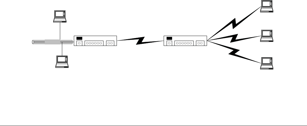
PRELIMINARY
Atheros Communications, Inc. Atheros AP System User’s Guide • 73
COMPANY CONFIDENTIAL Jan 2009
3.4.2 Multiple APs With Different Security Modes
This example shows how a set of VAPs with different security modes can be defined. NOTE THAT THE WEP VAP IS
ATH0. This is required due to hardware limitations.
# export AP_STARTMODE=multi
# export AP_SSID=AP_wep
# export AP_SECMODE=WEP
# export AP_SECFILE=WEP.conf
# export AP_SSID_2=AP_open
# export AP_SECMODE_2=NONE
# export AP_SSID_3=AP_psk
# export AP_SECMODE_3=WPA
# export AP_SECFILE_3=wpa2-psk.conf
# export AP_SSID_4=AP_eap
# export AP_SECMODE_4=WPA
# export AP_SECFILE_4=wpa2EAP.conf
# apup
3.4.3 Changing Parameters in mBSSID Modes
It is highly recommended that the environmental variable method for configuring the AP be used. Since the ATH object
is shared, any configuration change that causes changes in the ATH object will also affect all defined VAPs. Some of
these changes can cause unstable behavior if the VAPs are running while they are made. Therefore, if ANY
configuration change is to be made, ALL VAPs must be brought down using ifconfig, and brought back up after the
configuration changes have been made.
3.5 Wi-Fi Distribution System (WDS)
The WDS system is used to create a network of AP’s that can be used as a single “virtual” AP. This is accomplished by
the 4 address frame format as specified by the 802.11 specification, in conjunction with layer 2 bridging implemented in
the AP. The MAC frames are forwarded to the appropriate AP based on the final destination MAC address provided.
WDS is essentially a tunneling protocol, and is unique to 802.11 implementations.
Several configurations can be implemented, as outlined in the following sections. All rely on a “root” AP device that is
the center of a “star” configuration of nodes.
3.5.1 AP With Single WDS Repeater
This configuration provides a single RF repeater station/AP that is used to bridge between a root AP and remote clients.
The repeater will have two VAPs: one that is a STA that connects to the root AP, and one that provides an Access Point
for the remote stations to associate to. The link between the Repeater and the Root AP uses the WDS mechanism with 4
address frames.
Ethernet
Laptop computer
(STA)
Root AP
Laptop computer
Laptop computer
(STA)
Laptop computer
(STA)
Laptop computer
Repeater
ATH0
ATH1
ATH0
3.5.1.1 Limitations
When running in repeater mode, the following limitations apply:
xVAP configuration after start are subject to the conditions specified in
section 3.4.3 and section 0
xUse the environmental variable method to configure the VAPs.
73
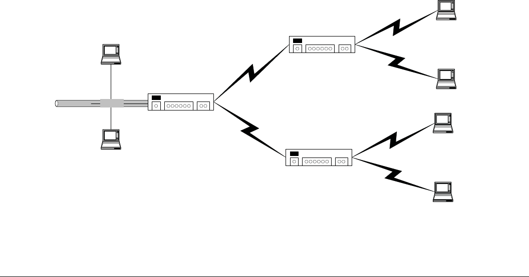
PRELIMINARY
3.5.1.2 Setup
Instructions
This mode requires a different configuration file in the root AP and in the repeater. The root AP is responsible for the
main “distribution” of the data packets. Each repeater will pass packets to its associated STA clients. Note that a station
will associate with the AP with the strongest signal – associating to the Root AP is allowed. Ensure you are using hard
wired connections if you are trying to force a specific configuration.
Also note that the IP addresses of the root AP and the repeater must be different, but on the same subnet. DHCP should
be enabled on only one of the routers (the root AP), or on a separate device attached to the network. Finally, both units
must have the same SSID to form a single BSS. If you want to specify a specific channel or SSID for the setup, ensure
you include all required environmental variable definitions (e.g. AP_SSID, AP_PRIMARY_CH, AP_CHMODE) before
you start apup.
Configuring the Root AP
The following will set up a root AP using the default SSID on channel 6.
# export AP_STARTMODE=rootap
# apup
Configuring the repeater
The following will set up a repeater using the default SSID on channel 6.
# export AP_STARTMODE=repeater
# apup
Ensure both systems are set up prior to starting the APs. The Root AP and the repeater can be started in any order.
Ensure the clients for a system under test associate with the repeater by either using a “hard wired” air interface, ensuring
the repeater signal is greater than the Root AP signal at the clients, or by using a hardware “air” interface.
3.5.2 AP with Multiple Repeaters
This is the extended version of the previous configuration. Multiple repeaters can be associated with a single Root AP,
providing a larger coverage area. This type of configuration is designed to be used in situations where the two repeater
stations do not “see” each other, therefore there is typically no link between the repeaters themselves – all traffic goes
through the Root AP. Testing should be accomplished in the same manner – the two repeaters should not “see” each
other.
Ethernet
Laptop computer
(STA)
Root AP
Laptop computer
Laptop computer
(STA)
Laptop computer
Repeater
Laptop computer
(STA)
Laptop computer
(STA)
Repeater
ATH0
ATH0
ATH0
ATH1
ATH1
74
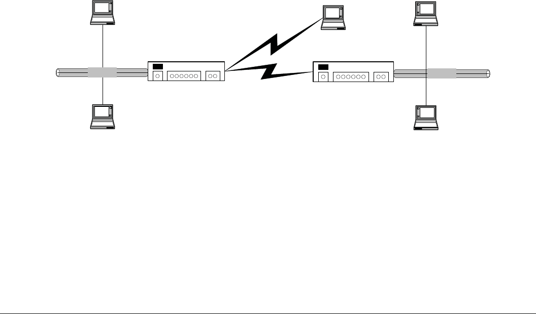
PRELIMINARY
3.5.2.1 Limitations
When running in the multiple repeater mode, the following limitations apply:
xVAP configuration after start is subject to the conditions specified in
section 3.4.3 and section 0.
xUse the environmental variable method to configure the VAPs.
3.5.2.2 Setup Instructions
This configuration is set up in the same manner as the previous configuration. Note that each repeater must have a
unique IP address, on the same subnet. The SSID for both repeaters, as well as the Root AP must be identical to form a
BSS. The root AP controls the security mode, so ensure both repeaters are set up to be consistent with the Root AP.
Ensure that the repeaters have the AP_STARTMODE environmental variable set to “repeater”, as shown in section
3.5.1.2. The root AP is configured with the same setup as in section 3.5.1.2. The AP’s can be started in any order. To
ensure that the repeater stations associate to the root AP (and not each other, since they are using the same SSID), define
the ROOTAP_MAC environmental variable in the form xx:xx:xx:xx:xx:xx. This is required to force association to the
root AP. This is only required in this situation where multiple repeaters have the same SSID, and may accidentally be
closer than the root AP to another repeater AP.
3.5.3 WDS Bridge with single span
This configuration is a wireless bridge between two Ethernet subnets. This configuration uses the WDS feature to
provide the bridging. Client stations can either be attached to one of the two Ethernet subnets, or can associate directly
with the Root AP. The latter case is not typically tested in this configuration, but is not disallowed. This situation is
different from the repeater mode in that the Station node does not also have an AP VAP, so no station can associate with
the station (no Ad-Hoc allowed). This makes either the WDS link, or the Ethernet links the only way traffic enters/exits
the AP.
This solution is typically used in cases where the user wants to join subnets that are located a distance from each other,
or in a home situation where it is preferable not to run wires between rooms. Only one of the servers on this network
should be serving DHCP addresses – typically the Root AP.
Ethernet
Laptop computer
Laptop computer
Ethernet
Root AP
Laptop computer
Laptop computer
WDS STA
Laptop computer
3.5.3.1 Limitations
When running in the WDS Bridge mode, the following limitations apply:
xVAP configuration after start is subject to the conditions specified in
section 3.4.3 and section 0.
xUse the environmental variable method to configure the VAPs.
75
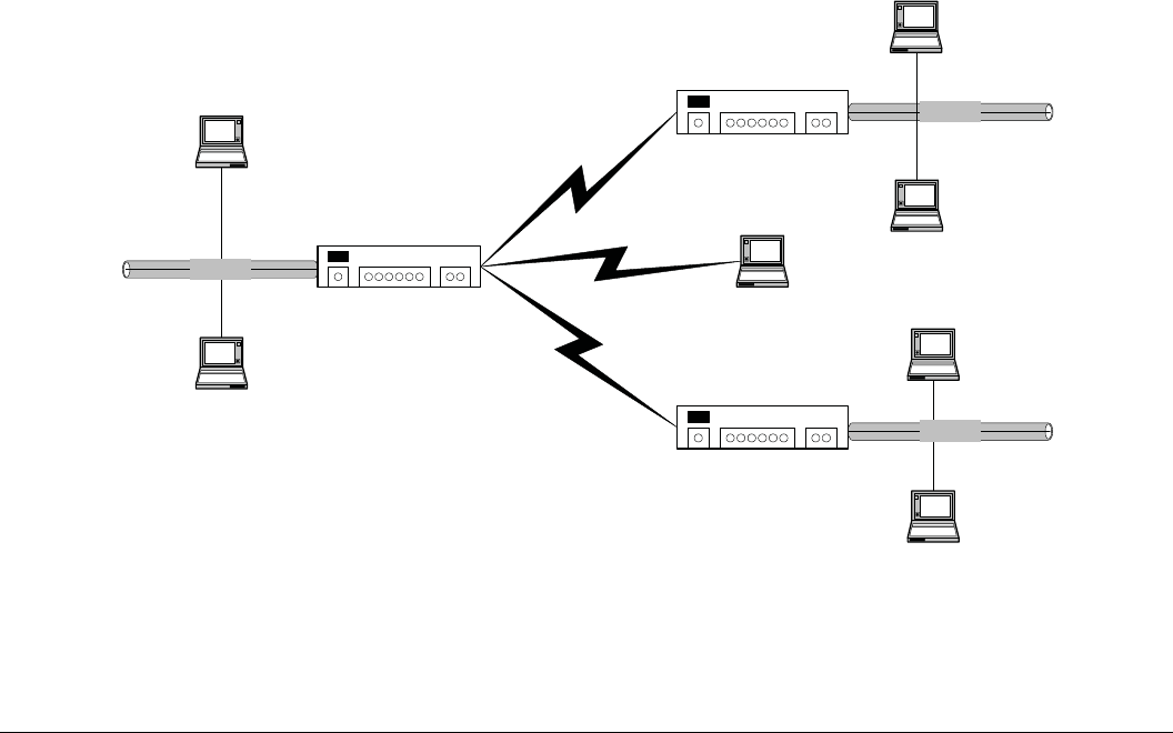
PRELIMINARY
3.5.3.2 Setup
Instructions
To create this configuration, the Root AP and the Client must be configured accordingly. The root AP configuration is
identical to that used in the repeater case. The Client setup however, is set to “client” mode vice “repeater” mode. This
creates only a single station VAP that associates with the Root AP. Again, to setup different channel/SSID
configurations, ensure the proper environmental variables are set.
Configuring the Root AP
The following will set up a root AP using the default SSID on channel 6.
# export AP_STARTMODE=rootap
# apup
Configuring the repeater
The following will set up a client using the default SSID on channel 6, associating with a particular root AP.
# export AP_STARTMODE=client
# export ROOTAP_MAC=00:03:04:32:45:56
# apup
Again, the client AP and the root AP must have the same SSID to form a BSS, but unique IP addresses. Once
configured, the APs can be started in any order. Note that if a client is attached to a remote subnet, and the root AP is the
DHCP server, that the remote clients will not get a DHCP address until the root AP is up, and the client AP is associated
with it.
3.5.4 WDS Bridge with multiple span
As with the repeater case, the multiple-WDS Bridge scenario is an extension of the single bridge scenario. Multiple AP
clients associate with a single root AP, which provides the center of a “star” network topology. In this situation, the
stations are used to link multiple Ethernet subnets into a single large subnet. Again, only a single DHCP server is
allowed in this configuration. The Root AP can have other stations associate with it in the normal manner.
Ethernet
Laptop computer
Laptop computer
WDS STA
Ethernet
Laptop computer
Laptop computer
Ethernet
Root AP
Laptop computer
Laptop computer
WDS STA
Laptop computer
3.5.4.1 Limitations
When running in the WDS Bridge mode, the following limitations apply:
xVAP configuration after start is subject to the conditions specified in 3.4.3
and section 0.0
xUse the environmental variable method to configure the VAPs.
76

PRELIMINARY
3.5.4.2 Setup
Instructions
Setup is identical to the single span case. All clients must have the client configuration in apcfg, each must have an
unique IP address, but all must be configured with the same SSID. The root/clients can be started in any order.
3.6 Dual Concurrent Operations
Dual concurrent operations go hand in hand with multiple VAP operations, because to operate in dual concurrent mode
multiple VAPs must be instantiated. These VAPs can have the same SSID and security configurations, but will have
different MAC addresses. Further, the hardware must support dual concurrent mode in that it has multiple physical WiFi
chipsets implementing individual radio interfaces. The VAPs have to be assigned to a specific interface. The following
example will create an AP operating in the 2.4 GHz band on the wifi0 interface, and an AP operating in the 5.0 GHz
band with the same ESSID on the wifi1 interface:
# export AP_STARTMODE=multi
# export AP_SSID=DualAP
# export IF_NUM=0:RF:11:11G
# export AP_SSID_2=DualAP
# export IF_NUM_2=1:RF:36:11NGHT40PLUS
# apup
77
pg
and an AP operating in the 5.0 GHz
ppg
b
and with the same E
SS
ID on the
w
ifi
1
int
e
rfa
ce:

PRELIMINARY
Appendix A Country Code Definition
The following table identifies the country definition, country string, and country code used to set the country ID for
802.11 and regulatory requirements.
Table 14 Country Code Definition
Country Define Country String Country ID
CTRY_DEBUG "DB" 0
CTRY_DEFAULT "NA" 0
CTRY_ALBANIA "AL" 8
CTRY_ALGERIA "DZ" 12
CTRY_ARGENTINA "AR" 32
CTRY_ARMENIA "AM" 51
CTRY_AUSTRALIA "AU" 36
CTRY_AUSTRALIA2 5000
CTRY_AUSTRIA "AT" 40
CTRY_AZERBAIJAN "AZ" 31
CTRY_BAHRAIN "BH" 48
CTRY_BELARUS "BY" 112
CTRY_BELGIUM "BE" 56
CTRY_BELIZE "BZ" 84
CTRY_BOLIVIA "BO" 68
CTRY_BOSNIA_HERZEGOWINA "BA"
CTRY_BRAZIL “BR” 76
CTRY_BRUNEI_DARUSSALAM "BN" 96
CTRY_BULGARIA "BG" 100
CTRY_CANADA "CA" 124
CTRY_CANADA2 5001
CTRY_CHILE "CL"
CTRY_CHINA "CN" 152
CTRY_COLOMBIA "CO" 170
CTRY_COSTA_RICA "CR" 191
CTRY_CROATIA "HR"
CTRY_CYPRUS "CY" 196
CTRY_CZECH "CZ" 203
CTRY_DENMARK "DK" 208
CTRY_DOMINICAN_REPUBLIC "DO" 214
CTRY_ECUADOR "EC" 218
CTRY_EGYPT "EG" 818
CTRY_EL_SALVADOR "SV" 222
78

PRELIMINARY
CTRY_ESTONIA "EE" 233
CTRY_FAEROE_ISLANDS 234
CTRY_FINLAND "FI" 246
CTRY_FRANCE "FR" 250
CTRY_FRANCE2 "F2" 255
CTRY_GEORGIA "GE" 268
CTRY_GERMANY "DE" 276
CTRY_GREECE "GR" 300
CTRY_GUATEMALA "GT" 320
CTRY_HONDURAS "HN" 340
CTRY_HONG_KONG "HK" 344
CTRY_HUNGARY "HU" 348
CTRY_ICELAND "IS" 352
CTRY_INDIA "IN" 356
CTRY_INDONESIA "ID" 360
CTRY_IRAN "IR" 364
CTRY_IRAQ 368
CTRY_IRELAND "IE" 372
CTRY_ISRAEL "IL" 376
CTRY_ITALY "IT" 380
CTRY_JAMAICA 388
CTRY_JAPAN "JP" 392
CTRY_JAPAN1 "J1" 393
CTRY_JAPAN2 "J2" 394
CTRY_JAPAN3 "J3" 395
CTRY_JAPAN4 "J4" 396
CTRY_JAPAN5 "J5" 397
CTRY_JAPAN6 "J6" 399
CTRY_JAPAN7 "JP" 4007
CTRY_JAPAN8 "JP" 4008
CTRY_JAPAN9 "JP" 4009
CTRY_JAPAN10 "JP" 4010
CTRY_JAPAN11 "JP" 4011
CTRY_JAPAN12 "JP" 4012
CTRY_JAPAN13 "JP" 4013
CTRY_JAPAN14 "JP" 4014
CTRY_JAPAN15 "JP" 4015
CTRY_JAPAN16 "JP" 4016
79

PRELIMINARY
CTRY_JAPAN17 "JP" 4017
CTRY_JAPAN18 "JP" 4018
CTRY_JAPAN19 "JP" 4019
CTRY_JAPAN20 "JP" 4020
CTRY_JAPAN21 "JP" 4021
CTRY_JAPAN22 "JP" 4022
CTRY_JAPAN23 "JP" 4023
CTRY_JAPAN24 "JP" 4024
CTRY_JAPAN25 4025
CTRY_JAPAN26 4026
CTRY_JAPAN27 4027
CTRY_JAPAN28 4028
CTRY_JAPAN29 4029
CTRY_JAPAN30 4030
CTRY_JAPAN31 4031
CTRY_JAPAN32 4032
CTRY_JAPAN33 4033
CTRY_JAPAN34 4034
CTRY_JAPAN35 4035
CTRY_JAPAN36 4036
CTRY_JAPAN37 4037
CTRY_JAPAN38 4038
CTRY_JAPAN39 4039
CTRY_JAPAN40 4040
CTRY_JAPAN41 4041
CTRY_JAPAN42 4042
CTRY_JAPAN43 4043
CTRY_JAPAN44 4044
CTRY_JAPAN45 4045
CTRY_JAPAN46 4046
CTRY_JAPAN47 4047
CTRY_JAPAN48 4048
CTRY_JAPAN49 4049
CTRY_JAPAN50 4050
CTRY_JAPAN51 4051
CTRY_JAPAN52 4052
CTRY_JAPAN53 4053
CTRY_JAPAN54 4054
80

PRELIMINARY
CTRY_JAPAN55 4055
CTRY_JAPAN56 4056
CTRY_JORDAN "JO" 400
CTRY_KAZAKHSTAN "KZ" 398
CTRY_KENYA "KE" 404
CTRY_KOREA_NORTH "KP" 408
CTRY_KOREA_ROC "KR" 410
CTRY_KOREA_ROC2 "K2" 411
CTRY_KOREA_ROC3 412
CTRY_KUWAIT "KW" 414
CTRY_LATVIA "LV" 428
CTRY_LEBANON "LB" 422
CTRY_LIBYA 434
CTRY_LIECHTENSTEIN "LI" 438
CTRY_LITHUANIA "LT" 440
CTRY_LUXEMBOURG "LU" 442
CTRY_MACAU "MO" 446
CTRY_MACEDONIA "MK" 807
CTRY_MALAYSIA "MY" 458
CTRY_MALTA 470
CTRY_MEXICO "MX" 484
CTRY_MONACO "MC" 492
CTRY_MOROCCO "MA" 504
CTRY_NETHERLANDS "NL" 528
CTRY_NEW_ZEALAND "NZ" 554
CTRY_NICARAGUA 558
CTRY_NORWAY "NO" 578
CTRY_OMAN "OM" 512
CTRY_PAKISTAN "PK" 586
CTRY_PANAMA "PA" 591
CTRY_PARAGUAY 600
CTRY_PERU "PE" 604
CTRY_PHILIPPINES "PH" 608
CTRY_POLAND "PL" 616
CTRY_PORTUGAL "PT" 620
CTRY_PUERTO_RICO "PR" 630
CTRY_QATAR "QA" 634
CTRY_ROMANIA "RO" 642
81

PRELIMINARY
CTRY_RUSSIA "RU" 643
CTRY_SAUDI_ARABIA "SA" 682
CTRY_SERBIA_MONTENEGRO 891
CTRY_SINGAPORE "SG" 702
CTRY_SLOVAKIA "SK" 703
CTRY_SLOVENIA "SI" 705
CTRY_SOUTH_AFRICA "ZA" 710
CTRY_SPAIN "ES" 724
CTRY_SRI_LANKA "LK"
CTRY_SWEDEN "SE" 752
CTRY_SWITZERLAND "CH" 756
CTRY_SYRIA "SY" 760
CTRY_TAIWAN "TW" 158
CTRY_THAILAND "TH" 764
CTRY_TRINIDAD_Y_TOBAGO "TT" 780
CTRY_TUNISIA "TN" 788
CTRY_TURKEY "TR" 792
CTRY_UAE "AE" 784
CTRY_UKRAINE "UA" 804
CTRY_UNITED_KINGDOM "GB" 826
CTRY_UNITED_STATES "US" 840
CTRY_UNITED_STATES_FCC49 "US" 842
CTRY_URUGUAY "UY" 858
CTRY_UZBEKISTAN "UZ" 860
CTRY_VENEZUELA "VE" 862
CTRY_VIET_NAM "VN" 704
CTRY_YEMEN "YE" 887
CTRY_ZIMBABWE "ZW" 716
82
This device is intended for use under the following conditions:
1. The transmitter module may not be co-located with any other transmitter or antenna.
2. The module is approved using the FCC “unlicensed modular transmitter approval” method.
As long as these two conditions are met, further transmitter testing will not be required. However,
the OEM integrator is still responsible for testing their end product for any additional compliance
measures necessitated by the installation of this module (i.e. digital device emissions, PC
peripheral requirements, etc.).
Note: In the event that these conditions cannot be met (i.e. co-location with another transmitter),
then the FCC authorization is no longer valid and the corresponding FCC ID may not be used on
the final product.
The end user should NOT be provided with any instructions on how to remove or install the
modular. The following sentence has to be displayed on the outside of device in which the
transmitter module is installed "Contains FCC ID: TFJAG1311"