Uniform MFC242 Payment Reader User Manual manual
Uniform Industrial Corp. Payment Reader manual
UserManual.wiki
>
Uniform
>
MFC242 User Manual
manual
Navigation menu
Upload a User Manual
Namespaces
Wiki Guide
HTML
PDF
Info
Views
User Manual
Discussion / Help
Navigation
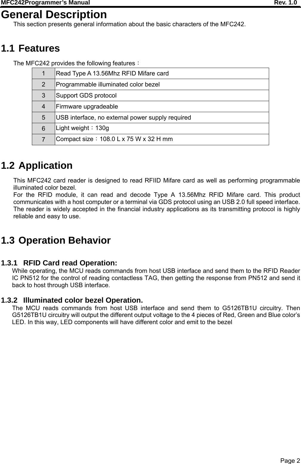
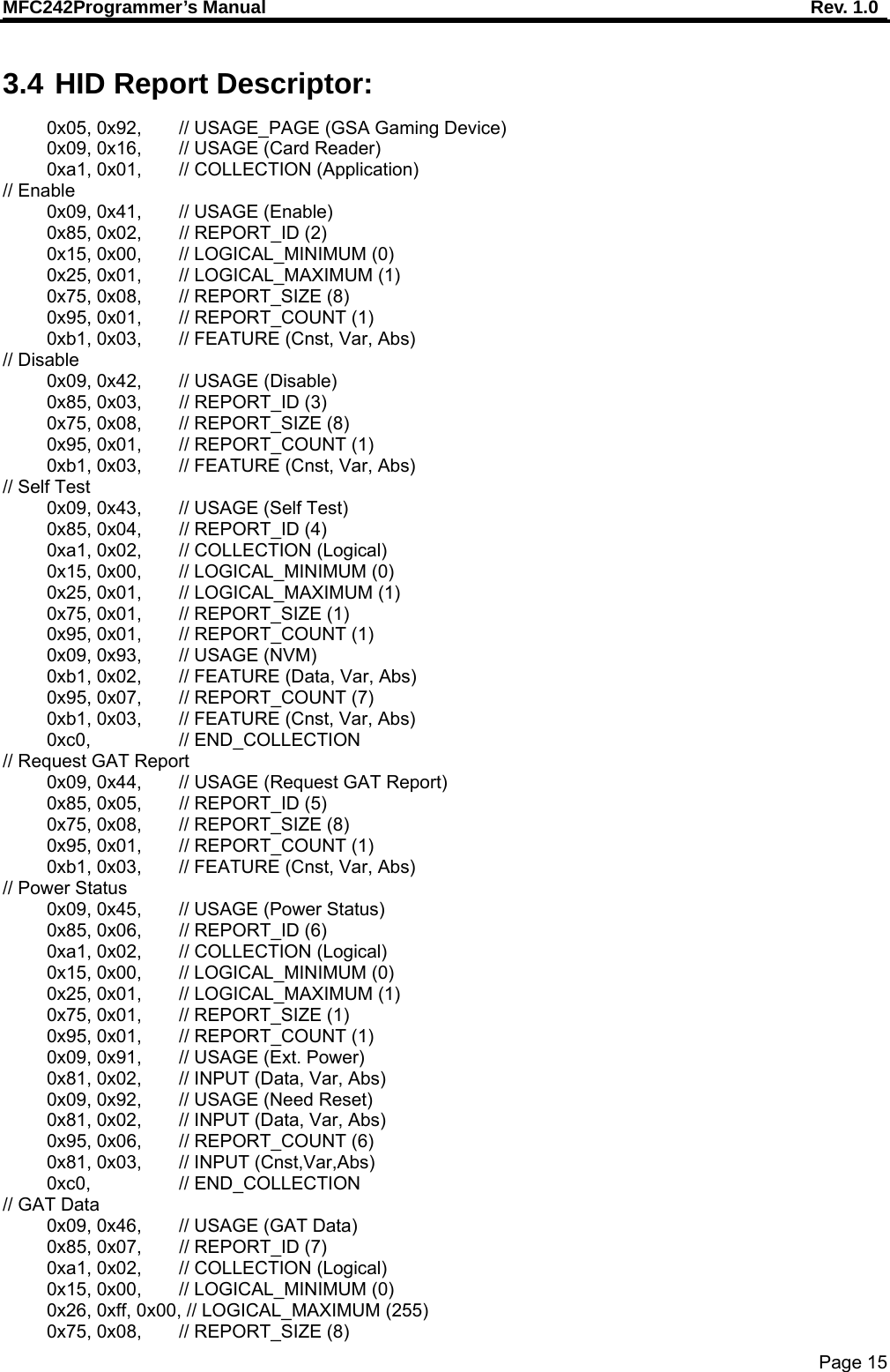
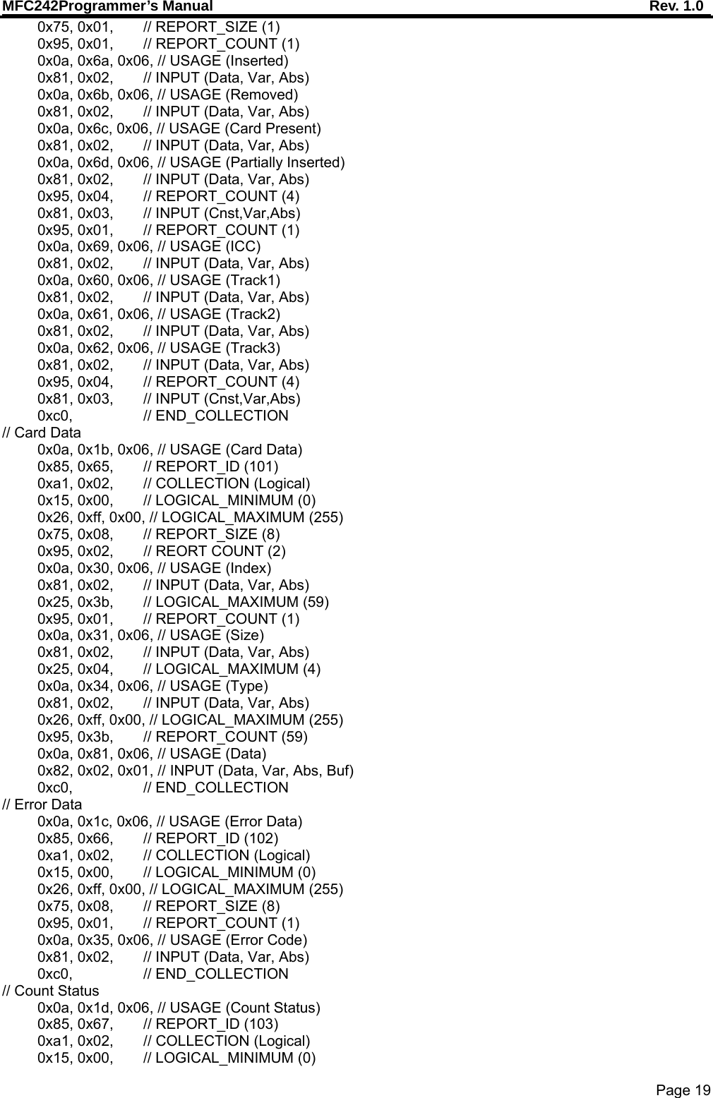
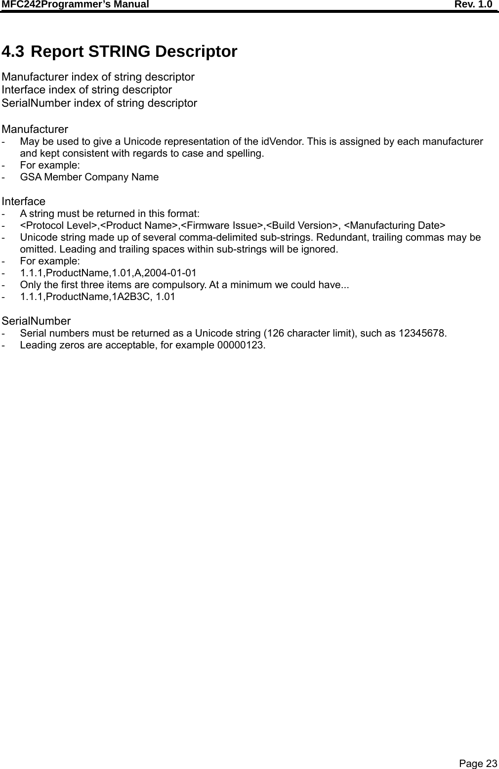
![MFC242Programmer’s Manual Rev. 1.0 Page 7 2.6.1 Boot Loader Block The first 12Kbyte of memory is factory programmed with a boot loader. The boot loader is designed to update application program through USB communication per HID V1.12 with a predefined communication protocol. Please refer to the appendix section for more information. Command and Response Format Command Format: <Header> <LEN_1><Command_1><LEN_2><Command_2><DATA><ADDLRC><XORLRC> Response Format: < Header><Length><DATA> Note: The <Header> of Command/Response must be ‘C2’ (Hex). The <LEN 1> field indicates the length from <Command_1> to <XORLRC>, it is two bytes. The <LEN 2> field indicates the length from < Command_2> to < ADDLRC>, it is two bytes. The <Data> fields are command or response data. See following section “Command and Response Code” for details. Response Format: < Header>< Length><DATA> Command_1 Command_2 Description 0x09 0x042 0x4C Enter to Boot Loader Block 0x21 0x7E CHECK Uniform produce 0x057 0x46 Program Flash address data length (max size 1024) 0x042 0x4E Get previous command 0x045 0x42 0x4C Get Boot Loader Version 0x45 0x4D Erase Flash 0x39 Get Application Program Version 0x7F Warm Reset 0x09 - Enter to Boot Loader Block Command Length: 3 bytes Response Data: = 06h, if success. Length is 1 byte. = 15h, if failure. Length is 1 byte. 0x21 – 0x7E- CHECK UNIFORM Produce Command Length: 2 bytes Response Data: = UNIFORM XOR some data, if success. Length is 8 bytes. = 15h, if failure. Length is 1 byte. 0x057 0x46 - Program Flash address data length (max size 1024) Command Length: 3 bytes Response Data: = 06h, if success. Length is 1 byte. = 15h, if failure. Length is 1 byte. 0x042 0x4E get previous command Command Length: 3 bytes Response Data: = ”OK”, if success. Length is 2 bytes. = 15h, if failure. Length is 1 byte. 0x045 0x42 0x4C Get Boot Loader Version Command Length: 4 bytes Response Data: = [Version], if success. Length is 8 bytes. = 15h, if failure. Length is 1 byte. 0x45 0x4d Erase Flash Command Length: 3 bytes Response Data: = ”OK”, if success. Length is 2 bytes. = 15h, if failure. Length is 1 byte. 0x39 - Get Application Program Version](https://usermanual.wiki/Uniform/MFC242/User-Guide-2364890-Page-8.png)
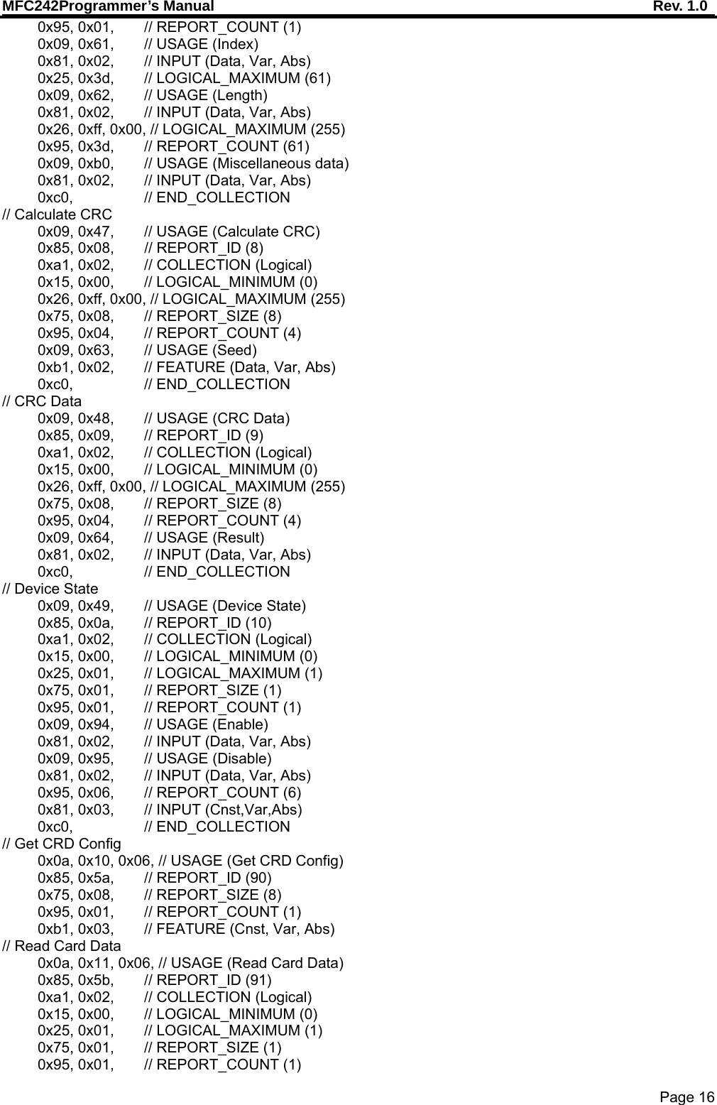
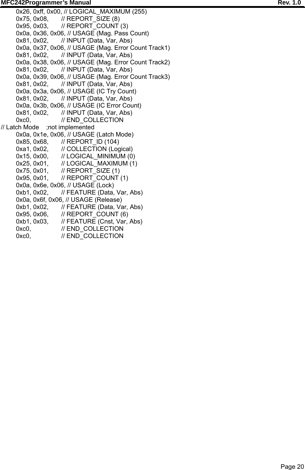
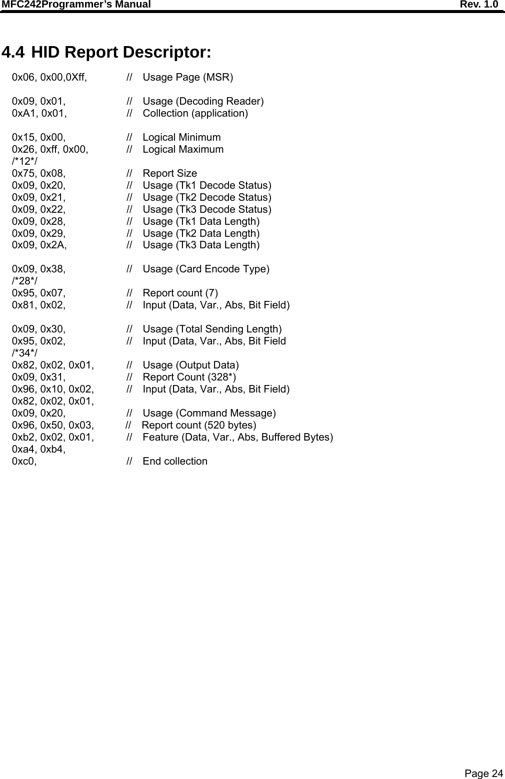
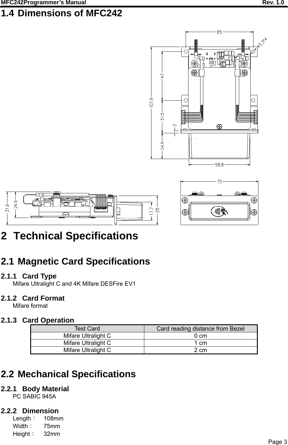
![MFC242Programmer’s Manual Rev. 1.0 Page 8 Command Length: 1 byte Response Data: = [Version], if success. Length is 8 bytes. = 15h, if failure. Length is 1 byte. 0x7F - Warm Reset Command Length: 1 byte Response Data: = 06h, if success. Length is 1 byte. Warm Reset will perform. = 15h, if failure. Length is 1 byte. Warm Reset not allowed 2.6.2 Application Program Block The 46Kbyte from 0x3000 to 0xE7FF is Application Program. It is the main application code held in the microprocessor. The microprocessor will execute it to perform related operation per USB HID V1.12. Please refer to the appendix section for more information. HID COMMAD Response format Byte 0 Page report ID Byte 1 Data or length or states Byte 2 Data or length Commutation Report ID Usage ID Name Operation When Device Enabled Operation When Device Disabled 0x02 0x41 Enable Yes Yes 0x03 0x42 Disable Yes Yes 0x04 0x43 Self Test No Yes 0x05 0x44 (Not implemented) Request GAT Report No Yes 0x08 0x47 Calculate CRC No Yes 0x5A 0x0610 Get CRD Configuration No Yes 0x5B 0x0611 Read Card Data Yes No 0x5C 0x0612 (Not implemented) Get ATR Yes No 0x5D 0x0613 (Not implemented) Transfer to ICC Yes No 0x5E 0x0614 (Not implemented) Release Latch Yes Yes 0x5F 0x0615 Light Control Yes Yes 0x60 0x0616 Clear Buffer Yes No 0x61 0x0617 (Not implemented) Get Count Status Yes Yes 0x68 0x061E (Not implemented) Latch Mode Yes Yes 0x7F User set feature Dump Memory Yes Yes](https://usermanual.wiki/Uniform/MFC242/User-Guide-2364890-Page-9.png)
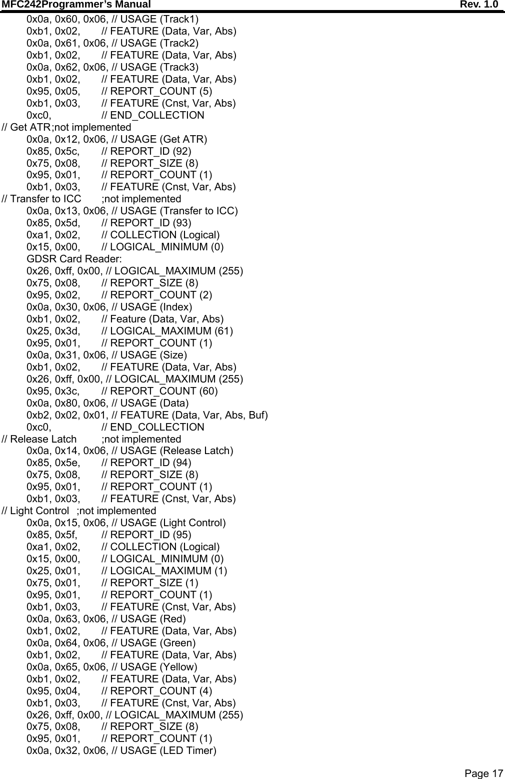
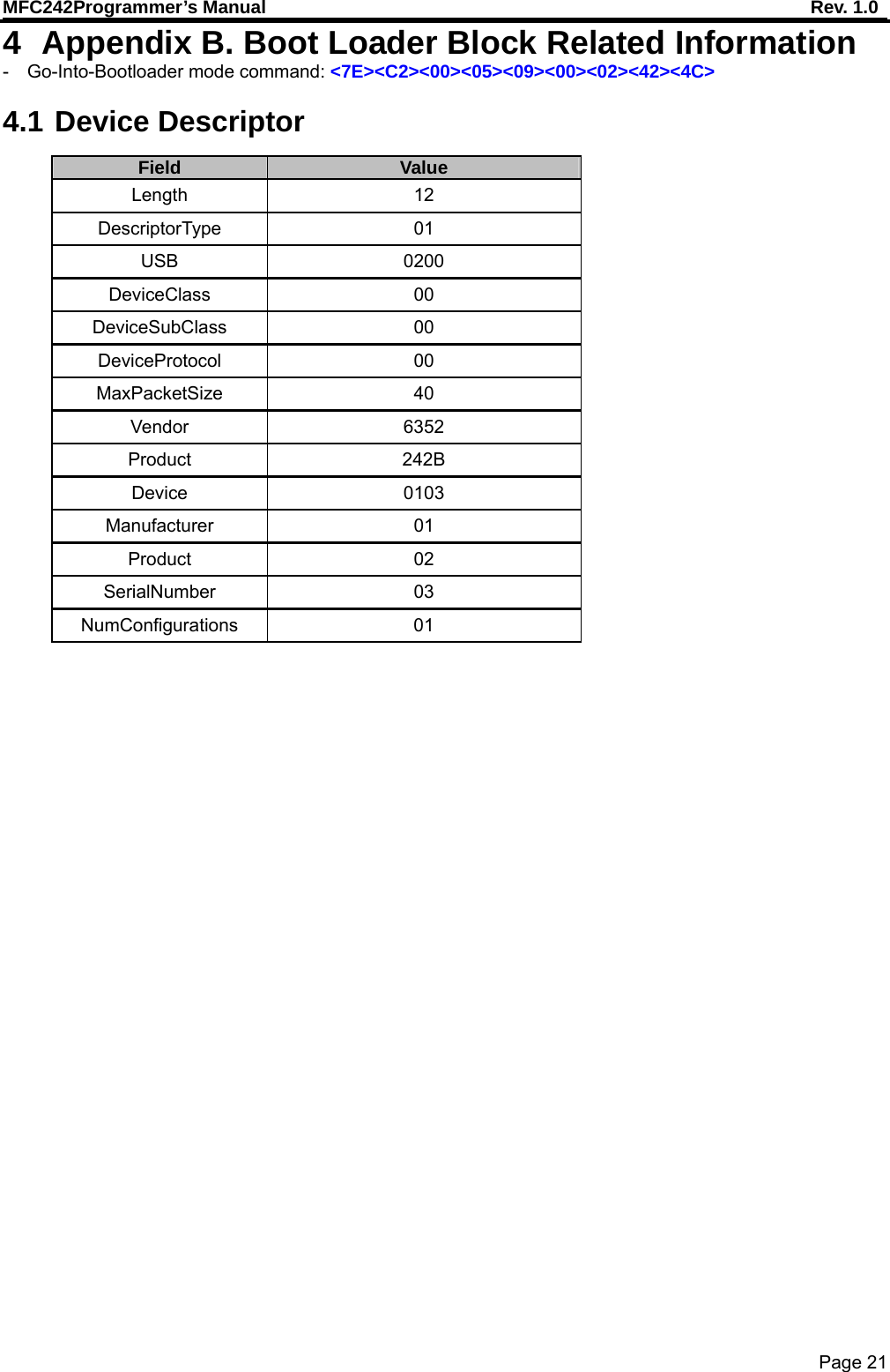
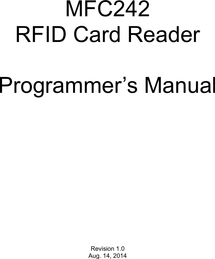
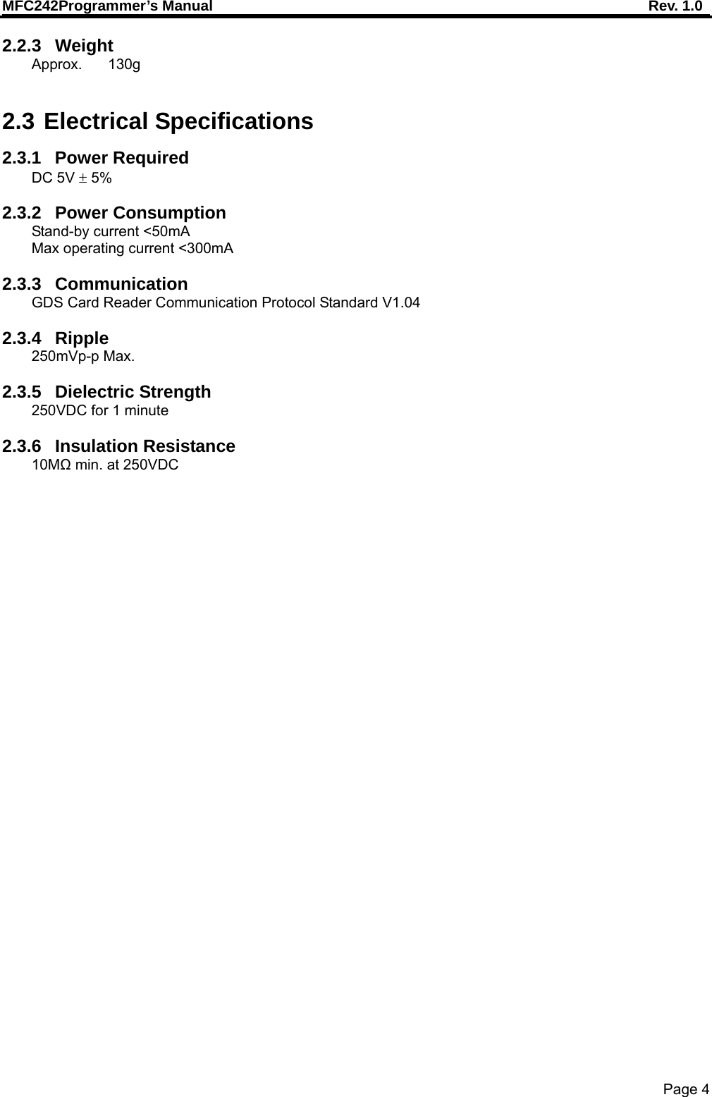
![MFC242Programmer’s Manual Rev. 1.0 Page 9 0x5F 0x0615 Light Control This command is used to control the LEDs of a reader. Bit 7 6 5 4 3 2 1 0 Byte 0 0x5F Byte 1 Pattern 1Red LSB Byte 2 Pattern 1Red MSB Byte 3 Pattern 1Green LSB Byte 4 Pattern 1Green MSB Byte 5 Pattern 1Blue LSB Byte 6 Pattern 1Blue MSB Byte 7 Pattern 2 Red LSB Byte 8 Pattern 2 Red MSB Byte 9 Pattern 2 Green LSB Byte 10 Pattern 2 Green MSB Byte 11 Pattern 2 Blue LSB Byte 12 Pattern 2 Blue MSB Byte 13 Flashing Frequency 0x7F Dump Memory This command is used to read the binary code of Boot Loader or Application Program. The parameter [EEPROM Address] must be in the range 0x0000 to 0xE7FF. Command: 7F + EEPROM Address [2 bytes] + Dump Length [2 bytes, max 63] Response: 7F + Dump content [max 63] EVENT SUPPORT Report ID Usage ID Event Data N/A USB Defined Connection No N/A USB Defined Disconnection No 0x06 0x45 (Not implemented) Power Status Yes 0x07 0x46 (Not implemented) GAT Data Yes 0x09 0x48 CRC Data Yes 0x0A 0x49 (Not implemented) Device State Yes 0x62 0x0618 (Not implemented) Failure Status Yes 0x63 0x0619 CRD Configuration Data Yes 0x64 0x061A Card Status Yes 0x65 0x061B Card Data Yes 0x66 0x061C (Not implemented) Error Data Yes 0x67 0x061D (Not implemented) Count Status Yes - N/A USB Defined Connection - N/A USB Defined Disconnection - 0x06 0x45 Power Status - 0x07 0x46 GAT Data](https://usermanual.wiki/Uniform/MFC242/User-Guide-2364890-Page-10.png)
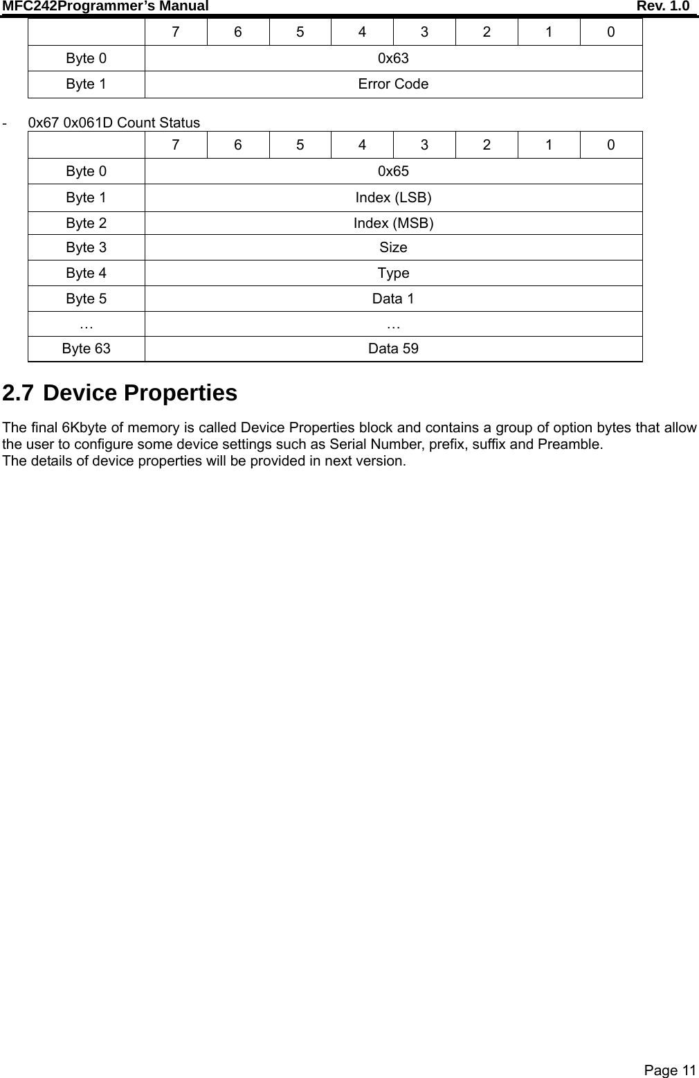
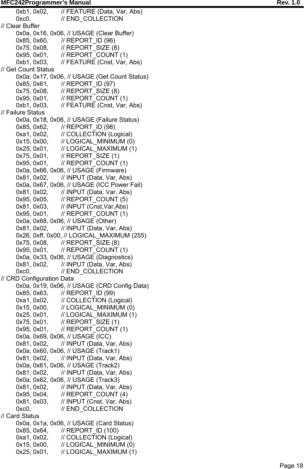
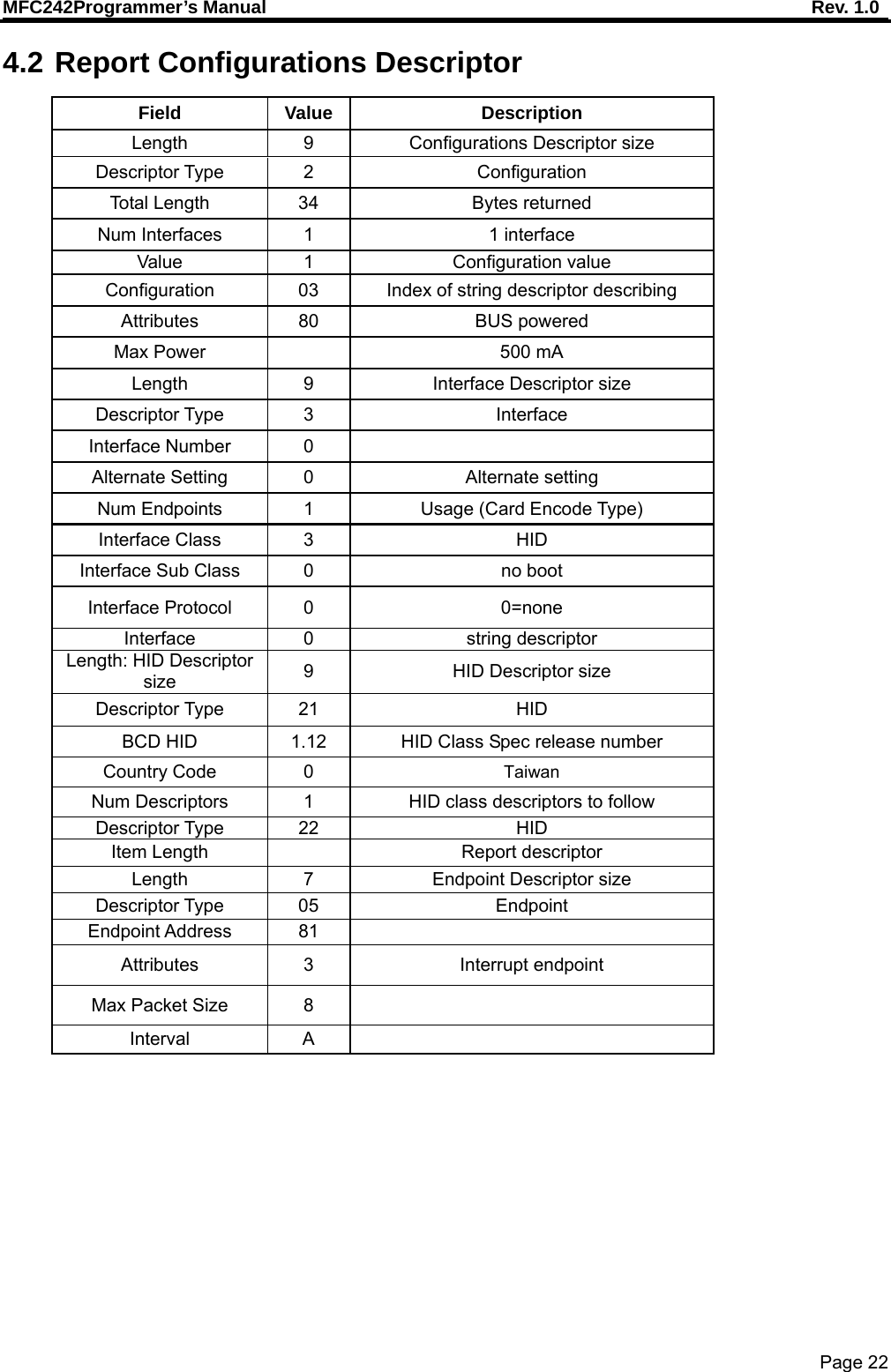
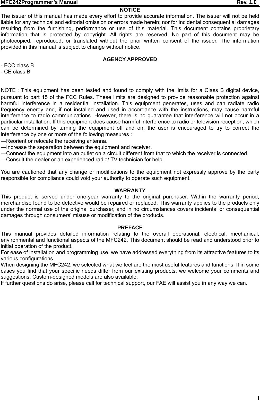
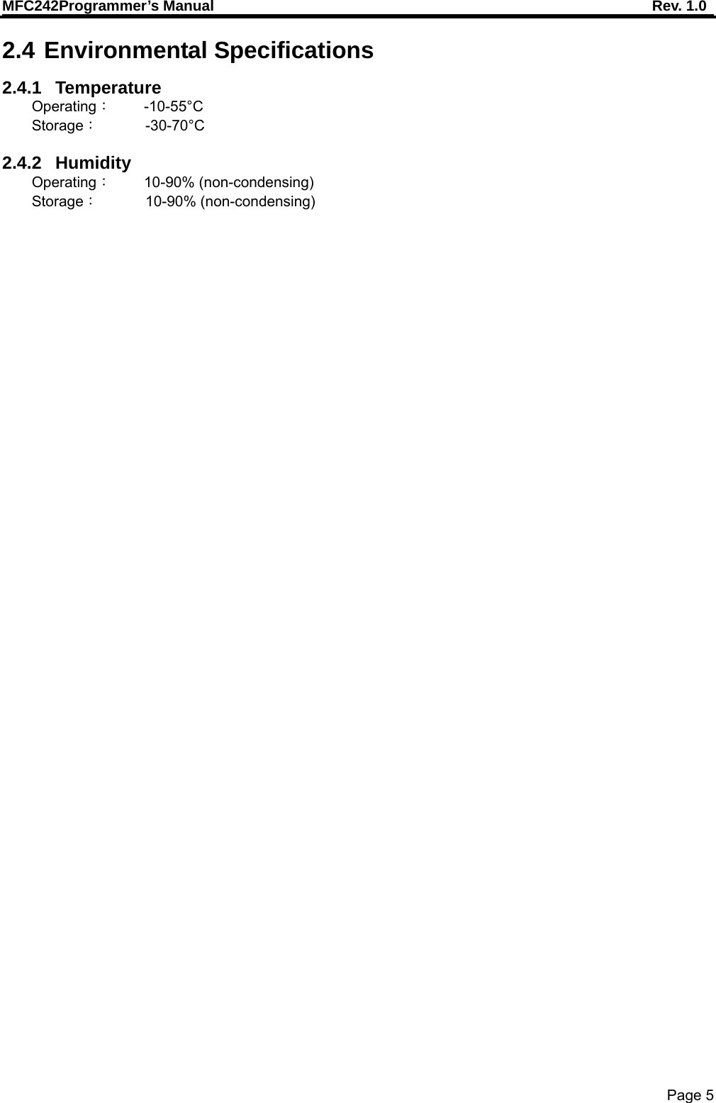
![MFC242Programmer’s Manual Rev. 1.0 Page 10 TX:<none> RX:[ Index ] [ Size ] [ Byte 1 ] … [ Byte 61 ] - 0x09 0x48 CRC Data Calculate CRC TX:[ Seed 0 - LSB ] [ Seed 1 ] [ Seed 2 ] [ Seed 3 - MSB ] CRC Data RX:[ Result 0 - LSB ] [ Result 1 ] [ Result 2 ] [ Result 3 - MSB ] - 0x0A 0x49 Device State 7 6 5 4 3 2 1 0 Byte 0 0x0A Byte 1 Disable Enable - 0x62 0x0618 Failure Status 7 6 5 4 3 2 1 0 Byte 0 0x062 Byte 1 ICC Power Fail Firmware FailByte 2 Diagnostics - 0x63 0x0619 CRD Configuration 7 6 5 4 3 2 1 0 Byte 0 0x63 Byte 1 Track3 Track2 Track1 ICC - 0x64 0x061A Card Status 7 6 5 4 3 2 1 0 Byte 0 0x64 Byte 1 PartiallyInsertedCard Present Removed InsertedByte 2 Track3 Track2 Track1 ICC - 0x65 0x061B Card Data 7 6 5 4 3 2 1 0 Byte 0 0x65 Byte 1 Index (LSB) Byte 2 Index (MSB) Byte 3 Size Byte 4 Type Byte 5 Data 1 … … Byte 63 Data 59 - 0x66 0x061C Error Data](https://usermanual.wiki/Uniform/MFC242/User-Guide-2364890-Page-11.png)