Uniform MFC242 Payment Reader User Manual manual
Uniform Industrial Corp. Payment Reader manual
Uniform >
manual
MFC242
RFID Card Reader
Programmer’s Manual
Revision 1.0
Aug. 14, 2014

MFC242Programmer’s Manual Rev. 1.0
I
NOTICE
The issuer of this manual has made every effort to provide accurate information. The issuer will not be held
liable for any technical and editorial omission or errors made herein; nor for incidental consequential damages
resulting from the furnishing, performance or use of this material. This document contains proprietary
information that is protected by copyright. All rights are reserved. No part of this document may be
photocopied, reproduced, or translated without the prior written consent of the issuer. The information
provided in this manual is subject to change without notice.
AGENCY APPROVED
- FCC class B
- CE class B
NOTE:This equipment has been tested and found to comply with the limits for a Class B digital device,
pursuant to part 15 of the FCC Rules. These limits are designed to provide reasonable protection against
harmful interference in a residential installation. This equipment generates, uses and can radiate radio
frequency energy and, if not installed and used in accordance with the instructions, may cause harmful
interference to radio communications. However, there is no guarantee that interference will not occur in a
particular installation. If this equipment does cause harmful interference to radio or television reception, which
can be determined by turning the equipment off and on, the user is encouraged to try to correct the
interference by one or more of the following measures:
—Reorient or relocate the receiving antenna.
—Increase the separation between the equipment and receiver.
—Connect the equipment into an outlet on a circuit different from that to which the receiver is connected.
—Consult the dealer or an experienced radio/ TV technician for help.
You are cautioned that any change or modifications to the equipment not expressly approve by the party
responsible for compliance could void your authority to operate such equipment.
WARRANTY
This product is served under one-year warranty to the original purchaser. Within the warranty period,
merchandise found to be defective would be repaired or replaced. This warranty applies to the products only
under the normal use of the original purchaser, and in no circumstances covers incidental or consequential
damages through consumers’ misuse or modification of the products.
PREFACE
This manual provides detailed information relating to the overall operational, electrical, mechanical,
environmental and functional aspects of the MFC242. This document should be read and understood prior to
initial operation of the product.
For ease of installation and programming use, we have addressed everything from its attractive features to its
various configurations.
When designing the MFC242, we selected what we feel are the most useful features and functions. If in some
cases you find that your specific needs differ from our existing products, we welcome your comments and
suggestions. Custom-designed models are also available.
If further questions do arise, please call for technical support, our FAE will assist you in any way we can.

MFC242Programmer’s Manual Rev. 1.0
Page 2
General Description
This section presents general information about the basic characters of the MFC242.
1.1 Features
The MFC242 provides the following features:
1 Read Type A 13.56Mhz RFID Mifare card
2 Programmable illuminated color bezel
3 Support GDS protocol
4 Firmware upgradeable
5 USB interface, no external power supply required
6 Light weight:130g
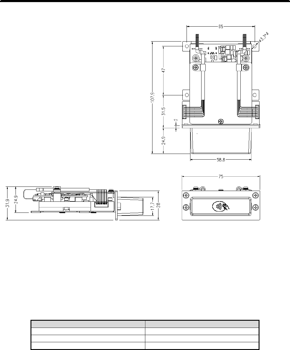
7 Compact size:108.0 L x 75 W x 32 H mm
1.2 Application
This MFC242 card reader is designed to read RFIID Mifare card as well as performing programmable
illuminated color bezel.
For the RFID module, it can read and decode Type A 13.56Mhz RFID Mifare card. This product
communicates with a host computer or a terminal via GDS protocol using an USB 2.0 full speed interface.
The reader is widely accepted in the financial industry applications as its transmitting protocol is highly
reliable and easy to use.
1.3 Operation Behavior
1.3.1 RFID Card read Operation:
While operating, the MCU reads commands from host USB interface and send them to the RFID Reader
IC PN512 for the control of reading contactless TAG, then getting the response from PN512 and send it
back to host through USB interface.
1.3.2 Illuminated color bezel Operation.
The MCU reads commands from host USB interface and send them to G5126TB1U circuitry. Then
G5126TB1U circuitry will output the different output voltage to the 4 pieces of Red, Green and Blue color’s
LED. In this way, LED components will have different color and emit to the bezel
MFC242Programmer’s Manual Rev. 1.0
Page 3
1.4 Dimensions of MFC242
2 Technical Specifications
2.1 Magnetic Card Specifications
2.1.1 Card Type
Mifare Ultralight C and 4K Mifare DESFire EV1
2.1.2 Card Format
Mifare format
2.1.3 Card Operation
Test C ar d Card reading distance from Bezel
Mifare Ultralight C 0 cm
Mifare Ultralight C 1 cm
Mifare Ultralight C 2 cm
2.2 Mechanical Specifications
2.2.1 Body Material
PC SABIC 945A
2.2.2 Dimension
Length: 108mm
Width: 75mm
Height: 32mm

MFC242Programmer’s Manual Rev. 1.0
Page 4
2.2.3 Weight
Approx. 130g
2.3 Electrical Specifications
2.3.1 Power Required
DC 5V 5%
2.3.2 Power Consumption
Stand-by current <50mA
Max operating current <300mA
2.3.3 Communication
GDS Card Reader Communication Protocol Standard V1.04
2.3.4 Ripple
250mVp-p Max.
2.3.5 Dielectric Strength
250VDC for 1 minute
2.3.6 Insulation Resistance
10MΩ min. at 250VDC

MFC242Programmer’s Manual Rev. 1.0
Page 5
2.4 Environmental Specifications
2.4.1 Temperature
Operating: -10-55°C
Storage: -30-70°C
2.4.2 Humidity
Operating: 10-90% (non-condensing)
Storage: 10-90% (non-condensing)
MFC242Programmer’s Manual Rev. 1.0
Page 6
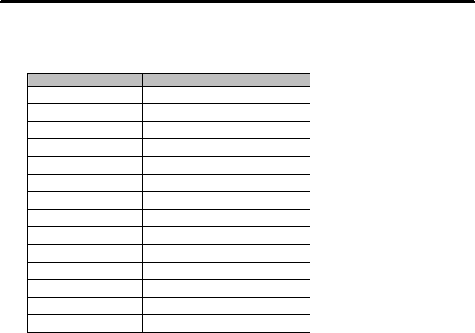
2.5 Pin Assignment
PINNO.DESCRIPTION
1Power
2Data‐
3Data+
4NC
5Ground
2.6 Software Specification
GDS® Card Reader: Communication Protocol v1.0.4
Universal Serial Bus (USB) Specification, v2.0
Device Class Definition for USB HID, v1.12
USB Engineering Change Notice – UNICODE UTF-16LE for String Descriptors
RFC 2781 (Unicode standard version 3.0) new REV 5.2
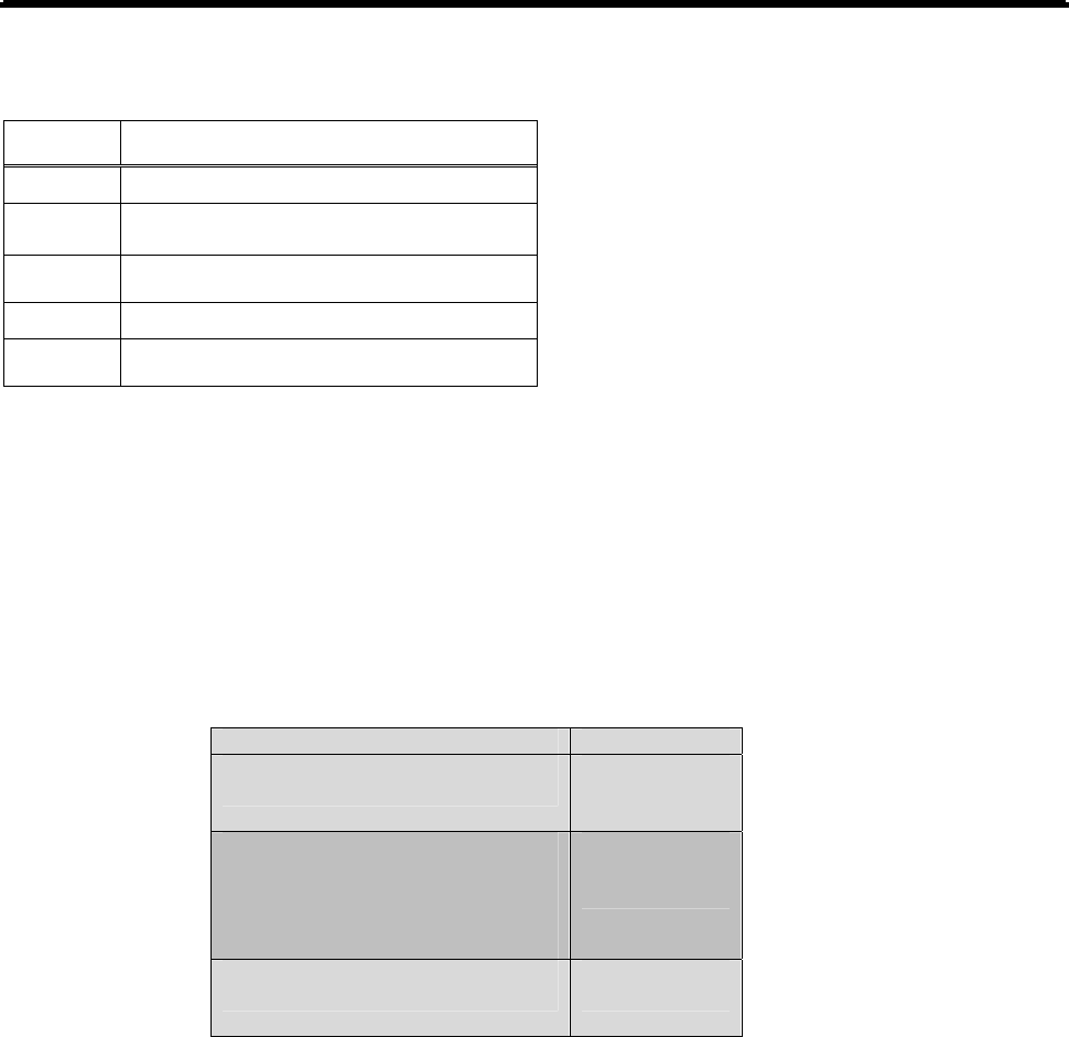
System Memory is divided into three parts:
Base addresses Block Size
0xFFFF
0xE800
Device Properties Block
6K Bytes
0xE7FF
0x3000
Application Program Block
46K Bytes
0x2FFF
0x0000
Boot Loader Block
12K Bytes

MFC242Programmer’s Manual Rev. 1.0
Page 7
2.6.1 Boot Loader Block
The first 12Kbyte of memory is factory programmed with a boot loader. The boot loader is designed to update
application program through USB communication per HID V1.12 with a predefined communication protocol.
Please refer to the appendix section for more information.
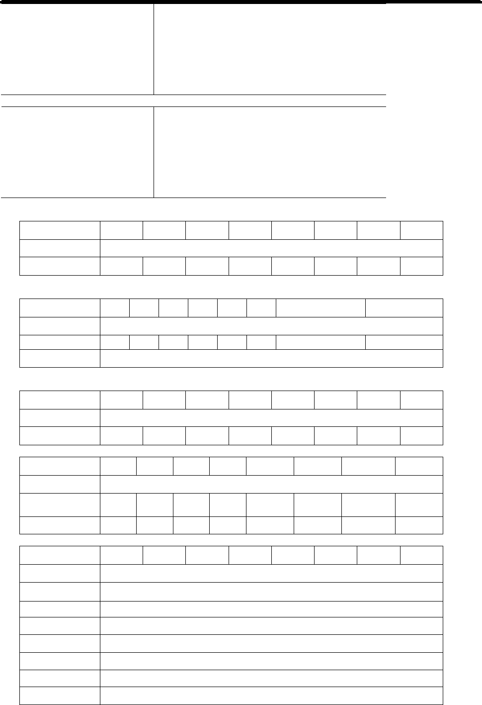
Command and Response Format
Command Format:
<Header> <LEN_1><Command_1><LEN_2><Command_2><DATA><ADDLRC><XORLRC>
Response Format:
< Header><Length><DATA>
Note:
The <Header> of Command/Response must be ‘C2’ (Hex).
The <LEN 1> field indicates the length from <Command_1> to <XORLRC>, it is two bytes.
The <LEN 2> field indicates the length from < Command_2> to < ADDLRC>, it is two bytes.
The <Data> fields are command or response data. See following section “Command and Response
Code” for details.
Response Format:
< Header>< Length><DATA>
Command_1 Command_2 Description
0x09 0x042 0x4C Enter to Boot Loader Block
0x21 0x7E CHECK Uniform produce
0x057 0x46 Program Flash address data length (max size 1024)
0x042 0x4E Get previous command
0x045 0x42 0x4C Get Boot Loader Version
0x45 0x4D Erase Flash
0x39 Get Application Program Version
0x7F Warm Reset
0x09 - Enter to Boot Loader Block
Command Length: 3 bytes
Response Data: = 06h, if success. Length is 1 byte.
= 15h, if failure. Length is 1 byte.
0x21 –
0x7E- CHECK UNIFORM Produce
Command Length: 2 bytes
Response Data: = UNIFORM XOR some data,
if success. Length is 8 bytes.
= 15h, if failure. Length is 1 byte.
0x057 0x46 - Program Flash address data length (max size 1024)
Command Length: 3 bytes
Response Data: = 06h, if success. Length is 1 byte.
= 15h, if failure. Length is 1 byte.
0x042 0x4E get previous command
Command Length: 3 bytes
Response Data: = ”OK”, if success. Length is 2 bytes.
= 15h, if failure. Length is 1 byte.
0x045 0x42 0x4C Get Boot Loader Version
Command Length: 4 bytes
Response Data: = [Version], if success. Length is 8 bytes.
= 15h, if failure. Length is 1 byte.
0x45 0x4d Erase Flash
Command Length: 3 bytes
Response Data: = ”OK”, if success. Length is 2 bytes.
= 15h, if failure. Length is 1 byte.
0x39 - Get Application Program Version

MFC242Programmer’s Manual Rev. 1.0
Page 8
Command Length: 1 byte
Response Data: = [Version], if success. Length is 8 bytes.
= 15h, if failure. Length is 1 byte.
0x7F - Warm Reset
Command Length: 1 byte
Response Data: = 06h, if success. Length is 1 byte. Warm Reset will perform.
= 15h, if failure. Length is 1 byte. Warm Reset not allowed
2.6.2 Application Program Block
The 46Kbyte from 0x3000 to 0xE7FF is Application Program. It is the main application code held in the
microprocessor. The microprocessor will execute it to perform related operation per USB HID V1.12. Please
refer to the appendix section for more information.
HID COMMAD Response format
Byte 0 Page report ID
Byte 1 Data or length or states
Byte 2 Data or length
Commutation
Report ID Usage ID Name Operation When
Device Enabled
Operation When
Device Disabled
0x02 0x41 Enable Yes Yes
0x03 0x42 Disable Yes Yes
0x04 0x43 Self Test No Yes
0x05 0x44 (Not implemented)
Request GAT Report No Yes
0x08 0x47 Calculate CRC No Yes
0x5A 0x0610 Get CRD Configuration No Yes
0x5B 0x0611 Read Card Data Yes No
0x5C 0x0612 (Not implemented)
Get ATR Yes No
0x5D 0x0613 (Not implemented)
Transfer to ICC Yes No
0x5E 0x0614 (Not implemented)
Release Latch Yes Yes
0x5F 0x0615 Light Control Yes Yes
0x60 0x0616 Clear Buffer Yes No
0x61 0x0617 (Not implemented)
Get Count Status Yes Yes
0x68 0x061E (Not implemented)
Latch Mode Yes Yes
0x7F User set
feature Dump Memory Yes Yes

MFC242Programmer’s Manual Rev. 1.0
Page 9
0x5F 0x0615 Light Control
This command is used to control the LEDs of a reader.
Bit 7 6 5 4 3 2 1 0
Byte 0 0x5F
Byte 1 Pattern 1Red LSB
Byte 2 Pattern 1Red MSB
Byte 3 Pattern 1Green LSB
Byte 4 Pattern 1Green MSB
Byte 5 Pattern 1Blue LSB
Byte 6 Pattern 1Blue MSB
Byte 7 Pattern 2 Red LSB
Byte 8 Pattern 2 Red MSB
Byte 9 Pattern 2 Green LSB
Byte 10 Pattern 2 Green MSB
Byte 11 Pattern 2 Blue LSB
Byte 12 Pattern 2 Blue MSB
Byte 13 Flashing Frequency
0x7F Dump Memory
This command is used to read the binary code of Boot Loader or Application Program. The parameter
[EEPROM Address] must be in the range 0x0000 to 0xE7FF.
Command: 7F + EEPROM Address [2 bytes] + Dump Length [2 bytes, max 63]
Response: 7F + Dump content [max 63]
EVENT SUPPORT
Report ID Usage ID Event Data
N/A USB Defined Connection No
N/A USB Defined Disconnection No
0x06 0x45
(Not implemented)
Power Status Yes
0x07 0x46
(Not implemented)
GAT Data Yes
0x09 0x48 CRC Data Yes
0x0A 0x49
(Not implemented)
Device State Yes
0x62 0x0618
(Not implemented)
Failure Status Yes
0x63 0x0619 CRD Configuration Data Yes
0x64 0x061A Card Status Yes
0x65 0x061B Card Data Yes
0x66 0x061C
(Not implemented)
Error Data Yes
0x67 0x061D
(Not implemented)
Count Status Yes
- N/A USB Defined Connection
- N/A USB Defined Disconnection
- 0x06 0x45 Power Status
- 0x07 0x46 GAT Data
MFC242Programmer’s Manual Rev. 1.0
Page 10
TX:<none>
RX:[ Index ]
[ Size ]
[ Byte 1 ]
…
[ Byte 61 ]
- 0x09 0x48 CRC Data
Calculate CRC
TX:[ Seed 0 - LSB ]
[ Seed 1 ]
[ Seed 2 ]
[ Seed 3 - MSB ]
CRC Data
RX:[ Result 0 - LSB ]
[ Result 1 ]
[ Result 2 ]
[ Result 3 - MSB ]
- 0x0A 0x49 Device State
7 6 5 4 3 2 1 0
Byte 0 0x0A
Byte 1 Disable Enable
- 0x62 0x0618 Failure Status
7 6 5 4 3 2 1 0
Byte 0 0x062
Byte 1 ICC Power Fail Firmware Fail
Byte 2 Diagnostics
- 0x63 0x0619 CRD Configuration
7 6 5 4 3 2 1 0
Byte 0 0x63
Byte 1 Track3 Track2 Track1 ICC
- 0x64 0x061A Card Status
7 6 5 4 3 2 1 0
Byte 0 0x64
Byte 1
Partially
Inserted
Card
Present Removed Inserted
Byte 2 Track3 Track2 Track1 ICC
- 0x65 0x061B Card Data
7 6 5 4 3 2 1 0
Byte 0 0x65
Byte 1 Index (LSB)
Byte 2 Index (MSB)
Byte 3 Size
Byte 4 Type
Byte 5 Data 1
… …
Byte 63 Data 59
- 0x66 0x061C Error Data

MFC242Programmer’s Manual Rev. 1.0
Page 11
7 6 5 4 3 2 1 0
Byte 0 0x63
Byte 1 Error Code
- 0x67 0x061D Count Status
7 6 5 4 3 2 1 0
Byte 0 0x65
Byte 1 Index (LSB)
Byte 2 Index (MSB)
Byte 3 Size
Byte 4 Type
Byte 5 Data 1
… …
Byte 63 Data 59
2.7 Device Properties
The final 6Kbyte of memory is called Device Properties block and contains a group of option bytes that allow
the user to configure some device settings such as Serial Number, prefix, suffix and Preamble.
The details of device properties will be provided in next version.

MFC242Programmer’s Manual Rev. 1.0
Page 12
3 Appendix A. Application Program Block Related
Information
3.1 Device Descriptor
Value
Field GAME CONTROLS PAGE
Length 12
DescriptorType 01
USB 0200
DeviceClass 00
DeviceSubClass 00
DeviceProtocol 00
MaxPacketSize 08
Vendor 6352
Product 242B
Device 0103
Manufacturer 01
Product 02
SerialNumber 00
NumConfigurations 01

MFC242Programmer’s Manual Rev. 1.0
Page 13
3.2 Report Configurations Descriptor
Field Value Description
Length 9 Configurations Descriptor size
Descriptor Type 2 Configuration
Total Length 34 Bytes returned
Num Interfaces 1 1 interface
Value 1 Configuration value
Configuration 03 Index of string descriptor describing
Attributes 80 BUS powered
Max Power 500 mA
Length 9 Interface Descriptor size
Descriptor Type 3 Interface
Interface Number 0
Alternate Setting 0 Alternate setting
Num Endpoints 1 Usage (Card Encode Type)
Interface Class 3 HID
Interface Sub Class 0 no boot
Interface Protocol 0 0=none
Interface 0 string descriptor
Length: HID
Descriptor size 9 HID Descriptor size
Descriptor Type 21 HID
BCD HID 1.12 HID Class Spec release number
Country Code 0 Taiwan
Num Descriptors 1 HID class descriptors to follow
Descriptor Type 22 HID
Item Length Report descriptor
Length 7 Endpoint Descriptor size
Descriptor Type 05 Endpoint
Endpoint Address 81
Attributes 3 Interrupt endpoint
Max Packet Size 8
Interval 1

MFC242Programmer’s Manual Rev. 1.0
Page 14
3.3 Report STRING Descriptor
Manufacturer index of string descriptor
Interface index of string descriptor
SerialNumber index of string descriptor
Manufacturer
- May be used to give a Unicode representation of the idVendor. This is assigned by each manufacturer
and kept consistent with regards to case and spelling.
- For example:
- GSA Member Company Name
Interface
- A string must be returned in this format:
- <Protocol Level>,<Product Name>,<Firmware Issue>,<Build Version>, <Manufacturing Date>
- Unicode string made up of several comma-delimited sub-strings. Redundant, trailing commas may be
omitted. Leading and trailing spaces within sub-strings will be ignored.
- For example:
- 1.1.1,ProductName,1.01,A,2004-01-01
- Only the first three items are compulsory. At a minimum we could have...
- 1.1.1,ProductName,1A2B3C, 1.01
SerialNumber
- Serial numbers must be returned as a Unicode string (126 character limit), such as 12345678.
Leading zeros are acceptable, for example 00000123.

MFC242Programmer’s Manual Rev. 1.0
Page 15
3.4 HID Report Descriptor:
0x05, 0x92, // USAGE_PAGE (GSA Gaming Device)
0x09, 0x16, // USAGE (Card Reader)
0xa1, 0x01, // COLLECTION (Application)
// Enable
0x09, 0x41, // USAGE (Enable)
0x85, 0x02, // REPORT_ID (2)
0x15, 0x00, // LOGICAL_MINIMUM (0)
0x25, 0x01, // LOGICAL_MAXIMUM (1)
0x75, 0x08, // REPORT_SIZE (8)
0x95, 0x01, // REPORT_COUNT (1)
0xb1, 0x03, // FEATURE (Cnst, Var, Abs)
// Disable
0x09, 0x42, // USAGE (Disable)
0x85, 0x03, // REPORT_ID (3)
0x75, 0x08, // REPORT_SIZE (8)
0x95, 0x01, // REPORT_COUNT (1)
0xb1, 0x03, // FEATURE (Cnst, Var, Abs)
// Self Test
0x09, 0x43, // USAGE (Self Test)
0x85, 0x04, // REPORT_ID (4)
0xa1, 0x02, // COLLECTION (Logical)
0x15, 0x00, // LOGICAL_MINIMUM (0)
0x25, 0x01, // LOGICAL_MAXIMUM (1)
0x75, 0x01, // REPORT_SIZE (1)
0x95, 0x01, // REPORT_COUNT (1)
0x09, 0x93, // USAGE (NVM)
0xb1, 0x02, // FEATURE (Data, Var, Abs)
0x95, 0x07, // REPORT_COUNT (7)
0xb1, 0x03, // FEATURE (Cnst, Var, Abs)
0xc0, // END_COLLECTION
// Request GAT Report
0x09, 0x44, // USAGE (Request GAT Report)
0x85, 0x05, // REPORT_ID (5)
0x75, 0x08, // REPORT_SIZE (8)
0x95, 0x01, // REPORT_COUNT (1)
0xb1, 0x03, // FEATURE (Cnst, Var, Abs)
// Power Status
0x09, 0x45, // USAGE (Power Status)
0x85, 0x06, // REPORT_ID (6)
0xa1, 0x02, // COLLECTION (Logical)
0x15, 0x00, // LOGICAL_MINIMUM (0)
0x25, 0x01, // LOGICAL_MAXIMUM (1)
0x75, 0x01, // REPORT_SIZE (1)
0x95, 0x01, // REPORT_COUNT (1)
0x09, 0x91, // USAGE (Ext. Power)
0x81, 0x02, // INPUT (Data, Var, Abs)
0x09, 0x92, // USAGE (Need Reset)
0x81, 0x02, // INPUT (Data, Var, Abs)
0x95, 0x06, // REPORT_COUNT (6)
0x81, 0x03, // INPUT (Cnst,Var,Abs)
0xc0, // END_COLLECTION
// GAT Data
0x09, 0x46, // USAGE (GAT Data)
0x85, 0x07, // REPORT_ID (7)
0xa1, 0x02, // COLLECTION (Logical)
0x15, 0x00, // LOGICAL_MINIMUM (0)
0x26, 0xff, 0x00, // LOGICAL_MAXIMUM (255)
0x75, 0x08, // REPORT_SIZE (8)

MFC242Programmer’s Manual Rev. 1.0
Page 16
0x95, 0x01, // REPORT_COUNT (1)
0x09, 0x61, // USAGE (Index)
0x81, 0x02, // INPUT (Data, Var, Abs)
0x25, 0x3d, // LOGICAL_MAXIMUM (61)
0x09, 0x62, // USAGE (Length)
0x81, 0x02, // INPUT (Data, Var, Abs)
0x26, 0xff, 0x00, // LOGICAL_MAXIMUM (255)
0x95, 0x3d, // REPORT_COUNT (61)
0x09, 0xb0, // USAGE (Miscellaneous data)
0x81, 0x02, // INPUT (Data, Var, Abs)
0xc0, // END_COLLECTION
// Calculate CRC
0x09, 0x47, // USAGE (Calculate CRC)
0x85, 0x08, // REPORT_ID (8)
0xa1, 0x02, // COLLECTION (Logical)
0x15, 0x00, // LOGICAL_MINIMUM (0)
0x26, 0xff, 0x00, // LOGICAL_MAXIMUM (255)
0x75, 0x08, // REPORT_SIZE (8)
0x95, 0x04, // REPORT_COUNT (4)
0x09, 0x63, // USAGE (Seed)
0xb1, 0x02, // FEATURE (Data, Var, Abs)
0xc0, // END_COLLECTION
// CRC Data
0x09, 0x48, // USAGE (CRC Data)
0x85, 0x09, // REPORT_ID (9)
0xa1, 0x02, // COLLECTION (Logical)
0x15, 0x00, // LOGICAL_MINIMUM (0)
0x26, 0xff, 0x00, // LOGICAL_MAXIMUM (255)
0x75, 0x08, // REPORT_SIZE (8)
0x95, 0x04, // REPORT_COUNT (4)
0x09, 0x64, // USAGE (Result)
0x81, 0x02, // INPUT (Data, Var, Abs)
0xc0, // END_COLLECTION
// Device State
0x09, 0x49, // USAGE (Device State)
0x85, 0x0a, // REPORT_ID (10)
0xa1, 0x02, // COLLECTION (Logical)
0x15, 0x00, // LOGICAL_MINIMUM (0)
0x25, 0x01, // LOGICAL_MAXIMUM (1)
0x75, 0x01, // REPORT_SIZE (1)
0x95, 0x01, // REPORT_COUNT (1)
0x09, 0x94, // USAGE (Enable)
0x81, 0x02, // INPUT (Data, Var, Abs)
0x09, 0x95, // USAGE (Disable)
0x81, 0x02, // INPUT (Data, Var, Abs)
0x95, 0x06, // REPORT_COUNT (6)
0x81, 0x03, // INPUT (Cnst,Var,Abs)
0xc0, // END_COLLECTION
// Get CRD Config
0x0a, 0x10, 0x06, // USAGE (Get CRD Config)
0x85, 0x5a, // REPORT_ID (90)
0x75, 0x08, // REPORT_SIZE (8)
0x95, 0x01, // REPORT_COUNT (1)
0xb1, 0x03, // FEATURE (Cnst, Var, Abs)
// Read Card Data
0x0a, 0x11, 0x06, // USAGE (Read Card Data)
0x85, 0x5b, // REPORT_ID (91)
0xa1, 0x02, // COLLECTION (Logical)
0x15, 0x00, // LOGICAL_MINIMUM (0)
0x25, 0x01, // LOGICAL_MAXIMUM (1)
0x75, 0x01, // REPORT_SIZE (1)
0x95, 0x01, // REPORT_COUNT (1)

MFC242Programmer’s Manual Rev. 1.0
Page 17
0x0a, 0x60, 0x06, // USAGE (Track1)
0xb1, 0x02, // FEATURE (Data, Var, Abs)
0x0a, 0x61, 0x06, // USAGE (Track2)
0xb1, 0x02, // FEATURE (Data, Var, Abs)
0x0a, 0x62, 0x06, // USAGE (Track3)
0xb1, 0x02, // FEATURE (Data, Var, Abs)
0x95, 0x05, // REPORT_COUNT (5)
0xb1, 0x03, // FEATURE (Cnst, Var, Abs)
0xc0, // END_COLLECTION
// Get ATR ;not implemented
0x0a, 0x12, 0x06, // USAGE (Get ATR)
0x85, 0x5c, // REPORT_ID (92)
0x75, 0x08, // REPORT_SIZE (8)
0x95, 0x01, // REPORT_COUNT (1)
0xb1, 0x03, // FEATURE (Cnst, Var, Abs)
// Transfer to ICC ;not implemented
0x0a, 0x13, 0x06, // USAGE (Transfer to ICC)
0x85, 0x5d, // REPORT_ID (93)
0xa1, 0x02, // COLLECTION (Logical)
0x15, 0x00, // LOGICAL_MINIMUM (0)
GDSR Card Reader:
0x26, 0xff, 0x00, // LOGICAL_MAXIMUM (255)
0x75, 0x08, // REPORT_SIZE (8)
0x95, 0x02, // REPORT_COUNT (2)
0x0a, 0x30, 0x06, // USAGE (Index)
0xb1, 0x02, // Feature (Data, Var, Abs)
0x25, 0x3d, // LOGICAL_MAXIMUM (61)
0x95, 0x01, // REPORT_COUNT (1)
0x0a, 0x31, 0x06, // USAGE (Size)
0xb1, 0x02, // FEATURE (Data, Var, Abs)
0x26, 0xff, 0x00, // LOGICAL_MAXIMUM (255)
0x95, 0x3c, // REPORT_COUNT (60)
0x0a, 0x80, 0x06, // USAGE (Data)
0xb2, 0x02, 0x01, // FEATURE (Data, Var, Abs, Buf)
0xc0, // END_COLLECTION
// Release Latch ;not implemented
0x0a, 0x14, 0x06, // USAGE (Release Latch)
0x85, 0x5e, // REPORT_ID (94)
0x75, 0x08, // REPORT_SIZE (8)
0x95, 0x01, // REPORT_COUNT (1)
0xb1, 0x03, // FEATURE (Cnst, Var, Abs)
// Light Control ;not implemented
0x0a, 0x15, 0x06, // USAGE (Light Control)
0x85, 0x5f, // REPORT_ID (95)
0xa1, 0x02, // COLLECTION (Logical)
0x15, 0x00, // LOGICAL_MINIMUM (0)
0x25, 0x01, // LOGICAL_MAXIMUM (1)
0x75, 0x01, // REPORT_SIZE (1)
0x95, 0x01, // REPORT_COUNT (1)
0xb1, 0x03, // FEATURE (Cnst, Var, Abs)
0x0a, 0x63, 0x06, // USAGE (Red)
0xb1, 0x02, // FEATURE (Data, Var, Abs)
0x0a, 0x64, 0x06, // USAGE (Green)
0xb1, 0x02, // FEATURE (Data, Var, Abs)
0x0a, 0x65, 0x06, // USAGE (Yellow)
0xb1, 0x02, // FEATURE (Data, Var, Abs)
0x95, 0x04, // REPORT_COUNT (4)
0xb1, 0x03, // FEATURE (Cnst, Var, Abs)
0x26, 0xff, 0x00, // LOGICAL_MAXIMUM (255)
0x75, 0x08, // REPORT_SIZE (8)
0x95, 0x01, // REPORT_COUNT (1)
0x0a, 0x32, 0x06, // USAGE (LED Timer)

MFC242Programmer’s Manual Rev. 1.0
Page 18
0xb1, 0x02, // FEATURE (Data, Var, Abs)
0xc0, // END_COLLECTION
// Clear Buffer
0x0a, 0x16, 0x06, // USAGE (Clear Buffer)
0x85, 0x60, // REPORT_ID (96)
0x75, 0x08, // REPORT_SIZE (8)
0x95, 0x01, // REPORT_COUNT (1)
0xb1, 0x03, // FEATURE (Cnst, Var, Abs)
// Get Count Status
0x0a, 0x17, 0x06, // USAGE (Get Count Status)
0x85, 0x61, // REPORT_ID (97)
0x75, 0x08, // REPORT_SIZE (8)
0x95, 0x01, // REPORT_COUNT (1)
0xb1, 0x03, // FEATURE (Cnst, Var, Abs)
// Failure Status
0x0a, 0x18, 0x06, // USAGE (Failure Status)
0x85, 0x62, // REPORT_ID (98)
0xa1, 0x02, // COLLECTION (Logical)
0x15, 0x00, // LOGICAL_MINIMUM (0)
0x25, 0x01, // LOGICAL_MAXIMUM (1)
0x75, 0x01, // REPORT_SIZE (1)
0x95, 0x01, // REPORT_COUNT (1)
0x0a, 0x66, 0x06, // USAGE (Firmware)
0x81, 0x02, // INPUT (Data, Var, Abs)
0x0a, 0x67, 0x06, // USAGE (ICC Power Fail)
0x81, 0x02, // INPUT (Data, Var, Abs)
0x95, 0x05, // REPORT_COUNT (5)
0x81, 0x03, // INPUT (Cnst,Var,Abs)
0x95, 0x01, // REPORT_COUNT (1)
0x0a, 0x68, 0x06, // USAGE (Other)
0x81, 0x02, // INPUT (Data, Var, Abs)
0x26, 0xff, 0x00, // LOGICAL_MAXIMUM (255)
0x75, 0x08, // REPORT_SIZE (8)
0x95, 0x01, // REPORT_COUNT (1)
0x0a, 0x33, 0x06, // USAGE (Diagnostics)
0x81, 0x02, // INPUT (Data, Var, Abs)
0xc0, // END_COLLECTION
// CRD Configuration Data
0x0a, 0x19, 0x06, // USAGE (CRD Config Data)
0x85, 0x63, // REPORT_ID (99)
0xa1, 0x02, // COLLECTION (Logical)
0x15, 0x00, // LOGICAL_MINIMUM (0)
0x25, 0x01, // LOGICAL_MAXIMUM (1)
0x75, 0x01, // REPORT_SIZE (1)
0x95, 0x01, // REPORT_COUNT (1)
0x0a, 0x69, 0x06, // USAGE (ICC)
0x81, 0x02, // INPUT (Data, Var, Abs)
0x0a, 0x60, 0x06, // USAGE (Track1)
0x81, 0x02, // INPUT (Data, Var, Abs)
0x0a, 0x61, 0x06, // USAGE (Track2)
0x81, 0x02, // INPUT (Data, Var, Abs)
0x0a, 0x62, 0x06, // USAGE (Track3)
0x81, 0x02, // INPUT (Data, Var, Abs)
0x95, 0x04, // REPORT_COUNT (4)
0x81, 0x03, // INPUT (Cnst, Var, Abs)
0xc0, // END_COLLECTION
// Card Status
0x0a, 0x1a, 0x06, // USAGE (Card Status)
0x85, 0x64, // REPORT_ID (100)
0xa1, 0x02, // COLLECTION (Logical)
0x15, 0x00, // LOGICAL_MINIMUM (0)
0x25, 0x01, // LOGICAL_MAXIMUM (1)

MFC242Programmer’s Manual Rev. 1.0
Page 19
0x75, 0x01, // REPORT_SIZE (1)
0x95, 0x01, // REPORT_COUNT (1)
0x0a, 0x6a, 0x06, // USAGE (Inserted)
0x81, 0x02, // INPUT (Data, Var, Abs)
0x0a, 0x6b, 0x06, // USAGE (Removed)
0x81, 0x02, // INPUT (Data, Var, Abs)
0x0a, 0x6c, 0x06, // USAGE (Card Present)
0x81, 0x02, // INPUT (Data, Var, Abs)
0x0a, 0x6d, 0x06, // USAGE (Partially Inserted)
0x81, 0x02, // INPUT (Data, Var, Abs)
0x95, 0x04, // REPORT_COUNT (4)
0x81, 0x03, // INPUT (Cnst,Var,Abs)
0x95, 0x01, // REPORT_COUNT (1)
0x0a, 0x69, 0x06, // USAGE (ICC)
0x81, 0x02, // INPUT (Data, Var, Abs)
0x0a, 0x60, 0x06, // USAGE (Track1)
0x81, 0x02, // INPUT (Data, Var, Abs)
0x0a, 0x61, 0x06, // USAGE (Track2)
0x81, 0x02, // INPUT (Data, Var, Abs)
0x0a, 0x62, 0x06, // USAGE (Track3)
0x81, 0x02, // INPUT (Data, Var, Abs)
0x95, 0x04, // REPORT_COUNT (4)
0x81, 0x03, // INPUT (Cnst,Var,Abs)
0xc0, // END_COLLECTION
// Card Data
0x0a, 0x1b, 0x06, // USAGE (Card Data)
0x85, 0x65, // REPORT_ID (101)
0xa1, 0x02, // COLLECTION (Logical)
0x15, 0x00, // LOGICAL_MINIMUM (0)
0x26, 0xff, 0x00, // LOGICAL_MAXIMUM (255)
0x75, 0x08, // REPORT_SIZE (8)
0x95, 0x02, // REORT COUNT (2)
0x0a, 0x30, 0x06, // USAGE (Index)
0x81, 0x02, // INPUT (Data, Var, Abs)
0x25, 0x3b, // LOGICAL_MAXIMUM (59)
0x95, 0x01, // REPORT_COUNT (1)
0x0a, 0x31, 0x06, // USAGE (Size)
0x81, 0x02, // INPUT (Data, Var, Abs)
0x25, 0x04, // LOGICAL_MAXIMUM (4)
0x0a, 0x34, 0x06, // USAGE (Type)
0x81, 0x02, // INPUT (Data, Var, Abs)
0x26, 0xff, 0x00, // LOGICAL_MAXIMUM (255)
0x95, 0x3b, // REPORT_COUNT (59)
0x0a, 0x81, 0x06, // USAGE (Data)
0x82, 0x02, 0x01, // INPUT (Data, Var, Abs, Buf)
0xc0, // END_COLLECTION
// Error Data
0x0a, 0x1c, 0x06, // USAGE (Error Data)
0x85, 0x66, // REPORT_ID (102)
0xa1, 0x02, // COLLECTION (Logical)
0x15, 0x00, // LOGICAL_MINIMUM (0)
0x26, 0xff, 0x00, // LOGICAL_MAXIMUM (255)
0x75, 0x08, // REPORT_SIZE (8)
0x95, 0x01, // REPORT_COUNT (1)
0x0a, 0x35, 0x06, // USAGE (Error Code)
0x81, 0x02, // INPUT (Data, Var, Abs)
0xc0, // END_COLLECTION
// Count Status
0x0a, 0x1d, 0x06, // USAGE (Count Status)
0x85, 0x67, // REPORT_ID (103)
0xa1, 0x02, // COLLECTION (Logical)
0x15, 0x00, // LOGICAL_MINIMUM (0)

MFC242Programmer’s Manual Rev. 1.0
Page 20
0x26, 0xff, 0x00, // LOGICAL_MAXIMUM (255)
0x75, 0x08, // REPORT_SIZE (8)
0x95, 0x03, // REPORT_COUNT (3)
0x0a, 0x36, 0x06, // USAGE (Mag. Pass Count)
0x81, 0x02, // INPUT (Data, Var, Abs)
0x0a, 0x37, 0x06, // USAGE (Mag. Error Count Track1)
0x81, 0x02, // INPUT (Data, Var, Abs)
0x0a, 0x38, 0x06, // USAGE (Mag. Error Count Track2)
0x81, 0x02, // INPUT (Data, Var, Abs)
0x0a, 0x39, 0x06, // USAGE (Mag. Error Count Track3)
0x81, 0x02, // INPUT (Data, Var, Abs)
0x0a, 0x3a, 0x06, // USAGE (IC Try Count)
0x81, 0x02, // INPUT (Data, Var, Abs)
0x0a, 0x3b, 0x06, // USAGE (IC Error Count)
0x81, 0x02, // INPUT (Data, Var, Abs)
0xc0, // END_COLLECTION
// Latch Mode ;not implemented
0x0a, 0x1e, 0x06, // USAGE (Latch Mode)
0x85, 0x68, // REPORT_ID (104)
0xa1, 0x02, // COLLECTION (Logical)
0x15, 0x00, // LOGICAL_MINIMUM (0)
0x25, 0x01, // LOGICAL_MAXIMUM (1)
0x75, 0x01, // REPORT_SIZE (1)
0x95, 0x01, // REPORT_COUNT (1)
0x0a, 0x6e, 0x06, // USAGE (Lock)
0xb1, 0x02, // FEATURE (Data, Var, Abs)
0x0a, 0x6f, 0x06, // USAGE (Release)
0xb1, 0x02, // FEATURE (Data, Var, Abs)
0x95, 0x06, // REPORT_COUNT (6)
0xb1, 0x03, // FEATURE (Cnst, Var, Abs)
0xc0, // END_COLLECTION
0xc0, // END_COLLECTION
MFC242Programmer’s Manual Rev. 1.0
Page 21
4 Appendix B. Boot Loader Block Related Information
- Go-Into-Bootloader mode command: <7E><C2><00><05><09><00><02><42><4C>
4.1 Device Descriptor
Field Value
Length 12
DescriptorType 01
USB 0200
DeviceClass 00
DeviceSubClass 00
DeviceProtocol 00
MaxPacketSize 40
Vendor 6352
Product 242B
Device 0103
Manufacturer 01
Product 02
SerialNumber 03
NumConfigurations 01

MFC242Programmer’s Manual Rev. 1.0
Page 22
4.2 Report Configurations Descriptor
Field Value Description
Length 9 Configurations Descriptor size
Descriptor Type 2 Configuration
Total Length 34 Bytes returned
Num Interfaces 1 1 interface
Value 1 Configuration value
Configuration 03 Index of string descriptor describing
Attributes 80 BUS powered
Max Power 500 mA
Length 9 Interface Descriptor size
Descriptor Type 3 Interface
Interface Number 0
Alternate Setting 0 Alternate setting
Num Endpoints 1 Usage (Card Encode Type)
Interface Class 3 HID
Interface Sub Class 0 no boot
Interface Protocol 0 0=none
Interface 0 string descriptor
Length: HID Descriptor
size 9 HID Descriptor size
Descriptor Type 21 HID
BCD HID 1.12 HID Class Spec release number
Country Code 0 Taiwan
Num Descriptors 1 HID class descriptors to follow
Descriptor Type 22 HID
Item Length Report descriptor
Length 7 Endpoint Descriptor size
Descriptor Type 05 Endpoint
Endpoint Address 81
Attributes 3 Interrupt endpoint
Max Packet Size 8
Interval A

MFC242Programmer’s Manual Rev. 1.0
Page 23
4.3 Report STRING Descriptor
Manufacturer index of string descriptor
Interface index of string descriptor
SerialNumber index of string descriptor
Manufacturer
- May be used to give a Unicode representation of the idVendor. This is assigned by each manufacturer
and kept consistent with regards to case and spelling.
- For example:
- GSA Member Company Name
Interface
- A string must be returned in this format:
- <Protocol Level>,<Product Name>,<Firmware Issue>,<Build Version>, <Manufacturing Date>
- Unicode string made up of several comma-delimited sub-strings. Redundant, trailing commas may be
omitted. Leading and trailing spaces within sub-strings will be ignored.
- For example:
- 1.1.1,ProductName,1.01,A,2004-01-01
- Only the first three items are compulsory. At a minimum we could have...
- 1.1.1,ProductName,1A2B3C, 1.01
SerialNumber
- Serial numbers must be returned as a Unicode string (126 character limit), such as 12345678.
- Leading zeros are acceptable, for example 00000123.

MFC242Programmer’s Manual Rev. 1.0
Page 24
4.4 HID Report Descriptor:
0x06, 0x00,0Xff, // Usage Page (MSR)
0x09, 0x01, // Usage (Decoding Reader)
0xA1, 0x01, // Collection (application)
0x15, 0x00, // Logical Minimum
0x26, 0xff, 0x00, // Logical Maximum
/*12*/
0x75, 0x08, // Report Size
0x09, 0x20, // Usage (Tk1 Decode Status)
0x09, 0x21, // Usage (Tk2 Decode Status)
0x09, 0x22, // Usage (Tk3 Decode Status)
0x09, 0x28, // Usage (Tk1 Data Length)
0x09, 0x29, // Usage (Tk2 Data Length)
0x09, 0x2A, // Usage (Tk3 Data Length)
0x09, 0x38, // Usage (Card Encode Type)
/*28*/
0x95, 0x07, // Report count (7)
0x81, 0x02, // Input (Data, Var., Abs, Bit Field)
0x09, 0x30, // Usage (Total Sending Length)
0x95, 0x02, // Input (Data, Var., Abs, Bit Field
/*34*/
0x82, 0x02, 0x01, // Usage (Output Data)
0x09, 0x31, // Report Count (328*)
0x96, 0x10, 0x02, // Input (Data, Var., Abs, Bit Field)
0x82, 0x02, 0x01,
0x09, 0x20, // Usage (Command Message)
0x96, 0x50, 0x03, // Report count (520 bytes)
0xb2, 0x02, 0x01, // Feature (Data, Var., Abs, Buffered Bytes)
0xa4, 0xb4,
0xc0, // End collection