Uniform UIC6811 Contactless Smart Card Reader Module User Manual UIC 681
Uniform Industrial Corp. Contactless Smart Card Reader Module UIC 681
UserManual.wiki
>
Uniform
>
UIC6811 User Manual
Users Manual
Navigation menu
Upload a User Manual
Namespaces
Wiki Guide
HTML
PDF
Info
Views
User Manual
Discussion / Help
Navigation
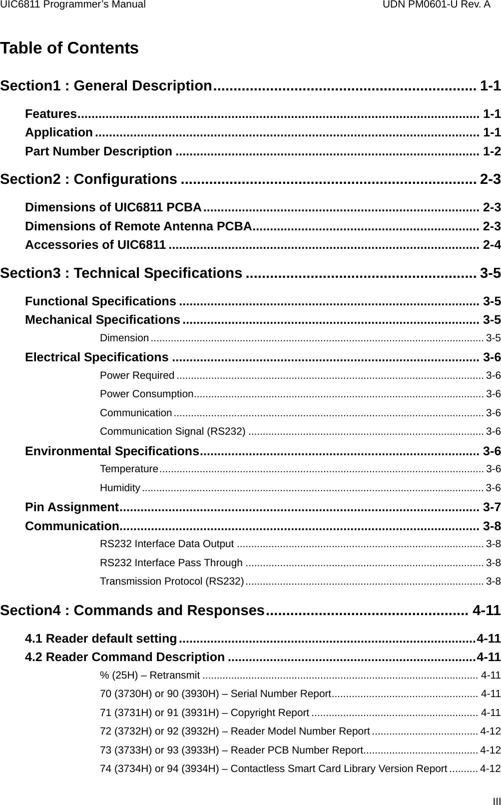
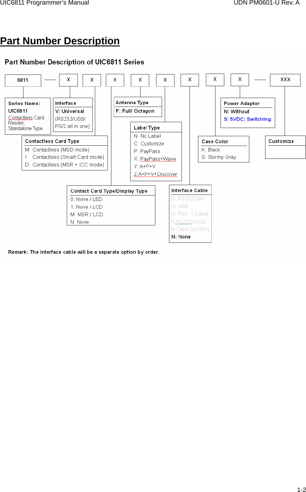
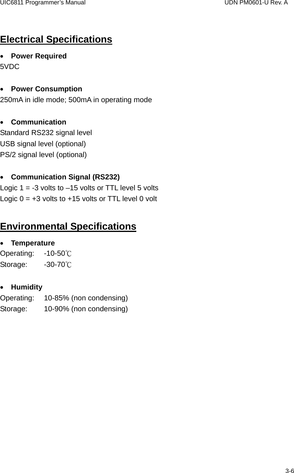
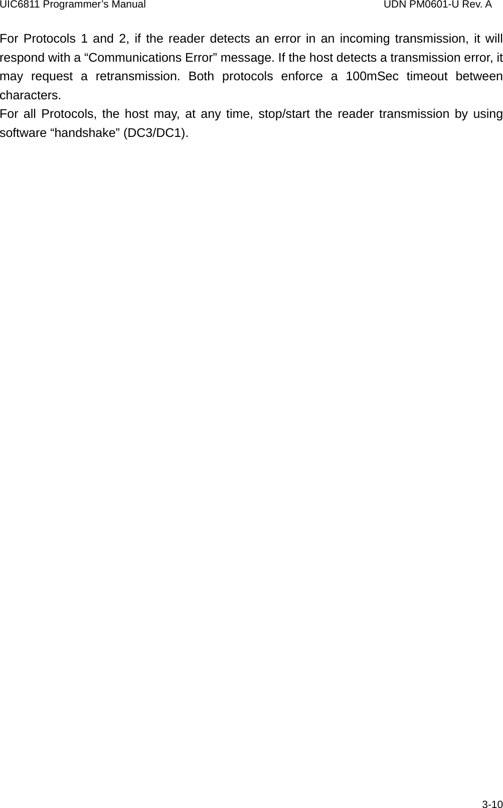
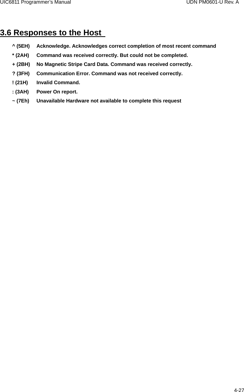
![UIC6811 Programmer’s Manual UDN PM0601-U Rev. A COMMENT Transmit the reader configuration data. The data from the reader configuration area will be transmitted to the host as hex values with the command “77” [offset] [num]. The reader will return any or all the bytes from the reader configuration. The offset is an optional byte and the available value is from 0x00 to 0x3F. The num is an optional byte specifying the number of configuration bytes to be returned. If the offset and length bytes are omitted then the current configuration starting at offset 0 is transmitted. Example: BE 0C 05 00 00 00 00 61 30 33 31 31 32 38 00 7D 28 54 4B 31 3A 3A 45 6E 64 29 28 54 4B 32 3A 3A 45 6E 64 29 28 54 4B 33 3A 3A 45 6E 64 29 00 00 00 00 00 00 00 00 00 00 3A 48 43 52 33 36 30 00 • 78 (3738H) or 98 (3938H) – Reader Customer Configuration Data Report COMMENT Transmit the reader customer configuration data. The data from the reader customer configuration area of the EEPROM will be transmitted to the host as hex values with the command “78¨ [offset] [num]. The reader will return any or all the bytes from the reader configuration. The offset is an optional byte and the available value is from 0x00 to 0x3F. The num is an optional byte specifying the number of configuration bytes to be returned. If the offset and length bytes are omitted then the current configuration starting at offset 0 is transmitted. Example: 31 30 30 30 30 30 30 30 33 36 30 2D 52 45 56 33 FF FF FF FF FF FF FF FF FF FF FF FF FF FF FF FF FF FF FF FF FF FF FF FF FF FF FF FF FF FF FF FF FF FF FF FF FF FF FF FF FF FF FF FF FF FF FF FF • 79 (3739H) or 99 (3939H) – Reader Manufacturing Configuration Data Report COMMENT Transmit the reader manufacturing configuration data. The data from the reader manufacturing configuration area of the flash will be transmitted to the host as hex values with the command “79” [offset] [num]. The reader will return any or all the bytes from the reader configuration. The offset is an optional byte and the available value is from 0x00 to 0x7F. The num is an optional byte specifying the number of configuration bytes to be returned to the host. If the offset and length bytes are omitted then the current configuration starting at offset 0 is transmitted. Example: BE 0C 05 00 00 00 00 61 30 33 31 31 32 38 00 79 00 00 00 00 00 00 00 00 00 00 00 00 00 00 00 00 00 00 00 00 00 00 00 00 00 00 00 00 00 00 00 00 00 00 00 00 00 00 00 00 3A 48 43 52 33 36 30 00 4-13](https://usermanual.wiki/Uniform/UIC6811/User-Guide-824658-Page-19.png)
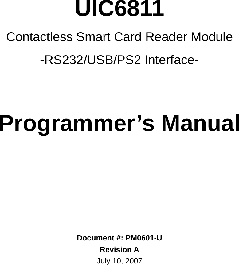
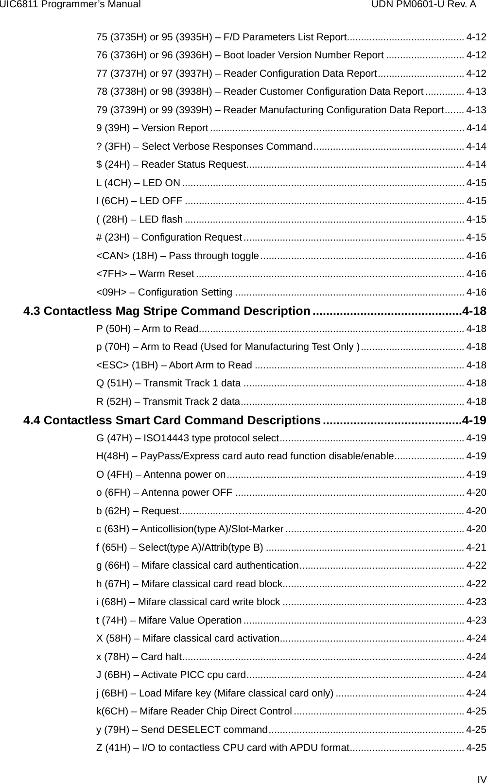
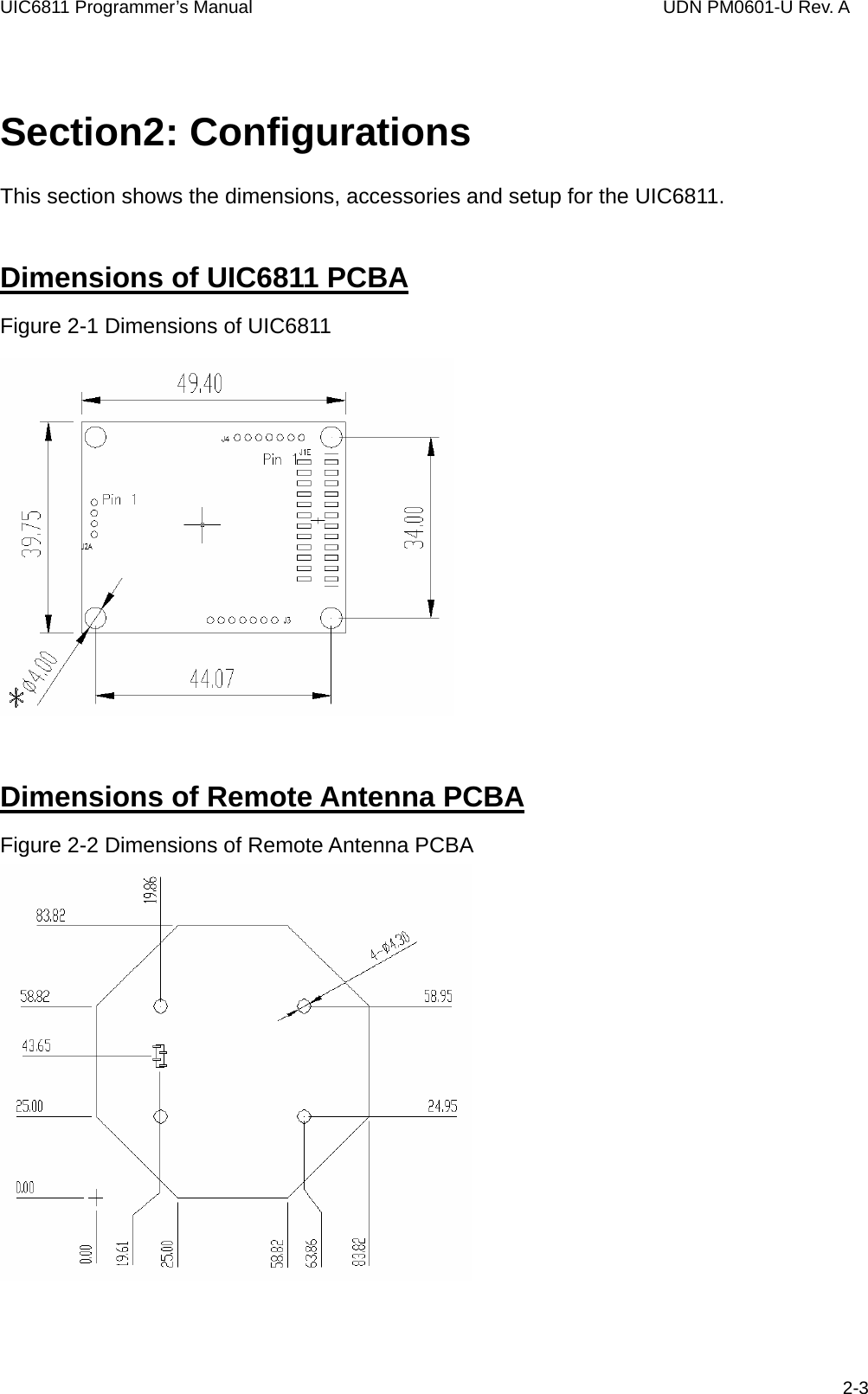
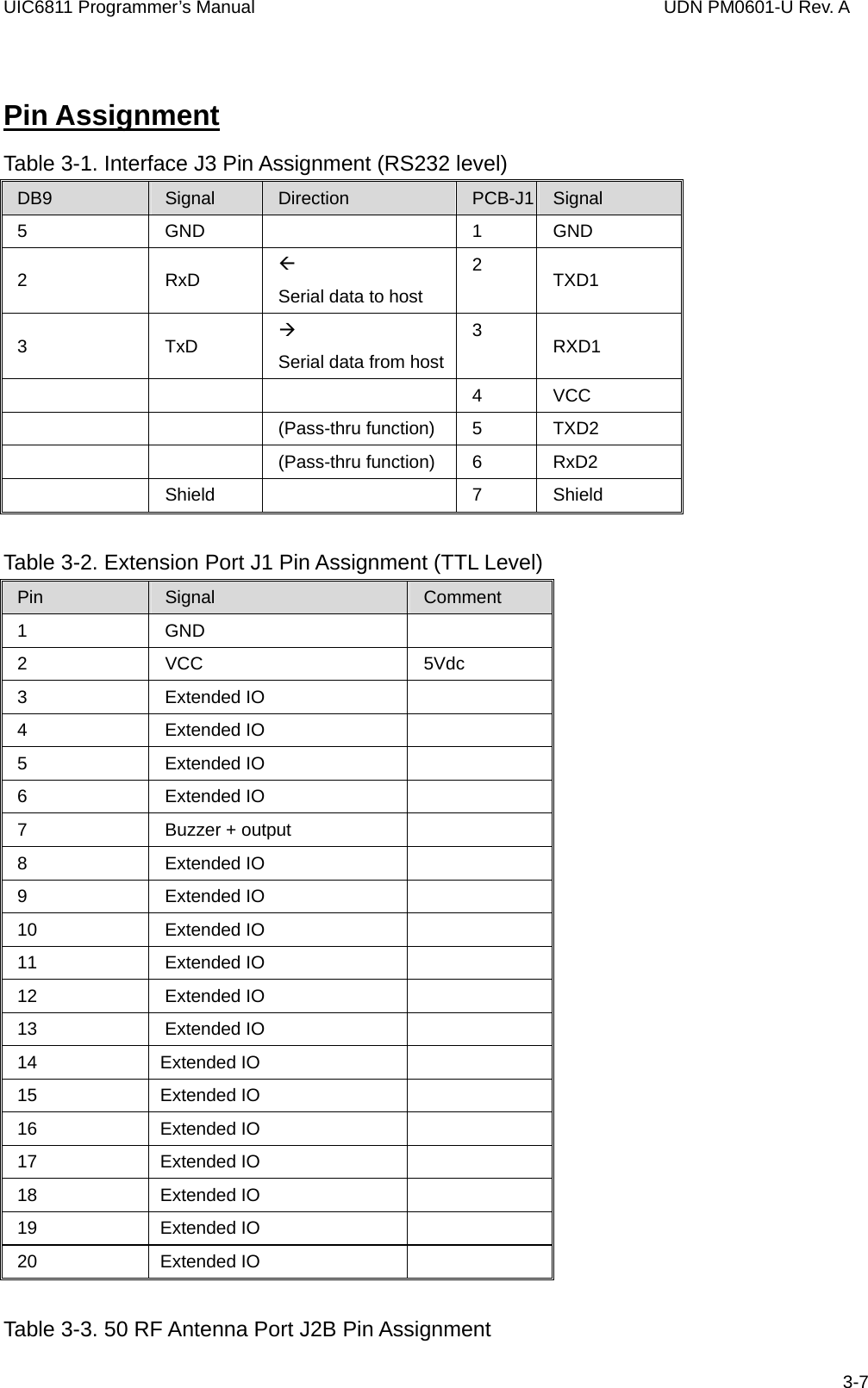
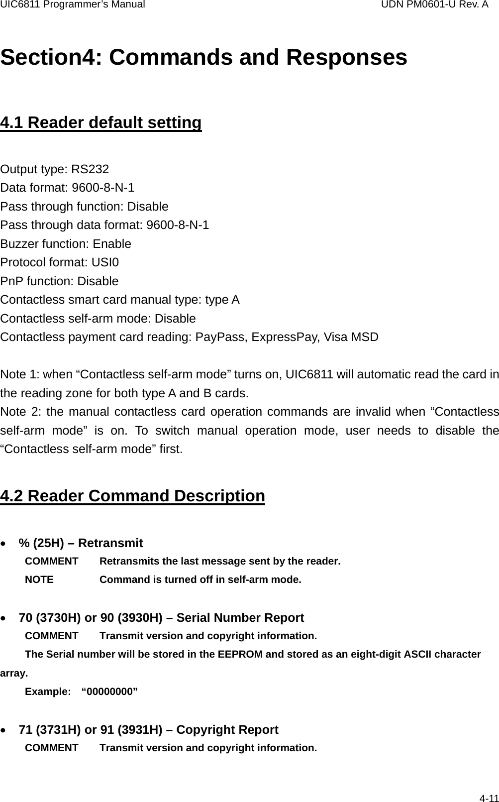
![UIC6811 Programmer’s Manual UDN PM0601-U Rev. A 4.4 Contactless Smart Card Command Descriptions • G (47H) – ISO14443 type protocol select COMMENT Select ISO 14443 type A or B which manual command operated. G[Type, 1 byte] [Type] 0 (30h, ASCII Hex) - ISO14443 A 1 (30h, ASCII Hex) - ISO14443 B Response: ‘^’ – acknowledgement ‘ *’ – No card response or No power on the antenna • H(48H) – PayPass/Express card auto read function disable/enable COMMENT Disable auto read function temporary if Self-Arm is enabling H [Enable/Disable, 1 byte] [Enable/Disable] 0 (30h, ASCII Hex) - Self-Arm disable 1 (31h, ASCII Hex) - Self-Arm enable Response: ‘^’ – acknowledgement ‘*’ – No card response or No power on the antenna • O (4FH) – Antenna power on COMMENT Apply power on the antenna. This command is for manual command operation. O[Baud rate, 1 byte] [Baud rate] (optional) 0 (30h, ASCII Hex) – 106K (default, Mifare type A only) 1 (31h, ASCII Hex) – 212K (Mifare type A only) 2 (32h, ASCII Hex) – 424K (Mifare type A only) 3 (33h, ASCII Hex) – 848K (Mifare type A only) 4-19](https://usermanual.wiki/Uniform/UIC6811/User-Guide-824658-Page-25.png)
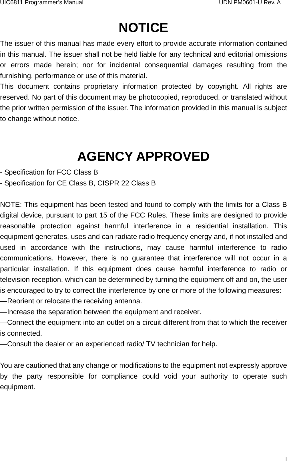
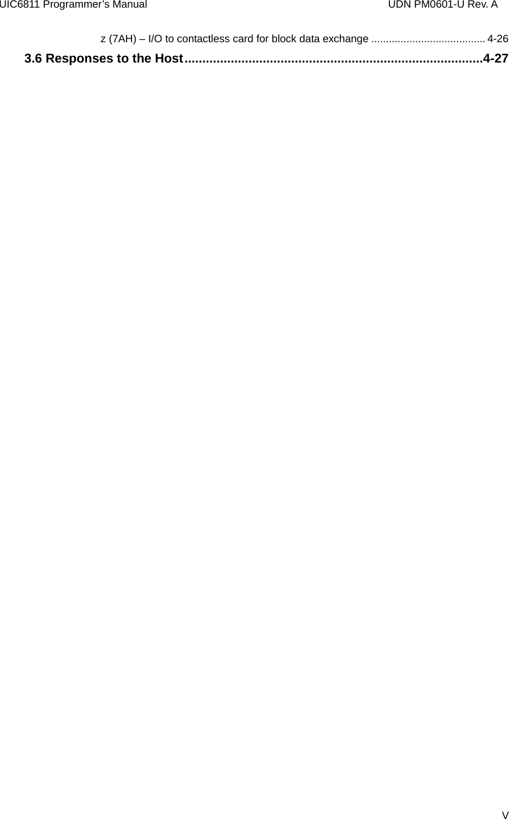
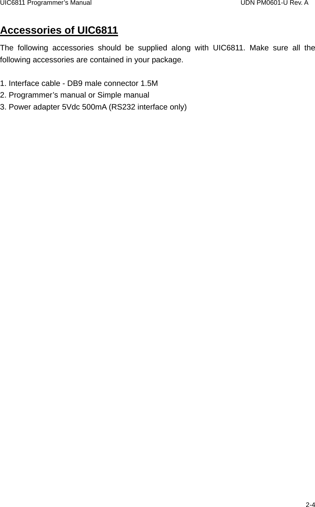
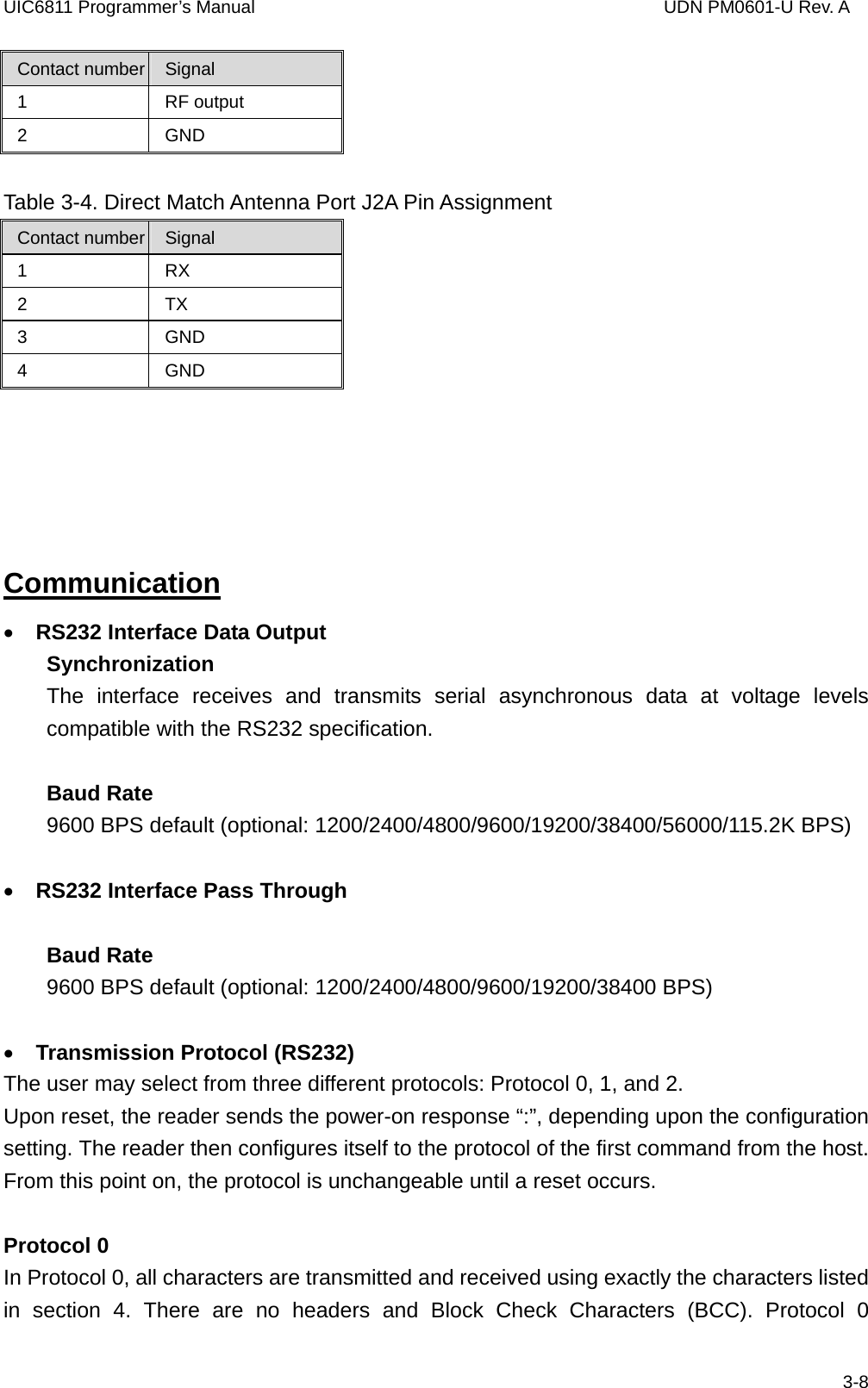
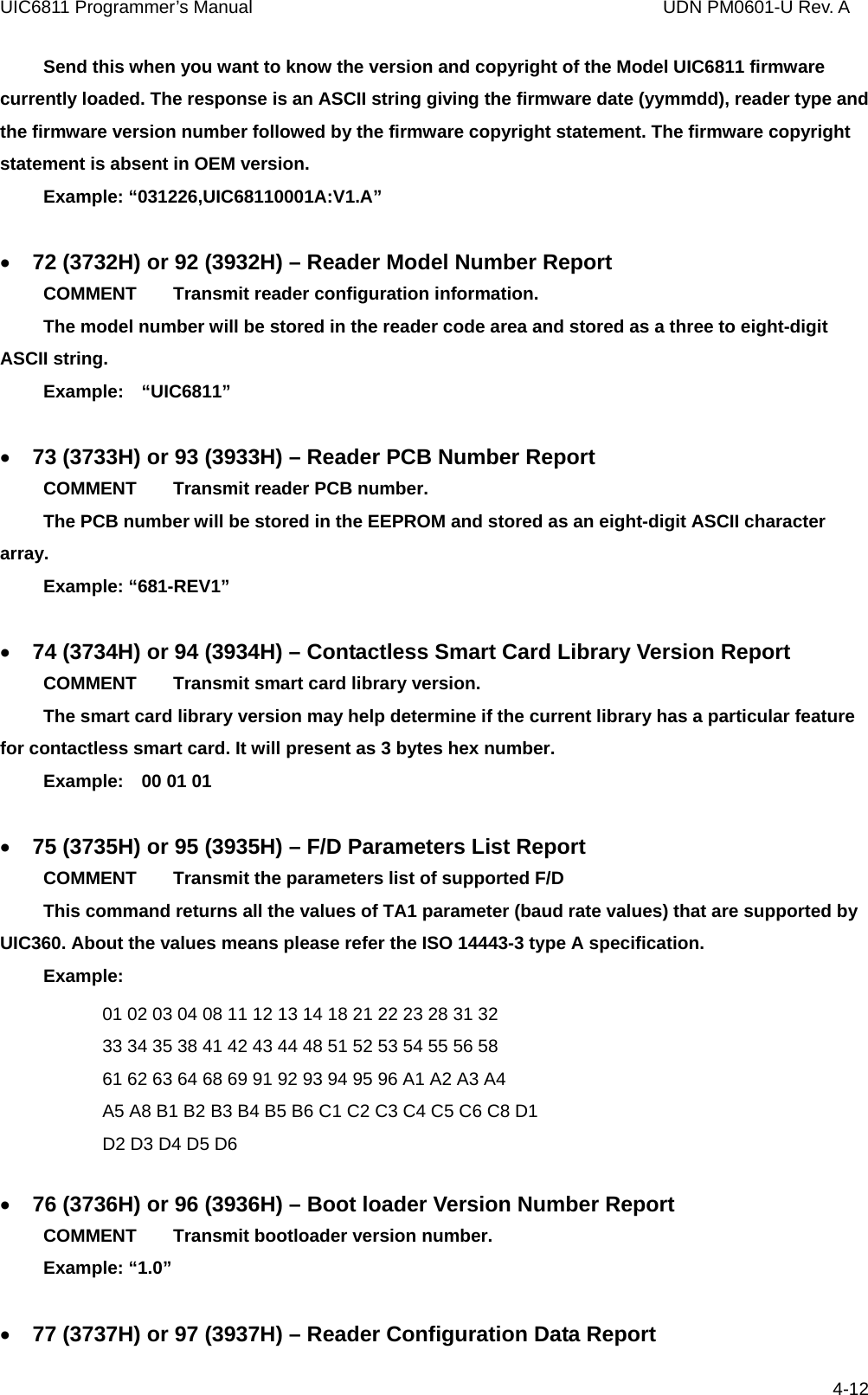
![UIC6811 Programmer’s Manual UDN PM0601-U Rev. A Response: ‘^’ – acknowledgement ‘*’ – Failed, the reader is in Self-Arm mode. The antenna power can not be turned off. • o (6FH) – Antenna power OFF COMMENT Turn the antenna power off. Response: ‘^’ – acknowledgement ‘*’ – Failed, the reader is in Self-Arm mode. The antenna power can not be turned off. • b (62H) – Request COMMENT Request command. b[Method, 1 byte] - If reader is set to ISO14443 type A [Method] (optional) 0 (30h, ASCII Hex) – Request All 1 (31h, ASCII Hex) – Request Idle Note: if the [Method] field does not appear in the request command, reader will set the request mode to “Request All” automatically. b[AFI, 1 byte][Parameter, 1 byte] - If reader is set to ISO14443 type B [AFI](optional) - Binary hex (00h to FFh), please refer to ISO 14443-3 for the detailed information [Parameter](optional) - Binary hex (00h to FFh), please refer to 14443 for the detailed information. Note: if the [AFI] and [Parameter] do not appear in the request command, reader will set the request mode to “Request All” automatically. Response: ATQA (2 bytes, type A, Binary Hex) or ATQB (16 bytes, type B, Binary Hex) if command executed successfully ‘*’ – No card response or No power on the antenna • c (63H) – Anticollision(type A)/Slot-Marker COMMENT In type A mode, the reader sends the Anticollision command to the card. 4-20](https://usermanual.wiki/Uniform/UIC6811/User-Guide-824658-Page-26.png)
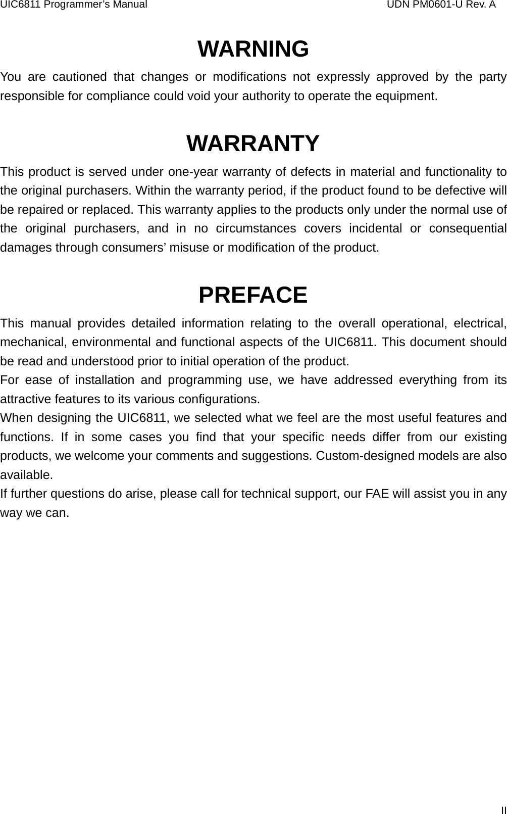
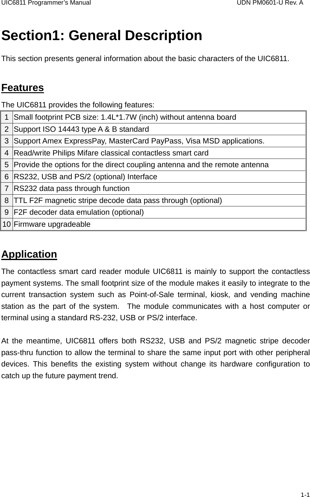
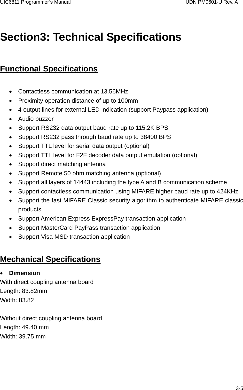
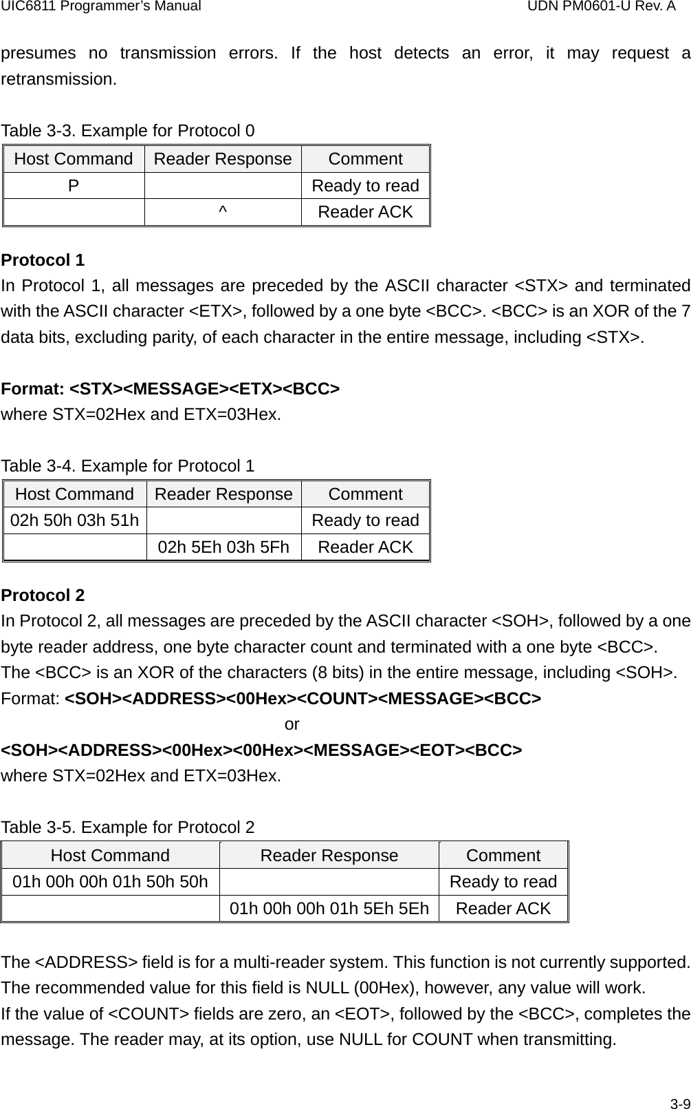
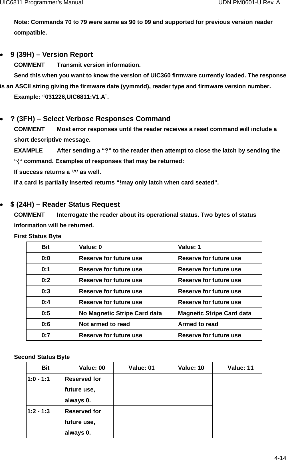
![UIC6811 Programmer’s Manual UDN PM0601-U Rev. A In type B mode, the reader sends the Slot-Marker command to the card. c[Cascade level, 1 byte] – if reader is set to type A [Cascade level](optional) 0(30h, ASCII Hex) – Level 1 1(31h, ASCII Hex) – Level 2 2(32h, ASCII Hex) – Level 3 Note: if [Cascade level] does not appear in the Anticollision command, the reader will set to Level 1 automatically. c[APn, 1 byte] – if reader is set to type B [APn] – Binary hex (01h to 16h), please refer to 14443-3 for the detailed information. Note: Slot-Marker is not a mandatory command for type B card. Response: If the command executed successfully, the reader returns PICC serial number for type A (4 bytes, Binary Hex) Or PICC send ATQB (12 bytes, Binary Hex) for type B (PICC may not response ATQB, in this situation, reader respone ‘*’) ‘*’ – No card response ‘~’ – No power on the antenna • f (65H) – Select(type A)/Attrib(type B) COMMENT In type A mode, the reader sends the SELECT command to the card. In type B mode, the reader sends the ATTRIB command to the card. f[Cascade level, 1 byte] – if reader is set to type A [Cascade level](optional) 0(30h, ASCII Hex) – Level 1 1(31h, ASCII Hex) – Level 2 2(32h, ASCII Hex) – Level 3 Note: if [Cascade level] does not appear in the Select command, the reader will set to Level 1 automatically. f[Parameter 1, 1 byte] [Parameter 2, 1 byte] [Parameter 3, 1 byte] [Parameter 4, 1 byte] – if reader is set to type B 4-21](https://usermanual.wiki/Uniform/UIC6811/User-Guide-824658-Page-27.png)
 – Binary Hex (00h to FFh) [Parameter 2](optional) – Binary Hex (00h to FFh) [Parameter 3](optional) – Binary Hex (00h to FFh) [Parameter 4](optional) – Binary Hex (00h to FFh) The setting of Parameter 1 to 4 should refer to ISO14443-3. If the [Parameter 1 – 4] do not appear in Attrib command, the reader set to default value. Response: If the command executed successfully, the reader returns ‘^’ + SAK( 1 byte) Or ‘^’ + MBLI/CID(1 byte) ‘*’ – No card response or No power on the antenna • g (66H) – Mifare classical card authentication (Support Mifare classical card only) COMMENT Mifare classical card authentication. f [Block number, 3 bytes][Key number, 1 byte] Authenticate the card with the key stored in EEPROM. Or f[Block number, 3 bytes][Key, 12 bytes] Authenticate the card with the key in [key field]. [Block number] 000 to 255 (30h30h30h to 32h35h35h, ASCII Hex) [Key number] 0 to 9 (30h to 39h, ASCII Hex) [Key] 0 to 9 or A to F (30h - 39h or 41h - 46h, ASCII Hex) Response: ‘^’ – acknowledgement ‘*’ – No card response or No power on the antenna • h (67H) – Mifare classical card read block (Support Mifare classical card only) COMMENT Mifare classical card read command. 4-22](https://usermanual.wiki/Uniform/UIC6811/User-Guide-824658-Page-28.png)
![UIC6811 Programmer’s Manual UDN PM0601-U Rev. A g [Block number, 3 bytes] [Block number] 000 to 255 (30h30h30h to 32h35h35h, ASCII Hex) Response: block data (16 bytes, Binary Hex) if command executed successfully ‘*’ – No card response or No power on the antenna • i (68H) – Mifare classical card write block (Support Mifare classical card only) COMMENT Mifare classical card write command. h[Block number, 3 bytes][Block data, 4 bytes or 16 bytes] [Block number] 000 to 255 (30h30h30h to 32h35h35h, ASCII Hex) [Block data] Binary Hex from 0h to FFh Note: 4 bytes block data are for Mifare Ultralight. Others should use 16 bytes block data. Response: ‘^’ – acknowledgement ‘*’ – No card response or No power on the antenna • t (74H) – Mifare Value Operation (Support Mifare classical card only) COMMENT Mifare classical card value operation command. t[Block number, 3 bytes][Operation mode, 1 byte][Value, 4 bytes] [Block number] 000 to 255 (30h30h30h to 32h35h35h, ASCII Hex) [Operation mode] 0 (30h, ASCII Hex) –Decrement 1 (31h, ASCII Hex) – Increment 2 (32h, ASCII Hex) – Restore [Value] Binary Hex from 0h to FFh 4-23](https://usermanual.wiki/Uniform/UIC6811/User-Guide-824658-Page-29.png)
![UIC6811 Programmer’s Manual UDN PM0601-U Rev. A Response: ‘^’ – acknowledgement ‘*’ – No card response or No power on the antenna • X (58H) – Mifare classical card activation (Support Mifare classical card only) COMMENT Perform request/anticollision/select command to activate the card. Response: ATQA/serial number (6 bytes, Binary Hex) if command executed successfully ‘*’ – No card response or No power on the antenna • x (78H) – Card halt COMMENT Card halt command. Response: ‘^’ – acknowledgement ‘*’ – No card response or No power on the antenna • J (6BH) – Activate PICC cpu card COMMENT Activate PICC cpu card command. The Antenna POWER ON command has to be sent first. Response: ATS (type A) or PUPI (type B) if command executed successfully ‘*’ – No card response or No power on the antenna • j (6BH) – Load Mifare key (Mifare classical card only) COMMENT Save up to 10 key sets for Mifare classical card application Note. For security reason, there is no way to retrieve the key back. i[Key number, 1 byte][Key data, 12 bytes] [Key number] 0 to 9 (30h to 39h, ASCII Hex) [Key data] 0 to 9 or A to F (30h - 39h or 41h - 46h, ASCII Hex) 4-24](https://usermanual.wiki/Uniform/UIC6811/User-Guide-824658-Page-30.png)
![UIC6811 Programmer’s Manual UDN PM0601-U Rev. A Response: ‘^’ – acknowledgement ‘*’ – No card response or No power on the antenna • k(6CH) – Mifare Reader Chip Direct Control COMMENT Direct control the internal setting of Mifare reader chip k[Command, 1 bytes] [Command] 0 (30h, ASCII Hex) - chip’s serial number. Return 4 bytes hex binary string 1 (31h, ASCII Hex) - chip’s product information field. Return 16 bytes hex binary string. 2 (32h, ASCII Hex) - chip’s register initial setting parameter. Return 32 bytes hex binary string. Response: ‘^’ – acknowledgement ‘*’ – No card response or No power on the antenna • y (79H) – Send DESELECT command COMMENT Send ISO14443 layer 4 DESELECT command to card Response: ‘^’ – acknowledgement ‘*’ – No card response or No power on the antenna • Z (41H) – I/O to contactless CPU card with APDU format COMMENT The command is used to pass an APDU to the card where both data and an ISO status are expected in the response. Z[APDU, variant, 262 bytes max] [APDU] Binary hex (00h to FFh) If an APDU is included with command it is transmitted to the ICC, otherwise an acknowledgement (“^” 5EH) is returned and the reader will wait until the APDU is sent in the following message. If successful, the data from the ICC and the two byte SW1/SW2 ISO 7816-4 response are returned. If unsuccessful, reader transmits '*'. APDU Command Structure CLA INS P1 P2 P3 Data 4-25](https://usermanual.wiki/Uniform/UIC6811/User-Guide-824658-Page-31.png)
![UIC6811 Programmer’s Manual UDN PM0601-U Rev. A Lc or Le (If Lc present) APDU Response Structure Data (optional) SW1 SW2 • z (7AH) – I/O to contactless card for block data exchange COMMENT The command is used to pass a block data to a card. z[CRC mode, 1 bytes][Wait time, 4 bytes][Block data, 384 bytes max.] [CRC mode] 0 (30h, ASCII Hex) – Block data contain 2 bytes CRC and enable CRC transmission. 1 (31h, ASCII Hex) – No CRC in block data and disable CRC transmission. [Wait time] 0000 to 9999 (30h30h30h30h to 39h39h39h39h, ASCII Hex) Waiting time in ms. [Block data] Binary hex (00h to FFh), Maximum accept 384 bytes. If successful, the data from the ICC are returned. If unsuccessful, reader transmits '*'. 4-26](https://usermanual.wiki/Uniform/UIC6811/User-Guide-824658-Page-32.png)