Unigen UGWR2USXXXX JUNO-LPA WIRELESSUS RADIO MODULE User Manual USBW Datasheet RT1236v096
Unigen Corporation JUNO-LPA WIRELESSUS RADIO MODULE USBW Datasheet RT1236v096
Unigen >
Contents
- 1. Manual fraft
- 2. Advertising literature
Advertising literature
WirelessUSB™ - UGWR2US
Solutions for a Real Time World Data Sheet
Re-Tek - 1236 1 45388 Warm Springs Blvd. Fremont, CA 94539
support@unigen.com TEL: (510) 668.2088 FAX: (510) 661.2788
http://www.unigen.com Toll Free: (800) 826.0808
Copyright Unigen Corporation, 2004
UNIGEN CORP. WIRELESS MODULE PRODUCTS
PART NUMBER FAMILY:
UGWR2US SERIES
JUNO-LPA WIRELESSUSB™ RADIO MODULE
Issue Date: 17 June 2004
Revision: 0.96
Revision History
Rev. No. History Issue Date Remarks
0.80 Draft Release 4 May 2004
0.81 Eng. Rev. 0.01 19 May 2004 Pin assignment, radio characteristics update
0.82 Eng. Rev. 0.02 4 June 2004 Electrical Characteristics update
0.90 Final Draft 10 June 2004 Radio Parameters Update, final draft text
0.91 FDraft Revised 11 June 2004 Minor text corrections
0.95 FDraft Revised 2 15 June 2004 Update Reference Documents, Functional Description
0.96 FDraft Revised 3 17 June 2004 Minor text corrections
THIS DOCUMENT IS PROVIDED “AS IS” WITH NO WARRANTIES WHATSOEVER,
INCLUDING ANY WARRANTY OF MERCHANTABILITY, NON-INFRINGEMENT, FITNESS
FOR ANY PARTICULAR PURPOSE, OR ANY WARRANTY OTHERWISE ARISING OUT OF
ANY PROPOSAL, SPECIFICATION OR SAMPLE.
Unigen Corporation disclaims all liability, including liability for infringement of any
proprietary rights, relating to use of information in this document. No license,
expressed or implied, by estoppel or otherwise, to any intellectual property rights is
granted herein.
*Third-party brands, names, and trademarks are the property of their respective
owners.
Copyright
©
Unigen Corporation, 2004

WirelessUSB™ - UGWR2US
Solutions for a Real Time World Data Sheet
Re-Tek - 1236 2 45388 Warm Springs Blvd. Fremont, CA 94539
support@unigen.com TEL: (510) 668.2088 FAX: (510) 661.2788
http://www.unigen.com Toll Free: (800) 826.0808
Copyright Unigen Corporation, 2004
TABLE OF CONTENTS:
REFERENCE DOCUMENTATION: 3
INTRODUCTION: 3
FEATURES: 4
DESCRIPTION: 4
FUNCTIONAL BLOCK DIAGRAM: 5
ABSOLUTE MAXIMUM RATINGS 6
RECOMMENDED OPERATING CONDITIONS: 6
DC ELECTRICAL CHARACTERISTICS: 7
Table 1 – Electrical Characteristics 7
ANTENNA: 7
Table 2 – Antenna Characteristics 7
RADIO PARAMETERS: 8
Table 3 – Radio Characteristics 8
PIN ASSIGNMENTS: 9
Table 4 – JUNO-LPA Pin Assignments 9
PIN FUNCTIONS: 9
AGENCY CERTIFICATIONS: 11
Regulatory Agencies: 11
Table 5 – Regulatory Agency Certifications 11
Regulatory Compliance Statement: 12
MECHANICAL CHARACTERISTICS: 12
Table 6 – Mechanical Description 12
MECHANICAL DRAWINGS: 13
Figure 1 – Juno-LPA Land Pattern 13
Figure 2 – Juno-LPA Mirrored Land Pattern 14
PHYSICAL DIMENSIONS: 15
Figure 3 – Juno-LPA Dimensions 15
Figure 4 – Juno-LPA Mirrored Dimensions 16
ORDERING INFORMATION:* 17
JUNO-LPA WirelessUSB™ Module 17
Antennae 17
CONTACT INFORMATION 18
CORPORATE HEADQUARTERS 18

WirelessUSB™ - UGWR2US
Solutions for a Real Time World Data Sheet
Re-Tek - 1236 3 45388 Warm Springs Blvd. Fremont, CA 94539
support@unigen.com TEL: (510) 668.2088 FAX: (510) 661.2788
http://www.unigen.com Toll Free: (800) 826.0808
Copyright Unigen Corporation, 2004
REFERENCE DOCUMENTATION:
The Unigen JUNO-LPA WirelessUSB™ UGWRL2US module adaptation of the Cypress
Semiconductor CYWUSB6935 LR 2.4GHz DSSS Radio SOC with the addition of a power
amplifier is represented in this document. The detail provided is information for using JUNO-
LPA in a digital electronic device and is only a “companion” document to Cypress
Semiconductors’ documentation for the above noted part.
The CYWUSB6935 LR 2.4GHz DSSS Radio SOC information and technical details (ex. register
settings, timing, application interfaces, clocking and power management, etc.) may be
obtained from the Cypress Semiconductor web site or contacting Cypress’s authorized sales
representatives.
The following is a list of required documents and locations known at the time of publication
that accompany this datasheet.
• The CYWUSB6935 LR 2.4GHz DSSS Radio SOC Datasheet – CUWUSB6935.pdf
http://www.cypress.com/cfuploads/img/products/cywusb6935.pdf
• The JUNO-LPA WirelessUSB™ Radio Module User Manual – USBWR2US User
Manual_v10.pdf
http://www.unigen.com/download/USBWR2US%20User%20Manual_v0911.pdf
Additional documentation for the Cypress Semiconductor CYWUSB6935 LR 2.4GHz DSSS Radio
SOC device and the Unigen JUNO-LPA WirelessUSB™ UGWRL2US module may be obtained by
contacting agents or representatives of the respective companies.
INTRODUCTION:
Unigen JUNO-LPA WirelessUSB™ UGWRL2US modules represent the convergence of emerging
wireless connectivity solutions and the USB “Plug-N-Play” ease of operation. WirelessUSB, as
created by Cypress Semiconductor, is a low-cost, 2.4GHz communication protocol designed for
use in commercial, industrial, consumer, and computer product applications needing highly
reliable data connectivity.
JUNO-LPA modules combine Cypress Semiconductor’s wireless and USB expertise with
Unigen’s module design, manufacturing, and testing proficiency to create production ready,
pre-certified modules that are easily integrated into existing, and new product designs.
JUNO-LPA modules offer immediate, drop-in design solutions and use the native Operating
System HID drivers to seamlessly enumerate and operate mouse, keyboard, and gaming
devices, or other devices using the HID specification for communication with the host systems.

WirelessUSB™ - UGWR2US
Solutions for a Real Time World Data Sheet
Re-Tek - 1236 4 45388 Warm Springs Blvd. Fremont, CA 94539
support@unigen.com TEL: (510) 668.2088 FAX: (510) 661.2788
http://www.unigen.com Toll Free: (800) 826.0808
Copyright Unigen Corporation, 2004
FEATURES:
• CYWUSB6935 LR 2.4GHz DSSS Radio SOC
• Operates in the 2.4 to 2.483GHz,
unlicensed frequency range
(ISM – Industrial, Scientific and Medical)
• -95dBm receive sensitivity
• Up to +23dBm Output Power
• Range of up to 1000+ meters with
appropriate antenna
• Data Rate of 62.5kbits/sec
• SPI interface
(up to 2MHz data rate)
• Operating Voltage Requirement
2.7 – 3.6Vdc
• Dual DSSS reconfigurable Baseband
Correlators
• Small PCBA Design:
UGWR1US
1.29″ (32.76mm) by 1.30″ (33.02mm)
• Complete Radio Module
Just add a tested antenna.
PN. – UGADL1B1M1 or UGADA0B1M1
• Agency Pre-Certification
FCC/EU/ETSI/Industry Canada
Module certified to FCC/EU compliance
specifications limiting your agency compliance
time and cost.
• FCC Radio Certification
Grandfathered to end-device manufactures
DESCRIPTION:
JUNO-LPA WirelessUSB™UGWR2US Module
is a tightly integrated, low-cost, high-
reliability 2.4GHz TX/RX radio module for
use in commercial, industrial, consumer,
and computer product applications.
JUNO-LPA uses the Cypress Semiconductor
CYWUSB6935 LR 2.4GHz DSSS Radio SOC
device coupled with precise RF power
amplifier to achieve highly reliable data
communication at 1000 meter distances.
JUNO-LPA is a complete solution requiring
only integration into an existing, or new
device. A WirelessUSB device may require
no additional software drivers, as it can use
the OS native USB device drivers to enable
supported device classes.
JUNO-LPA is less than 1.5”sq and is
available for horizontal or vertical mounting
directly to the device PCB. JUNO-LPA is
also available in bare-board configuration
for alternate application.
Regulatory Compliance:
JUNO-LPA modules are 100% tested for
functional operation and pre-certified for
regulatory compliance. The JUNO-LPA is
FCC certified for “Modular Approval”.
Details for product application and use of
this certification are noted in the JUNO-LPA
User Manual. Digital electronic device
makers need only submit to the appropriate
agencies for their customary certification.
JUNO-LPA is certified for operation with an
antenna of up to 2db gain, and the
certification is available from the Federal
Communications Commission web site for
documentation purposes. Approved
antennae, noted in the Ordering Section are
available from Unigen.
WirelessUSB™ - UGWR2US
Solutions for a Real Time World Data Sheet
Re-Tek - 1236 5 45388 Warm Springs Blvd. Fremont, CA 94539
support@unigen.com TEL: (510) 668.2088 FAX: (510) 661.2788
http://www.unigen.com Toll Free: (800) 826.0808
Copyright Unigen Corporation, 2004
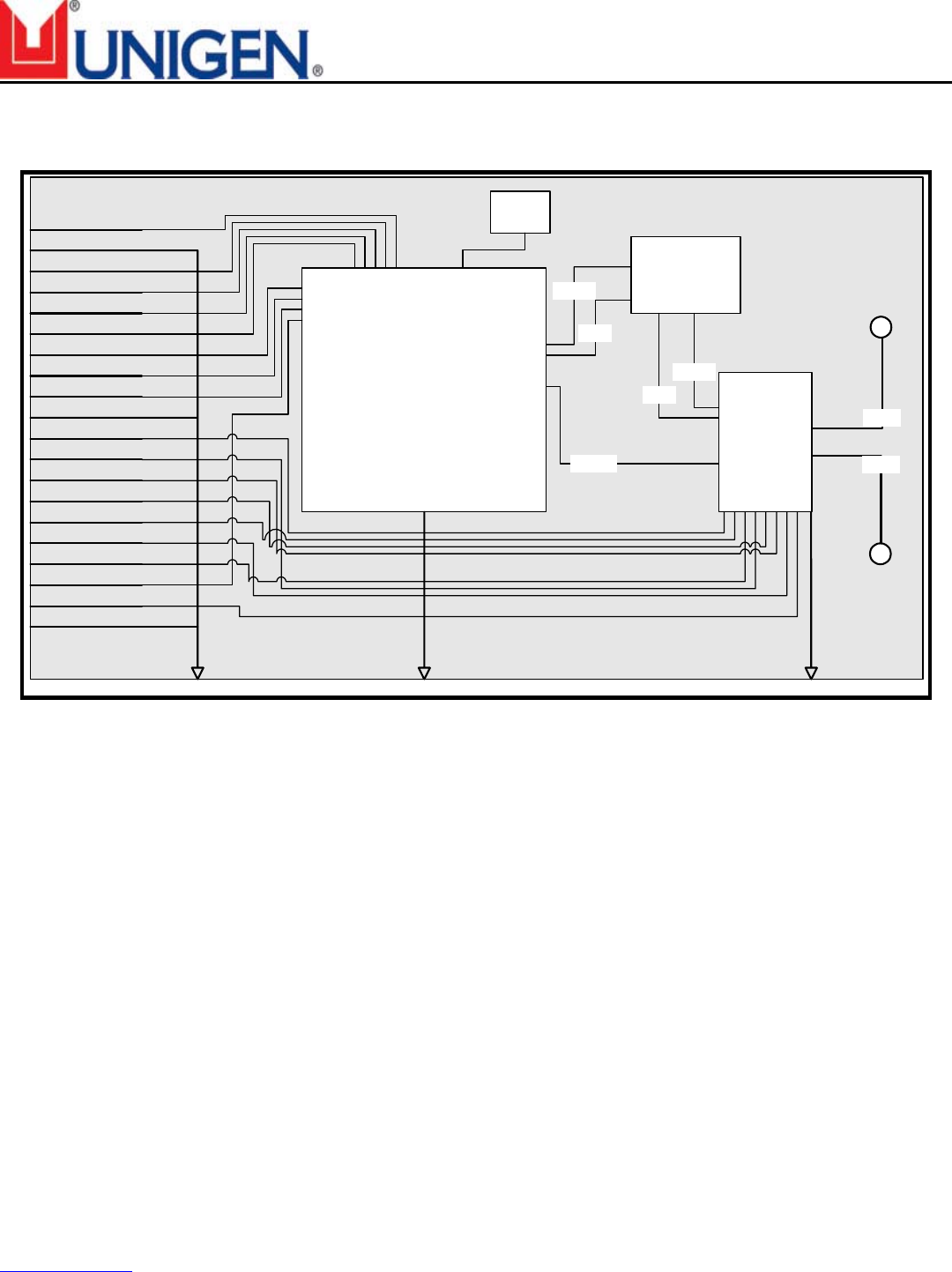
FUNCTIONAL BLOCK DIAGRAM:
JUNO-LPA Functional Block Diagram
CYWUSB6935
WirelessUSBTM Radio SOC
Baseband and RF Function
Pin 1
20
PDn
VCC_AMP
GND
GND
GND
19
18
17
16
15
14
13
12
11
10
9
8
7
6
5
4
3
2
MISO
MOSI
X13OUT
SCK
RSTn
SSn
IRQ
VCC
VDET
TST
TX2
RX2
TX1
RX1
SLOPE SEL
ANT 1
ANT 2
Power
Amplifier
RF Out
RF In
PA CTL
RF Filter
Circuitry
RF In
RF Out
XTAL
WirelessUSB™ - UGWR2US
Solutions for a Real Time World Data Sheet
Re-Tek - 1236 6 45388 Warm Springs Blvd. Fremont, CA 94539
support@unigen.com TEL: (510) 668.2088 FAX: (510) 661.2788
http://www.unigen.com Toll Free: (800) 826.0808
Copyright Unigen Corporation, 2004
ABSOLUTE MAXIMUM RATINGS:
Symbol Definition Min. Max. Unit
VCC Supply Voltage – Radio SOC -0.3 3.9 VDC
VCC_AMP Supply Voltage – Power Amplifier -0.3 3.9 VDC
SLOPE_SEL Slope Select Pin -0.3 3.9 VDC
TOC Commercial Operating Temperature Range -20 70 °C
TOI Industrial Operating Temperature Range -40 85 °C
TS Storage Temperature Range -40 125 °C
VLI VDC to Logic Inputs -0.3 VCC + 0.3 VDC
V O/Hi-Z VDC to Outputs in Hi-Z state -0.3 VCC + 0.3 VDC
SDVD Static Discharge Voltage Digital >4000 VDC
SDVR Static Discharge Voltage RF >4000 VDC
These are stress ratings only. Exposure to stresses beyond these maximum ratings may
cause permanent damage to, or affect the reliability of this module. Avoid using the module
outside the recommended operating conditions defined below. This module is ESD sensitive
and should be handled and/or used in accordance with proper ESD mitigation.
RECOMMENDED OPERATING CONDITIONS:
Value
Symbol Description Min. Typ.* Max. Unit
VCC Supply Voltage 2.7 3.0 3.6 VDC
TOC Commercial Operating Temperature Range -20 25 70 °C
TOI Industrial Operating Temperature Range -40 25 85 °C
GND Ground Voltage 0 VDC
WirelessUSB™ - UGWR2US
Solutions for a Real Time World Data Sheet
Re-Tek - 1236 7 45388 Warm Springs Blvd. Fremont, CA 94539
support@unigen.com TEL: (510) 668.2088 FAX: (510) 661.2788
http://www.unigen.com Toll Free: (800) 826.0808
Copyright Unigen Corporation, 2004
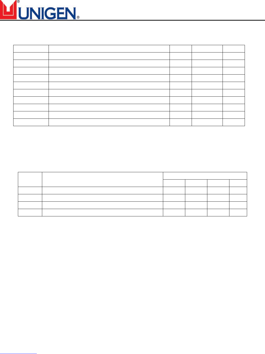
DC ELECTRICAL CHARACTERISTICS:
Value
Symbol Description Condition(s) Min. Typ.* Max. Unit
VCC Supply Voltages 2.7 3.0 3.6 VDC
VOH1 Voltage Output High 1 At IOH = –100.0µA VCC-0.1 VCC VDC
VOH2 Voltage Output High 2 At IOH = –2.0 mA 2.4 3.0 VDC
VOL Voltage Output Low At IOL = 2.0 mA 0.0 0.4 VDC
VIH Voltage Input High 2.0 VCC VDC
VIL Voltage Input Low -0.3 0.8 VDC
IIL Input Leakage Current 0 < VIN < VCC -1 0.30 +1 µA
ISLEEP Power-down current consumption PD = Low 3.26 10 µA
TX AVG ICC1 Mean transmitter current consumption 1no handshake 6.0 mA
TX AVG ICC2 Mean transmitter current consumption 2w/handshake 10.0 mA
RX ICC (Peak) Current consumption during receive 60.0 mA
TX ICC (Peak) Current consumption during transmit 140 170 mA
MTBF Calculated >87,600 Hours
Table 1 – Electrical Characteristics
*= Measured with 3.0VCC at 25ºC
1= Mean Icc when transmitting a 5-byte packet (3 data bytes + 2 bytes of protocol) every 10ms using
the Wireless USB LS 1-way protocol.
2= Mean Icc when transmitting a 5-byte packet (3 data bytes + 2 bytes of protocol) every 10ms using
the Wireless USB LS 2-way protocol.
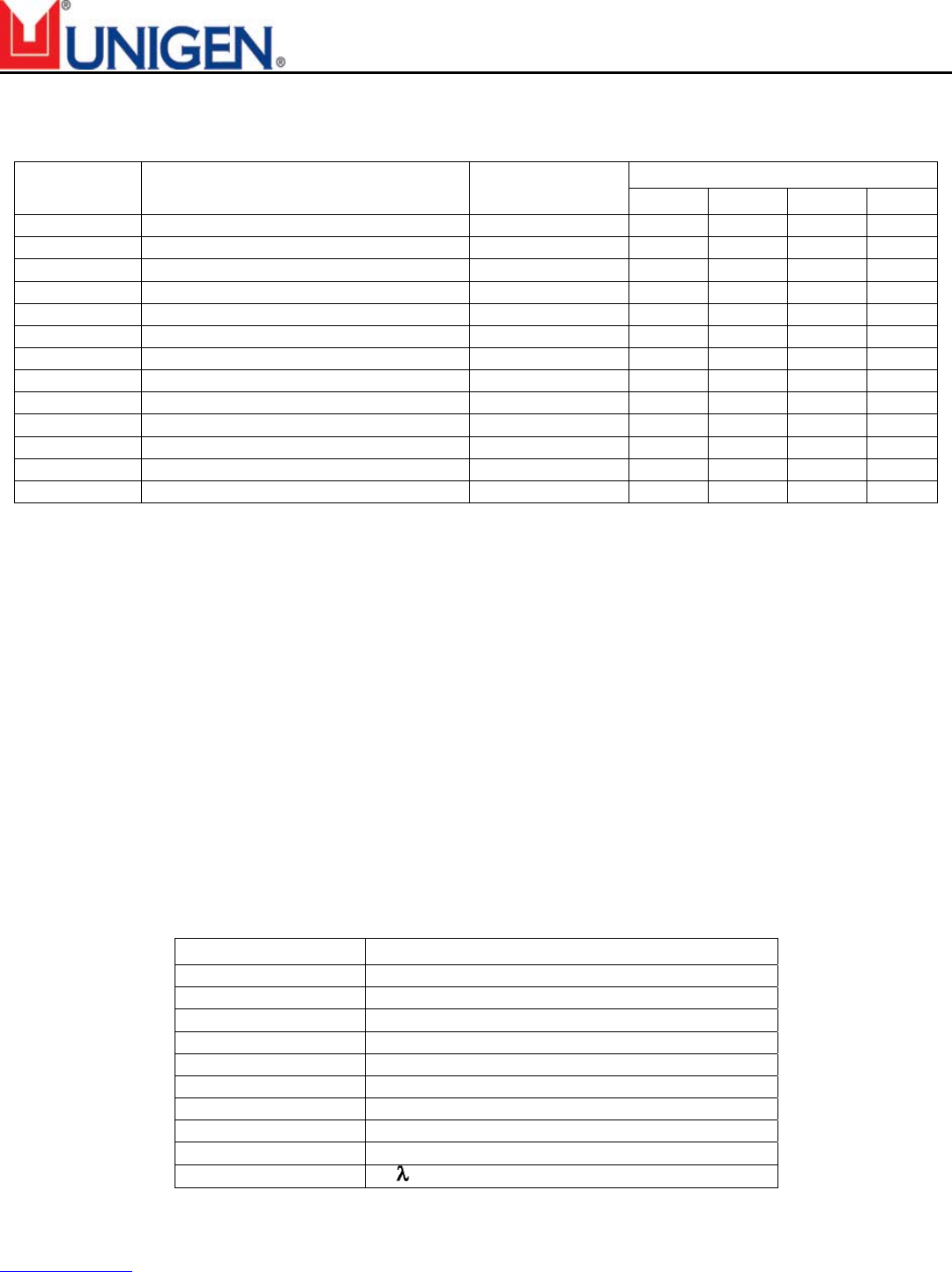
ANTENNA:
JUNO-LPA requires the addition of at least on antenna for radio operation. JUNO-LPA achieved
FCC “Modular Approval” for use in Digital Electronic Devices in combination with the noted
antennae. Use of antennae other than these listed can required recertification of the module in
the end-product. (See “Agency Certification” in this document for brief information). The
JUNO-LPA WirelessUSB™ Radio Module User Manual
contains complete regulatory
compliance information.
Customers may obtain antennae (part numbers UGADL1B1M1 or UGADA0B1M1) with the
following properties:
Item Property
Coaxial Cable Type 4.13mm high freq.
Cable Length 11.81” (300mm) – other lengths available
Connector Mini Coaxial
Frequency Range 2.4000~2.4835GHz
Impedance 50Ω (Typ.)
VSWR 2.0 max. over full range of operation
Return Loss -10dB max.
Gain 2.0dBi - calculated
Maximum Power 1W
Electrical Wave ½Dipole
Table 2 – Antenna Characteristics
WirelessUSB™ - UGWR2US
Solutions for a Real Time World Data Sheet
Re-Tek - 1236 8 45388 Warm Springs Blvd. Fremont, CA 94539
support@unigen.com TEL: (510) 668.2088 FAX: (510) 661.2788
http://www.unigen.com Toll Free: (800) 826.0808
Copyright Unigen Corporation, 2004
RADIO PARAMETERS:
Parameter Description Condition Min. Typ. Max Unit
RF Frequency Range 2.400 2.483 GHz
Radio Receiver (T = 25ºC, VCC = 3.3V, fosc = 13.000MHz, X13OUT off, 64 chips/bit, Threshold Low = 8, Threshold High = 56, BER ≤10-3
Sensitivity -95 dBm
Maximum Received Signal -20 -10 dBm
RSSI Value for PWRin >-40dBm 28-31
RSSI Value for PWRin <-95dBm 0-10
Interference Performance
Co-channel Interference rejection Carrier-to-Interference (C/I) C = –60 dBm 11 dB
Adjacent (1 MHz) channel selectivity C/I 1 MHz C = –60 dBm 3 dB
Adjacent (2 MHz) channel selectivity C/I 2 MHz C = –60 dBm -30 dB
Adjacent (> 3 MHz) channel selectivity C/I > 3 MHz C = –67 dBm -40 dB
Image[22] Frequency Interference, C/I Image C = –67 dBm -20 dB
Adjacent (1 MHz) interference to in-band image frequency, C/I
image ±1 MHz
C = –67 dBm -25 dB
Out-of-band Blocking Interference Signal Frequency
30MHz – 2399MHz except (FO/N & FO/N± 1MHz) C = –67 dBm -30 dBm
2498MHz – 12.75GHz, except (FO*N & FO*N±1MHz) C = –67 dBm -20 dBm
Intermodulation C = –67 dBm, ∆f = 5, 10MHz -39 dBm
Spurious Emission
30MHz – 1GHz -57 dBm
1GHz – 12.75GHz (except 4.8GHz – 5.0GHz) -47 dBm
4.8GHz – 5.0GHz -37 dBm
Radio Transmitter (T = 25ºC, VCC = 3.3V, fosc = 13.000MHz)
Maximum RF Transmit Power PA = 7 0 dBm
RF Power Control Range 30 dB
RF Power Range Control Step Size Seven steps, monotonic 4.3 dB
Frequency Deviation PN Code Pattern 10101010 270 kHz
Frequency Deviation PN Code Pattern 11110000 320 kHz
Zero Crossing Error ±125 ns
Occupied Bandwidth 100-kHz resolution bandwidth, -6dBc 500 kHz
Initial Frequency Offset ±75 kHz
In-Band Spurious
Second Channel Power (±=2MHz) -30 dBm
≥ Third Channel Power (≥3 MHz) -40 dBm
Non-Harmonically Related Spurs
30MHz – 12.75GHz -57 dBm
Harmonic Spurs
Second Harmonic -20 dBm
Third Harmonic -30 dBm
Fourth and Greater Harmonics -47 dBm
Table 3 – Radio Characteristics

WirelessUSB™ - UGWR2US
Solutions for a Real Time World Data Sheet
Re-Tek - 1236 9 45388 Warm Springs Blvd. Fremont, CA 94539
support@unigen.com TEL: (510) 668.2088 FAX: (510) 661.2788
http://www.unigen.com Toll Free: (800) 826.0808
Copyright Unigen Corporation, 2004
PIN ASSIGNMENTS:
Pin# Function I/O Description
1 PDn I Power Down
2 GND - Module Ground
3 SCK I SPI Input Clock
4 X13OUT O/Hi-Z Output Clock
5 MOSI I SPI Data Input from MCU
6 MISO O/Hi-Z SPI Data Output to MCU
7 IRQ O Interrupt Request
8 SSn I SPI Slave Select Enable
9 RSTn I Module Reset
10 GND - Module Ground
11 RX2 I Antenna 2 RX Control
12 TX2 I Antenna 2 TX Control
13 TST O Internal Test Pin for VREG monitor of PA
14 VDET O Power Detect Output
15 RX1 I Antenna 1 RX Control
16 SLOPE SEL I Positive/Negative Slope Detection
17 TX1 I Antenna 1 TX Control
18 Vcc - Module Input Power
19 Vcc_AMP - Power supply to Power Amp Circuitry
20 GND - Module Ground
Table 4 – JUNO-LPA Pin Assignments
PIN FUNCTIONS:
MOSI: SPI Input from MCU
Receives commands/data from the device microcontroller.
MISO: SPI Output to MCU
Transmits requests/data to the device microcontroller.
SSn: SPI Slave Select Enable Input
SPI enable
IRQ: Interrupt Request
The Interrupt Request Pin Select bits are used to determine the drive
method of the IRQ pin
GND: Module Ground
Ground to equal 0Vdc

WirelessUSB™ - UGWR2US
Solutions for a Real Time World Data Sheet
Re-Tek - 1236 10 45388 Warm Springs Blvd. Fremont, CA 94539
support@unigen.com TEL: (510) 668.2088 FAX: (510) 661.2788
http://www.unigen.com Toll Free: (800) 826.0808
Copyright Unigen Corporation, 2004
RSTn: Module Reset
Active LOW reset switch
SCK: SPI Input Clock
X13OUT: System Clock
On-board XTL clock output of 13MHz
PACTL: Power Amplifier Control
Enables/disables external power amplification circuitry, where available
PDn: Power Down
Driving signal LOW will put the module in SUSPEND MODE (X13OUT =
0 when PDn is LOW)
Vcc: Module Input Power
Vcc range 2.7 to 3.6Vdc
Vcc_AMP: Power supply input for power amplifier
TX1: Transmit Antenna #1
Input for control of TX Antenna #1
TX2: Transmit Antenna #2
Input for control of TX Antenna #2
RX1: Receive Antenna #1
Input for control of RX Antenna #1
RX2: Receive Antenna #2
Input for control of RX Antenna #2
SLOPE SEL: Positive/Negative Slope Select
Input for determining positive or negative slope of VDET
VDET: Power Detect Output
Power output voltage detector
TST: Internal Test Pin for VREG monitor of PA
Output from power amplifier for monitoring the internal voltage
regulator
WirelessUSB™ - UGWR2US
Solutions for a Real Time World Data Sheet
Re-Tek - 1236 11 45388 Warm Springs Blvd. Fremont, CA 94539
support@unigen.com TEL: (510) 668.2088 FAX: (510) 661.2788
http://www.unigen.com Toll Free: (800) 826.0808
Copyright Unigen Corporation, 2004
AGENCY CERTIFICATIONS:
The Unigen JUNO-LPA UGWR2US WirelessUSB Module is tested and pre-certified for compliance with
applicable Federal and International Regulatory Agency requirements. JUNO-LPA has received a
“Modular Approval” certification for the radio function. This certification may be used by the Digital
Electronic Device manufacturer by grant for the end-device containing JUNO-LPA. The grant is only
applicable to the module’s radio function in the end-product and does not supplant the other regulatory
agency requirements concerning digital emissions certifications, where required. Contact the appropriate
regulatory agency for relevant product requirements as needed.
The
Unigen JUNO-LPA UGWR2US WirelessUSB Module User Manual
contains information
concerning the digital and analog emissions testing and details application of the “Modular Approval”
grant. The table below summarizes the regulatory agency tests performed for receipt of respective
certifications.
Regulatory Agencies:
Agency Test Performed Type Limit Result Margin
30-12.75MHz Transmit Mode EN 300 328 PASS -4.6dB @ 4804MHz
EU Radiated Spurious
Emissions 30-12.75MHz Transmit Mode EN 300 328 PASS -4.9 @ 177.01MHz
30 25,000 Spurious Emissions FCC Part 15.209/15.247 (c) PASS Results on File
6dB Bandwidth 15.247(a) PASS 960kHz
99% Bandwidth IC RSS-210 PASS 1.175MHz
Output Power 15.247(b) PASS 7.2dBm
Power Spectral Density (PSD) 15.247(d) PASS 3.06dBm
Bandedge FCC Part 15.209 /15.247( c) PASS Results on File
FCC
15.247 Radiated Emissions
Out of band 15.247( c) PASS Results on File
Output Power, Power spectral density
at normal conditions
EN 300 328-1 PASS Results on File
Frequency Range at normal
conditions
EN 300 328-1 PASS Results on File
Output Power over extreme
conditions
EN 300 328-1 TBT
Frequency Range over extreme
conditions
EN 300 328-1 TBT
Conducted spurious emissions, 30MHz
- 12750MHz, transmit mode
EN 300 328-1 PASS Results on File
Radio Performance
Test
Conducted spurious emissions, 30MHz
- 12750MHz, receive/stand-by mode
EN 300 328-1 PASS Results on File
30 - 12,750 MHz -Spurious Emissions
Transmit Mode
EN 300 328 V1.2.1 PASS Results on File
EU
Radiated Spurious
Emissions 30 - 12,750 MHz -Spurious Emissions
Receive Mode
EN 300 328 V1.2.1 PASS Results on File
Table 5 – Regulatory Agency Certifications
WirelessUSB™ - UGWR2US
Solutions for a Real Time World Data Sheet
Re-Tek - 1236 12 45388 Warm Springs Blvd. Fremont, CA 94539
support@unigen.com TEL: (510) 668.2088 FAX: (510) 661.2788
http://www.unigen.com Toll Free: (800) 826.0808
Copyright Unigen Corporation, 2004
Regulatory Compliance Statement:
The Unigen JUNO-LPA UGWR2US WirelessUSB module has been tested against the relevant requirements
of standards: EN 300 328, EN 301 489-17, FCC part 15 and Industry Canada RSS-210. The module is certified by
the regulatory authorities in the USA and Canada and complies with the applicable essential requirements of the
Radio & Telecommunication Terminal Equipment (R&TTE) directive in the EU. The module can thus be
incorporated into products sold worldwide with little or no additional testing of the module itself.
The end
product must meet the appropriate technical requirements that apply to that product type but re-
certification of the radio module is not required in the USA and Canada.
In the EU, the integrator is responsible for evaluating their product type per the essential performance
requirements of the R&TTE directive (except those associated with the module), declaring compliance
and then notifying the member states prior to marketing the product (because the module uses a frequency
band that is not harmonized in the EU). It is the responsibility of the module integrator to obtain the necessary
approvals to sell products incorporating this module in other countries outside of North America and the EU. The
report of measurements performed on the module in compliance with the FCC rules and EN standards can be
used in these submittals (as the requirements in many other markets around the world are based in part or in
whole on the standards prevalent in North America and the EU).
MECHANICAL CHARACTERISTICS:
Item Description Specification
1 PCB Material FR-4
2 PCB Layers 4
3 Connector Type Straight thru-hole or header, mirrored through hole or header, bare.
Please see Table 4 for pin assignments
4 PCB Number 1
5 Flammability Rating UL94 V-0
6 UGWR2US Dimensions 1.29” x 1.30” x 0.54” (32.76 mm x 33.02mm x 13.72mm)
7 Antenna Cable Connector GSC Ultra-Miniature
8 Mating Connectors 2x10 Female Header
9 User Serviceable Parts None
Table 6 – Mechanical Description
WirelessUSB™ - UGWR2US
Solutions for a Real Time World Data Sheet
Re-Tek - 1236 13 45388 Warm Springs Blvd. Fremont, CA 94539
support@unigen.com TEL: (510) 668.2088 FAX: (510) 661.2788
http://www.unigen.com Toll Free: (800) 826.0808
Copyright Unigen Corporation, 2004
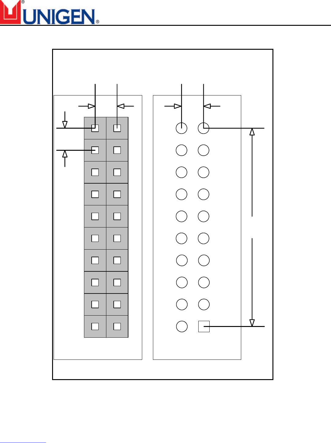
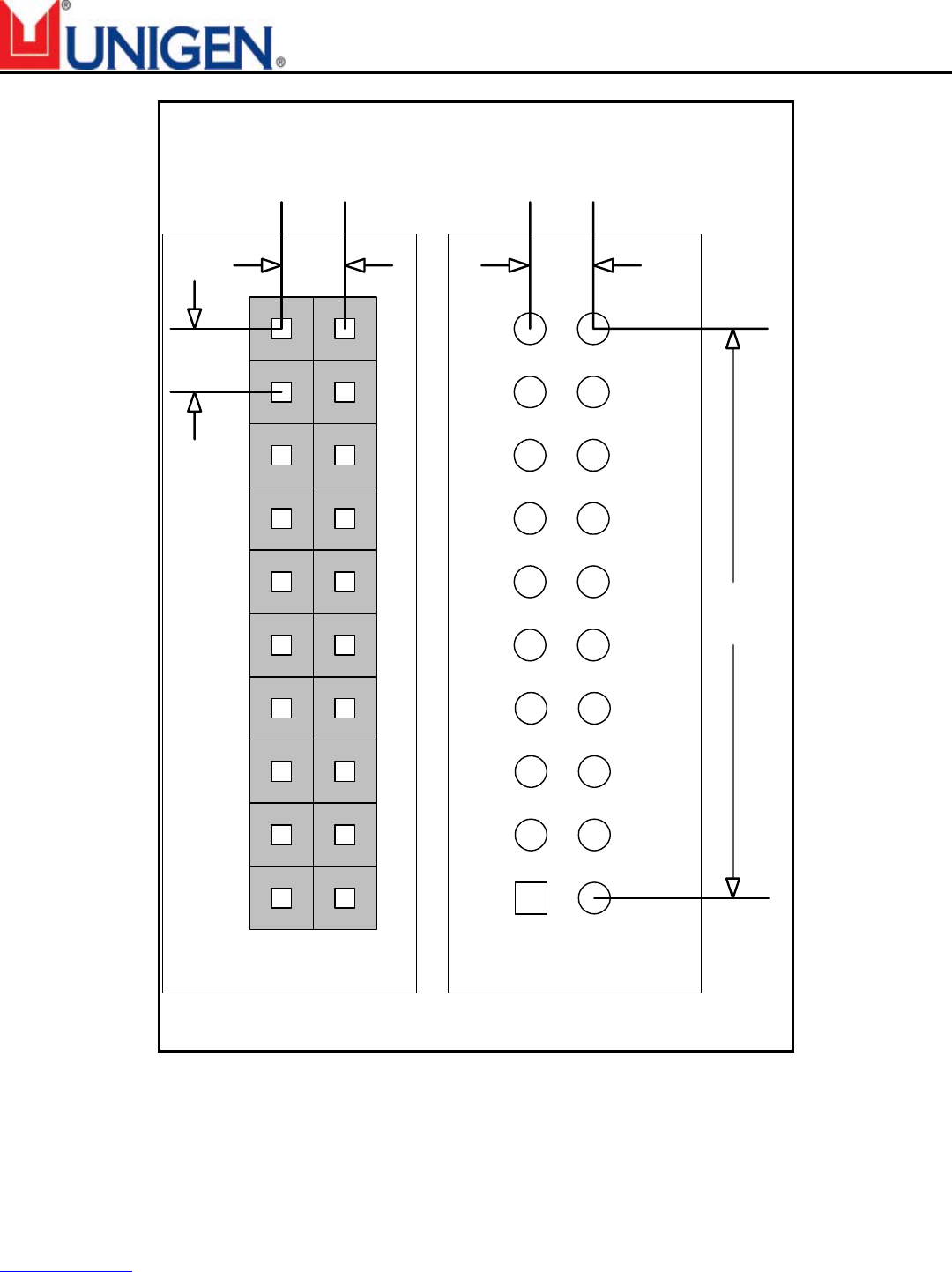
MECHANICAL DRAWINGS:
Juno-LPA
PCB Applications
Land Pattern
Pin 1
2
20
2Pin 1
20
Mated Connnector
PCB Application
.90"
22.86mm
.10"
2.54mm
.10"
2.54mm
Direct PCB
Application
Figure 1 – Juno-LPA Land Pattern
WirelessUSB™ - UGWR2US
Solutions for a Real Time World Data Sheet
Re-Tek - 1236 14 45388 Warm Springs Blvd. Fremont, CA 94539
support@unigen.com TEL: (510) 668.2088 FAX: (510) 661.2788
http://www.unigen.com Toll Free: (800) 826.0808
Copyright Unigen Corporation, 2004
Juno-LPA Mirrored
PCB Applications
Land Pattern
Pin 1 2
20
2Pin 1
20
Mated Connnector
PCB Application
.90"
22.86mm
.10"
2.54mm
.10"
2.54mm
Direct PCB
Application
Figure 2 – Juno-LPA Mirrored Land Pattern
WirelessUSB™ - UGWR2US
Solutions for a Real Time World Data Sheet
Re-Tek - 1236 15 45388 Warm Springs Blvd. Fremont, CA 94539
support@unigen.com TEL: (510) 668.2088 FAX: (510) 661.2788
http://www.unigen.com Toll Free: (800) 826.0808
Copyright Unigen Corporation, 2004
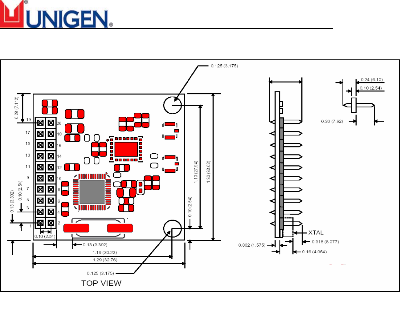
PHYSICAL DIMENSIONS:
Figure 3 – Juno-LPA Dimensions
0.54 (13.716)
WirelessUSB™ - UGWR2US
Solutions for a Real Time World Data Sheet
Re-Tek - 1236 16 45388 Warm Springs Blvd. Fremont, CA 94539
support@unigen.com TEL: (510) 668.2088 FAX: (510) 661.2788
http://www.unigen.com Toll Free: (800) 826.0808
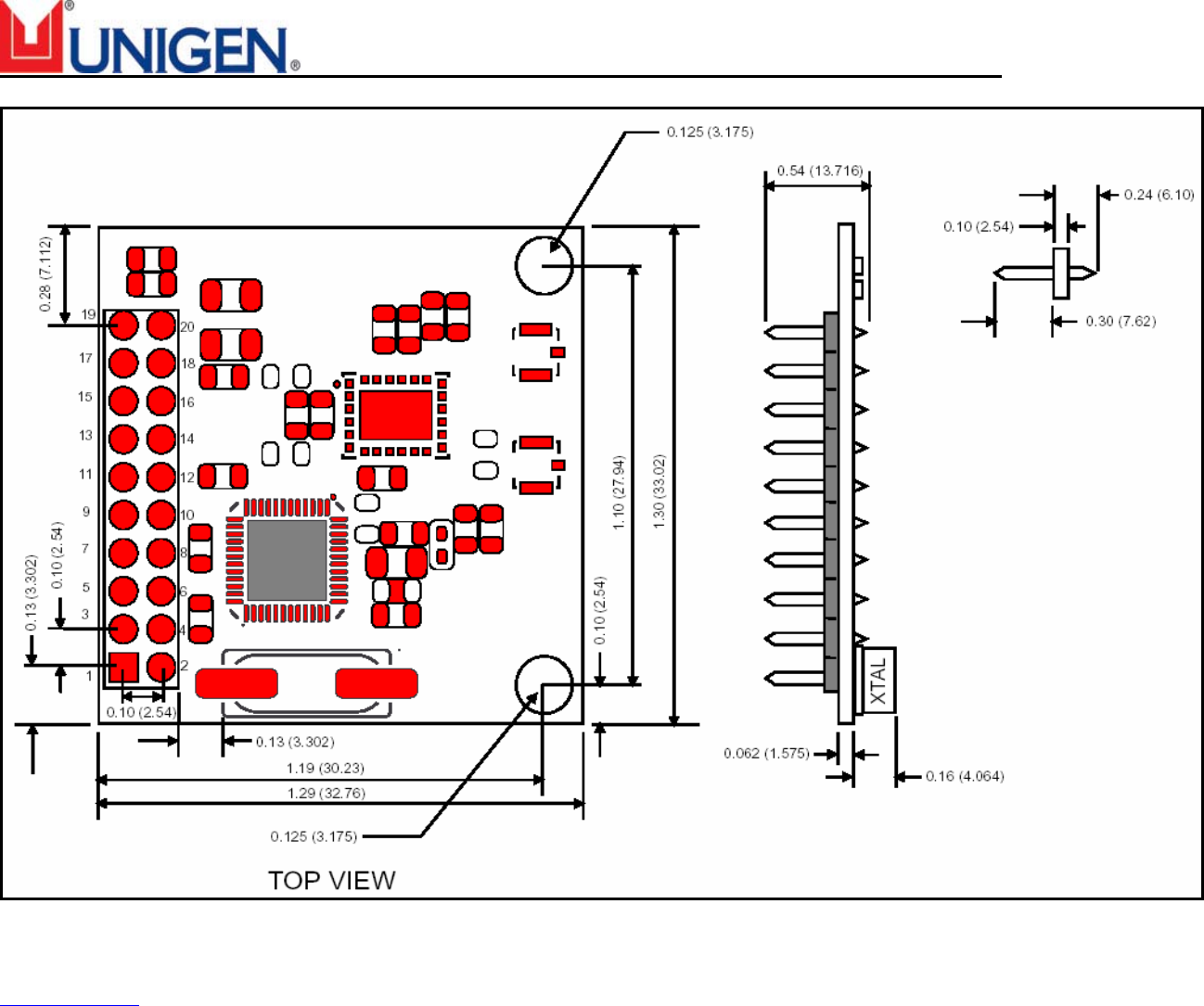
Copyright Unigen Corporation, 2004
Figure 4 – Juno-LPA Mirrored Dimensions
WirelessUSB™ - UGWR2US
Solutions for a Real Time World Data Sheet
Re-Tek - 1236 17 45388 Warm Springs Blvd. Fremont, CA 94539
support@unigen.com TEL: (510) 668.2088 FAX: (510) 661.2788
http://www.unigen.com Toll Free: (800) 826.0808
Copyright Unigen Corporation, 2004
ORDERING INFORMATION:*
JUNO-LPA WirelessUSB™ Module
Unigen
Product Group
– Wireless -
Form Factor WirelessUSB
Tech* Connection Connector Type Voltage
UGW R 2US
HC
HP
BB
2x10 Header
Mirrored 2x10 Header
Bare – No connector
33=3.3Vdc
*Module based on the Cypress Semiconductor CYWUSB6935-48 WirelessUSB™ LR 2.4GHz DSSS Radio SoC device.
Antennae
Unigen
Product Group
– Antennae –
Technology Form Factor
(Appearance)
Frequency /
Gain
Coaxial
Cable Type
Cable
Length
Connector
Type
Special
Requirements
L1=
3.5” desktop
A0=
4” Swivel Whip
B1=
2.4GHz, 2.0dBi
UGA D=
Dipole
Antenna
Module
C1=
7.75” Swivel Whip
B2=
2.4GHz, 5.0dBi
M1=
1.13mm HF
050=
50mm
100=
100mm
150=
150mm
200=
200mm
250=
250mm
300=
300mm
M=
Mini Coax
None=
Default
F=
EMI core and
PVC
Contact your Unigen Sales Representative for additional information or visit the Nexus™ Wireless Products
section of our web site (www.unigen.com).

WirelessUSB™ - UGWR2US
Solutions for a Real Time World Data Sheet
Re-Tek - 1236 18 45388 Warm Springs Blvd. Fremont, CA 94539
support@unigen.com TEL: (510) 668.2088 FAX: (510) 661.2788
http://www.unigen.com Toll Free: (800) 826.0808
Copyright Unigen Corporation, 2004
CONTACT INFORMATION
CORPORATE HEADQUARTERS
Unigen Corporation
45388 Warm Springs Boulevard
Fremont, CA 94539
USA
Telephone: 1.510.688.2088
Fax: 1.510.661.2788
Email: Support@unigen.com
Web: www.unigen.com
Toll Free: 1.800.826.0808