Universal Electronics UNI3 Antenna Receiver User Manual
Universal Electronics, Inc. Antenna Receiver
UserManual.wiki
>
Universal Electronics
>
UNI3 User Manual
user manual
Navigation menu
Upload a User Manual
Namespaces
Wiki Guide
HTML
PDF
Info
Views
User Manual
Discussion / Help
Navigation
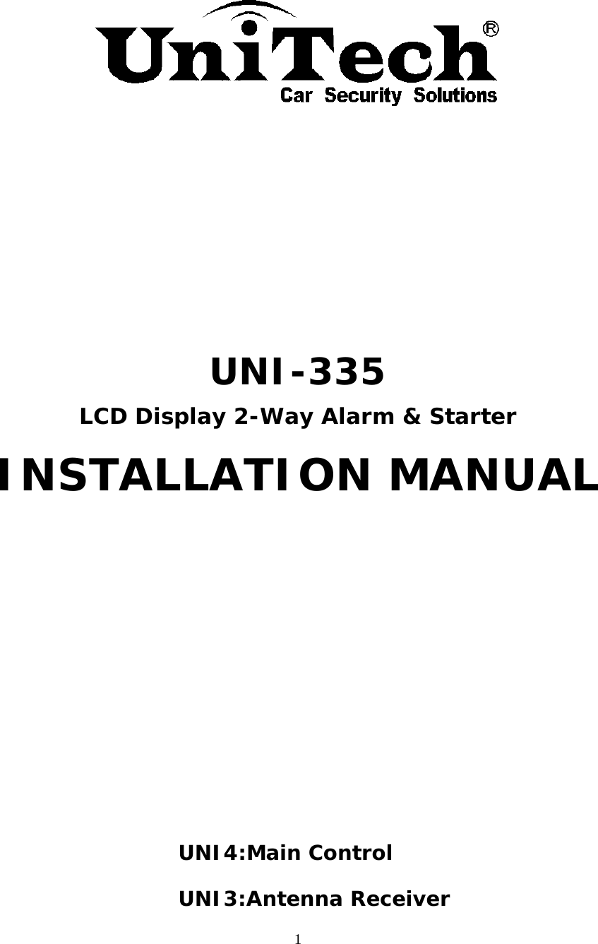
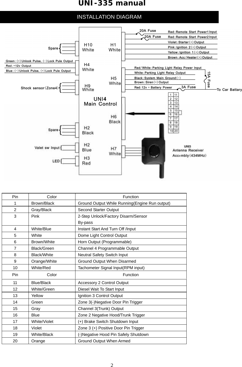
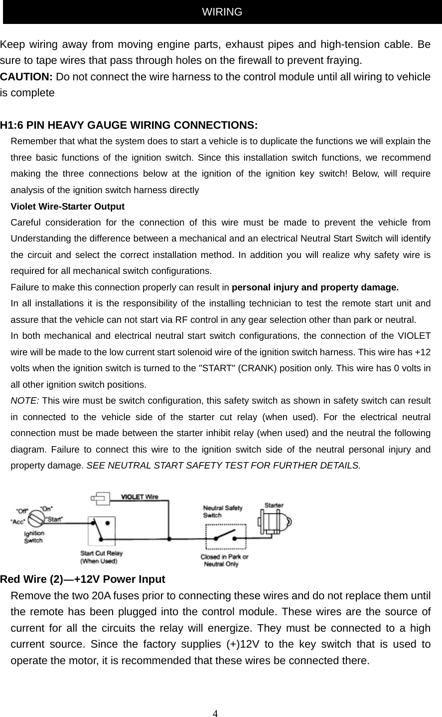
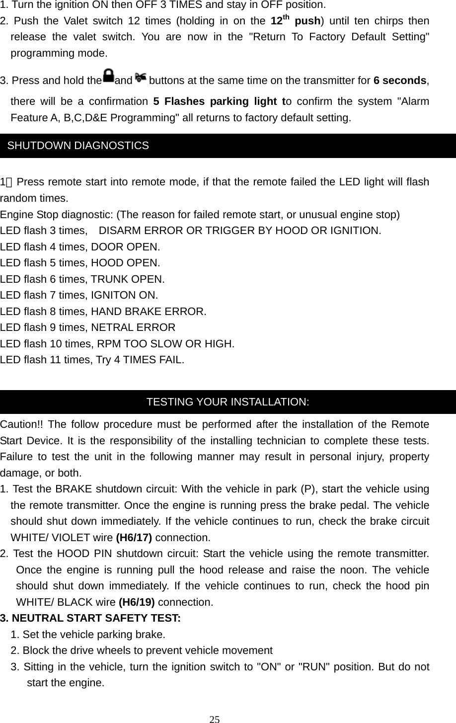
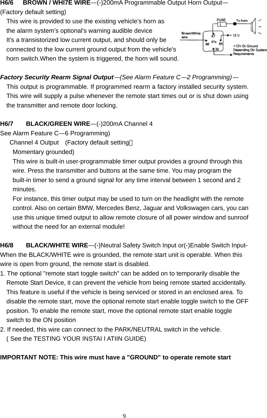
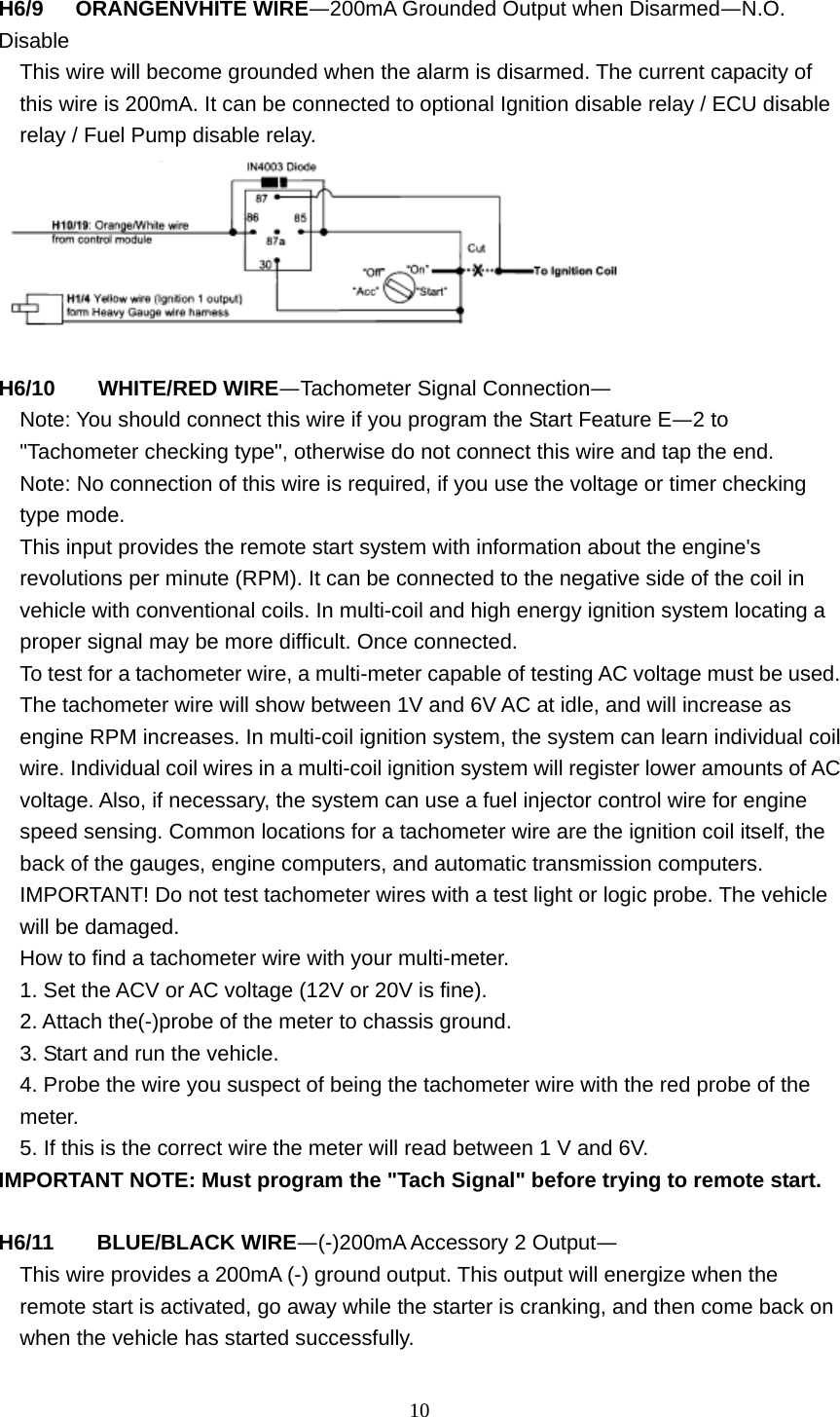
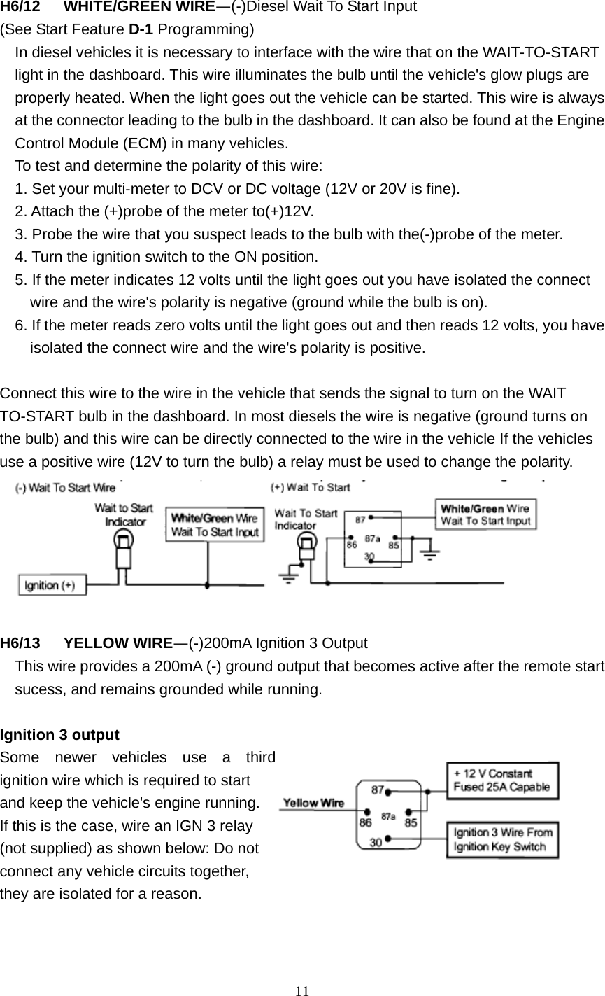
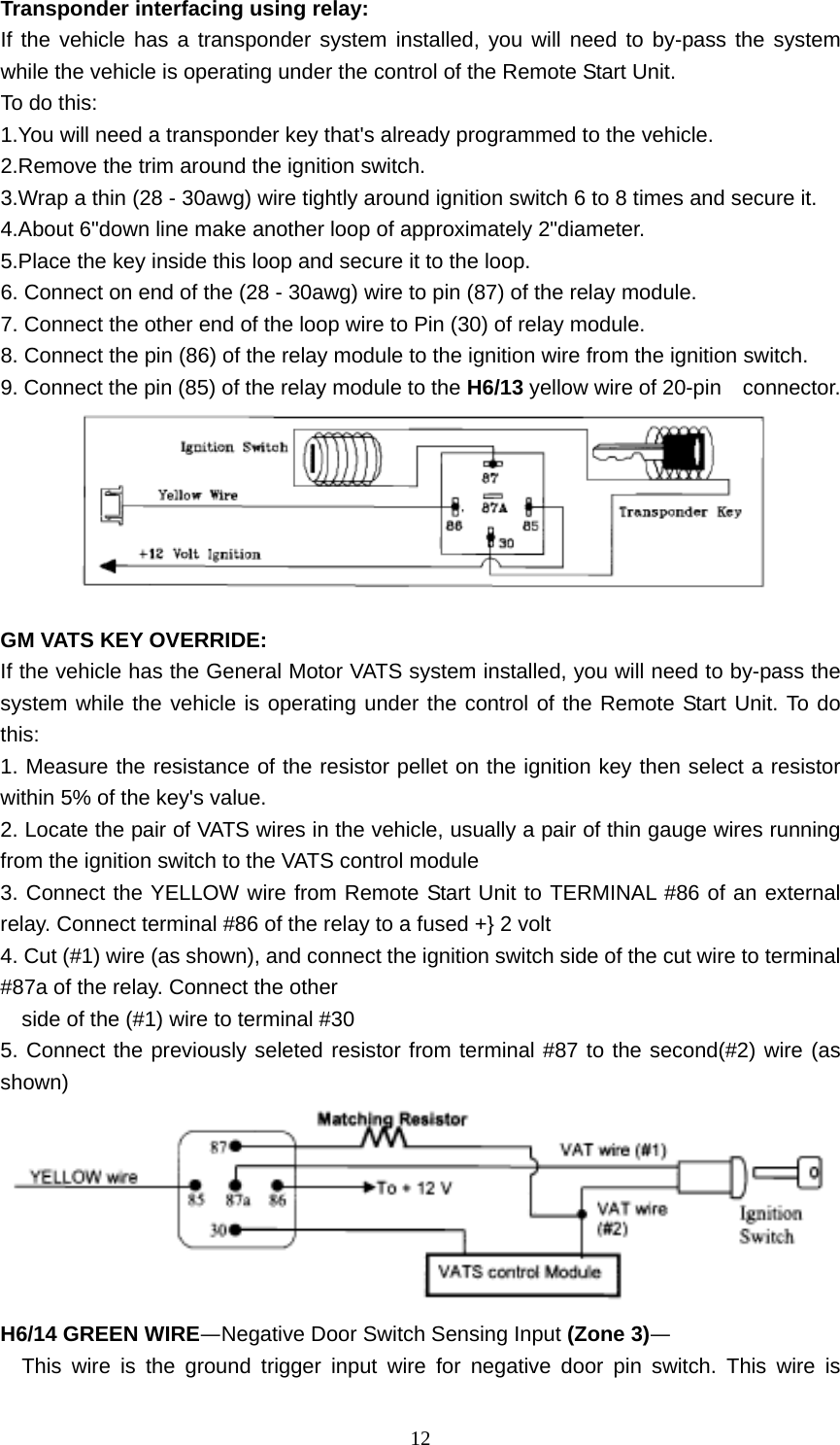
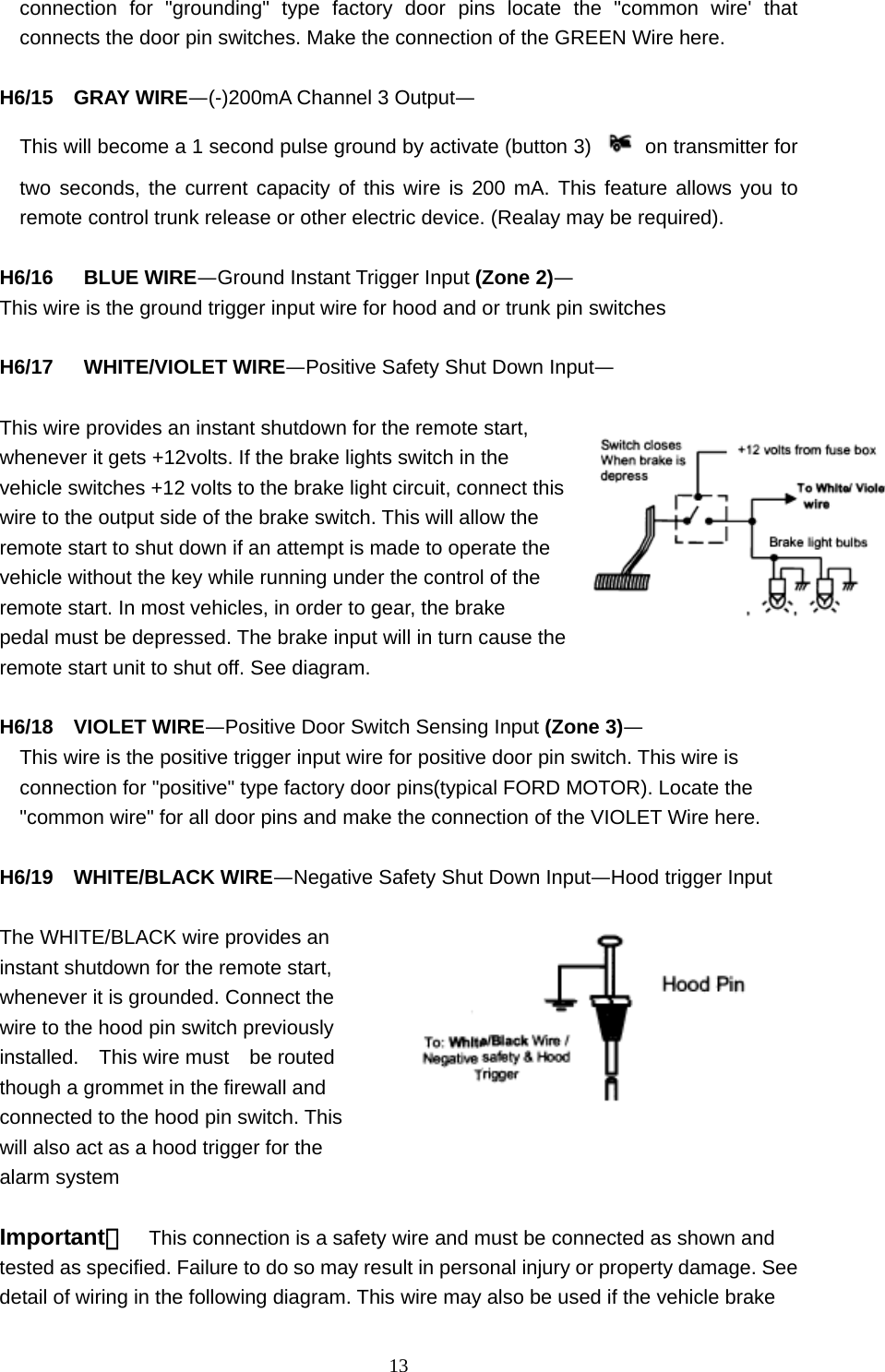
![5 Yellow Wire 一Ignition 1 Output Connect the YELLOW wire to the ignition 1 wire from the ignition switch. The ignition wire should receive “12 volts” when the ignition key is in the "ON" or "RUN" and "START" or "CRANK" position. When the ignition is turned "OFF", the ignition wire should receive "0" voltage. The YELLOW wire must be connected. PINK Wire—Ignition 2 Output Some vehicles have [2] ignition wires that must be power. Connect the PINK wire to the ignition 2 wire from the ignition switch. The ignition wire should receive "12 volts" when the ignition key is in the "ON" or "RUN" and “START" or "CRANK" position. When the ignition is turned "OFF", the ignition wire should receive "0" voltage. If the PINK wire is not used, cap the end of the wire. Brown Wire -Accessory Output (Heater /AC Output) Connect the BROWN wire to the accessory wire in the vehicle that powers the climate control system. An accessory wire will show+12 volts when the ignition switch is turned to the "ACCESSORY" or "ON" and "RUN" positions, and will show 0 Volts when the key is turned to the "OFF" and "START" or "CRANK" position. There will often be more than one accessory wire in the ignition harness. The correct accessory wire will provide power to the vehicle's climate control system. Some vehicles may have separate wires for the blower motor and the air conditioning compressor. In such cases, it will be necessary to add a relay to power the second accessory wire. H5: 5 PIN WIRE HARNESS: RED / WHITE WIRE -PARKING LIGHT RELAY INPUT The RED/WHITE wire is the input to the flashing parking light relay. The connection of the RED/WHITE wire will determine the output polarity of the flashing parking light relay. If the vehicle you are working on has +12volt switched parking lights, you don't need connect this wire. This wire is already connected to +12volt. If the vehicle's parking lights are ground switched, cut the RED/WHITE wire, connect the RED/WHITE wire to chassis ground. WHITE WIRE—PARKING LIGHT RELAY OUTPUT (+12 V 10A OUTPUT) Connect the WHITE wire to the parking light wire coming from the headlight switch. Do not connect the WHITE wire to the dashboard lighting dimmer switch. (Damage to the dimmer will result). The limitation of the WHITE wire is 10 AMP max. Do not exceed this limit or damage to the alarm and parking relay will result. BLACK WIRE—SYSTEM GROUND— This is the main ground connection of the alarm module. Make this connection to a solid section of the vehicle frame.](https://usermanual.wiki/Universal-Electronics/UNI3/User-Guide-1619485-Page-5.png)
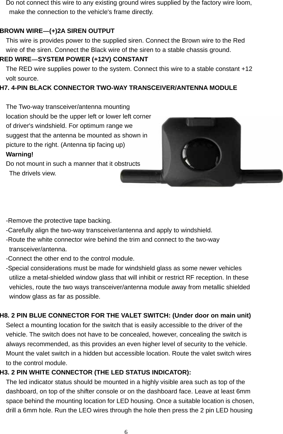
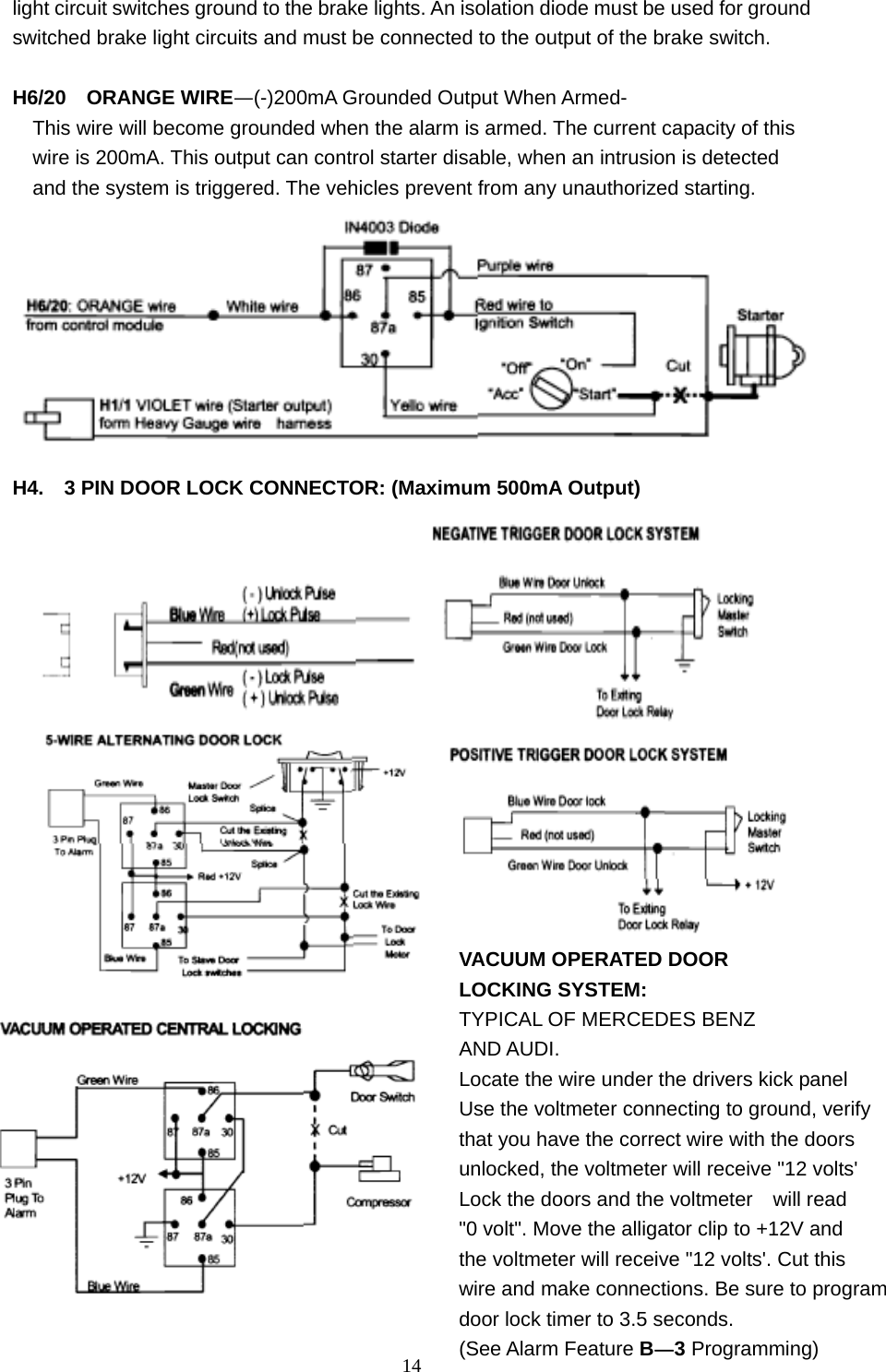
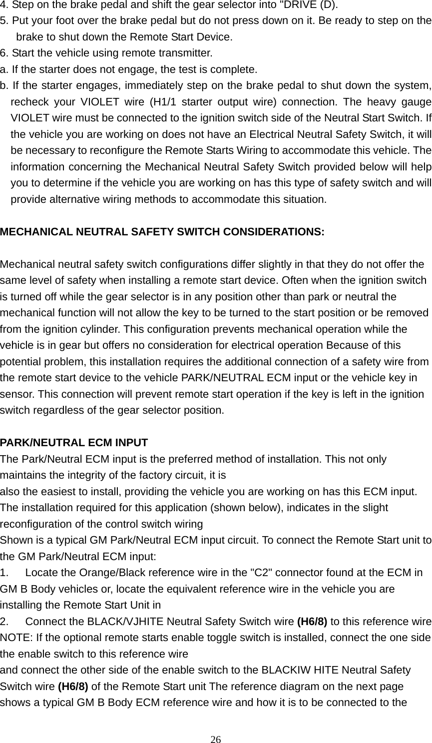
![15 Code learning: Note: This mode will only retain the 4 remote transmitters programmed. If the transmitter memory is exceeded, the security system will start deleting transmitters from memory in chronological order. 1. Turn the Ignition 'switch 'OFF/ON' 3 TIMES and stay in ON position "Within 15 seconds". 2. Push the Valet switch 2 times and hold it on the 2nd push until a long chirp is heard then release the valet switch. You are now in the Transmitter programming mode. 3. Press and hold button1 + button3 of the transmitter until the siren responds with a confirming chirp, indicating the signal has been stored into memory. 4. If you have additional transmitters (up to 4) that need to be programmed, repeat step 3 for each transmitter Exit:Turn Ignition to 'OFF' position, or leave it for 15 seconds. 3 parking light flashes will confirm exit. Featurs Programming: ALARM FEATURE "A" PROGRAMMING: 1. Turn the Ignition 'switch 'ON/OFF' 3 TIMES and stay in OFF position 2. Push the Valet switch 3 times (holding in on the 3rd push) until one chirp & one parking flash. and then release the valet switch. You are now in the Alarm feature "A" programming mode. 3. Press and release the transmitter button corresponding to the feature you want to program. a. The siren chirps and LED pause will indicate previously setting. b. The factory default settings is always [1] LED flash, [1] chirp. 4 Depress the transmitter button to change the feature. Simple keep re-depressing the transmitter button until the system advances to your desired setting. 5. Press the transmitter button corresponding to the feature you want to program. Press Transmitter Button One Chirp/LED one pulseFactory Default Setting Two Chirps/ LED two pulses Three Chirps/ LED three pulses Four Chirps/ LED four pulses 1、 Active arming Passive arming Passive arming without passive door locking Passive arming with passive door locking 2、 Automatic Rearm off Automatic Rearm on 3、 Instant Door Ajar error chirp 45 seconds delay Door Ajarerror chirp. 4、 All Confirmation chirps on Siren Confirmation chirp on only Horn Confirmation chirp on only All Confirmation chirps off PROGRANMMING](https://usermanual.wiki/Universal-Electronics/UNI3/User-Guide-1619485-Page-15.png)
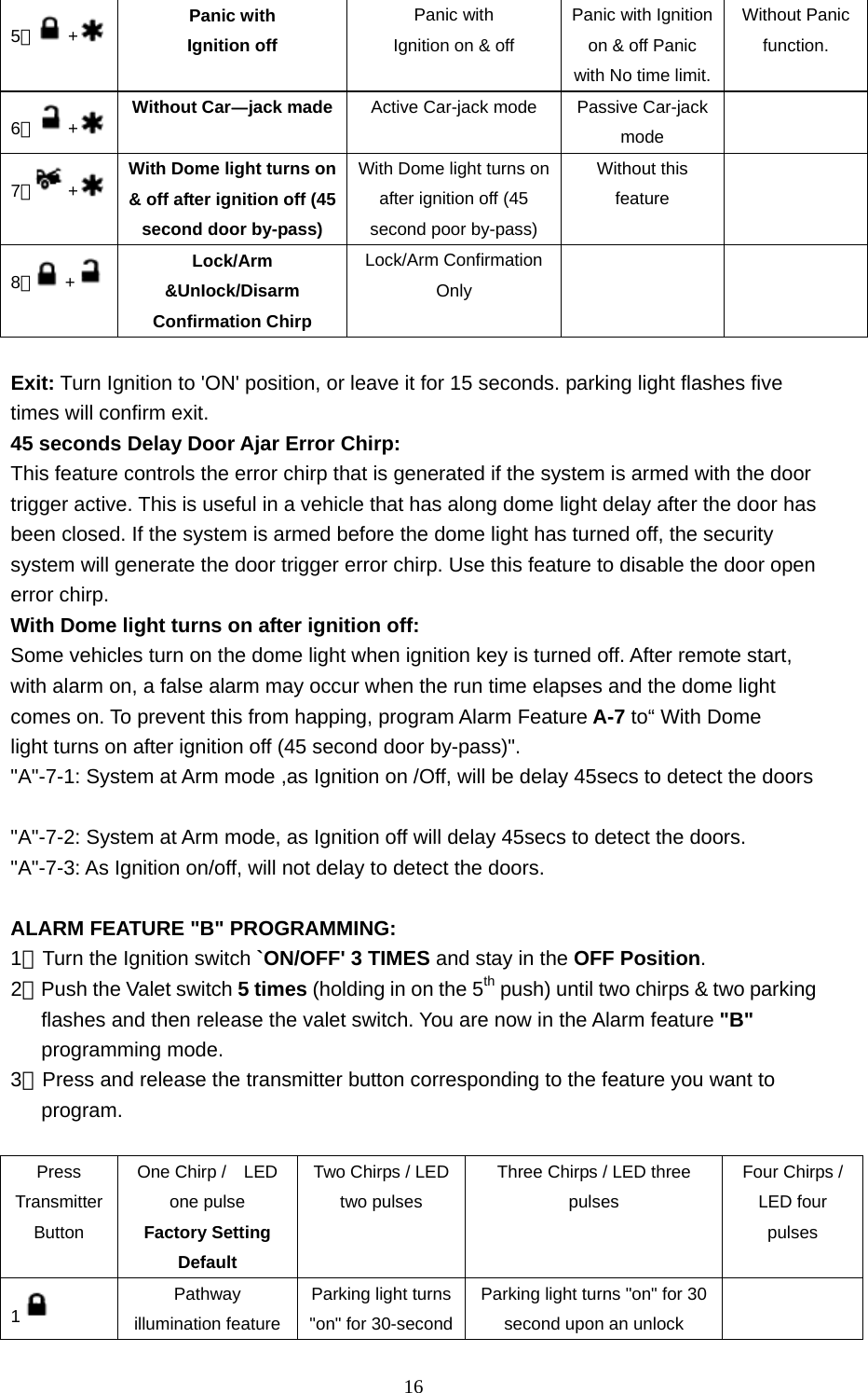
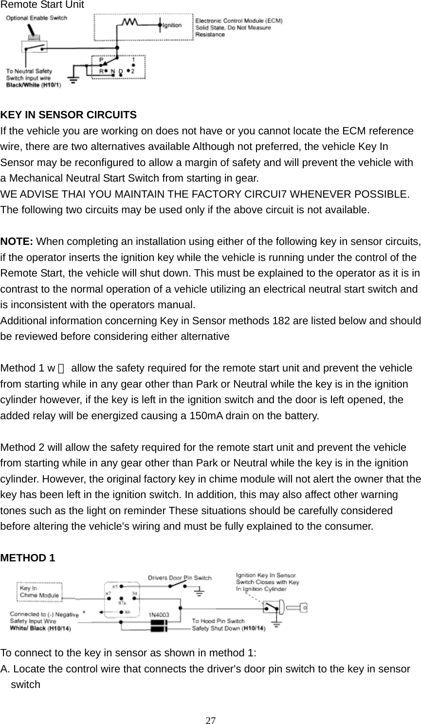
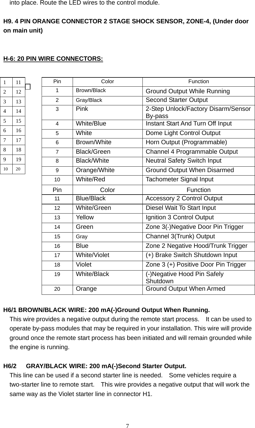
![17“off” upon an unlock signal signal& 10-second upon a lock signal. 2 Ignition controlled door lock & unlock Ignition controlled door locks only Ignition controlled door unlocks only Without ignition controlled door locks & unlocks3 0.8 second door lock & unlock 3.5 second door lock & Unlock 0.8 second Lock 0.35 second Unlock 0.8 second Lock, double 0.8 second. Unlock Five Chirps=Double 0.8 second Lock, 0.8 second Unlock Six Chirps=Door lock with "Comfort Feature” 4 H5/4 Brown Wire=(+) Constant Siren output H5/4 Brown Wire=5-second(+) pulse Siren output H5/4 Brown Wire=(+)Pulsing Output (Relay required for [-] Horn) 5 + 3 Hours Timer Start 2 Hours Timer Start The Vehicle with Turbo (The system Can be Arm with the engine running) The shock sensor will be by-passed upon engine running (The engine will run by itself after the ignition is turned off) The shock sensor by-pass three minutes after armed (The engine will run by itself after the ignition is turned off) Press and buttons at the same time to control Engine run time for one minute and the shock sensor will be by-passed upon engine running 6 + The Vehicle without Turbo Five chirps=Press and buttons at the same time to control Engine run time for three minutes and the shock sensor will be pass upon engine running. Six chirps=Press and buttons at the same time to control Engine run time for five minutes and the shock sensor will he by-passed upon engine running. 7 + Disable the out of range check Enable the out of range check Exit: Turn Ignition to 'ON' position, or leave it for 15 seconds. parking light flashes 5 times will confirm exit](https://usermanual.wiki/Universal-Electronics/UNI3/User-Guide-1619485-Page-17.png)
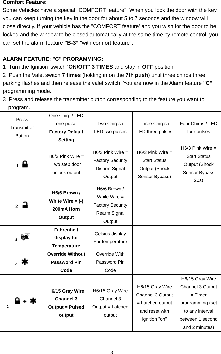
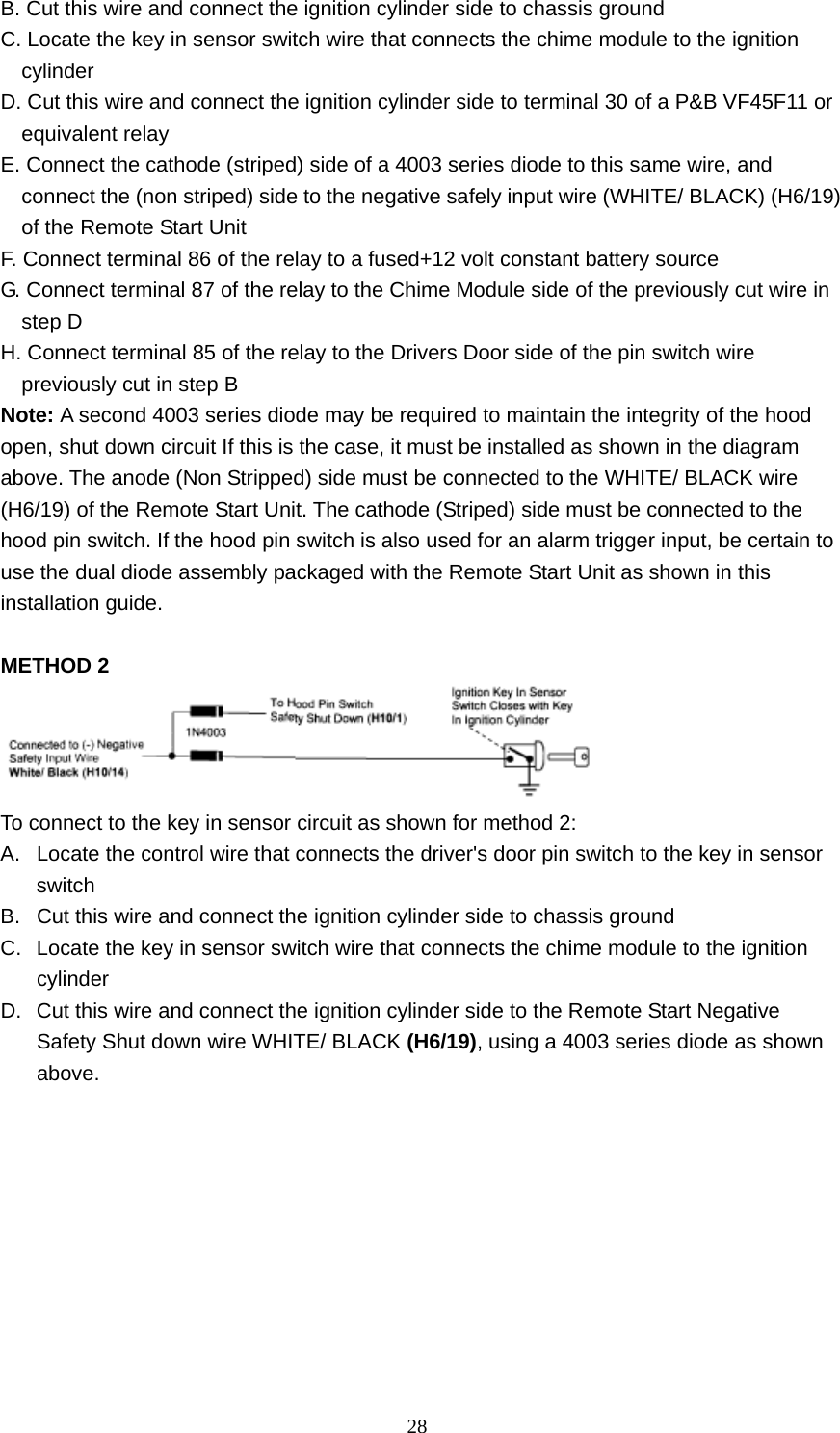
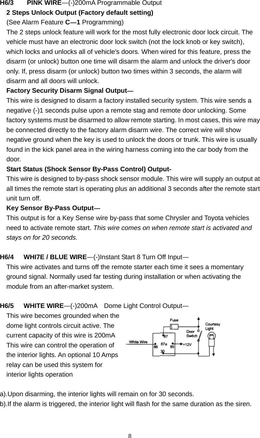
![196 H6/7 Black /Green Wire Channel 4 Output = Momentary outputH6/7 Black / Green Wire Channel 4 Output = Latched outputH6/7 Black / Green Wire Channel 4 Output = Latched output and reset with ignition "on" H6/7 Black / Green Wire Channel 4 Output = Timer programming (set to any interval between 1 second and 2 minutes.) Exit: Turn Ignition to 'ON' position, or leave it for 15 seconds. parking light flashes 5 times will confirm exit. Channel 4 Timer Control Output Programming. Enter: 1. Turn the Ignition 'switch 'ON/OFF' 3 TIMES and stay in OFF position. 2. Push the Valet switch 7 times (holding in on the 7th push) until three chirps three parking flashes then release the valet switch. You are now in the Alarm feature 'C' programming mode. Timer Program: 1. Press and release and buttons together 4 times, [4] LED flash, [4] siren/horn chirps to indicate that you are in features "Channel 4 Timer Programming mode". 2. Press and hold the valet switch, the timer will immediately start. Every 1second ,siren chirp one. 3. When the desired interval has passed, release the valet switch. 1 long chirp for confirmation. (Set to any interval between 1 second and 2 minutes) Note 1: If your built-in timer controls window/sunroof closure in your car DO NOT change the timer setting! This requires installer-only programming. Changing the value will adversely effect operation and may cause damage. Note 2: Momentary output=The momentary output selection will send a negative signal from the Channel 4 output immediately when the channel 4 button is pressed and will continue until the button is released. Latched output=The latched output selection will send a negative signal as soon as the Channel 4 button is pressed and will continue until the button is pressed again Latched output/reset with ignition=The latched/reset with ignition output selection operates just like the latched output but will reset or stop when the ignition is turned on. Enter: 1. Turn the Ignition 'switch 'ON/OFF' 3 times and stay in OFF position. 2. Push the Valet switch 7 times (holding in on 7th push ) until three chirps three parking flashes then release the valet switch. You are now in the Alarm feature "C" the Password Pin Code Setup:](https://usermanual.wiki/Universal-Electronics/UNI3/User-Guide-1619485-Page-19.png)
![20programming mode. You can program or delete the password pin code as below: Program: 1. Press and release the transmitter button twice, [2] LED flash, [2] siren/horn chirp to indicate that you are in features "Password Pin Code Programming mode". 2. Turn on the ignition , within 5 seconds, begin to enter your chosen first 9ths digit by pressing and releasing the valet Switch from 1—9 times. 3. Within 15 seconds , turn the Ignition switch to "OFF" position. 4. Then, Turn on the ignition, Within 15 seconds, enter your chosen second 9ths digit by pressing and releasing the valet Switch from 1—9 times 5. Finish by turning the ignition switch to "OFF” position. If the new password code was accepted, Note: If 15 seconds of inactivity expire, or if the ignition switch is turned "ON" for more then 5 seconds during of above steps, the unit will revert back to the last successfully stored code. 15 seconds later. parking light flashes 5 times will confirm exit. The unit will revert back to the last successfully stored code. Example: To program the Password Code 12, you would(factory default PIN CODE==11); Enter: 1. Turn the Ignition 'switch 'ON/OFF' 3 times and stay in OFF position. 2. Push the Valet switch 7 times (holding in on the 7th push) it until three chirps& three parking flashes , and then release the valet switch. You are now in the Alarm feature "C" programming mode. Program: 1. Press and release the transmitter button twice, [2] LED flash, [2] siren/horn chirp to indicate your are in features“Password pin code programming mode". 2. turn on ignition,Within 5 seconds, press and release the valet Switch 1 times. 3. Within 15 seconds, turn the Ignition Switch to "Off" position 4. Then turn Ignition Switch to "On" , Within 15 seconds press the valet Switch 2 times. 5. Turn the Ignition Switch to "OFF' position. You will note PIN CODE 12 on FF282 flash, and stored in memory. Exit: wait it for 15 seconds. parking light flashes 5 times will confirm exit. START FEATURE "D" PROGRAMMING: 1. Turn the Ignition 'switch 'ONIOFF' 3 TIMES and stay in OFF position. 2. Push the Valet switch 9 times (holding in on the 9th push) until four chirps &three parking flashes then release the valet switch. You are now in the Start feature "D" REMOTE START FEATURE PROGRAM MODE.](https://usermanual.wiki/Universal-Electronics/UNI3/User-Guide-1619485-Page-20.png)
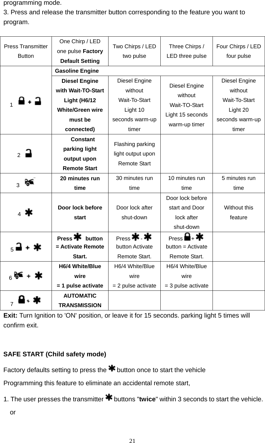
![222. The user presses the transmitter and buttons at the "same time" to start the vehicle. START FEATURE: "E" PROGRAMMING: 1. Turn the lgnition 'switch 'ON/OFF' 3 TIMES and stay in OFF position. 2. Push the Valet switch 11times (holding in on the 11th push) until five chirps &five parking flashes then release the valet switch. You are now in the Start feature "E" programming mode. 3. Press and release the transmitter button corresponding to the feature you want to Press Transmitter Button One Chirp / LED one pulse Factory Default Setting Two Chirps/ LED two pulse Three Chirps/ LED three pulse Four Chirps/ LED four pulse 1 Exit the programming mode. (5 parking light flashes to confirm this exit) 2 Tachometer Check type (3A) Voltage check type (go to 3B) Timer checking type (go to 3B) A>RPM learning-see RPM Learning page 20 3 B> Start Crank Time: 0.8-second 1.2-second (2 chirps), 1.6-second (3 chirps), 2.0-second (4 chirps), 3.0-second (5 chinos). 4.0-second (6 chinos). 4 TESTING exit 5 "TEST" Mode for Zone 2 / instant trigger & Zone 3 / Door trigger TEST" Mode for Zone 1&Zone 4 (2 Stage Shock Sensor) Exit: Press the button on the transmitter. Parking light flashes 5 times will confirm exit. The control module learning RPM method has 2 types. One type of method: [Engine speed (RPM) Learning process] As engine running detection, select TACH meter Impulse, and it needs to complete engine speed (RPM) learning process. After completed engine speed (RPM) learning process. *Each time the system start engine, as successfully detect engine running, start switch will immediately close, it does not need to reach the maxim 4 seconds. Attention! It needs special engine speed (RPM) learning process before installation. <1>Red line, connect to +12V. <2>Black line , connect to GND. <3>White/Red wire connection. (H6/10) line; connect to TACH meter Impulse (ignition PRM LEARNNING/TACHOMETER CHECKING TYPE](https://usermanual.wiki/Universal-Electronics/UNI3/User-Guide-1619485-Page-22.png)
![23signal). <4>Start engine with key, LED will fast flash when the lines are properly connected <5>Shut down the engine when the engine speed to stabilize. <6>when use UNI2 or remote control module will auto exit the learning mode. <7> To re-learn the engine speed (RPM), it can learn again after Disarm the host power and then send power. <8> RPM can’t not learn if foot brake. 2nd type of method: 1.Turn the Ignition switch 'ON/OFF' 3 TIMES and stay in OFF position. 2.Push the Valet switch 11 times and hold it on the 11th push until five chirps &five parking flashes then release the valet switch. 3. Press and release the transmitter and buttons at the same time once to set the "Tachometer Checking Type'. [1] LED flash, [1] chirp to confirm this setting. 4. Press and release the transmitter button once, [1] LED flash, [1] chirp to indicate your are in features "RPM Learning mode" 5. Start the vehicle with the key. (While the engine is running, the parking&LED will flash, If don't, please check tachometer White/Red wire connection. (H6/10) Press the valet switch, the siren will chirp one long sound then exit the learning mode. 6. Turns off the ignition switch to stop the engine running. ============================= Remote Start Function ============================= [Remote Start Operation] The control module should be under the arm status then can be remote. *press Button 4(once),can start engine by remote. *button 4(2 seconds) to cancel engine start program; engine operation can be stopped if running. Engine start is fixed to 4 times: First time: 0.8~3.0 seconds.(function setting) Second time: automatically plus 0.2seconds. Third time: automatically plus 0.2seconds. Fourth time : automatically plus 0.2seconds. * If the engine does not start successfully, the system will automatically re-start, a total of 4 times, ignition set by function, it will plus 0.2seconds every time. After the successful operation of the ignition detection of 7 second period, Ignition off/on re-start interval 5seconds.(a total of 13 seconds) * Start the engine 4 times without success, it will stop and start. * Remote start the engine, and engine running, the security must first disarm, open car door, Insert the key and rotate to ON,and can start the car. *After start the engine by remote in engine running, setting arm Ignition and sensor](https://usermanual.wiki/Universal-Electronics/UNI3/User-Guide-1619485-Page-23.png)
![24vibration sensor does not detect automatically. Note: Attention! start the engine by remote, the system must be arm status base on security. In this test made, this system can test the Zone 2 (Instant ground trigger), the Zone 3 (Door trigger), and the Zone1&Zone 4 (2 stage shock sensor) sensitivity. The installer can save time to test the 2-stage shock sensor sensitivity and sensor without usingthe traditional arming/disarming procedures to test the sensors. Enter 1. Turn the Ignition 'switch 'ON/OFF' 3 TIMES and stay in OFF position. 2. Push the Valet switch 11 times (holding in on the 11th) until five chirps &five parking flashes then release the valet switch.You are now in the Start feature "E" programming mode. a. Test the Zone 2 / Instant Ground Trigger 8 Zone3 / Door Trigger: Press and release the transmitter and buttons at the same time once. [1] LED flash, [1] siren/horn chirp to indicate your are in Zone 2/instant Around trigger and Zone 3/Door trigger test mode. Trigger sensor Siren chirps Zone 2/Instant Ground trigger (H6/16 Blue wire) 2 Zone 3/Door trigger (H6/14 Green or H6/1R Violet wire) 3 b. Test the Zone 1&Zone 4 / Two Stage Shock Sensor (Connected to H9 4 Pin Plug): Press and release the transmitter and buttons at the same time again. [2] LED flash, [2] siren/horn chirps to indicate you are in the shock sensor (connected to H9 4 pin plug) test mode. 1. Activate the warn-away (ffirst stage of the shock sensor / Zone 1) ,system will emit a short chirp. 2. Activate the full alarm (second stage of the shock sensor/Zone 4), system will emit a long chirp. Press the button on the transmitter. Siren chirp 1 times will confirm test mode exit. Press the button on the transmitter. parking light flashes 5 times will confirm exit. TEST MODE RETURN TO FACTORY DEFAULT SETTING:](https://usermanual.wiki/Universal-Electronics/UNI3/User-Guide-1619485-Page-24.png)