Universal Scientific UGNAS-P3 NETWORK ATTACHED STORAGE User Manual User guide for P2 V1 1 01 28
Universal Scientific Industrial Co., Ltd. NETWORK ATTACHED STORAGE User guide for P2 V1 1 01 28
USERS MANUAL

1
Topkick1281P2 User Guide
Version 1.1
1. Firmware Images Layout
T
he u-boot image is about 512KB and located in the NAND or SPI flash between 0 and
0x0100000, be careful to erase it when update new u-boot. And layout of firmware images on
NAND flash is as follows
Note: Please DO NOT erase the UBoot space if it is not necessary
eziStesffOegamI
000001x00x0toob-U
00002x0000081x0tnemnorivnetoob-U
000006x0000002x0lenreK
0000001x0000008x0)drtinI(metsyseliF
Table 1-1: Firmware NAND Flash Layout
2. Network Service
The eth0 static IP is 192.168.58.100. The wireless AP’s static IP is 192.168.1.1. The AP’s SSID
is Topkick1281P2-AP-* and it has no encryption.
The default network services on the board are Samba, FTP and Telnet.
Username and password for Samba and Telnet’s are root:root.
Username and password for Ftp is admin:admin.
3. How to Boot From SATA Disk
The default u-boot bootcmd is “bootcmd=nand read.e 0x1200000 0x200000 0x600000;nand
read.e 0x2000000 0x800000 0x1000000;bootm 0x1200000 0x2000000” and the bootargs valuable
is “bootargs=console=ttyS0,115200”
If you want to port the root filesystem to sata disk partition please type the command below
in U-boot environment, which can be modified on your demand.
Marvell>> setenv bootargs 'console=ttyS0,115200 root=/dev/sda1 rw'
Marvell>> setenv bootcmd 'nand read.e 0x1200000 0x200000 0x600000;bootm 0x1200000'
Marvell>> save
Marvell>> boot
4. How to Boot From USB Disk
The default u-boot bootcmd is “bootcmd=nand read.e 0x1200000 0x200000 0x600000;nand
read.e 0x2000000 0x800000 0x1000000;bootm 0x1200000 0x2000000” and the bootargs valuable
is “bootargs=console=ttyS0,115200”
If you want to port the root filesystem to USB disk partition please type the command below
in U-boot environment, which can be modified on your demand.
Marvell>> setenv bootargs 'console=ttyS0,115200 root=/dev/sda1 rw rootdelay=10'
//Note: root=/dev/sda1 can be changed to root=/dev/sdb1 or others according to USB partition name
Marvell>> setenv bootcmd 'nand read.e 0x1200000 0x200000 0x600000;bootm 0x1200000'
Marvell>> save
Marvell>> boot
N
etwork-Attached Storage User Guide
is Network-Attached Storage-AP-* and it has no encryption.

2
5. Programmable Function
5.1 Switch Function
The switch action is detected by the daemon “pwrctl –d”. The switch has two directions. You
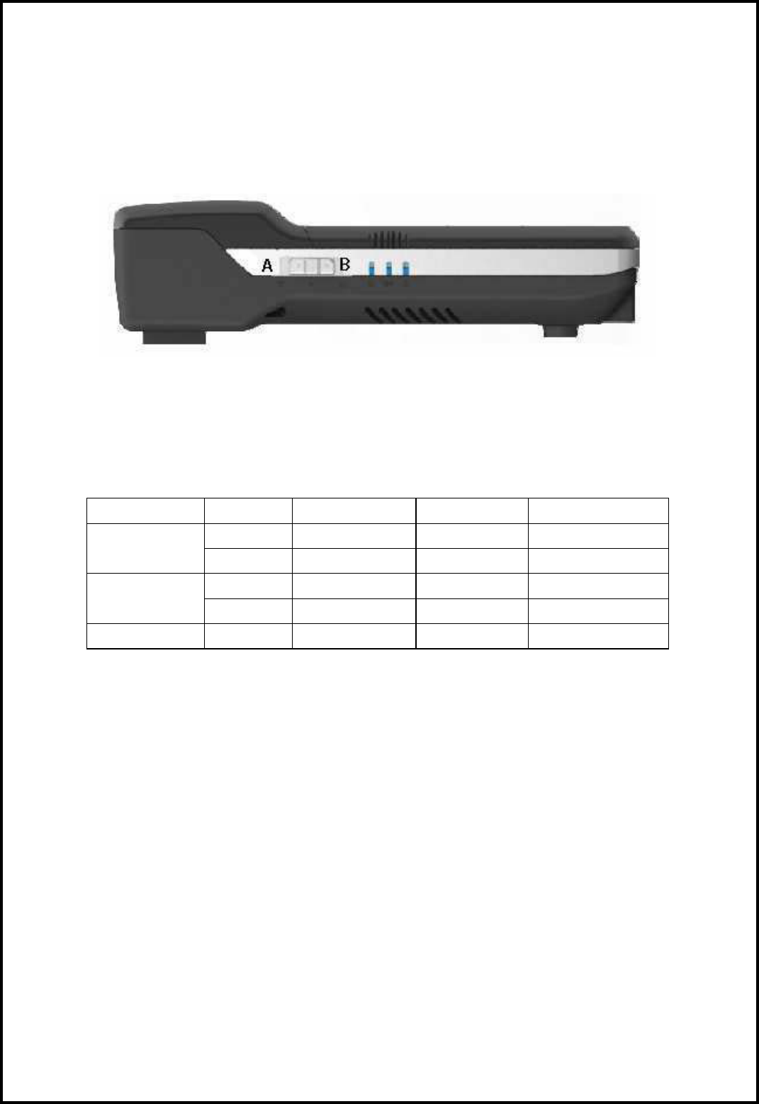
can switch button to position A to shut down the system by script /usr/sbin/switch_off (t>2S), switch
to position B to excute /usr/sbin/switch_optional which can be customized. See Figure 1-1
Figure 1-1: Topkick1281P2 Switch Indication
5.2 Led Control Function
The board has five LEDs and their control commands and functions are as Table 1-1:
LED Function Led Color Light On Light Off Blink
Blue pwrctl -o 502 pwrctl -o 503 pwrctl -o 504
System LED Red pwrctl -o 602 pwrctl -o 603 pwrctl -o 604
Yellow pwrctl -o 302 pwrctl -o 303 pwrctl -o 304
Wireless LED Green pwrctl -o 702 pwrctl -o 703 pwrctl -o 704
SATA LED Blue None None None
Table 2-1: LED Control Function Table
5.3 WOL Function
The topkick1281p2 system support WOL(Wake On Lan) function. The magic packet can be
sent by magic packet tool such as magpac.exe to turn on the system if the system is powered and
connect to network.
5.4 WiFi Function
The WiFi controller IC is sd8786 which work in AP mode. The file sd8786_uapsta.bin should
be copied to /lib/firmware/mrvl/ directory. The operations to load the driver module, configure and
bring up the wifi interface are as follows.
/ # insmod /lib/modules/mlan.ko
/ # insmod /lib/modules/sd8xxx.ko
/ # uaputl.exe sys_cfg_ssid $APNAME
/ # uaputl.exe bss_start
/ # ifconfig uap0 192.168.1.1
“uaputl.exe --help” for more details.
Network-Attached Storage Switch Indication
Network-Attached Storage

3
FCC Regulations:
15.19(a)(3):
This device complies with part 15 of the FCC Rules. Operation is subject to the
following two conditions: (1) This device may not cause harmful interference, and (2)
this device must accept any interference received, including interference that may
cause undesired operation.
15.105(b):
NOTE: This equipment has been tested and found to comply with the limits for a
Class B digital device, pursuant to part 15 of the FCC Rules. These limits are
designed to provide reasonable protection against harmful interference in a
residential installation.
This equipment generates, uses and can radiate radio frequency energy and, if not
installed and used in accordance with the instructions, may cause harmful
interference to radio communications. However, there is no guarantee that
interference will not occur in a particular installation. If this equipment does cause
harmful interference to radio or television reception, which can be determined by
turning the equipment off and on, the user is encouraged to try to correct the
interference by one or more of the following
measures:
—Reorient or relocate the receiving antenna.
—Increase the separation between the equipment and receiver.
—Connect the equipment into an outlet on a circuit different from that to which the
receiver is connected.
—Consult the dealer or an experienced radio/ TV technician for help.
Changes or modifications not expressly approved by the party responsible for
compliance could void the user‘s authority to operate the equipment.
zThe antenna(s) used for this transmitter must not be co-located or operating in
conjunction with any other antenna or transmitter.
RF Exposure Information
This device meets the government’s requirements for exposure to radio waves.
This device is designed and manufactured not to exceed the emission limits for
exposure to radio frequency (RF) energy set by the Federal Communications
Commission of the U.S. Government.
zThis device complies with FCC radiation exposure limits set forth for an uncontrolled
environment. In order to avoid the possibility of exceeding the FCC radio frequency
exposure limits, human proximity to the antenna shall not be less than 20cm (8 inches)
during normal operation.