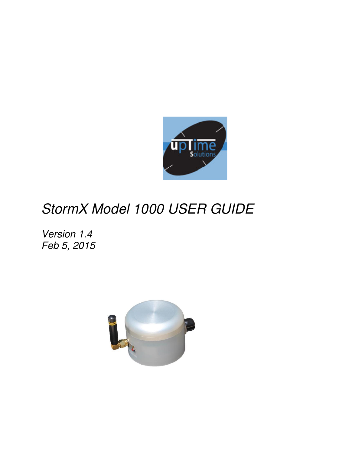
Uptime Solutions BA1000 900 MHz FHSS Transceiver User Manual
Uptime Solutions 900 MHz FHSS Transceiver
UserManual.wiki
>
Uptime Solutions
>
BA1000 User Manual
User Manual
Navigation menu
Upload a User Manual
Namespaces
Wiki Guide
HTML
PDF
Info
Views
User Manual
Discussion / Help
Navigation
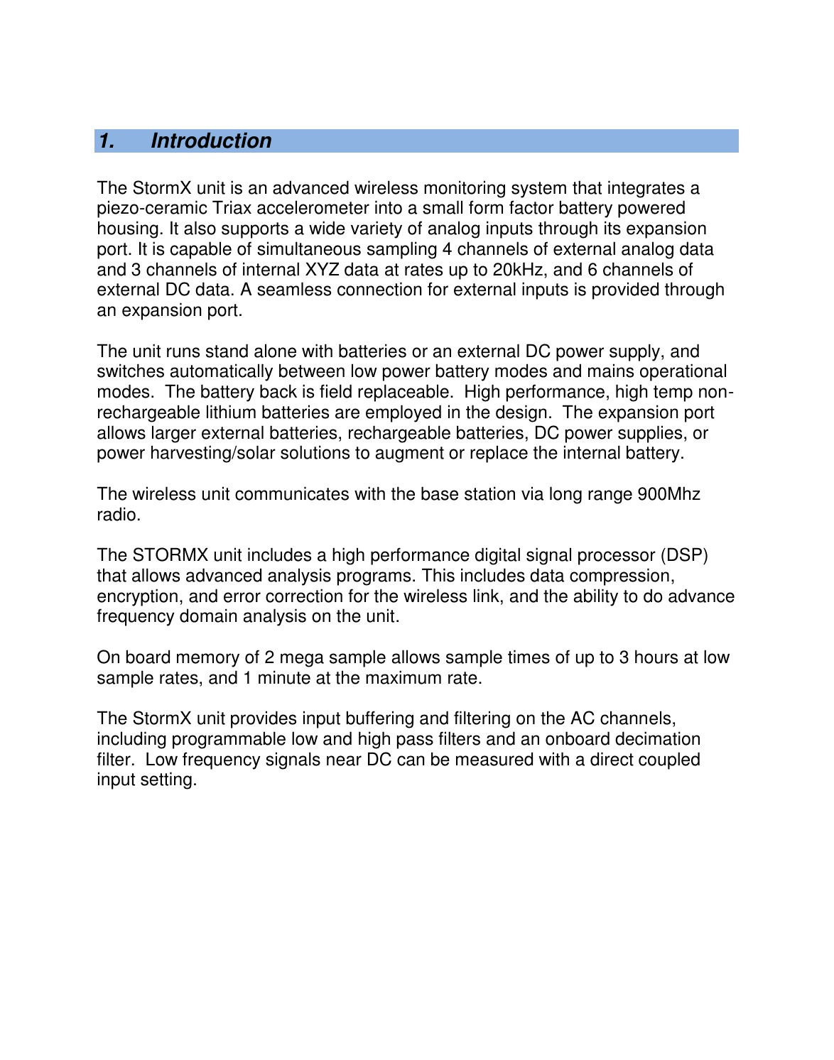
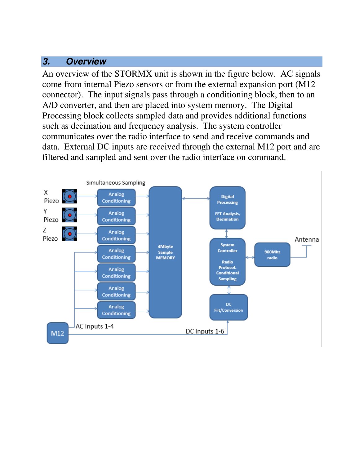
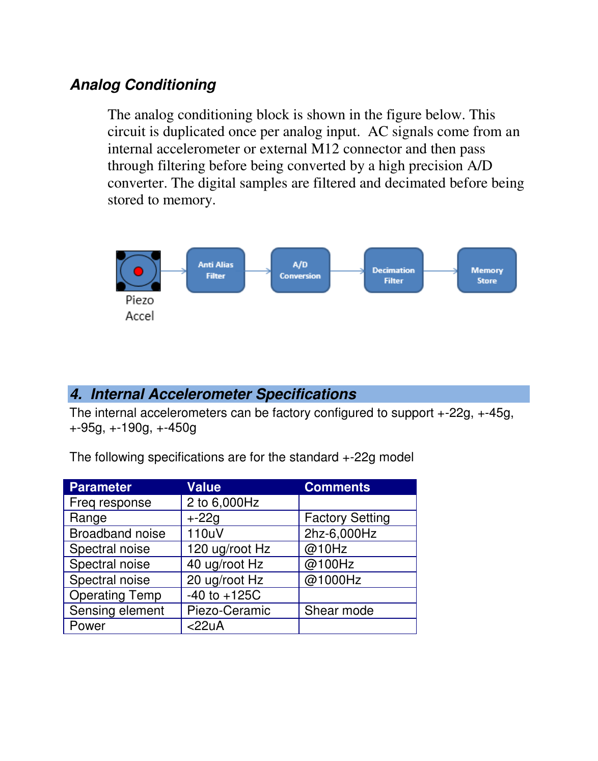
![2. Key Features StormX has the following features: 3 Internal acceleration channels, XYZ direction. High accuracy PiezoElectric triaxial accelerometer Support for 4 external analog AC inputs through an expansion port [future product]. Support for 6 external DC/process inputs through an expansion port [future product]. Simultaneous sampling of 3 internal acceleration channels and 4 external channels at rates of 64Hz up to 20kHz. Onboard decimation filter and alias filter. Long range wireless connectivity using a high powered advanced 900MHz radio. Ranges of up to 2 miles in outdoor environments. On board sample memory allowing 2 million samples at sample rates from 64Hz to 20kHz. On board digital processing for advanced functions (spectrum analysis, alarms). [Requires user customization]. Water and weatherproof durable casing sealed to IP67 standards and including standard M12 connector for expansion port. Anti caustic casing made from stainless and resistant plastics. Battery or mains operation. High temp design target of 185F.](https://usermanual.wiki/Uptime-Solutions/BA1000/User-Guide-2540170-Page-3.png)