Uptime Solutions BA1000 900 MHz FHSS Transceiver User Manual
Uptime Solutions 900 MHz FHSS Transceiver
User Manual
StormX Model 1000 USER GUIDE
Version 1.4
Feb 5, 2015

1. Introduction
The StormX unit is an advanced wireless monitoring system that integrates a
piezo-ceramic Triax accelerometer into a small form factor battery powered
housing. It also supports a wide variety of analog inputs through its expansion
port. It is capable of simultaneous sampling 4 channels of external analog data
and 3 channels of internal XYZ data at rates up to 20kHz, and 6 channels of
external DC data. A seamless connection for external inputs is provided through
an expansion port.
The unit runs stand alone with batteries or an external DC power supply, and
switches automatically between low power battery modes and mains operational
modes. The battery back is field replaceable. High performance, high temp non-
rechargeable lithium batteries are employed in the design. The expansion port
allows larger external batteries, rechargeable batteries, DC power supplies, or
power harvesting/solar solutions to augment or replace the internal battery.
The wireless unit communicates with the base station via long range 900Mhz
radio.
The STORMX unit includes a high performance digital signal processor (DSP)
that allows advanced analysis programs. This includes data compression,
encryption, and error correction for the wireless link, and the ability to do advance
frequency domain analysis on the unit.
On board memory of 2 mega sample allows sample times of up to 3 hours at low
sample rates, and 1 minute at the maximum rate.
The StormX unit provides input buffering and filtering on the AC channels,
including programmable low and high pass filters and an onboard decimation
filter. Low frequency signals near DC can be measured with a direct coupled
input setting.

2. Key Features
StormX has the following features:
3 Internal acceleration channels, XYZ direction.
High accuracy PiezoElectric triaxial accelerometer
Support for 4 external analog AC inputs through an
expansion port [future product].
Support for 6 external DC/process inputs through an
expansion port [future product].
Simultaneous sampling of 3 internal acceleration channels
and 4 external channels at rates of 64Hz up to 20kHz.
Onboard decimation filter and alias filter.
Long range wireless connectivity using a high powered
advanced 900MHz radio. Ranges of up to 2 miles in
outdoor environments.
On board sample memory allowing 2 million samples at
sample rates from 64Hz to 20kHz.
On board digital processing for advanced functions
(spectrum analysis, alarms). [Requires user customization].
Water and weatherproof durable casing sealed to IP67
standards and including standard M12 connector for
expansion port.
Anti caustic casing made from stainless and resistant
plastics.
Battery or mains operation.
High temp design target of 185F.
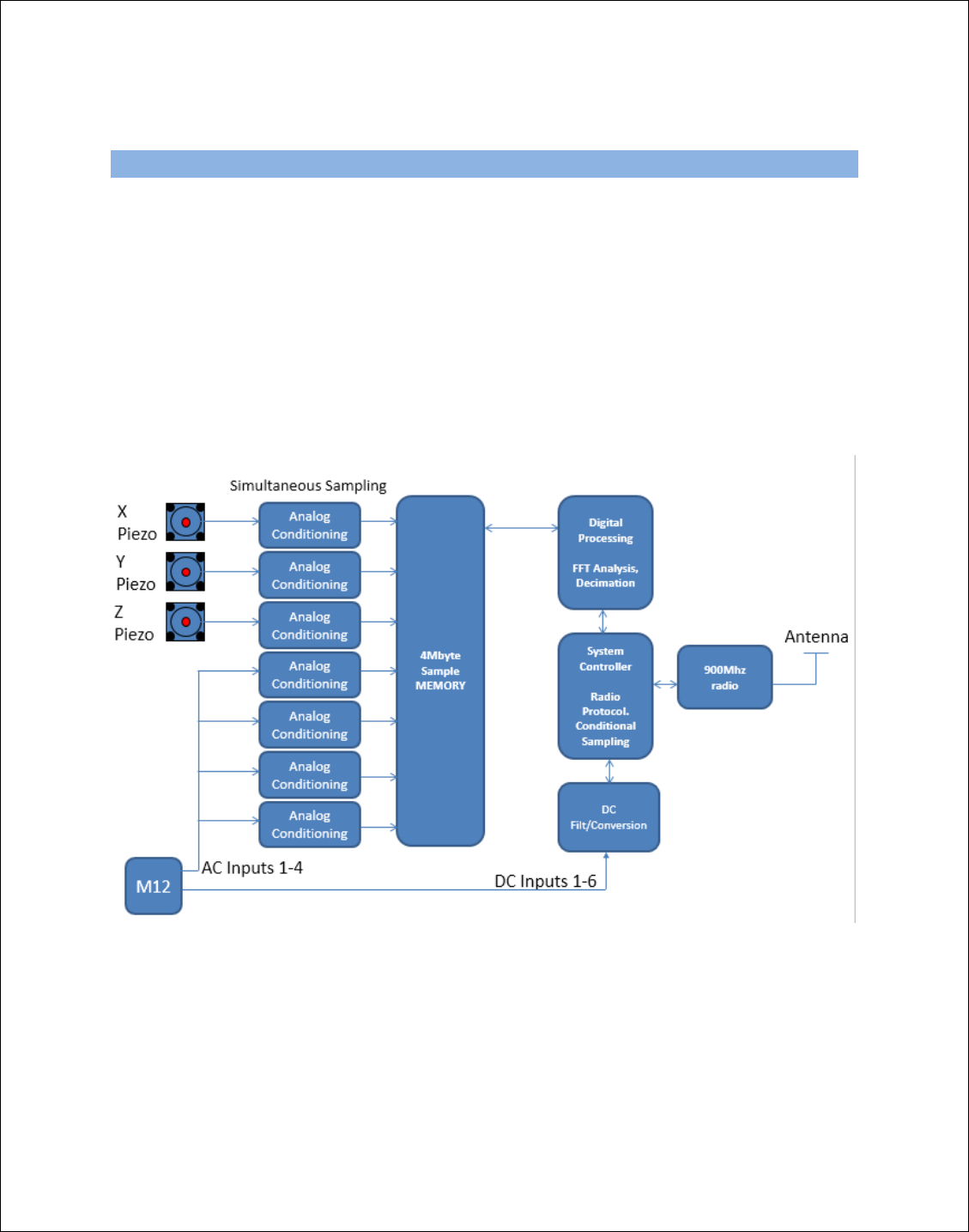
3. Overview
An overview of the STORMX unit is shown in the figure below. AC signals
come from internal Piezo sensors or from the external expansion port (M12
connector). The input signals pass through a conditioning block, then to an
A/D converter, and then are placed into system memory. The Digital
Processing block collects sampled data and provides additional functions
such as decimation and frequency analysis. The system controller
communicates over the radio interface to send and receive commands and
data. External DC inputs are received through the external M12 port and are
filtered and sampled and sent over the radio interface on command.
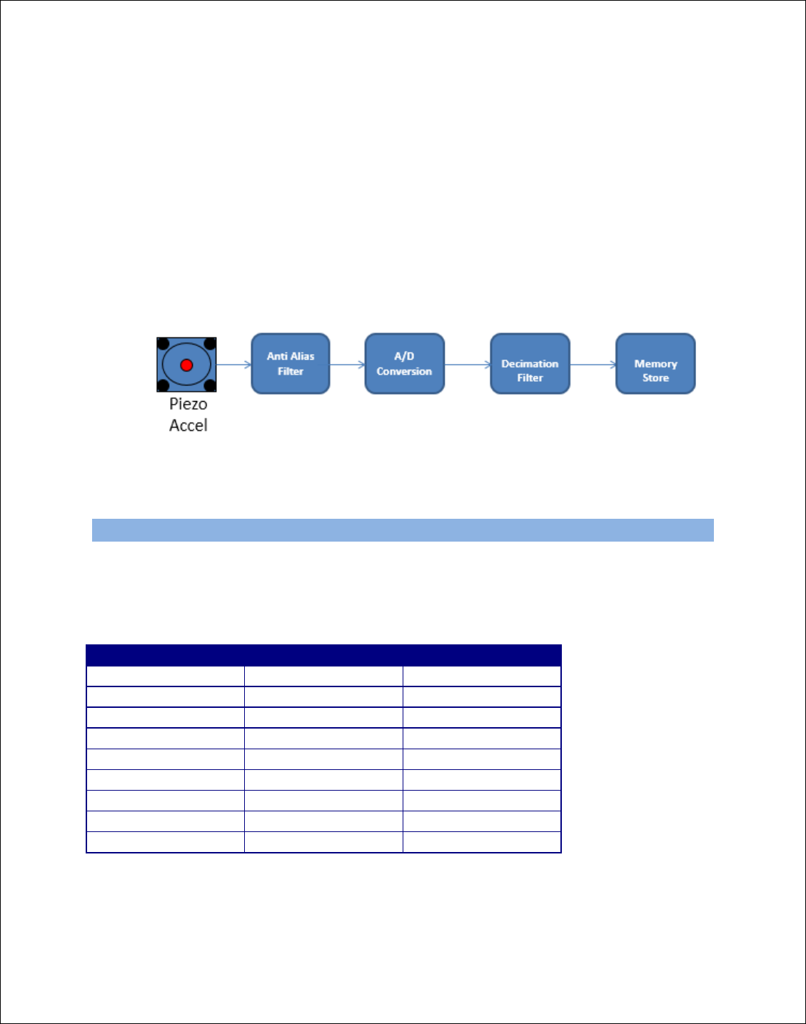
Analog Conditioning
The analog conditioning block is shown in the figure below. This
circuit is duplicated once per analog input. AC signals come from an
internal accelerometer or external M12 connector and then pass
through filtering before being converted by a high precision A/D
converter. The digital samples are filtered and decimated before being
stored to memory.
4. Internal Accelerometer Specifications
The internal accelerometers can be factory configured to support +-22g, +-45g,
+-95g, +-190g, +-450g
The following specifications are for the standard +-22g model
Parameter
Value
Comments
Freq response
2 to 6,000Hz
Range
+-22g
Factory Setting
Broadband noise
110uV
2hz-6,000Hz
Spectral noise
120 ug/root Hz
@10Hz
Spectral noise
40 ug/root Hz
@100Hz
Spectral noise
20 ug/root Hz
@1000Hz
Operating Temp
-40 to +125C
Sensing element
Piezo-Ceramic
Shear mode
Power
<22uA

5. External AC Signal Input Specifications
The external AC signals have input requirements as shown below. Uptime
solutions provides a conversion module that allows external ICP accelerometers
to be conditioned and connected to the M12 port.
Parameter
Value
Comments
Sample rate
64 to 20,000Hz
Software
Configuration
Low pass filter
25 to 8,000Hz
Automatic
High pass filter
0.2 Hz
Factory Setting
DC bias voltage
20V/4ma
Factory Setting
Resolution
16 bits at the
highest sample
rate
Higher resolutions
can be achieved
at lower sample
rates
Input impedance
>100K ohms
Signal Input
Voltage
0 to 2.5V
AC Signal voltage
+-1.20V with DC
offset required of
1.25V

6. External DC Input Specifications
Uptime solutions provides a conversion module that allows external DC sensors
to be conditioned and connected to the M12 port.
7. External Power Supply Specification
The external power supply has signals requirements as shown below. Uptime
solutions provides an IP67 power supply that meets this requirement. Multiple
nodes can be powered by a single power supply.
Parameter
Value
Comments
Input Voltage
4.3V
+-1%
Input Current
200ma
maximum

8. 900MHz Radio Specification
The 900MHz radio module has the following specifications.
Parameter
Value
Units
Operating
Frequency
902.2 to 927.8
MHz
Number of
Channels
32
Channels
Channel Spacing
750
kHz
Hop Sequence
6
Factory Setting
Data Rate
115
kbps
FCC/CA Approvals
FCC ID: 2ADT3-BA1000
This device complies with part 15 of the FCC Rules. Operation is subject to the following
two conditions: (1) This device may not cause harmful interference, and (2) this device
must accept any interference received, including interference that may cause undesired
operation.
Changes or modifications not expressly approved by the party responsible for
compliance could void the user's authority to operate the equipment.
NOTE: This equipment has been tested and found to comply with the limits for a Class B
digital device, pursuant to part 15 of the FCC Rules. These limits are designed to provide
reasonable protection against harmful interference in a residential installation. This
equipment generates, uses and can radiate radio frequency energy and, if not installed
and used in accordance with the instructions, may cause harmful interference to radio
communications. However, there is no guarantee that interference will not occur in a
particular installation. If this equipment does cause harmful interference to radio or
television reception, which can be determined by turning the equipment off and on, the
user is encouraged to try to correct the interference by one or more of the following
measures:
—Reorient or relocate the receiving antenna.

—Increase the separation between the equipment and receiver.
—Connect the equipment into an outlet on a circuit different from that to which the
receiver is connected.
—Consult the dealer or an experienced radio/TV technician for help.
In order to maintain compliance with FCC regulations, shielded cables must be used with this
equipment. Operation with non-approved equipment or unshielded cables is likely to result in
interference to radio and TV reception. The user is cautioned that changes and modifications
made to the equipment without the approval of manufacturer could void the user's authority
to operate this equipment.
Mobile Device RF Exposure Statement:
RF Exposure Statement: This device is only authorized for use in a mobile application. At
least 20 cm of separation distance between the StormX Model 1000 device and the user's
body must be maintained at all times.
The antenna used for this transceiver must not be co-located or operating in
conjunction with any other antenna or transmitter
Canada CA Suplement
"Son fonctionnement est soumis aux deux conditions suivantes: (1) cet appareil ne peut
pas provoquer d'interférences, et (2) cet appareil doit accepter toute interférence, y
compris celles susceptibles de provoquer le fonctionnement du dispositif."

9. Battery Considerations
All features of the StormX unit can be enabled whether on battery power or DC
power. Some advanced operational modes are not recommended when on
battery power. The unit is capable of sampling long time domain waveforms, and
can sample continuously. In battery operation, this will deplete the battery
quickly.
The batteries employed are high temperature Lithium-thionyl-chloride batteries
rated at an operational temperature of 125C and a peak current of 750ma and
continuous current of 375ma with U.L. Component Recognition, MH 12193.
The battery pack supports 7 Amp hours of power, allowing the unit to run
continuously with radio for 50-70 hours. Power down modes allow the system to
run for multiple years depending on software configuration. The unit delivers a
battery status to the SW to indicate remaining power, and Uptime Solutions
provides a power estimation chart (TBD) to select appropriate settings.
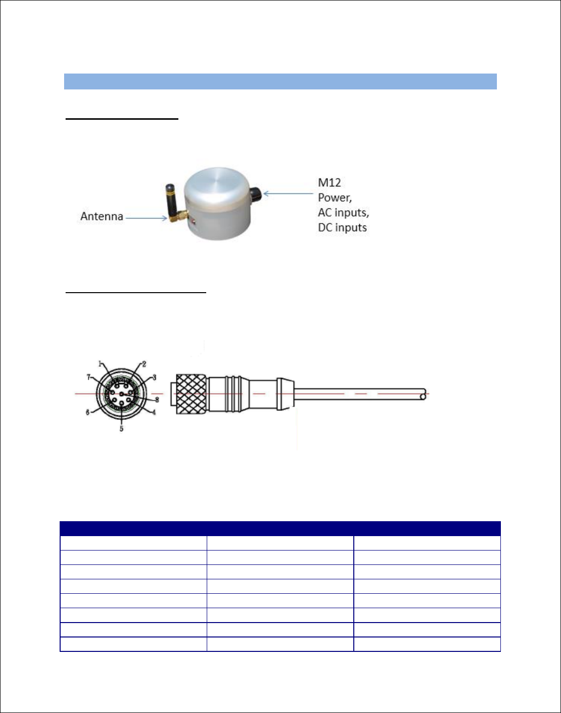
10. Connectors
Connector Location
The STORMX has connectors for 8 signals (M12) and antenna (RPSMA).
STORMX M12 Connector
The STORMX process connector provides a seamless connection from
STORMX to external power, AC sensors, or DC sensors. The pinout of the
connector is shown below.
A standard M12 cable (provided by Uptime Solutions) connects the STORMX
unit directly to the external process unit. Each signal in the connector has a
unique wire color. The following table shows the pin number, wire color, and
signal meaning on the connectors.
Pin Number
Wire Color
Signal Description
1
Black
+4.3V DC, 200ma
2
Brown
External AC channel1
3
Red
Ground
4
Orange
External AC channel2
5
Yellow
Reserved, tie to 4.3VDC
6
Green
External AC channel3
7
Blue
DC Mux
8
White
External AC channel4

11. Safety Precautions
This unit operates from batteries or an external DC feed. Extreme care must be
taken to insure this DC feed signal is not crossed with higher voltages (from the
mains), and that water or other contaminants at the power supply junction do not
allow the mains voltage to feed across to the DC line.
A Class 2 isolated power supply is required at minimum, and it should be
protected from water ingress.
A GFI circuit is required for the power supply mains feed.
Class 2 Compliance
Class 2 compliance requires a maximum power output availability of less than
100 watts for the component. The NEC is the source of the Class 2 Supply
definition. Due to its power, current and voltage limitations, a class 2 circuit
considers safety from a fire initiation standpoint and provides acceptable
protection against electric shock. Only the load side of a power supply with a
nameplate rating of less than 100VA can meet the class 2 circuit requirements.
Class 2 requires dry indoor use and is only for non hazardous location areas.
Battery Pack
All lithium thionyl chloride batteries should be disposed of by a certified
hazardous waste disposal facility. Contact Uptime Solutions for disposal
information or return batteries for proper disposal.