Urban Canyon Flight UC10X skyBeacon UAT Transponder User Manual UC10x Installation Manual
Urban Canyon Flight Inc skyBeacon UAT Transponder UC10x Installation Manual
UserManual.wiki
>
Urban Canyon Flight
>
UC10X User Manual
User Manual
Navigation menu
Upload a User Manual
Namespaces
Wiki Guide
HTML
PDF
Info
Views
User Manual
Discussion / Help
Navigation

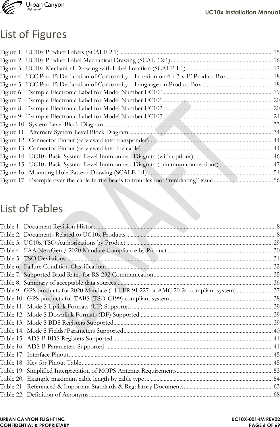

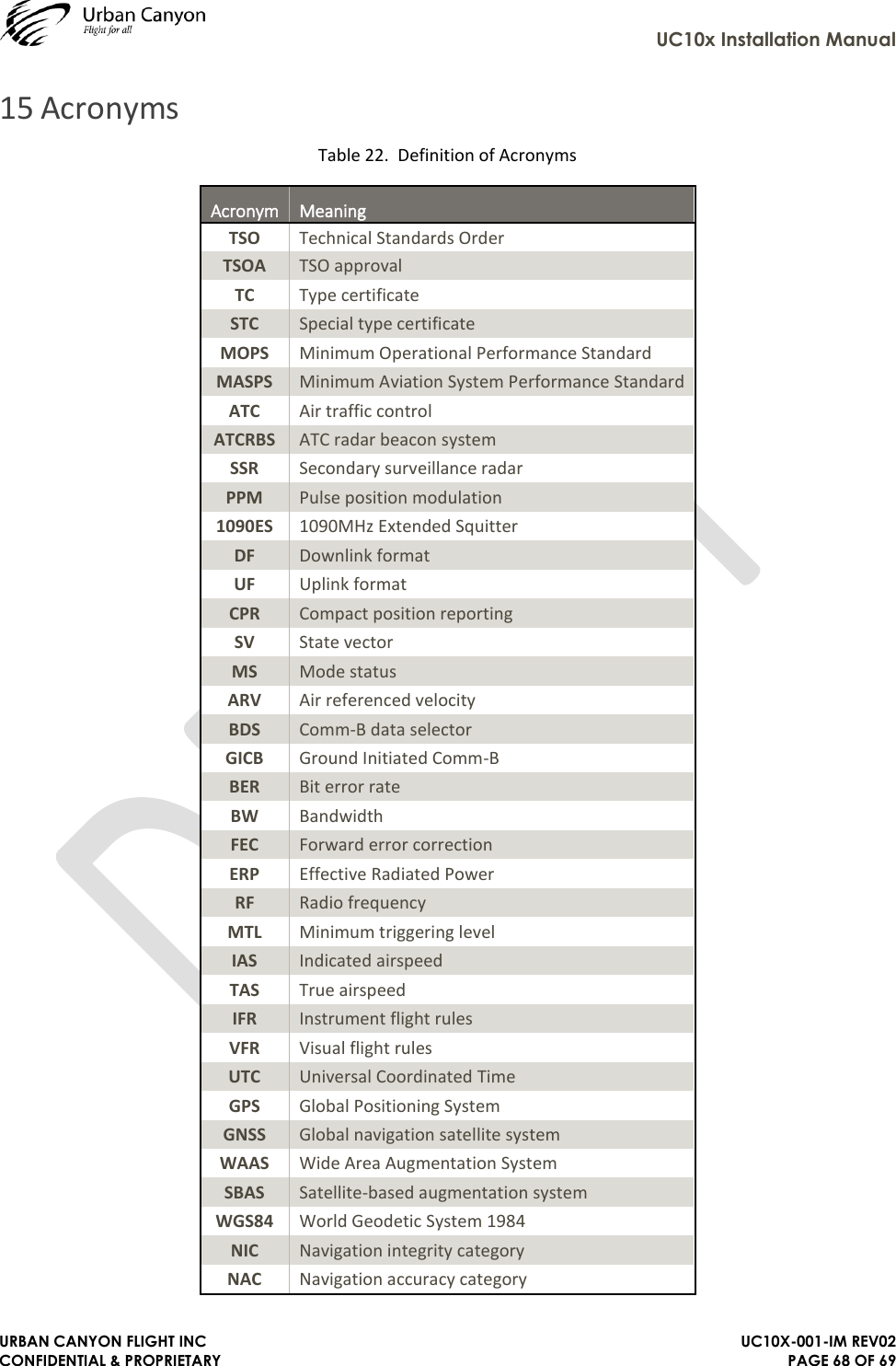
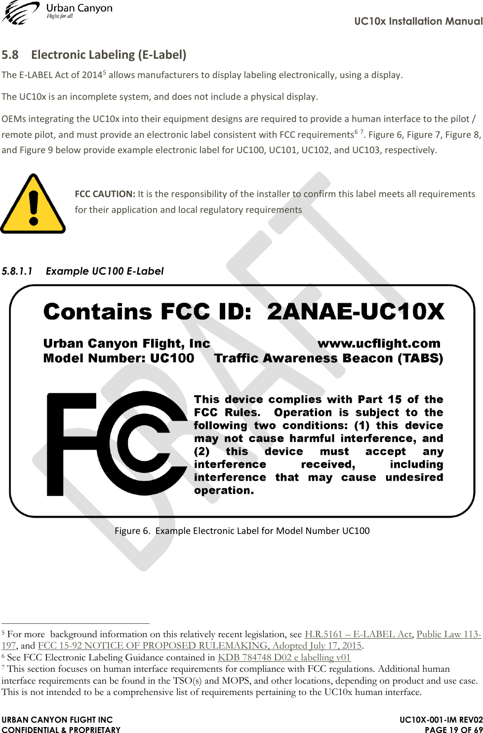
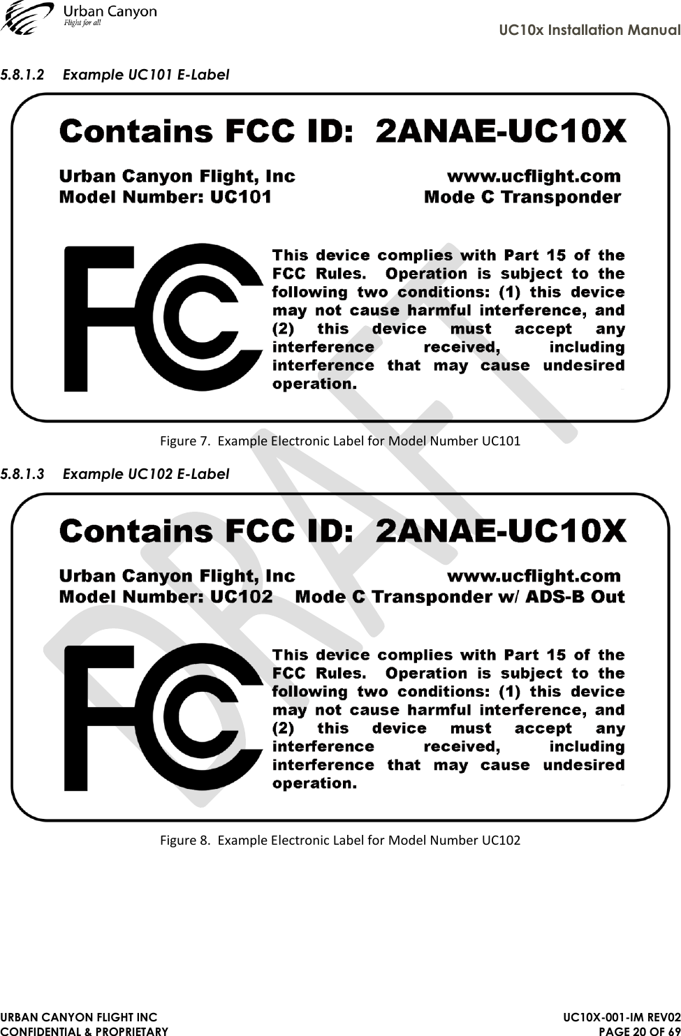
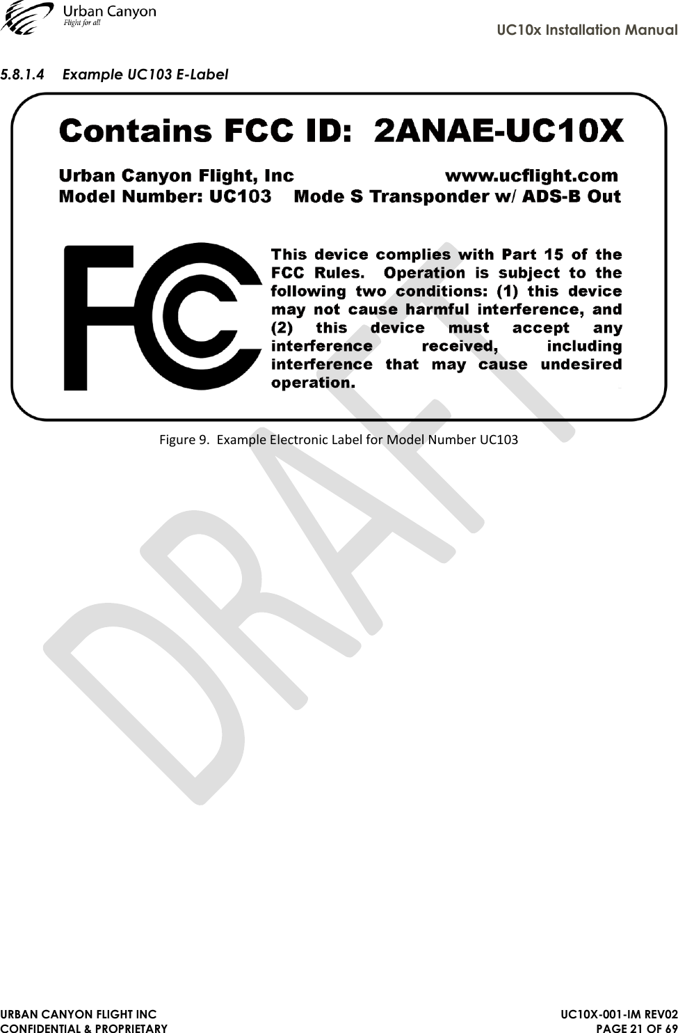
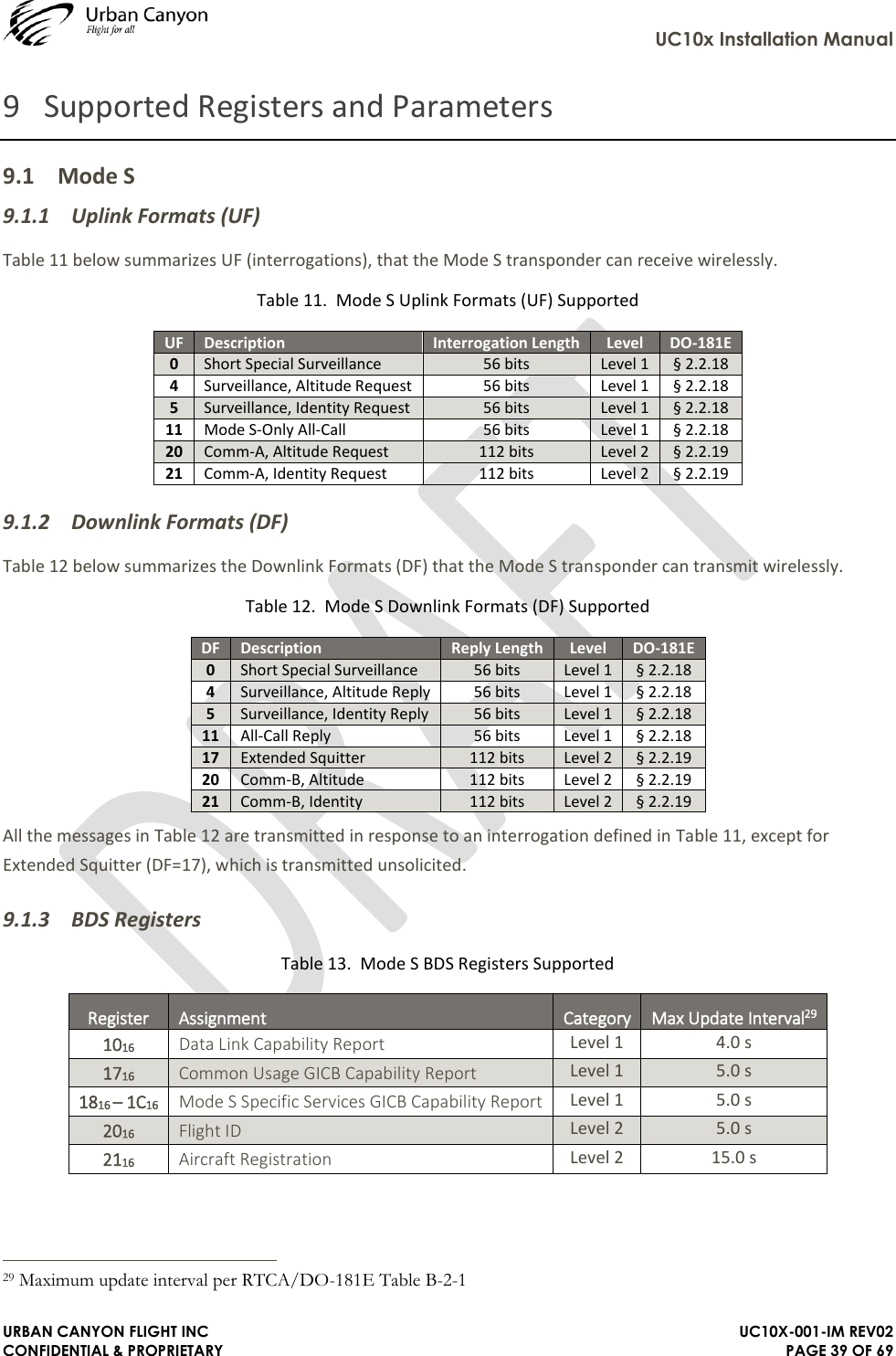
![UC10x Installation Manual URBAN CANYON FLIGHT INC UC10X-001-IM REV02 CONFIDENTIAL & PROPRIETARY PAGE 13 OF 69 5 FCC Certification and Compliance This section provides warning statements/disclaimers required by the FCC. Additionally, this section provides operating requirements and labeling requirements that comply with FCC requirements. Compliance with this section does not guarantee authorization of use. Requirements of other regulatory bodies (such as FAA and ICAO), discussed in part elsewhere in this document, will be required depending on the specific use case. Understanding the regulations are the sole responsibility of the end user. Changes or modifications not expressly approved by the manufacturer could void the user’s authority to operate the equipment. 5.1 FCC ID The UC10x family FCC ID is 2ANAE-UC10X 5.2 FCC Radiation Exposure Statements This equipment complies with FCC radiation exposure limits set for an uncontrolled environment. This equipment should be installed and operated with a minimum distance of 40 cm maintained between the radiator and any persons when the transponder is powered on and the radio in an active mode. The antenna(s) used for this transmitter must not be co-located (within 40 cm) or operating in conjunction with any other antenna or transmitter. 5.3 FCC Interference Statements This equipment has been tested and found to comply with the limits for a Class B digital device, pursuant to Part 15 of the FCC Rules. These limits are designed to provide reasonable protection against harmful interference in a residential installation. This equipment generates uses and can radiate radio frequency energy and, if not installed and used in accordance with the instructions, may cause harmful interference to radio communications. However, there is no guarantee that interference will not occur in a particular installation. If this equipment does cause harmful interference to radio or television reception, which can be determined by turning the equipment off and on, the user is encouraged to try to correct the interference by one of the following measures: • Reorient or relocate the receiving antenna. • Increase the separation between the equipment and receiver. • Connect the equipment into an outlet on a circuit different from that to which the receiver is connected. • Consult the dealer or an experienced radio/TV technician for help. This device complies with Part 15 of the FCC Rules [and with Industry Canada (IC) license-exempt RSS standard(s)]. Operation is subject to the following two conditions: (1) This device may not cause harmful interference, and (2) this device must accept any interference received, including interference that may cause undesired operation. FCC CAUTION: Any changes or modifications not expressly approved by the party responsible for compliance could void the user's authority to operate this equipment.](https://usermanual.wiki/Urban-Canyon-Flight/UC10X/User-Guide-3580719-Page-13.png)

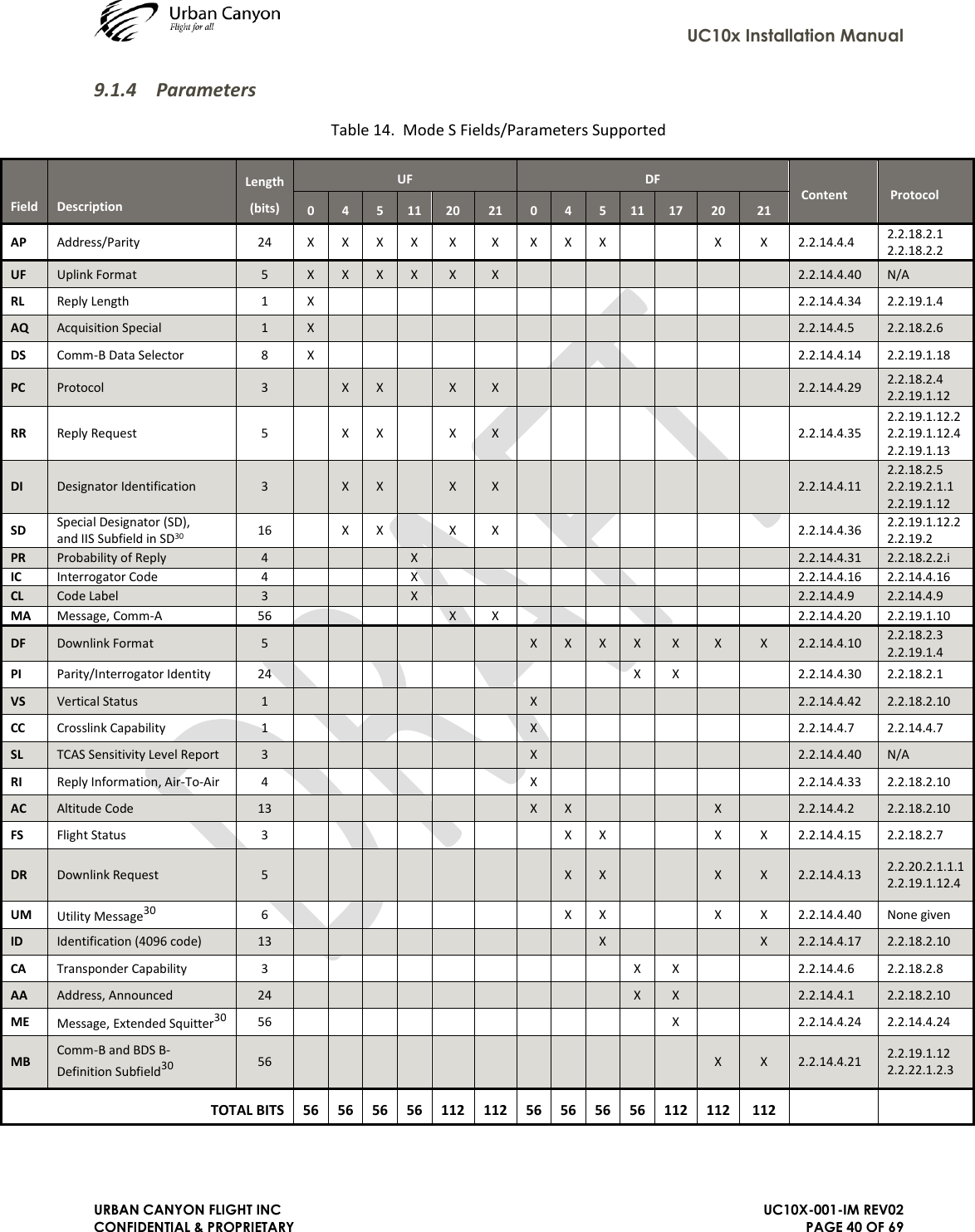

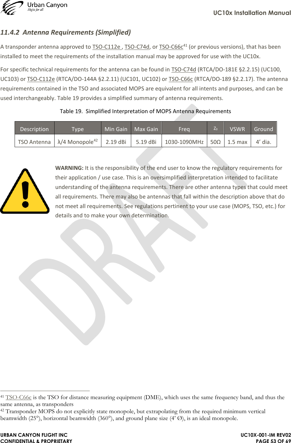
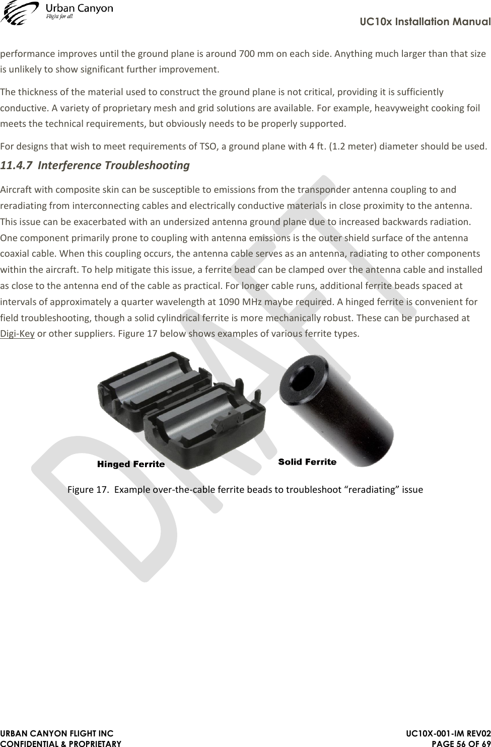
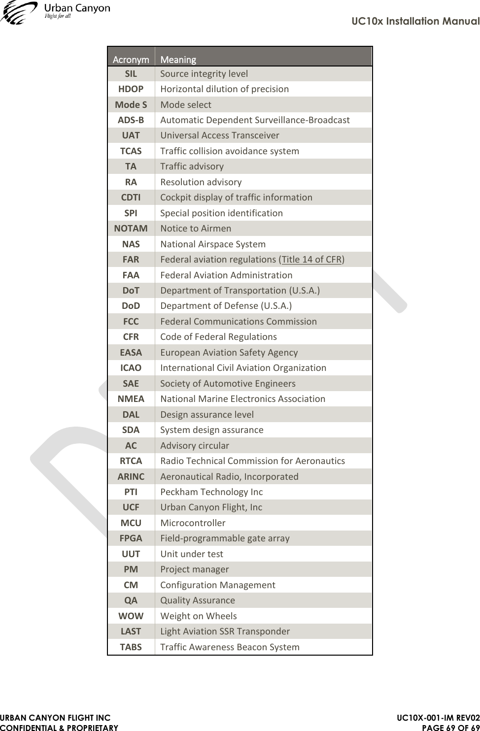
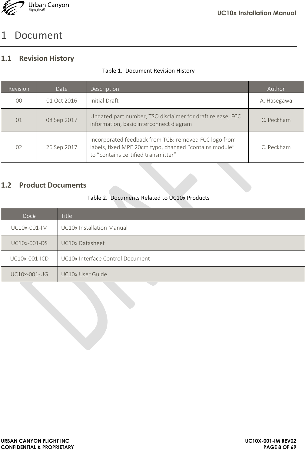
![UC10x Installation Manual URBAN CANYON FLIGHT INC UC10X-001-IM REV02 CONFIDENTIAL & PROPRIETARY PAGE 54 OF 69 11.4.3 Antenna Cable Design / Selection UC10x system does not include an antenna. The UC10x family is designed to meet high power (unrestricted altitude) requirements with an allowance of 0 dB min (UC10x directly connected to antenna) to 1.5 dB maximum insertion loss in the connectors and cables used to connect it to the antenna. Excessive loss will degrade both transmitter output power and receiver sensitivity. An acceptable cable: ➢ Has power rating of 3W average at 1GHz minimum (10+ W preferred) ➢ Has voltage rating of 300 VRMS minimum (1,000+ VRMS preferred) ➢ Has less than 1.5 dB loss for the required cable run length (1 dB preferred) ➢ Has a characteristic impedance (Z0) of 50 Ω ± 5 Ω ➢ Has double-braided screens consisting of a combination foil and braid screen ➢ For installations that require frequent disassembly/reassembly, select connectors rated for number of mating cycles ➢ Uses an SMA male on one end (for the UC10x), and mates with the antenna on the other (depends on antenna selected) Once the cable run length is known, a cable type with low enough loss per meter that meets the above requirements can be chosen. Longer runs require lower loss (usually physically thicker) cable. Consider moving the transponder closer to the antenna to minimize the losses in the antenna cable – subject to the limits identified above, the transponder can be at any distance from the control head without affecting performance in any way. Table 20 below is a guide to the maximum usable lengths for various common cable types. This table uses typical cable loss data to calculate maximum cable length assuming 1.5dB cable loss. Actual cable loss will vary between manufacturer and may change after use (e.g. due to repeated cable bending) and should always be verified through measurement by the end user / installer. Table 20. Example maximum cable length by cable type Type Jacket Dia. Insertion Loss (dB/ft) Max Cable Length (ft) Insertion Loss (dB/m) Max Cable Length (m) RG58-TPX 0.190" [4.83mm] 0.58 2.6 1.90 0.8 RG178B/U 0.072" [1.83mm] 0.44 3.4 1.46 1.0 PE-047SR 0.047" [1.19mm] 0.40 3.8 1.31 1.1 RG316/U 0.098" [2.49mm] 0.38 3.9 1.25 1.2 RG316-DS 0.114" [2.90mm] 0.26 5.7 0.86 1.8 RG58C/U 0.195" [4.95mm] 0.20 7.5 0.66 2.3 RG58-P 0.159" [4.04mm] 0.17 8.7 0.57 2.6 RG8X 0.242" [6.15mm] 0.14 11.1 0.44 3.4 RG141A/U 0.190" [4.83mm] 0.13 11.5 0.43 3.5 RG213/U 0.405" [10.29mm] 0.08 18.8 0.26 5.7 RG218/U 0.870" [22.1mm] 0.04 39.5 0.12 12.0](https://usermanual.wiki/Urban-Canyon-Flight/UC10X/User-Guide-3580719-Page-54.png)