Urologix CW5000A RFID Card Transmitter User Manual 532897
Urologix Inc. RFID Card Transmitter 532897
UserManual.wiki
>
Urologix
>
CW5000A User Manual
Manual
Navigation menu
Upload a User Manual
Namespaces
Wiki Guide
HTML
PDF
Info
Views
User Manual
Discussion / Help
Navigation
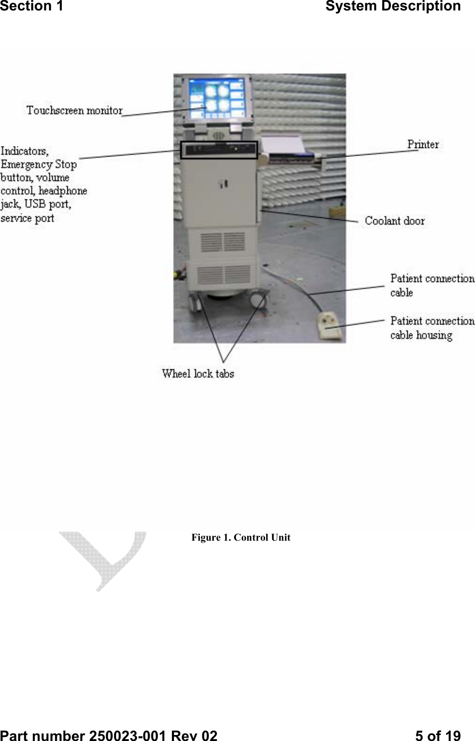
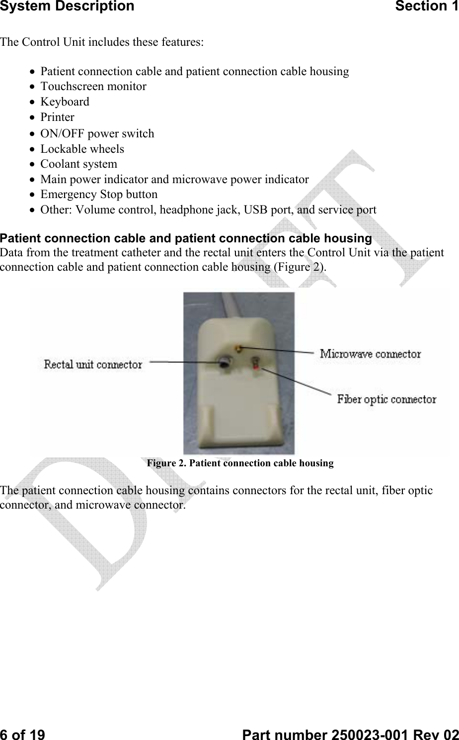
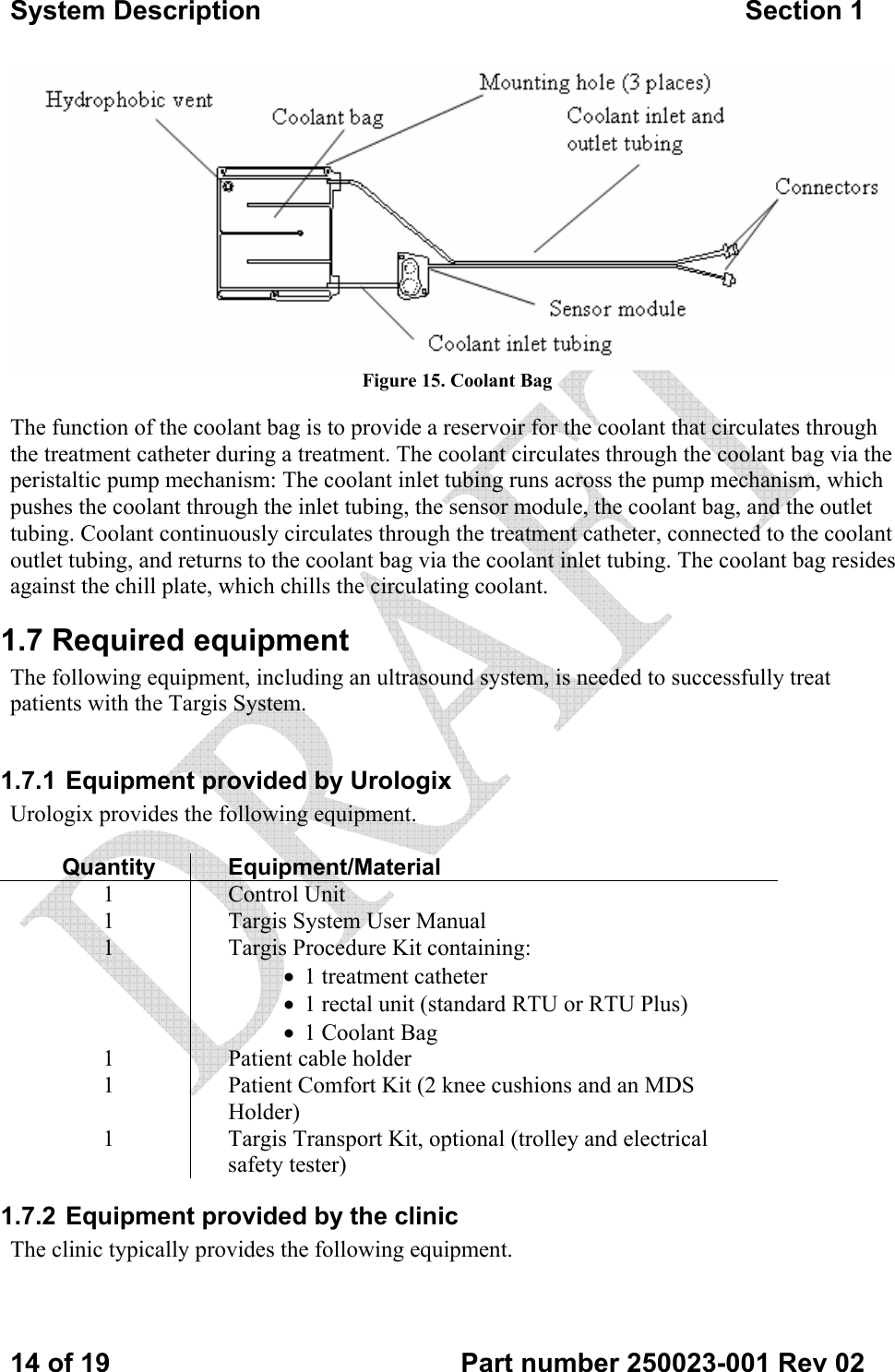
![System Description Section 1 16 of 19 Part number 250023-001 Rev 02 The equipment must be connected to a fully tested, hospital-grade power outlet with adequate grounding. Power requirements Control Unit, Model 5000E (Europe): 220/240 V [+/- 10%] (8 A) Single phase 50 or 60 Hz Control Unit, Model 5000A (US): 110/120 V [+/- 10%] (15 A) Single phase 50 or 60 Hz Control Unit, Model 5000J (Japan): 100 V [+/- 10%] (15 A) Single phase 50 or 60 Hz If required, an equal potential ground cable should be connected to the Control Unit (Figure 16) and the appropriate ground. Figure 16. Control Unit rear cover](https://usermanual.wiki/Urologix/CW5000A/User-Guide-532897-Page-16.png)