Utica Boilers Je Operation And Installation Manual
2015-05-18
: Utica-Boilers Utica-Boilers-Je-Operation-And-Installation-Manual-719528 utica-boilers-je-operation-and-installation-manual-719528 utica-boilers pdf
Open the PDF directly: View PDF ![]() .
.
Page Count: 16
INSTALLATION AND OPERATING
INSTRUCTIONS
CSD-1 COMMERCIAL BOILER CONTROLS
P/N 240010413, Rev. A [12/2013]
SUPPLEMENTAL
Your commercial boiler is furnished with combustion side
water or steam controls to meet our interpretation of the
American Society of Mechanical Engineers (ASME) Safety
Code for Controls and Safety Devices for Automatically
Fired Boilers, No. CSD-1.
Installation shall conform to the requirements of the
authority having jurisdiction, or, in the absence of such
requirements, to the National Fuel Gas Code, ANSI-Z223.1/
NFPA-54 (latest revision). Where required by the authority
having jurisdiction, the installation shall conform to the
American Society of Mechanical Engineers (ASME) Safety
Code for Controls and Safety Devices for Automatically Fire
Boilers, No. CSD-1.
CSD-1 controls and this installation may be subject to
approval by local inspectors. Additional parts or equipment
may be required. Consult local authorities having
jurisdiction before the installation of the boiler.
CSD-1 controls furnished with commercial boilers are
applicable to boilers with inputs above 400,000 Btu/hr.
(Models 500-1500)
Additional parts required by CSD-1 standards may be
necessary to make this boiler compliant. This supplemental
instruction manual should be used in conjunction with the
Installation, Operation and Maintenance manual for your
specic boiler.
CSD-1 Component Installation
Based on parts listed in Installation, Operation and
Maintenance manual for your particular boiler, the following
changes should be made:
Complete Boiler Material List - See Table #1: CSD-1
Complete Boiler Material List.
Combustion Side Control :
• Models 300 and 400, no changes are required to
existing gas trains.
• Models 500 through 1500 requirements include:
A. Intermittent pilot control module is required to
have maximum 15 second pilot ame establishing
period and ability to perform safety shutdown and
lockout in event of loss of ame signal at pilot.
B. The intermittent pilot module and manual reset
switch are used to replace the existing pilot
module.
C. Also, an independent pilot gas line which includes
manual shutoff valve, pressure regulator and
safety shutoff valve, two leak test valves on
main gas valve, and manual shutoff valve located
downstream of the main gas valve are added. See
See Table #2: CSD-1 Component Carton Material List
for component carton material list which replaces the
corresponding list in the installation manuals.
• See Table #3: CSD-1 Electronic Ignition Base Material
List.
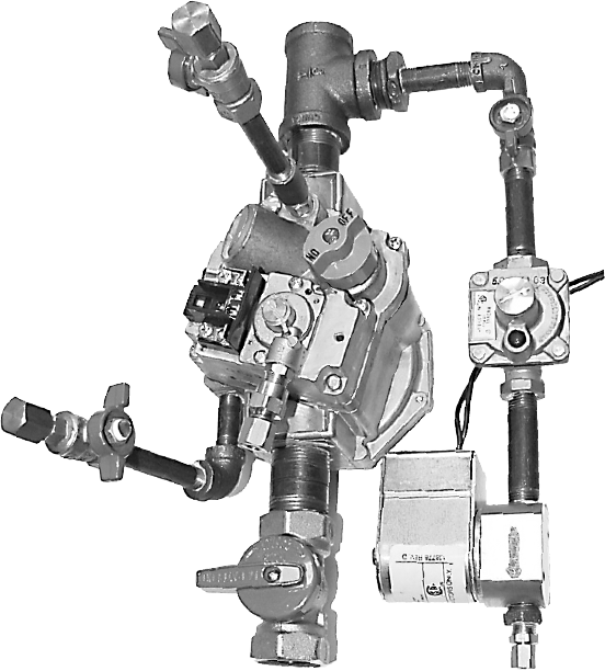
• Installed locations of additional components see Figures
1a and 1b.
For CSD-1 combustion side control, light off sequence is as
follows:
1.
Turn on power. Set thermostat to call for heat.
2.
Ignition starts to spark and lights pilot ame.
3.
Ignition continues sparking about 12 seconds after pilot
lights.
4.
Main burners ignite.
NOTICE
A longer pilot ame recognition time is a design
feature of this module and is correct.
Gas Pressure Requirements
• Maximum allowable inlet gas pressure (natural gas
only) to controls in CSD-1 gas train is 14” w.c. (½
psig).
• Verify inlet gas pressure is at least 5” w.c. but no
greater than 14” w.c.
• If gas pressure entering the building is greater than 14”
w.c., installing contractor must provide overpressure
protection on downstream piping to prevent buildup of
downstream pressures in excess of 14” w.c. in event
the fuel system pressure regulator fails.
• Alternatively, gas pressure entering the building may
be reduced with additional gas pressure regulator
outdoors. If inlet gas pressure to this additional
regulator is less than 14” w.c., then overpressure
protection may not be required.
• Consult local authority(s) having jurisdiction before
installing gas supply piping to the boiler.
CSD-1 COMMERCIAL BOILER CONTROLS
WARNING
Fire, explosion, asphyxiation and electrical shock
hazard. Improper installation could result in death
or serious injury. Read this manual and understand
all requirements before beginning installation.
!
2
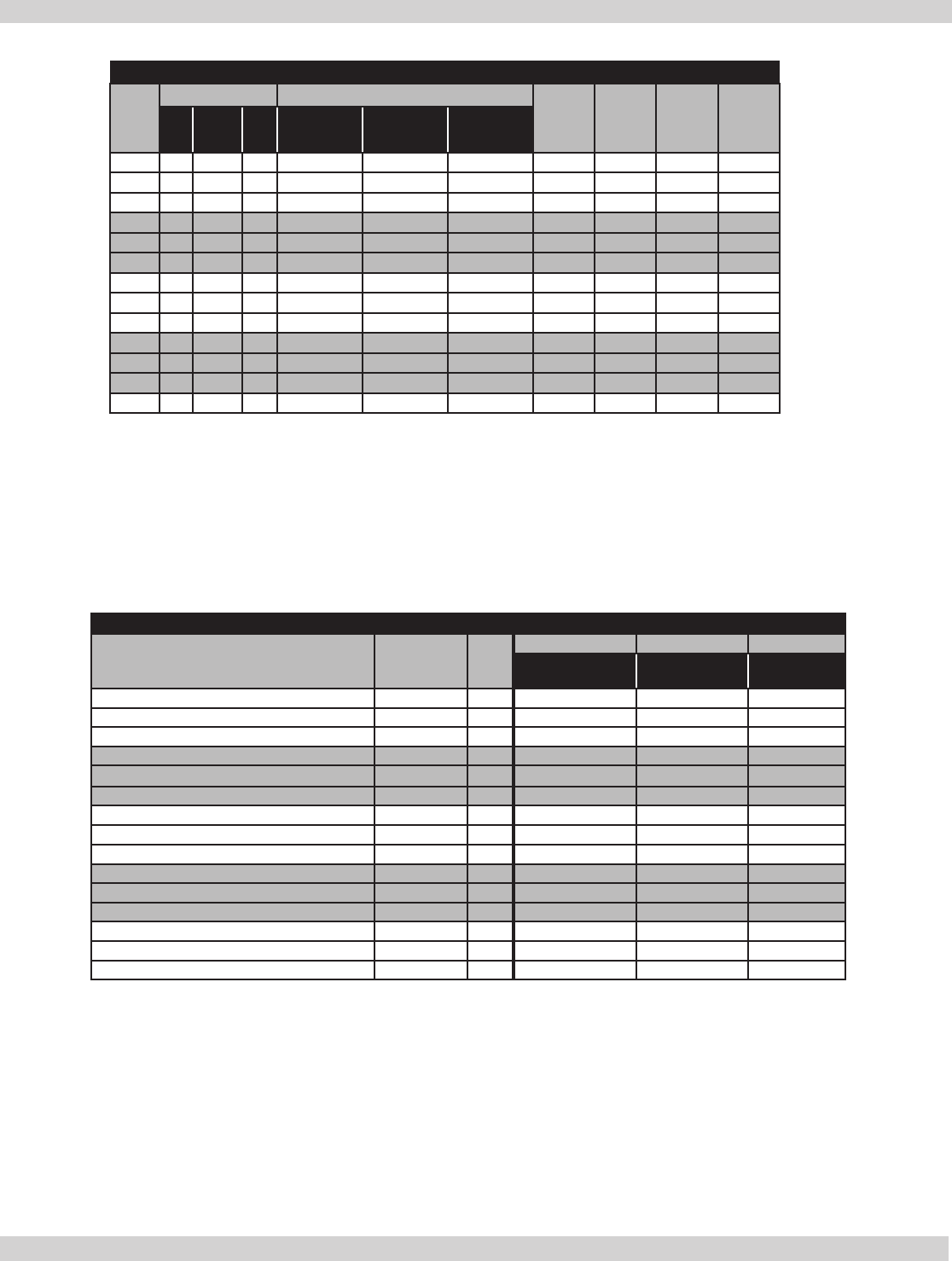
Table #1: CSD-1 Complete Boiler Material List
Model
Sections CSD-1 Component Carton a & b Steam
Trim
Cartond
CSD-1
AC
Carton
Jacket
End
Panel
Carton
Base
End
Panel
Carton
L Inner R 300 CSD-1 400 CSD-1 500 CSD-1
300 1 2 1 SA-1 300 1 1
400 1 3 1 SA-1 400 1 1
500 1 4 1 1 SA-1 500 1 1
600 1 5 1 2 SA-2 600 1 1
700 1 6 1 1 1 SA-2 700 1 1
800 1 7 1 2 SA-3 800 1 1
900 1 8 1 1 1 SA-3 900 1 1
1000 1 9 1 2 SA-3 1000 1 1
1100 1 10 1 1 2 SA-3 1100 1 1
1200 1 11 1 3 SA-3 1200 1 1
1300 1 12 1 1 2 SA-3 1300 1 1
1400 1 13 1 1 2 SA-3 1400 1 1
1500 1 14 1 3 3 SA-4 1500 1 1
a. Boilers having total inputs of 400 MBH or less as complying with ANSI Z21.13 (Models 300 and 400), the standard combustion
side controls meet CSD-1 and no changes to the standard component carton are required.
b. There are additional parts on base assemblies for boilers having total inputs from 500 to 1,500 MBH (Models 500 to 1500)
to meet CSD-1. See “Table 2: CSD-1 Component Carton Material List” for details.
c. For steam boilers, there is an additional CSD-1 steam trim carton for gravity or condensate pump return (Part# 41257103)
or an additional CSD-1 steam trim carton for boiler feed pump return (Part# 41257104). See appropriate CSD-1 Steam
Trim Carton Material List (Tables 5a and 5b) for details.
Table #2: CSD-1 Component Carton Material List
Description Stock No. Unit
550001664 550001665 550001666
300 CSD-1 400 CSD-1 500 CSD-1
300 Base Assembly CSD-1 550001670 Ea. 1
400 Base Assembly CSD-1 550001671 Ea. 1
500 Base Assembly CSD-1 550001672 Ea. 1
300 Intermediate Jacket Carton 550001673 Ea. 1
400 Intermediate Jacket Carton 550001674 Ea. 1
500 Intermediate Jacket Carton 550001675 Ea. 1
300 Draft Hood 42557113 Ea. 1
400 Draft Hood 42557114 Ea. 1
500 Draft Hood 42557115 Ea. 1
Control Panel Assembly 550001801 Ea.
Control Panel Assembly CSD-1 300/400 550001869 Ea. 1 1
Control Panel Assembly CSD-1 500 550001870 Ea. 1
Top Front Panel 300 109009216 Ea. 1
Top Front Panel 400 109009217 Ea. 1
Top Front Panel 500 109009210 Ea. 1
Boilers having total inputs of 400 MBH as complying with ANSI Z21.13 (Models 300 and 400), the standard combustion side controls
meet CSD-1 and no changes to the standard component carton are required.
MATERIAL LISTS
3
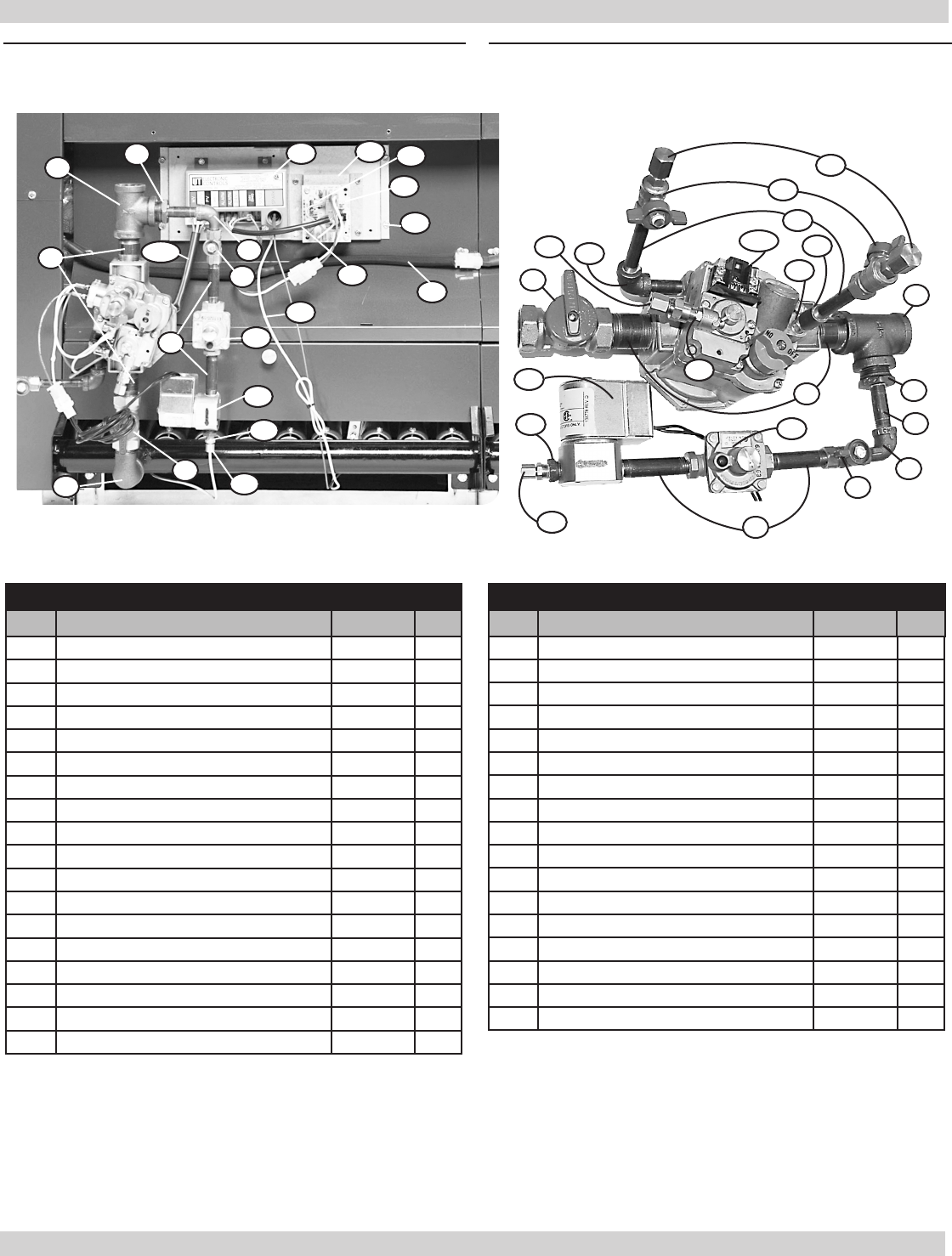
Table #3: CSD-1 Electronic Ignition Base Material List
Item Description Part No. Qty.
1 ¾” 90 Street Elbow Back 14693040 1
2 ¾” Manual Shutoff Valve 14657001 1
3 ¾” x 2” Nipple Black 14607201 2
4¾” Tee Black 14693076 1
5 ¾” x ¼” Bushing 1060002 1
6 ¼” x 2” Nipple Black 1310018 1
7 ¼” Street Elbow Black 14657007 1
8 ¼” Manual Shutoff Valve 14657002 1
9 ¼” x 2½” Nipple Black 14607000 2
10 ¼” Gas Pres. Regulator, 6” w.c. 14657004 1
11 ¼” Magnetic Valve w/Connector Assembly 43357103 1
12 ⅛” NPT x ⅛” Tube M. Connector 14657019 1
13 ¼” x ⅛” Bushing 14657008 1
14 Control STP W/Alarm 1140007 1
15 Control Mounting Panel, CSD-1 24 GA Galv 109006833 1
16 Control CSD Lockout Daughter Board 1140008 1
17 Control Mounting Panel 109006832 1
18* Screws, #8 x ⅜ Self Tap 201000001 8
19a* Harness CSD-1 Control (300, 400) 1263016 1
19b Harness CSD-1 Control (500) 1263019 1
20 Harness CSD-1 Control 240006623 1
21 Compression Fitting, ⅛”NPT x ¼” Tube 14657025 1
22 Brass Coupling, Male ⅛” x 5/16”-24 14657024 1
23 ⅛” x 2½”” Nipple Black 14607804 2
24 ⅛” 90 Elbow (500 Only) 14657010 1
25 ⅛” Manual Shutoff Valve 14657003 2
26 ⅛” Pipe Cap 14657012 2
27a* Gas Valve, Electronic Ignition, Nat. (300, 400) 14662315 1
27b Gas Valve, Electronic Ignition, Nat. (500) 14663001 1
28 ⅛” Coupling Steel 14657013 1
29 CSD-1 Pilot Outlet Adapter 43357104 1
30 Wire Harness, Base to Base 240006732 1
31* ⅛ x 1½, Nipple, Black (300, 400 Only) 14657009 1
32 Wire Jumper, CSD-1 Board (Orange) 1263017 1
33 Ground Wire, Spark (White) 371-1-21.01 1
*Not Shown
Table #3: Continued
Item Description Part No. Qty.
1
2
2
3
3
4
4
5
5
6
7
7
8
8
9
9
10
10
11
11
12
12
13 13
14 15
16
17
19b
20
21
22
23
24
26
27b 28
29
30
32
33
25
MATERIAL LISTS
Figure 1a - CSD-1 500 Gas Train Figure 1b - CSD-1 500 Gas Train
4
WATER LEVEL
29” TO FLOOR
Steam Side Control - Two low water cutoff devices and
two pressuretrols, one with auto reset and the second with
manual reset, are required. In order to make the two
low water cutoff devices work in the appropriate
sequence, manufacture recommends locating both
devices at same end of boiler.
There are three different control systems for three different
types of condensate returns.
Identify the three different types of condensate returns:
• Gravity return - condensate is returned by gravity.
• Condensate pump return - condensate is returned
by pump(s), controlled by the water level in the
condensate receiver tank.
• Boiler Feed Pump Return - condensate is returned by
pump(s), controlled by the water level in the boiler.
Normal
Water Line
STEAM SIDE CONTROLS
Figure 2 - Steam Boiler Feed Pump Return
Figure 3 - Steam Gravity and Condensate Pump Return
Gravity Return And Condensate Pump Return
With gravity and condensate pump return, additional
control components are the same. See Table #5a and
Figure #2 for tappings.
• Tappings B & B location shown in Figure #2.
Installation shown in Figure #3, Primary LWCO and
Pressuretrol with gauge glass set.
• Tappings D or F (Figure #2)- Manual reset pressuretrol
and ¼” 90° brass syphon.
• Tappings E & F - Secondary LWCO (w/manual reset).
Use in conjunction with primary LWCO equipped on
boiler.
When using two LWCOs, place manual reset lower than
automatic LWCO. Water must be visible in gauge glass
when manual reset trips.
• Figure 3 shows how to raise automatic (Series 67)
LWCO 1-inch.
• Remove 1” from long side of ¼” diameter 90° brass
siphon tube.
• Remove nipple in series 67 and replace with 1 ½” long
nipple and street elbow.
• Water level control device located on condensate
receiver tank and controls condensate return pump is
not supplied.
Table #5a: CSD-1 Steam Trim Carton Material List for Gravity Return
or Condensate Pump Return (Part No. 41257103)
Item Description Part No. Qty.
1 LWCO w/Manual Reset (secondary) 240007388 1
2 Bushing, Steel or Cast 1” x 1¼” 14657016 1
3 Pressure Switch Control, Manual Reset 14662311 1
4 90° Brass Syphon, ¼” 14643004 1
5 ELB,ST,1/2”,45 DEG.BRASS 240007541 1
6 NIPPLE 1/2” X 1/2”LG BRASS 240007542 1
5
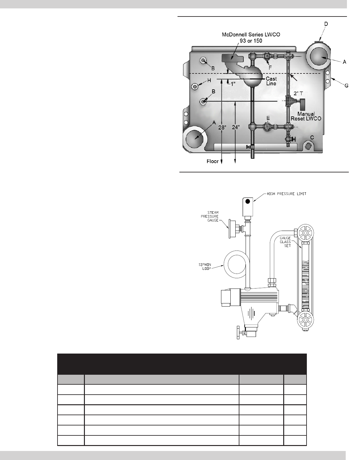
Boiler feed pump return additional parts See Table #5b.
See Figure #2 for installed locations of additional parts.
•Tappings B & B - Water gauge glass set and
pressuretrol (requires ttings 4-7 in Table #5b).
•Tapping D - Steam gauge and pressuretrol (requires
tting 8 in Table #5b).
•Tappings E & F - LWCO (auto and manual) and
pump control. Installer supply and size the steam
(top) and water (bottom) equalizing pipe lengths so
the horizontal cast line on the control body is 28”
above oor. Secondary control is 24” above the oor.
See Figure #2.
Table #5b: CSD-1 Steam Trim Carton Material List For
Boiler Feed Pump Return (Part No. 41257104)
Item Description Part No. Qty.
1 Pressure Switch Control, Manual Reset 14662311 1
2 LWCO and Pump Control (primary) 14626306 1
3 LWCO, MAN RESET, CSD-1 APRVD, SHT PROBE 240007388 1
4 90° Brass Syphon, ¼” 14643004 1
5 Brass Nipple, ½” x 3½” 14607024 2
6 Brass Tee, ½” x ½” x ¼” 14693051 2
7 Brass Coupling, ½” 14693052 2
8 Bushing, ½” x ¼” 1060001 1
BOILER FEED PUMP RETURN
6

Call For Heat
Control recognizes call for heat when power is applied
to 24V terminal on control module. Since control
receives signal from the thermostat, when call for heat is
terminated, heating cycle immediately terminates and all
control outputs will shut off.
Ignition Trial Period
Control energizes pilot gas valve and spark outputs for
ignition trial time of 12 seconds. If ame is sensed during
12 seconds of ignition trial, spark output is de-energized,
main gas valve is energized, and control enters steady heat
mode. If ame is not established within ignition trial period,
control de-energizes the spark and gas valve and operates
as described below in Ignition Failure/Re-try Sequence.
Ignition Failure/Re-Try Sequence
After an unsuccessful ignition trial, control checks to see
if maximum number of ignition trials (2 trials) has been
completed. If maximum number of ignition trials has been
completed, control will lockout. See Lockout (next page) for
details.
If maximum number of ignition trials has not been
completed, control delays for 5 minute inter-purge period.
After the inter-purge, control attempts another ignition
trial. Refer back to Ignition Trial Period for details.
Steady-State Heating
Control keeps pilot gas valve and main gas valve energized
while continuously monitoring call for heat and ame
status. Control will remain in this steady-state heating
mode until power is removed by (a) thermostat satised,
(b) pressure switch opening, or (c) ame being lost.
If call for heat is satised, power is removed from control,
de-energizing pilot gas valve and main gas valve.
If ame is lost, control will shut off main gas valve within
one second, leave pilot gas on, and immediately start
ignition trial. Control checks to see if maximum number
of ame losses (2 per call for heat) has been reached.
If maximum number of ame losses has been reached,
control locks out. See Lockout section for details.
PILOT
SEQUENCE OF OPERATION
7

Gas Valve Sensing
If either or both the pilot and main gas valves are sensed
to be on when commanded to be off, or if no voltage
appears at gas valve output which was commanded on,
control will shut off all outputs and enter either “soft” or
“hard” lockout state. Main valve is interlocked with the pilot
valve and voltage can only be detected on main valve when
pilot valve is energized. Control locks out the rst time
as “soft” lockout, then retries after 5 minutes and enters
“hard” lockout state. Lockout should be manually reset as
described in “Lockout.”
Flame Present With Gas Off
If ame is sensed for longer than 2 seconds during a period
when gas valve should be closed, control will enter lockout.
Power Interruptions
Power interruptions less than 0.15 seconds will not
cause control to interrupt heat sequence while power
interruptions over 0.25 seconds will cause the control
to reset lockout and ignition trial counters. Power
interruptions of any duration will not cause a lockout or any
other operation requiring manual intervention.
Lockout
Controller automatically resets from rst lockout in 5
minutes. If second lockout occurs before call for heat is
satised, it will require manually resetting by depressing
red button on CSD-1 daughter board. This can be reached
with a pencil through the vent holes. A red LED will also
indicate lockout and can be seen through the vent holes.
SEQUENCE OF OPERATION
8
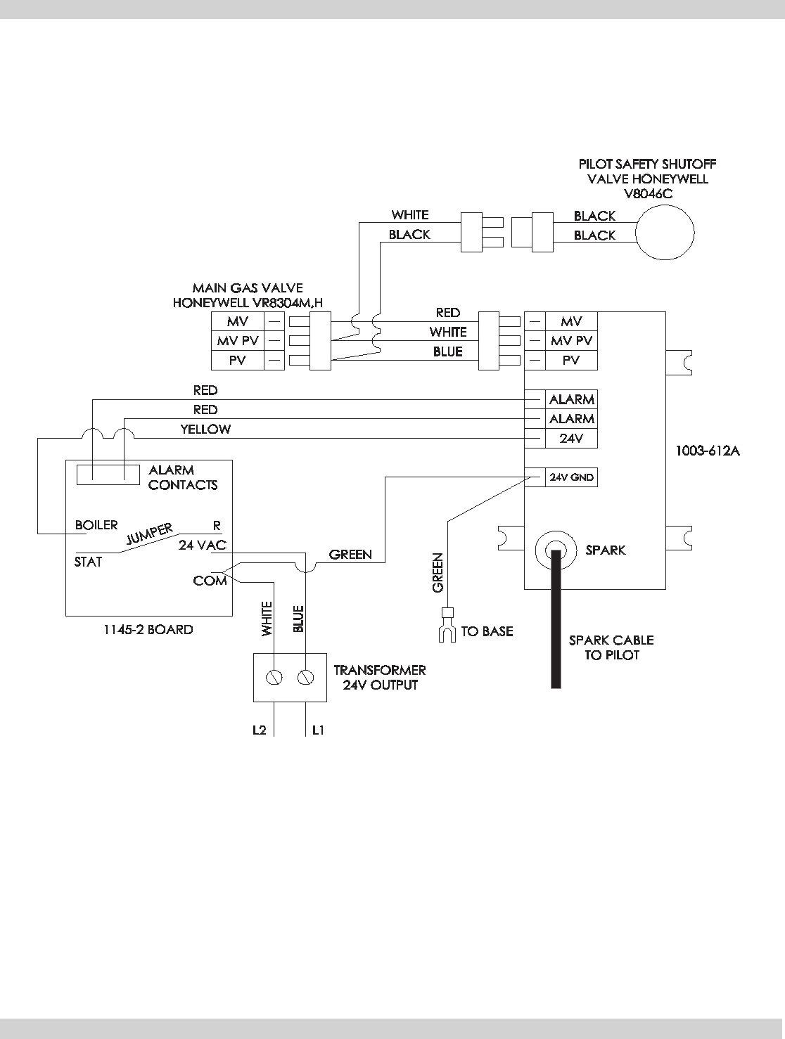
The suggested schematic wiring diagrams are included. Please use the appropriate one for the installation.
CSD-1 HONEYWELL VR8304M,H MAIN GAS VALVE CONTROL WIRING
ELECTRICAL WIRE DIAGRAMS - GAS VALVE CONTROL WIRING
9

ALARM
CONTACTS
JUMPER
UT 1145-2
BOILER
STAT
COM
24 VAC
R
PILOT SAFETY
SHUTOFF
VALVE
BLACK
BLACK
WHITE
BLUE
D D
MAIN GAS VALVE
ROBERT SHAW 7000 DE RHC
TR TH
SPARK
CABLE
TO PILOT
GREEN
SPARK
24V
GND
24V
ALARM
ALARM
PV
MV PV
MV
BLUE
WHITE
RED
YELLOW
RED
RED
CONTROL
1003-612A
WHITE
BLUE
TO CONTROL
BOX
GREEN
TO PILOT
GROUND
WHITE
GROUND
NOTE: REF. CAD DRAWING 1650010
REV: 2
The suggested schematic wiring diagrams are included. Please use the appropriate one for the installation.
CSD-1 ROBERT SHAW 7000 DE RHC GAS VALVE CONTROL WIRING
ELECTRICAL WIRE DIAGRAMS - GAS VALVE CONTROL WIRING
10
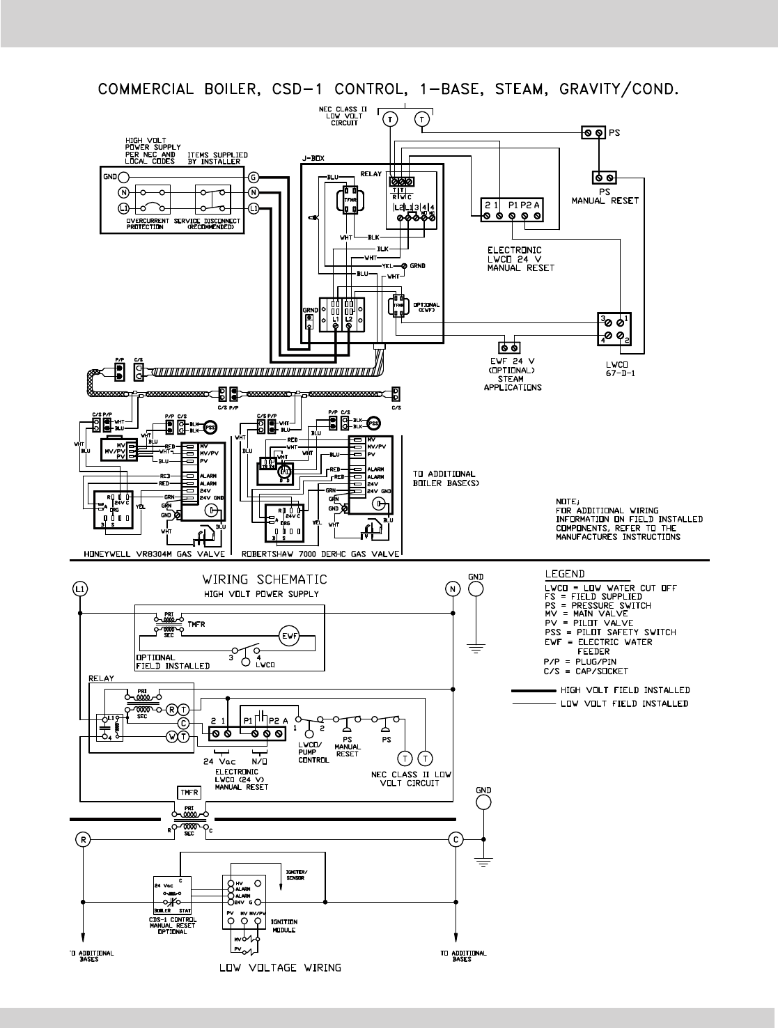
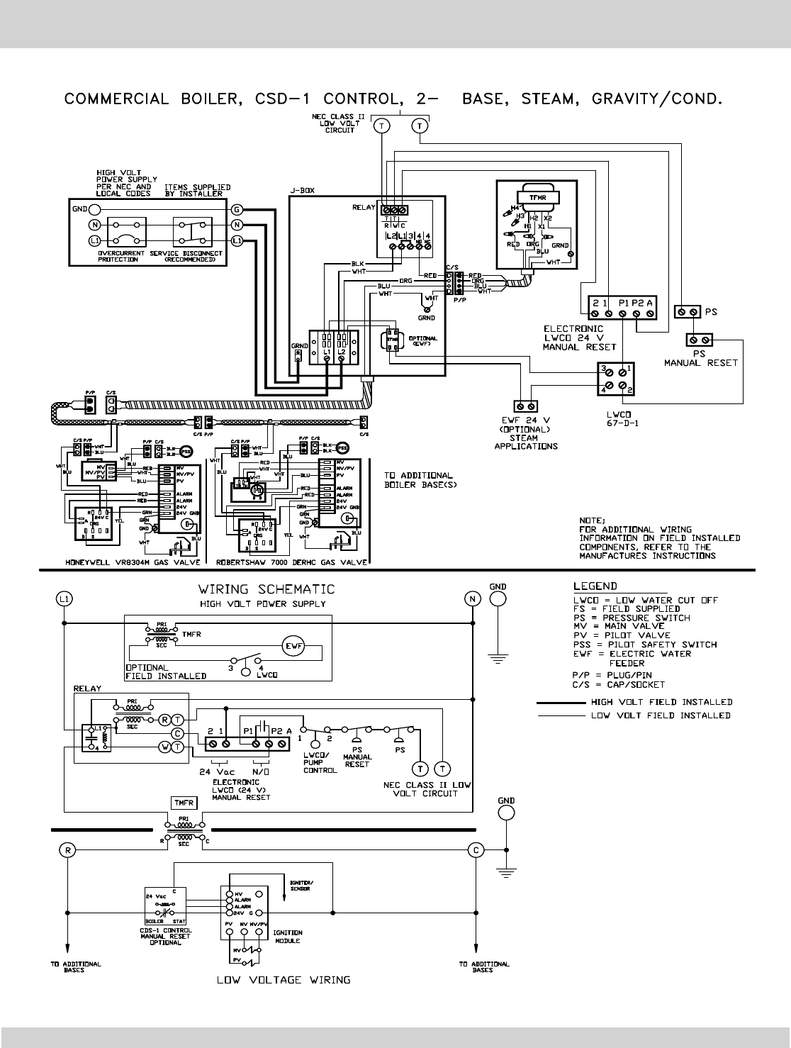
ELECTRICAL WIRE DIAGRAMS - CSD-1 STEAM BOILERS
WITH CONDENSATE PUMP/GRAVITY RETURN
11
3
ELECTRICAL WIRE DIAGRAMS - CSD-1 STEAM BOILERS
WITH CONDENSATE PUMP/GRAVITY RETURN
12
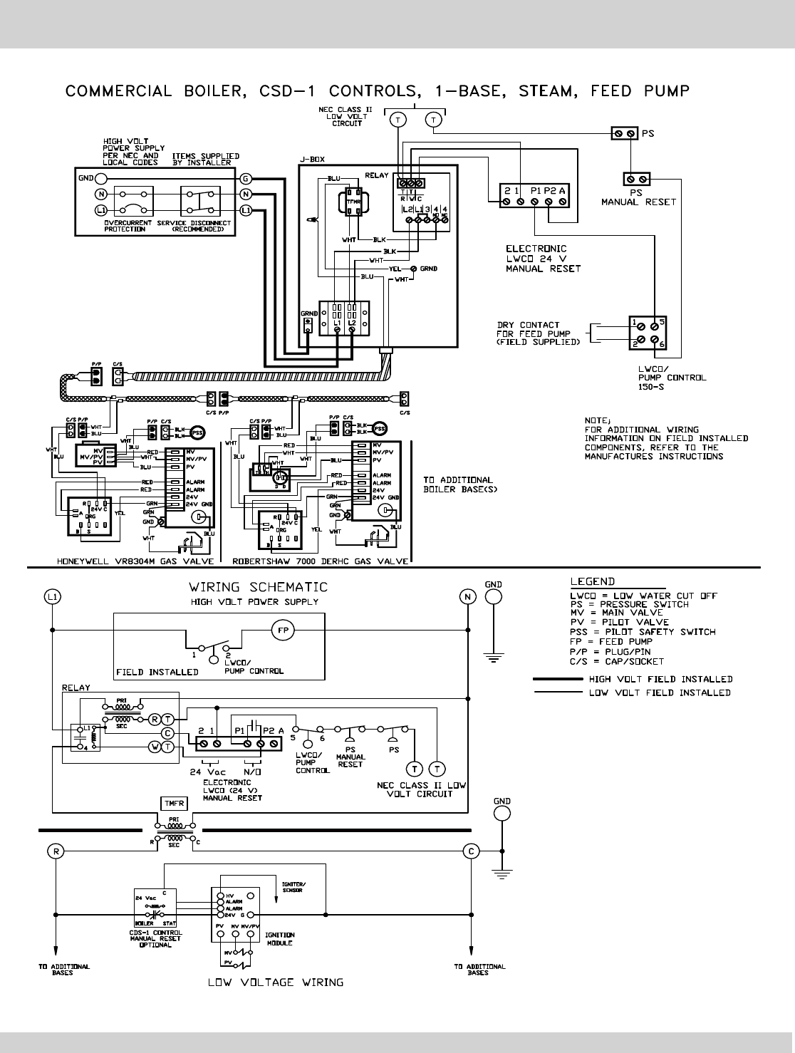
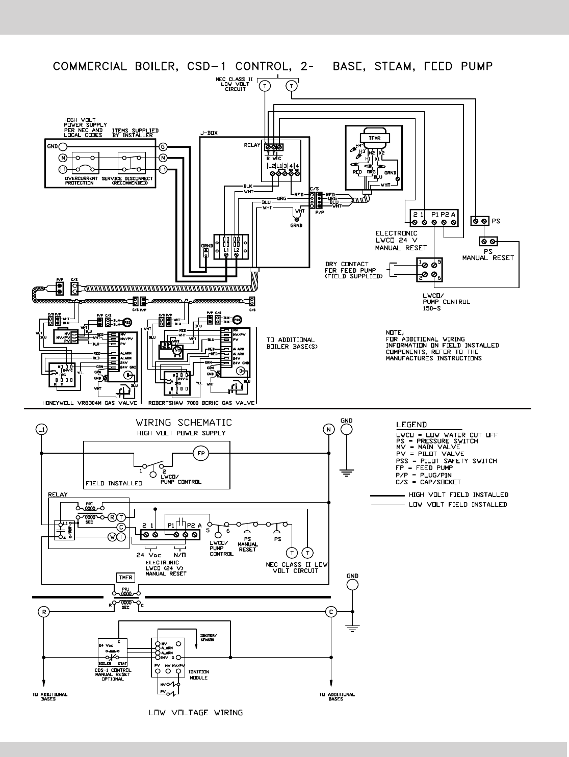
ELECTRICAL WIRE DIAGRAMS - CSD-1 STEAM BOILERS
WITH BOILER FEED PUMP RETURN
13
ELECTRICAL WIRE DIAGRAMS - CSD-1 STEAM BOILERS
WITH BOILER FEED PUMP RETURN
3
14

NOTES
15
