Utillighting ULBM-01 BT Module User Manual Approval Sheet
Utillighting Co.,Ltd. BT Module Approval Sheet
UserManual.wiki
>
Utillighting
>
ULBM 01 User Manual
User Manual
Navigation menu
Upload a User Manual
Namespaces
Wiki Guide
HTML
PDF
Info
Views
User Manual
Discussion / Help
Navigation
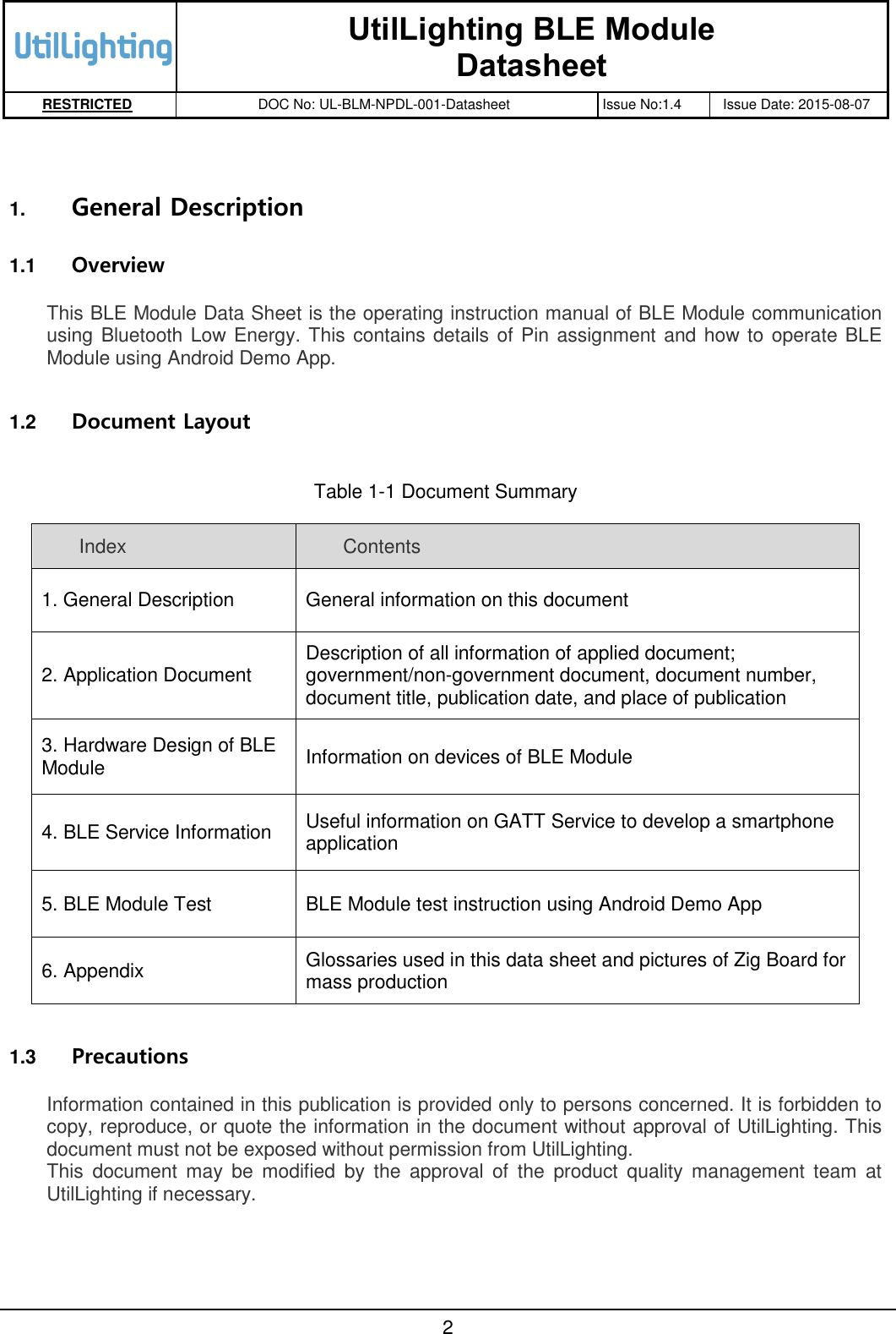
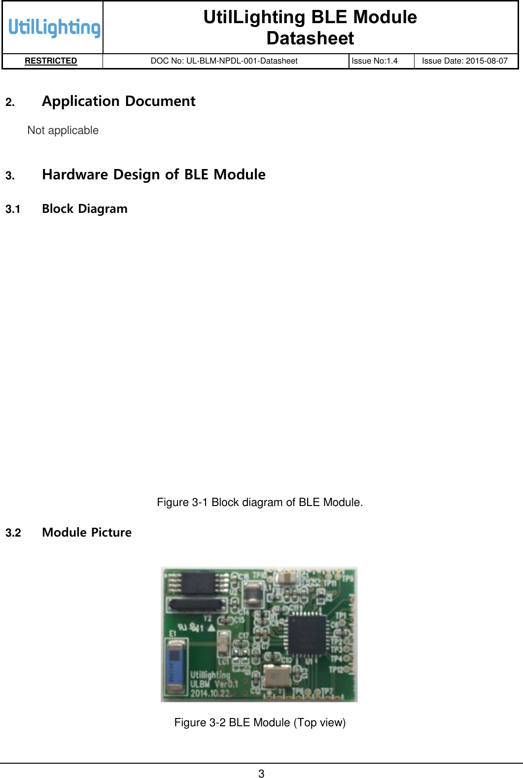
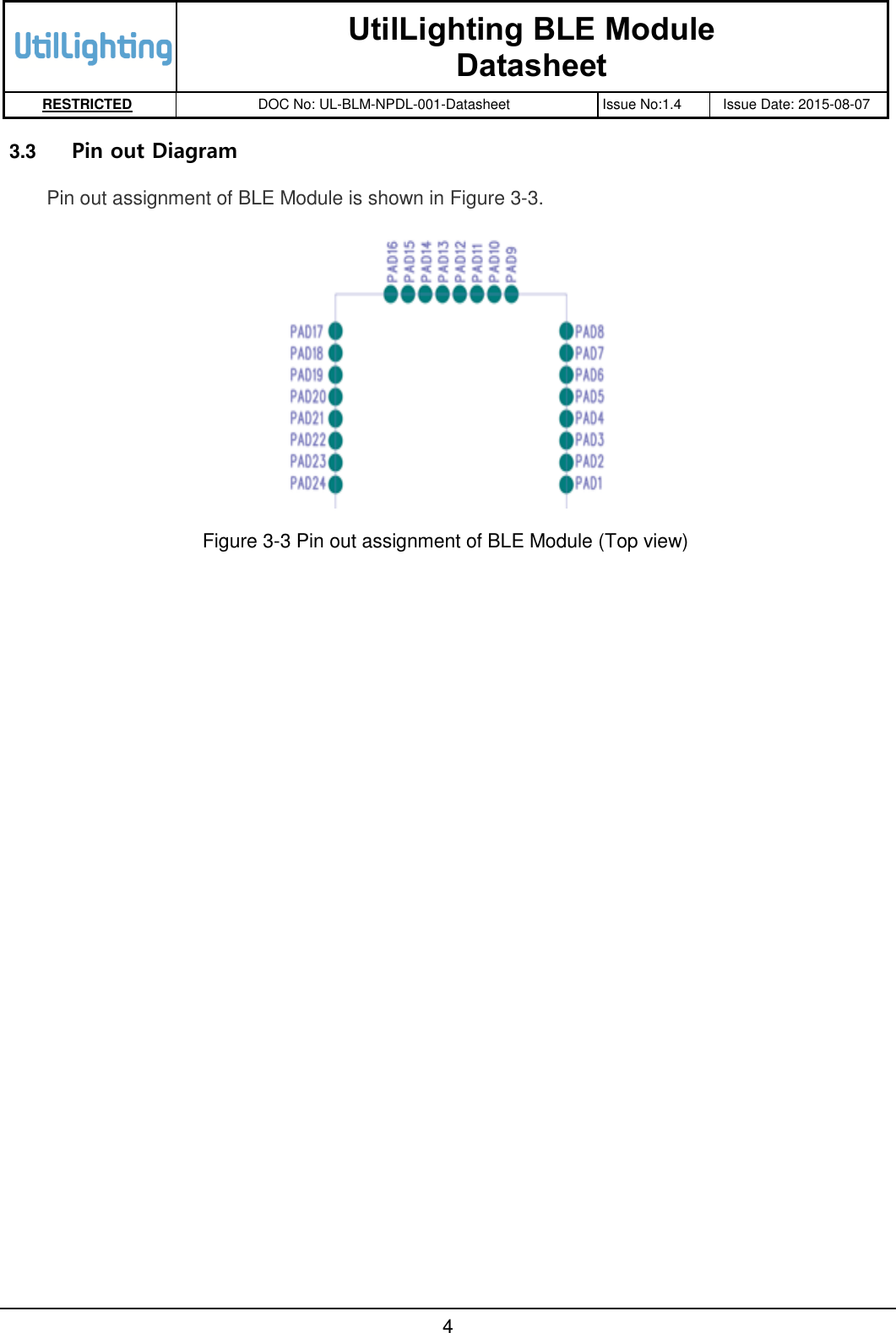
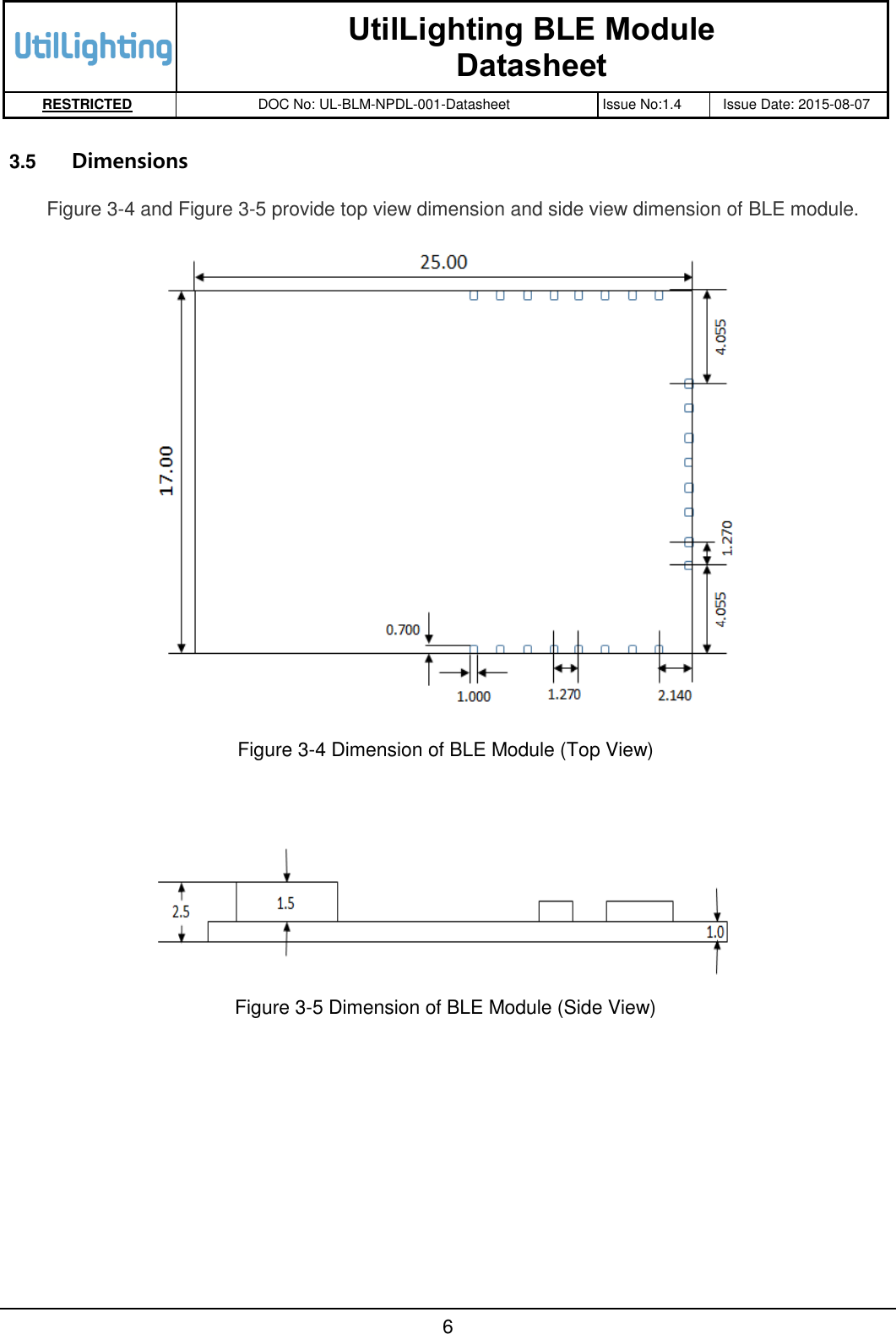
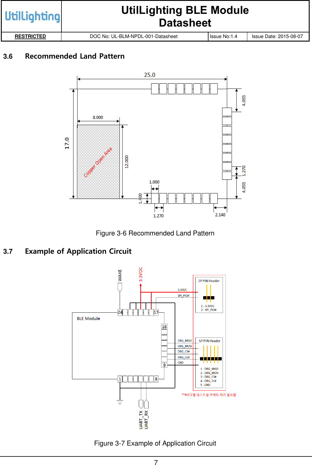
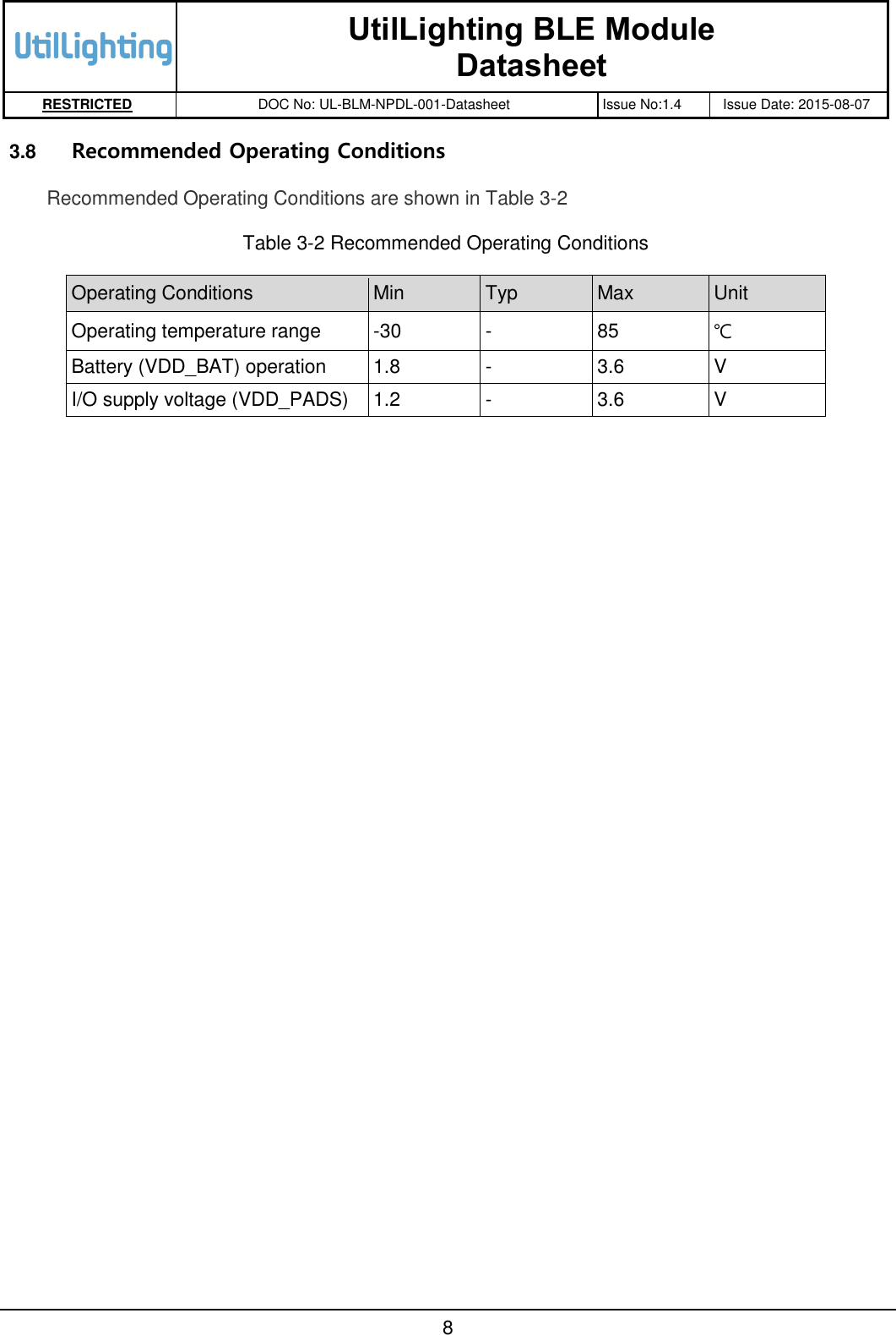
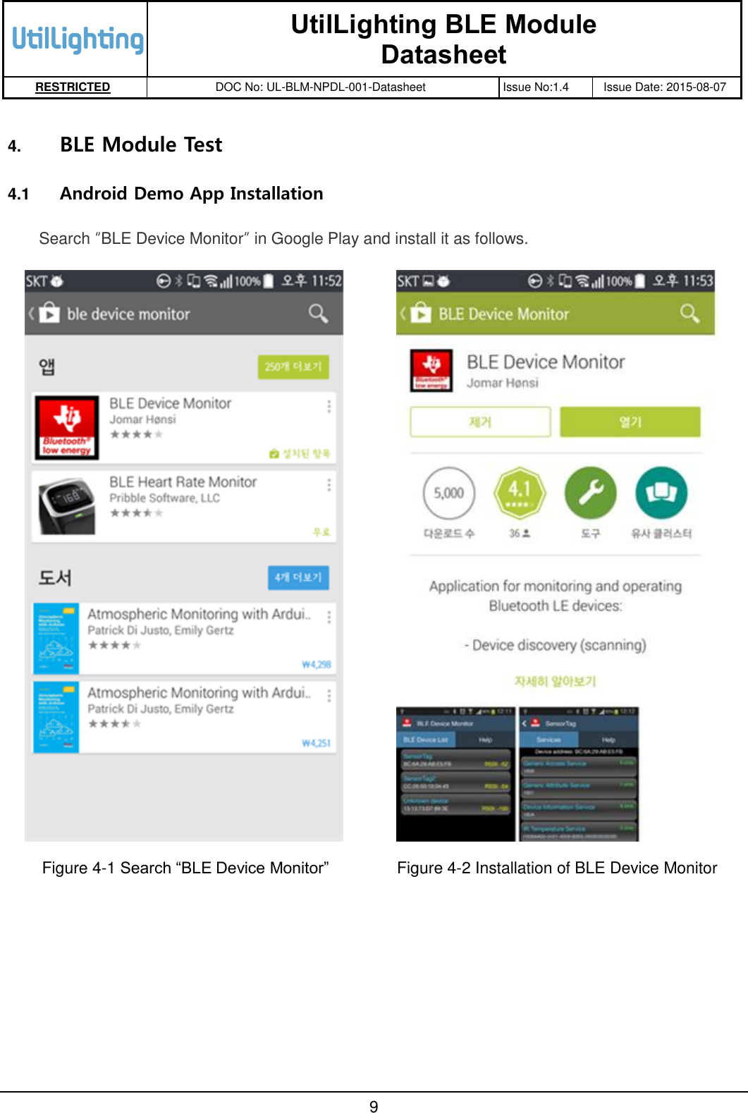
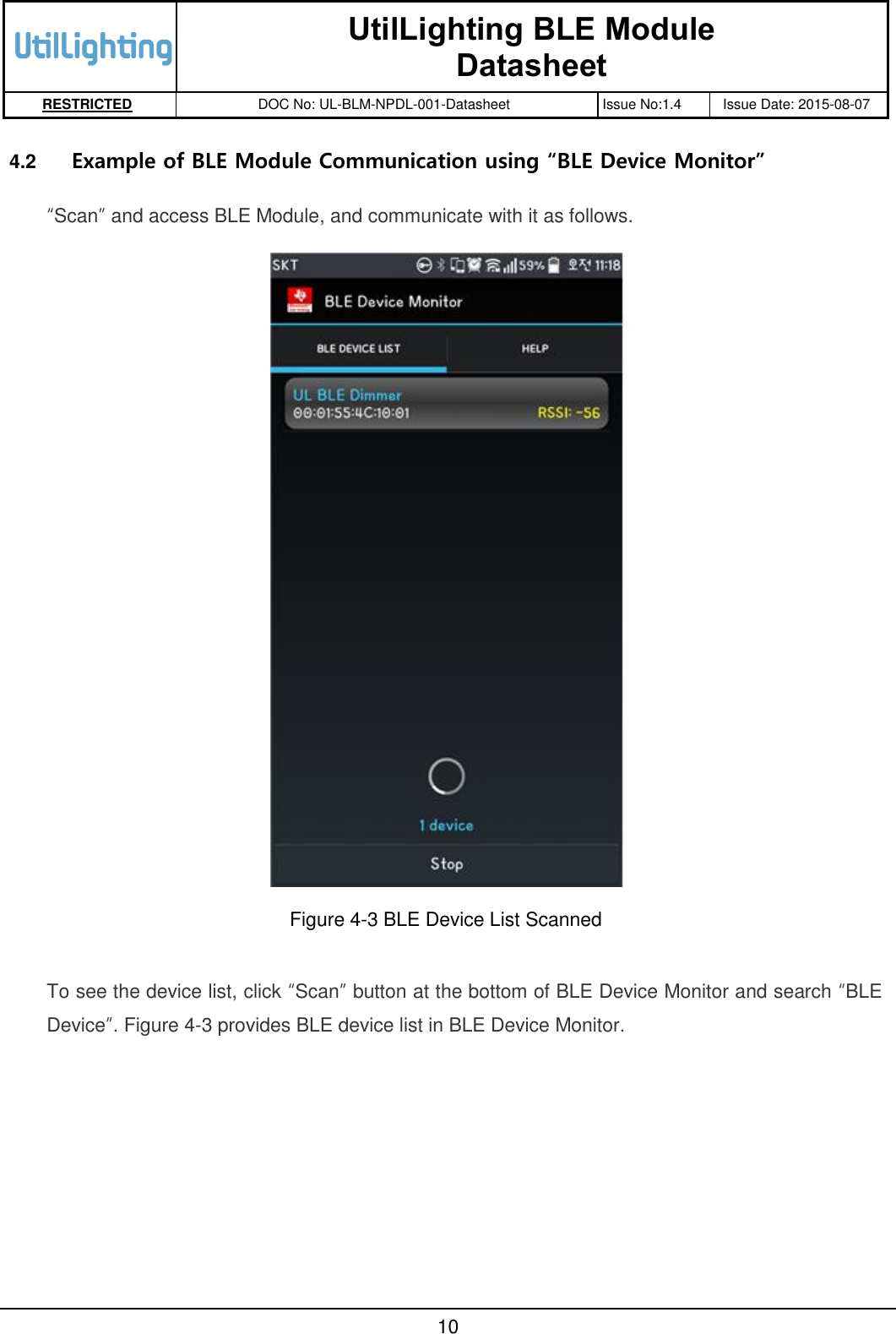
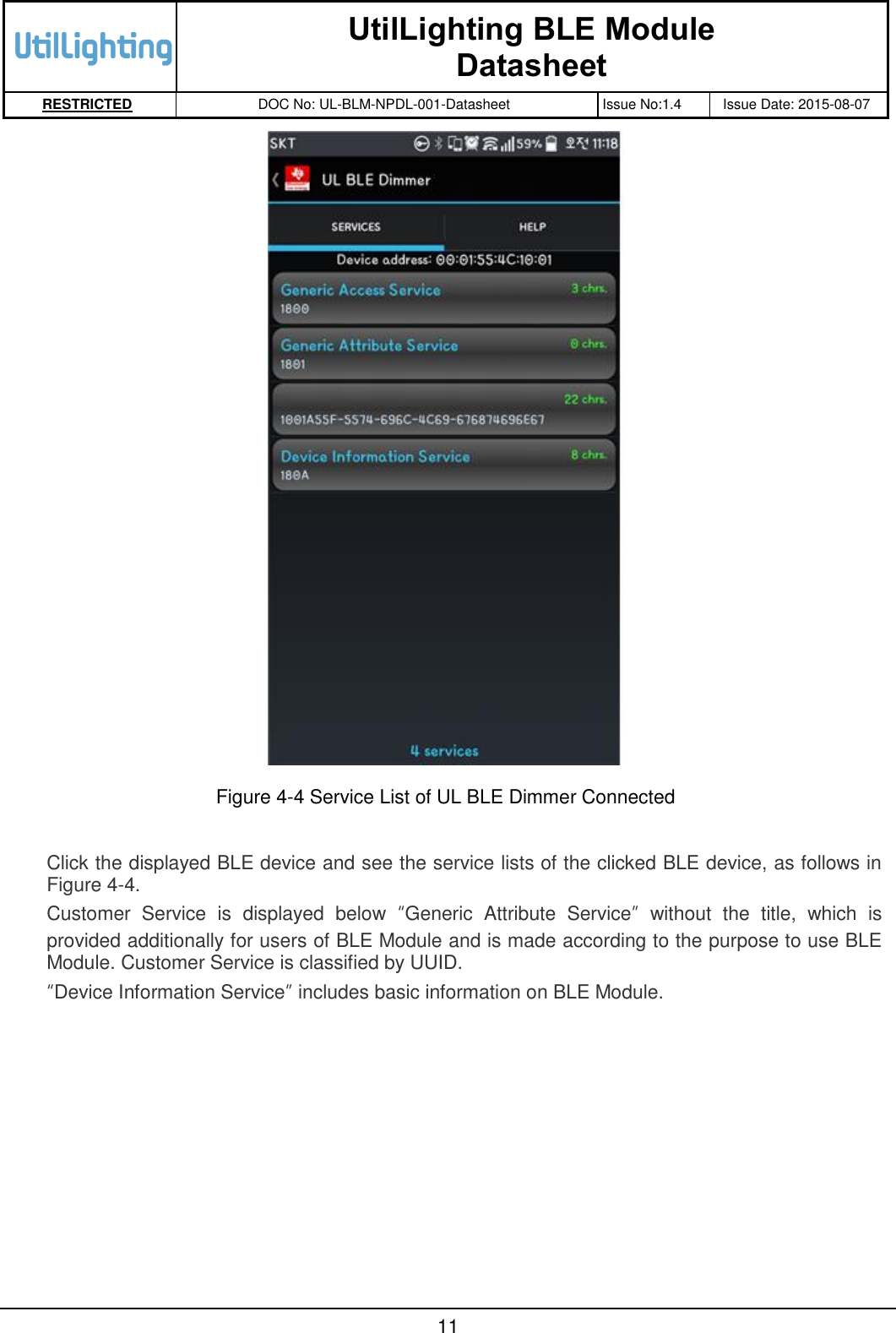
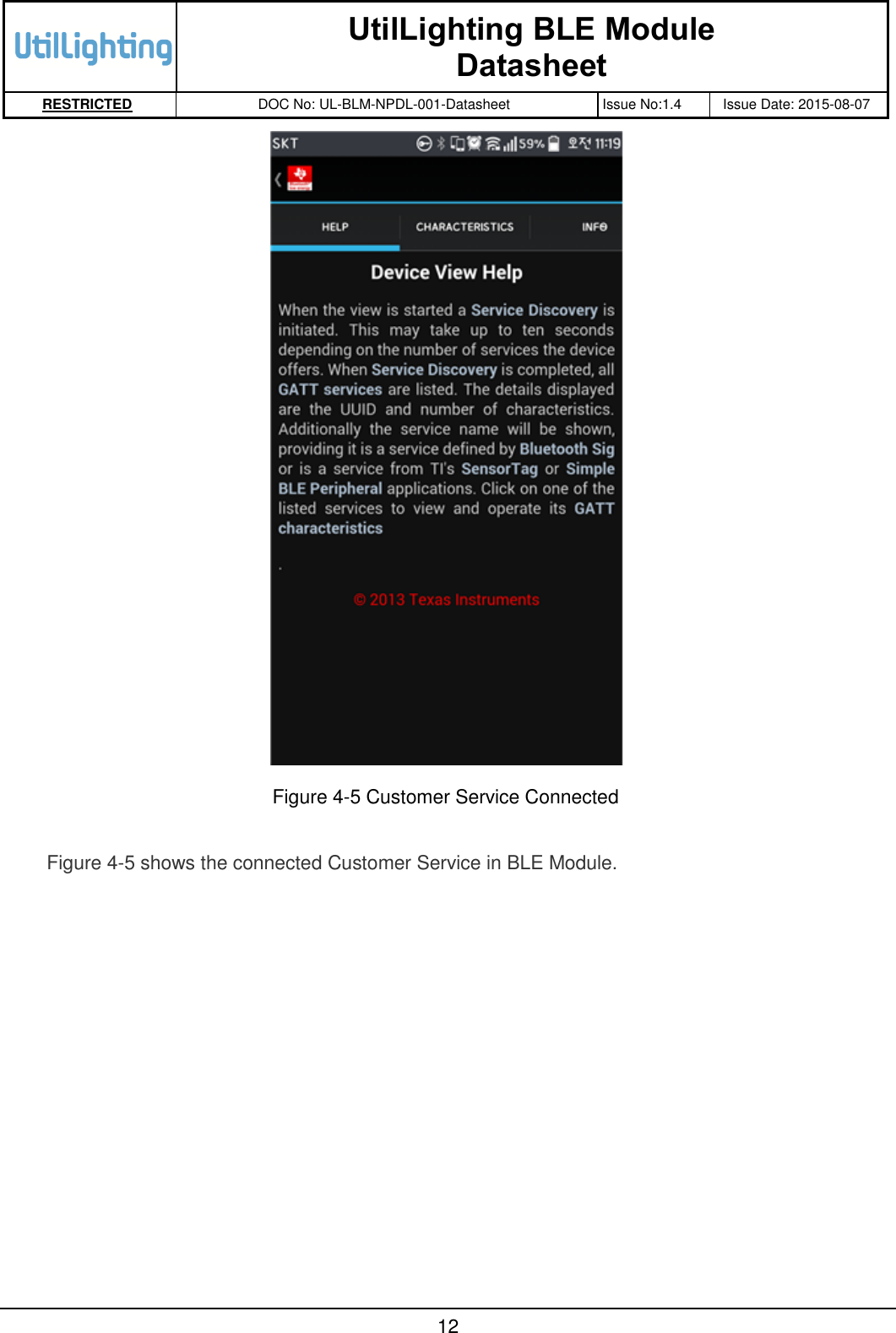
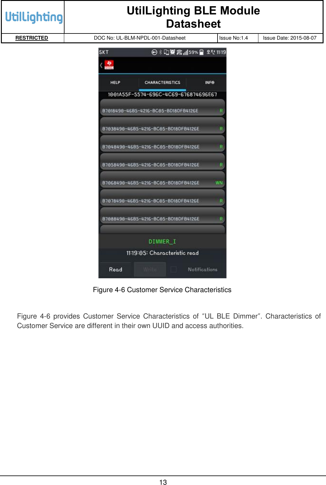
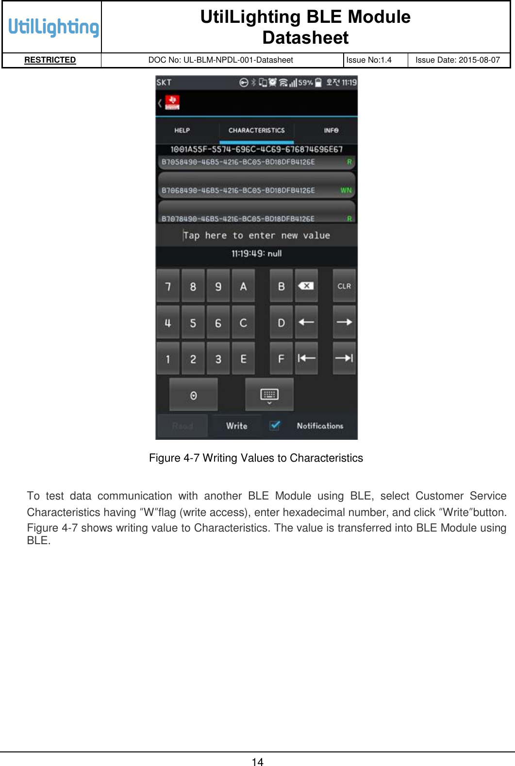
![UtilLighting BLE Module Datasheet RESTRICTED DOC No: UL-BLM-NPDL-001-Datasheet Issue No:1.4 Issue Date: 2015-08-07 5 3.4 Pin Description 오류! 참조 원본을 찾을 수 없습니다. provides pin descriptions for BLE Module. Table 3-1 Pin Description No Pin Name Description 1 GND Ground 2 AIO2 Analogue Programmable I/O #2 3 AIO1 Analogue Programmable I/O #1 4 AIO0 Analogue Programmable I/O #0 5 PIO0_UART_TX Programmable I/O #0 or UART TX 6 PIO1_UART_RX Programmable I/O #1 or UART RX 7 PIO3 Programmable I/O #3 8 PIO4 Programmable I/O #4 9 GND Ground 10 PIO5_DBG_CLK Programmable I/O #5 or Debug SPI CLK 11 PIO6_DBG_CS# Programmable I/O #6 or Debug SPI CS# 12 PIO7_DBG_MOSI Programmable I/O #7 or Debug SPI MOSI 13 PIO8_DBG_MISO Programmable I/O #8 or Debug SPI MISO 14 PIO9 Programmable I/O #9 15 PIO10 Programmable I/O #10 16 PIO11 Programmable I/O #11 17 SPI_PIO# Selects SPI debug on PIO[8:5] 18 VDD_PADS 3.3V DC input 19 GND Ground 20 VDD_BAT 3.3V DC input 21 GND Ground 22 GND Ground 23 N.C No Connected 24 WAKE Input to Wake Module](https://usermanual.wiki/Utillighting/ULBM-01/User-Guide-2726785-Page-9.png)