Utillighting ULBM-01 BT Module User Manual Approval Sheet
Utillighting Co.,Ltd. BT Module Approval Sheet
User Manual

Copyright © 2015 by UtilLighting. All Rights Reserved
Prior approval shall be obtained from UtilLighting in order to reproduce, copy or distribute this document.
UtilLighting BLE Module
Datasheet
Document No: UL-BLM-NPDL-001
Issue No: 1.4
Issue Date: 2015-08-07
UtilLighting
Seoul, Korea
http://www.UtilLighting.com
UtilLighting BLE Module
Datasheet
RESTRICTED
DOC No: UL-BLM-NPDL-001-Datasheet
Issue No:1.4
Issue Date: 2015-08-07
i
Document Revision History
Issue
No
Issue Date
Revised Part
/ Page
Reason for Revision
1.4
2015-08-07
Section 4
Delete sections
1.3
2015-07-14
Section 3
Section 7
Updates included
- Module picture added
- Recommended Land Pattern added
- Example Application Circuit added
1.2
2015-01-21
Section 3
Updates included
-Mass production of Zig Board version added
1.1
2014-11-21
Section 3
Updates included
-Section 3 and 5 changed
1.0
2015-07-14
-
Initial release of this document

UtilLighting BLE Module
Datasheet
RESTRICTED
DOC No: UL-BLM-NPDL-001-Datasheet
Issue No:1.4
Issue Date: 2015-08-07
ii
Index
1. General Description ...................................................................................................................... 2
1.1 Overview............................................................................................................................ 2
1.2 Document Layout ............................................................................................................... 2
1.3 Precautions ........................................................................................................................ 2
2. Application Document ................................................................................................................... 3
3. Hardware Design of BLE Module .................................................................................................. 3
3.1 Block Diagram ................................................................................................................... 3
3.2 Module Picture ................................................................................................................... 3
3.3 Pin out Diagram ................................................................................................................. 4
3.4 Pin Description .................................................................................................................. 5
3.5 Dimensions ........................................................................................................................ 6
3.6 Recommended Land Pattern ............................................................................................. 7
3.7 Example of Application Circuit ........................................................................................... 7
3.8 Recommended Operating Conditions ................................................................................ 8
4. BLE Module Test .......................................................................................................................... 9
4.1 Android Demo App Installation ........................................................................................... 9
4.2 Example of BLE Module Communication using “BLE Device Monitor” ............................. 10
5. Appendix .................................................................................................................................... 15
5.1 Abbreviation ..................................................................................................................... 15
5.2 Zig Board for Mass Production ......................................................................................... 15
6. Application .................................................................................................................................. 17
6.1 LED lighting system ......................................................................................................... 17
6.1.1 Description ........................................................................................................... 17
6.1.2 Features ............................................................................................................... 17
6.1.3 Specification ......................................................................................................... 18

UtilLighting BLE Module
Datasheet
RESTRICTED
DOC No: UL-BLM-NPDL-001-Datasheet
Issue No:1.4
Issue Date: 2015-08-07
iii
Figure
Figure 3-1 Block diagram of BLE Module. ............................................................................................ 3
Figure 3-2 BLE Module (Top view) ....................................................................................................... 3
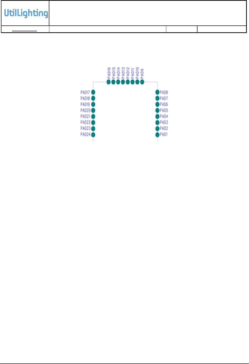
Figure 3-3 Pin out assignment of BLE Module (Top view) .................................................................... 4
Figure 3-4 Dimension of BLE Module (Top View)................................................................................. 6
Figure 3-5 Dimension of BLE Module (Side View)................................................................................ 6
Figure 3-6 Recommended Land Pattern .............................................................................................. 7
Figure 3-7 Example of Application Circuit ............................................................................................ 7
Figure 4-1 Search “BLE Device Monitor” .............................................................................................. 9
Figure 4-2 Installation of BLE Device Monitor ...................................................................................... 9
Figure 4-3 BLE Device List Scanned.................................................................................................. 10
Figure 4-4 Service List of UL BLE Dimmer Connected ....................................................................... 11
Figure 4-5 Customer Service Connected ........................................................................................... 12
Figure 4-6 Customer Service Characteristics ..................................................................................... 13
Figure 4-7 Writing Values to Characteristics ...................................................................................... 14
Figure 5-1 Zig Board for Mass Production (1) .................................................................................... 15
Figure 5-2 Zig Board for Mass Production (2) .................................................................................... 16
Figure 6-1 LED lighting System .......................................................................................................... 17
Table
Table 1-1 Document Summary ............................................................................................................ 2
Table 3-1 Pin Description ..................................................................................................................... 5
Table 3-2 Recommended Operating Conditions .................................................................................. 8
Table 5-1 Abbreviations ..................................................................................................................... 15
Table 6-1 Specification for LED lighting System ................................................................................. 18
UtilLighting BLE Module
Datasheet
RESTRICTED
DOC No: UL-BLM-NPDL-001-Datasheet
Issue No:1.4
Issue Date: 2015-08-07
1
Features
Bluetooth v4.1 specification compliant ; Bluetooth Smart ; Bluetooth Low Energy ;
BLE
Small: 17mm x 25mm
Integrated chip antenna
RSSI monitoring for proximity applications
<900nA current consumption in dormant mode
<20mA peak current consumption in RX active
Programmable general purpose PIO controller
10-bit ADC
12 digital PIOs
3 analog AIOs
1 UART
shared 1 I2C(only master) or 1 SPI(master/slave)
4 PWM modules
Wake-up interrupt and watchdog timer
5 operating modes : Running, Idle, Deep sleep, Hibernate, Dormant
Over-the-Air Configuration or Firmware Update service (by Smart-phone)
UtilLighting BLE Module
UtilLighting BLE Module
Datasheet
RESTRICTED
DOC No: UL-BLM-NPDL-001-Datasheet
Issue No:1.4
Issue Date: 2015-08-07
2
1. General Description
1.1 Overview
This BLE Module Data Sheet is the operating instruction manual of BLE Module communication
using Bluetooth Low Energy. This contains details of Pin assignment and how to operate BLE
Module using Android Demo App.
1.2 Document Layout
Table 1-1 Document Summary
Index
Contents
1. General Description
General information on this document
2. Application Document
Description of all information of applied document;
government/non-government document, document number,
document title, publication date, and place of publication
3. Hardware Design of BLE
Module
Information on devices of BLE Module
4. BLE Service Information
Useful information on GATT Service to develop a smartphone
application
5. BLE Module Test
BLE Module test instruction using Android Demo App
6. Appendix
Glossaries used in this data sheet and pictures of Zig Board for
mass production
1.3 Precautions
Information contained in this publication is provided only to persons concerned. It is forbidden to
copy, reproduce, or quote the information in the document without approval of UtilLighting. This
document must not be exposed without permission from UtilLighting.
This document may be modified by the approval of the product quality management team at
UtilLighting if necessary.
UtilLighting BLE Module
Datasheet
RESTRICTED
DOC No: UL-BLM-NPDL-001-Datasheet
Issue No:1.4
Issue Date: 2015-08-07
3
2. Application Document
Not applicable
3. Hardware Design of BLE Module
3.1 Block Diagram
Figure 3-1 Block diagram of BLE Module.
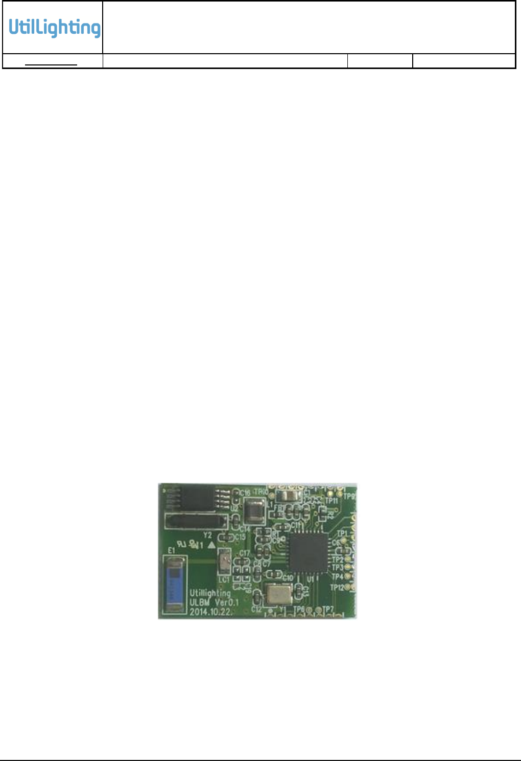
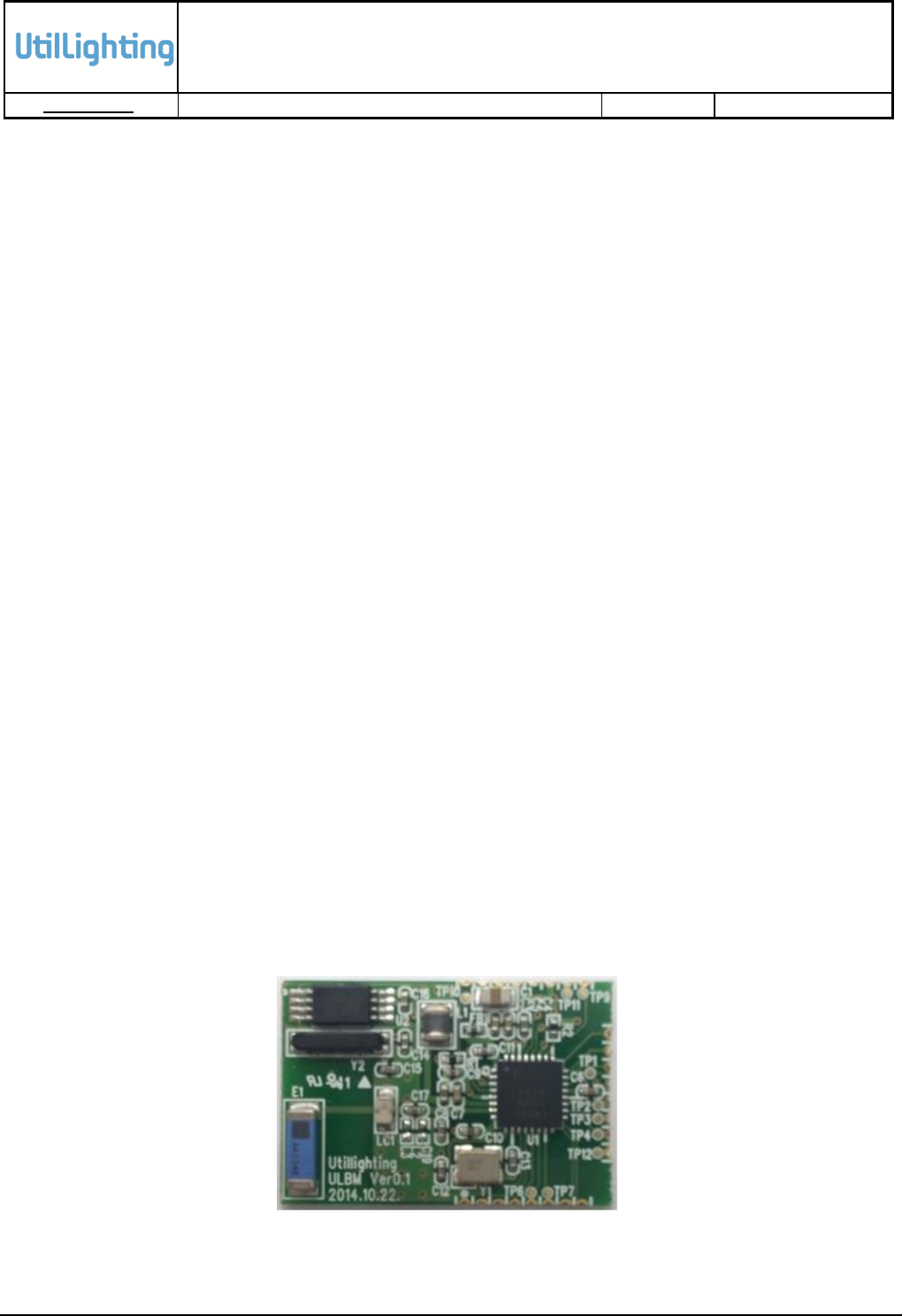
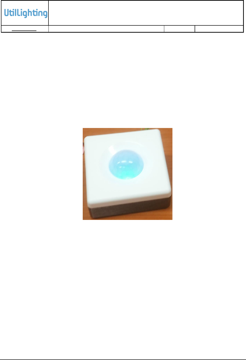
3.2 Module Picture
Figure 3-2 BLE Module (Top view)
UtilLighting BLE Module
Datasheet
RESTRICTED
DOC No: UL-BLM-NPDL-001-Datasheet
Issue No:1.4
Issue Date: 2015-08-07
5
3.4 Pin Description
오류! 참조 원본을 찾을 수 없습니다. provides pin descriptions for BLE Module.
Table 3-1 Pin Description
No
Pin Name
Description
1
GND
Ground
2
AIO2
Analogue Programmable I/O #2
3
AIO1
Analogue Programmable I/O #1
4
AIO0
Analogue Programmable I/O #0
5
PIO0_UART_TX
Programmable I/O #0 or UART TX
6
PIO1_UART_RX
Programmable I/O #1 or UART RX
7
PIO3
Programmable I/O #3
8
PIO4
Programmable I/O #4
9
GND
Ground
10
PIO5_DBG_CLK
Programmable I/O #5 or Debug SPI CLK
11
PIO6_DBG_CS#
Programmable I/O #6 or Debug SPI CS#
12
PIO7_DBG_MOSI
Programmable I/O #7 or Debug SPI MOSI
13
PIO8_DBG_MISO
Programmable I/O #8 or Debug SPI MISO
14
PIO9
Programmable I/O #9
15
PIO10
Programmable I/O #10
16
PIO11
Programmable I/O #11
17
SPI_PIO#
Selects SPI debug on PIO[8:5]
18
VDD_PADS
3.3V DC input
19
GND
Ground
20
VDD_BAT
3.3V DC input
21
GND
Ground
22
GND
Ground
23
N.C
No Connected
24
WAKE
Input to Wake Module
UtilLighting BLE Module
Datasheet
RESTRICTED
DOC No: UL-BLM-NPDL-001-Datasheet
Issue No:1.4
Issue Date: 2015-08-07
6
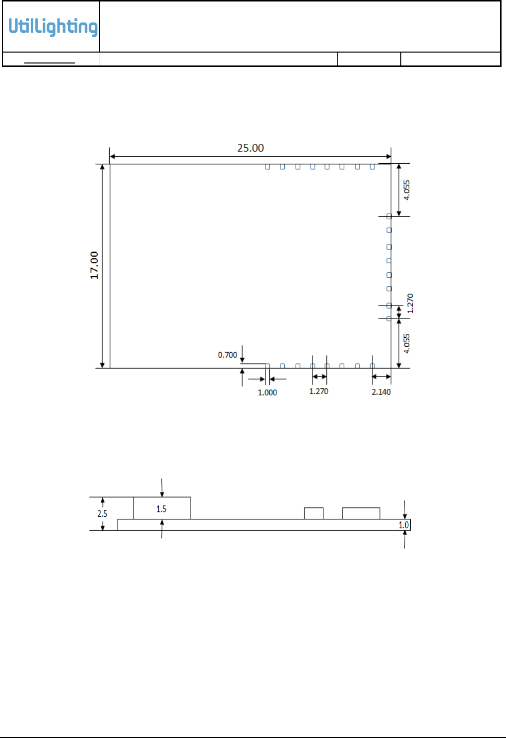
3.5 Dimensions
Figure 3-4 and Figure 3-5 provide top view dimension and side view dimension of BLE module.
Figure 3-4 Dimension of BLE Module (Top View)
Figure 3-5 Dimension of BLE Module (Side View)
UtilLighting BLE Module
Datasheet
RESTRICTED
DOC No: UL-BLM-NPDL-001-Datasheet
Issue No:1.4
Issue Date: 2015-08-07
7
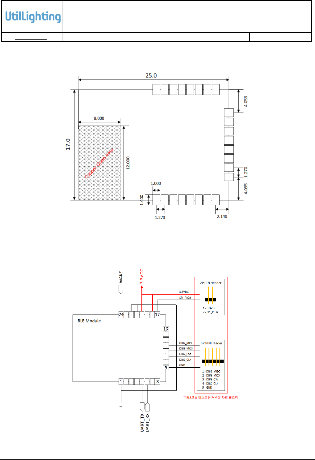
3.6 Recommended Land Pattern
Figure 3-6 Recommended Land Pattern
3.7 Example of Application Circuit
Figure 3-7 Example of Application Circuit
UtilLighting BLE Module
Datasheet
RESTRICTED
DOC No: UL-BLM-NPDL-001-Datasheet
Issue No:1.4
Issue Date: 2015-08-07
8
3.8 Recommended Operating Conditions
Recommended Operating Conditions are shown in Table 3-2
Table 3-2 Recommended Operating Conditions
Operating Conditions
Min
Typ
Max
Unit
Operating temperature range
-30
-
85
℃
Battery (VDD_BAT) operation
1.8
-
3.6
V
I/O supply voltage (VDD_PADS)
1.2
-
3.6
V
UtilLighting BLE Module
Datasheet
RESTRICTED
DOC No: UL-BLM-NPDL-001-Datasheet
Issue No:1.4
Issue Date: 2015-08-07
9
4. BLE Module Test
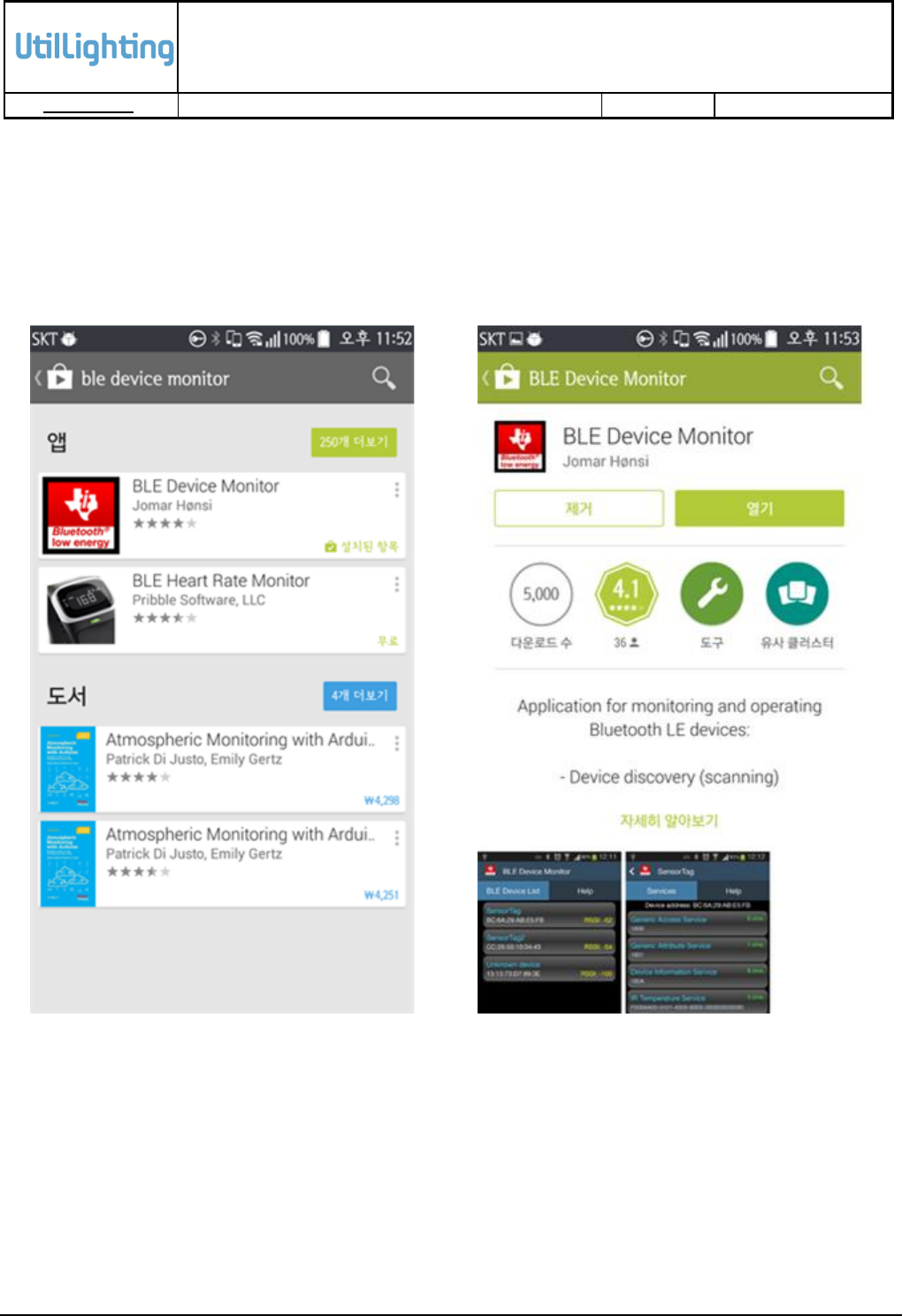
4.1 Android Demo App Installation
Search “BLE Device Monitor” in Google Play and install it as follows.
Figure 4-1 Search “BLE Device Monitor”
Figure 4-2 Installation of BLE Device Monitor
UtilLighting BLE Module
Datasheet
RESTRICTED
DOC No: UL-BLM-NPDL-001-Datasheet
Issue No:1.4
Issue Date: 2015-08-07
10
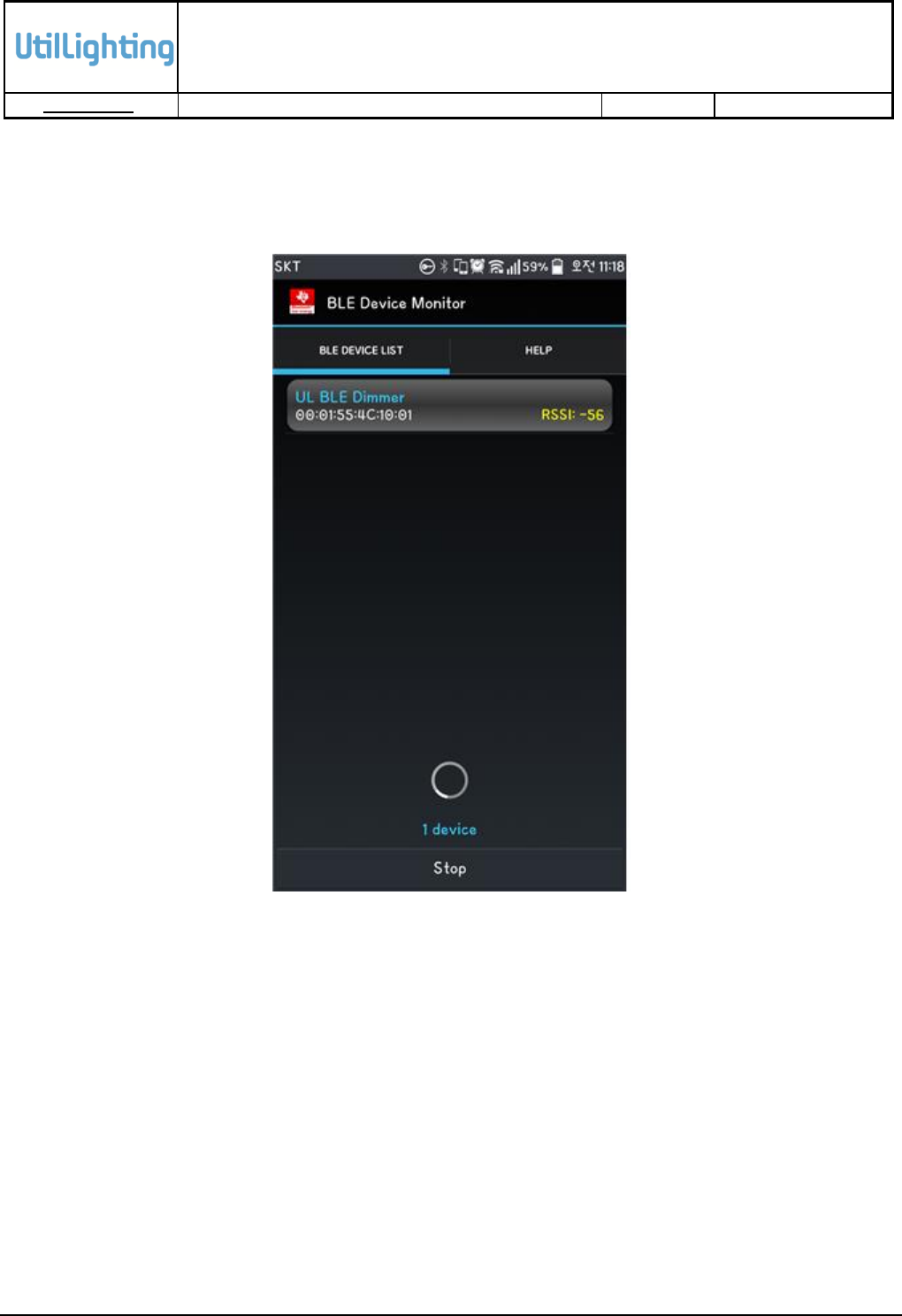
4.2 Example of BLE Module Communication using “BLE Device Monitor”
“Scan” and access BLE Module, and communicate with it as follows.
Figure 4-3 BLE Device List Scanned
To see the device list, click “Scan” button at the bottom of BLE Device Monitor and search “BLE
Device”. Figure 4-3 provides BLE device list in BLE Device Monitor.
UtilLighting BLE Module
Datasheet
RESTRICTED
DOC No: UL-BLM-NPDL-001-Datasheet
Issue No:1.4
Issue Date: 2015-08-07
11
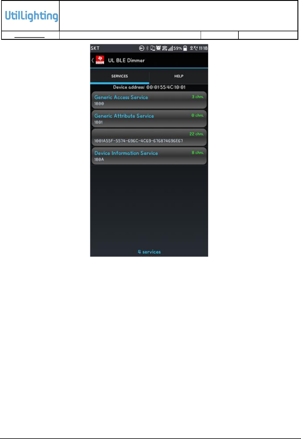
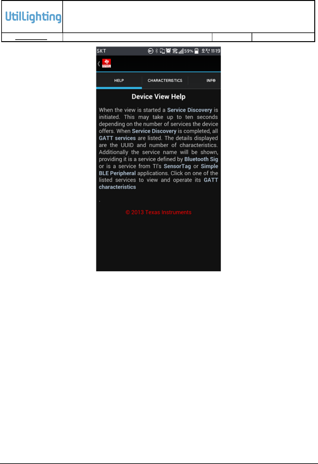
Figure 4-4 Service List of UL BLE Dimmer Connected
Click the displayed BLE device and see the service lists of the clicked BLE device, as follows in
Figure 4-4.
Customer Service is displayed below “Generic Attribute Service” without the title, which is
provided additionally for users of BLE Module and is made according to the purpose to use BLE
Module. Customer Service is classified by UUID.
“Device Information Service” includes basic information on BLE Module.
UtilLighting BLE Module
Datasheet
RESTRICTED
DOC No: UL-BLM-NPDL-001-Datasheet
Issue No:1.4
Issue Date: 2015-08-07
13
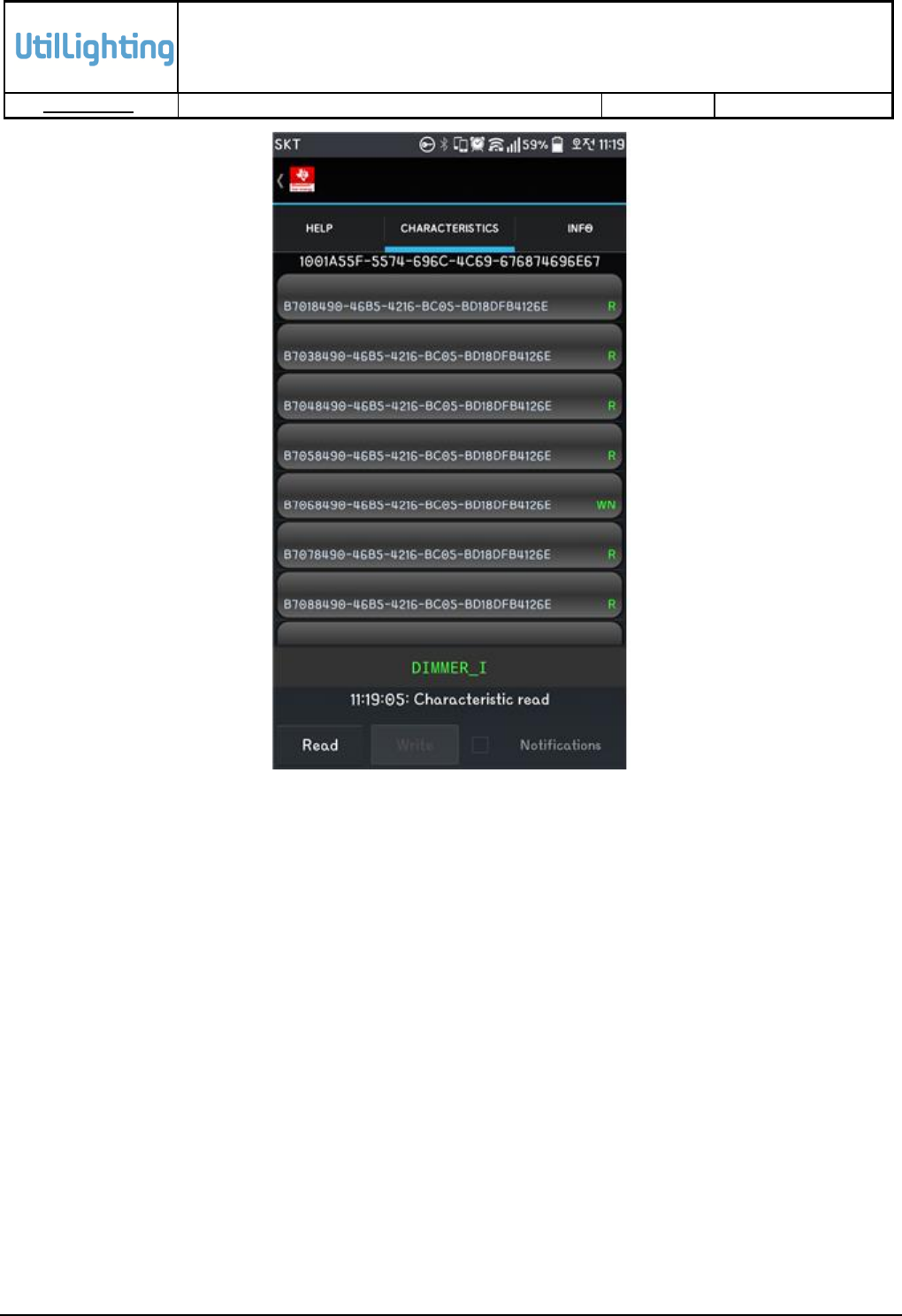
Figure 4-6 Customer Service Characteristics
Figure 4-6 provides Customer Service Characteristics of “UL BLE Dimmer”. Characteristics of
Customer Service are different in their own UUID and access authorities.
UtilLighting BLE Module
Datasheet
RESTRICTED
DOC No: UL-BLM-NPDL-001-Datasheet
Issue No:1.4
Issue Date: 2015-08-07
14
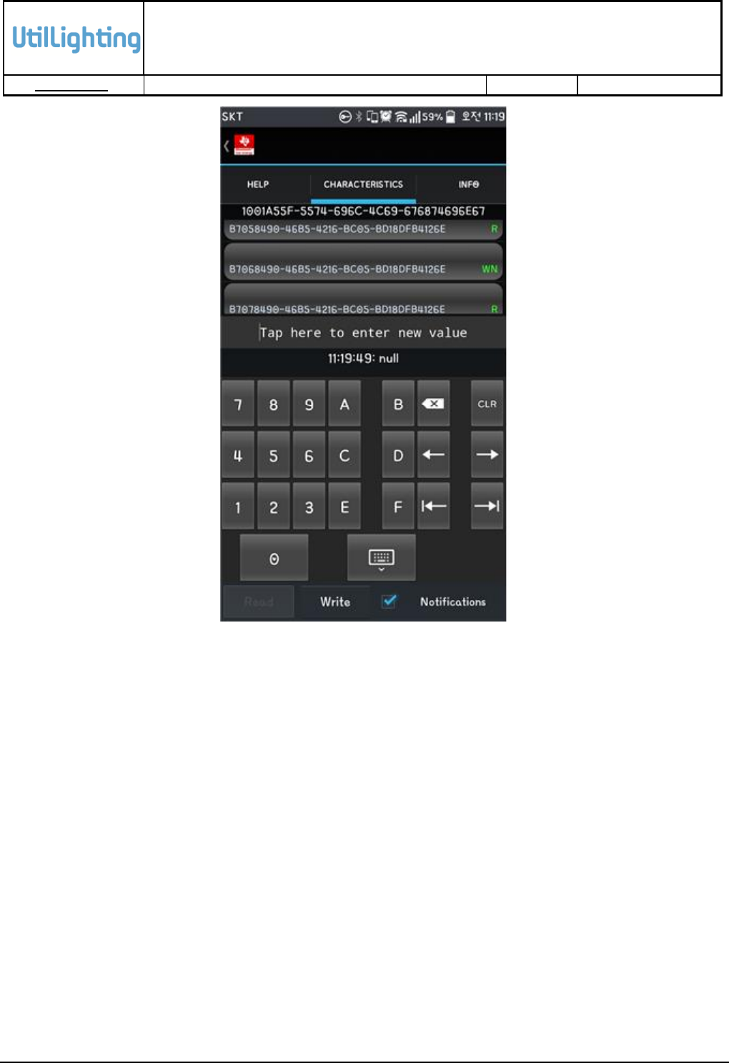
Figure 4-7 Writing Values to Characteristics
To test data communication with another BLE Module using BLE, select Customer Service
Characteristics having “W”flag (write access), enter hexadecimal number, and click “Write”button.
Figure 4-7 shows writing value to Characteristics. The value is transferred into BLE Module using
BLE.
UtilLighting BLE Module
Datasheet
RESTRICTED
DOC No: UL-BLM-NPDL-001-Datasheet
Issue No:1.4
Issue Date: 2015-08-07
15
5. Appendix
5.1 Abbreviation
Table 5-1 provides abbreviations used in this document.
Table 5-1 Abbreviations
Term
Description
BLE
Bluetooth Low Energy
CSR
Cambridge Silicon Radio
DIM
Dimmer
DRD
Develmpment Related Documnet, which related development
NPDL
Non-Planned Documents List, which is not planned for project
management.
OTA
Over The Air; which are management modules for software
configuration and update using wireless communication.
PDL
Planned Documents List, which is planned for project management
UART
Universal Asynchronous Receiver/Transmitter
USART
Universal Synchronous and Asynchronous serial Receiver and
Transmitter
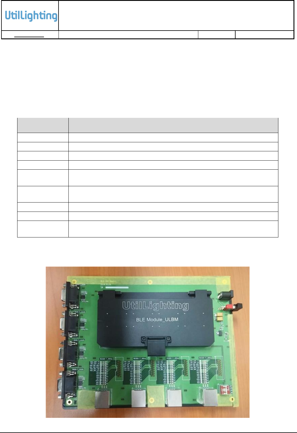
5.2 Zig Board for Mass Production
Figure 5-1 Zig Board for Mass Production (1)

UtilLighting BLE Module
Datasheet
RESTRICTED
DOC No: UL-BLM-NPDL-001-Datasheet
Issue No:1.4
Issue Date: 2015-08-07
16
Figure 5-2 Zig Board for Mass Production (2)
UtilLighting BLE Module
Datasheet
RESTRICTED
DOC No: UL-BLM-NPDL-001-Datasheet
Issue No:1.4
Issue Date: 2015-08-07
17
6. Application
6.1 LED lighting system
6.1.1 Description
LED lighting system which automatically adjusts preset illuminance of each LED light through
detecting the illuminance around each light can reduce electricity charge up to averagely 75%
compared to fluorescent lights. In addition, LED lighting system doesn’t need to have any
additional equipment separately for the network communication and all the functions of LED
lighting system can be easily controlled by only remote control.
Figure 6-1 LED lighting System
6.1.2 Features
Motion & light sensor
Network communication by Infrared without additional devices
Easy replacement by retrofit installation
Maximum brightness with minimal Unified Glare Rating(UGR)
Lighting product made in Korea
Life to 70% lumen maintenance – 50,000 hours / 5 Years warranty
Remarkable energy saving – 70%
100-277VAC / 40W Dimming / PF > 0.9 / CRI > 80 / CCT 5300K 4000K 3000K 2700K
UtilLighting BLE Module
Datasheet
RESTRICTED
DOC No: UL-BLM-NPDL-001-Datasheet
Issue No:1.4
Issue Date: 2015-08-07
18
6.1.3 Specification
Table 6-1 Specification for LED lighting System
Model No.
Control Mode
CCT
Power
Consumption
Input Voltage
Power
Efficiency
JUIDPL-S40-CZ
Remote Control
5000K
40W
AC100-277V
>0.9
JUIDPL-S40-NZ
Remote Control
4000K
40W
AC100-277V
>0.9
JUIDPL-S40-WZ
Remote Control
3000K
40W
AC100-277V
>0.9
JUIDPL-S40-WWZ
Remote Control
2700K
40W
AC100-277V
>0.9
UtilLighting BLE Module
Datasheet
RESTRICTED
DOC No: UL-BLM-NPDL-001-Datasheet
Issue No:1.4
Issue Date: 2015-08-07
19
FCC ID : 2AFNU-ULBM-01
This device complies with part 15 of the FCC Rules. Operation is subject to the following two
conditions: (1) This device may not cause harmful interference, and (2) this device must accept any
interference received, including interference that may cause undesired operation.
Note : This equipment has been tested and found to comply with the limits for a Class B digital device,
pursuant to Part 15 of FCC Rules. These limits are designed to provide reasonable protection against
harmful interference in a residential installation. This equipment generates, uses, and can radiate
radio frequency energy and, if not installed and used in accordance with the instructions, may cause
harmful interference to radio communications. However, there is no guarantee that interference will
not occur in a particular installation.
If this equipment does cause harmful interference to radio or television reception, which can be
determined by tuning the equipment off and on, the user is encouraged to try and correct the
interference by one or more of the following measures:
Reorient or relocate the receiving antenna.
Increase the distance between the equipment and the receiver.
Connect the equipment to outlet on a circuit different from that to which the receiver is
connected.
Consult the dealer or an experienced radio/TV technician for help.
Caution : Any changes or modifications in construction of this device which are not expressly
approved by the party responsible for compliance could void the user’s authority to operate the
equipment.
Warning
This equipment should be installed and operated with separation distance of at
least 20 cm from all persons.
Do not simultaneously emit.
UtilLighting BLE Module
Datasheet
RESTRICTED DOC No: UL-BLM-NPDL-001-Datasheet Issue No:1.4 Issue Date: 2015-08-07
20
Module Integration Instructions
This module has been granted modular approval for mobile applications. OEM integrators for host
products may use the module in their final products without additional FCC certification if they meet
the following conditions. Otherwise, additional FCC approvals must be obtained.
The host product with the module installed must be evaluated for simultaneous transmission
requirements.
The user manual for the host product must clearly indicate the operating requirements and
conditions that must be observed to ensure compliance with current FCC RF exposure
guidelines.
To comply with FCC regulations limiting both maximum RF output power and human exposure
to RF radiation, the maximum antenna gain including cable loss in a mobile-only exposure
condition must not exceed. Chip antenna, Max. gain:3.5 dBi
A label must be affixed to the outside of the host product with the following statements:
Contains FCCID: 2AFNU-ULBM-01
The final host / module combination may also need to be evaluated against the FCC Part 15B criteria
for unintentional radiators in order to be properly authorized for operation as a Part 15 digital device.
If the final host / module combination is intended for use as a portable device (see classifications
below) the host manufacturer is responsible for separate approvals for the SAR requirements from
FCC Part 2.1093 and RSS-102.