VEGA Americas PULS40 Fluid Level Radar Transmitter User Manual BA PULS5K D 1099
VEGA Americas Inc. Fluid Level Radar Transmitter BA PULS5K D 1099
UserManual.wiki
>
VEGA Americas
>
PULS40 User Manual
manual
Navigation menu
Upload a User Manual
Namespaces
Wiki Guide
HTML
PDF
Info
Views
User Manual
Discussion / Help
Navigation
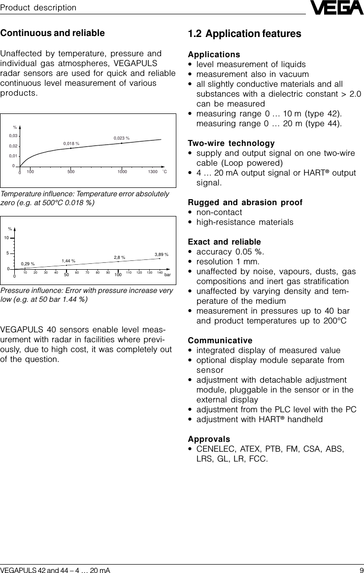
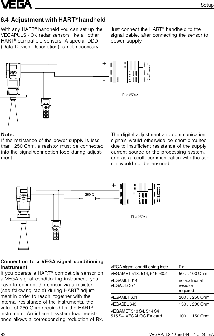
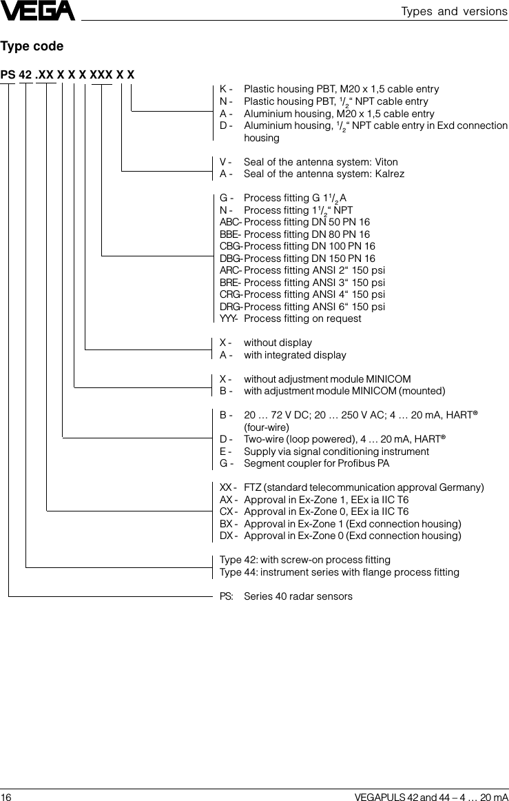
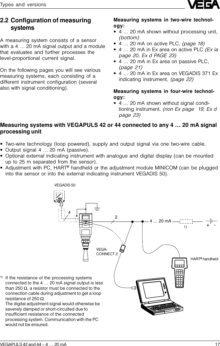
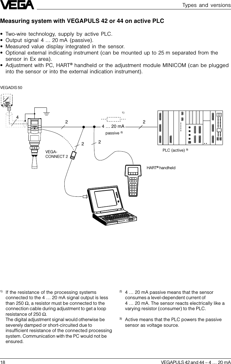
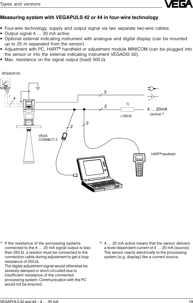
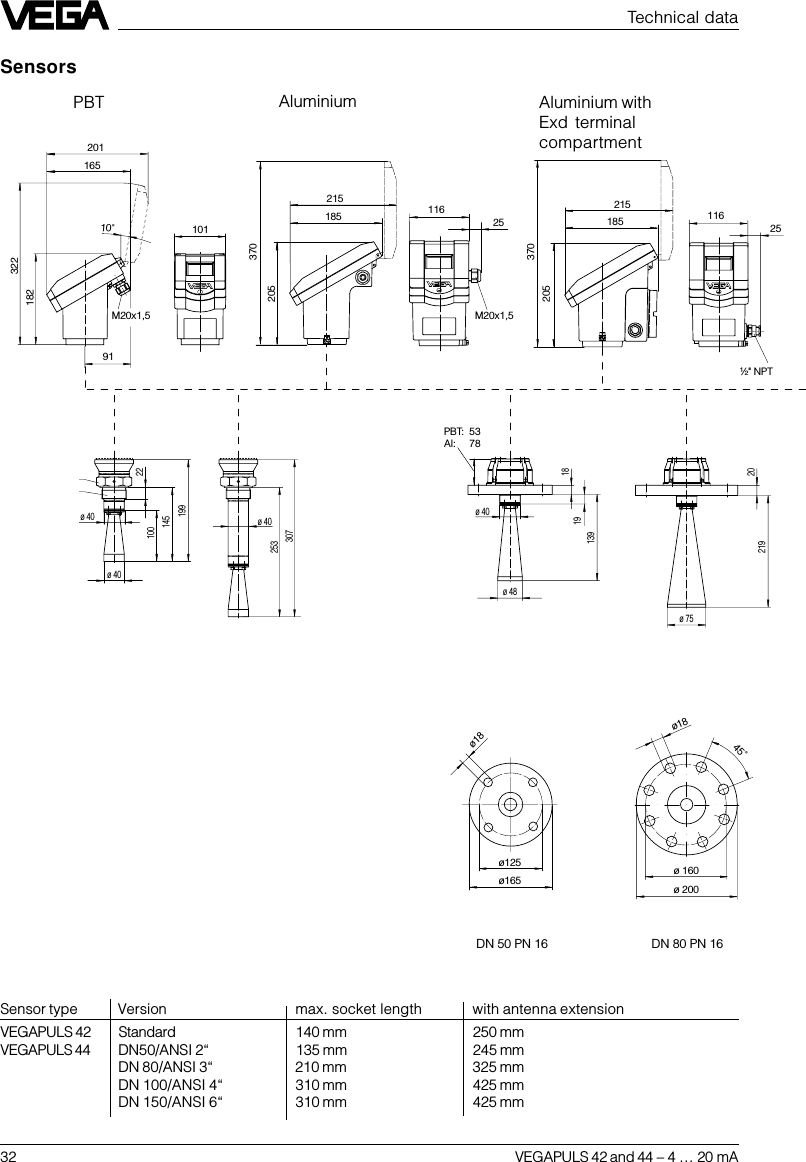
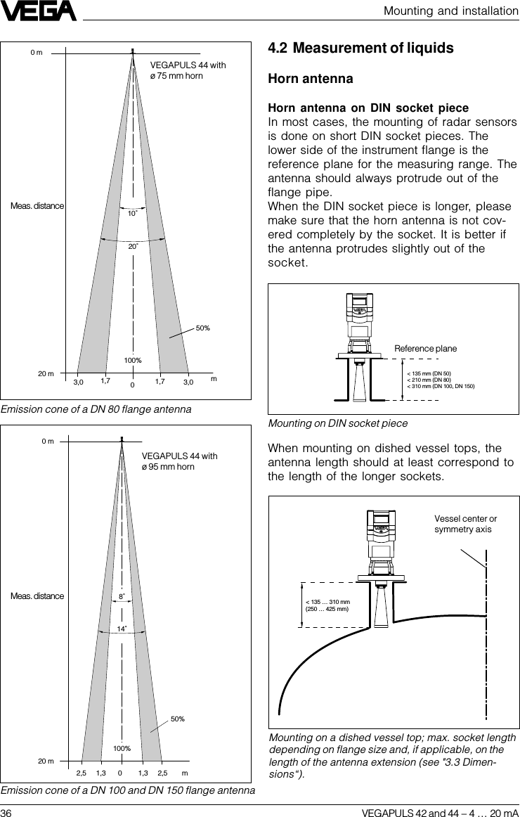
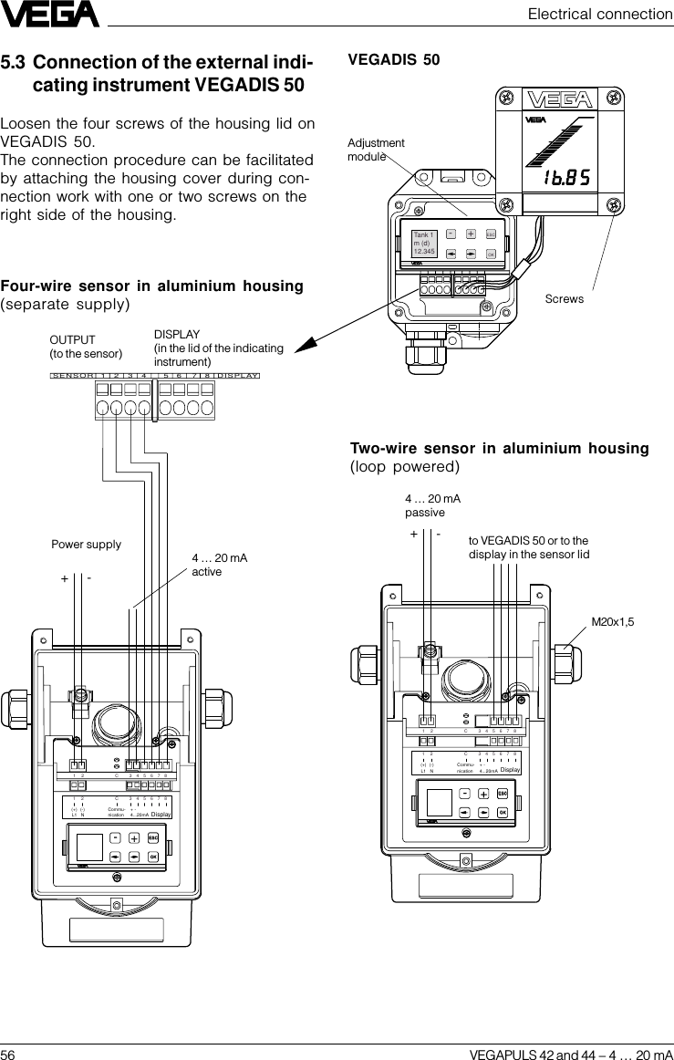
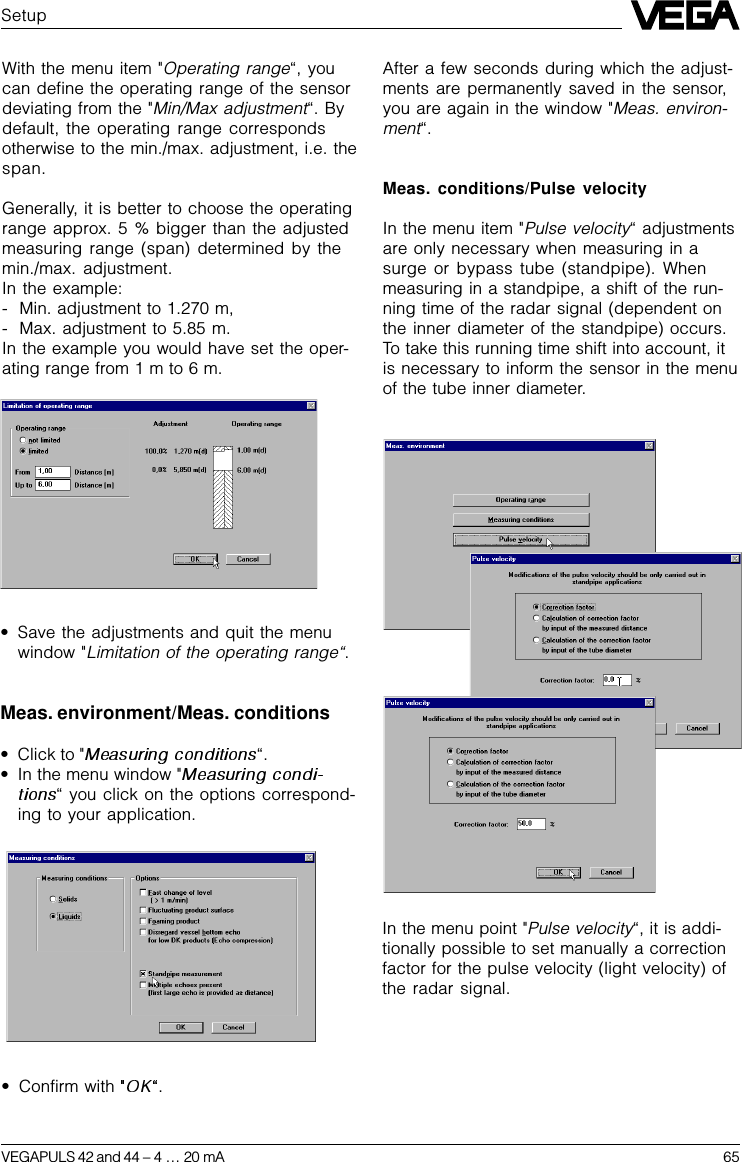
![VEGAPULS 42 and 44 –4 … 20 mA 152.1 SurveyGeneral features•Application preferably for liquids in storage tanks, reservoirs and process vessels withincreased accuracy requirements.•Measuring range 0 … 10 m or 0 … 20 m.•Ex approved in zone 1 (IEC) or zone 1 (ATEX) classificationEEx ia [ia] IIC T6.•Integrated display of measured values.SurveyVEGAPULS …42 44Signal output–active (4 … 20 mA) ••–passive (4 … 20 mA loop powered) ••Voltage supply–two-wire technology (voltagesupply and signal outputvia one two-wire cable) ••–four-wire technology (voltagesupply separate from the signalcable) ••Process fitting–G 11/2 A; 11/2“ NPT •––DN 50; ANSI 2“–•–DN 80; ANSI 3“–•–DN 100; ANSI 4“–•–DN 150; ANSI 6“–•Adjustment–PC ••–adjustment module in the sensor ••–adjustment module in externalindicating instrument ••–HART® handheld ••Measuring range max.–ø 40 mm horn 10 m ––ø 48 mm horn 15 m 15 m–ø 75 mm horn 20 m 20 m–ø 95 mm horn 20 m 20 mTypes and versions](https://usermanual.wiki/VEGA-Americas/PULS40/User-Guide-119711-Page-15.png)

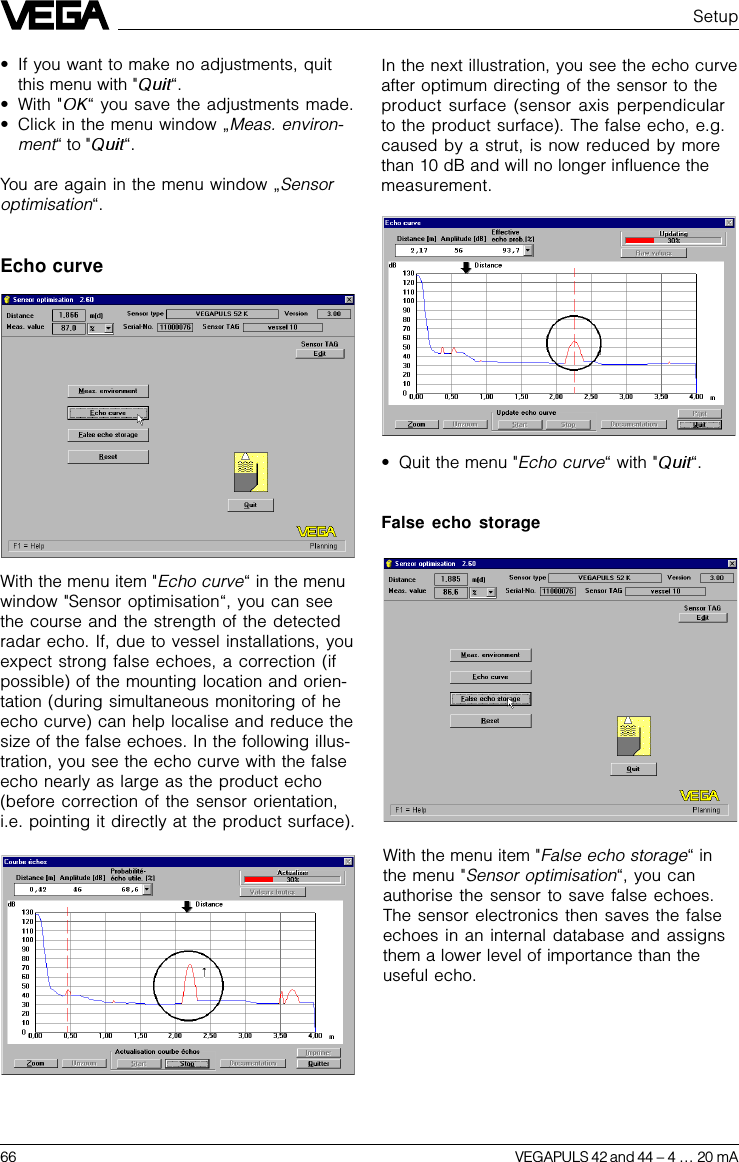
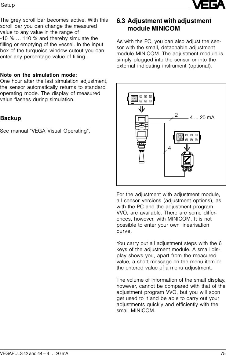
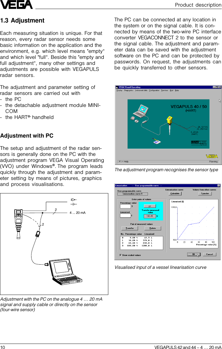
![VEGAPULS 42 and 44 –4 … 20 mA 69Max.Min.100 % (1.270 m) correspondto 1200 litersSpan (4.58 m)0 % (5.850 m) correspond to45 litersIndex marker 1 is at 0 % filling (percentagevalue [%]), corresponding in the example toan actual distance to the product surface of5.850 m (empty vessel). The volume value is45 liters (fluid remaining in the vessel). Indexmarker 2 is at a filling level of 30 % (30 % ofthe meas. distance of 1.270 m … 5.850 m). Ata filling level of 30 %, there are 576 liters inthe vessel (in our example).Index marker 3 is at a filling level of 60 %. Atthis filling level there are 646 liters in the ves-sel.Index marker 4 is at a filling level of 100 %(product distance 1.270 m), where 1200 litersare in the vessel.SetupMax. 32 index markers can be entered perlinearisation curve (value pairs).Calculating the linearisation curve(use previous tank example)In the menu window "Linearisation -- userprogrammable curve --“ you can start thevessel calculation program. With the vesselcalculation program you can calculate (usingdimensions from the technical drawings ofthe vessel) the correlation of filling height tofilling volume. If the curve is defined this way,gauging by incremental filling is not neces-sary - your sensor can then output volume asa function of level.•Click to " “.The tank calculation program starts. In thetop left corner you choose the vessel type(upright tank, cylindrical tank, spherical tank,individual tank form or matrix). When choos-ing matrix, you can enter a user programma-ble linearisation curve by means of indexmarkers. This corresponds to the entering ofvalue pairs (linearisation points), as previ-ously described.In the following example, the tank calculationprogram calculates the linearisation curve ofa vessel corresponding to the vessel in theprevious gauging example.](https://usermanual.wiki/VEGA-Americas/PULS40/User-Guide-119711-Page-69.png)