VEGA Americas PULS40 Fluid Level Radar Transmitter User Manual BA PULS5K D 1099
VEGA Americas Inc. Fluid Level Radar Transmitter BA PULS5K D 1099
manual
Level and Pressure
Operating Instructions
VEGAPULS 42 and 44
4 … 20 mA; HART® compact sensor

2VEGAPULS 42 and 44 – 4 … 20 mA
Contents
Contents
Safety information ........................................................................ 3
Note Ex area ................................................................................ 3
Quick start
Quick start with the PC ................................................................ 4
Quick start with adjustment module MINICOM ......................... 5
1 Product description
1.1 Function ................................................................................. 7
1.2 Application features ............................................................. 9
1.3 Adjustment .......................................................................... 10
1.4 Antennas ............................................................................. 12
2 Types and versions
2.1 Survey................................................................................. 15
2.2 Configuration of measuring systems ............................... 17
3 Technical data
3.1 Technical data ..................................................................... 25
3.2 Approvals ........................................................................... 30
3.3 Dimensions ......................................................................... 31
4 Mounting and installation
4.1 General installation instructions ........................................ 34
4.2 Measurement of liquids ..................................................... 36
4.3 Measurement in standpipe (surge or bypass tube) ...... 38
4.4 False echoes ...................................................................... 48
4.5 Common installation mistakes ........................................... 50

VEGAPULS 42 and 44 – 4 … 20 mA 3
Safety information
Please read this manual carefully, and also take
note of country-specific installation standards
(e.g. the VDE regulations in Germany) as well
as all prevailing safety regulations and acci-
dent prevention rules.
For safety and warranty reasons, any internal
work on the instruments, apart from that in-
volved in normal installation and electrical con-
nection, must be carried out only by qualified
VEGA personnel.
Note Ex area
Please note the approval documents (yellow
binder), and especially the included safety
data sheet.
Contents
5 Electrical connection
5.1 Connection and connection cable .................................... 53
5.2 Connection of the sensor .................................................. 54
5.3 Connection of the external indicating instrument
VEGADIS 50 ....................................................................... 56
6 Setup
6.1 Adjustment methods .......................................................... 57
6.2 Adjustment with PC ............................................................ 57
6.3 Adjustment with adjustment module MINICOM ............... 75
6.4 Adjustment with HART® handheld ..................................... 82
7.2 Error codes ........................................................................ 87
7 Diagnostics
7.1 Simulation ............................................................................ 87
4VEGAPULS 42 and 44 – 4 … 20 mA
Quick start
Quick start
In the majority of applications, the radar sen-
sor displays the distance to the product
surface immediately after the power supply is
switched on. You only have to carry out the
empty and full adjustment so that at your
required empty and full distances, 4 mA and
20 mA, respectively, are outputted.
However, it is always useful, especially under
difficult measurement conditions (process
tanks, stirrers, filling stream, vessel installa-
tions), to carry out a sensor optimisation, see
chapter "6 Setup“.
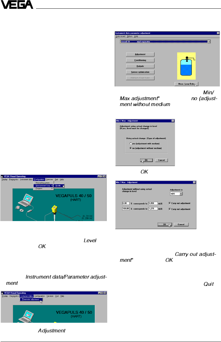
Quick start with the PC
Configuration
Start the adjustment software VVO ³2.60 with
the user level "
Planning
“.
•Click to …
… and enter a name for the measurement
loop.
•Choose under "
Application
“ e.g. " “.
•Confirm with " “.
Adjustment
•Click to "
“.
•Click in the window "
Adjustment
“ to "
and choose "
)
“ in the following
window „
Min/Max adjustment
“.
•Click to „ “.
•Enter the distance of the sensor to the
product surface at 0 % (empty) and at
100 % (full) in meters.
•Activate the two boxes "
and click to „ “.
You are again in the window "
Adjustment
“.
•Click in the window "
Adjustment
“ to " “.
The sensor will now output at the adjusted
empty distance 4 mA and at the full distance
20 mA. In the example, the sensor calibrates
the span of 5.85 m to 1.27 m
to the signal range of 4 … 20 mA.
•Then click to " “.
VEGAPULS 42 and 44 –4 … 20 mA 5
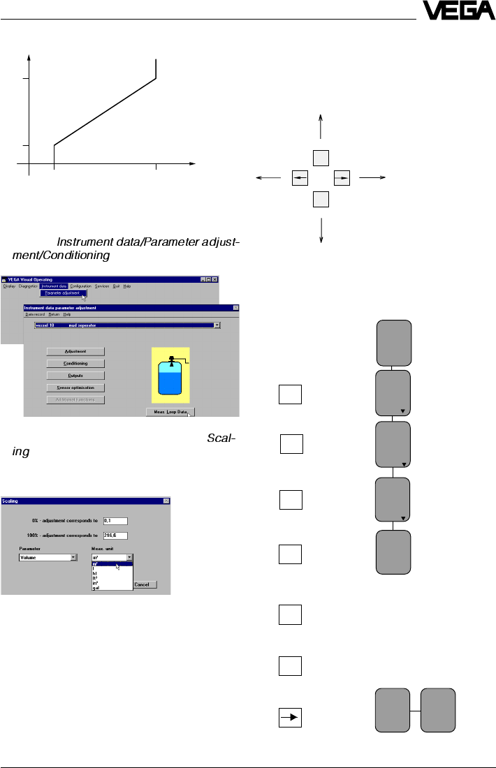
Quick start
Scaling of the measured value display
•Click to "
“.
•Click in the window "Conditioning“ to "
“.
The window …
opens.
Allocate in the menu window "
Scaling
“ a
physical quantity and the unit of measure-
ment to the 0 % and 100 % values. Here you
inform the sensor, e.g. that at 0 % filling there
are still 0.1 m3 and at 100 % filling 216.6 m3 in
the vessel. The sensor display then indicates
0.1 m3 (0 %) for an empty vessel and
216.6 m3 (100 %) for a full vessel.
Empty adjustment
Key Display text
Adjust-
ment
Para-
meter
Sensor
m(d)
4.700
w.out
medium
Adjust-
ment
in
m(d)
(Min. adjustment)
OK
OK
+
OK
OK
OK
The display text flashes and
you can choose between
"feet“ and "m“.
Confirm the adjustment with
"OK“.
ESC
OK
Quick start with adjustment module
MINICOM
In the menu field you can move with these keys to the left, right,
top and bottom.
5,85
1,27
420
m
mA
Adjust-
ment
in
m(d)
0.0%
at
m (d)
XX.XXX
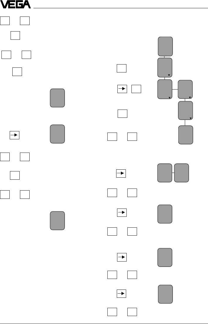
6VEGAPULS 42 and 44 –4 … 20 mA
Quick start
100.0%
at
m (d)
XX.XXX
OK
+–
or
+–
or
Enter 100 %.
The 100 % value is allocated
to the following distance and
the distance indication flashes.
Enter the distance with full
vessel, e.g. 1.27 m.
Condit-
ioning
Scal-
ing
0 %
corres
ponds
XXXX
Adjust-
ment
Para-
meter
Sensor
m(d)
4.700
(Max. adjustment)
OK
OK
Enter the figure for the filling at 0 %, e.g.
0001.
OK
+–
or
0 %
corres
ponds
XXXX
100 %
corres
ponds
XXXX
Deci-
mal
point
888.8
prop.
to
Volume
Unit
m3
+–
or Enter the figure of the 100 %
filling, e.g. 2166 for 216.6 m3
Enter the position of the
comma, so that 216.6 is dis-
played.
+–
or
Choose the physical unit, e.g.
volume.
+–
or
Choose the unit of measure-
ment, e.g. m3.
+–
or
OK
+–
or
OK
+–
or
Enter 0 %.
The 0 % value is allocated to
the following distance and the
distance indication flashes.
Enter the empty distance, e.g.
5.85 m.
The value pair 0 % and 5.85 m
is written into the sensor.
0.0%
at
m (d)
5,85
Full adjustment
Scaling of measured value display
Key Display text
100.0%
at
m (d)
1,27
VEGAPULS 42 and 44 –4 … 20 mA 7
Product description
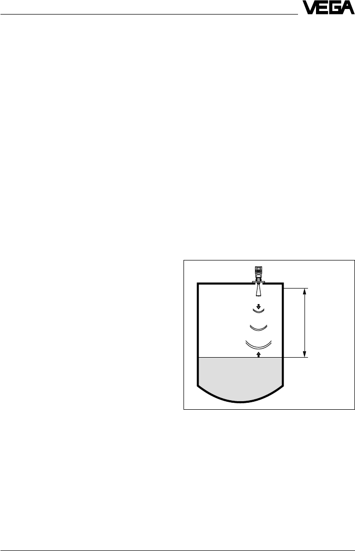
emission - reflection - reception
Meas.
distance
1 Product description
VEGAPULS series 40 sensors are a newly
developed generation of extremely compact
radar sensors for high resolution and accu-
racy. They are characterised by very good
focussing features for applications in narrow
spaces. With very modest space require-
ments, they were developed for measuring
distances of 0 … 10 m/20 m and are the right
choice for standard applications such as
storage vessels, reservoirs and buffer tanks
as well as process tanks.
Due to small housing dimensions and proc-
ess fittings, the compact sensors are an
obstrusive, and most of all, very reasonable
solution for your level measurement applica-
tions. With the integrated display they enable
high precision level measurements and can
be used for applications in which the advan-
tages of non-contact measurement could
never before be realized.
VEGAPULS 40 radar sensors are perfectly
suited to two-wire technology. The supply
voltage and the output signal are transmitted
via one two-wire cable. As output or measur-
ing signal, the instruments produce an ana-
logue 4 … 20 mA output signal.
1.1 Function
Radio detecting and ranging: Radar.
VEGAPULS radar sensors are used for non-
contact, continuous distance measurement.
The measured distance corresponds to a
filling height and is outputted as level.
Measuring principle:
emission – reflection – reception
Tiny 24 GHz radar signals are emitted from
the antenna of the radar sensor as short
pulses. The radar impulses reflected by the
sensor environment and the product are
received by the antenna as radar echoes.
The running period of the radar impulses
from emission to reception is proportional to
the distance and hence to the level.
8VEGAPULS 42 and 44 –4 … 20 mA
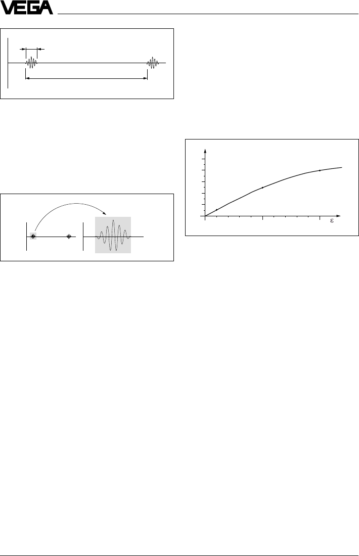
Reflected radar power dependent on the dielectric
constant of the measured product
2
0
0
10
25 %
40 %
5
10
5 %
20
30
40
50
%
4 6 8 12 14 16 18
20
r
tt
1 ns
278 ns
Time transformation
Pulse sequence
Product description
The radar impulses are emitted by the an-
tenna system as pulse packages with a
pulse duration of 1 ns and pulse intervals of
278 ns; this corresponds to a pulse package
frequency of 3.6 MHz. In the impulse inter-
vals, the antenna system operates as re-
ceiver. Signal running periods of less than
one billionth of a second must be processed
and the echo image must be evaluated in a
fraction of a second.
All products which are electrically conductive
reflect radar signals very well. Even slightly
conductive products ensure a sufficient re-
flection for a reliable measurement.
All products with a dielectric constant er of
more than 2.0 reflect radar impulses suffi-
ciently (note: air has a dielectric constant er of
1).
The signal reflection increases with the con-
ductivity or with the dielectric constant of the
product. Hence, virtually all products can be
measured.
With standard flanges of DN 50 to DN 250,
ANSI 2“ to ANSI 10“ or G 11/2 A and 11/2“ NPT,
the sensor antenna systems can be adapted
to the various measured products and meas-
urement environments.
The high-quality materials can also withstand
extreme chemical and physical conditions.
The sensors deliver a stable, reproducible
analogue or digital level signal with reliability
and precision, and have a long useful life.
VEGAPULS radar sensors can accomplish
this through a special time transformation
procedure which spreads out the more than
3.6 million echo images per second in a slow-
motion picture, then freezes and processes
them.
Hence, it is possible for the VEGAPULS 40
radar sensors to process the slow-motion
pictures of the sensor environment precisely
and in detail in cycles of 0.5 to 1 second
without using time-consuming frequency
analysis (e.g. FMCW, required by other radar
techniques).
Virtually all products can be measured
Radar signals display physical properties
similar to those of visible light. According to
the quantum theory, they propagate through
empty space. Hence, they are not depend-
ent on a conductive medium (as e.g. sound
waves in air), and spread out like light at the
speed of light. Radar signals react to two
basic electrical properties:
- the electrical conductivity of a substance
- the dielectric constant of a substance.
VEGAPULS 42 and 44 –4 … 20 mA 9
Product description
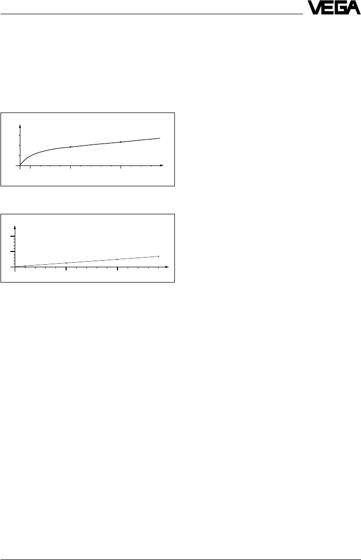
Temperature influence: Temperature error absolutely
zero (e.g. at 500°C 0.018 %)
Pressure influence: Error with pressure increase very
low (e.g. at 50 bar 1.44 %)
100 500 1000 1300 ˚C
0
0
0,01
0,02
0,03
%
0,018 % 0,023 %
10
0
0
5
%
1,44 % 2,8 %
10
50
20 30 40 60
100
70 80 90 110 120 130 140
bar
0,29 %
3,89 %
Continuous and reliable
Unaffected by temperature, pressure and
individual gas atmospheres, VEGAPULS
radar sensors are used for quick and reliable
continuous level measurement of various
products.
VEGAPULS 40 sensors enable level meas-
urement with radar in facilities where previ-
ously, due to high cost, it was completely out
of the question.
1.2 Application features
Applications
•level measurement of liquids
•measurement also in vacuum
•all slightly conductive materials and all
substances with a dielectric constant > 2.0
can be measured
•measuring range 0 … 10 m (type 42).
measuring range 0 … 20 m (type 44).
Two-wire technology
•supply and output signal on one two-wire
cable (Loop powered)
•4 … 20 mA output signal or HART® output
signal.
Rugged and abrasion proof
•non-contact
•high-resistance materials
Exact and reliable
•accuracy 0.05 %.
•resolution 1 mm.
•unaffected by noise, vapours, dusts, gas
compositions and inert gas stratification
•unaffected by varying density and tem-
perature of the medium
•measurement in pressures up to 40 bar
and product temperatures up to 200°C
Communicative
•integrated display of measured value
•optional display module separate from
sensor
•adjustment with detachable adjustment
module, pluggable in the sensor or in the
external display
•adjustment from the PLC level with the PC
•adjustment with HART® handheld
Approvals
•CENELEC, ATEX, PTB, FM, CSA, ABS,
LRS, GL, LR, FCC.
10 VEGAPULS 42 and 44 –4 … 20 mA
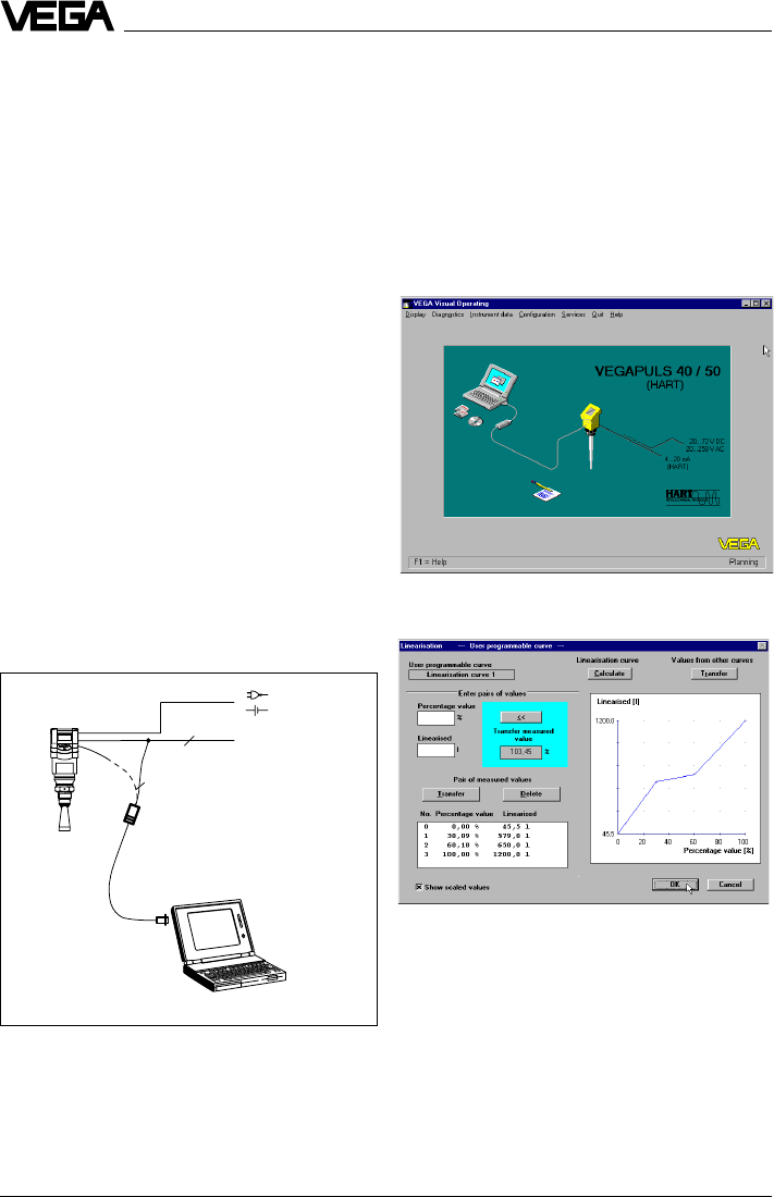
Visualised input of a vessel linearisation curve
The adjustment program recognises the sensor type
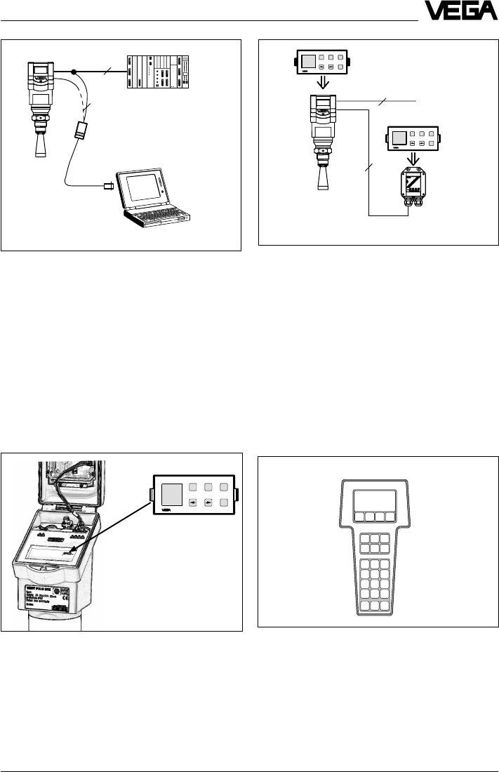
The PC can be connected at any location in
the system or on the signal cable. It is con-
nected by means of the two-wire PC interface
converter VEGACONNECT 2 to the sensor or
the signal cable. The adjustment and param-
eter data can be saved with the adjustment
software on the PC and can be protected by
passwords. On request, the adjustments can
be quickly transferred to other sensors.
Product description
1.3 Adjustment
Each measuring situation is unique. For that
reason, every radar sensor needs some
basic information on the application and the
environment, e.g. which level means "empty“
and which level "full“. Beside this "empty and
full adjustment“, many other settings and
adjustments are possible with VEGAPULS
radar sensors.
The adjustment and parameter setting of
radar sensors are carried out with
- the PC
- the detachable adjustment module MINI-
COM
- the HART®- handheld
Adjustment with PC
The setup and adjustment of the radar sen-
sors is generally done on the PC with the
adjustment program VEGA Visual Operating
(VVO) under Windows®. The program leads
quickly through the adjustment and param-
eter setting by means of pictures, graphics
and process visualisations.
Adjustment with the PC on the analogue 4 … 20 mA
signal and supply cable or directly on the sensor
(four-wire sensor)
2
2 4 ... 20 mA
VEGAPULS 42 and 44 –4 … 20 mA 11
Detachable adjustment module MINICOM
-+ESC
OK
Tank 1
m (d)
12.345
2
2
Adjustment with the PC on the 4 … 20 mA signal and
supply cable or directly on the sensor (figure: a two-
wire sensor)
Product description
Adjustment with adjustment module
MINICOM
With the small (3.2 cm x 6.7 cm) 6-key ad-
justment module with display, the adjustment
can be carried out in clear text dialogue. The
adjustment module can be plugged into the
radar sensor or into the optional, external
indicating instrument.
PLC
Unauthorised sensor adjustments can be
prevented by removing the adjustment mod-
ule.
2
4
4 ... 20 mA
-+
ESC
OK
Tank 1
m (d)
12.345
-+
ESC
OK
Tank 1
m (d)
12.345
Adjustment with detachable adjustment module. The
adjustment module can be plugged into the radar
sensor or the external indicating instrument VEGADIS
50.
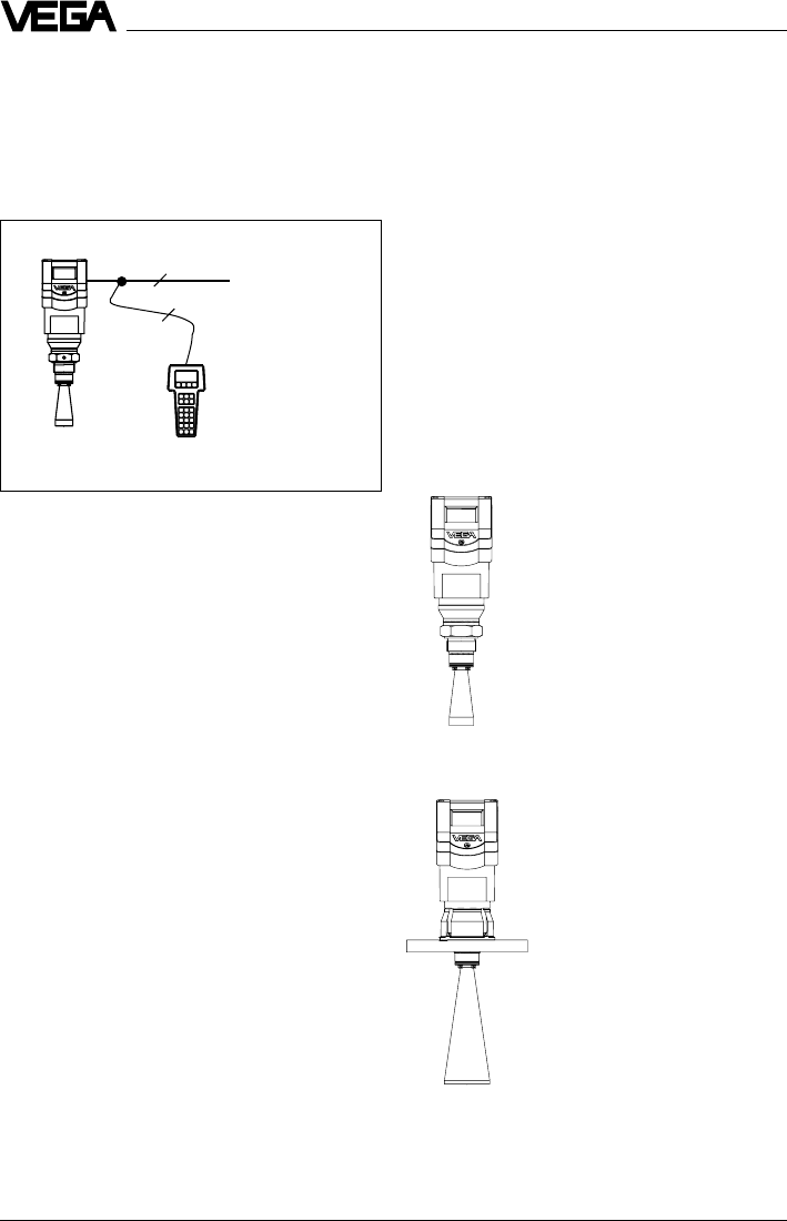
Adjustment with HART® handheld
Series 40 with 4 … 20 mA output signal can
also be adjusted with the HART® handheld.
A special DDD (Data Device Description) is
not necessary, so that the sensors can be
adjusted with the HART® standard menus of
the handheld.
HART® handheld
HART Communicator
12 VEGAPULS 42 and 44 –4 … 20 mA
1.4 Antennas
The antenna is the eye of the radar sensor.
An uninitiated observer would probably not
realise how carefully the antenna geometry
must be adapted to the physical properties
of electromagnetic fields.
The geometrical form determines focal prop-
erties and sensitivity - the same way it deter-
mines the sensitivity of a unidirectional
microphone.
Four antenna systems are available for differ-
ent applications and process requirements.
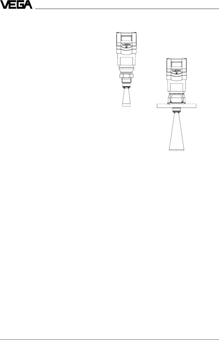
Horn antennas
Horn antennas focus the
radar signals very well.
Manufactured of 1.4435
(stainless steel) or Hastel-
loy C22, they are very rug-
ged, and are physically as
well as chemically, resistant.
They are suitable for pres-
sures up to 40 bar and for
product temperatures up to
150°C. The horn diameters
determine the focussing of
the radar signals. The an-
tenna gain grows stronger
with increasing diameter
(40, 48, 75, 95 mm). The
antenna gain represents
the ratio of emitted energy
to received echo energy.
Product description
2
2
4 ...20 mA
HART® handheld on the 4 … 20 mA signal cable
For adjustment, just connect the HART® hand-
held to the 4 … 20 mA output signal cable or
insert the two communication cables of the
HART® handheld into the adjustment jacks on
the sensor.
VEGAPULS 42
VEGAPULS 44
VEGAPULS 42 and 44 –4 … 20 mA 13
Product description
Pipe antennas
The pipe antennas on surge
or bypass tubes only form a
complete antenna system in
conjunction with a measuring
tube (which can also be
curved). The measuring tube
acts as a conductor for
radar signals. The running
period of the radar signals
changes in the tube and is
dependent on tube diameter.
The tube inner diameter must
be programmed in the sen-
sor so that it can take the
altered running time into
account and deliver precise
level signals. Pipe antennas
are especially suitable for
processes with intense
product movements or prod-
ucts with low dielectric con-
stant.
The antennas are character-
ised by very high gain. High
reliability can be achieved
even with products with very
poor reflective features.
VEGAPULS 44 on bypass tube
VEGAPULS 42 on bypass tube
14 VEGAPULS 42 and 44 –4 … 20 mA
Types and versions
2 Types and versions
Series 40 sensors are manufactured in two
basic versions, VEGAPULS 42 and VEGA-
PULS 44.
VEGAPULS 42 are characterised by a
G 11/2 A or 11/2“ NPT thread as process fitting.
These sensors are equipped as standard
versions with a ø 40 mm horn as antenna.
VEGAPULS 44 are characterised by a DIN or
ANSI flanges as process fitting. In standard
version they are manufactured with DN 50,
80, 100 and 150 as well as with ANSI 2“, 3“,
4“ and 6“. The bigger flanges come
equipped with respectively larger antenna
horns (ø 48, 75 and 95 mm).
Generally: The bigger the antenna horn, the
better the focussing characteristics, and the
better the antenna gain. This ensures that
even a weak product echo can be detected
reliably as level echo.
VEGAPULS 42
VEGAPULS 44

VEGAPULS 42 and 44 –4 … 20 mA 15
2.1 Survey
General features
•Application preferably for liquids in storage tanks, reservoirs and process vessels with
increased accuracy requirements.
•Measuring range 0 … 10 m or 0 … 20 m.
•Ex approved in zone 1 (IEC) or zone 1 (ATEX) classification
EEx ia [ia] IIC T6.
•Integrated display of measured values.
Survey
VEGAPULS …
42 44
Signal output
–active (4 … 20 mA) ••
–passive (4 … 20 mA loop powered) ••
Voltage supply
–two-wire technology (voltage
supply and signal output
via one two-wire cable) ••
–four-wire technology (voltage
supply separate from the signal
cable) ••
Process fitting
–G 11/2 A; 11/2“ NPT •–
–DN 50; ANSI 2“–•
–DN 80; ANSI 3“–•
–DN 100; ANSI 4“–•
–DN 150; ANSI 6“–•
Adjustment
–PC ••
–adjustment module in the sensor ••
–adjustment module in external
indicating instrument ••
–HART® handheld ••
Measuring range max.
–ø 40 mm horn 10 m –
–ø 48 mm horn 15 m 15 m
–ø 75 mm horn 20 m 20 m
–ø 95 mm horn 20 m 20 m
Types and versions
16 VEGAPULS 42 and 44 –4 … 20 mA
Type code
PS 42 .XX X X X XXX X X
K - Plastic housing PBT, M20 x 1,5 cable entry
N - Plastic housing PBT, 1/2“ NPT cable entry
A - Aluminium housing, M20 x 1,5 cable entry
D - Aluminium housing, 1/2“ NPT cable entry in Exd connection
housing
V - Seal of the antenna system: Viton
A - Seal of the antenna system: Kalrez
G - Process fitting G 11/2 A
N - Process fitting 11/2“ NPT
ABC- Process fitting DN 50 PN 16
BBE- Process fitting DN 80 PN 16
CBG- Process fitting DN 100 PN 16
DBG- Process fitting DN 150 PN 16
ARC- Process fitting ANSI 2“ 150 psi
BRE- Process fitting ANSI 3“ 150 psi
CRG- Process fitting ANSI 4“ 150 psi
DRG- Process fitting ANSI 6“ 150 psi
YYY- Process fitting on request
X - without display
A - with integrated display
X - without adjustment module MINICOM
B - with adjustment module MINICOM (mounted)
B - 20 … 72 V DC; 20 … 250 V AC; 4 … 20 mA, HART®
(four-wire)
D - Two-wire (loop powered), 4 … 20 mA, HART®
E - Supply via signal conditioning instrument
G - Segment coupler for Profibus PA
XX - FTZ (standard telecommunication approval Germany)
AX - Approval in Ex-Zone 1, EEx ia IIC T6
CX - Approval in Ex-Zone 0, EEx ia IIC T6
BX - Approval in Ex-Zone 1 (Exd connection housing)
DX - Approval in Ex-Zone 0 (Exd connection housing)
Type 42: with screw-on process fitting
Type 44: instrument series with flange process fitting
PS: Series 40 radar sensors
Types and versions
VEGAPULS 42 and 44 –4 … 20 mA 17
2 4 … 20 mA -
+
1)
4
2.2 Configuration of measuring
systems
A measuring system consists of a sensor
with a 4 … 20 mA signal output and a module
that evaluates and further processes the
level-proportional current signal.
On the following pages you will see various
measuring systems, each consisting of a
different instrument configuration (several
also with signal conditioning).
Measuring systems in two-wire technol-
ogy:
•4 … 20 mA shown without processing unit,
(bottom)
•4 … 20 mA on active PLC,
(page 18)
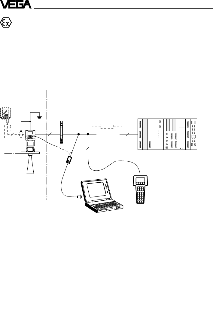
•4 … 20 mA in Ex area on active PLC
(Ex ia
page 20, Ex d PAGE 23)
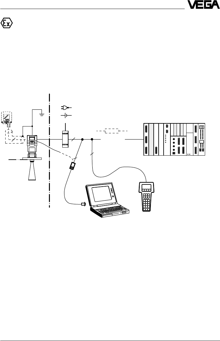
•4 … 20 mA in Ex area on passive PLC,
(page 21)
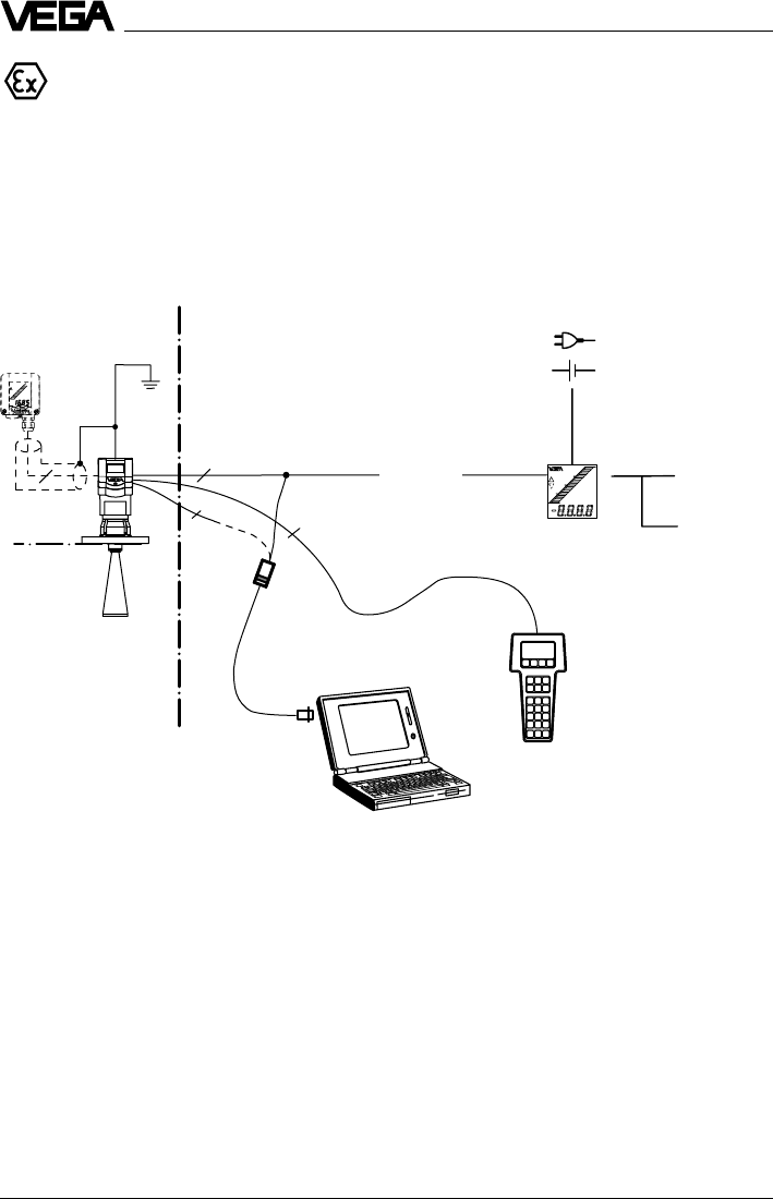
•4 … 20 mA in Ex area on VEGADIS 371 Ex
indicating instrument,
(page 22)
Measuring systems in four-wire technol-
ogy:
•4 … 20 mA shown without signal condi-
tioning instrument,
(non Ex page 19, Ex d
page 23)
VEGADIS 50
VEGA-
CONNECT 2
HART® handheld
Types and versions
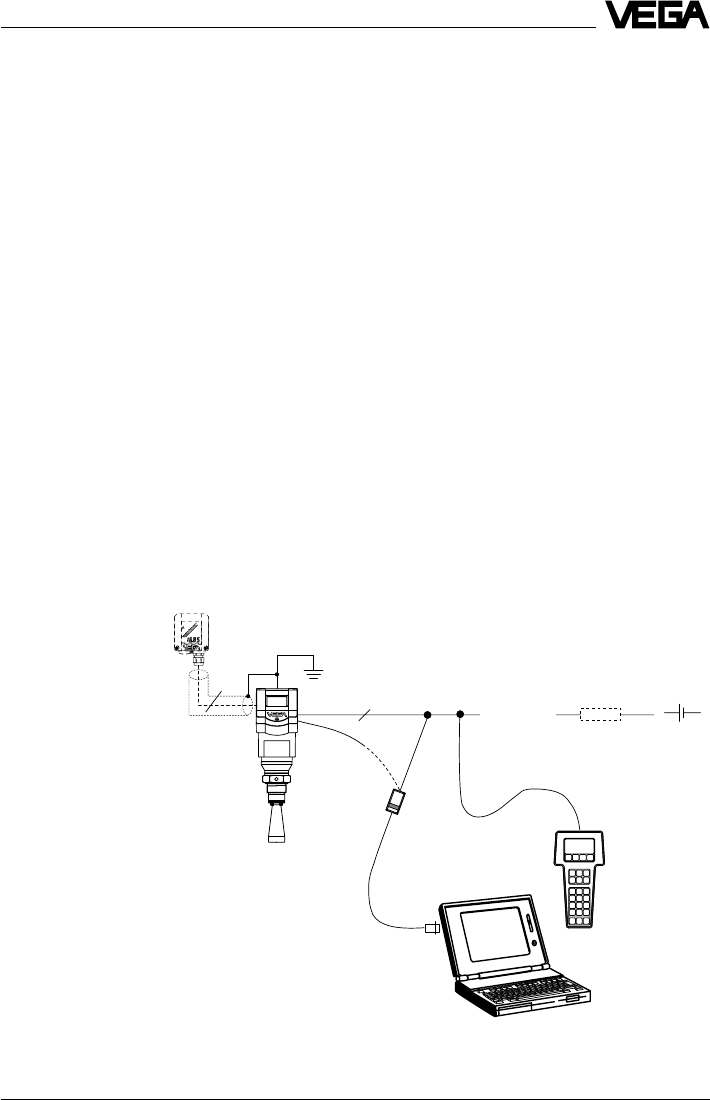
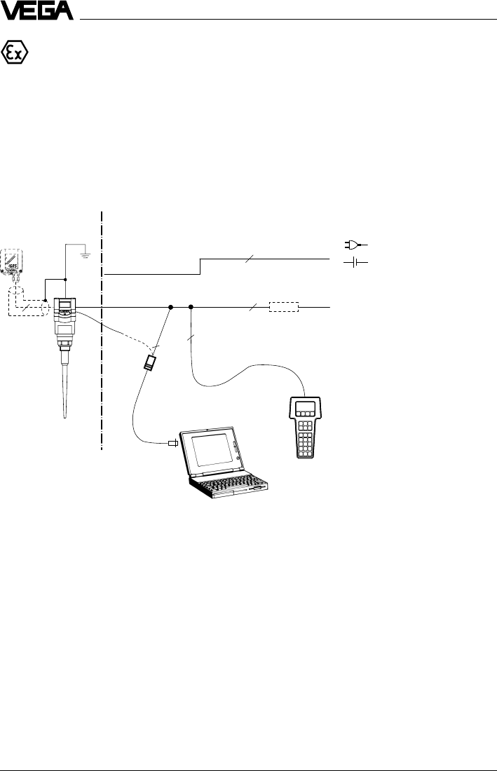
Measuring systems with VEGAPULS 42 or 44 connected to any 4 … 20 mA signal
processing unit
•Two-wire technology (loop powered), supply and output signal via one two-wire cable.
•Output signal 4 … 20 mA (passive).
•Optional external indicating instrument with analogue and digital display (can be mounted
up to 25 m separated from the sensor).
•Adjustment with PC, HART® handheld or the adjustment module MINICOM (can be plugged
into the sensor or into the external indicating instrument VEGADIS 50).
1) If the resistance of the processing systems
connected to the 4 … 20 mA signal output is less
than 250 W, a resistor must be connected to the
connection cable during adjustment to get a loop
resistance of 250 W.
The digital adjustment signal would otherwise be
severely damped or short-circuited due to
insufficient resistance of the connected
processing system. Communication with the PC
would not be ensured.
18 VEGAPULS 42 and 44 –4 … 20 mA
2 2
4 … 20 mA
4
22
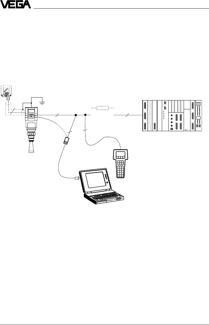
Measuring system with VEGAPULS 42 or 44 on active PLC
•Two-wire technology, supply by active PLC.
•Output signal 4 … 20 mA (passive).
•Measured value display integrated in the sensor.
•Optional external indicating instrument (can be mounted up to 25 m separated from the
sensor in Ex area).
•Adjustment with PC, HART® handheld or the adjustment module MINICOM (can be plugged
into the sensor or into the external indication instrument).
HART® handheld
VEGA-
CONNECT 2
Types and versions
1) If the resistance of the processing systems
connected to the 4 … 20 mA signal output is less
than 250 W, a resistor must be connected to the
connection cable during adjustment to get a loop
resistance of 250 W.
The digital adjustment signal would otherwise be
severely damped or short-circuited due to
insufficient resistance of the connected processing
system. Communication with the PC would not be
ensured.
1)
VEGADIS 50
passive 2)
PLC (active) 3)
2) 4 … 20 mA passive means that the sensor
consumes a level-dependent current of
4 … 20 mA. The sensor reacts electrically like a
varying resistor (consumer) to the PLC.
3) Active means that the PLC powers the passive
sensor as voltage source.
VEGAPULS 42 and 44 –4 … 20 mA 19
Types and versions
2
-
+
4 … 20mA
2
2
2
1)
4
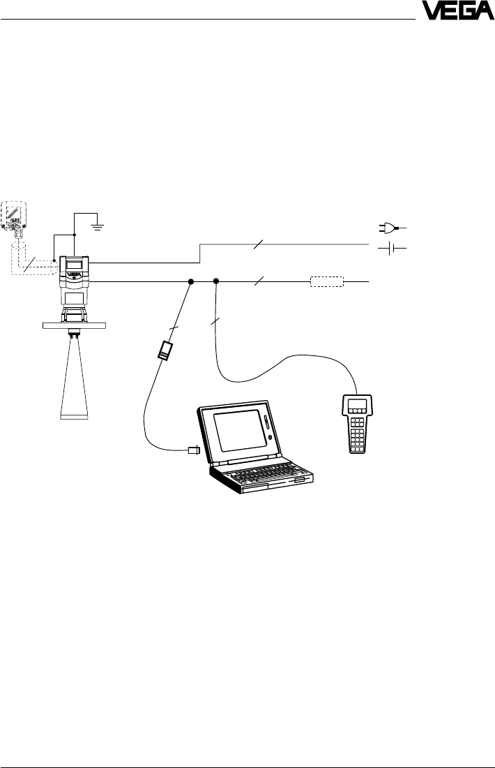
Measuring system with VEGAPULS 42 or 44 in four-wire technology
•Four-wire technology, supply and output signal via two separate two-wire cables.
•Output signal 4 … 20 mA active.
•Optional external indicating instrument with analogue and digital display (can be mounted
up to 25 m separated from the sensor).
•Adjustment with PC, HART® handheld or adjustment module MINICOM (can be plugged into
the sensor or into the external indicating instrument VEGADIS 50).
•Max. resistance on the signal output (load) 500 W.
(active) 2)
VEGADIS 50
1) If the resistance of the processing systems
connected to the 4 … 20 mA signal output is less
than 250 W, a resistor must be connected to the
connection cable during adjustment to get a loop
resistance of 250 W.
The digital adjustment signal would otherwise be
severely damped or short-circuited due to
insufficient resistance of the connected
processing system. Communication with the PC
would not be ensured.
HART® handheld
VEGA-
CONNECT 2
³ 250 W
2) 4 … 20 mA active means that the sensor delivers
a level-dependent current of 4 … 20 mA (source).
The sensor reacts electrically to the processing
system (e.g. display) like a current source.
20 VEGAPULS 42 and 44 –4 … 20 mA
2 4 … 20 mA 2
2
2
4
Types and versions
Measuring system with VEGAPULS 42 or 44 via separator in Ex area on ac-
tive PLC
•Two-wire technology (loop powered), supply via the signal line of the PLC; output signal
4 … 20 mA (passive).
•Separator transfers the non intrinsically safe PLC circuit to the intrinsically safe circuit, so
that the sensor can be used in Ex zone 1 or Ex zone 0.
•Optional external indicating instrument with analogue and digital display (can be mounted
up to 25 m separated from the sensor).
•Adjustment with PC, HART® handheld or adjustment module MINICOM (can be plugged into
the sensor or into the external indicating instrument VEGADIS 50).
HART® handheld
Ex area Non Ex area
Separator (e.g. Stahl)
(see "3.2 Approvals“)
VEGA-
CONNECT 2
VEGADIS 50
passive 2)
1)
PLC (active)
1) If the resistance of the processing systems
connected to the 4 … 20 mA signal output is less
than 250 W, a resistor must be connected to the
connection cable during adjustment to get a loop
resistance of 250 W.
The digital adjustment signal would otherwise be
severely damped or short-circuited due to
insufficient resistance of the connected
processing system. Communication with the PC
would not be ensured.
Zone 0 or
Zone 1
EEx ia
2) 4 … 20 mA passive means that the sensor
consumes a level-dependent current of
4 … 20 mA. The sensor reacts electrically like a
varying resistor (consumer) to the PLC. The PLC
operates active, i.e. as current or voltage source.
VEGAPULS 42 and 44 –4 … 20 mA 21
2 4 … 20 mA
2
2
4
-
+
Measuring system with VEGAPULS 42 or 44 via separator (Smart-Transmit-
ter) on passive PLC
•Two-wire technology (loop powered), intrinsically safe ia supply via the signal cable of the
separator for operation of the sensor in Ex zone 1 or Ex zone 0.
•Output signal sensor 4 … 20 mA passive.
Output signal separator 4 … 20 mA active.
•Optional external indicating instrument with analogue and digital display (can be mounted
up to 25 m separated from the sensor).
•Adjustment with PC, HART® handheld or adjustment module MINICOM (can be plugged into
the sensor or into the external indicating instrument VEGADIS 50).
Types and versions
(active) 2)
VEGA-
CONNECT 2
Separator (e.g. VEGATRENN 149 Ex see
"3.2 Approvals“)
VEGADIS 50
1)
PLC (passive) 3)
Ex area Non Ex area
1) If the resistance of the processing systems
connected to the 4 … 20 mA signal output is less
than 250 W, a resistor must be connected to the
connection cable during adjustment to get a loop
resistance of 250 W.
The digital adjustment signal would otherwise be
severely damped or short-circuited due to
insufficient resistance of the connected
processing system. Communication with the PC
would not be ensured.
2) 4 … 20 mA active means that the separator
delivers a level-dependent current of 4 … 20 mA
(source). The separator reacts electrically to the
PLC like a current source.
3) 4 … 20 mA passive means that the PLC consumes
a level-dependent current of 4 … 20 mA. The PLC
reacts electrically like a varying resistor
(consumer) to the PLC.
HART® handheld
Zone 0 or
Zone 1
EEx ia
22 VEGAPULS 42 and 44 –4 … 20 mA
Types and versions
2
2
42
-
+
4 ... 20 mA
VEGADIS
371 Ex
Measuring system with VEGAPULS 42 or 44 on VEGADIS 371 Ex indicating
instrument with current and relay output
•Two-wire technology (loop powered), intrinsically safe ia supply via the signal cable of the
VEGADIS 371 Ex indicating instrument for operation of the sensor in Ex zone 1 or Ex
zone 0.
•Optional external indicating instrument with analogue and digital display (can be mounted
up to 25 m separated from the sensor).
•Adjustment with PC, HART® handheld or adjustment module MINICOM (can be plugged into
the sensor or into the external indicating instrument VEGADIS 50).
(passive)
VEGADIS 50
0/4 … 20 mA
(active)
Relay
(see "3.2 Approvals“)
Ex area Non Ex area
HART® handheld
VEGA-
CONNECT 2
1) If the resistance of the processing systems
connected to the 4 … 20 mA signal output is less
than 250 W, a resistor must be connected to the
connection cable during adjustment to get a loop
resistance of 250 W.
The digital adjustment signal would otherwise be
severely damped or short-circuited due to
insufficient resistance of the connected
processing system. Communication with the PC
would not be ensured.
1)
Zone 0 or
Zone 1
EEx ia
VEGAPULS 42 and 44 –4 … 20 mA 23
Types and versions
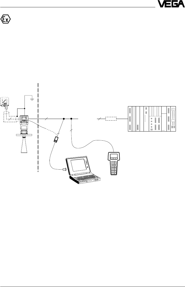
VEGAPULS 42 Ex or 44 Ex (loop powered) with pressure-tight encapsulated
terminal compartment on active PLC
•Two-wire technology, supply via the signal cable of active PLC on Exd connection housing
for operation in Ex zone 1 (VEGAPULS …Ex) or Ex zone 0 (VEGAPULS …Ex0).
•Output signal 4 … 20 mA (passive).
•Measured value display integrated in the sensor.
•Optional external indicating instrument (can be mounted up to 25 m separated from the
sensor in Ex area).
•Adjustment with PC, HART® handheld or adjustment module MINICOM (can be plugged into
the sensor or into the external indicating instrument VEGADIS 50).
1) If the resistance of the processing systems
connected to the 4 … 20 mA signal output is less
than 250 W, a resistor must be connected to the
connection cable during adjustment to get a loop
resistance of 250 W.
The digital adjustment signal would otherwise be
severely damped or short-circuited due to
insufficient resistance of the connected
processing system. Communication with the PC or
the HART® handheld would not be ensured.
2 4 … 20 mA
2
2
42
VEGA-
CONNECT 2
VEGADIS 50 Ex
passive 2)
Ex area Non Ex-area
HART® hand-
held
PLC (active)
2) 4 … 20 mA passive means that the sensor
consumes a level-dependent current of
4 … 20 mA. The sensor reacts electrically like a
varying resistor (consumer) to the PLC.
24 VEGAPULS 42 and 44 –4 … 20 mA
Technical data
VEGAPULS 42 Ex or 44 Ex with pressure-tight encapsulated connection
compartment in four-wire technology
•Four-wire technology, supply and output signal via two separate two-wire cables for use in
Ex zone 1 (VEGAPULS …Ex) or Ex zone 0 (VEGAPULS …Ex0).
•Output signal 4 … 20 mA (active).
•Optional external indicating instrument with analogue and digital display (can be mounted
up to 25 m separated from the sensor in Ex area).
•Adjustment with PC, HART® handheld or adjustment module MINICOM (can be plugged into
the sensor or into the external indicating instrument VEGADIS 50).
•Load max. 500 W.
2
2
42
2
-
+
4 … 20mA
> 250 Ω
1) If the resistance of the processing systems
connected to the 4 … 20 mA signal output is less
than 250 W, a resistor must be connected to the
connection cable during adjustment to get a loop
resistance of 250 W.
The digital adjustment signal would otherwise be
severely damped or short-circuited due to
insufficient resistance of the connected
processing system. Communication with the PC or
the HART® handheld would not be ensured.
VEGA-
CONNECT 2
VEGADIS 50 Ex
Ex area
active 2)
HART® handheld
Non Ex area
2) 4 … 20 mA active means that the sensor delivers
a level-dependent current of 4 … 20 mA (source).
The measuring signal of the sensor reacts
electrically to the processing system (e.g. display)
like a current source.
VEGAPULS 42 and 44 –4 … 20 mA 25
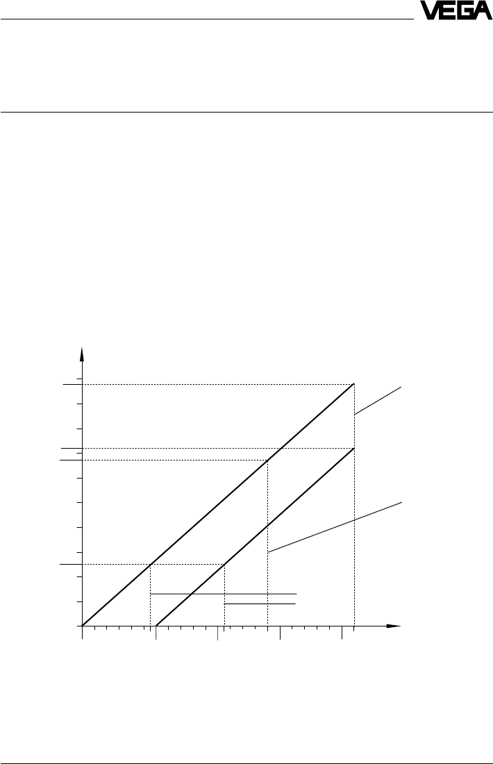
1000
900
800
700
670
600
500
400
300
250
200
100
0
14 20 25 30 35
15 29 36
V
Ω
975
720
25,5
19,5
Adjustment
resistor
(HART® and
VEGACON-
NECT)
max. voltage limit
Ex ia sensors
max. voltage limit
Non Ex and
Ex d ia sensors
min. voltage limit when using the HART®
adjustment resistor:
- Non Ex and Ex ia sensors
- Ex d ia sensors
Non Ex and Ex ia
Exd ia
3 Technical data
3.1 Technical data
Power supply
Supply voltage
- four-wire sensor 24 V DC (20 … 72 V DC)
230 V AC (20 … 250 V AC), 50/60 Hz
fuse 0.2 A TR
- two-wire sensor 24 V DC (14 … 36 V DC)
- two-wire Ex ia sensor 24 V DC (14 … 29 V DC)
- two-wire Ex d ia sensor 24 V DC (20 … 36 V DC)
Current consumption
- four-wire sensor max. 60 mA
- two-wire sensor max. 22.5 mA
Power consumption
- four-wire sensor max. 200 mW, 1.2 VA
- two-wire sensor 55 … 810 mW
Load
- four-wire sensor max. 500 Ohm
- two-wire sensor see diagram
Technical data
max. load Non Ex
max. load Ex d ia
max. load Ex ia

26 VEGAPULS 42 and 44 –4 … 20 mA
Technical data
Measuring range 1)
VEGAPULS 42 (ø 40 mm horn)
- optional 0 … 10 m
ø 48 mm horn 0 … 15 m
ø 75, 95 mm horn 0 … 20 m
VEGAPULS 44
- DN 50, ANSI 2“0 … 15 m
- DN 80, 100, ANSI 3“, 4“, 6“0 … 20 m
Standpipe measurement in DN 50 standpipe
- VEGAPULS 42 0 … 20 m
- VEGAPULS 44 0 … 20 m
Standpipe measurement in DN 100 standpipe
- VEGAPULS 42 0 … 20 m
- VEGAPULS 44 0 … 20 m
Output signal
4 … 20 mA current signal in two or four-wire technology
Integration time 0 … 999 seconds (adjustable)
Load
-4 … 20 mA two-wire
Non Ex: max 975 W
Ex d ia: max. 720 W
Ex ia: max. 670 W
-4 … 20 mA four-wire 500 W
Two-wire technology 4 … 20 mA:
The analogue 4 … 20 mA output signal (measuring signal) is transmitted together with the
power supply via one two-wire cable.
Four-wire technology 4 … 20 mA:
Separate power supply. The analogue 0/4 … 20 mA output signal (measuring signal) is led
in a cable separate from the supply voltage.
Measured value display (optional)
Liquid-crystal display
- in the sensor scalable output of measured values as graph
and digital value
- powered externally from the sensor scalable output of measured values as graph
and digital value. Measured value display can
be mounted up to 25 m away from the sensor.
Adjustment
- PC and adjustment software VEGA Visual Operating
- adjustment module MINICOM
- HART® handheld
1) Min. distance of the antenna to the medium 5 cm

VEGAPULS 42 and 44 –4 … 20 mA 27
Technical data
Accuracy 2)
(typical values under reference conditions, all statements relate to the nominal measuring
range)
Characteristics linear
Deviation in characteristics including
linearity, reproducibility and
hysteresis (determined acc. to the
limit point method) < 0.05 %
Linearity better than 0.05 %
Average temperature coefficient of the
zero signal 0.06 %/10 K
Resolution in general max. 1 mm
Resolution of the output signal 0.01 % or 1 mm
Characteristics 1)
(typical values under reference conditions, all statements relate to the nominal measuring
range)
Min. span between
full and empty > 10 mm (recommended > 50 mm)
Frequency 24 GHz technology
Intervals
- two-wire sensor (4 … 20 mA) 1 s
- two-wire sensor (digital) 0.6 s
- four-wire sensor 0.5 s
Beam angle (at –3 dB)
- VEGAPULS 42 22°
optional 18°, 10° and 8° when using bigger coupling
horn deviating from nominal size
- VEGAPULS 44
DN 50, ANSI 2“18°
DN 80, ANSI 3“10°
DN 100, ANSI 4“8°
DN 150, ANSI 6“8°
Adjustment time (response time) > 1 s (depending on parameter setting)
Influence of the process temperature not measurable at 0 bar; at 5 bar 0.004 %/10 K;
at 40 bar 0.03 %/10 K
Influence of the process pressure 0.0265 %/bar
Adjustment time 2) > 1 s (depending on parameter setting)
Radar emitted power (average) 0.717 µW
Received average emitted power 3)
- distance 1 m 0.5 … 1.5 nW pro cm² (0.5 … 1.5 x 10⁻⁹W/cm²)
- distance 5 m 0.02 … 0.6 nW pro cm²
1) Similar to DIN 16 086, reference conditions acc. to IEC 770, e.g.
temperature 15°C … 35°C; moisture 45 % … 75 %; pressure 860 mbar … 1060 mbar
2) The adjustment time (also actuating time, response time or adjustment period) is the time the sensor
requires to output the correct level (with max. 10% deviation) after a quick level change.
3) Average emitted power reaching an object (electromagnetic energy) per cm² directly in front of the antenna.
The received emitted power depends on the antenna version and the distance.

28 VEGAPULS 42 and 44 –4 … 20 mA
Technical data
Ambient conditions
Vessel pressure
- VEGAPULS 42 -1 … 16 bar
- VEGAPULS 44 -1 … 40 bar
Ambient temperature on the housing -40°C … +80°C
Process temperature (flange temperature)-40°C … +150°C
Storage and transport temperature -60°C … +80°C
Protection IP 66 and IP 67
Protection class
- two-wire sensor II
- four-wire sensor I
Overvoltage category III
Ex technical data
For comprehensive data, see attached approval documents (yellow folder)
Intrinsically safe version
- classification ia intrinsically safe in conjunction with a separator
or safety barrier
- classification number II 2G EEx ia II T6
- Ex approved Zone 1 (ATEX)
Zone 1 (CENELEC, PTB, IEC)
or
- classification number II 1G EEx ia IIC T6
- Ex approved Zone 0, Zone 1 (ATEX)
Zone 0, Zone 1 (CENELEC, PTB, IEC)
Pressure-tight encapsulated version
- classification d pressure-tight encapsulated housing (Ex d)
- classification number II 2G EEx d ia IIC T6
- Ex approved Zone 1 (ATEX)
Zone 1 (CENELEC; PTB, IEC)
or
- classification number II 1/2G EEx d ia IIC T6
- Ex approved Zone 0, Zone 1 (ATEX)
Zone 1 (CENELEC; PTB, IEC)
Permissible ambient temperature on the housing
- T6 -40°C … +55°C
- T5 -40°C … +70°C
- T4, T3 -40°C … +85°C
- T2, T1 -40°C … +70°C
Permissible ambient temperature on the
antenna system when used in Ex areas
- T6 -40°C … +85°C
- T5 -40°C … +100°C
- T4 -40°C … +135°C
- T3 -40°C … +150°C

VEGAPULS 42 and 44 –4 … 20 mA 29
Process fittings
VEGAPULS 42 G 11/2 A, 11/2“ NPT screw-on antenna
with ø 40 mm antenna horn (antenna horns
of ø 48 … 95 mm can be retrofitted as option)
VEGAPULS 44 DN 50, DN 80, DN 100, DN 150, ANSI 2“, 3“, 4“
and 6“ (horn antenna)
Connection cable
Two-wire sensors supply and signal via one
two-wire cable
Four-wire sensor supply and signal separate
Cross-section area of conductor generally 2.5 mm2
Ground connection max. 4 mm2
Cable entry
- ia terminal compartment 2 x M20 x 1.5 (cable diameter 5 … 9 mm)
- Exd terminal compartment 2 x 1/2“ NPT EEx d (cable diameter
3.1 … 8.7 mm or 0.12 … 0.34 inch)
Materials
Housing PBT (Valox) or
aluminium die-casting (GD-AlSi 10 Mg)
EEx d connection compartment aluminium ingot casting (GK-AlSi 7 Mg)
Process fitting 1.4435
Antenna (wetted parts) 1.4435 and PTFE
Antenna seal with
horn and pipe antenna
- standard Viton
- option Kalrez, Viton for low temperature
Weights
VEGAPULS 42 1.5 … 3.6 kg
VEGAPULS 44
- DN 50 5.8 … 6.5 kg
- DN 80 7.6 … 8.4 kg
- DN 100 8.6 … 9.4 kg
- DN 150 13.5 … 14.2 kg
- ANSI 2“5.2 … 5.7 kg
- ANSI 3“6.9 … 7.5 kg
- ANSI 4“10.5 … 11.1 kg
- ANSI 6“14.6 … 15.4 kg
CE conformity
VEGAPULS 42/44 radar sensors meet the protective regulations of EMC (89/336/EWG)
and NSR (73/23/EWG). The conformity has been judged acc. to the following standards:
EMC Emission EN 50 081 - 1: 1992; EN 50 041: 1997
Susceptibility EN 50 082 - 2: 1995; EN 50 020: 1994
NSR EN 61 010 - 1: 1993
Technical data

30 VEGAPULS 42 and 44 –4 … 20 mA
3.2 Approvals
When using radar sensors in Ex areas or on
ships, the instruments must be suitable and
approved for the explosion zones and appli-
cations.
The suitability is checked by the approval
authorities and is certified in approval docu-
ments.
Please note the attached approval docu-
ments when using a sensor in Ex area.
Test and approval authorities
VEGAPULS radar sensors are tested and
approved by the following monitoring, test
and approval authorities:
-PTB
(Physikalisch Technische Bundesanstalt -
Physical Technical Approval Authority)
-FM
(Factory Mutual Research)
-ABS
(American Bureau of Shipping)
-LRS
(Lloyds Register of Shipping)
-GL
(German Lloyd)
-CSA
(Canadian Standards Association)
Technical data
Intrinsically safe in Ex environment
Series 40 sensors in EEx ia (intrinsically safe)
version require for use in Ex areas special
separators or safety barriers. The separators
or safety barriers provide intrinsically safe
(ia) circuits. Below, a selection of instruments
with which series 40 sensors work reliably.
Separator and signal conditioning instru-
ment:
- VEGADIS 371 Ex
- A puissance 3 PROFSI 37-24070A
- VEGAMET 614 Ex
- Apparatebau Hundsbach
AH MS 271-B41EEC 010
Separator:
- VEGATRENN 149 Ex…
- Stahl 9303/15/22/11
- CEAG GHG 124 3111 C1206
Safety barrier:
- Stahl 9001/01/280/110/10
- CEAG GHG 11 1 9140 V0728
- Typ 9130 (VEGA)
- Stahl 9001/51/280/110/14
- MTL 787 S+
- CEAG CS 3/420-106
Pressure-tight encapsulated in Ex area
Series 42/44 sensors in EEx d ia (pressure-
tight encapsulated) version can be used in
Ex areas without special safety barriers, due
to their pressure-tight encapsulated terminal
compartment (provided the appropriate
installation regulations are observed).
VEGAPULS 42 and 44 –4 … 20 mA 31
Technical data
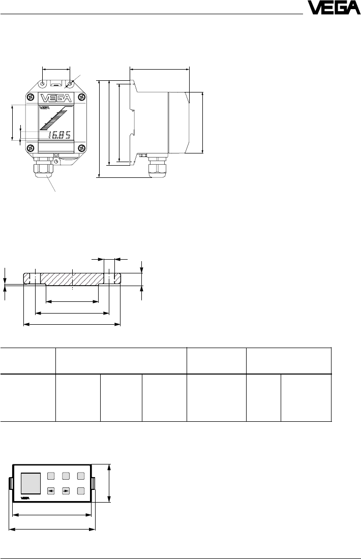
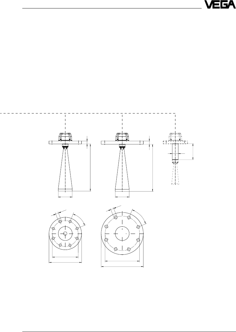
Flange dimensions acc. to ANSI
D = outer flange diameter
b = flange thickness
k = diameter of hole circle
d1= seal ledge diameter
f = seal ledge thickness
1/16" = approx. 1.6 mm
d2= diameter of holes
External indicating instrument VEGADIS 50
82
Pg 13,5
118
108
135
38
85
ø5
10
48
Mounting on carrier rail 35 x 7.5 acc. to EN 50 022 or flat
screwed
f
d
b
d
k
D
2
1
Note:
The cable diameter of the connection cable
should be at least 5 mm and max. 9 mm.
Otherwise the seal effect of the cable entry
would not be ensured.
Size Flange Seal ledge Holes
Db k d
1No. d2
2" 150 psi 152.4 20.7 120.7 91.9 4 19.1
3" 150 psi 190.5 25.5 152.4 127.0 4 19.1
4" 150 psi 228.6 25.5 190.5 157.2 8 19.1
6" 150 psi 279.4 27.0 241.3 215.9 8 22.4
3.3 Dimensions
Adjustment module MINICOM
-+ESC
OK
Tank 1
m (d)
12.345
74
32,5
67,5
Adjustment module for insertion into series 50
sensors or into the external indicating instru-
ment VEGADIS 50
32 VEGAPULS 42 and 44 –4 … 20 mA
Technical data
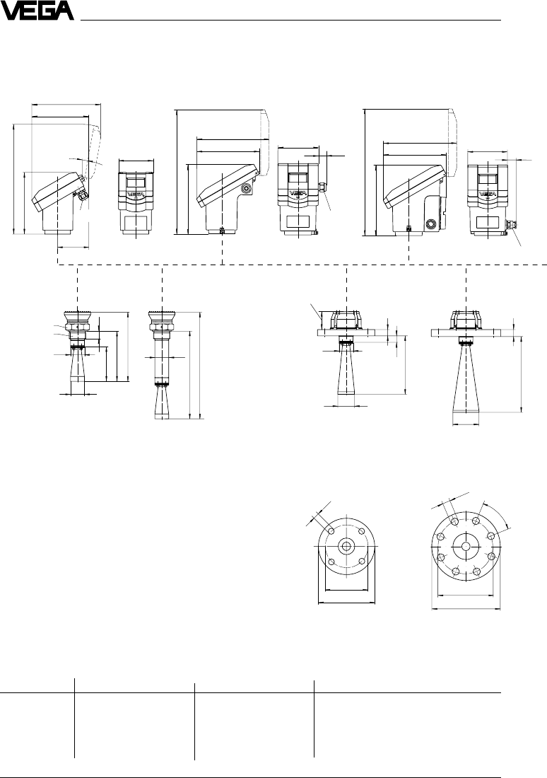
215
185
370
205
185
215
370
205
116
25 116
25
M20x1,5
½" NPT
201
10˚
101
91
182
322
M20x1,5
165
ø 40
100
22
145
199
ø 40
253
ø 40
307
ø125
ø18
ø165
19
18
139
ø 48
ø 40
PBT: 53
Al: 78
ø 160
ø18
ø 200
45˚
20
ø 75
219
DN 50 PN 16 DN 80 PN 16
Sensor type Version max. socket length with antenna extension
VEGAPULS 42 Standard 140 mm 250 mm
VEGAPULS 44 DN50/ANSI 2“ 135 mm 245 mm
DN 80/ANSI 3“ 210 mm 325 mm
DN 100/ANSI 4“ 310 mm 425 mm
DN 150/ANSI 6“ 310 mm 425 mm
PBT Aluminium Aluminium with
Exd terminal
compartment
Sensors
VEGAPULS 42 and 44 – 4 … 20 mA 33
Technical data
ø 180
ø 220
45˚
ø18
20
319
ø 95
ø 240
ø22
ø 285
45˚
ø 95
319
22
DN 100 PN 16 DN 150 PN 16
ø 40
108
34 VEGAPULS 42 and 44 –4 … 20 mA
Mounting and installation
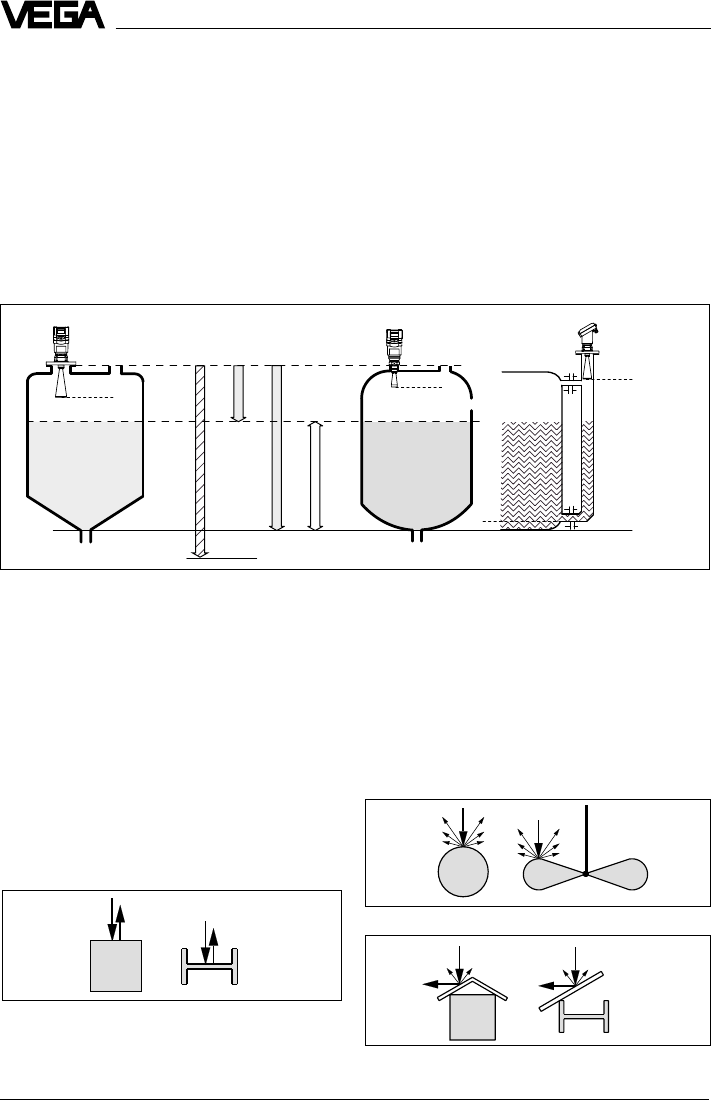
Measuring range (operating range) and max. measuring distance
Note: Use of the sensors for applications with solids is limited.
full
Meas. range
max. measuring distance 20 m
4 Mounting and installation
4.1 General installation instructions
Measuring range
The reference plane for the measuring range
of the sensors is the flange face or the seal
shoulder of the thread (VEGAPULS 42). For
measurements in surge or bypass tubes
(pipe antenna) the max. measuring distance
is reduced.
Keep in mind that in measuring environments
where the medium can reach the sensor
flange, buildup can occur on the antenna
which can cause measurement errors.
Note: The use of series 40 sensors for solids
is restricted.
Reference plane empty
Profile with smooth interfering surfaces cause large
false signals
Round profiles diffuse radar signals
A deflector causes signal scattering
max.
max.
max. filling
Interfering reflections
Flat obstructions and struts cause large
interfering reflections. They reflect the radar
signal with high energy density.
Round profile interfering surfaces scatter the
radar signals in all directions and thus cause
interfering reflections of lower energy density.
Hence, they are less critical than reflections
from a flat surface.
If flat obstructions in the range of the radar
signals cannot be avoided, we recommend
diverting the interfering signals with a deflec-
tor. Due to this scattering, the interfering
signals will be low in amplitude and so diffuse
that they can be filtered out by the sensor.
VEGAPULS 42 and 44 –4 … 20 mA 35
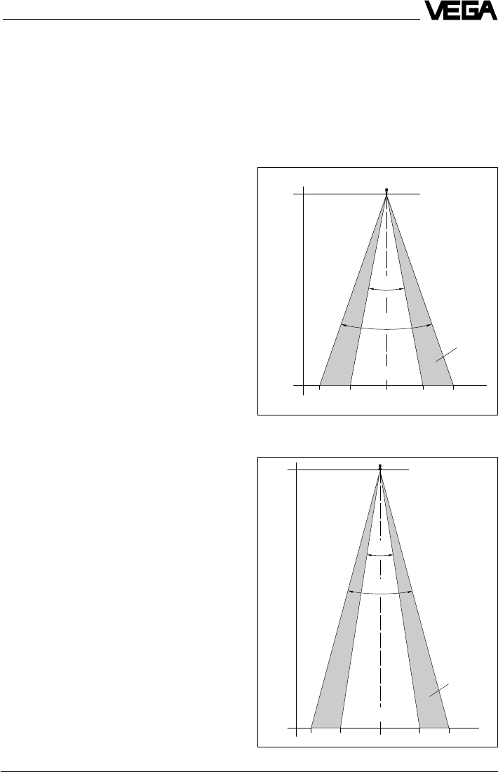
15 m
0 m
4,0 2,3 4,02,30
50%
m
25˚
18˚
100%
Emission cone of a VEGAPULS 42 with screw-on
antenna and with ø 40 mm horn
10 m
0 m
3,50 1,90 3,501,900
50%
m
30˚
22˚
100%
Meas.
distance
Emission cone of a DN 50 flange antenna
Meas.
distance
Mounting and installation
VEGAPULS 44 with
ø 48 mm horn
Emission cone and interfering reflec-
tions
The radar signals are focused by the an-
tenna system. The signals leave the antenna
in a conical path similar to the beam pattern
of a spotlight. The form and intensity of the
emission cone depend on the antenna used.
Any object in this beam cone causes a reflec-
tion of the radar signals. Within the first few
meters of the beam cone, tubes, struts or
other installations can interfere with the meas-
urement. At a distance of 6 m, the false echo
of a strut has an amplitude nine times greater
than at a distance of 18 m.
At greater distances, the energy of the radar
signal distributes itself over a larger area,
thus causing weaker echoes from obstruct-
ing surfaces. The interfering signals are
therefore less critical than those at close
range.
If possible, orient the sensor axis perpen-
dicularly to the product surface and avoid
vessel installations (e.g. pipes and struts)
within the 100 % area of the emission cone.
The following illustrations of the emission
beams are simplified and represent only the
main beam - a number of weaker beams also
exist. Therefore in practical application, the
antenna has to be oriented so that the lowest
possible false echo signal strength is
achieved. Only giving attention to a large
useful echo is not always adequate under
difficult measuring conditions.
In a difficult measurement environment,
searching for a mounting location with the
lowest possible false echo intensity will bring
the best results. In most cases, the useful
echo will then be present with sufficient
strength. With the adjustment software VVO
on the PC, you can have a look at the echo
image and optimise the mounting location
(see chapter "6.2 Adjustment with the PC –
Sensor optimisation – Echo curve“).
If possible, provide a "clear view“ to the
product inside the emission cone and avoid
vessel installations in the first third of the
emission cone.
Optimum measuring conditions exist when
the emission cone reaches the measured
product perpendicularly and when the emis-
sion cone is free of obstructions.
VEGAPULS 42
36 VEGAPULS 42 and 44 –4 … 20 mA
< 135 mm (DN 50)
< 210 mm (DN 80)
< 310 mm (DN 100, DN 150)
< 135 … 310 mm
(250 … 425 mm)
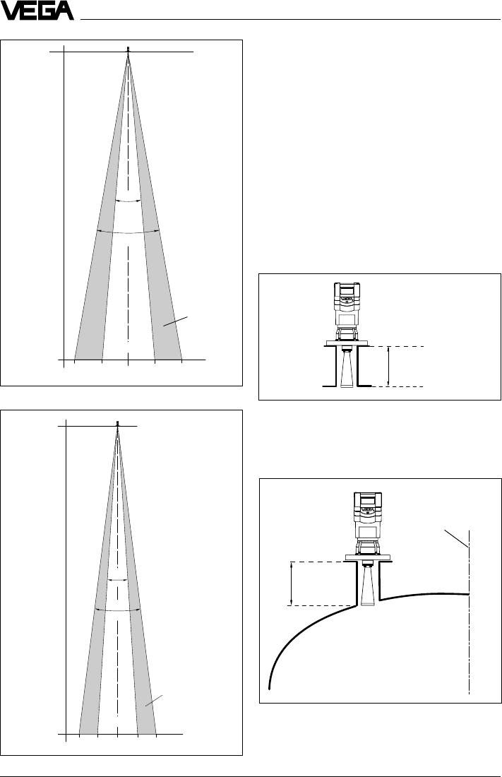
Emission cone of a DN 80 flange antenna
Meas. distance
Mounting and installation
20˚
10˚
20 m
0 m
3,0 1,7 3,0
1,7
0m
100%
50%
Mounting on DIN socket piece
When mounting on dished vessel tops, the
antenna length should at least correspond to
the length of the longer sockets.
Mounting on a dished vessel top; max. socket length
depending on flange size and, if applicable, on the
length of the antenna extension (see "3.3 Dimen-
sions“).
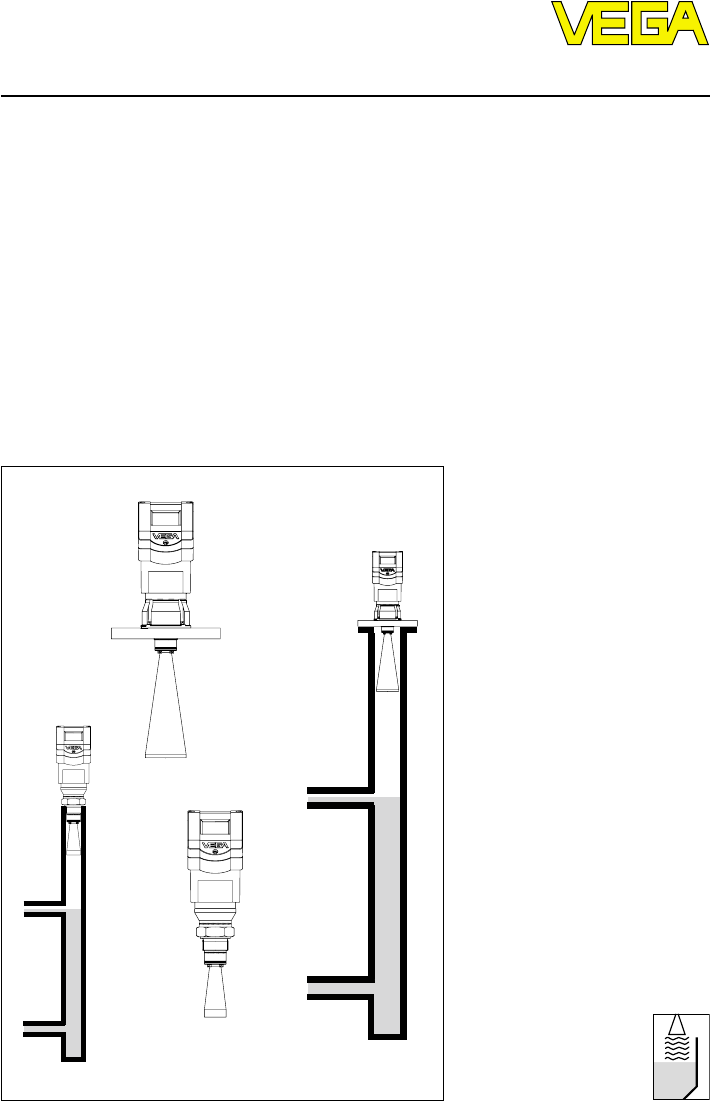
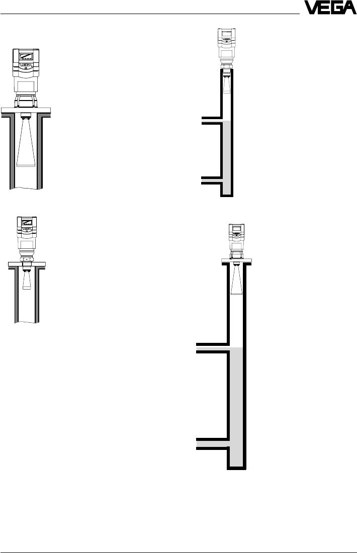
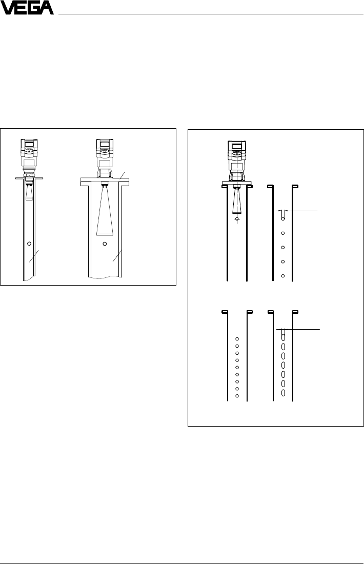
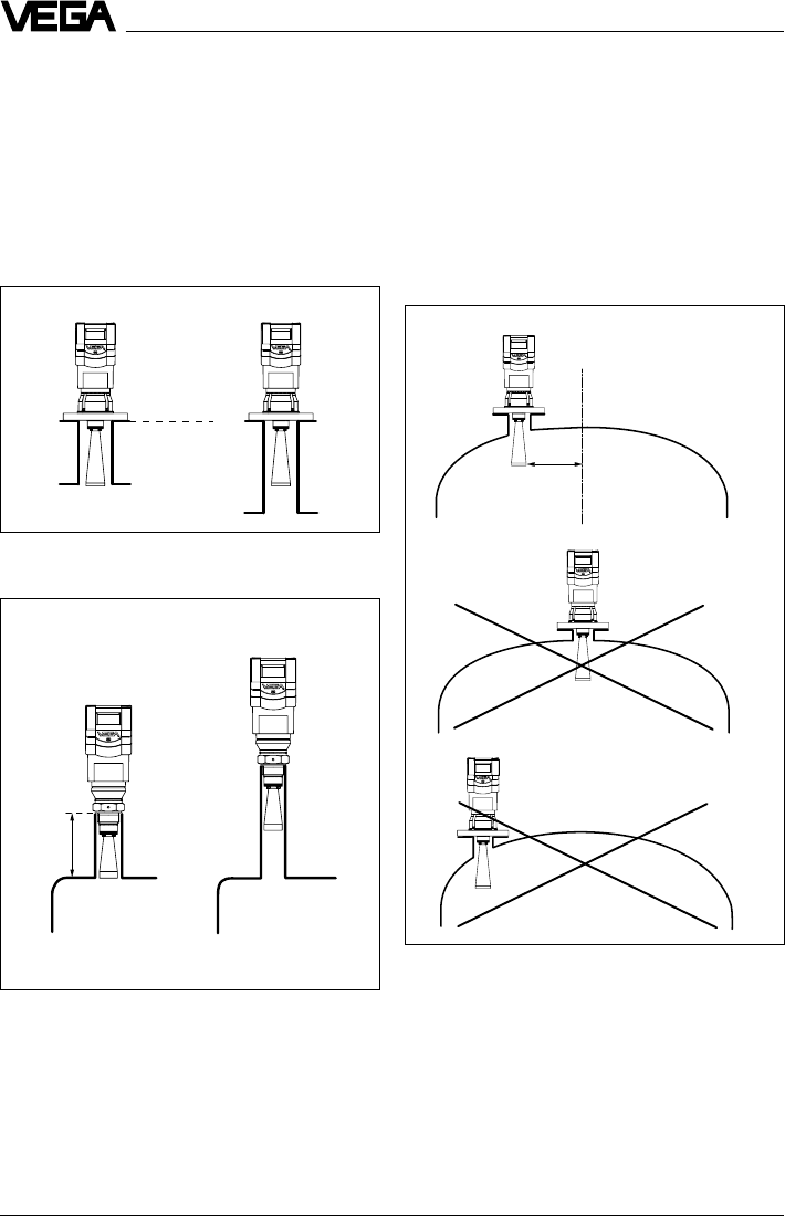
4.2 Measurement of liquids
Horn antenna
Horn antenna on DIN socket piece
In most cases, the mounting of radar sensors
is done on short DIN socket pieces. The
lower side of the instrument flange is the
reference plane for the measuring range. The
antenna should always protrude out of the
flange pipe.
When the DIN socket piece is longer, please
make sure that the horn antenna is not cov-
ered completely by the socket. It is better if
the antenna protrudes slightly out of the
socket.
Reference plane
20 m
0 m
2,5 1,3 2,51,30
50%
m
14˚
8˚
100%
Emission cone of a DN 100 and DN 150 flange antenna
VEGAPULS 44 with
ø 75 mm horn
Meas. distance
VEGAPULS 44 with
ø 95 mm horn
Vessel center or
symmetry axis
VEGAPULS 42 and 44 –4 … 20 mA 37
Mounting and installation
Mounting directly on the flat vessel top
Reference plane
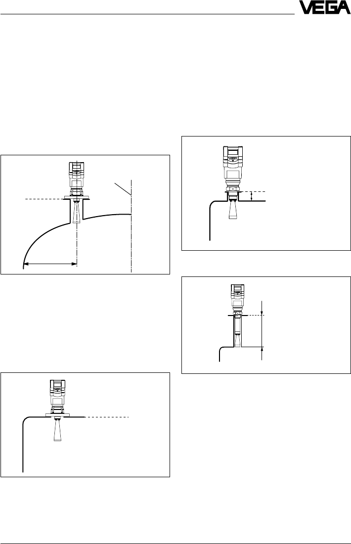
Mounting on dished tank ends
Reference plane
1/2 vessel radius
Horn antenna directly on the vessel top
If the stability of the vessel will allow it (sensor
weight), flat mounting directly on the vessel
top is a good and economical solution. The
top side of the vessel is the reference plane.
Screw-on antenna with antenna extension on socket
piece
£ 250 mm
Screw-on antenna
Screw-on antenna on socket piece
The screwed antenna is mainly used on small
vessels. The antenna fits on small vessel
openings down to 11/2“ socket.
The socket must not be longer than 140 mm
(when using the longer antenna, not longer
than 250 mm).
On dished tank ends, please do not mount
the instrument in the centre or close to the
vessel wall, but approx. 1/2 vessel radius from
the centre or from the vessel wall.
Dished tank ends can act as paraboloidal
reflectors. If the radar sensor is placed in the
focal point of the parabolic tank, the radar
sensor receives amplified false echoes. The
radar sensor should be mounted outside the
focal point. Parabolically amplified echoes
can be thereby avoided.
Screw-on antenna on socket piece 11/2“
£ 140 m
Reference plane
Vessel center or
symmetry axis
38 VEGAPULS 42 and 44 –4 … 20 mA
Mounting and installation
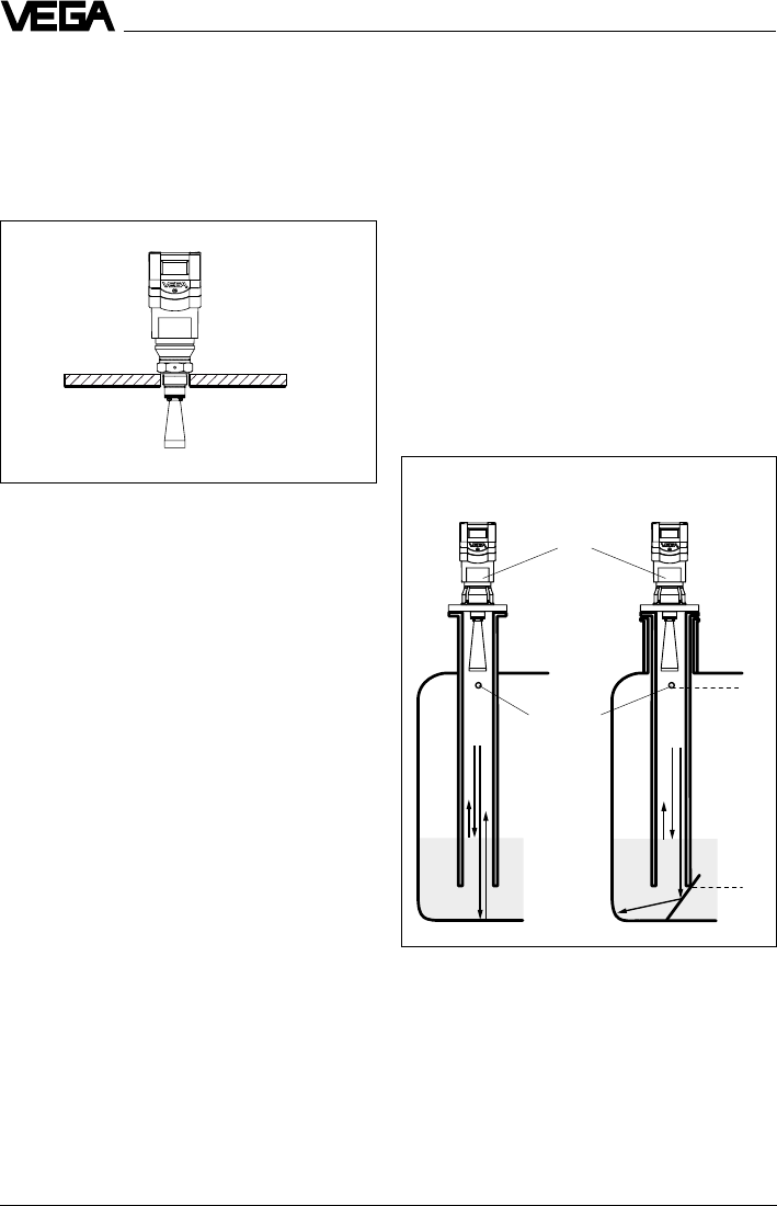
Pipe antenna systems in the tank
Type label
Vent hole
ø 5 … 10 mm
Surge pipe welded
to the tank
Surge pipe in the
socket piece
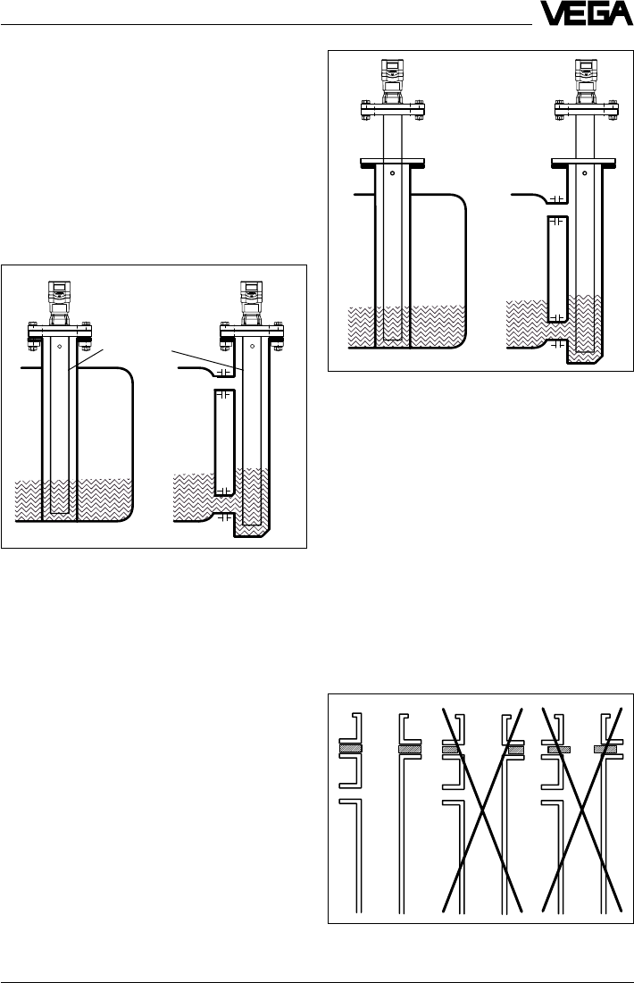
Surge pipes which are open at the bottom
must extend over the full measuring range
(i.e. down to 0% level), as measurement is
only possible within the tube.
4.3 Measurement in standpipe
(surge or bypass tube)
General instructions
Pipe antennas are preferred in vessels which
contain many installations, e.g. heating tubes,
heat exchangers or fast-running stirrers.
Measurement is then possible where the
product surface is very turbulent, and vessel
installations cannot cause false echoes.
Due to concentration of the radar signal within
the measuring tube, even products with small
dielectric constants (er= 1.6 up to 3) can be
reliably measured in surge or bypass tubes.
Please note the following instructions.
without deflector with deflector
min.
max.
Screw-on antenna directly in vessel opening
Screw-on antenna directly in vessel
opening
As an alternative to socket mounting, the
screw-on antenna can be mounted in round
vessel openings (holes).
VEGAPULS 42 and 44 –4 … 20 mA 39
100 %
0 %
> 300 mm
Mounting and installation
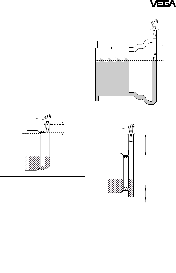
Tube flange system as bypass tube
Extended bypass tube on a vessel with turbulent
product movements
Type label
75 %
0 %
100 %
> 300 mm
Make sure the required upper vent hole in
the surge pipe is aligned with the sensor
type label.
As an alternative to a surge pipe in the ves-
sel, a pipe antenna system outside the ves-
sel in a bypass tube is also possible.
The surge and bypass tubes must generally
be made of metal. For plastic tubes, a
closed, conductive jacket is always required.
For metal tubes with plastic inner coating,
make sure that the thickness of the coating is
minimal (approx. 2 … 4 mm).
Align the sensor such that the type label lies
on one axis with the tube holes or the tube
connection openings. The polarisation of the
radar signal enables a considerably stabler
measurement with this alignment.
When mounting the sensor on a bypass tube
(e.g. on a previous floating or displacer unit),
the radar sensor should be placed approx.
300 mm or more from the max. level.
100 %
0 %
> 300 mm
300 ... 800 mm
Tube flange system as bypass tube
Type label
For products with small dielectric constants
(< 4), a much longer bypass tube should be
used than required by the lower tube con-
nection. Products with small dielectric con-
stants are partly penetrated by the radar
signals, so that the tube bottom delivers a
stronger echo than the product (when the
bypass tube is nearly empty). Due to the
extension of the lower tube end, sufficient
liquid will remain even when the vessel is
emptied.
40 VEGAPULS 42 and 44 –4 … 20 mA
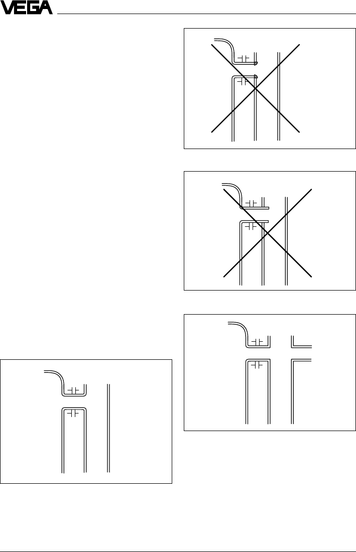
Optimum connection to the bypass tube
Strong welding on the tube connection
Tube connection protrudes
Additional connection to the bypass tube in one plane
Mounting and installation
With a liquid quantity of 300 … 800 mm in the
blind lower end of the tube, the portion of the
signal that penetrates the liquid and reflects
from the tube bottom is sufficiently damped -
the sensor can then easily distinguish it from
the echo of the liquid surface. If not enough
liquid remains, a deflection plate located at
the bottom of a vertical pipe can provide the
same function. It deflects the signal reflected
from the tube end sideways into the standard
tube opening.
Connections to the bypass tube
The connections to the bypass tubes must
be fashioned in such a way that only minimal
reflections are caused by the walls of the
connecting tubes. This is especially important
for the breather connection in the upper part
of the tube. Observe the following points:
•Use small openings for the connection.
•The diameter of the connecting tubes
should not exceed 1/3 of the bypass diam-
eter.
•The tube connections must not protrude
into the bypass.
•Big weld joints in the tubes should be
avoided.
•Additional connections to the bypass tube
must lie in the same plane as the breather
openings (superimposed or displaced by
180°).
VEGAPULS 42 and 44 –4 … 20 mA 41
Conducting tube in existing surge or bypass tube
Extended conducting tube
Flange connections on bypass tubes
Mounting and installation
Conducting tube
Use of conducting tubes
In case of very rough inner surfaces in exist-
ing bypass tubes (e.g. due to corrosion), or
very large bypass openings, the use of a
conducting tube inside the existing bypass
tube is recommended. This reduces the
noise level and increases reliability consider-
ably. The flange of the conducting tube can
be easily mounted as a sandwich flange
between vessel and sensor flange.
To increase the min. distance, the conducting
tube can protrude out of the surge or bypass
tube. For this purpose, a plain flange can be
welded at the required position on the out-
side of the extended conducting tube. In
both cases, an adequate breather hole must
be provided.
Seals on tube connections and tube ex-
tensions
Microwaves are very sensitive to gaps in
flange connections. If connections are made
without proper care, distinct false echoes as
well as increased signal noise can result.
Observe the following points:
•The seal used should correspond to the
tube inner diameter.
•If possible, conductive seals such as con-
ductive PTFE or graphite should be used.
•There should be as few seal positions as
possible on the conducting tube.
42 VEGAPULS 42 and 44 –4 … 20 mA
ø 5...10
ø 5...10
Mounting and installation
Openings in a surge pipe for mixing of inhomogene-
ous products
slightly inhomogeneous
liquids
inhomogeneous liquids
homogeneous
liquids
Pipe antenna with DN 50, DN 80, DN 100
DN 150
ø 50 ø 150
Standpipe measurement of inhomoge-
neous products
If you want to measure inhomogeneous prod-
ucts or stratified products in a surge pipe, it
must have holes, elongated holes or slots.
These openings ensure that the liquid is mixed
and corresponds to the liquid in the vessel.
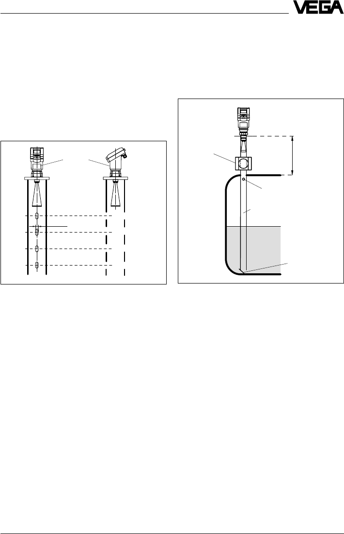
Adhesive products
For nonadhesive or slightly adhesive prod-
ucts, choose a surge pipe with a nominal
width of e.g. 50 mm. VEGAPULS 42 and 44
radar sensors with 24 GHz technology are
relatively insensitive to buildup in the tube.
Nevertheless, buildup must not be allowed to
plug up the tube completely.
For adhesive products, the use of a DN 80 to
max. DN 100 stand/surge pipe can enable
measurement in spite of buildup. Products
that cause excessive buildup cannot be
measured in a standpipe.
VEGAPULS 42 and 44 –4 … 20 mA 43
Mounting and installation
ø50
> 300 mm
Tube antenna system with ball valve cutoff in measur-
ing tube
Ball valve
Vent hole
The more inhomogeneous the measured
product, the closer the openings should be
spaced.
Due to radar signal polarisation, the holes or
slots must be positioned in two rows offset
by 180°.
The radar sensor must then be mounted so
that the type label of the sensor is aligned
with the rows of holes.
Every wider slot causes a false echo. The
slots should therefore not exceed a width of
10 mm, to keep the signal-to-noise ratio at a
minimum. Round slot ends are better than
rectangular ones.
Surge pipe with ball valve
If a ball valve is mounted in the surge pipe,
maintenance and servicing can be carried
out without opening the vessel (e.g. if it con-
tains liquid gas or toxic products).
Deflector
A prerequisite for trouble-free operation is a
ball valve throat that corresponds to the pipe
diameter and provides a flush surface with
the pipe inner wall. The valve must not have
any rough edges or constrictions in its chan-
nel, and should be located at least 300 mm
from the sensor flange.
ø 5...10
VEGAPULS 44: Rows of holes on one axis with the
type label
Type label
44 VEGAPULS 42 and 44 –4 … 20 mA
Mounting and installation
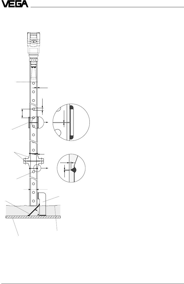
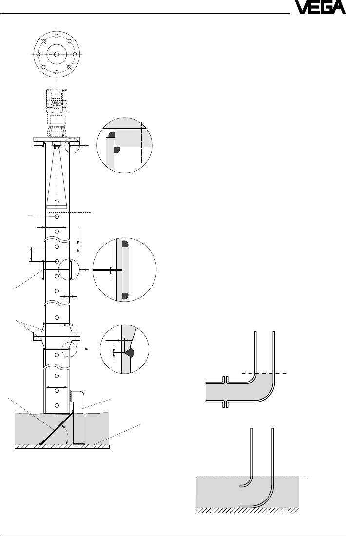
Guidelines for standpipe construction
Radar sensors for measurement on surge or
bypass pipes are routinely mounted in flange
sizes DN 50, DN 80, DN 100 and DN 150.
The radar sensor with a DN 50 flange forms a
functional measuring system only in conjunc-
tion with a measuring pipe.
The illustration on the left shows the construc-
tional features of a measuring pipe (surge or
bypass tube) as exemplified by a sensor
with DN 50 flange.
The measuring pipe must be smooth inside
(average roughness Rz £ 30). Use stainless
steel tubing (drawn or welded lengthwise) for
construction of the measuring pipe. Extend
the measuring pipe to the required length
with welding neck flanges or with connecting
sleeves. Make sure that no shoulders or
projections are created during welding. Be-
fore welding, join pipe and flange with their
inner surfaces flush and exactly fitting.
Avoid welding through the pipe wall. The pipe
must remain smooth inside. Roughness or
welding beads on the inner surfaces must be
carefully removed and burnished, as they
cause false echoes and encourage product
adhesion.
The following illustration shows the construc-
tional features of a measuring pipe as exem-
plified by a radar sensor with DN 100 flange.
Radar sensors with flanges DN 80,
DN 100 and DN 150 are equipped with a
horn antenna. With these sensors, a plain
welded flange can also be used on the sen-
sor end instead of a welding neck flange.
0 %
~45˚
ø 51,2
0,0...0,4
1,5...2
2,9
0,0...0,4
150...500
5...10
2,9...6
100 %
VEGAPULS 42
Connection
sleeves
Welding neck
flanges
Welding of the connect-
ing sleeve
Welding of the welding
neck flange
Meas. pipe fastening
Vessel bottom
Deflector
Min. product level to be
measured (0 %)
Deburr the
holes
G 11/2 A screwed
antenna
VEGAPULS 42 and 44 –4 … 20 mA 45
Mounting and installation
0 %
~45˚
ø 100,8
0,0…0,4
1,5…2
3,6
0,0…0,4
150…500
5…10
3,6
ø 95
2
100 %
VEGAPULS 44
Flange
DN 100
Connecting
sleeve
Welding neck
flanges
Welding of the plain
welded flange
Welding of the connect-
ing sleeves
Meas. pipe fastening
Vessel
bottom
Deflector
Deburr the
holes
If the vessel contains agitated products,
fasten the measuring pipe to the vessel bot-
tom. Provide additional fastenings for longer
measuring pipes.
When measuring products with lower dielec-
tric values (< 4), a part of the radar signal
penetrates the medium. If the vessel is nearly
empty, an echo is generated by the medium
and the vessel bottom. In some cases, the
vessel bottom generates a stronger signal
echo than the product surface. With a deflec-
tor on the measuring pipe end, the radar
signals are scattered. In nearly empty ves-
sels and products with low dielectric value,
the medium then generates a stronger echo
than the vessel bottom.
Thanks to the deflector, only the useful signal
is received in a nearly empty vessel - the
correct measured value is thus transmitted
and the 0 % level reliably detected.
Instead of a deflector, the standpipe or surge
pipe can be equipped with a quadrant pipe
at the end. This reflects the radar signals that
penetrate the medium diffusely to the side
and reduces strong echoes from the tube
end or vessel bottom.
Welding of the welding
neck flange
0 %
0 %
Quadrant pipe on the bypass tube end
Quadrant pipe on the standpipe end
46 VEGAPULS 42 and 44 –4 … 20 mA
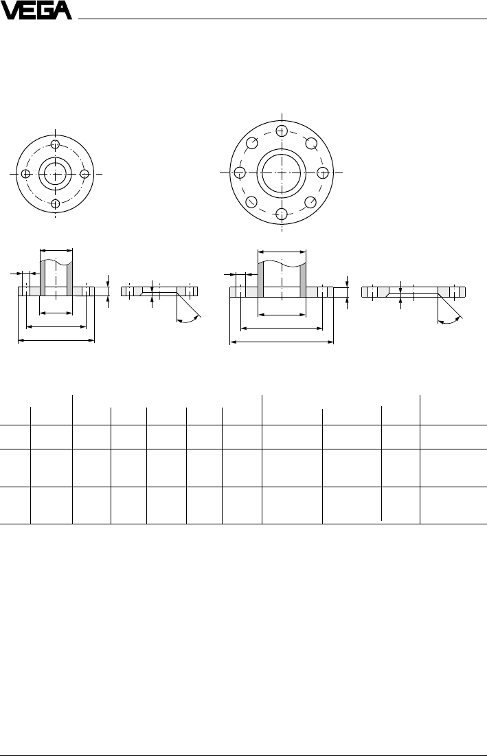
Examples of flange and pipe dimensions
The following shows a few examples of flanges and stainless steel pipes.
Plain welded flanges ND 6
D
b
e
45˚
D
b
e
45˚
kk
d
5
d
5
d
2
d
2
D
1
D
1
Tube Flange Screws Weight
NW D1d5D b e k No. Thread d2kg
80 88.9 90.2 200 20 7 160 8 M16 18 3.79
100 108 109.6 220 20 7 180 8 M16 18 4.20
114.3 115.9 4.03
150 159 161.1 285 22 7 240 8 M20 22 6.72
168.3 170.5 6.57
Mounting and installation
VEGAPULS 42 and 44 –4 … 20 mA 47
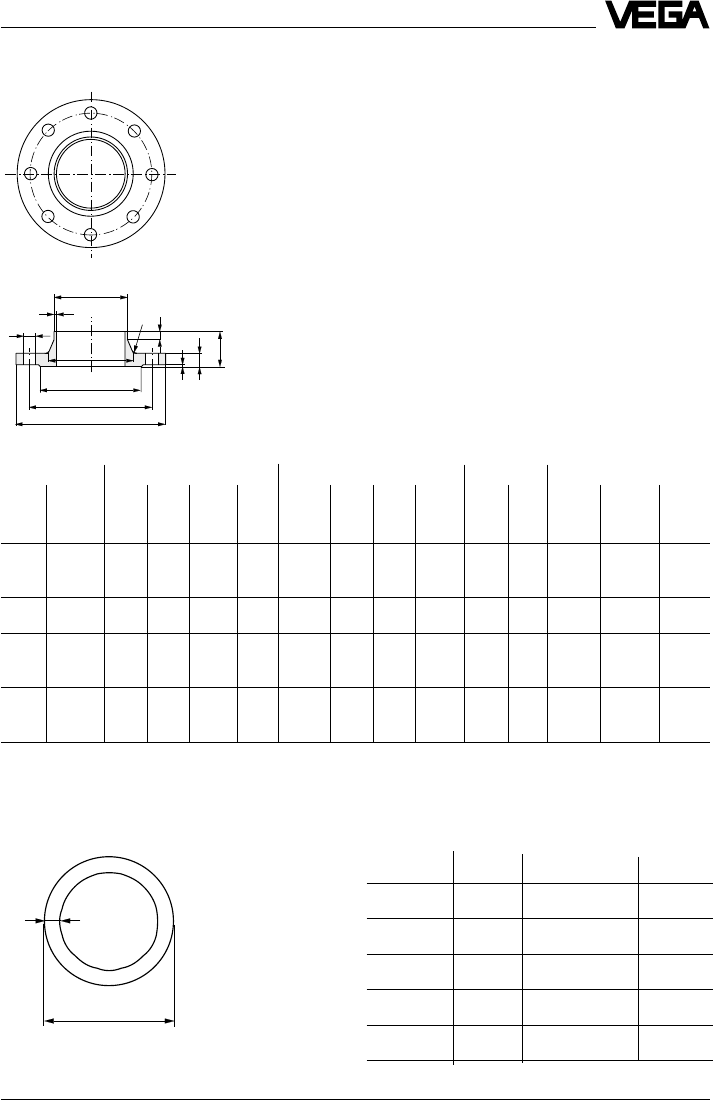
Tube Flange Neck Screws
NW D1Db k h
1D3sr H
2D4f No. Thread D2
50 57 165 18 125 45 72 2.9 6 8 102 3 4 M16 18
60.3 75
80 88.9 200 20 160 50 105 3.2 8 10 138 3 8 M16 18
100 108 220 20 180 52 125 3.6 8 12 158 3 8 M16 18
114.3 131
150 159 285 22 240 55 175 4.5 10 12 212 3 8 M20 22
168.3 184
Examples of pipe dimensions (drawn stainless
steel pipe)
d
s
D
f
b
D4
D2
s
H2
h1
D1
r
k
Welding neck flanges ND 16
Mounting and installation
D3
d (ø outer) s kg/m DN
57.00 2.90 3.493 50
88.90 3.20 7.112 80
108.00 3.60 9.411 100
114.30 3.60 9.979 100
159.00 4.50 17.409 150
48 VEGAPULS 42 and 44 –4 … 20 mA
Mounting and installation
4.4 False echoes
The installation location of the radar sensor
must be selected such that no installations or
inflowing material cross the radar impulses.
The following examples and instructions
show the most frequent measuring problems
and how to avoid them.
Vessel protrusions
Vessel forms with flat protrusions can, due to
their strong false echoes, greatly effect the
measurement. Shields above these flat pro-
trusions scatter the false echoes and guaran-
tee a reliable measurement.
Intake pipes, i.e. for the mixing of materials -
with a flat surface directed towards the sen-
sor - should be covered with a sloping shield
that will scatter false echoes.
Vessel protrusions (slope)
Vessel protrusions (intake pipe)
Correct Wrong
Correct Wrong
Vessel installations
Vessel installations such as, for example, a
ladder, often cause false echoes. Make sure
when planning your measuring location that
the radar signals have free access to the
measured product.
Vessel installations
Correct Wrong
Ladder
Ladder
Struts
Struts, like other vessel installations, can
cause strong false echoes that are superim-
posed on the useful echoes. Small shields
effectively hinder a direct false echo reflec-
tion. These false echoes are scattered and
diffused in the area and are then filtered out
as "echo noise“ by the measuring electronics.
Struts
Correct Wrong
Shields
VEGAPULS 42 and 44 –4 … 20 mA 49
75 %
0 %
100 %
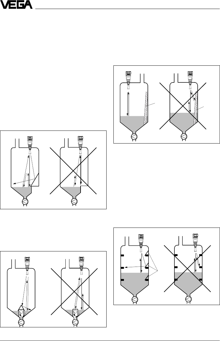
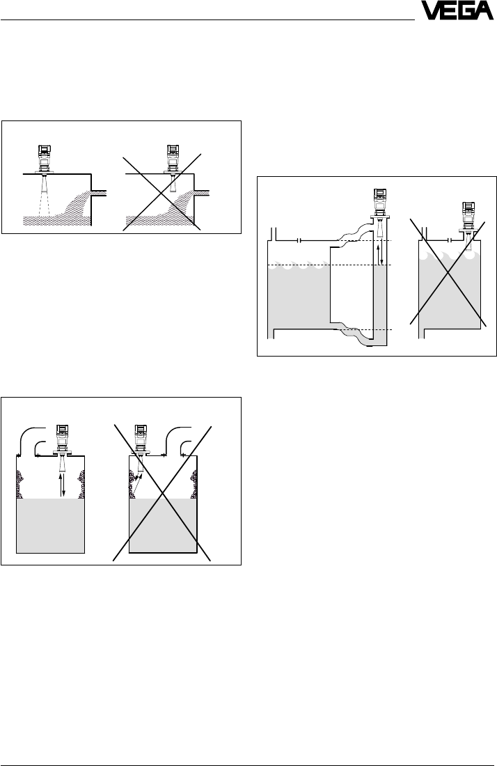
Strong product movements
Buildup
Correct Wrong
Strong product movements
Strong turbulences in the vessel, e.g. caused
by stirrers or intense chemical reactions, can
seriously interfere with the measurement. A
surge or bypass tube (see illustration) of
sufficient size always allows, provided the
product causes no buildup in the tube, a
reliable measurement even with strong turbu-
lence in the vessel.
Inflowing material
Correct Wrong
Mounting and installation
Inflowing material
Do not mount the instrument in or above the
filling stream. Ensure that you detect the
product surface and not the inflowing mate-
rial.
Buildup
If the sensor is mounted too close to the
vessel wall, buildup and adhesions of the
measured product to the vessel wall will
cause false echoes. Position the sensor at a
sufficient distance from the vessel wall.
Please also note chapter "4.1 General instal-
lation instructions“.
Correct Wrong
50 VEGAPULS 42 and 44 –4 … 20 mA
< 140 mm
(250 mm)
Mounting and installation
4.5 Common installation mistakes
Socket piece too long
If the sensor is mounted in a socket exten-
sion that is too long, false reflections are
caused, and measurement is hindered. Make
sure that the horn antenna protrudes out of
the socket piece.
Flange antenna: Correct and unfavourable socket
length
Flange antenna: Correct and unfavourable socket
length
Unfavour-
able
Correct Unfavourable
Wrong
Mounting on a vessel with parabolic tank top
Correct
~ 1/2
vessel
radius
Wrong
Correct
Parabolic effects on dished or arched
vessel tops
Round or parabolic tank tops act like a para-
bolic mirror on the radar signals. If the radar
sensor is placed at the focal point of such a
parabolic tank top, the sensor receives am-
plified false echoes. The optimum mounting
position is generally in the range of half the
vessel radius from the centre.
Reference plane
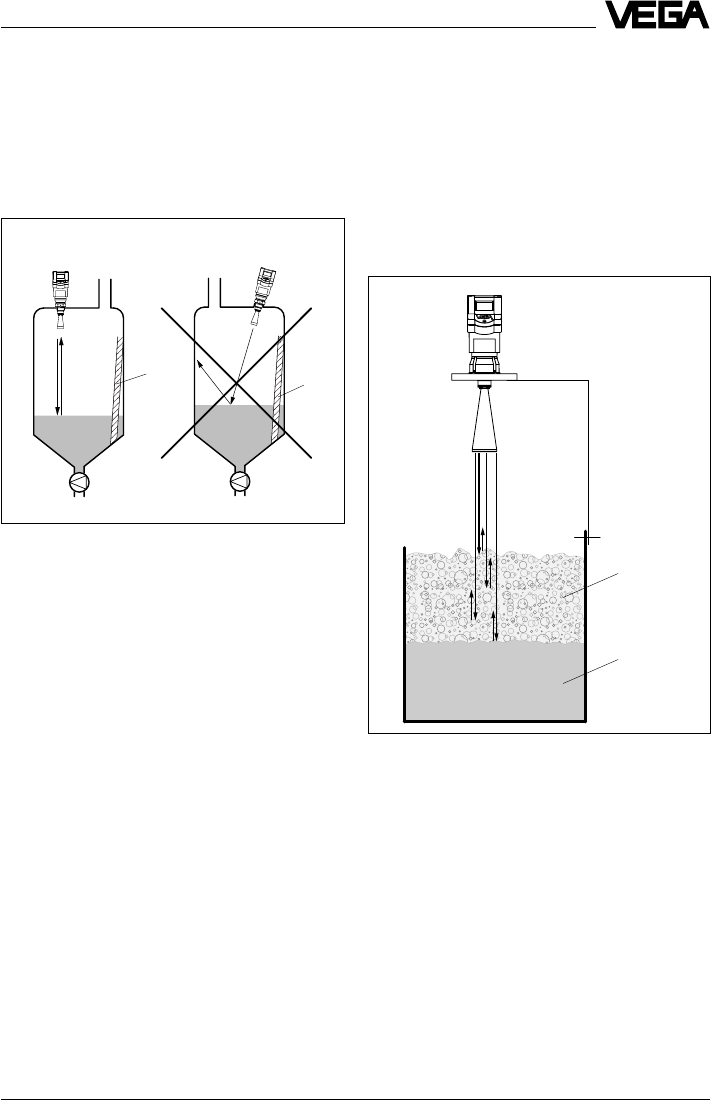
VEGAPULS 42 and 44 –4 … 20 mA 51
Mounting and installation
Sensor too close to the vessel wall
If the radar sensor is mounted too close to
the vessel wall, strong false echoes can be
caused. Buildup, rivets, screws or weld joints
superimpose their echoes onto the product
or useful echo. Please ensure sufficient dis-
tance of the sensor to the vessel wall.
In case of good reflection conditions (liquids
without vessel installations), we recommend
selecting the sensor distance so that there is
no vessel wall within the inner emission cone.
For products in less favourable reflection
environments, it is a good idea to also keep
the outer emission cone free of interfering
installations. Note chapter "4.1 General instal-
lation instructions“.
Wrong orientation to the product
Weak measuring signals are caused if the
sensor is not directly pointed at the product
surface. Orient the sensor axis perpendicu-
larly to the product surface to achieve opti-
mum measuring results.
Foam generation
Conductive foam is penetrated by the radar
signals to different depths and generates a
number of single (bubble) echoes. The sig-
nals in the foam are also damped, like heat
radiation that tries to penetrate styrofoam.
Thick, dense, creamy foam, and especially
conductive foam, on the product surface can
cause incorrect measurements.
Foam generation
conductive
foam
Liquid
Direct sensor vertically to the product surface
Correct Wrong
Ladder Ladder
Take measures to avoid foam, measure in a
bypass tube or use a different measuring
technology, e.g. capacitive electrodes or
hydrostatic pressure transmitters.
In many cases, VEGAPULS 54 radar sensors
with 5.8 GHz operating frequency reach
considerably better and more reliable meas-
uring results in foam applications than type
40 sensors with 24 GHz technology.
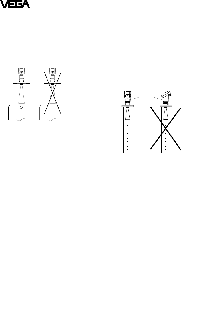
52 VEGAPULS 42 and 44 –4 … 20 mA
Pipe antenna: The surge pipe open to the bottom
must have a ventilation or equalisation hole on top
Correct Wrong
VEGAPULS 44 on the surge pipe: The sensor type
plate must be aligned with the rows of holes.
Type label
Correct Wrong
Mounting and installation
Installation mistakes in the standpipe
Pipe antenna without ventilation hole
Pipe antenna systems must be provided with
a ventilation hole on the upper end of the
surge pipe. A missing hole will cause false
measurements.
Wrong polarisation direction
When measuring in a surge pipe, especially if
there are holes or slots for mixing in the tube,
it is important that the radar sensor is aligned
with the rows of holes.
The two rows of holes (displaced by 180°) of
the measuring tube must be in one plane with
the polarisation direction of the radar signals.
The polarisation direction is always in the
same plane as the type label.

VEGAPULS 42 and 44 –4 … 20 mA 53
Electrical connection
5 Electrical connection
5.1 Connection and connection ca-
ble
Safety information
As a rule, do all connecting work in the com-
plete absence of line voltage. Always switch
off the power supply before you carry out
connecting work on the radar sensors. Pro-
tect yourself and the instruments, especially
when using sensors which do not operate on
low voltage.
Qualified personnel
Instruments which are not operated with
protective low voltage or DC voltage must be
connected only by qualified personnel.
Connecting and grounding
A standard two or four-wire cable (sensors
with separate supply) with max. 2.5 mm2 can
be used for connection. Very often the "elec-
tromagnetic pollution“ by electronic actuators,
energy cables and transmitting stations is so
considerable that the two-wire cable or the
four-wire cable should be shielded.
We recommend the use of screened cable.
Screening is also a good preventative meas-
ure against future sources of interference.
However, you must make sure that no
ground equalisation currents flow through the
cable screening. Ground equalisation cur-
rents can be avoided by ground potential
equalisation systems. When earthing on both
ends, it is possible to connect the cable
shield on one earth side (e.g. in the switching
cabinet) via a capacitor (e.g. 0.1 µF; 250 V)
to the earth potential. Use a very low-resist-
ance earth connection (foundation, plate or
mains earth).
Note!
In Ex applications, grounding on both ends is
not allowed due to potential transfer.
Ex protection
If an instrument is used in hazardous areas,
the respective regulations, conformity certifi-
cates and type approvals for systems in Ex
areas must be noted (e.g. DIN 0165).
Intrinsically safe circuits with more than one
active instrument (instrument delivering elec-
trical energy) are not allowed. Please note the
special installation regulations (DIN 0165).
Connection cable
Please note that the connection cables are
specified for the expected operating tempera-
tures in your systems. The cable must have an
outer diameter of 5 … 9 mm (1/2 up to 1/3 inch)
or Ex d housing 3.1 … 8.7 mm (0.12 … 0.34
inch). Otherwise the seal effect of the cable
entry will not be ensured.
Cables for intrinsically safe circuits must be
marked blue and must not be used for other
circuits.
Earth conductor terminal
On all VEGAPULS 44 sensors as well as the
series 42 sensors with metal thread, the earth
conductor terminal is galvanically connected
with the flange or the thread.
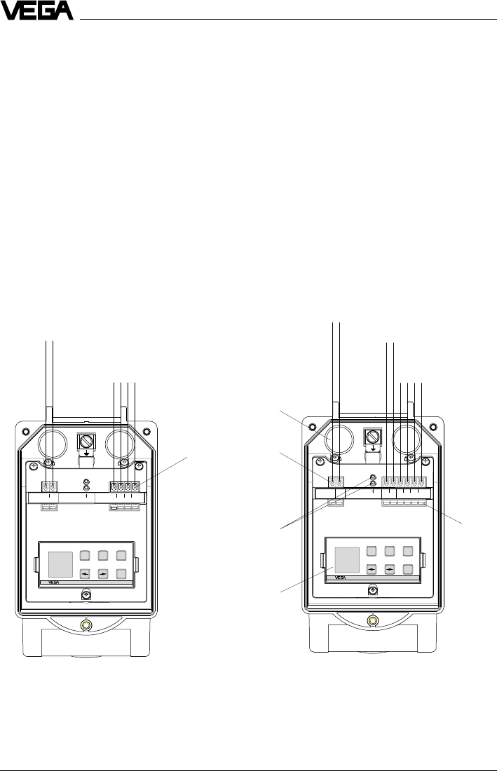
54 VEGAPULS 42 and 44 –4 … 20 mA
Electrical connection
+-
+-
2.23274
1
(+) L1
2
Communication
8765
Display
4-20mA
4-+3
N
-
OK
+ESC
Tank 1
m (d)
12.345
+-
Display
5678
Communication
2-
+
4-20mA
1
2.23272
-
OK
+ESC
Tank 1
m (d)
12.345
Power supply
4 … 20 mA (passive) 1)
To the indicating instrument in the
sensor lid or to the external indicating
instrument VEGADIS 50
Sockets for connection of
the HART® handheld or
the VEGACONNECT
Two-wire technology in
plastic housing
(loop powered)
Four-wire technology in
plastic housing
(separate supply)
Power supply
4 … 20 mA (active) 2)
Terminals
(max. 2.5 mm2
wire cross-section)
Opening
tabs
Pluggable
adjustment
module MINI-
COM
5.2 Connection of the sensor
After mounting the sensor at the measure-
ment location according to the instructions in
chapter "4 Mounting and installation“, loosen
the closing screw on top of the sensor. The
sensor lid with the optional indication display
can then be opened. Unscrew the sleeve nut
and slip it over the connection cable (after
removing about 10 cm of insulation). The
sleeve nut of the cable entry has a self-lock-
ing ratchet that prevents it from opening on
its own.
Now insert the cable through the cable entry
into the sensor. Screw the sleeve nut back
onto the cable entry and clamp the stripped
wires of the cable into the proper terminal
positions.
The terminals hold the wire without a screw.
Press the white opening tabs with a small
screwdriver and insert the copper core of the
connection cable into the terminal opening.
Check the hold of the individual wires in the
terminals by lightly pulling on them.
1) 4 … 20 mA passive means that the sensor
consumes a level-dependent current of
4 … 20 mA (consumer).
2) 4 … 20 mA active means that the sensor provides
a level-dependent current of 4 … 20 mA (current
source).
Version with plastic housing
Cable entry
M20 x 1.5
To the display in the lid or
the external indicating
instrument
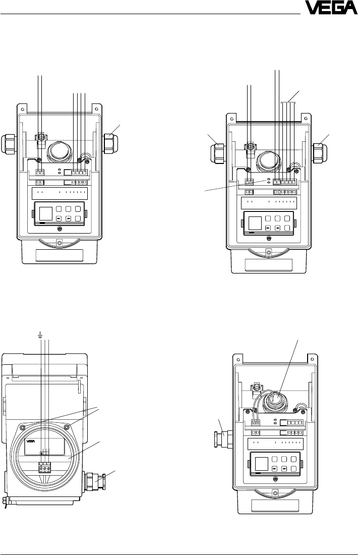
VEGAPULS 42 and 44 –4 … 20 mA 55
Electrical connection
-+
21
Shield
Supply: 20...36V DC/4...20mA HART
12
-+
ESC
ESC
+
-
OK
OK
1 2 C 567843
(+) (-)
L1 N
Commu-
nication
+-
4...20mA
Display
12 C 5 6 7 843
4 … 20 mA passive 1)
EEx d terminal compartment
(opening in Ex atmosphere not allowed)
Display terminal compartment with ad-
justment module
(opening in Ex area permitted)
Exd terminal compart-
ment
1/2“ NPT EEx d
diameter of the
connection cable
to the Exd
terminal com-
partment
3.1…8.7 mm
(0.12…0.34 inch)
Exd safe connection to the
Exd terminal compartment
1/2“ NPT EEx d
diameter of the
connection cable
3.1…8.7 mm
(0.12…0.34 inch)
Version with aluminium housing and pressure-tight encapsulated terminal com-
partment
Locking of the cover
ESC
ESC
+
-
OK
OK
-
+
-
+
1 2 C 567843
(+) (-)
L1 N
Commu-
nication
+-
4...20mA
Display
12 C 5 6 7 843
ESC
ESC
+
-
OK
OK
-
+
1 2 C 567843
(+) (-)
L1 N
Commu-
nication
+-
4...20mA Display
12 C 5 6 7 843
4 … 20 mA passive 1)
To the indicating instrument in the
sensor lid or to the external indicating
instrument VEGADIS 50
Two-wire technology
(loop powered)
Four-wire technology
Power supply
4 … 20 mA active 2)
M20 x 1.5
(diameter of the
connection cable
5…9 mm)
M20 x 1.5
(diameter of
the connection
cable
6…9 mm) M20 x 1,5
To the indicating
instrument in the sensor
lid or to the external
indicating instrument
VEGADIS 50
Version with aluminium housing
Sockets for connec-
tion of VEGACON-
NECT 2
(communication
sockets)
1) 4 … 20 mA passive means that the sensor
consumes a level-dependent current of 4 … 20 mA
(consumer).
2) 4 … 20 mA active means that the sensor provides
a level-dependent current of 4 … 20 mA (current
source).
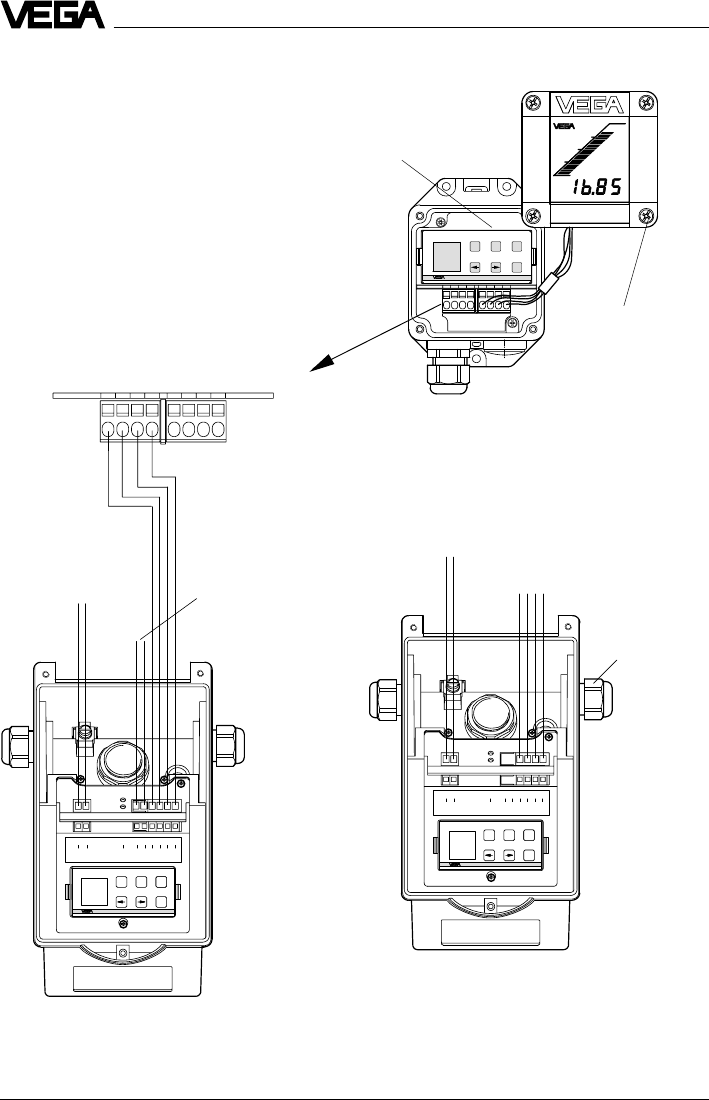
56 VEGAPULS 42 and 44 –4 … 20 mA
Electrical connection
SENSOR DISPLAY123 4 56 78
ESC
ESC
+
-
OK
OK
-
+
1 2 C 567843
(+) (-)
L1 N
Commu-
nication
+-
4...20mA Display
12 C 5 6 7 843
-+ESC
OK
Tank 1
m (d)
12.345
5.3 Connection of the external indi-
cating instrument VEGADIS 50
Loosen the four screws of the housing lid on
VEGADIS 50.
The connection procedure can be facilitated
by attaching the housing cover during con-
nection work with one or two screws on the
right side of the housing.
VEGADIS 50
ESC
ESC
+
-
OK
OK
-
+
1 2 C 567843
(+) (-)
L1 N
Commu-
nication
+-
4...20mA Display
12 C 5 6 7 843
Four-wire sensor in aluminium housing
(separate supply)
Two-wire sensor in aluminium housing
(loop powered)
Screws
OUTPUT
(to the sensor)
DISPLAY
(in the lid of the indicating
instrument)
4 … 20 mA
active
Power supply
Adjustment
module
4 … 20 mA
passive
to VEGADIS 50 or to the
display in the sensor lid
M20x1,5

VEGAPULS 42 and 44 –4 … 20 mA 57
Setup
VEGA signal conditioning instr Rx
VEGAMET 513, 514, 515, 602 50 … 100 Ohm
VEGAMET 614 no additional
VEGADIS 371 resistor
necessary
VEGAMET 601 200 … 250 Ohm
VEGASEL 643 150 … 200 Ohm
VEGAMET 513 S4, 514 S4
515 S4, VEGALOG EA card 100 … 150 Ohm
6.2 Adjustment with PC
PC on the sensor
For connection of the PC to the sensor, the
interface converter VEGACONNECT 2 is
required. It is plugged into the provided
CONNECT socket in the sensor.
Make sure that the pins of VEGACONNECT 2
are completely inserted into the sensor sock-
ets, as the new pins have a slightly increased
resistance to insertion. The pins should be
inserted up to a depth of approx. 13 mm to
15 mm.
PC on the signal cable
Connect the two-wire cable of
VEGACONNECT 2 to the signal cable of the
sensor. If the resistance of the systems (PLC,
current source etc.) connected to the signal
cable is less than 250 W, a resistor of
250 … 350 W must be connected to the signal
cable during adjustment (next page). The
digital signals superimposed on the signal
cable would otherwise be considerably
damped or even short-circuited due to insuf-
ficient system resistance, resulting in faulty
communication with the PC.
When using a sensor in conjunction with a
VEGA signal conditioning instrument, use a
communication resistor according to the
following schedule:
6 Setup
6.1 Adjustment methods
The radar sensors can be adjusted with
- PC (adjustment program VVO)
- with detachable adjustment module
MINICOM
- with HART® handheld.
The adjustment must be carried out with only
one adjustment device. If, for example, you
try the parameter adjustment with the MINI-
COM and the HART® handheld, the adjust-
ment will not work.
PC
The adjustment program VVO (VEGA Visual
Operating System) on the PC enables quick
and easy adjustment of radar sensors. The
PC communicates via the interface adapter
VEGACONNECT 2 with the sensor. During
the process, a digital adjustment signal is
superimposed on the signal and supply
cable. The adjustment can be carried out
directly on the sensor or at any desired loca-
tion along the signal cable.
Adjustment module MINICOM
With the adjustment module MINICOM you
adjust in the sensor or in the external indicat-
ing instrument VEGADIS 50. With a dialogue
text display and 6 keys, the module offers
the same adjustment functionality as the
adjustment software VVO.
HART® handheld
VEGAPULS 42 and 44 radar sensors, like
other HART® protocol-compatible instruments,
can be adjusted with the HART® handheld. A
manufacturer-specific DDD (Data-Device-
Description) is not required. The radar sen-
sors are adjusted with the HART® standard
menus. All main functions are accessible.
Functions that are rarely used, such as, for
example, the scaling of the A/D converter for
the signal output or the adjustment with me-
dium, are not possible or are blocked with
the HART® handheld. These functions must
be carried out with the PC or the MINICOM.
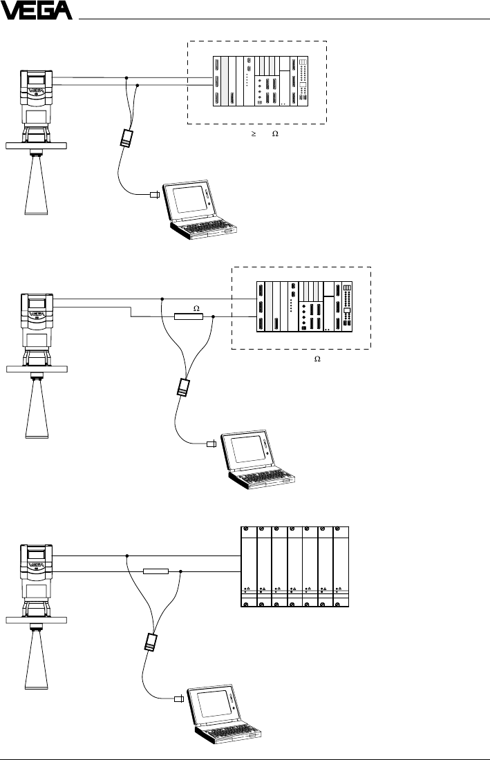
58 VEGAPULS 42 and 44 –4 … 20 mA
Rx
VEGAMET/VEGALOG
+
-
Ri 250
250
+
-
Ri < 250
Setup
PLC
PLC
VEGAPULS 42 and 44 –4 … 20 mA 59
Adjustment with the PC
In chapter "2.2 Configuration of measuring
systems“, connection of the PC to different
measuring systems is shown. The PC with
the adjustment program VVO version ³2.60
(VEGA Visual Operating) can be connected
to the
- sensor
- signal cable.
Note:
Please note that for adjustment of VEGAPULS
42 and 44 sensors, the adjustment program
VVO version 2.60 or higher is required.
In the following setup and adjustment instruc-
tions you will find information on the following
topics and adjustment points:
•
- configuration info
- create new/modify measurement loop
•
- measurement loop info
- adjustment
- conditioning/scaling
•
- meas. environment/operating range
- meas. environment/meas. conditions
- meas. environment/sound velocity
- echo curve
- false echo storage
•
- linearisation
- defining the linearisation curve by incre-
mental filling
- calculating the linearisation curve
- calculating a cylindrical tank
- parameter adjustment current output and
sensor display
•
Configuration and parameter adjust-
ment
During the setup of the sensor you are con-
fronted with two terms: "Configuration“ and
"Parameter adjustment“. The meas. system is
first set up with a configuration and then with
a parameter adjustment.
Setup
Configuration
The term "Configuration“ means the basic
adjustments of the meas. system. You inform
the meas. system about the application (level
measurement, gauge, distance …), the
measurement loop name and the DCS output
address of the sensors. The configuration
represents an electronic wiring and labelling
of your sensor or, in other words, telling the
system which sensor for what application
and where.
Parameter adjustment
After the configuration, you carry out the
parameter adjustment for each individual
sensor. This means adjusting the sensors to
the respective operating range and adapting
them to the specific application. You inform
the sensor which product distance (which
level) is "empty“ and which "full“. This is called
adjustment. Here you choose in which physi-
cal unit (volume, mass) and unit of measure-
ment (m3, gal, liters …) the adjusted
measured value should be outputted. In the
submenu "Sensor optimisation“, you inform
the sensor electronics about the actual envi-
ronment, such as e.g. quick changes of the
measured value, foam generation, gas strati-
fication, solid or liquid.
Before starting the setup:
Do not be confused by the many pictures,
adjustment steps and menus on the following
pages. Just carry out the setup with the PC
step by step and you will soon no longer
need the following instructions. Actions, like
entering a value or making a choice, are
indicated in the following by a large black
dot, like this:
•Choose …
•Start …
•Click to …
By this convention, the actions to be carried
out are clearly separated from supplemen-
tary information in the following adjustment
instructions.
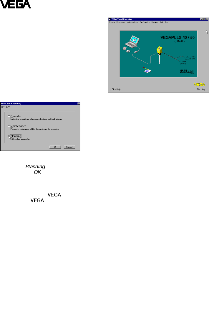
60 VEGAPULS 42 and 44 –4 … 20 mA
Setup
You have already connected the PC with the
adjustment software VVO to your measuring
system.
•Now switch on the power supply of the
connected sensor.
In the first 10 … 15 seconds the sensor starts
to draw a current of approx. 22 mA (self-test)
and immediately after, a level-proportional, i.e.,
distance-proportional current of 4 … 20 mA.
•Switch on the PC and start the adjustment
software VVO.
•Choose with the arrow keys or the mouse
the item " “ on the entrance screen
and click to " “.
You are asked for the user identification.
•Enter under name " “.
•Also enter " “ under password.
The adjustment program VEGA Visual Ope-
rating (VVO), called in the following VVO,
gets into contact with the connected sensor
…
… and indicates after a few seconds if and
with which sensor a connection exists.
Note:
When connecting the adjustment software
(VVO) to a sensor from which data has al-
ready been saved, you are asked if the
saved data should be transferred to the
sensor or if you want to transfer the sensor
data to the database of VVO (and the avail-
able data of the current sensor will be over-
written).
If you don’t get communication with the sen-
sor, check the following:
- Is the sensor being supplied with sufficient
voltage (min. 14 V)?
- When VEGACONNECT 2 is connected to
the signal cable, is the resistance of signal
cable, processing system and load resist-
ance 250 … 350 W?
- Did you inadvertently use a VEGACON-
NECT instead of the new VEGACON-
NECT 2?
- Did you connect VEGACONNECT 2 to
COM1 on the PC?
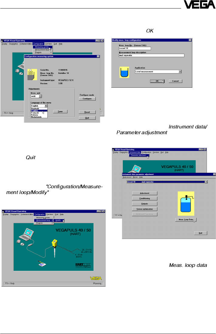
VEGAPULS 42 and 44 –4 … 20 mA 61
Parameter adjustment 1
Meas. loop data
•Click to the menu item "
“.
Setup
Configuration
Configuration info
•Choose the menu "Configuration/Measure-
ment loop“, to get further information on the
sensor type, the software version of the
sensor, the measuring unit, the measure-
ment loop designation etc.
•Click to " “.
Create new/modify measurement loop
•Click to the menu
. This is the first step in
setting up the sensor.
•Now enter in this menu whether a level, a
distance or a gauge should be measured
and click to " “.
In the menu "
Modify meas. loop configuration
“
you can give a name (e.g. vessel 10) and a
description (e.g. sludge separator) to the
measurement loop.
You are now in the initial menu window „
In-
strument data parameter adjustment
“.
•Click to the menu item " “.
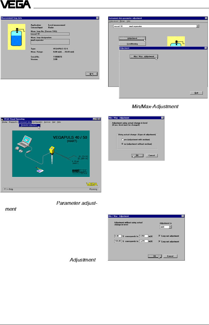
62 VEGAPULS 42 and 44 –4 … 20 mA
You can carry out the min./max. adjustment
with medium or without medium. Generally
you will carry out the adjustment without me-
dium. When you want to carry out the adjust-
ment with medium, you have to carry out the
min. adjustment with emptied vessel and the
max. adjustment with filled vessel.
In the window
“Measurement loop data”
, all
sensor data are displayed.
Adjustment
•Now choose the menu "
“.
In the menu "
Instrument data/Parameter ad-
justment
“ you now carry out all important
sensor adjustments. In the heading you now
see the previously entered measurement loop
name and the measurement loop description.
•Choose in the menu window "
Instrument
data parameter adjustment
“ " “.
Setup
•Click to " “.
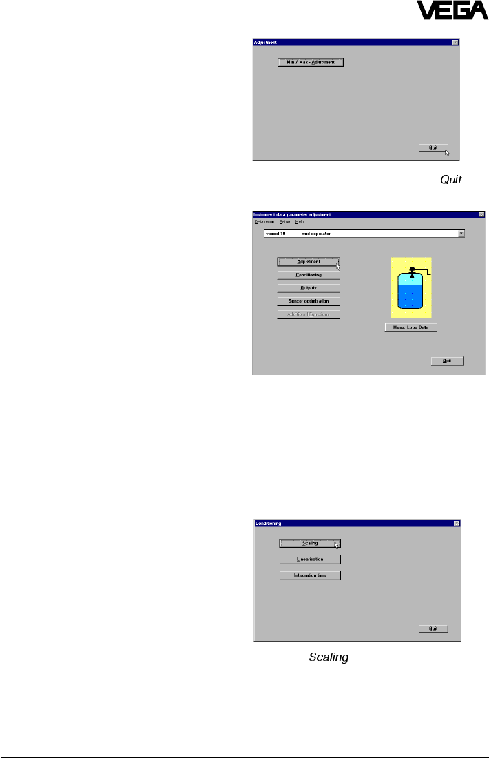
VEGAPULS 42 and 44 –4 … 20 mA 63
Setup
It is convenient and quick to carry out the
adjustment without medium, as shown in the
example.
•Choose if you want to carry out the adjust-
ment in
meters
(m) or in
feet
(ft).
•Enter a distance for the upper and lower
level and the extent of filling in % corre-
sponding to each distance.
In the example, the 0 % filling is at a product
distance of 5.850 m and the 100 % filling at a
product distance of 1.270 m.
•Confirm with "
OK
“.
For level detection outside the operating
range, the operating range must be cor-
rected respectively in the menu "
Sensor
optimisation/Operating range
“.
You are again in the menu "
Adjustment
“.
The sensor electronics has two characteris-
tics points from which a linear proportionality
between product distance and the percent-
age of filling of the vessel is generated.
Of course, the characteristics points must not
necessarily be at 0 % and 100 %, however
they should be as far apart as possible (e.g.
at 20 % and at 80 %). The difference be-
tween the characteristics points for the min./
max. adjustment should be at least 50 mm
product distance. If the characteristics points
are too close together, the possible measur-
ing error increases. Ideal would be to carry
out the adjustment, as shown in the example,
at 0 % and at 100 %.
In the menu "
Instrument data/Parameter ad-
justment/Conditioning/Linearisation
“, you can
enter later, if necessary, a correlation be-
tween product distance and % extent of filling
other than linear.
•Click in the menu "
Adjustment
“ to " “.
You are again in the menu window "
Instru-
ment data parameter adjustment
“.
Conditioning/Scaling
•Click to "
Conditioning
“.
The menu window "
Conditioning
“ opens.
•Click to " “.
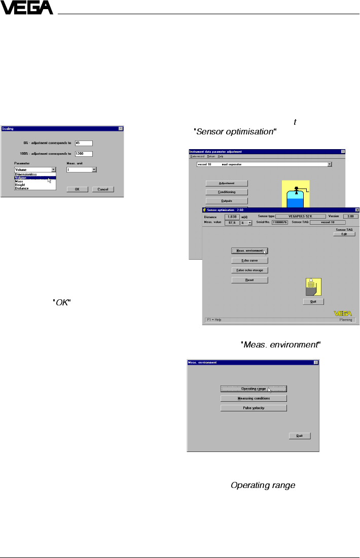
64 VEGAPULS 42 and 44 –4 … 20 mA
Sensor optimisation
In the menu "
Sensor optimisation
" you adapt
the sensor to the specific meas. environment.
Meas. environment/Operating range
•Choose in the menu window "
Instrument
data parameter adjustmen
“ the menu item
.
Setup
In the menu "
Scaling
“, you allocate a unit of
measurement and a numerical value to the
0 % and the 100 % values of the physical
quantity. You thereby inform the sensor, e.g.
that at 0 % filling there are still 45 liters and at
100 % filling 1200 liters in the vessel. The
sensor display then shows with empty vessel
(0 %) 45 liters and with full vessel (100 %)
1200 liters.
•First click to .
As physical quantity you can choose
"dimen-
sionless
(plain numbers),
volume, mass,
height and distance“
and assign an appro-
priate unit of measurement (e.g. l, hl). The
sensor display then shows the measured
value in the selected physical quantity and
unit.
•Save the adjustments in the menu "
Scaling
“
by clicking .
The adjustments are now transferred to the
sensor.
•Click in the menu window "
Meas. environ-
ment
“ to " “.
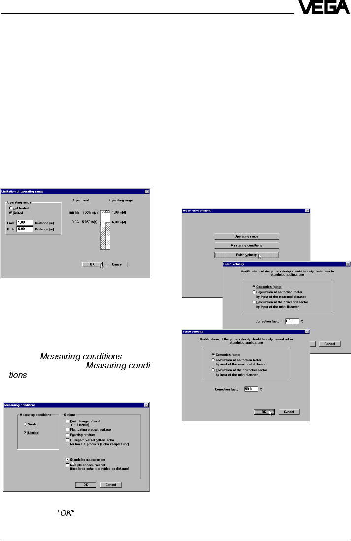
VEGAPULS 42 and 44 –4 … 20 mA 65
Setup
With the menu item "
Operating range
“, you
can define the operating range of the sensor
deviating from the "
Min/Max adjustment
“. By
default, the operating range corresponds
otherwise to the min./max. adjustment, i.e. the
span.
Generally, it is better to choose the operating
range approx. 5 % bigger than the adjusted
measuring range (span) determined by the
min./max. adjustment.
In the example:
- Min. adjustment to 1.270 m,
- Max. adjustment to 5.85 m.
In the example you would have set the oper-
ating range from 1 m to 6 m.
•Save the adjustments and quit the menu
window "
Limitation of the operating range“
.
Meas. environment/Meas. conditions
•Click to " “.
•In the menu window "
“ you click on the options correspond-
ing to your application.
After a few seconds during which the adjust-
ments are permanently saved in the sensor,
you are again in the window "
Meas. environ-
ment
“.
Meas. conditions/Pulse velocity
In the menu item "
Pulse velocity
“ adjustments
are only necessary when measuring in a
surge or bypass tube (standpipe). When
measuring in a standpipe, a shift of the run-
ning time of the radar signal (dependent on
the inner diameter of the standpipe) occurs.
To take this running time shift into account, it
is necessary to inform the sensor in the menu
of the tube inner diameter.
In the menu point "
Pulse velocity
“, it is addi-
tionally possible to set manually a correction
factor for the pulse velocity (light velocity) of
the radar signal.
•Confirm with .
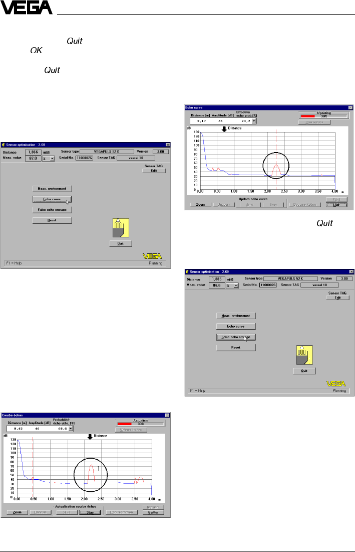
66 VEGAPULS 42 and 44 –4 … 20 mA
Setup
•If you want to make no adjustments, quit
this menu with " “.
•With " “ you save the adjustments made.
•Click in the menu window „
Meas. environ-
ment
“ to " “.
You are again in the menu window „
Sensor
optimisation
“.
Echo curve
In the next illustration, you see the echo curve
after optimum directing of the sensor to the
product surface (sensor axis perpendicular
to the product surface). The false echo, e.g.
caused by a strut, is now reduced by more
than 10 dB and will no longer influence the
measurement.
•Quit the menu "
Echo curve
“ with " “.
False echo storage
With the menu item "
Echo curve
“ in the menu
window "Sensor optimisation“, you can see
the course and the strength of the detected
radar echo. If, due to vessel installations, you
expect strong false echoes, a correction (if
possible) of the mounting location and orien-
tation (during simultaneous monitoring of he
echo curve) can help localise and reduce the
size of the false echoes. In the following illus-
tration, you see the echo curve with the false
echo nearly as large as the product echo
(before correction of the sensor orientation,
i.e. pointing it directly at the product surface).
With the menu item "
False echo storage
“ in
the menu "
Sensor optimisation
“, you can
authorise the sensor to save false echoes.
The sensor electronics then saves the false
echoes in an internal database and assigns
them a lower level of importance than the
useful echo.
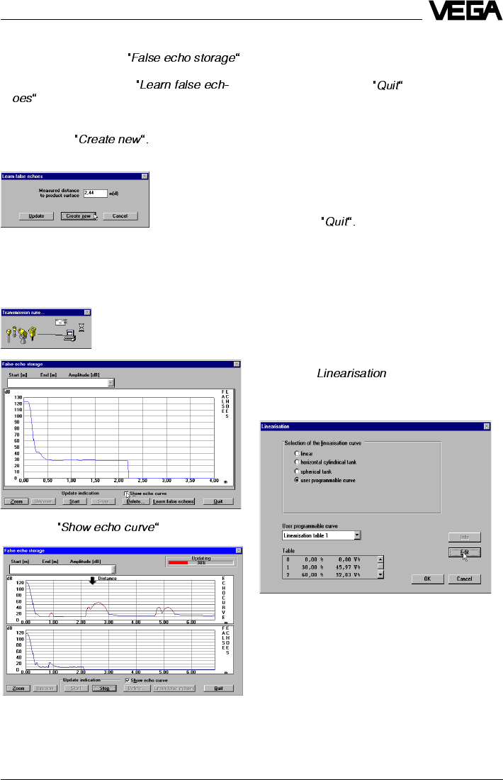
VEGAPULS 42 and 44 –4 … 20 mA 67
Setup
•Click in the menu window "
Sensor optimisa-
tion
“ to the menu item .
•Now click in the opening menu window
"
False echo storage
“ to
. The small window "
Learn false ech-
oes
“ opens.
•Enter here the verified product distance
and click to
You hereby authorise the sensor to mark all
echoes before the product echo as false
echoes. This prevents the sensor from erro-
neously detecting a false echo as level echo.
• Click to .
The echo curve and the false echo marking
are shown.
•Quit the menu with .
You are again in the menu window "
Sensor
optimisation
“.
With the menu item "
Reset
“ you reset all op-
tions in the menu "
Sensor optimisation
“ to
default.
•Quit the menu window "
Sensor optimisa-
tion
“ with
Linearisation
If, in your vessel, there is a correlation other
than linear between product distance and the
% value of the filling, choose the menu item
"
Linearisation
“ in the menu window "
Condi-
tioning
“.
•Click to " “.
The menu window "
Linearisation
“ opens.
A linear correlation between product distance
(in %) and filling volume (in %) has been
preset. Beside the two programmed lineari-
sation curves "
Cylindrical tank
“ and "
Spheri-
cal tank
“ you can also enter "
user
programmable curves
“. Linear means that
there is a linear correlation between level and
volume.
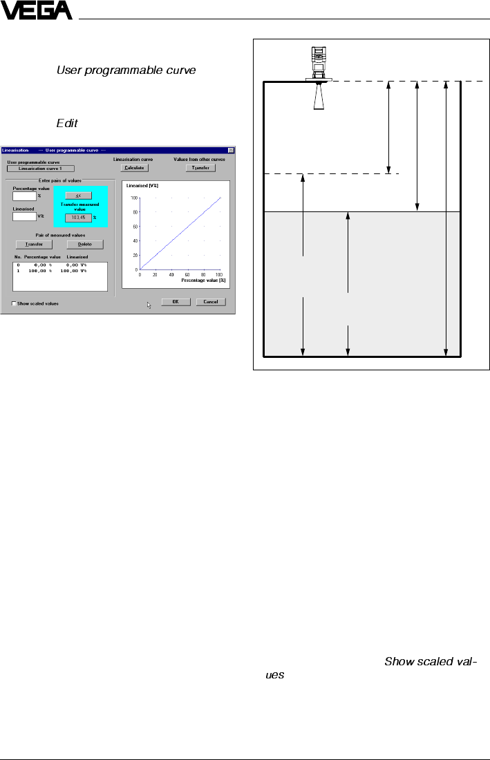
68 VEGAPULS 42 and 44 –4 … 20 mA
The distance (product distance) outputted
by the sensor, if you have chosen "
Distance
“,
is then:
5.85 – (4.58 • 0.9579) = 1.463 m.
If the index markers or value points of your
vessel are not known, you must gauge the
vessel incrementally or calculate it with the
vessel calculation program of VVO.
Defining the linearisation curve by incre-
mental filling
In the characteristics of the example, you see
four index markers or value pairs. There is
always a linear interpolation between the
index markers. The example vessel consists
of three cylindrical segments of different
height and diameter. The middle segment
has a considerably smaller diameter.
•Click in the check box "
“, to have the selected unit of measure-
ment displayed on the y-axis (left bottom
part in the menu window).
0 m
100 % at 1,27 m
1,463 m (95,79 %)
Span
4,58 m
(100 %)
4,387 m
(95,79 %)
0 % at 5,85 m
User programmable linearisation curves
•Click to " “to
enter your own vessel geometry or a user
programmable filling curve.
•Click to " “.
The user-programmable linearisation curve is
generated by index markers. Each index
marker consists of a value pair. A value pair
is composed of a value "
Linearised
“ and a
value "
Percentage value
“.
“Percentage value”
represents the percentage value of level.
"
Linearised
“ represents the percentage of
vessel volume at a certain percentage value
of the level.
In the field "
Transfer measured value
“ the
current level as a percentage of the adjusted
span is displayed. The measuring span has
already been adjusted with the min./max.
adjustment. In the example, the span is
4.58 m and is between 5.85 m (empty) and
1.27 m (full), see the following illustration.
5.85 m meas. distance correspond to 0 %
level. 1.27 m meas. distance correspond to
100 % level. The span is therefore 4.58 m
(5.85 m – 1.27 m = 4.58 m).
A percentage value of 95.79 % then means
that 4.387 of the adjusted span (4.58 m) has
been reached:
4.58 • 0.9579 = 4.387 m.
Setup
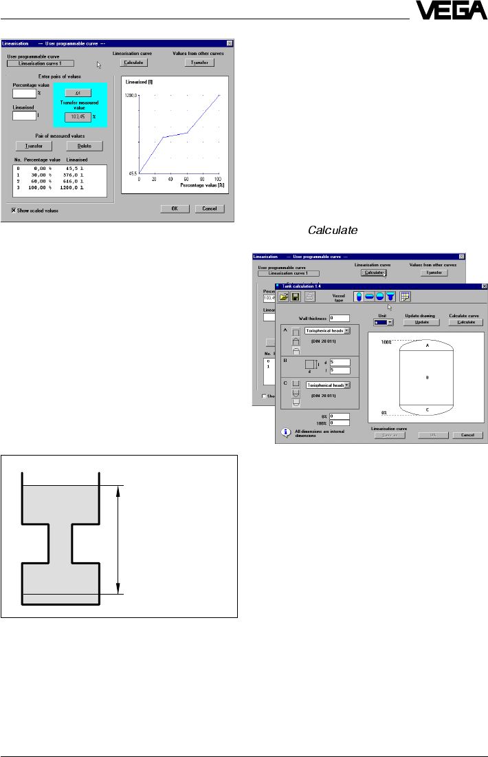
VEGAPULS 42 and 44 –4 … 20 mA 69
Max.
Min.
100 % (1.270 m) correspond
to 1200 liters
Span (4.58 m)
0 % (5.850 m) correspond to
45 liters
Index marker 1 is at 0 % filling (
percentage
value [%]
), corresponding in the example to
an actual distance to the product surface of
5.850 m (empty vessel). The volume value is
45 liters (fluid remaining in the vessel). Index
marker 2 is at a filling level of 30 % (30 % of
the meas. distance of 1.270 m … 5.850 m). At
a filling level of 30 %, there are 576 liters in
the vessel (in our example).
Index marker 3 is at a filling level of 60 %. At
this filling level there are 646 liters in the ves-
sel.
Index marker 4 is at a filling level of 100 %
(product distance 1.270 m), where 1200 liters
are in the vessel.
Setup
Max. 32 index markers can be entered per
linearisation curve (value pairs).
Calculating the linearisation curve
(use previous tank example)
In the menu window "
Linearisation -- user
programmable curve --
“ you can start the
vessel calculation program. With the vessel
calculation program you can calculate (using
dimensions from the technical drawings of
the vessel) the correlation of filling height to
filling volume. If the curve is defined this way,
gauging by incremental filling is not neces-
sary - your sensor can then output volume as
a function of level.
•Click to " “.
The tank calculation program starts. In the
top left corner you choose the vessel type
(upright tank, cylindrical tank, spherical tank,
individual tank form or matrix). When choos-
ing matrix, you can enter a user programma-
ble linearisation curve by means of index
markers. This corresponds to the entering of
value pairs (linearisation points), as previ-
ously described.
In the following example, the tank calculation
program calculates the linearisation curve of
a vessel corresponding to the vessel in the
previous gauging example.
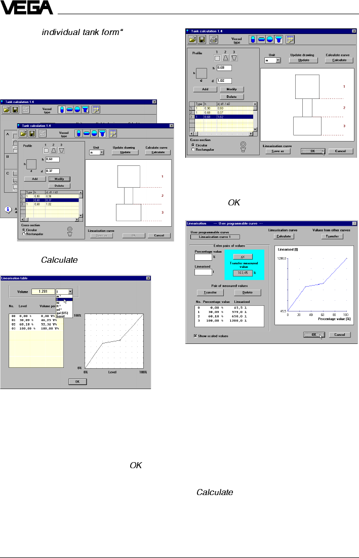
70 VEGAPULS 42 and 44 –4 … 20 mA
You are again in the menu window "
Tank
calculation
“.
•Click to „ “ to save the tank calculation.
You are again in the menu window "
Linearisa-
tion -- user programmable curve --
“. The
volume percentages, with the corresponding
level percentages, are shown as scaled
values (liters in this example), if you have
clicked in the check box in the bottom left
corner of the window.
Calculate cylindrical tank
•Click in the menu window "
Linearisation --
user programmable curve --
“ to
"“ and in the menu window "
Tank
calculation
“ to the symbol for cylindrical
tanks.
Setup
•Click to " and choose
three round tank segments with the dimen-
sions 0.88 m • 0.9 m (height by diameter),
0.66 m • 0.47 m and 0.66 m • 1.12 m (this
tank form corresponds to the tank form of
the gauging example).
•Click to " “.
After a short calculation time, the levels as a
percentage of span and the corresponding
volume percentages are shown. The
outputted curve shows this correlation in a
diagram.
•Quit the linearisation table with „ “.
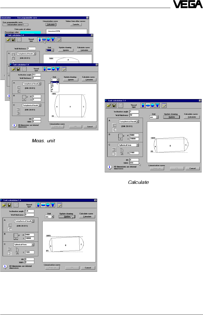
VEGAPULS 42 and 44 –4 … 20 mA 71
Setup
•Choose the " “, e.g. mm, that
should apply to the entered vessel dimen-
sions.
The following example shows how to enter a
cylindrical tank that is inclined by 3° and has
a cylinder length of 10000 mm and a diam-
eter of 5000 mm. The cylindrical tank has a
1500 mm wide, spherical form at the right
end and a dished tank form at the left.
In the bottom left corner in the menu window
"
Tank calculation
“ you find the information "
All
dimensions are internal dimensions
“.
The entering of a wall thickness is only nec-
essary for the calculation of the dished boiler
end as its mathematical calculation is based
on the outer dimension.
The calculation program calculates by means
of the vessel inner dimensions the vessel
volume. Above the information
"All dimensions
are internal dimensions
“, you will find two
fields with the percentage values 0 % and
100 %. Here you can shift the 100 % line or
the 0 % line. In the example, the 100 % filling
line was defined at a distance of 650 mm
from the upper vessel edge (inside).
•Click to " “.
You will get the calculated linearisation table
after a short calculation time. By means of 32
linearisation points, a function correlating
vessel volume to filling height is outputted.
The example vessel has a filling of 216561
liters at the 100 % line or of 216.6 m3. It is
possible to output the volume value in bar-
rels, gallons, cubic yards or cubic feet.
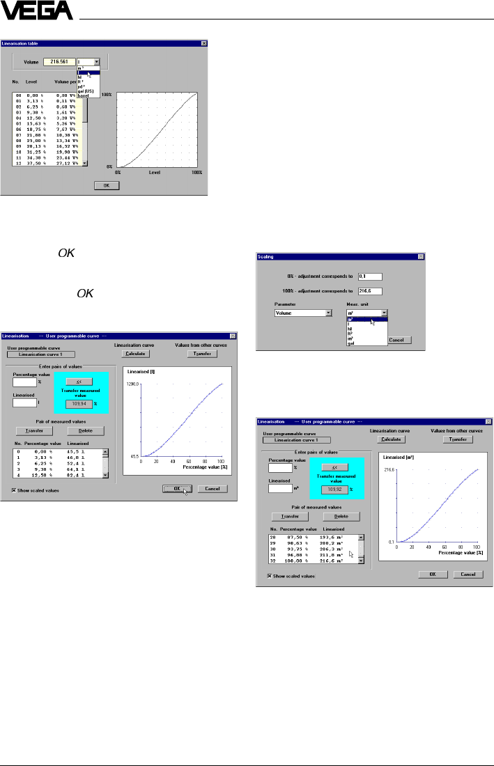
72 VEGAPULS 42 and 44 –4 … 20 mA
In the menu "
Scaling
“ (Instrument data/Condi-
tioning/Scaling) you entered earlier that at
0 % filling there are 45 liters in the tank and at
100 % filling 1200 liters. The geometry of the
calculated cylindrical tank was accordingly
scaled down to a size that indeed evaluates
to a volume of only 1200 liters. The modified
linearisation curve was then applied to the
volume data that you entered in the menu
"
Scaling
“.
If the true content of the calculated vessel
should be outputted, the volume that was
determined by the tank calculation program
must be entered in the menu "
Scaling
“.
The sensor then outputs the actual filling
volume calculated from the entered vessel
dimensions.
Setup
There is a linear interpolation between the
linearisation points.
•Click to " “ and you are again in the
menu window "
Tank calculation
“.
•Again click in the menu window "
Tank cal-
culation
“ to " “ and you are in the lineari-
sation menu.
Here the calculated linearisation curve is
again outputted. The volume information
under "
Linearised
“ now no longer corre-
sponds to the calculated volume of the tank
calculation program.
Why?
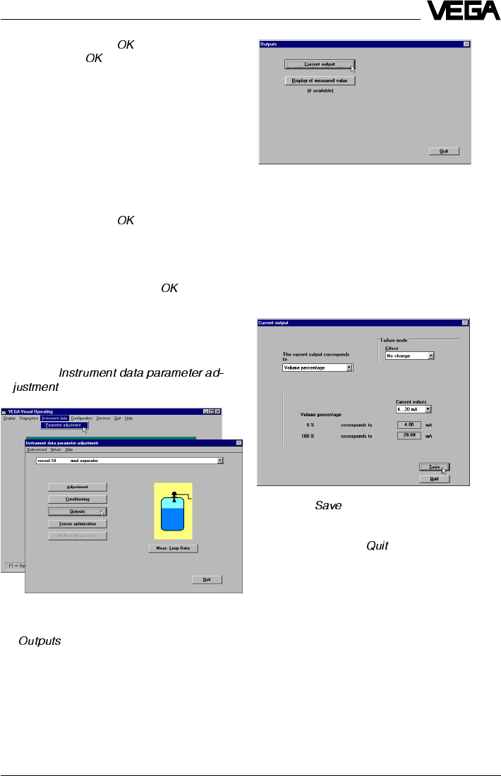
VEGAPULS 42 and 44 –4 … 20 mA 73
•Quit the menu with " “.
•Confirm with " “ and your individual
linearisation curve is saved in the sensor.
Again in the menu window "
Conditioning
“, you
can enter with the menu item "
Integration
time
“ a measured value integration. This is
recommended for agitated product surfaces,
to prevent rapid fluctuation of the output
signal and the measured value indication.
The standard setting is an integration time of
0 seconds.
•Quit the menu with " “.
You are again in the menu window "
Instru-
ment data parameter adjustment
“.
•Quit the menu window with " “.
Parameter adjustment for current out-
put and sensor display
•Choose "
“.
•Choose in the menu window "
Instrument
data parameter adjustment
“ the menu item
„ “.
Setup
You are in the menu window "
Outputs
“.
Parameter adjustment current output
With the menu item "
Current output
“ you
choose the menu window "
Current output
“.
Here you can adjust the signal condition of
the 4 … 20 mA output signal.
•Click to " “, if you have made adjust-
ments in this menu window.
•If the adjustments should remain un-
changed, click to " “.
You are again in the menu window "
Outputs
“.
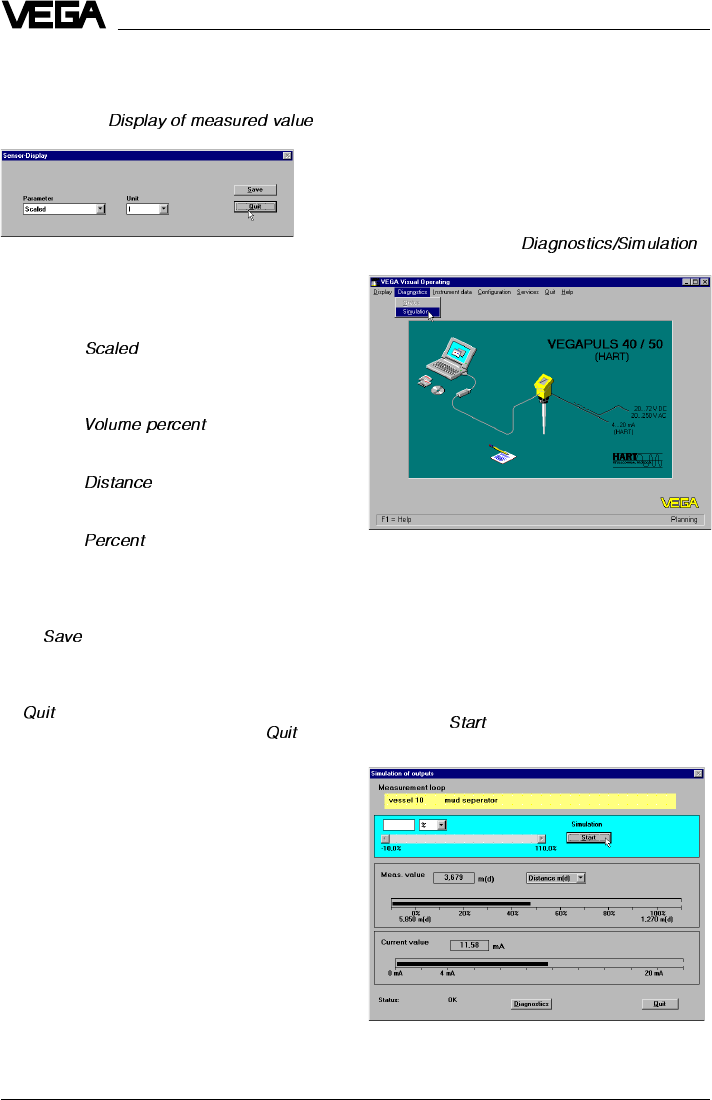
74 VEGAPULS 42 and 44 –4 … 20 mA
The menu window "
Display of measured
value
“ opens. In this menu window you can
also set the filling height in the vessel or the
signal current and the indication display to
any value (simulate measured value).
First of all, the actual measured value and the
signal current are displayed.
•Click to " “in the turquoise window
segment.
Interface parameter adjustment
and
Display of measured value
See manual "VEGA Visual Operating“.
Simulation
•Click to the menu " “.
Setup
The menu window "
Sensor-Display
“ opens.
Here you can once again adjust the sensor
display.
•Choose " “, if the display should
show your previous adjustments. In the
example a level of 45 … 1200 liters would
be displayed.
•Choose " “, if the level of
45 … 1200 liters should be displayed as
percentage value of 0 … 100 %.
•Choose " “, to have the actual
distance to the product surface displayed
(in m).
•Choose "“, if you want to have the
product distance from 1.270 to 5.850 m
displayed as percentage value of
0 … 100 %.
With " “ the adjustment is transferred to
the sensor.
•Click in the window "
Sensor-Display
“ to
"“.
•Click in the window "Outputs“ to " “.
You are again in the menu window "
Instru-
ment data parameter adjustment
“.
Parameter adjustment sensor display
•Click in the menu window "
Outputs
“ to the
menu item " “.
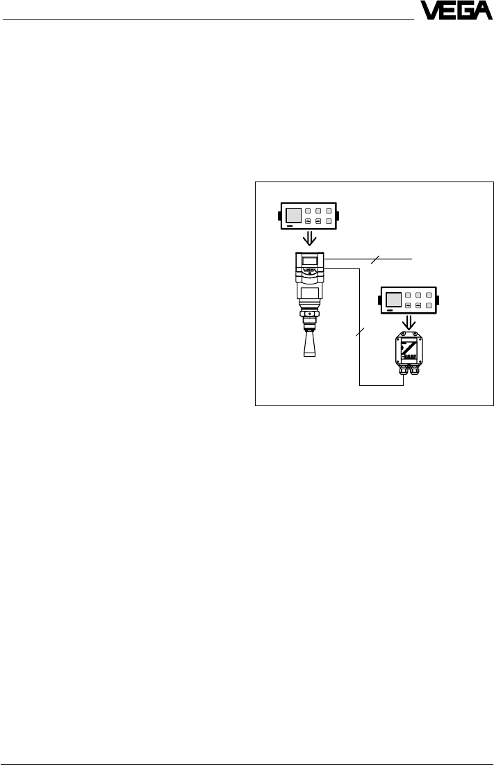
VEGAPULS 42 and 44 –4 … 20 mA 75
2
4
4 ... 20 mA
-+
ESC
OK
Tank 1
m (d)
12.345
-+
ESC
OK
Tank 1
m (d)
12.345
6.3 Adjustment with adjustment
module MINICOM
As with the PC, you can also adjust the sen-
sor with the small, detachable adjustment
module MINICOM. The adjustment module is
simply plugged into the sensor or into the
external indicating instrument (optional).
For the adjustment with adjustment module,
all sensor versions (adjustment options), as
with the PC and the adjustment program
VVO, are available. There are some differ-
ences, however, with MINICOM. It is not
possible to enter your own linearisation
curve.
You carry out all adjustment steps with the 6
keys of the adjustment module. A small dis-
play shows you, apart from the measured
value, a short message on the menu item or
the entered value of a menu adjustment.
The volume of information of the small display,
however, cannot be compared with that of the
adjustment program VVO, but you will soon
get used to it and be able to carry out your
adjustments quickly and efficiently with the
small MINICOM.
Setup
The grey scroll bar becomes active. With this
scroll bar you can change the measured
value to any value in the range of
-10 % … 110 % and thereby simulate the
filling or emptying of the vessel. In the input
box of the turquoise window cutout you can
enter any percentage value of filling.
Note on the simulation mode:
One hour after the last simulation adjustment,
the sensor automatically returns to standard
operating mode. The display of measured
value flashes during simulation.
Backup
See manual "VEGA Visual Operating“.
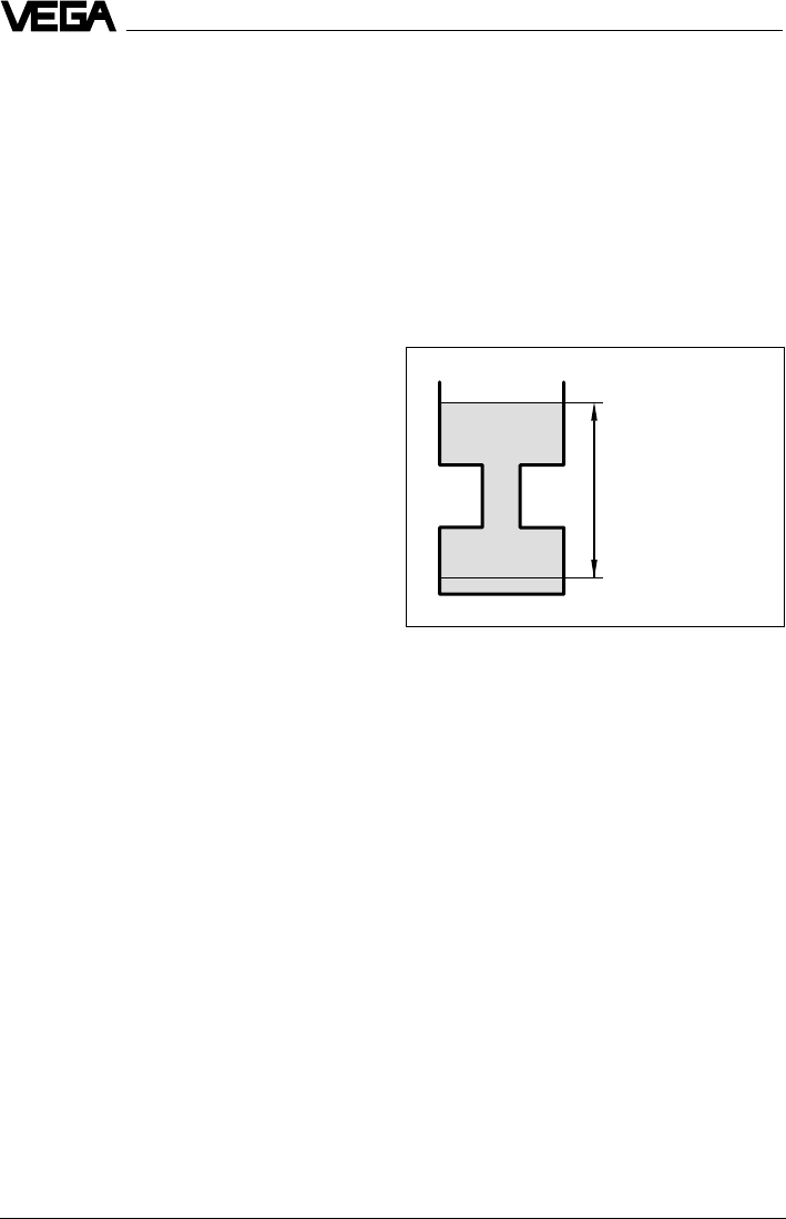
76 VEGAPULS 42 and 44 –4 … 20 mA
2. Operating range
Without special adjustment, the operating
range corresponds to the measuring range.
Generally, it is useful to choose a slightly
wider range (approx. 5 %) for the operating
range than for the measuring range.
Example:
Min./max. adjustment: 1.270 … 5.850 m;
adjust operating range to approx. 1.000 …
6.000 m.
Max.
Min.
100 % (1.270 m) correspond
to 1200 liters
Span (4.58 m)
0 % (5.850 m) corresponds
to 45 liters
3. Adjustment
Under the menu item "
Adjustment
“ you inform
the sensor of the measuring range it should
use.
You can carry out the adjustment with or
without medium. Generally you will carry out
the adjustment without medium, as you can
then adjust without an actual filling/emptying
cycle.
Error codes:
E013 No valid measured value
- Sensor in the warm-up phase
- Loss of the useful echo
E017 Adjustment span too small
E036 Sensor program not operating
- Sensor must be reprogrammed
(service)
- Fault signal also appears during
programming
E040 Hardware failure, electronics
defective
Adjustment steps
On pages 80 and 81 you will find the com-
plete menu schematic of the adjustment mod-
ule MINICOM.
Set up the sensor in the numbered se-
quence:
1. Measuring tube adjustments (only for
measurement in a standpipe)
2. Operating range
3. Adjustment
4. Conditioning
5. Meas. conditions
6. False echo storage (only required when
errors occur during operation).
7. Indication of the useful and noise level
8. Outputs
Short explanations to the setup steps 1 … 8
follow.
1. Measurement in a standpipe
Adjustment is only necessary, if the sensor is
mounted in a standpipe (surge or bypass
tube). When measuring in a standpipe, do a
sounding of the distance and correct the
display of measured value (which can differ
several percent from the sounded value)
according to the sounding. From then on, the
sensor corrects running time shift of the ra-
dar signal and displays the correct value of
the level in the standpipe (measuring tube).
Setup
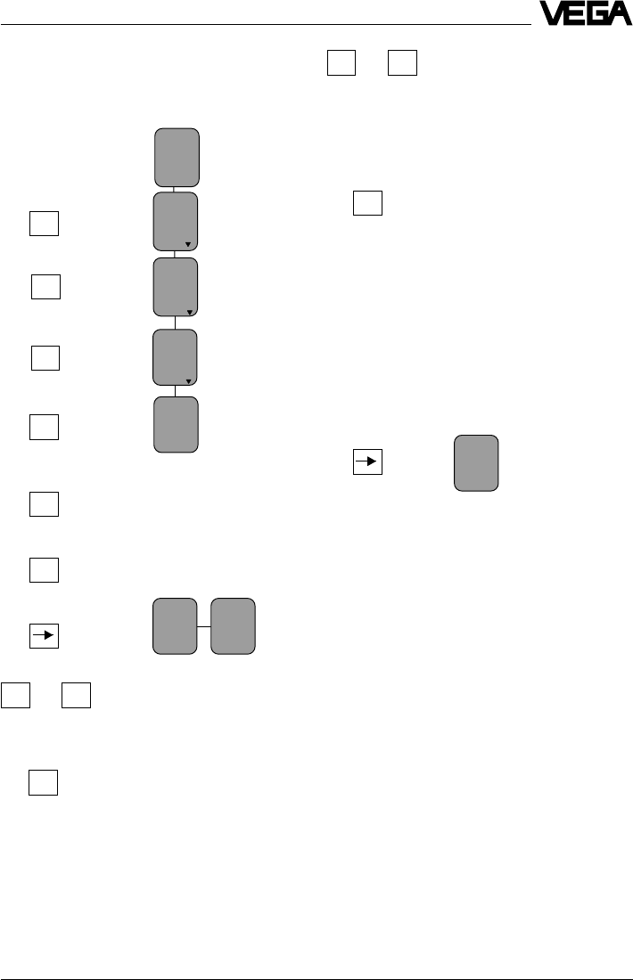
VEGAPULS 42 and 44 –4 … 20 mA 77
With the "
+
“ or "
–
“ key you can
assign a level distance (exam-
ple 5.85 m) to the previously
adjusted percentage value. If
you do not know the distance,
you have to do a sounding.
The adjusted product dis-
tance is written in the sensor
and the display stops flash-
ing.
You thereby adjusted the lower product dis-
tance as well as the percentage filling value
corresponding to the lower product distance.
Note:
For level detection outside the operating range,
the operating range must be corrected accord-
ingly in the menu "
Sensor optimisation/Opera-
ting range
“.
OK
+–
or
100.0%
at
m (d)
XX.XXX
(max. adjustment)
Now you make the max. adjustment (upper
product distance) (example: 100 % and
1.270 m product distance). First enter the per-
centage value and then the product distance
corresponding to the percentage value.
Note:
The difference between the adjustment val-
ues of the lower product distance and the
upper product distance should be as big as
possible, preferably at 0 % and 100 %. If the
values are very close together, e.g. lower
product distance indication at 40 % (3.102 m)
and upper product distance adjustment at
45 % (3.331 m), the measurement will be
inaccurate. A characteristic curve is gener-
ated from the two points. Even the smallest
deviations between actual product distance
and entered product distance will consider-
ably influence the slope of the characteristic
curve. If the adjustment points are too close
together, small errors inflate to considerably
larger ones when the 0 % or the 100 % value
is outputted.
Adjustment without medium
(adjustment independent of the level)
Key Display indication
Setup
Adjust-
ment
Para-
meter
Sensor
m(d)
4.700
w.o
medium
Adjust-
ment
in
m(d)
(min. adjustment)
OK
OK
+
OK
OK
OK
Adjust-
ment
in
m(d)
0.0%
at
m (d)
XX.XXX
OK
+–
or
The distance indication flashes
and you can choose "feet“ and
"m“.
Confirm the adjustment with
"
OK
“.
With "
+
“ and "
–
“ you adjust the
percentage value for the min.
value (example 0.0 %).
The adjusted percentage
value is written in the sensor
and the distance of the min.
value corresponding to the
percentage value flashes.
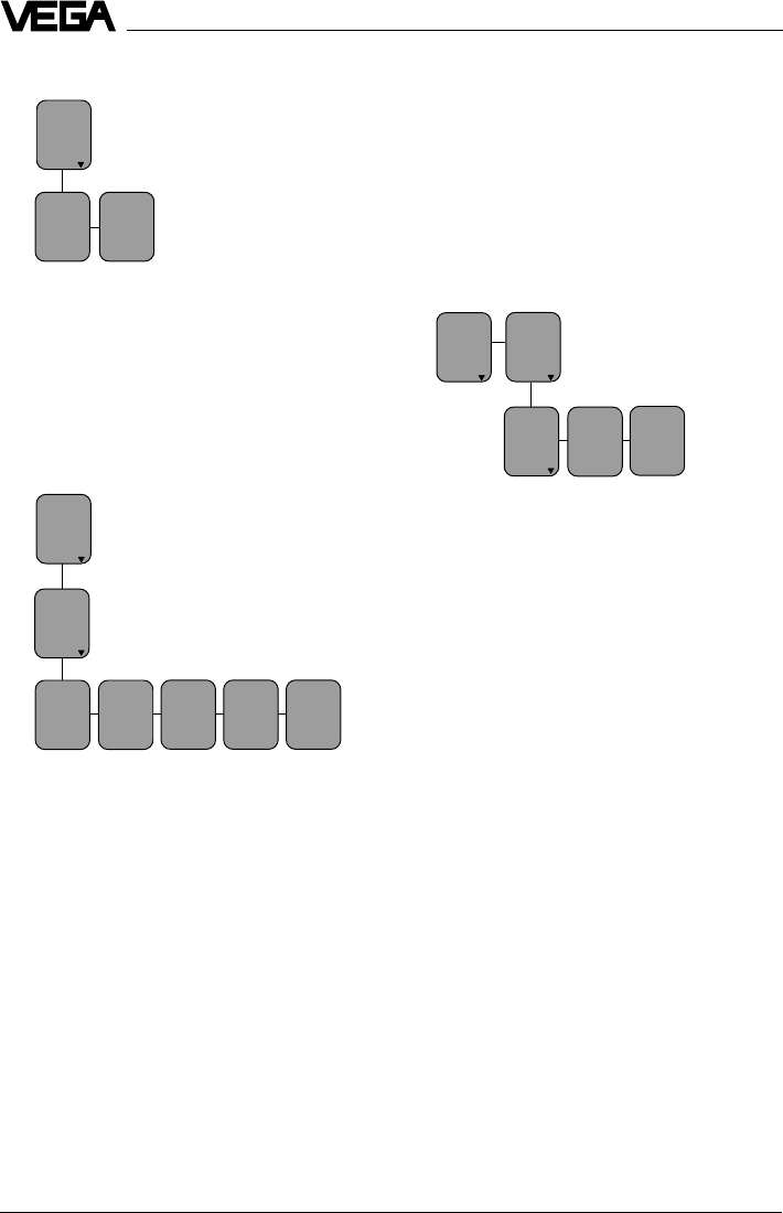
78 VEGAPULS 42 and 44 –4 … 20 mA
•Confirm with "
OK
“.
If necessary, choose a decimal point. How-
ever, note that only max. 4 digits can be
displayed. In the menu "
prop. to
“ you choose
the physical quantity (mass, volume, dis-
tance…) and in the menu "
Unit
“ the physical
unit (kg, l, ft3, gal, m3 …).
Linearisation:
Lin.
curve
Linear
Integr
ation
time 0 s
Adjust
ment Signal
condit
ioning
Scal
ing
A linear correlation between the percentage
value of the product distance and percent-
age value of the filling volume is preadjusted.
With the menu "Lin. curve“ you can choose
between linear, spherical tank and cylindrical
tank. The generation of a customized lineari-
sation curve is only possible with the PC and
the adjustment program VVO.
5. Meas. conditions
(see menu plan no. 5)
Choose „Liquid“ or „Solid“ and select the
options corresponding to your application.
6. False echo storage
A false echo storage is always useful when
unavoidable false echo sources (e.g. struts)
must be minimised. By creating a false echo
storage, you authorise the sensor electronics
to record the false echoes and save them in
an internal database. The sensor electronics
treats these (false) echoes differently from
the useful echoes and filters them out.
Setup
with
medium
Min.
adjust
at %
XXX.X
Max.
adjust
at %
XXX.X
Signal
condit
ioning
Scal
ing
0 %
corres
ponds
XXXX
100 %
corres
ponds
XXXX
Deci-
mal
point
888.8
prop.
to
Mass
Unit
Kg
Adjustment with medium
Fill the vessel e.g. to 10 % and enter 10 % in
the menu "
Min. adjust
“ with the "
+
“ and "
–
“
keys. Then fill the vessel, e.g. to 80 % or
100 % and enter 100 % in the menu "
Max.
adjust
“ with the "
+
“ and "
–
“ keys.
4. Conditioning
Under the menu item "
Conditioning
“ you as-
sign a product distance at 0 % and at 100 %
filling. Then you enter the parameter and the
physical unit as well as the decimal point.
Enter in the menu window "
0 % corresponds
“
the numerical value of the 0 % filling. In the
example of the adjustment with the PC and
the adjustment software VVO this would be
45 for 45 liters.
•Confirm with "
OK
“.
With the "—>“ key you change to the 100 %
menu. Enter here the numerical value of your
parameter corresponding to a 100 % filling.
In the example 1200 for 1200 liters.

VEGAPULS 42 and 44 –4 … 20 mA 79
Setup
Ampl.:
XX dB
S-N:
XX
dB
7. Signal-Noise divergence
In the menu
you get important information on the signal
quality of the product echo. The higher the
"S-N“ value, the more reliable the measure-
ment (menu schematic MINICOM).
Ampl.: means amplitude of the level echo in
dB (useful level)
S-N: means Signal-Noise, i.e. the useful
level minus the level of the back-
ground noise
The bigger the "S-N“ value (difference be-
tween the amplitudes of the useful signal level
and the noise level), the better the measure-
ment:
> 50 dB Measurement excellent
40 … 50 dB Measurement very good
20 … 40 dB Measurement good
10 … 20 dB Measurement satisfactory
5 … 10 dB Measurement sufficient
< 5 dB Measurement poor
Example:
Ampl. = 68 dB
S-N = 53 dB
68 dB – 53 dB = 15 dB
This means that the noise level is only
68 dB – 53 dB = 15 dB.
A 15 dB noise level with a 53 dB higher signal
level would ensure a high degree of meas-
urement reliability.
8. Outputs
Under the menu "Outputs“ you determine, for
example, if the current output should be
inverted, or in which unit of measurement the
measured value should appear in the sensor
display.
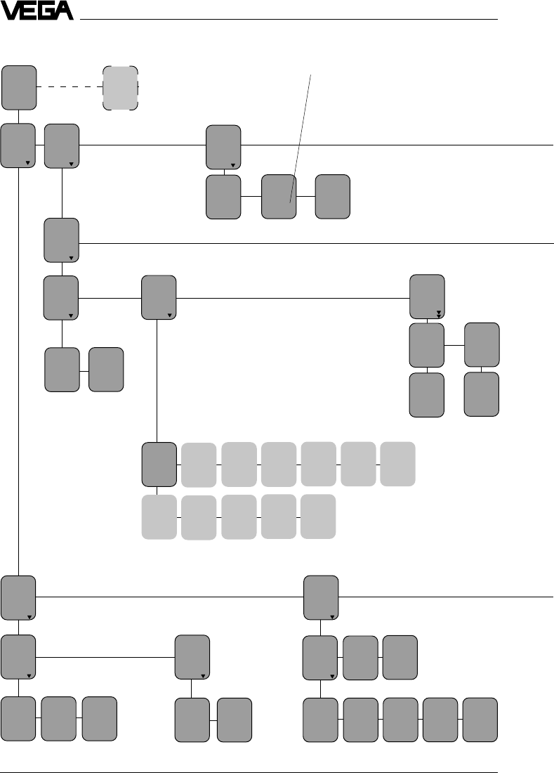
80 VEGAPULS 42 and 44 –4 … 20 mA
Setup
Menu schematic for the adjustment module MINICOM
Sensor
opti-
mize
Para-
meter
Sensor
m(d)
4.700
Meas.
enviro
nment
Opera-
ting
range
Begin
m (d)
0.50
End
m (d)
6.00
Meas.
condit
ions
Measur
ing in
tube
Correc
tion
Now!
OK?
Tube
diamet
mm (d)
50
PULS
44
K
2.00
When switching on, the sensor
type and the software version are
displayed for a few seconds.
2. 5. 1.
Correc
tion
Now!
OK?
Correc
tion
factor
2,50 %
Confi-
gura-
tion
Sensor
Tag
Sensor
Sensor
addr.
0
Meas.
unit
m (d)
Adjust
ment Signal
condit
ioning
w.out
medium
Adjust
ment
in
m(d)
with
medium
0.0 %
at
m (d)
XX.XXX
100.0%
at
m (d)
XX.XXX
Min-
adjust
at %
XXX.X
Max-
adjust
at %
XXX.X
Sca-
ling Lin.
curve
Linear
Integr
ation
time 0 s
0 %
corres
ponds
XXXX
100 %
corres
ponds
XXXX
Deci-
mal
point
888.8
Prop.
to
Mass
Unit
Kg
3. 4.
Condit
ion
liquid
Agitat
ed sur
face
No
Foam-
ing
prod.
No
Fast
change
No
Meas-
ure in
tube
No
Multi
ple
echo
No
Low DK
pro-
duct
No
Condit
ion
solid
High
dust
level
No
Large
angle
repose
No
Fast
change
No
Multi
ple
echo
No
Multidrop operation (HART® sensor
address):
•Sensor address zero: The sensor outputs
beside the 4…20 mA signal also a digital
(HART®) level signal.
•Sensor address 1…15: the sensor delivers
only a digital (HART®) level signal. The
sensor current is frozen to 4 mA (power
supply).
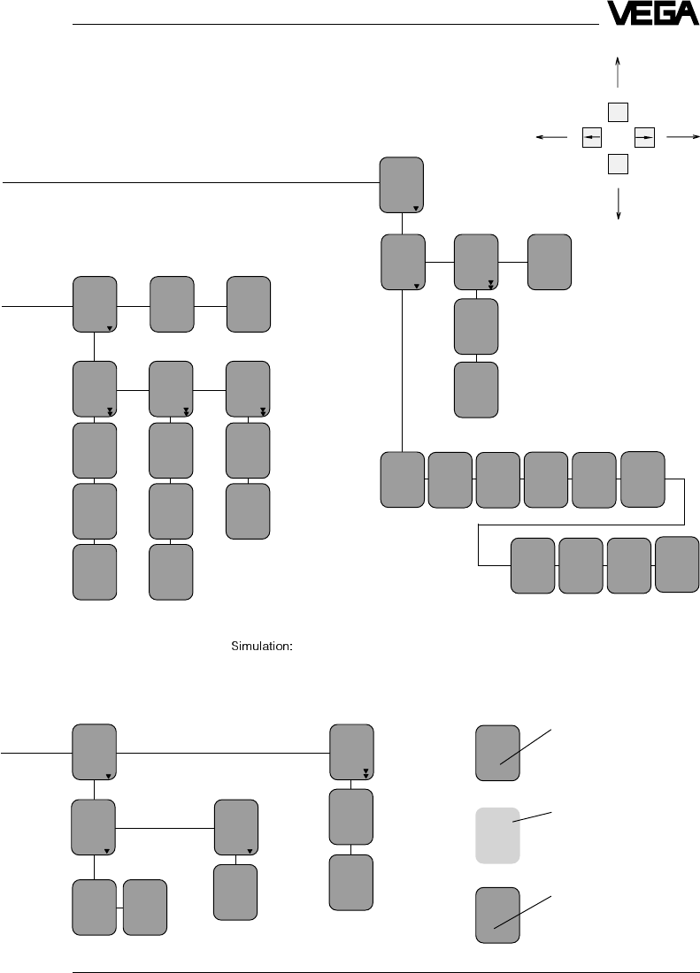
VEGAPULS 42 and 44 –4 … 20 mA 81
Setup
Create
new
Act.
dist.
m (d)
4.700
False
echo
memory
Update
Now!
OK?
Meas.
dist.
m (d)
X.XX
Learn-
ing!
Update
Update
Now!
OK?
Learn-
ing!
Delete
Delet-
ing!
Delete
Now!
OK?
Add’l
func-
tions
Info Lan-
guage
Eng-
lish
Reset
Now!
OK?
Reset
ing!
Basic
reset
Sensor
type
PULS54
K
Serial
number
1094
0213
Softw.
vers.
2.00
Act.
dist.
m (d)
4.700
max.
range
m (d)
7.000
Sensor
Tag
Sensor
Softw.
date
15.09.
1999
Meas.
dist.
m (d)
X.XX
Ampl.:
XX dB
S-N:
XX
dB
Ampl.:
XX dB
S-N:
XX
dB
With these keys you move in
the menu field to the left, right,
top and bottom
6. 7.
ESC
OK
One hour after the last simulation
adjustment the sensor returns
automatically to normal operating
mode.
Sensor
addr.
0
Foam-
ing
prod
Yes
Act.
dist.
m
X,XX
Light grey menu fields are only
displayed if required (dependent
on the adjustments in other
menus).
Menu items in bolt print provide
sensor and measured value
information and cannot be
modified in this position.
Fast
change
No
White menu items can be
modified with the "+“ or "–“ key
and saved with the "OK“ key.
Simu-
lation
Simu-
lation
Now!
OK?
Simu-
lation %
XXX.X
Out-
puts
Curr.
out-
put
Sensor
displ.
Fail-
ure
mode
22mA
Prop.
to
di-
stance
Curr-
out-
put
4-20mA
8.
Act.
current
mA
8.565
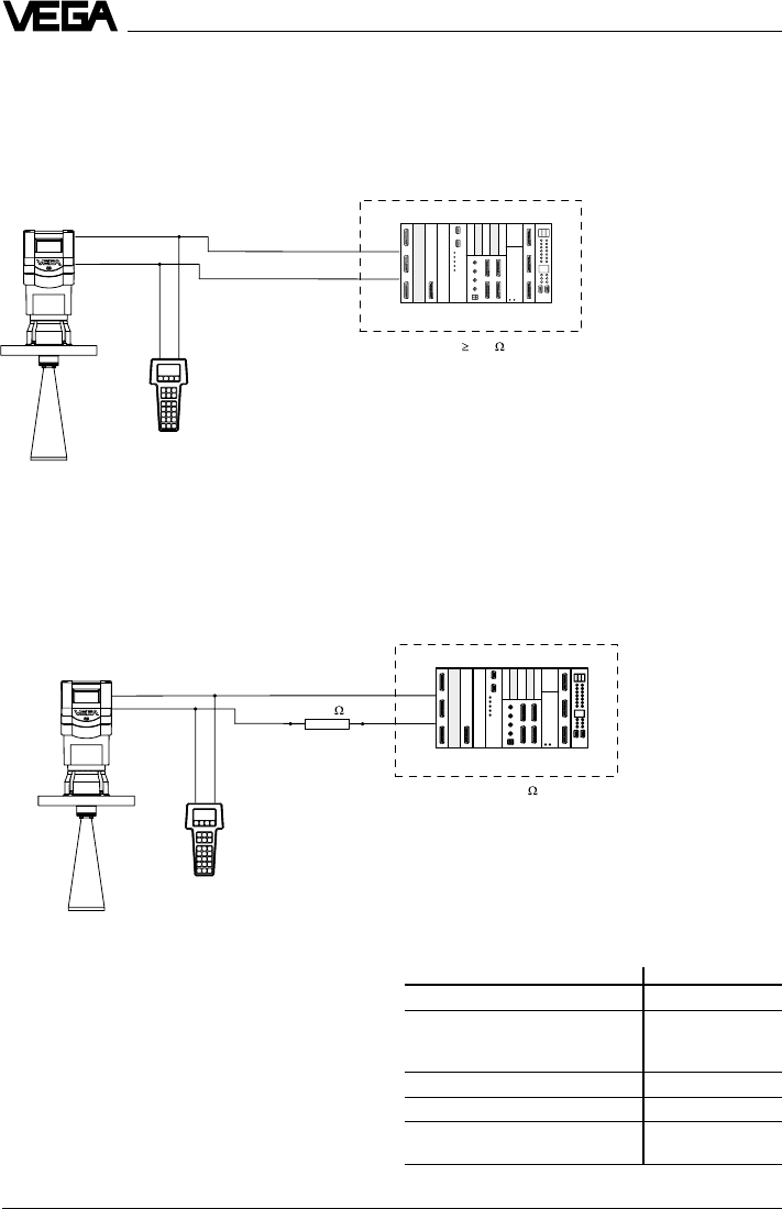
82 VEGAPULS 42 and 44 –4 … 20 mA
Connection to a VEGA signal conditioning
instrument
If you operate a HART® compatible sensor on
a VEGA signal conditioning instrument, you
have to connect the sensor via a resistor
(see following table) during HART® adjust-
ment in order to reach, together with the
internal resistance of the instruments, the
value of 250 Ohm required for the HART®
instrument. An inherent system load resist-
ance allows a corresponding reduction of Rx.
VEGA signal conditioning instr. Rx
VEGAMET 513, 514, 515, 602 50 … 100 Ohm
VEGAMET 614 no additional
VEGADIS 371 resistor
required
VEGAMET 601 200 … 250 Ohm
VEGASEL 643 150 … 200 Ohm
VEGAMET 513 S4, 514 S4
515 S4, VEGALOG EA card 100 … 150 Ohm
Setup
Just connect the HART® handheld to the
signal cable, after connecting the sensor to
power supply.
Note:
If the resistance of the power supply is less
than 250 Ohm, a resistor must be connected
into the signal/connection loop during adjust-
ment.
The digital adjustment and communication
signals would otherwise be short-circuited
due to insufficient resistance of the supply
current source or the processing system,
and as a result, communication with the sen-
sor would not be ensured.
+
-
Ri 250
250
+
-
Ri < 250
With any HART® handheld you can set up the
VEGAPULS 40K radar sensors like all other
HART® compatible sensors. A special DDD
(Data Device Description) is not necessary.
6.4 Adjustment with HART® handheld
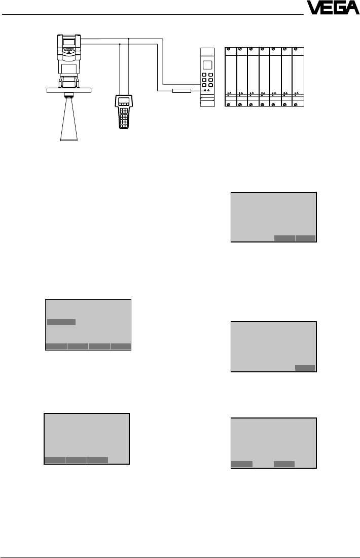
VEGAPULS 42 and 44 –4 … 20 mA 83
Setup
Rx
VEGAMET VEGALOG
The most important adjustment steps
On the following pages you see a menu
schematic for the HART® handheld in con-
junction with VEGAPULS 42 and 44 sensors.
The most important adjustment steps are
marked in the menu schematic with the letters
A … E. For parameter adjustment, first press
the key "
ENTER
“. The adjustment is thereby
saved in the handheld, but not in the sensor
itself.
After pressing "
SEND
“, a warning is dis-
played which informs you that you are about
to modify the configuration, and that for
safety reasons, you should switch your sys-
tem over to manual operation.
4.2
(5.2)
After having pressed "
ENTER
“, press "
SEND
“
(here in the example for the min. adjustment).
Press "
OK
“ and the adjustment will now be
transferred to the sensor. After a short time
you are asked to switch your system over
from manual to automatic operation. Confirm
with "
OK
“.
You see the adjustment that was just carried
out.
Generic: SENSOR
1 PV LRV 5.850 m
2 PV URV 1.270 m
HELP SEND HOME
Generic: SENSOR
PV URV
5.850 m
1.270 m
HELP DEL ESC ENTER
Generic: SENSOR
WARN-Loop should be
removed from
automatic control
ABORT OK
Generic: SENSOR
NOTE- Loop may be re-
turned to automatic control
OK
Generic: SENSOR
1 PV LRV 5.850 m
2 PV URV 1.270 m
HELP HOME
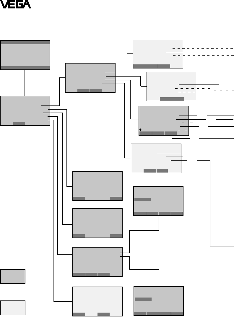
84 VEGAPULS 42 and 44 –4 … 20 mA
HART® menu schematic VEGAPULS 42 and 44
Setup
A
6 PV Dämpfung
1
2
3
4
5
1.1
1.2
1.3
1.4
4.1
(5.1)
4.2
(5.2)
1.4.3
1.3.1 1.3.2
not necessary
1.3.4
1.3.6
1.2.2
B
Switch on:
after approx.
20 s
(max.
meas.
distance)
(min.
meas.
distance)
Continue as under figure 4
linear
}
not necessary
}
Important and
necessary menu
windows
Less important
menu windows
Hart Communicator
Self Test
in Progress
Firmware Rev: F2.2
Module Rev: 3.6
01992-96 FRSI
Generic: SENSOR
Diag/Service
1 Test device
2 Loop test
3 Calibration
4 D/A trim
SAVE HOME
Generic: SENSOR
Detailed setup
1 Sensors
2 Signal condition
3 Output condition
4 Device information
SAVE HOME
Generic: SENSOR
Basic setup
1Tag
2 PV Unit
3 Range values
4 Device information
5 PV xfer fnctn
HELP SAVE HOME
Generic: SENSOR
Process variables
1 Snsr 2.281 m
2 AI % rnge 69,140 %
3 AO 1 15.059 mA
HELP SAVE HOME
Generic: SENSOR
Online(Generic)
1 Device setup
2 PV 2.281 m
3 PV AO 15.059 mA
4 PV LRV 20.000 m
5 PV URV 0.000 m
SAVE
Generic: SENSOR
Device setup
1 Process variables
2 Diag/Service
3 Basic setup
4 Detailed setup
5 Review
SAVE HOME
Generic: SENSOR
PV
2.281 m
HELP EXIT
Generic: SENSOR
AA1
15.264 mA
HELP EXIT
Generic: SENSOR
1 PV LRV 20.000 m
2 PV URV 0.000 m
HELP HOME
Generic: SENSOR
PV URV
0.000 m
0.300 m
HELP DEL ESC ENTER
Generic: SENSOR
PV LRV
20.000 m
5.850 m
HELP DEL ESC ENTER
Generic: SENSOR
1 PV LRV
20.000 m
2 PV URV 0.000 m
HELP HOME
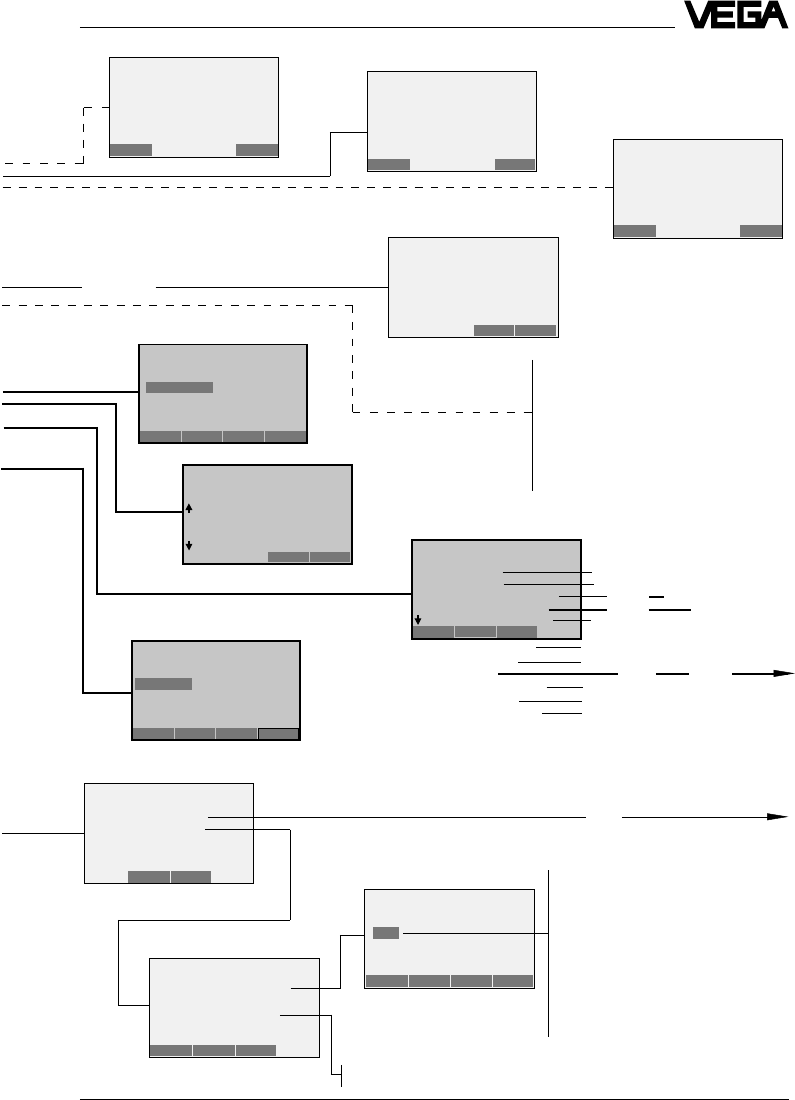
VEGAPULS 42 and 44 –4 … 20 mA 85
Setup
1.1.3
1.1.2
1.3.1
1.3.2
1.3.4
1.3.6 6 Write protect None
7 Descriptor
8 Message
9 PV Sensr s/n
Final asmbly num
Revision #’s
1.3.4.2
1.3.4.3
1.3.4.4
1.3.4.5
1.3.4.7 1.3.4.8
1.3.4.9
1.3.4.10
1.3.4.11
1.3.4.1
see next
page
1.3.4.6
C
1.2.2
Switch off
control Individual current values for test
purposes (measured value simula-
tion).
See also menu window 1.4.3.1.
on the next page
The following menu windows are not
supported by the sensor. Saving of adjust-
ments carried out here is not possible.
The adjustment of actual "empty“ or "full“
measured values should be carried out in
the menu window 4.1 and 4.2. Enter there
the meas. distance with empty vessel as
zero and the meas. distance with full
vessel as end.
Sensor serial number
E
1.4.3
1.4.3.2
OFF: Sensor signals measured values only on request
ON: Sensor signals measured values unrequested
1.4.3.2
D
like menu 1.3.1
see next
page
1.4.3.1
Multidrop operation (sensor address):
The sensor outputs beside the 4 … 20 mA
signal also a digital (HART®) level signal:
•Enquiry address zero, the sensor
consumes a level dependent 4 … 20 mA
current and delivers a digital (HART®)
level signal.
•Enquiry address 1 … 15, the sensor
delivers a digital (HART®) level signal
and the sensor current is frozen to 4 mA
(power supply).
The 4 … 20 mA signal is no longer
available.
Generic: SENSOR
PV
2.281 m
HELP EXIT Generic: SENSOR
A01
8.264 mA
HELP EXIT
Generic: SENSOR
PV % rnge
45.390 %
HELP EXIT
Generic: SENSOR
PV Damp
0.000 s
0.000 s
HELP DEL ESC ENTER
Generic: SENSOR
Device information
1 Distributor
2 Model
3 Dev id
4Tag
5 Date 01/01/97
HELP SAVE HOME
Generic: SENSOR
PV Snsr unit
mm
bbl
in
cm ESC ENTER
Generic: SENSOR
Tag
SENSOR
SENSOR
HELP DEL ESC ENTER
Generic: SENSOR
Choose analog output
level
1 4mA
2 20mA
3 Other
4 End ABORT ENTER
Generic: SENSOR
Output condition
1 Analog output
2 HART output
SAVE HOME
Generic: SENSOR
HART output
1 Poll addr 0
2 Num req preams 0
3 Burst mode
4 Burst option
HELP SAVE HOME
Generic: SENSOR
Poll addr
0
0
HELP DEL ESC ENTER
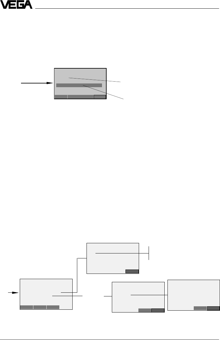
86 VEGAPULS 42 and 44 –4 … 20 mA
Setup
Continuation HART® menu schematic VEGAPULS 42 and 44
1.3.4.8
available initialisation words:
..SOL Meas. conditions solid
..LIQ Meas. condition liquid
..FED Delete false echo storage
..FEN04.58M False echo, e.g. at 4.58 m create new
..FEN48.67FT False echo, e.g. at 48.67 ft create new
..FEU03.68M Extend false echo storage:
add a new false echo to the false echo storage at 3.68 m
..FEU36.05FT add a new false echo to the false echo storage at 36.05 ft
initialisation word
(last entered)
Newly entered initialisation
word to be enquired with
ENTER and SEND
D
Note:
After entering the initialisation word, press "ENTER“ and then
"SEND“.
Confirm the message to change over to manual operation with
"OK“ and the message to switch over to automatic operation again
with "OK“.
Only then is the adjustment written into the sensor and made
active.
1.4.3.1
1.4.3.1.2
Low: In case of failure current output
goes to 22 mA
High: In case of failure current output
goes to < 3.6 mA
1.4.3.1.3 1.4.3.1.3.1
Warning:
Switch off
control!
False echo storage
Normally this menu is only
required for process vessels and
difficult installation conditions
of 1.3.4
of
1.4.3.
Generic: SENSOR
Message
..SOL
..FEN04.58M
HELP DEL ESC ENTER
Generic: SENSOR
Analog output
1 A01 13,467mA
2 A0 Alrm typ
3 Loop test
4 D/A trim
5 Scaled D/A trim
HELP SAVE HOME
Generic: SENSOR
Choose analog output
level
14 mA
2 20 mA
3 Other
4 End Abort Enter
Generic: SENSOR
Fld dev output is
fixed at 4.000 mA
ABORT OK
Generic: SENSOR
A0 Alrm typ
Hold last out valu
Exit

VEGAPULS 42 and 44 –4 … 20 mA 87
Diagnostics
7 Diagnostics
7.1 Simulation
For simulation of a certain filling, you can call
up the function “Simulation” in the adjustment
module MINICOM, in the software program
VVO or in the HART® handheld.
You simulate a vessel filling level and thereby
a certain sensor current. Please note that
connected instruments, such as e.g. a PLC
react according to their adjustments and will
probably activate alarms or system func-
tions. One hour after the last simulation ad-
justment, the sensor returns automatically to
standard operating mode.
7.2 Error codes
Error codes Rectification
E013 No valid measured value Message is displayed during warm-up phase
- Sensor in the warm-up phase
- Loss of the useful echo If the message remains, a false echo storage
must be made with the adjustment module
MINICOM in the menu “sensor optimisation” or
better, with the PC and VVO.
If the message still remains, carry out a new
adjustment.
E017 Adjustment span too small Carry out a readjustment.
Make sure that the difference between
min. and max. adjustment is at least 10 mm.
E036 Sensor software does not run Sensor must be programmed with new software
(service).
Message appears during a software update.
E040 Hardware failure/Electronics defec- Check all connection cables.
tive Contact our service department.

ISO 9001
The statements on types, application, use and operating conditions of
the sensors and processing systems correspond to the latest infor-
mation at the time of printing.
Technical data subject to alterations
2.24 897 / May 2000
VEGA Grieshaber KG
Am Hohenstein 113
D-77761 Schiltach
Phone (0 78 36) 50 - 0
Fax (0 78 36) 50 - 201
e-mail info@vega-g.de
internet www.vega-g.de