VEGA Grieshaber KG PMT8X External radio communication unit for level sensors and point level detection sensors User Manual Manual
VEGA Grieshaber KG External radio communication unit for level sensors and point level detection sensors Manual
Manual

Operating Instructions
External radio unit for HART sensors
PLICSMOBILE T81/B81/S81
External GSM/GPRS/UMTS radio unit
Optionally with battery/accumulator/solar
panel
Document ID: 55234

2
Contents
PLICSMOBILE T81/B81/S81 • External GSM/GPRS/UMTS radio unit
55234-EN-170206
Contents
1 About this document
1.1 Function ........................................................................................................................... 4
1.2 Target group ..................................................................................................................... 4
1.3 Symbols used................................................................................................................... 4
2 For your safety
2.1 Authorised personnel ....................................................................................................... 5
2.2 Appropriate use ................................................................................................................ 5
2.3 Warning about incorrect use ............................................................................................. 5
2.4 General safety instructions ............................................................................................... 5
2.5 Safety label on the instrument .......................................................................................... 5
2.6 EU conformity ................................................................................................................... 6
2.7 Radio license for Europe .................................................................................................. 6
2.8 Radio license for USA ...................................................................................................... 6
2.9 Radio license for Canada ................................................................................................. 7
2.10 Environmental instructions ............................................................................................... 7
3 Product description
3.1 Conguration .................................................................................................................... 8
3.2 Principle of operation........................................................................................................ 9
3.3 Adjustment ....................................................................................................................... 9
3.4 Packaging, transport and storage ..................................................................................... 9
4 Mounting
4.1 General instructions ....................................................................................................... 11
4.2 Installation procedure ..................................................................................................... 11
5 Connecting to power supply
5.1 Preparing the connection ............................................................................................... 14
5.2 Connection options ........................................................................................................ 14
5.3 Connection steps sensor connection cable .................................................................... 15
5.4 Connection steps voltage supply .................................................................................... 15
5.5 Wiring plan ..................................................................................................................... 17
6 Battery operation and power saving mode
6.1 Battery/accumulator operation ....................................................................................... 19
6.2 External battery PLICSMOBILE B81 .............................................................................. 19
6.3 Solar panel PLICSMOBILE S81 ..................................................................................... 20
6.4 Battery sizing.................................................................................................................. 22
6.5 Power options ................................................................................................................. 23
7 Setup
7.1 Adjustment system ......................................................................................................... 25
7.2 Communication via Bluetooth......................................................................................... 25
7.3 Parameter adjustment with PC and PACTware ............................................................... 26
7.4 Mobile network and SIM card ......................................................................................... 27
7.5 Internet connection and measured value transmission ................................................... 29
8 Maintenanceandfaultrectication
8.1 Maintenance .................................................................................................................. 32
8.2 Rectify faults ................................................................................................................... 32
8.3 How to proceed if a repair is necessary .......................................................................... 33

3
Contents
PLICSMOBILE T81/B81/S81 • External GSM/GPRS/UMTS radio unit
55234-EN-170206
9 Dismount
9.1 Dismounting steps.......................................................................................................... 34
9.2 Disposal ......................................................................................................................... 34
10 Supplement
10.1 Technical data ................................................................................................................ 35
10.2 Dimensions .................................................................................................................... 39
10.3 Industrial property rights ................................................................................................. 41
10.4 Hash function acc. to mbed TLS ..................................................................................... 41
10.5 Trademark ...................................................................................................................... 41
Supplementary documentation
Information:
Supplementary documents appropriate to the ordered version come
withthedelivery.Youcanndthemlistedinchapter"Product descrip-
tion".
Editing status: 2017-01-31
4
1 About this document
PLICSMOBILE T81/B81/S81 • External GSM/GPRS/UMTS radio unit
55234-EN-170206
1 About this document
1.1 Function
This operating instructions manual provides all the information you
need for mounting, connection and setup as well as important instruc-
tionsformaintenanceandfaultrectication.Pleasereadthisinforma-
tion before putting the instrument into operation and keep this manual
accessible in the immediate vicinity of the device.
1.2 Target group
This operating instructions manual is directed to trained specialist
personnel. The contents of this manual should be made available to
these personnel and put into practice by them.
1.3 Symbols used
Information, tip, note
This symbol indicates helpful additional information.
Caution: If this warning is ignored, faults or malfunctions can result.
Warning: If this warning is ignored, injury to persons and/or serious
damage to the instrument can result.
Danger: If this warning is ignored, serious injury to persons and/or
destruction of the instrument can result.
Ex applications
This symbol indicates special instructions for Ex applications.
SIL applications
This symbol indicates instructions for functional safety which must be
taken into account particularly for safety-relevant applications.
• List
The dot set in front indicates a list with no implied sequence.
→ Action
This arrow indicates a single action.
1 Sequence of actions
Numbers set in front indicate successive steps in a procedure.
Battery disposal
This symbol indicates special information about the disposal of bat-
teries and accumulators.

5
2 For your safety
PLICSMOBILE T81/B81/S81 • External GSM/GPRS/UMTS radio unit
55234-EN-170206
2 For your safety
2.1 Authorised personnel
All operations described in this operating instructions manual must
be carried out only by trained specialist personnel authorised by the
plant operator.
During work on and with the device the required personal protective
equipment must always be worn.
2.2 Appropriate use
The PLICSMOBILE T81 is an external mobile network unit for trans-
mission of measured values and for remote parameter adjustment of
plics® sensors.
Operational reliability is ensured only if the instrument is properly
usedaccordingtothespecicationsintheoperatinginstructions
manual as well as possible supplementary instructions.
For safety and warranty reasons, any invasive work on the device
beyond that described in the operating instructions manual may be
carried out only by personnel authorised by the manufacturer. Arbi-
traryconversionsormodicationsareexplicitlyforbidden.
2.3 Warning about incorrect use
Inappropriate or incorrect use of the instrument can give rise to
application-specichazards,e.g.vesseloverllordamagetosystem
components through incorrect mounting or adjustment.
2.4 General safety instructions
This is a state-of-the-art instrument complying with all prevailing
regulations and guidelines. The instrument must only be operated in a
technicallyawlessandreliablecondition.Theoperatorisresponsible
for the trouble-free operation of the instrument.
During the entire duration of use, the user is obliged to determine the
compliance of the necessary occupational safety measures with the
current valid rules and regulations and also take note of new regula-
tions.
The safety instructions in this operating instructions manual, the na-
tional installation standards as well as the valid safety regulations and
accident prevention rules must be observed by the user.
For safety and warranty reasons, any invasive work on the device
beyond that described in the operating instructions manual may be
carried out only by personnel authorised by the manufacturer. Arbi-
traryconversionsormodicationsareexplicitlyforbidden.
The safety approval markings and safety tips on the device must also
be observed.
2.5 Safety label on the instrument
The safety approval markings and safety tips on the device must be
observed.

6
2 For your safety
PLICSMOBILE T81/B81/S81 • External GSM/GPRS/UMTS radio unit
55234-EN-170206
2.6 EU conformity
ThedevicefullsthelegalrequirementsoftheapplicableEUguide-
lines.ByaxingtheCEmarking,weconrmsuccessfultestingofthe
product.
YoucanndtheEUconformitydeclarationonourwebsiteunder
www.vega.com/downloads.
2.7 Radio license for Europe
The instrument was tested according to the latest issues of the har-
monized standards:
• EN 300328
• EN 301511
• EN 301908-1
• EN 301908-2
• EN 300440
It is hence approved for use inside closed vessels in countries of the
EU and EFTA.
2.8 Radio license for USA
This approval is only valid for USA. Hence the following text is only
available in the English language:
This device complies with Part 15 of the FCC Rules. Operation is
subject to the following two conditions:
• This device may not cause interference, and
• This device must accept any interference, including interference
that may cause undesired operation of the device
Changesormodicationsnotexpresslyapprovedbythemanufac-
turer could void the user’s authority to operate this equipment.
This device is approved for unrestricted use only inside closed, sta-
tionaryvesselsmadeofmetal,reinforcedberglassorconcrete.
This equipment complies with FCC radiation exposure limits set forth
for an uncontrolled environment. This equipment should be installed
and operated with minimum distance of 20 cm cm between the radia-
tor and your body. This transmitter must not be co-located or operat-
ing in conjunction with any other antenna or transmitter.
This equipment has been tested and found to comply with the limits
for a Class B digital device, pursuant to Part 15 of the FCC Rules.
These limits are designed to provide reasonable protection against
harmful interference in a residential installation. This equipment
generates, uses and can radiate radio frequency energy and, if not
installed and used in accordance with the instructions, may cause
harmful interference to radio communications. However, there is no
guarantee that interference will not occur in a particular installation. If
this equipment does cause harmful interference to radio or television
reception,whichcanbedeterminedbyturningtheequipmentoand
on, the user is encouraged to try to correct the interference by one or
more of the following measures:
• Reorient or relocate the receiving antenna

7
2 For your safety
PLICSMOBILE T81/B81/S81 • External GSM/GPRS/UMTS radio unit
55234-EN-170206
• Increase the separation between the equipment and receiver
• Connecttheequipmentintoanoutletonacircuitdierentfrom
that to which the receiver is connected
• Consult the dealer or an experienced radio/TV technician for help
2.9 Radio license for Canada
This approval is only valid for Canada. Hence the following texts are
only available in the English/French language:
This device complies with Industry Canada's license-exempt RSS
standard(s). Operation is subject to the following conditions:
• This device may not cause interference, and
• This device must accept any interference, including interference
that may cause undesired operation of the device
This equipment complies with IC radiation exposure limits set forth for
an uncontrolled environment. This equipment should be installed and
operated with minimum distance of 20 cm cm between the radiator
and your body. This transmitter must not be co-located or operating in
conjunction with any other antenna or transmitter.
Le présent appareil est conforme aux CNR d’Industrie Canada ap-
plicables aux appareils radio exempts de licence. L’exploitation est
autorisée aux conditions suivantes:
• L’appareil ne doit pas produire de brouillage; et
• L’utilisateur de l’appareil doit accepter tout brouillage radioélect-
rique subi, même si le brouillage est susceptible d’en compromet-
tre le fonctionnement.
Cet équipement est conforme aux limites d'exposition aux rayonne-
ments IC établies pour un environnement non contrôlé. Cet équipe-
ment doit être installé et utilisé avec un minimum de 20 cm cm de
distance entre la source de rayonnement et votre corps. Ce transmet-
teur ne doit pas être place au même endroit ou utilise simultanément
avec un autre transmetteur ou antenne.
2.10 Environmental instructions
Protection of the environment is one of our most important duties.
That is why we have introduced an environment management system
with the goal of continuously improving company environmental pro-
tection.Theenvironmentmanagementsystemiscertiedaccording
to DIN EN ISO 14001.
Pleasehelpusfullthisobligationbyobservingtheenvironmental
instructions in this manual:
• Chapter"Packaging, transport and storage"
• Chapter"Disposal"
8
3 Product description
PLICSMOBILE T81/B81/S81 • External GSM/GPRS/UMTS radio unit
55234-EN-170206
3 Product description
3.1 Conguration
The scope of delivery encompasses:
• PLICSMOBILE T81
• Sensor connection cable (optional)
• Documentation
– This operating instructions manual
– Ifnecessary,furthercerticates
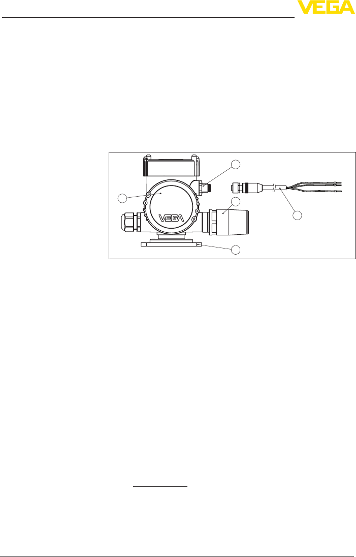
The PLICSMOBILE T81 consists of the components:
2
5
3
4
1
Fig. 1: PLICSMOBILE T81
1 Electronics compartment
2 Plug connector for connection of the sensor
3 Antenna
4 Mounting plate
5 Sensor connection cable
Thetypelabelcontainsthemostimportantdataforidenticationand
use of the instrument:
• Instrument type
• Product code
• Approvals
• Technical data
• Serial number of the instrument
• Data matrix code for smartphone app
The type label contains the serial number of the instrument. With it
youcanndthefollowingdataonourhomepage:
• Product code of the instrument (HTML)
• Delivery date (HTML)
• Order-specicinstrumentfeatures(HTML)
• Operating instructions at the time of shipment (PDF)
Goto"www.vega.com","VEGA Tools"and"Instrument search".Enter
the serial number.
Alternatively, you can access the data via your smartphone:
• Downloadthesmartphoneapp"VEGA Tools"fromthe"Apple App
Store"orthe"Google Play Store"
• Scan the Data Matrix code on the type label of the instrument or
Scope of delivery
Constituent parts
Type label
Serial number

9
3 Product description
PLICSMOBILE T81/B81/S81 • External GSM/GPRS/UMTS radio unit
55234-EN-170206
• Enter the serial number manually in the app
3.2 Principle of operation
The PLICSMOBILE T81 is a mobile network unit for transmission
of measured values and for remote parameter adjustment of plics®
sensors. Due to the large operating voltage range and the integrated
power saving functions, a mains-independent power supply via bat-
tery or accumulator/solar cells is possible. Typical applications are
measured value transmission from mobile vessels, battery-operated
level measurement and deep well measurement.
The measured value and message transmission can be optionally
carried out via e-mail or SMS. Furthermore, the measured values can
betransmittedviahttpsforvisualisationin"VEGA Inventory System".
The use of PLICSMOBILE T81 is particularly suitable for inventory
management, VMI (Vendor Managed Inventory) and remote enquiry.
The external mobile network unit PLICSMOBILE T81 can be con-
nected to any 4 … 20 mA HART two-wire sensor of the plics® series.
In HART Multidrop operation up to 15 sensors can be connected to a
PLICSMOBILET81(max.vewithExversion).
The transmission of measured values, event messages and diagnos-
tic information to the user is carried out via the GSM/GPRS network.
Thanks to quadband technology, the device can be used virtually
anywhere in the world. There is also the option of accessing the con-
nected sensor via remote parameter adjustment.
Power is supplied via a standard low voltage source (external power
supply unit/battery/accumulator/solar panel) or via the optionally
availablePLICSMOBILEB81.Youcannddetailedspecicationson
thepowersupplyinchapter"Technical data".
The PLICSMOBILE T81 normally supplies power to the connected
sensors.
3.3 Adjustment
The device is adjusted via PACTware and the corresponding DTM.
The connection is made via the Bluetooth module integrated in
PLICSMOBILE T81.
3.4 Packaging, transport and storage
Your instrument was protected by packaging during transport. Its
capacity to handle normal loads during transport is assured by a test
based on ISO 4180.
The packaging of standard instruments consists of environment-
friendly, recyclable cardboard. For special versions, PE foam or PE
foil is also used. Dispose of the packaging material via specialised
recycling companies.
Transport must be carried out in due consideration of the notes on the
transport packaging. Nonobservance of these instructions can cause
damage to the device.
Application area
Functional principle
Voltage supply
Packaging
Transport

10
3 Product description
PLICSMOBILE T81/B81/S81 • External GSM/GPRS/UMTS radio unit
55234-EN-170206
The delivery must be checked for completeness and possible transit
damage immediately at receipt. Ascertained transit damage or con-
cealed defects must be appropriately dealt with.
Up to the time of installation, the packages must be left closed and
stored according to the orientation and storage markings on the
outside.
Unless otherwise indicated, the packages must be stored only under
the following conditions:
• Not in the open
• Dry and dust free
• Not exposed to corrosive media
• Protected against solar radiation
• Avoiding mechanical shock and vibration
• Storageandtransporttemperatureseechapter"Supplement -
Technical data - Ambient conditions"
• Relative humidity 20 … 85 %
Transport inspection
Storage
Storage and transport
temperature

11
4 Mounting
PLICSMOBILE T81/B81/S81 • External GSM/GPRS/UMTS radio unit
55234-EN-170206
4 Mounting
4.1 General instructions
In the standard version, the PLICSMOBILE T81 is designed for
wall mounting. Mounting adapters for carrier rail mounting (top hat
rail 35 x 7.5 according to DIN EN 50022/60715) as well as for tube
mounting are optionally available.
Checkbeforemountingifasucientnetworkcoverage(signal
strength) of the mobile network provider is available at the planned
location. This can be simply tested by means of a mobile phone.
Keep in mind that the SIM cards in the PLICSMOBILE T81 and in the
mobile phone are from the same mobile phone provider or work in the
same mobile phone network. If the radio reception is too weak, you
should search for a better position. In closed rooms this would be, for
example, close to a window or at least closer to an outer wall.
Note:
During operation, a distance of at least 20 cm should be kept between
the antenna and persons working nearby. Operation of the instrument
with smaller distances is not recommended.
Usetherecommendedcables(seechapter"Connecting to power
supply")andtightenthecablegland.
You can give your instrument additional protection against moisture
penetration by leading the connection cable downward in front of the
cableentry.Rainandcondensationwatercanthusdraino.Thisap-
plies mainly to outdoor mounting as well as installation in areas where
high humidity is expected (e.g. through cleaning processes) or on
cooled or heated vessels.
4.2 Installation procedure
The PLICSMOBILE T81 for wall mounting is supplied with a mounting
base for screw mounting.
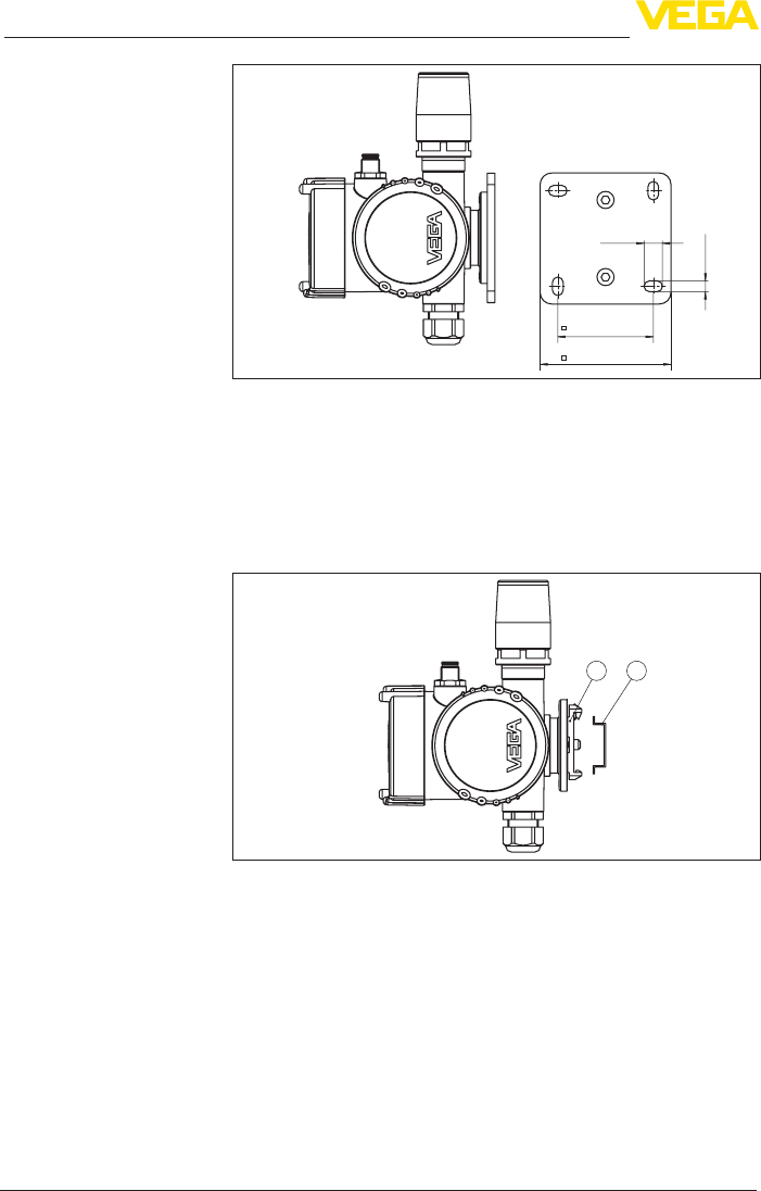
→ Fasten the instrument with four appropriate screws (not included
in the delivery) according to the following illustration.
Mounting options
Installation position
Moisture
Wall mounting
12
4 Mounting
PLICSMOBILE T81/B81/S81 • External GSM/GPRS/UMTS radio unit
55234-EN-170206
62 mm (2.44")
12 mm
(0.47")
7 mm
(0.28")
85 mm (3.35")
Fig. 2: PLICSMOBILE T81 for wall mounting, bottom view of mounting plate.
The PLICSMOBILE T81 for top hat rail mounting is supplied with an
already assembled adapter for fastening on a 35 x 7.5 carrier rail.
→ Snap the instrument without tools onto the top hat rail. Loosening
from the top hat rail is also carried out without tools. Through the
integrated spring, you just have to apply slight lateral pressure to
the instrument.
1 2
Fig. 3: PLICSMOBILE T81 for carrier rail mounting
1 Adapter plate
2 Carrier rail
The PLICSMOBILE T81 for tube mounting is supplied with a measur-
ing instrument holder and four hexagon socket screws M5 x 12 as
unassembled mounting accessory.
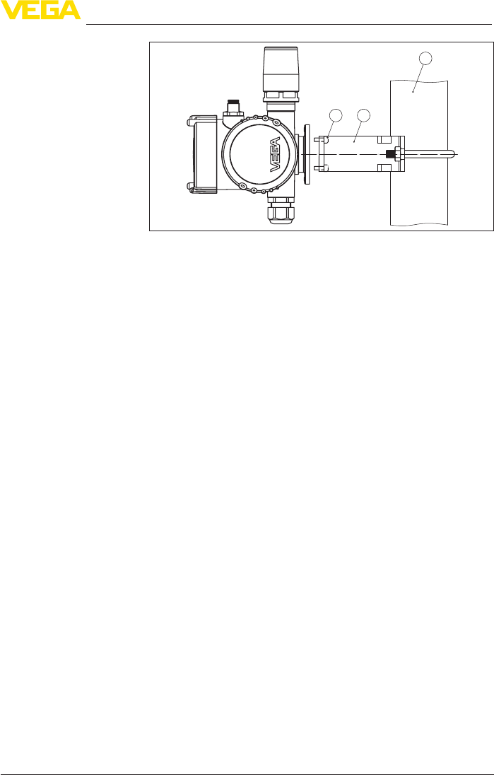
→ Mount the measuring instrument holder according to the following
illustration to the socket of PLICSMOBILE T81. Then you can
fasten the instrument with the bent strap to your tube.
Carrier rail mounting
Tube mounting
13
4 Mounting
PLICSMOBILE T81/B81/S81 • External GSM/GPRS/UMTS radio unit
55234-EN-170206
1 2
3
Fig. 4: PLICSMOBILE T81 for tube mounting
1 4 screws M5 x 12
2 Measuring instrument holder
3 Tube

14
5 Connecting to power supply
PLICSMOBILE T81/B81/S81 • External GSM/GPRS/UMTS radio unit
55234-EN-170206
5 Connecting to power supply
5.1 Preparing the connection
Always keep in mind the following safety instructions:
• Connect only in the complete absence of line voltage
• If overvoltage surges are expected, overvoltage arresters should
be installed
Power can be supplied optionally via PLICSMOBILE B81 or a sepa-
rate power supply unit.
When using a power supply unit, the secondary circuit must be
separated from the primary circuit by double or reinforced insulation
(according to the nationally valid safety standards).
The air and creeping distances in PLICSMOBILE T81 meet the
requirements of EN IEC61010-1 for secondary circuits with reinforced
insulation under overvoltage category III (altitude up to 2000 m).
The voltage supply of PLICSMOBILE T81 is connected with standard
cable according to the national installation standards.
The sensor connection cable included in the delivery is used to con-
nect the sensor.
Connect the cable screen on the sensor side to ground potential.
In the sensor, the screen must be connected directly to the internal
ground terminal. The ground terminal on the outside of the sensor
housing must be connected to the potential equalisation (low imped-
ance).
Note:
WhenconnectingmorethanoneHARTsensor,adierentaddress
must be assigned to each sensor (address range 1-15). Address 0
(mode 4 … 20 mA) may not be used. When assigning an address,
only one sensor should be connected to PLICSMOBILE T81. If con-
nectionisalreadycompleted,thewiringmustbebrieyundonefor
addressing. Depending on the installation location of the sensors, it
can be advantageous to carry out this addressing before installing
and connecting the sensors. This can be conveniently carried out
e.g. in the workshop. You only need a 24 Volt power supply as well as
an indicating and adjustment module PLICSCOM or the adjustment
software PACTware with VEGACONNECT.
5.2 Connection options
Power can be supplied to the sensor and PLICSMOBILE in two ways:
With this version, only one voltage supply is required for both devices.
The voltage supply is connected to the PLICSMOBILE T81. In
addition to the measured value, the sensor connection cable also
carries the voltage supply of the sensor via HART. Hence there is
no 4 … 20 mA HART signal from the sensor electronics available for
processing, e.g. via a PLC. That's why the measured value transmis-
Note safety instructions
Select power supply
Select connection cable
Cable screening and
grounding
Common voltage sup-
ply for sensor and
PLICSMOBILE

15
5 Connecting to power supply
PLICSMOBILE T81/B81/S81 • External GSM/GPRS/UMTS radio unit
55234-EN-170206
sion can only be carried out via radio transmission through e-mail/
SMS/VEGA Inventory System.
With this version, the sensor and the PLICSMOBILE T81 are each
powered via a separate power supply. Here, the measured values can
be transmitted via radio communication and the 4 … 20 mA HART
signal is available in parallel for processing, e.g. via a PLC.
HART communication
If the internal resistance of the connected power supply for the sensor
islessthan230Ω,theHARTsignalisextremelydampedorshort-
circuited. Digital communication with PLICSCOM is then no longer
possible. With low impedance processing systems, a resistance of
approx.230Ωmustbeloopedintothe4…20mAcable.Thisresist-
ance is already integrated in PLICSMOBILE T81 and can be looped
automatically into the circuit by selecting the appropriate wires (see
wiring plan).
The connection to power supply is carried out as described in the
respective operating instructions manual.
5.3 Connection steps sensor connection cable
The sensor connection cable is used for transmission of the meas-
ured value from the sensor to the PLICSMOBILE T81. In addition, it
can also transmit the voltage supply for the connected sensor.
The sensor connection cable is available in Ex version (blue)
as well as in non-Ex version (black). It can be ordered in three
lengths (5/10/25 m) and can be shortened afterwards to individual
lengths. On one end there is a ready-for-use plug for connection to
PLICSMOBILE T81. On the other end are free cable ends for direct
connection to the sensor.
To connect, proceed as follows:
1. Connect the colour coded wire ends to the respective sensor
terminals, as described in the wiring plan and the operating
instructions of the sensor.
2. Isolate unused wires, depending on connection type and cable
version
3. Connect the screen to the internal ground terminal, connect the
outer ground terminal on the housing to potential equalisation
4. Tighten the compression nut of the cable entry gland. The seal
ring must completely encircle the cable
5. Insert the plug of the sensor connection cable into the plug con-
nection on PLICSMOBILE T81
6. Tighten plug connection
5.4 Connection steps voltage supply
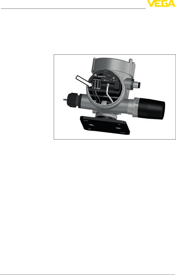
The connection of the voltage supply is made via spring-loaded termi-
nals in the electronics compartment. A small screwdriver is required
toopentheterminals.Solidaswellasexiblecoreswithoutcableend
sleeves can be used.
Separate voltage sup-
ply for sensor and
PLICSMOBILE
Connection technology
16
5 Connecting to power supply
PLICSMOBILE T81/B81/S81 • External GSM/GPRS/UMTS radio unit
55234-EN-170206
Proceed as follows:
1. Unscrew the housing lid
2. Loosen compression nut of the cable gland and remove blind
plug
3. Remove approx. 10 cm (4 in) of the cable mantle, strip approx.
1 cm (0.4 in) of insulation from the ends of the individual wires
4. Insert the cable into the cable gland through the cable entry
Fig. 5: Connection steps 4 and 5
5. Lift the opening levers of the terminals with a screwdriver
6. Insert the wire ends into the open terminals according to the wir-
ing plan
7. Press down the opening levers of the terminals, you will hear the
terminal spring closing
8. Check the hold of the wires in the terminals by lightly pulling on
them
9. Connect the screen to the internal ground terminal, connect the
external ground terminal to potential equalisation
10. Tighten the compression nut of the cable entry gland. The seal
ring must completely encircle the cable
11. Screw the housing lid back on
Theelectricalconnectionisnished.
Connection procedure
17
5 Connecting to power supply
PLICSMOBILE T81/B81/S81 • External GSM/GPRS/UMTS radio unit
55234-EN-170206
5.5 Wiring plan
1
PLICSMOBILE
4 5
2
6
3
5
12
+
-
678
4...20mA
SIM
Status
Send Off On
123
+-
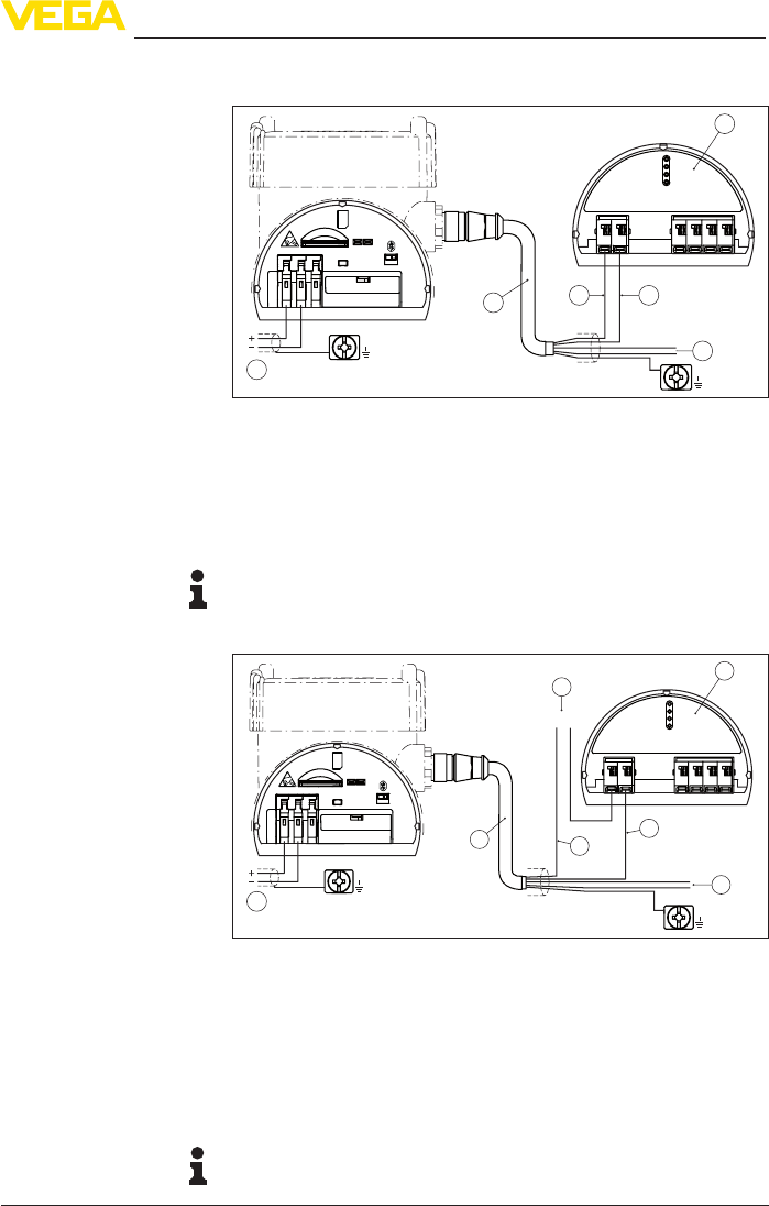
Fig. 6: Connection of the voltage supply in the electronics housing
1 Power supply PLICSMOBILE and sensor
2 Sensor connection cable
3 HART sensor from the plics® series
4 Brown cable (+) for sensor power supply/HART communication
5 Blue cable (-) for sensor power supply/HART communication
6 Unused wires that must be insulated (not present on Ex version)
Note:
If multiple sensors are connected, they are connected in parallel. The
sensorsshouldrstbesettoHARTMultidropmode
1
PLICSMOBILE
45
2
7
63
5
12
+
+
-
-
678
4...20mA
SIM
Status
Send Off On
123
+
-
Fig. 7: Connection of the voltage supply in the electronics housing
1 Power supply PLICSMOBILE
2 Sensor connection cable
3 HART sensor from the plics® series
4 Brown cable (+) for HART communication
5 Blue cable (-) with HART resistance, as an alternative white cable (-) without
HART resistance
6 Voltage supply, sensor
7 Unused cores to be insulated
Note:
The unused cores of the sensor connection cable must be insulated.
Wiring plan with voltage
supply of the sensor via
PLICSMOBILE
Wiring plan with external
voltage supply of the
sensor
18
5 Connecting to power supply
PLICSMOBILE T81/B81/S81 • External GSM/GPRS/UMTS radio unit
55234-EN-170206
SIM
Status
Send Off On
123
+-
123
+
-
45
+
-
+
-
Output
Solar panel
input
Output
OffOn
PLICSMOBILE T81
PLICSMOBILE B81
3
2
1
54
6
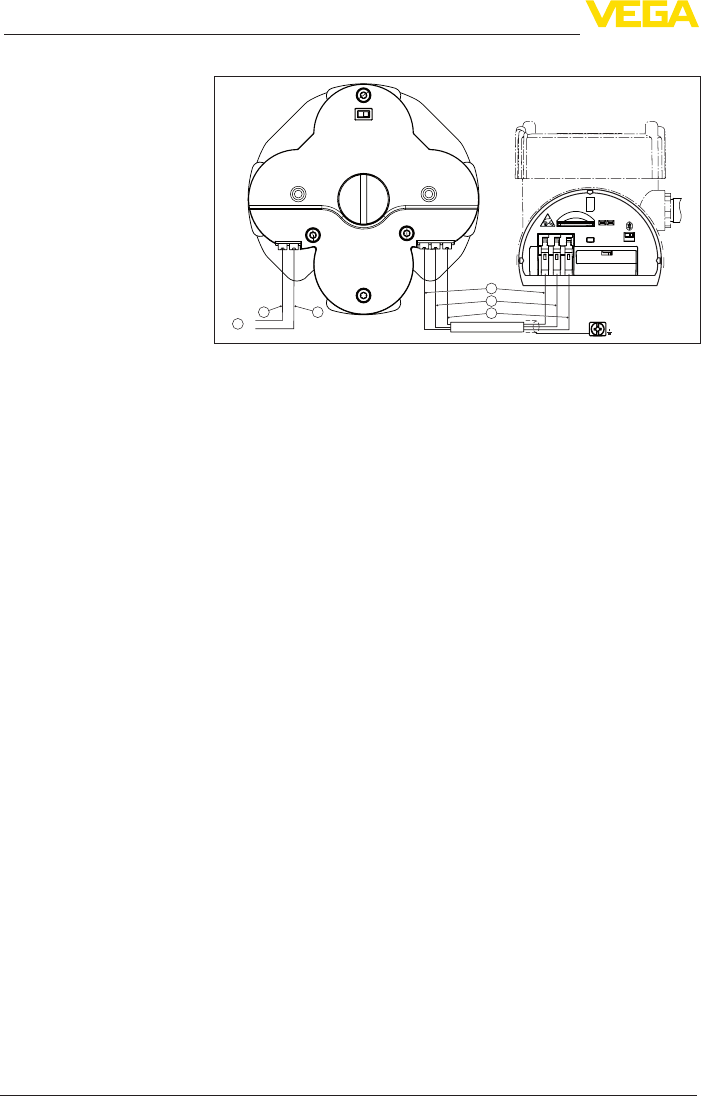
Fig. 8: Connection of the battery and the solar panel
1 Brown cable (+) for sensor power supply
2 Blue cable (-) for sensor power supply
3 White cable for communication PLICSMOBILE T81 - B81
4 Brown cable (+) for accumulator charging via solar panel
5 Blue cable (-) for accumulator charging via solar panel
6 Power supply from the solar panel
Wiring plan battery/solar
panel

19
6 Battery operation and power saving mode
PLICSMOBILE T81/B81/S81 • External GSM/GPRS/UMTS radio unit
55234-EN-170206
6 Battery operation and power saving mode
6.1 Battery/accumulator operation
If no mains voltage is available, PLICSMOBILE can be also powered
with batteries. For this purpose, an optional power pack is available
in a separate housing (PLICSMOBILE B81). This power pack can be
either ordered or equipped with chargeable accumulators or Lithium
batteries. As an alternative, an external battery/accumulator can be
connectedviathevoltagesupplyterminals.Youcannddetailed
informationofthevoltagesupplyinchapter"Technical data".
When battery/accumulator operation and time-controlled measure-
ment transmission are activated, the power saving mode should be
switchedonandtheBluetoothfunctionswitchedotoincreasethe
operatingtime(detailsseechapter"Power options").Inaddition,the
HART Multidrop mode should be switched on.
Note:
For charging the accumulators the ambient temperature must be in
a range of 0 … +45 °C (+32 … +113 °F). Temperatures outside this
range are permitted, however due to the protective circuit integrated
in the instrument, charging is not possible.
6.2 External battery PLICSMOBILE B81
The PLICSMOBILE B81 was especially developed for the power
supply of PLICSMOBILE T81. It can be optionally equipped with
rechargeable accumulators or non-rechargeable batteries of series
"D"(Mono).
Note:
ThereisasafetyinstructionleaetattachedtoeachPLICSMOBILE
B81 which must be read before setup and observed.
With the Ex version, one of the two following batteries/accumulators
must be used. If other batteries/accumulators are used, the approval
becomes invalid.
If there is no solar panel available at the installation location, then
PLICSMOBILE B81 should be equipped with non-chargeable Li-
batteries. As an alternative, standard Alkaline batteries can be used,
the lifetime is hence shorter. We recommend using Lithium batter-
iesLSH20ofMessrs.Saft(VEGAorderno.2.54970).Youcannd
further information of this battery type in the technical data.
Warning:
Whenusingnon-chargeablebatteries,theterminalsofthe"Solar
Panel Input"mustnotbeconnected.Ifvoltageisapplied,thebatteries
willbedestroyedandtherewillbearehazard.
If a solar panel is used, PLICSMOBILE B81 must be equipped with
rechargeable NiMH accumulators. The solar panel is connected di-
rectly to terminals 4 and 5, a charge regulator is integrated in the bat-
tery cover. We recommend the use of NiMH accumulators 5030641
Battery operation
Accumulator operation

20
6 Battery operation and power saving mode
PLICSMOBILE T81/B81/S81 • External GSM/GPRS/UMTS radio unit
55234-EN-170206
fromAnsmann(VEGAorderingno.2.54971).Youcanndfurther
information about this battery type in the technical data.
Note:
For charging the accumulators the temperature must be in a range
of 0 … +45 °C (+32 … +113 °F). Temperatures outside this range
are permitted, however due to the protective circuit integrated in the
instrument, charging is not possible.
The battery cable joins PLICSMOBILE B81 with PLICSMOBILE T81.
It is available with 5/10/25 m length. Connect the cable as shown in
the wiring plan. Make sure that the terminals of both instruments are
connected 1 : 1 via this cable.
1. Make sure that the switch on the upper side of the cover is set to
"OFF"
2. Unscrewthecentralxingscrewwithacoin.Thenyoucanre-
move the battery cover.
3. Insert the four batteries/accumulators into the battery compart-
ment. The respective polarity is printed at the bottom of the
compartment but also in the battery cover.
4. Place back the battery cover to the battery compartment. Make
sure that the position is correct, the battery cover can only be at-
tached in one direction.
5. Push the battery cover slightly downward on the points marked
with"PUSH"andscrewinthecentralxingscrew.
6. If all components are connected completely, you can set the
switchontheuppersideofthebatterycoverto"ON"
6.3 Solar panel PLICSMOBILE S81
Via the solar panel PLICSMOBILE S81 you can power the
PLICSMOBILE T81, the accumulator pack will also be charged. Two
solarpanelswithdierentsize/capacityareavailable:withasunny
environment and max. one measured value transmission per day, the
small5Wmoduleissucient;withintermittentshadowingand/or
more than one measured value transmission per day, the larger 20 W
module should be used. The technical data of both modules and the
order information can be found in the supplement of this instruction
manual.
Orient the solar module in such a way that in sunless seasons its
positionisidealtothesunandmaximumeciencyisachieved.Be-
cause in these seasons, the sun is very low, a steep installation angle
(approx. 60 - 75 degrees) is recommended so that the sunrays reach
the module at right angles. A tube holder suitable for the module is
available in the scope of delivery. The adjustment range of the inclina-
tion is 38 to 75 degrees, the orientation of the direction is individually
possible due to the tube mounted. As an option also a holder for
mounting on vertical surfaces such as walls is available.
Connection
Insert batteries
Mounting
21
6 Battery operation and power saving mode
PLICSMOBILE T81/B81/S81 • External GSM/GPRS/UMTS radio unit
55234-EN-170206
Note:
The tube holder of the solar module is suitable for tube diameters of
30 … 60 mm (1.2 … 1.4 in). If the PLCSMOBILE should be mounted
to the same tube, a tube with ø 60 mm is required.
Fasten the PLICSMOBILE close to the solar module to avoid unnec-
essary voltage loss on the cable.
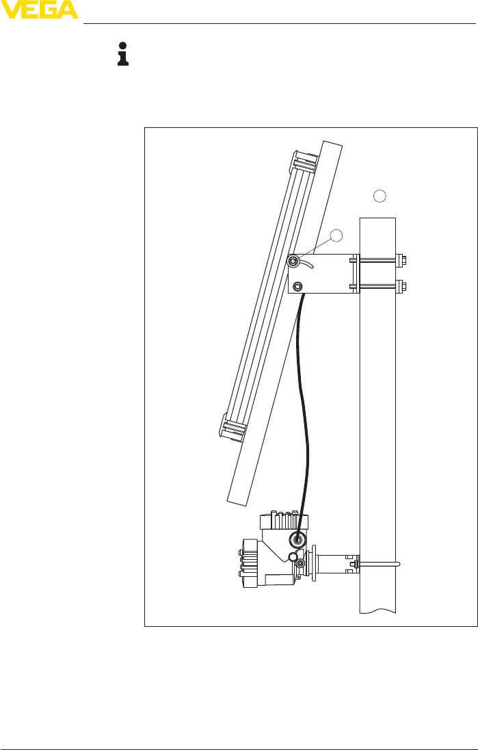
1
2
Fig. 9: Tube mounting PLICSMOBILE with solar module
1 Tube/mast with ø 60 mm (1.4 in)
2 Adjusting screw, inclination angle
The solar cable combines the power pack with the solar panel. It is
available in the lengths 5/10/25 m. Connect the cable as shown in the
wiring plan.
Connection

22
6 Battery operation and power saving mode
PLICSMOBILE T81/B81/S81 • External GSM/GPRS/UMTS radio unit
55234-EN-170206
Note:
Make sure that the two cores of the connection cable are energized
when the solar module is already connected and not covered. Avoid
a short circuit during mounting and connection. Also pay attention to
this when shortening the cable, if that should be necessary.
6.4 Battery sizing
When selecting an external battery/accumulator, the following points
must be observed:
Power consumption in power saving mode:
If you use a battery or accumulator that cannot be automatically
recharged cyclically, the power saving mode should be activated.
With an operating voltage of e.g. 12 V, a standby power consumption
of 0.4 mW must be taken into account. With an assumed lifetime of
e.g. one year, the requirement is approximately 3.5 Wh, which cor-
responds to a battery capacity of 0.29 Ah at 12 V. The standby power
consumptionatspecicoperatingvoltagesisstatedinthe"Technical
data".
Power requirement for a complete measurement cycle incl.
measured value transmission:
A measurement cycle lasts approximately 60 to 120 seconds (de-
pendent on sensor type and network quality) and includes automatic
switching on of the sensor (HART multidrop mode with 4 mA),
recording of the measured value, measured value transmission and
a return to the power saving mode. During this time, approximately
15 mWh of energy is required. For example, with one measurement
per day, this adds up to approx. 7.3 Wh per year, which corresponds
to a battery capacity of approx. 0.6 Ah at 12 V.
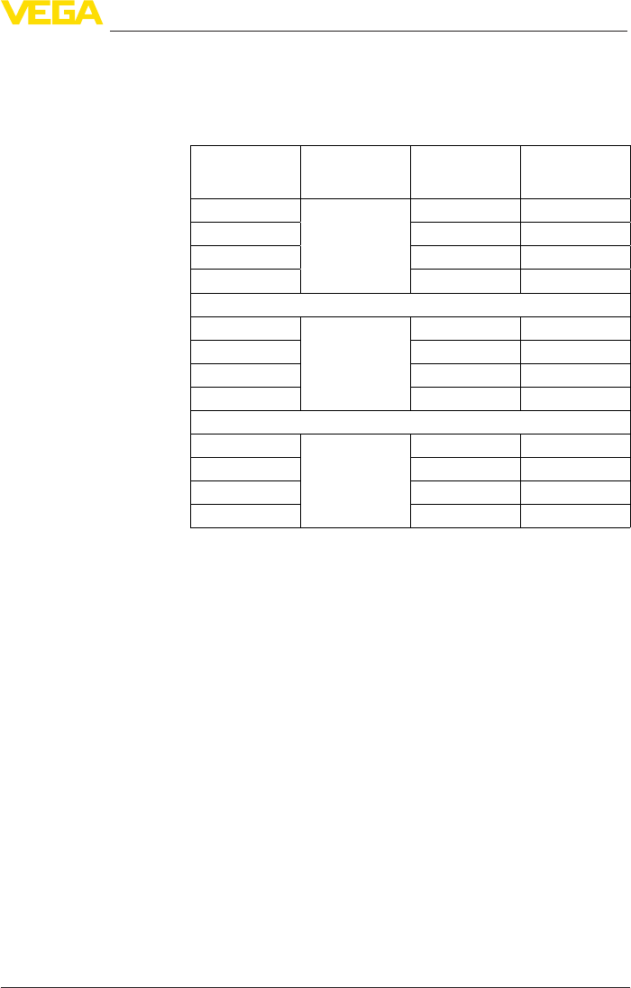
Examples for battery capacity depending on the number of
transmission cycles
Number of mes-
sages/day
Annual consumption PLICSMOBILE
Standby energy
demand
Energy demand
for message
transmission
Required battery
capacitance with
12 V
13.5 Wh 7.3 Wh 0.6 Ah
23.5 Wh 14.6 Wh 1.5 Ah
43.5 Wh 29.2 2.7 Ah
83.5 Wh 58.4 Wh 5.1 Ah
24 3.5 Wh 175.2 Wh 14.9 Ah
Note:
Due to the nature of the system, each battery and accumulator has a
self-discharge which can vary considerably dependent on the type.
This is very important for the calculation of the required capacitance.
In the listed examples, this self-discharge is not taken into accunt. The
available capacitance depends also considerably from the tempera-
ture.Thespecicationsrefertoatemperatureof20°C(68°F).
23
6 Battery operation and power saving mode
PLICSMOBILE T81/B81/S81 • External GSM/GPRS/UMTS radio unit
55234-EN-170206
Operating times with PLICSMOBILE B81
Inthefollowingtableyoucanndexemplarytheoperatingtimes
when using PLICSMOBILE B81, depending on the number of
sensors and messages per day as well as activated/deactivated
Bluetooth function.
Number of mes-
sages
Number of sen-
sors
Operating time
of the battery in
years
Operating time
of the accumula-
tor in years
1 1 >10/3.7* 3/0.7*
5 5.1/2.5* 0.9/0.5*
10 2.9/1.8* 0.3/0.3*
24 1.3/1.0* 0.2/0.2*
1 2 >10 2.8
5 4.6 0.9
10 2.6 0.5
24 1.1 0.2
1 5 >10 2.4
5 3.6 0.7
10 1.9 0.4
24 0.9 0.2
The values marked with * correspond to the operating time with acti-
vated Bluetooth module.
6.5 Power options
IntheDTM(seechapter"Parameter adjustment with PACTware")
youcanselectunderthemenuitem"Energy options"betweenthe
modes"Continuous operation"and"Power saving mode".
In continuous (non-stop) operation PLICSMOBILE and the sensor
always remain switched on. Only in this mode can the instrument be
used for level monitoring and send an e-mail when a certain level is
reached or when an error occurs (measured value/status-controlled
transmission). In continuous operation PLICSMOBILE allows remote
parameteradjustmentviatheservicedepartment.Conguration
changes on PLICSMOBILE as well as the sensor can thus be carried
out remotely from any PC with PACTware via GPRS.
In this mode, the integrated GSM modem as well as the sensor
connected to PLICSMOBILE are switched on automatically when
the time-controlled transmission of a message is pending. After the
measured value is recorded, the log-in into the GSM network is car-
ried out and the measured value is transmitted. The instrument then
returns to power saving mode. The time for this process depends on
the network quality and is generally approx. 70 seconds.
Permanent operation
Power saving mode

24
6 Battery operation and power saving mode
PLICSMOBILE T81/B81/S81 • External GSM/GPRS/UMTS radio unit
55234-EN-170206
Note:
Please note that event-controlled transmission (measured value/
status-controlled) is not possible in the power saving mode. A dial-in
connection for remote parameter adjustment is also not possible dur-
ing the inactive time.
When using battery operation and a HART sensor with non-required
4 … 20 mA signal, we recommend setting the sensor to multidrop
mode. In such case, the sensor consumes constantly only 4 mA
independently of the measured level, which increases the battery
life considerably. When connecting one or more sensors, the HART
multidrop mode is a basic requirement. A description of the activation
of multidrop mode can be found in the operating instructions of the
display and adjustment module.
With activated Bluetooth function, additional energy is needed; this
reduces the operating time with battery/accumulator operation con-
siderably.Forthatreason,switchotheBluetoothfunctionifitisnot
being used (via the switch on the electronics module).
HART multidrop
Bluetooth
25
7 Setup
PLICSMOBILE T81/B81/S81 • External GSM/GPRS/UMTS radio unit
55234-EN-170206
7 Setup
7.1 Adjustment system
Thedial-uptothecongurationofPLICSMOBILET81iscarriedout
via Bluetooth. For setup, a PC with PACTware and corresponding
DTM is required. You also need the VEGA Bluetooth USB adapter;
other Bluetooth modules, possibly already built into the PC or note-
book, or other USB adapters cannot be used. As an alternative, the
VEGA app for smartphones or tablets (iOS or Android) can be used.
In such case you can use the Bluetooth module already integrated in
the smartphone/tablet.
An activated SIM card (Mini-SIM) with data transmission option must
be used in PLICSMOBILE T81. The GSM/GPRS network must have
good coverage at the installation site.
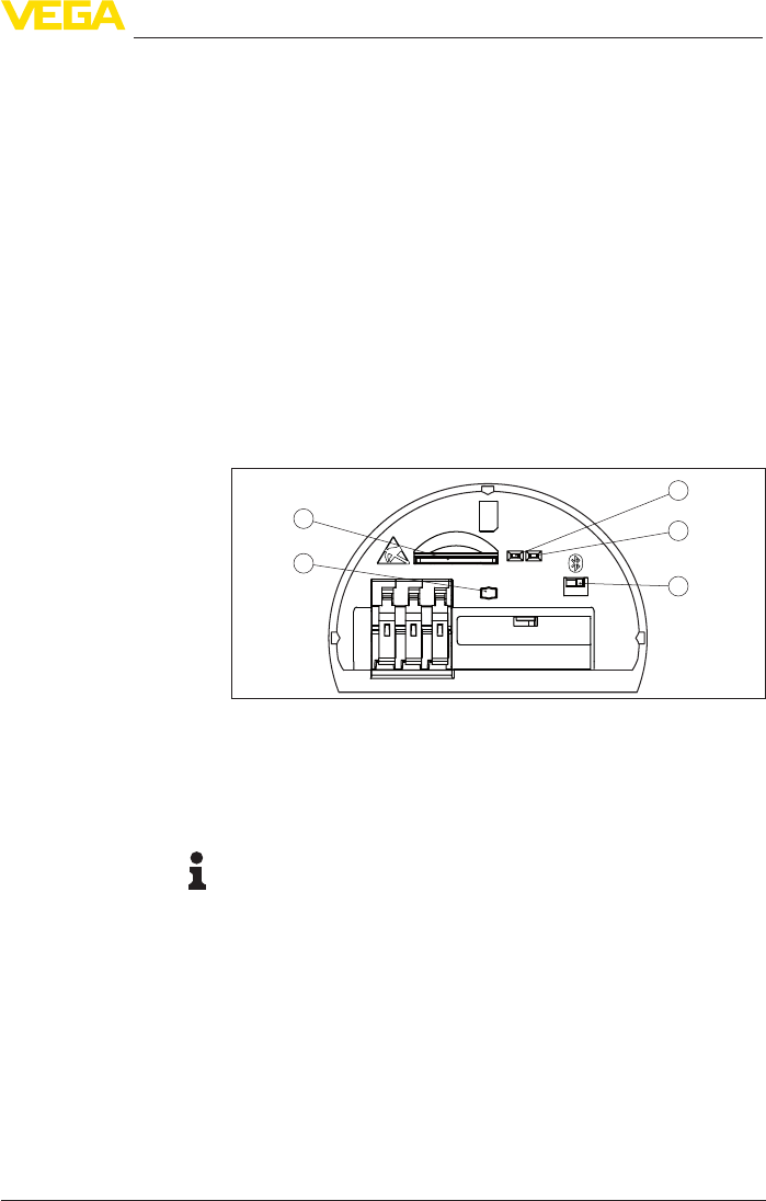
Control elements on the device itself are limited to a test key and two
LEDs. With these, operational readiness and the status of the instru-
ment can be checked (connection to GSM network, standby …).
5
24
3
1
SIM
Status
Send Off On
Fig. 10: Display and adjustment elements
1 Key for testing operational readiness
2 SIM card slot (Mini-SIM format)
3 Status indication, mobile network (yellow)
4 Status indication, Bluetooth (blue)
5 Bluetooth switch
Information:
The function description of the key and the status indication is avail-
ableinchapter"Mobile phone network and SIM card".
7.2 Communication via Bluetooth
The parameter adjustment of PLICSMOBILE T81 is only carried out
via the integrated Bluetooth interface. Thus a wireless connection to
dierentoperatingdevicesispossible.Thesecanbesmartphones/
tablets with iOS or Android operating system or PCs/notebooks with
Windows operating system and Bluetooth USB adapter.
There is a slide switch on the upper side of the electronics module for
activating/deactivating the Bluetooth function. With switch position
"On",connectioncanbeestablished.Aftertheparameteradjustment
Setup requirements
Display and adjustment
elements
Bluetooth switch

26
7 Setup
PLICSMOBILE T81/B81/S81 • External GSM/GPRS/UMTS radio unit
55234-EN-170206
itisgenerallyrecommendedtosettheswitchto"O".Lesspoweris
consumed this way and the lifetime of the battery is increased.
7.3 Parameter adjustment with PC and PACTware
For adjustment via Windows PC, a Bluetooth USB adapter and the
congurationsoftwarePACTwarewiththesuitableinstrumentdriver
(DTM) according to FDT standard are required. The up-to-date PACT-
ware version as well as all available DTMs are compiled in a DTM
Collection. The DTMs can also be integrated in other frame applica-
tions according to FDT standard.
Note:
To ensure that all instrument functions are supported, you should
always use the latest DTM Collection. Furthermore, not all described
functionsareincludedinolderrmwareversions.Youcandownload
the latest instrument software from our homepage. A description of
the update procedure is also available in the Internet.
The basic operation of the software is described in the operating
instructionsmanual"DTM Collection/PACTware"attachedtoeach
DTM Collection and which can also be downloaded from the Internet.
Detailed descriptions are available in the online help of PACTware and
the DTMs.
All device DTMs are available as a free-of-charge standard version
and as a full version that must be purchased. In the standard version,
all functions for complete setup are already included. An assistant for
simpleprojectcongurationsimpliestheadjustmentconsiderably.
Saving/printing the project as well as import/export functions are also
part of the standard version.
In the full version there is also an extended print function for complete
project documentation as well as a save function for measured value
and echo curves. In addition, there is a tank calculation program as
well as a multiviewer for display and analysis of the saved measured
value and echo curves.
The VEGA Bluetooth USB adapter is required for communication with
PLICSMOBILE T81. A Bluetooth module (possibly already installed
in the PC or notebook) or a USB adapter from another manufacturer
cannotbeused.Youcanndfurtherinformationintheinstructions
booklet of the Bluetooth USB adapter.
Make sure that the Bluetooth switch on the electronics module is set
to"On"andtheBluetoothUSBadapterisinserted.
Start the project assistant in PACTware; the Bluetooth USB adapter,
the PLICSMOBILE T81 and the connected sensors should then be
found and displayed in the project window.
The protection against unauthorized access to the PLICSMOBILE
T81issetupontwosteps.TherststepistheBluetoothaccess
protection, controlling the general access to the instrument. After this
step, reading out the parameters is always possible. Via the second
Prerequisites
Standard/Full version
Bluetooth USB adapter
Connecting via Bluetooth
Access protection

27
7 Setup
PLICSMOBILE T81/B81/S81 • External GSM/GPRS/UMTS radio unit
55234-EN-170206
step, the parameter protection, the change of the instrument settings
can be blocked.
With activated Bluetooth access, connection to the instrument is
only possible if the respective Bluetooth access code is known. This
numerical access code (6-digit) is stored in the instrument and can
bereadoutandmodiedviaDTM.Inaddition,thecodeislistedin
the accompanying documents available in the scope of delivery. With
activated Bluetooth access, the access code must be entered only
once per adjustment tool because it is automatically stored with the
rstconnectiontotheadjustmenttool.
Information:
As a default setting, access protection is deactivated. To prevent from
unauthorized change of the instrument data, the Bluetooth access
protection and the following parameter protection should be activated.
As an alternative, the Bluetooth function can be deactivated via the
switch in the instrument.
Withparameterprotectionactivated,themodicationofdevice
parameters is blocked. By entering a numerical device code (four to
ten digits), the device is temporarily unlocked for a parameter change.
After 60 minutes without any adjustments being made, the instrument
is locked again automatically. Parameter protection is deactivated by
default.
7.4 Mobile network and SIM card
An activated SIM card (Mini-SIM format) with data transmission op-
tion is required for setup.
Information:
The SIM card does not belong to the standard scope of delivery of
the device. To avoid roaming costs, the card should be bought in the
country in which the PLICSMOBILE T81 is installed and operated. If
you are using a VEGA Ident Card, you don't have to worry about this
because no roaming costs are charged.
To make the measured value transmission and remote maintenance
assimpleaspossible,VEGAoerstheservicepackage"Wireless
data transmission".ThispackageincludesanIdentCard(SIMcardin
Mini-SIM format) that covers all data transmission costs and provides
worldwide 24-hour support.
Incoming data connections (PLICSMOBILE) can only be established
if the SIM card used supports GPRS. Incoming data connections are
used for remote parameter adjustment via VEGA service.
Information:
When the power saving mode is activated in PLICSMOBILE, it cannot
be contacted for remote parameter adjustment during the inactive
time. During the active time (during a data transmission), incoming
connections are accepted and maintained independent of the power
saving mode until the connection is terminated.
Bluetooth access protec-
tion
Parameter protection
VEGA-Ident-Card
Remote parameter ad-
justment
28
7 Setup
PLICSMOBILE T81/B81/S81 • External GSM/GPRS/UMTS radio unit
55234-EN-170206
Data connections outgoing from PLICSMOBILE are established
via GPRS (volume-based billing). Outgoing connection are used
for measured value transmission via e-mail/SMS/VEGA Inventory
System.
During the transmission of the measured value via e-mail or Inventory
System, approximately 5 KB data are transmitted. With hourly trans-
mission, for example, this results in a monthly total net data volume of
approximately 4 MB.
The mobile network provider carries out a so-called block rounding
thatdependsontheselectedtari.WhencheckingoutoftheGPRS
network, the values are rounded to next higher billing units. Since
PLICSMOBILE checks out of the GPRS network after the transmis-
sion of every message (if the energy saving mode is activated),
this block rounding applies to each transmission. If, for example, a
tariwithblockroundingto100KBisused,anhourlymeasurement
transmission results in a monthly billing volume of over 70 MB. For
thatreason,youshouldchooseapuredatatariplan(M2M)withthe
lowest possible block rounding.
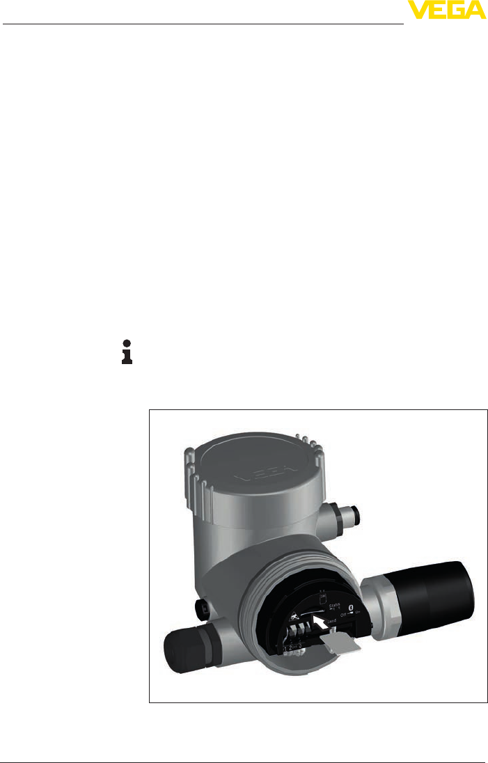
Insert the card (beveled side in front) into the card slot until it snaps in.
The contact surface must point upward.
Note:
The PLICSMOBILE T81 must be disconnected from voltage when
inserting the SIM card. Keep ESD protection in mind when handling
the SIM card. Electrostatic discharges can damage the SIM card or
the PLICSMOBILE.
Fig. 11: Insert Mini-SIM card
Measured value transmis-
sion
Insert SIM card

29
7 Setup
PLICSMOBILE T81/B81/S81 • External GSM/GPRS/UMTS radio unit
55234-EN-170206
To avoid misuse, the SIM card is generally locked by a PIN. To ensure
thatPLICSMOBILEcancontacttheselockedSIMcards,rstofall
thePINmustbeentered.Forthispurposetheassistant"Activate SIM
card"isavailableintheDTM.EnterherethecorrectPINforthecard.
TheassistantalsooerstheoptionofchangingthePIN.
Information:
When using the VEGA Ident Card, entering or deactivating a PIN is
not required.
Thencheckifthecardisloggedintothenetworkandifsucientnet-
work coverage (signal strength) exists. For a reliable measured value
transmission, a signal strength of at least 30 % should be displayed.
ThiscanbecheckedintheDTMmenu"Network information"under
"Setup - Diagnosis".Youcanalsoseethegeneraldevicestatusvia
the status indication.
The following operating conditions are signalled via the yellow LED
(mobile network status indication):
• LED does not light: no operating voltage or power saving mode
active
• Constantashing: Instrument is not logged into the GSM net-
work
• Unsteadyashing(longOFF/shortON): instrument is booked
into the GSM network
• Continuous light: Transmission or dial-up connection active
• Quicksteadyashingaftercontinuouslight Measured value
transmission failed
The following operating conditions are signalled via the blue LED
(Bluetooth status indication):
• LED does not light:Bluetoothswitchedoorpowersavingmode
active
• Unsteadyashing(longOFF/shortON): Bluetooth switched on
• Permanent light: Bluetooth connection is active
Information:
When the PLICSMOBILE T81 is in power saving mode, the LED
status indicators are inactive. The LED indicators are active only dur-
ing the time when a measurement with subsequent measured value
transmission takes place.
By pushing this button, a manual measured value transmission will be
triggered,independentoftheconguredtimesettings.Thisfunctions
also if PLICSMOBILE is in power saving mode. Here you can check
by means of the yellow status LED if logging into the GSM network is
possible.
7.5 Internet connection and measured value
transmission
The transmission of measured values via e-mail or to VEGA Inventory
System is always based on an internet connection. For GPRS con-
Activate SIM card
Status indication
"Send" button
Internet connection
30
7 Setup
PLICSMOBILE T81/B81/S81 • External GSM/GPRS/UMTS radio unit
55234-EN-170206
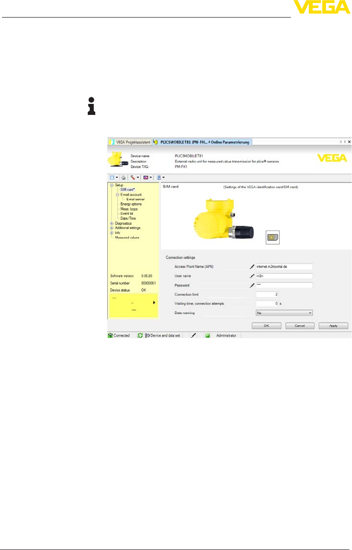
nection, access data (user name/password) and the respective APN
(Access Point Name) are required.
WhenusingtheVEGAservicepackage"Wireless data transmis-
sion"andtheVEGAInventorySystem,youneednoaccessdataor
additional information because the required parameters are already
preset.
Information:
Further information and a list of current mobile network providers
along with their access data can be found in the online help of the
PLICSMOBILE DTM.
Fig. 12: Entering the Internet access data
The measured values can be transmitted optionally in the following
ways:
• Via integrated mail client to any e-mail address
• Via SMS to any mobile phone
• Via http to the VEGA Inventory System
UndertheDTMmenuitem"Event list"thereisaconvenientassistant
for setting up measured value transmission. The measured values can
betransmittedatindividuallydenabletimesorintervals.Amessage
can also be triggered when a certain level is exceeded or underrun.
In addition, a status-controlled measured value transmission can be
carried out, for example when a fault signal occurs.
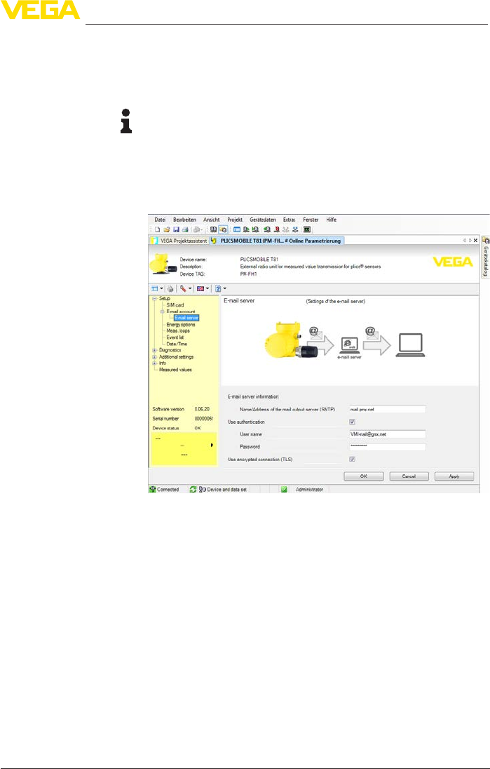
For this option, an e-mail account with the names of the inbox and
outbox servers (POP3/SMTP) as well as the user name/password are
required for authentication. These data are available from your e-mail
provider. For secure transmission, an encrypted connection via TLS
is preset. Please note that for encrypted connections, other server
Measured value transmis-
sion
E-mail transmission
31
7 Setup
PLICSMOBILE T81/B81/S81 • External GSM/GPRS/UMTS radio unit
55234-EN-170206
namesmustnormallybeused.Youcanndfurtherinformationinthe
online help of the PLICSMOBILE DTM.
The measurement data can be sent either directly in the e-mail or in
anattachedle.TheformatsTXT,CSV,HTMLorXMLareavailable.
Note:
If you also want to send e-mails while using the Inventory System and
a VEGA Ident Card, the following information is required in the con-
nection settings:
• Username:"m2m"
• Password:"sim"
• APN:"internet.m2mportal.de"
Fig. 13: Input of the e-mail access data
For measured value transmission via SMS, no additional access data
are required because all needed information is already available via
the mobile phone contract.
Fortheconguration,onlytheURLortheIPaddressoftheInven-
tory server are required. When hosting is carried out through VEGA,
theserveriscontactedviatheURL:"data-vis.vega.com".IfInventory
System is hosted in your company, you will get the URL from your IT
department.
SMS transmission
VEGA Inventory System

32
8Maintenanceandfaultrectication
PLICSMOBILE T81/B81/S81 • External GSM/GPRS/UMTS radio unit
55234-EN-170206
8 Maintenanceandfaultrectication
8.1 Maintenance
If the device is used properly, no special maintenance is required in
normal operation.
8.2 Rectify faults
The operator of the system is responsible for taking suitable meas-
ures to rectify faults.
Maximum reliability is ensured. Nevertheless, faults can occur during
operation. These may be caused by the following, e.g.:
• Measured value from sensor not correct
• Voltage supply
• Interference in the cables
Therstmeasurestobetakenaretochecktheinput/outputsignalas
well as to evaluate the error messages via the DTM. The procedure is
described below. In many cases, the causes can be determined and
thefaultsrectiedinthisway.
Should these measures not be successful, please call in urgent cases
the VEGA service hotline under the phone no. +49 1805 858550.
Thehotlineismanned7daysaweekround-the-clock.Sinceweoer
this service worldwide, the support is only available in the English
language. The service is free, only standard call charges are incurred.
Error Reason Rectication
No indi-
cation of
the signal
strength
No GSM network avail-
able
Check network availability via mo-
bile phone
E008 Sensor not found Check connection of the sensor
E013 Sensor signals error, no
valid measured value
Check sensor parameter adjustment
Send sensor for repair
E030 Sensor in boot phase
Measured value not valid
Check sensor parameter adjustment
E034 EEPROM CRC error Switchtheinstrumentoandon
Carry out a reset
Send instrument for repair
E035 ROM CRC error Switchtheinstrumentoandon
Carry out a reset
Send instrument for repair
E036 Instrument software not
executable (during soft-
ware update and after
failed update)
Waituntilsoftwareupdateisnished
Carry out another software update
Reaction when malfunc-
tion occurs
Causes of malfunction
Faultrectication
24 hour service hotline
Error messages

33
8Maintenanceandfaultrectication
PLICSMOBILE T81/B81/S81 • External GSM/GPRS/UMTS radio unit
55234-EN-170206
Error Reason Rectication
E042 Hardware error with self-
check
Send instrument for repair
E053 Sensor measuring range
is not read correctly
Communication error: Check sensor
cable and screening
E086 Error communication
hardware (initialisation of
the radio module failed)
Initialisation is carried out automatical-
ly. If the error exists permanently, send
instrument for repair
Depending on the reason for the fault and the measures taken, the
stepsdescribedinchapter"Set up"mayhavetobecarriedoutagain.
8.3 How to proceed if a repair is necessary
Youcanndaninstrumentreturnformaswellasdetailedinforma-
tion about the procedure in the download area of our homepage:
www.vega.com.
By doing this you help us carry out the repair quickly and without hav-
ing to call back for needed information.
If a repair is necessary, please proceed as follows:
• Printandlloutoneformperinstrument
• Clean the instrument and pack it damage-proof
• Attach the completed form and, if need be, also a safety data
sheet outside on the packaging
• Please contact the agency serving you to get the address for
thereturnshipment.Youcanndtheagencyonourhomepage
www.vega.com.
Note:
If a battery-operated instrument is returned for repair, the battery/
power pack must be removed. Please send only the instrument, not
the battery/power pack.
Reaction after fault recti-
cation

34
9 Dismount
PLICSMOBILE T81/B81/S81 • External GSM/GPRS/UMTS radio unit
55234-EN-170206
9 Dismount
9.1 Dismounting steps
Takenoteofchapters"Mounting"and"Connecting to power supply"
and carry out the listed steps in reverse order.
9.2 Disposal
The instrument consists of materials which can be recycled by spe-
cialised recycling companies. We use recyclable materials and have
designed the electronics to be easily separable.
Materials:seechapter"Technical data"
For disposal or recycling within the European Union proceed accord-
ingtothe"Electronics recycling"and"Battery/Accumulator recycling"
below. Outside the European Union you should take note of the valid
national regulations.
Electronics recycling
This instrument is not subject to the WEEE directive 2002/96/EG
and the respective national laws. Hence pass the instrument directly
on to a specialised recycling company and do not use the municipal
collecting points. These may be used only for privately used products
according to the WEEE directive.
Battery/accumulator recycling
Note:
The disposal is subject to the directive 2006/66/EG on batteries and
accumulators.
Batteries and accumulators contain some environmentally harm-
ful but also some valuable raw materials that can be recycled. For
that reason batteries and accumulators must not be disposed of in
household waste.
All users are legally obligated to bring spent batteries to a suitable
collection point, e.g. public collection points. You can also return the
batteries and accumulators to us for correct disposal. Due to the very
strict transport regulations for lithium-based batteries/accumulators,
this is normally not a good idea because shipment is very expensive.
Correctdisposalavoidsnegativeeectsonhumansandtheenviron-
ment and ensures recycling of useful raw materials.

35
10 Supplement
PLICSMOBILE T81/B81/S81 • External GSM/GPRS/UMTS radio unit
55234-EN-170206
10 Supplement
10.1 Technical data
General data PLICSMOBILE T81
Materials
ƲPlastic housing plastic PBT (Polyester)
ƲAluminium die-cast housing Aluminium die-casting AlSi10Mg, powder-coated - basis:
Polyester
ƲStainless steel housing 316L
ƲCable gland PA
ƲSealing, cable gland NBR
ƲBlind plug, cable gland PA
ƲSeal between housing and housing lid Silicone SI 850 R, NBR silicone-free
ƲGround terminal 316L
Weight
ƲPlastic housing approx. 1.18 kg (2.59 lbs)
ƲAluminium housing approx. 1.65 kg (3.65 lbs)
ƲStainless steel housing approx. 3 kg (6.61 lbs)
Power supply PLICSMOBILE T81
Operating voltage1) 9.6 … 32 V DC
Power consumption2)
ƲPower saving mode (9 V/12 V) 0.18 mW/0.3 mW
ƲPower saving mode (24 V/32 V) 1.8 mW/3.7 mW
ƲPermanent operation 1.1 W
ƲPeak power (measured value trans-
mission)
5.1 W
Power requirement3)
ƲMeasurement cycle incl. transmission 15 mWh
Sensor power supply
Ʋ O-loadvoltage 34 V (31 V with Ex version)
ƲMax. current 80 mA (26 mA with Ex version)
PLICSMOBILE B81
Materials
ƲAluminium housing Aluminium die-casting
ƲCable gland PA
ƲSealing, cable gland NBR
1) When the instrument is powered by an external voltage supply, make sure the voltage supply unit has a suf-
cientcurrentcarryingcapacity.Withavoltagesupply<9.6V,currentpeaksofupto2Amustbeexpected.
2) ThelistedpowerspecicationsincludethevoltagesupplyofaHARTsensorwith20mA.
3) The listed energy requirement includes the voltage supply of a HART sensor (VEGAPULS 61 with 4 mA (multi-
drop mode) and 12 V operating voltage.

36
10 Supplement
PLICSMOBILE T81/B81/S81 • External GSM/GPRS/UMTS radio unit
55234-EN-170206
ƲBlind plug, cable gland PA
ƲSeal between housing and housing lid Silicone SI 850 R, NBR silicone-free
ƲGround terminal 316L
Weight
ƲAluminium housing approx. 1.66 kg (3.66 lbs)
Approved battery types Lithium battery or NiMH accumulator
Battery format Type D (Mono)
Necessary power supply for charging
NiMH accumulators
20 … 32 V DC
NiMH accumulator
Accumulator type 4x NiMH series D (Mono)
Manufacturer Ansmann
VEGA order code 2.54971
Capacitance 10 Ah
Nominal voltage 1.2 V DC
Ambient temperature (discharging) -20… +60 °C (-4 … +140 °F)
Charging temperature 0 … +45 °C (+32 … +113 °F)4)
Lithium battery
Battery type 4x Lithium battery series D (Mono)
Manufacturer/Type Saft LSH 20
VEGA order code 2.54970
Capacitance 13 Ah
Nominal voltage 3.6 V DC
Ambient temperature -40… +85 °C (-40 … +185 °F)
PLICSMOBILES81(solarpanel)
Solar module 5 W
ƲNominal voltage 17.8 V DC
Ʋmax. open circuit voltage 22 V DC
ƲNominal current 0.285 A
Ʋmax. shortcircuit current 0.315 A
ƲDimensions 401 x 176 x 35 mm (15.8 x 6.9 x 1.3 in)
Solar module 20 W
ƲNominal voltage 17.8 V DC
Ʋmax. open circuit voltage 22 V DC
ƲNominal current 1.14 A
Ʋmax. shortcircuit current 1.27 A
ƲDimensions 662 x 299 x 35 mm (26.1 x 11.8 x 1.3 in)
4) Due to a protective circuit, charging outside this temperature range is not possible

37
10 Supplement
PLICSMOBILE T81/B81/S81 • External GSM/GPRS/UMTS radio unit
55234-EN-170206
Connection cable
ƲLength 5/10/25 m (196/393/ in)
ƲWire cross-section 2 x 0.5 mm² (AWG 20)
ƲMaterial, cable cover PVC
Sensor input
Number of sensors 15 x HART sensors (5 x with Ex version)
Terminal voltage
ƲNon-Ex version approx. 14 V with 15 sensors (60 mA)
ƲEx version approx. 14 V with 5 sensors (20 mA)
Current limitation approx. 80 mA (26 mA with Ex)
Mobile network
SIM card slot Mini-SIM (25 x 15 mm)
Radio frequency UMTS Quad-Band GSM (850/900/1800/1900 MHz)
Antenna version Isotropic (Omni) antenna
Bluetooth
Bluetooth standard Bluetooth Smart (Bluetooth LE)
Participants max. 1
Max.eectiverange 25 m (82.02 ft)
Indicators
LED displays
ƲStatus, mobile network 1 x LED yellow
ƲStatus, Bluetooth 1 x LED blue
Electromechanical data
Cable entry/plug
ƲElectronics housing – 1 x cable gland M20 x 1.5 (cable ø 5 … 9 mm), 1 x
plug for sensor connection
Spring-loaded terminals for wire cross-section
ƲMassive wire, stranded wire 0.2 … 2.5 mm² (AWG 24 … 14)
ƲStranded wire with end sleeve 0.2 … 1.5 mm² (AWG 24 … 16)
Sensor connection cable
ƲLength 5/10/25 m
Ambient conditions
Ambient temperature -25 … +60 °C (-13 … +140 °F)
Storage and transport temperature -25 … +80 °C (-13 … +176 °F)
Electrical protective measures
Protection rating IP 665)
5) A suitable cable is required for maintaining the protection rating.

38
10 Supplement
PLICSMOBILE T81/B81/S81 • External GSM/GPRS/UMTS radio unit
55234-EN-170206
Overvoltage category (IEC 61010-1)
Ʋup to 2000 m (6562 ft) above sea level II
Ʋup to 5000 m (16404 ft) above sea
level
II (only with connected overvoltage protection)
Ʋup to 5000 m (16404 ft) above sea
level
I
Protection rating (IEC 61010-1) II
Measures for electrical separation
Reliable separation according to VDE 0106, Part 1, between power supply and input
ƲReference voltage 50 V
ƲVoltage resistance of the insulation 1.5 kV
Radio approvals
Radio approvals GSM modem
ƲFCC ID RI7GE865
ƲIC (Industry Canada) 5131 A-GE865
Radio approvals Bluetooth module
ƲFCC ID P144BL600
ƲIC (Industry Canada) 19318-BL600
Approvals
Instrumentswithapprovalscanhavedierenttechnicalspecicationsdependingontheversion.
For that reason the associated approval documents of these instruments have to be carefully
noted.Theyarepartofthedeliveryorcanbedownloadedunder"www.vega.com"via"VEGA
Tools"and"Instrument search"aswellasvia"Downloads"and"Approvals".
39
10 Supplement
PLICSMOBILE T81/B81/S81 • External GSM/GPRS/UMTS radio unit
55234-EN-170206
10.2 Dimensions
~ 110 mm (4.33")
ø 79 mm
(3.31")
113 mm (4.44")
5 mm (0.20")
85 mm (3.35")
ø 60 mm
(2.36")
16 mm
(0.63")
~ 113 mm (4.45")
ø 86 mm
(3.39")
120 mm (4.72")
5 mm (0.20")
85 mm (3.35")
ø 60 mm
(2.36")
11 mm
(0.43")
~ 178 mm (7.01")
~ 186 mm (7.32")
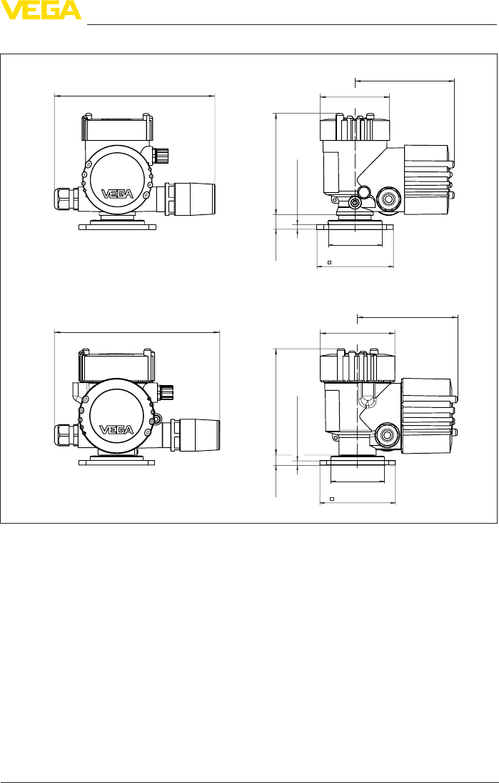
Fig. 14: Dimensions PLICSMOBILE T81 with plastic housing and StSt/Aluminium housing
40
10 Supplement
PLICSMOBILE T81/B81/S81 • External GSM/GPRS/UMTS radio unit
55234-EN-170206
57 mm
(2.24") 57 mm
(2.24")
62 mm
(2.44")
83,5 mm
(3.29")
7,5 mm
(0.29")
25 mm
(0.98")
107 mm
(4.22")
35 mm
(1.38")
ø 6,9 mm
(0.27")
61,5 mm
(2.42")
70 mm
(2.76")
ø 110 mm
(4.33")
127 mm
(5.00")
145 mm
(5.71")
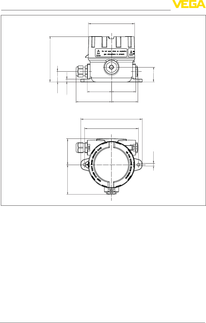
Fig. 15: Dimensions PLICSMOBILE B81 with Aluminium housing

41
10 Supplement
PLICSMOBILE T81/B81/S81 • External GSM/GPRS/UMTS radio unit
55234-EN-170206
10.3 Industrial property rights
VEGA product lines are global protected by industrial property rights. Further information see
www.vega.com.
VEGA Produktfamilien sind weltweit geschützt durch gewerbliche Schutzrechte.
Nähere Informationen unter www.vega.com.
Les lignes de produits VEGA sont globalement protégées par des droits de propriété intellec-
tuelle. Pour plus d'informations, on pourra se référer au site www.vega.com.
VEGA lineas de productos están protegidas por los derechos en el campo de la propiedad indus-
trial. Para mayor información revise la pagina web www.vega.com.
Линии продукции фирмы ВЕГА защищаются по всему миру правами на интеллектуальную
собственность. Дальнейшую информацию смотрите на сайте www.vega.com.
VEGA系列产品在全球享有知识产权保护。
进一步信息请参见网站<www.vega.com。
10.4 Hash function acc. to mbed TLS
mbedTLS:Copyright(C)2006-2015,ARMLimited,AllRightsReservedSPDX-License-Identier:
Apache-2.0
LicensedundertheApacheLicense,Version2.0(the"License");youmaynotusethis
leexceptincompliancewiththeLicense.YoumayobtainacopyoftheLicenseat
http://www.apache.org/licenses/LICENSE-2.0.
Unless required by applicable law or agreed to in writing, software distributed under the License is
distributedonan"ASIS"BASIS,WITHOUTWARRANTIESORCONDITIONSOFANYKIND,either
expressorimplied.SeetheLicenseforthespeciclanguagegoverningpermissionsandlimitations
under the License.
10.5 Trademark
All the brands as well as trade and company names used are property of their lawful proprietor/
originator.

42
INDEX
PLICSMOBILE T81/B81/S81 • External GSM/GPRS/UMTS radio unit
55234-EN-170206
INDEX
A
Access data 29, 30
Access number 29
Accumulator 9, 19
Accumulator capacity 22
Adjustment 26
APN 29
Application area 9
B
Battery 9, 19
Battery capacity 22
Battery chamber 19
Bluetooth 24, 25
Bluetooth USB adapter 26
C
Cable
– Grounding 14
– Shielding 14
Carrier rail 12
Causes of malfunction 32
Connection procedure 16
Connection technology 15
CSD 27, 29
D
Data block rounding 28
Data matrix code 8
Dial-Out 27
Dial-up connection 27
Documentation 8
DTM 9, 25, 26
– DTM Collection 26
– Full version 26
E
E-mail 9, 30
F
Fault
– Rectication32
FDT 26
G
GPRS 9, 27, 28, 29
GSM 9
H
HART 24
I
Instrument return form 33
Inventory System 30
L
LED displays 29
Lithium battery 19
M
M2M 28
Measured value transmission 19, 23, 29, 30
Moisture 11
Mounting 11
– Carrier rail mounting 12
– Tube 12
– Wall mounting 11
Mounting options 30
Multidrop 24
Multiviewer 26
N
Network coverage 29
O
Online help 26
Operating instructions 8
Orientation, solar module 20
P
PACTware 9, 25
PIN 29
Plug 15
Power options 23
Power saving function 9
Power saving mode 19, 22, 23, 27, 28, 29
Power supply unit 19
Q
Quadband 9
R
Remote parameter adjustment 9, 23, 27
Repair 33
Roaming 27, 28
S
Self-discharge 22
Sensor connection cable 15
Serial number 8
Service hotline 32

43
INDEX
PLICSMOBILE T81/B81/S81 • External GSM/GPRS/UMTS radio unit
55234-EN-170206
Signal strength 29
SIM card 27, 29
Smartphone-App 8
SMS 9
Software update 26
Solar module 20
Standby 22
Status indications 29
T
Tank calculation 26
Tube holder 20
Type label 8
V
VEGA Inventory System 9
Visualization 9
VMI 9
Voltage supply 9, 15

Printing date:
VEGA Grieshaber KG
Am Hohenstein 113
77761 Schiltach
Germany
55234-EN-170206
All statements concerning scope of delivery, application, practical use and operat-
ing conditions of the sensors and processing systems correspond to the information
available at the time of printing.
Subject to change without prior notice
© VEGA Grieshaber KG, Schiltach/Germany 2017
Phone +49 7836 50-0
Fax +49 7836 50-201
E-mail: info.de@vega.com
www.vega.com