VEGA Grieshaber KG PS60XW1 VEGAPULS 69 Level Probing Radar User Manual 77 GHz 031517
VEGA Grieshaber KG VEGAPULS 69 Level Probing Radar Users Manual 77 GHz 031517
Contents
- 1. Users Manual Rev 3
- 2. Users Manual 77 GHz 031517
Users Manual 77 GHz 031517

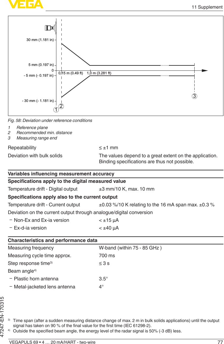
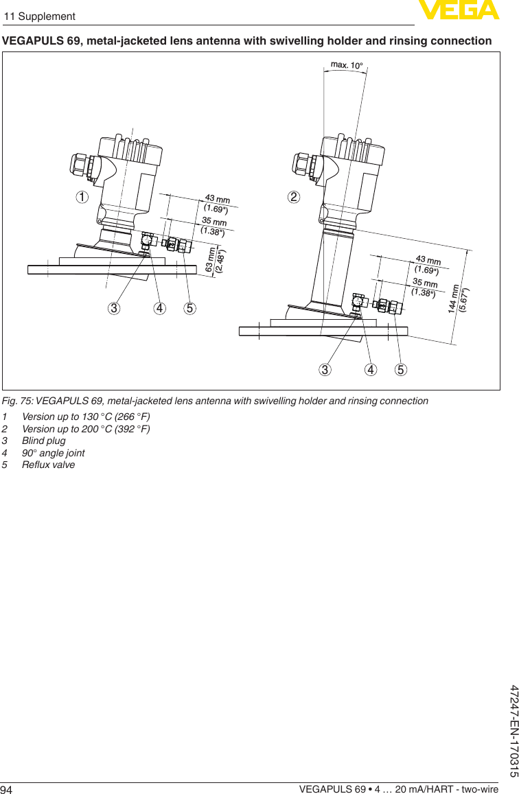
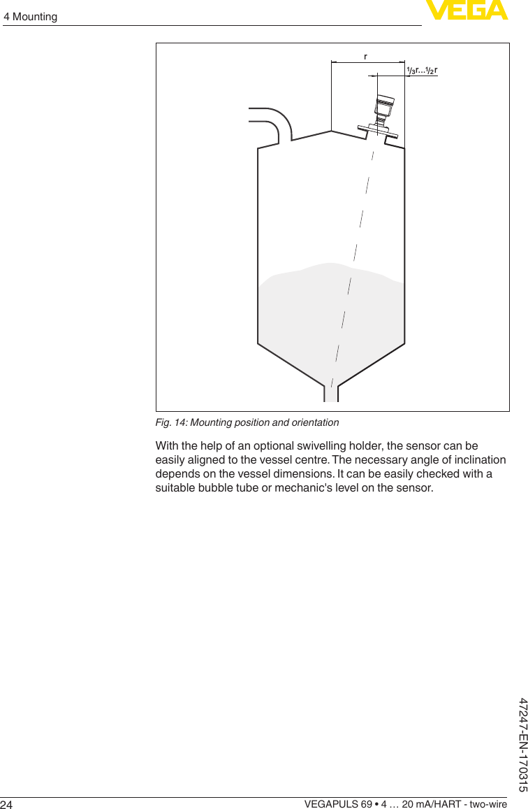
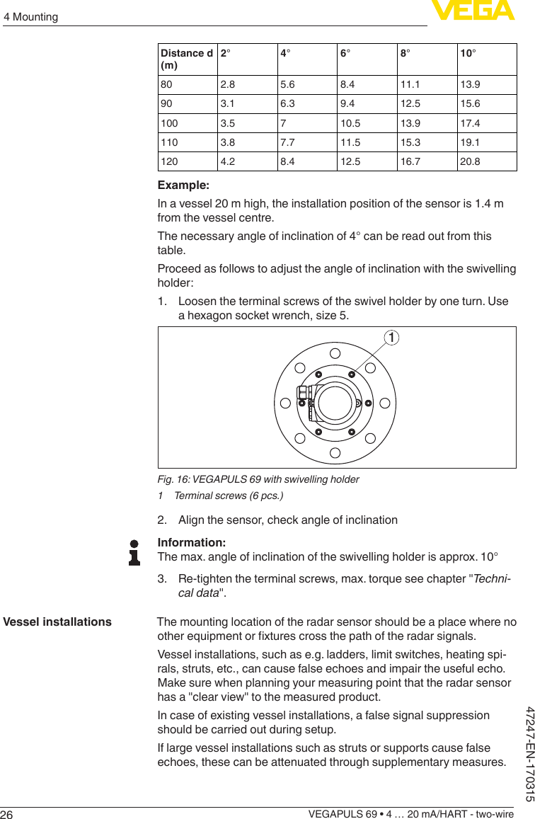
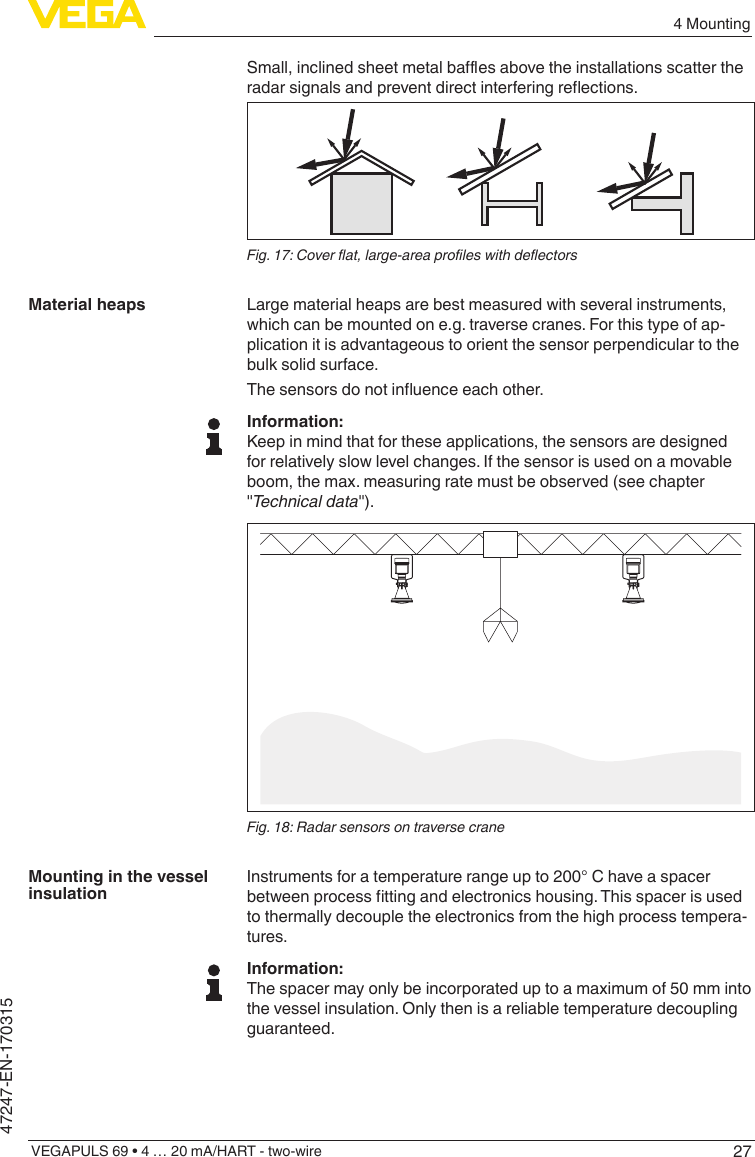
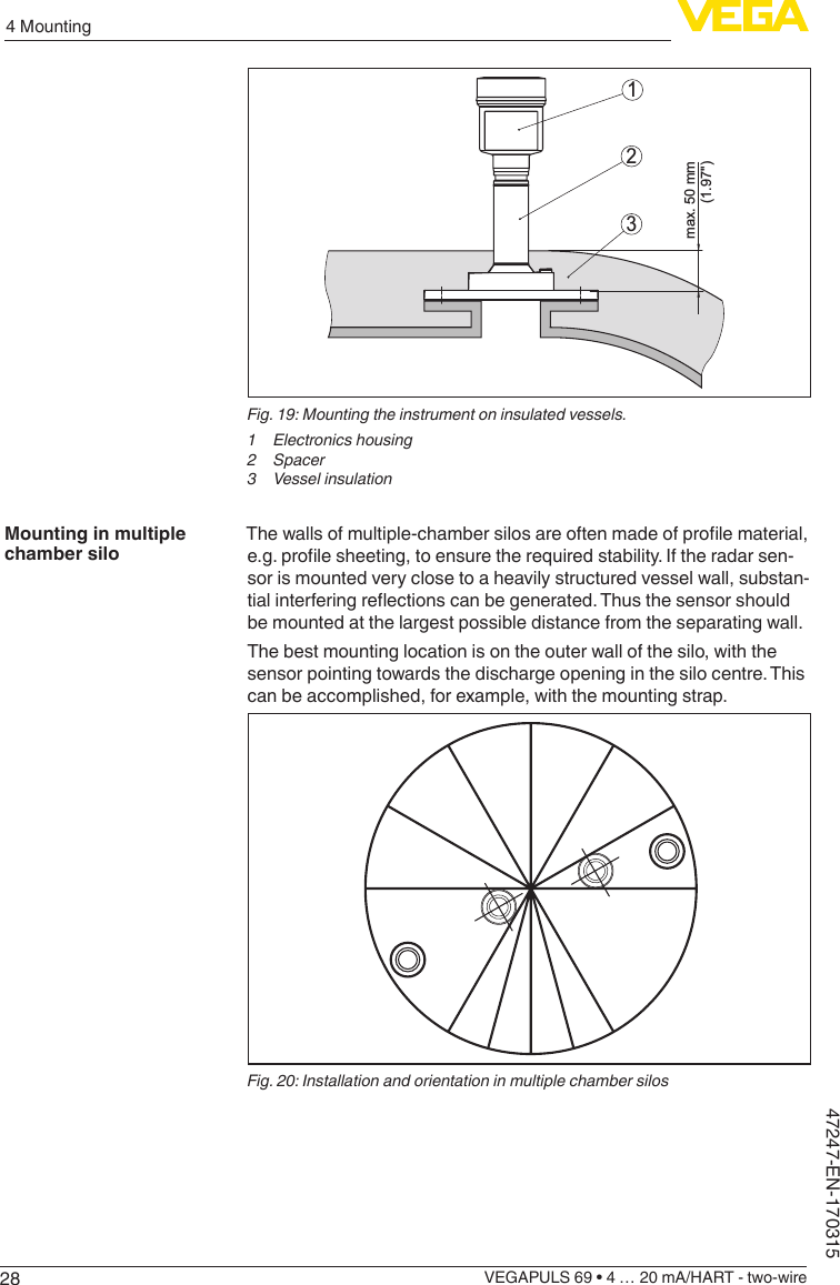
![92 For your safetyVEGAPULS 69 • 4 … 20 mA/HART - two-wire47247-EN-170315• L’utilisateur de l’appareil doit accepter tout brouillage radioélect-rique subi, même si le brouillage est susceptible d’en compromet-tre le fonctionnement.Cet appareil est homologué pour une utilisation dans les cuves fer-mées et les environnements ouverts avec les restrictions suivantes :• Cuves fermées: Pour les installations impliquant une inclinaison lors de l'installation : cet appareil ne doit être installé que dans une cuve totalement fermée en métal ou en béton, pour empêcher les émissions RF susceptibles d'interférer avec la navigation aéro-nautique. L'angle d'inclinaison maximum autorisé est de 10°. From electronics index .-03 the use in containers made of reinforced berglassisalsopermitted.• Environnement ouvert : Pour l'utilisation hors des cuves fermées, la condition suivante doit être remplie : L'appareil doit être installé et entretenu de manière à garantir une orientation verticale vers le bas du faisceau principal de l’antenne émettrice. De plus, l’utilisation de tout mécanisme ne permettant pas l’orientation ver-ticale vers le bas du faisceau principal de l’émetteur est interdite• Il est uniquement autorisé d'utiliser la version d'appareil avec le letageG1½ou1½NPTenenvironnementsouvertes.• L’installationd’undispositifLPRouTLPRdoitêtreeectuéepardesinstallateursqualiés,enpleineconformitéaveclesinstruc-tions du fabricant.• Cetappareilnedoitêtreinstalléqu'àdesemplacementsxes.L’appareil LPR ne doit pas être utilisé pendant qu’il est en train d’être déplacé ou se trouve dans un conteneur en mouvement.• Les applications portables sont interdites.• La vente à des particuliers est interdite• Ce dispositif ne peut être exploité qu'en régime de non-brouillage et de non-protection, c'est-à-dire que l'utilisateur doit accepter que des radars de haute puissance de la même bande de fréquences puissent brouiller ce dispositif ou même l'endommager. D'autre part, les capteurs de niveau qui perturbent une exploitation autori-sée par licence de fonctionnement principal doivent être enlevés aux frais de leur utilisateur.• La personne qui installe/utilise ce capteur de niveau doit s'assurer qu'il se trouve à au moins 10 km de l'Observatoire fédéral de radioastrophysique (OFR) de Penticton en Colombie-Britannique. Lescoordonnéesdel'OFRsont:latitudeN49°19′15″,longitudeO119°37′12″.Lapersonnequiinstalle/utiliseundispositifnepouvant respecter cette distance de 10 km (p. ex. dans la vallée de l'Okanagan [Colombie-Britannique]) doit se concerter avec le directeurdel'OFRand’obtenirdesapartuneautorisationécriteavant que l'équipement ne puisse être installé ou mis en marche. Le directeur de l'OFR peut être contacté au 250-497-2300 (tél.) ou au 250-497-2355 (fax). (Le Directeur des Normes réglementaires d'Industrie Canada peut également être contacté).2.10 Environmental instructionsProtection of the environment is one of our most important duties. That is why we have introduced an environment management system](https://usermanual.wiki/VEGA-Grieshaber-KG/PS60XW1.Users-Manual-77-GHz-031517/User-Guide-3326540-Page-9.png)

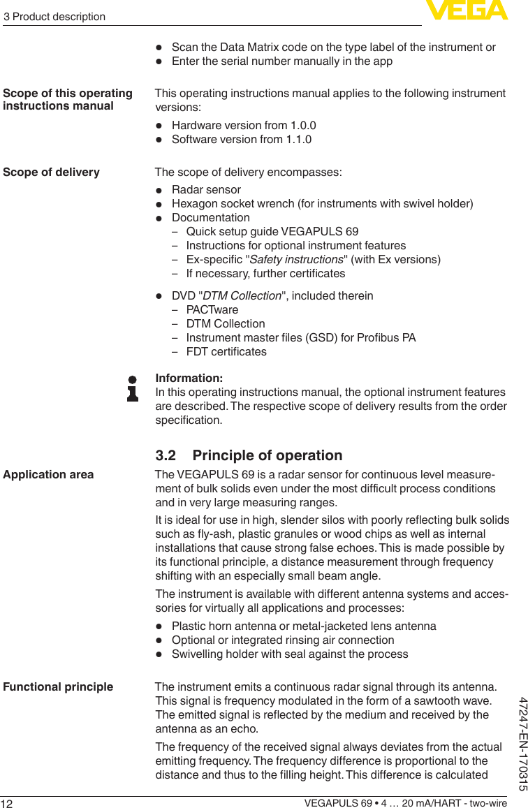
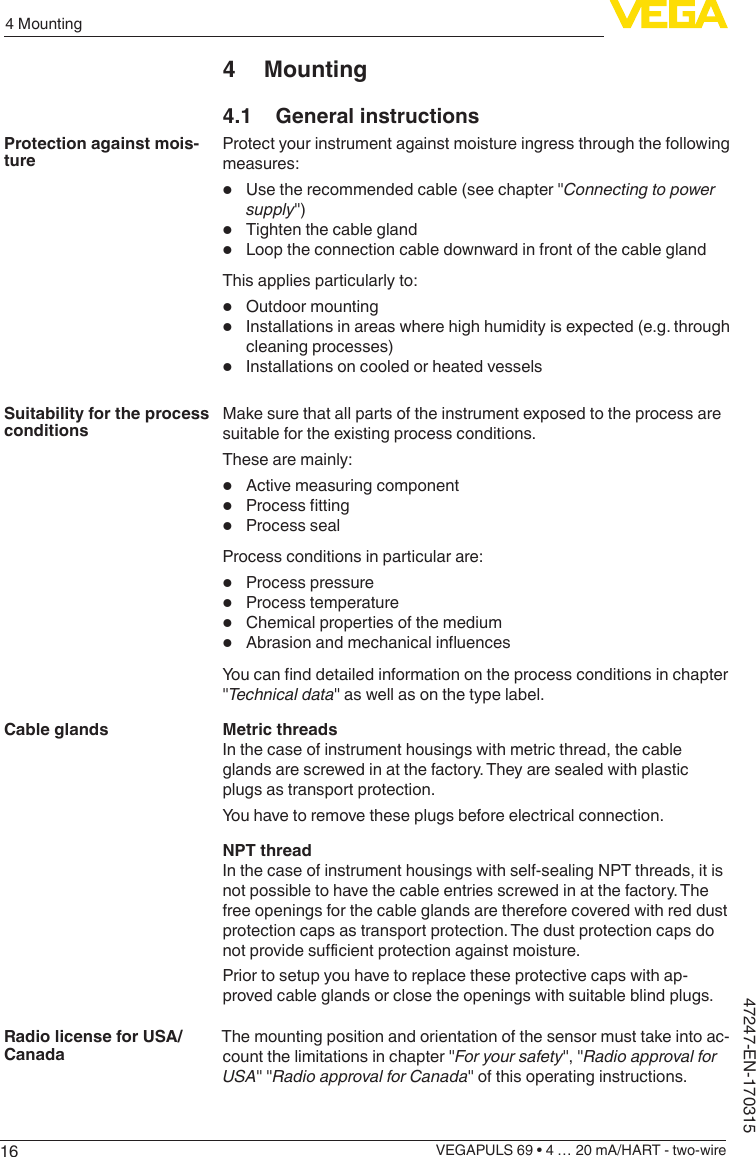


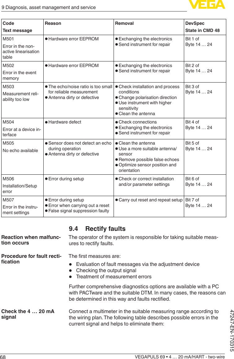
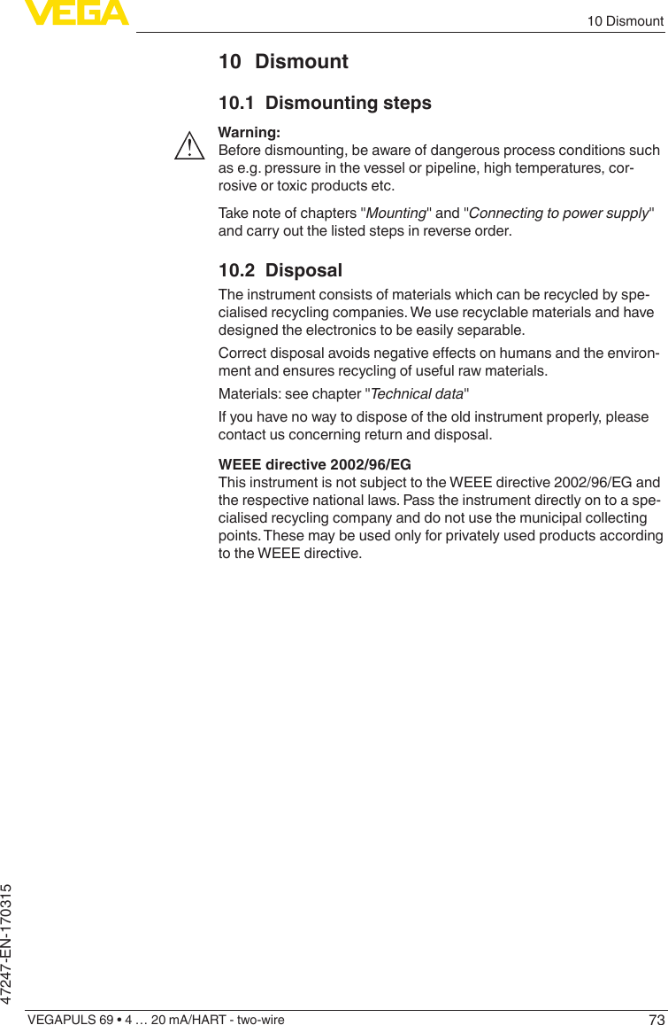
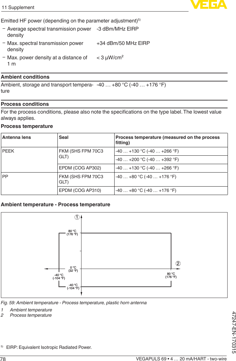
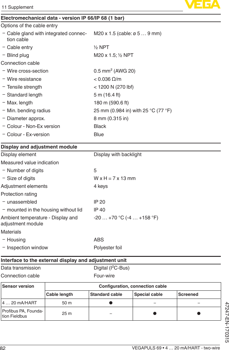
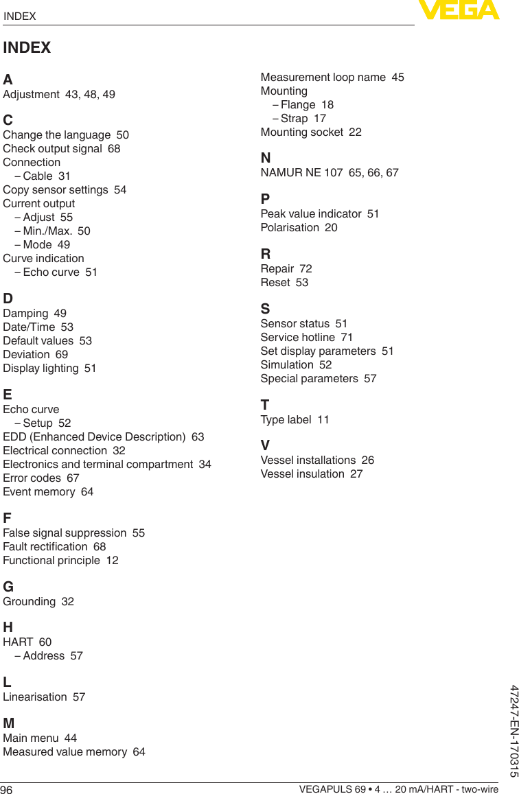
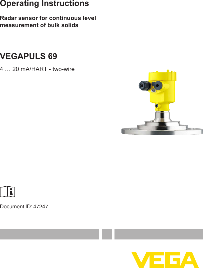
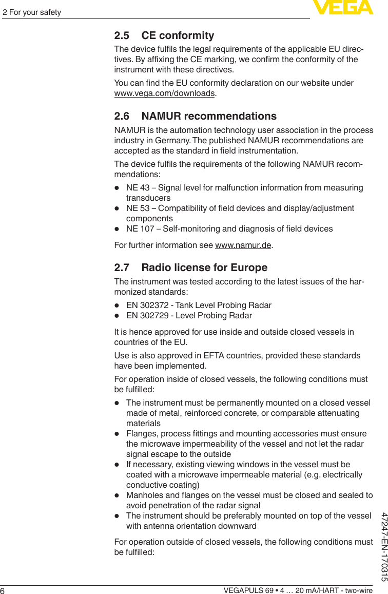
![426 Set up with the display and adjustment moduleVEGAPULS 69 • 4 … 20 mA/HART - two-wire47247-EN-1703151 2Fig. 41: Installing the display and adjustment module in the double chamber housing1 In the electronics compartment2 In the terminal compartmentNote:Ifyouintendtoretrottheinstrumentwithadisplayandadjustmentmodule for continuous measured value indication, a higher lid with an inspection glass is required.6.2 Adjustment system12Fig. 42: Display and adjustment elements1 LCdisplay2 Adjustment keys• [OK] key:Key functions](https://usermanual.wiki/VEGA-Grieshaber-KG/PS60XW1.Users-Manual-77-GHz-031517/User-Guide-3326540-Page-42.png)
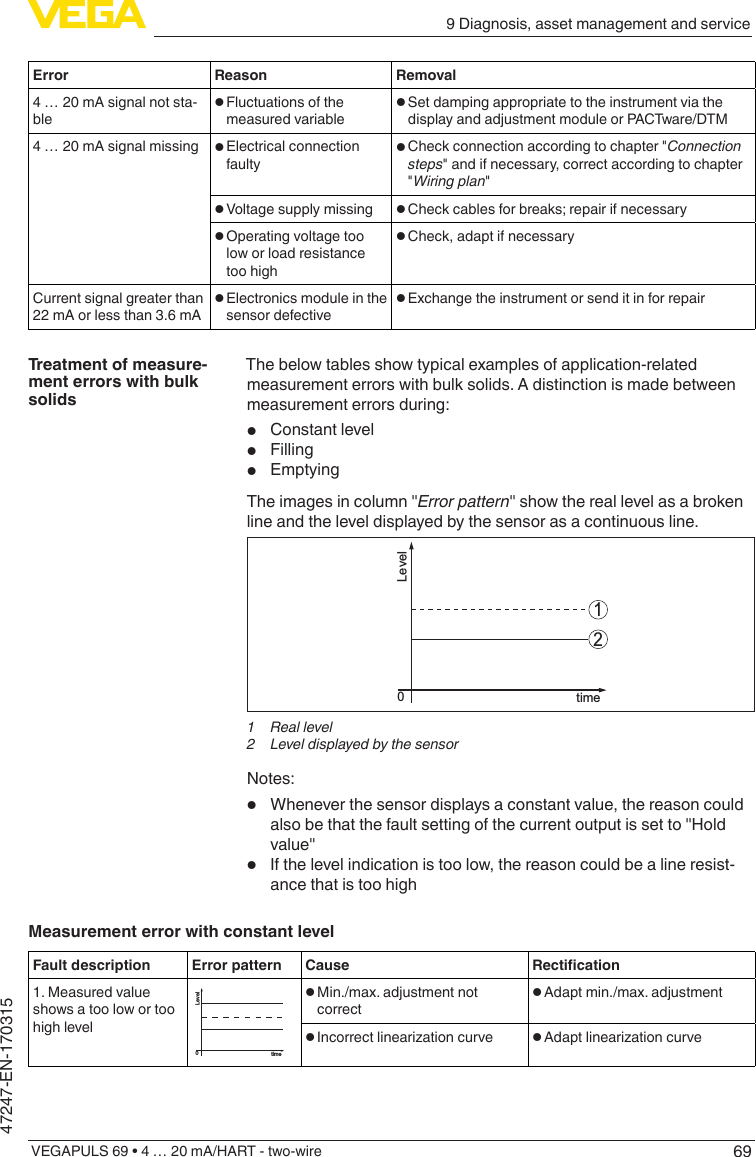
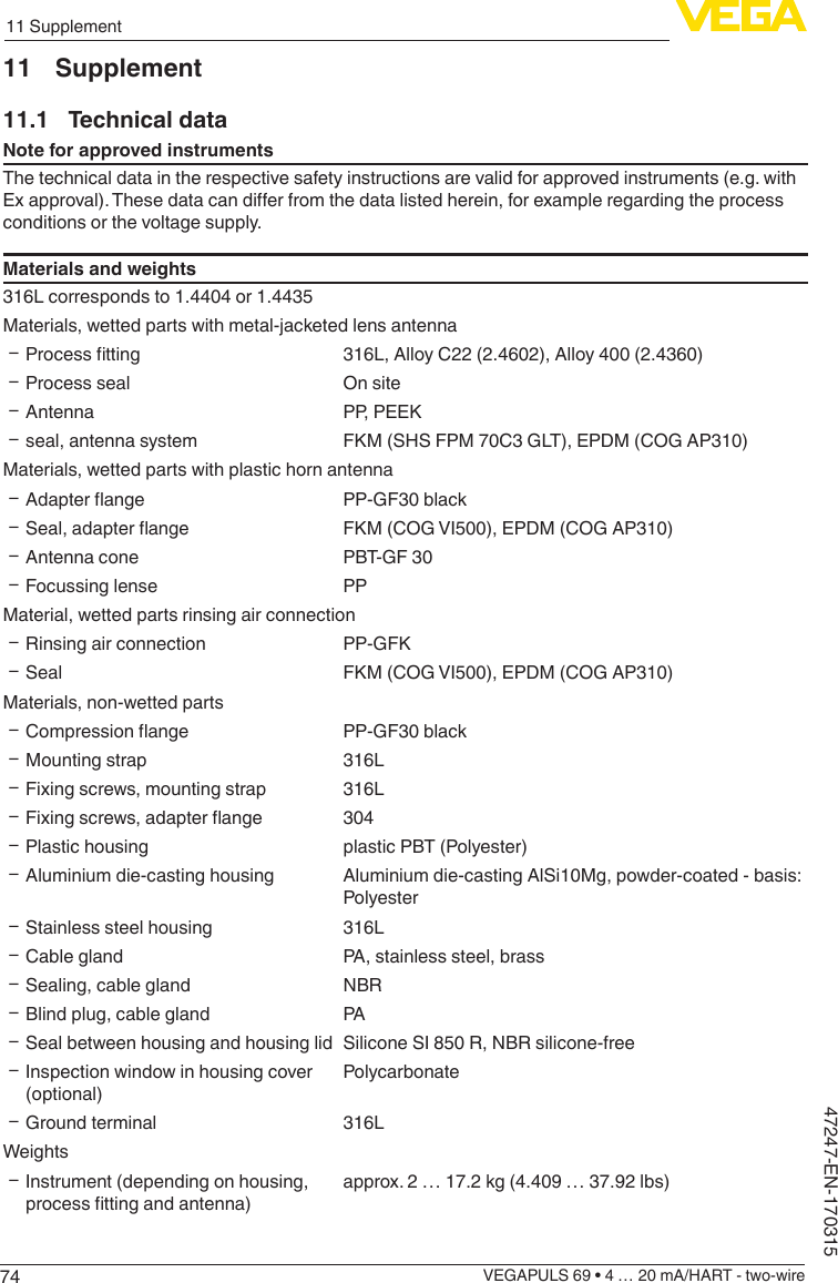
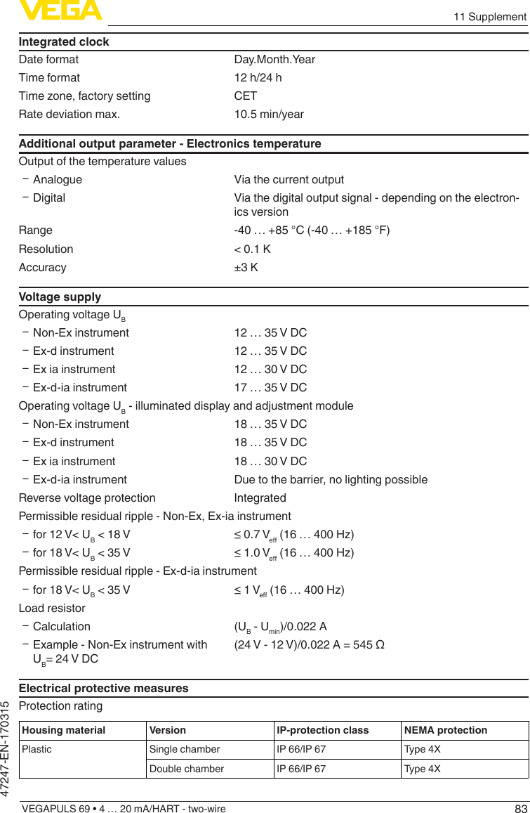
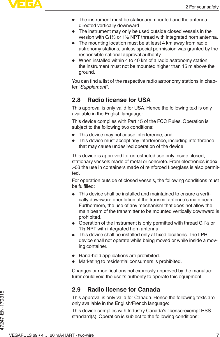
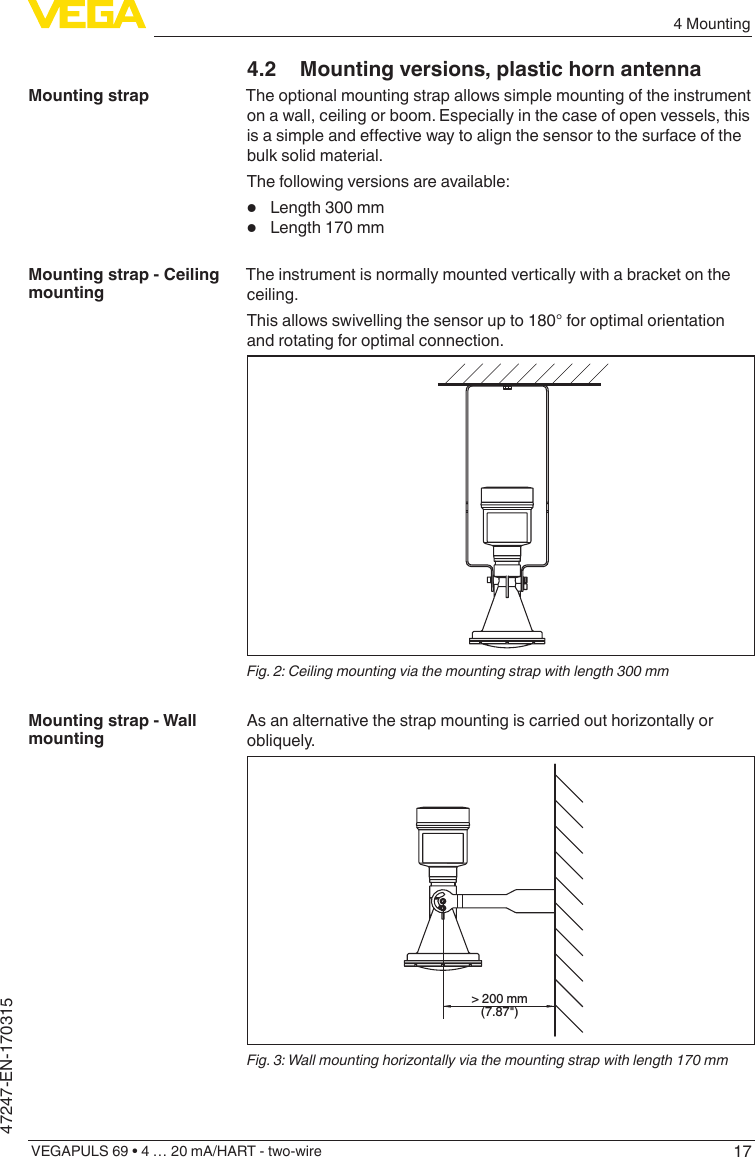
![436 Set up with the display and adjustment moduleVEGAPULS 69 • 4 … 20 mA/HART - two-wire47247-EN-170315 – Move to the menu overview – Conrmselectedmenu – Edit parameter – Save value• [->] key: – Change measured value presentation – Select list entry – Select menu items in the quick setup menu – Select editing position• [+] key: – Change value of the parameter• [ESC] key: – Interrupt input – Jump to next higher menuThe instrument is operated via the four keys of the display and adjustment module. The individual menu items are shown on the LC display.Youcanndthefunctionoftheindividualkeysinthepreviousillustration.When the [+] and [->] keys are pressed quickly, the edited value, or the cursor, changes one value or position at a time. If the key is pressed longer than 1 s, the value or position changes continuously.When the [OK] and [ESC] keys are pressed simultaneously for more than 5 s, the display returns to the main menu. The menu language is then switched over to "English".Approx. 60 minutes after the last pressing of a key, an automatic reset tomeasuredvalueindicationistriggered.Anyvaluesnotconrmedwith [OK] will not be saved.6.3 Measured value indication - Selection of national languageWith the [->]keyyoumovebetweenthreedierentindicationmodes.Intherstview,theselectedmeasuredvalueisdisplayedinlargedigits.In the second view, the selected measured value and a correspond-ing bar graph presentation are displayed.In the third view, the selected measured value as well as a second se-lectable value, e.g. the temperature of the electronics, are displayed.During the initial setup of an instrument shipped with factory settings, use the "OK" key to get to the menu "National language".Adjustment systemTime functionsMeasured value indica-tion](https://usermanual.wiki/VEGA-Grieshaber-KG/PS60XW1.Users-Manual-77-GHz-031517/User-Guide-3326540-Page-43.png)
![446 Set up with the display and adjustment moduleVEGAPULS 69 • 4 … 20 mA/HART - two-wire47247-EN-170315This menu item is used to select the national language for further pa-rameter adjustment. You can change the selection via the menu item "Setup - Display, Menu language".With the "OK" key you move to the main menu.6.4 Parameter adjustment - Quick setupTo quickly and easily adapt the sensor to the application, select the menu item "Quick setup" in the start graphic on the display and adjustment module.Select the individual steps with the [->] key.After the last step, "Quick setup terminated successfully" is displayed briey.Information:The echo curve of setup is stored automatically during the quick setup.The return to the measured value indication is carried out through the [->] or [ESC] keys or automatically after 3 sYoucannd"Extendedadjustment" in the next sub-chapter.6.5 Parameter adjustment - Extended adjustmentThemainmenuisdividedintovesectionswiththefollowingfunc-tions:Setup: Settings, e.g., for measurement loop name, units, application, adjustment, signal outputDisplay: Settings, e.g., for language, measured value display, lightingDiagnosis: Information, for example, on device status, peak value, simulation, echo curveAdditional adjustments: Date/Time, reset, copy function, scaling, currentoutput,falsesignalsuppression,linearization,HARTmode,special parametersInfo: Instrument name, hardware and software version, calibration date, instrument featuresIn the main menu item "Setup", the individual submenu items should be selected one after the other and provided with the correct Selection of national languageMain menu](https://usermanual.wiki/VEGA-Grieshaber-KG/PS60XW1.Users-Manual-77-GHz-031517/User-Guide-3326540-Page-44.png)
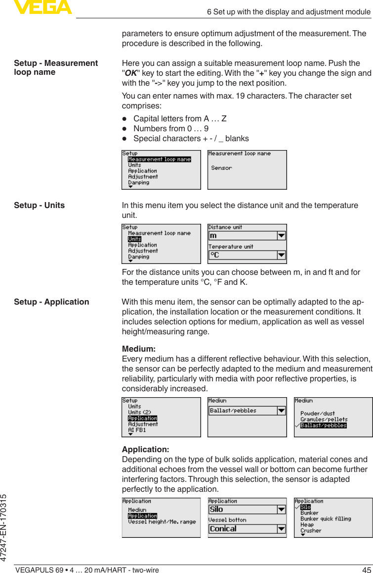
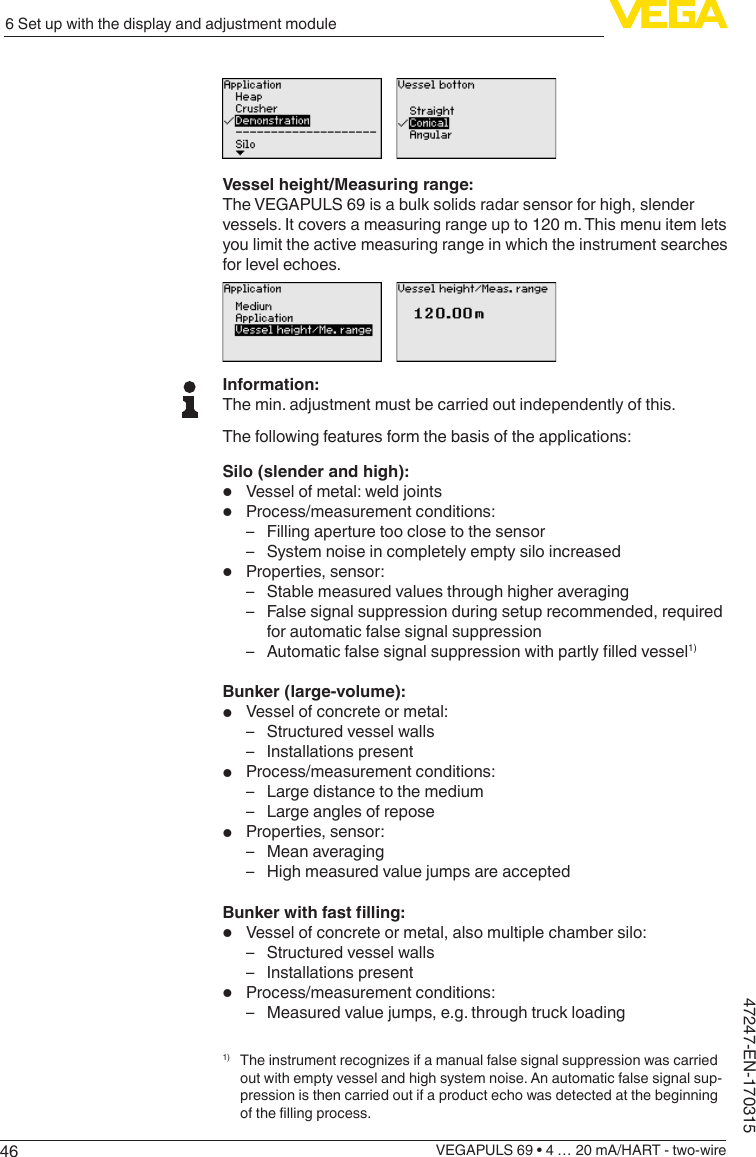
![476 Set up with the display and adjustment moduleVEGAPULS 69 • 4 … 20 mA/HART - two-wire47247-EN-170315 – Large distance to the medium – Large angles of repose• Properties, sensor: – Lower averaging – Very high measured value jumps are acceptedHeap:• Sensor mounting on movable conveyor belts• Detectionoftheheapprole• Heightdetectionduringlling• Process/measurement conditions: – Measuredvaluejumps,e.g.bytheproleoftheheaportrav-erses – Large angles of repose – Measurementnearthellingstream• Properties, sensor: – Mean averaging – High measured value jumps are acceptedCrusher:• Vessel: installations, wear and protective facilities available• Process/measurement conditions: – Measured value jumps, e.g. through truck loading – Fast reaction time – Large distance to the medium• Properties, sensor: – Little averaging – Max. reaction speed, very high measured value jumps are acceptedDemonstration:• Adjustment for all applications which are not typically level meas-urement – Instrument demonstration – Object recognition/monitoring (additional settings required)• Properties, sensor: – Sensor accepts all measured value changes within the measur-ing range immediately – High sensitivity to interference, because virtually no averagingEnter the requested parameters via the appropriate keys, save your settings with [OK] and jump to the next menu item with the [ESC] and the [->] key.Since the radar sensor is a distance measuring instrument, the distance from the sensor to the product surface is measured. To indicate the actual level, an allocation of the measured distance to the percentage height must be carried out.To perform the adjustment, enter the distance with full and empty ves-sel, see the following example:Setup - Adjustment](https://usermanual.wiki/VEGA-Grieshaber-KG/PS60XW1.Users-Manual-77-GHz-031517/User-Guide-3326540-Page-47.png)
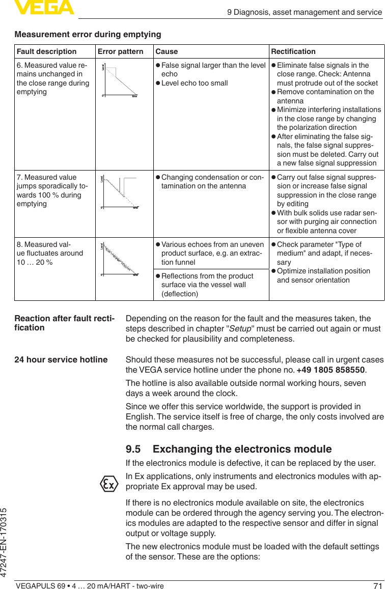
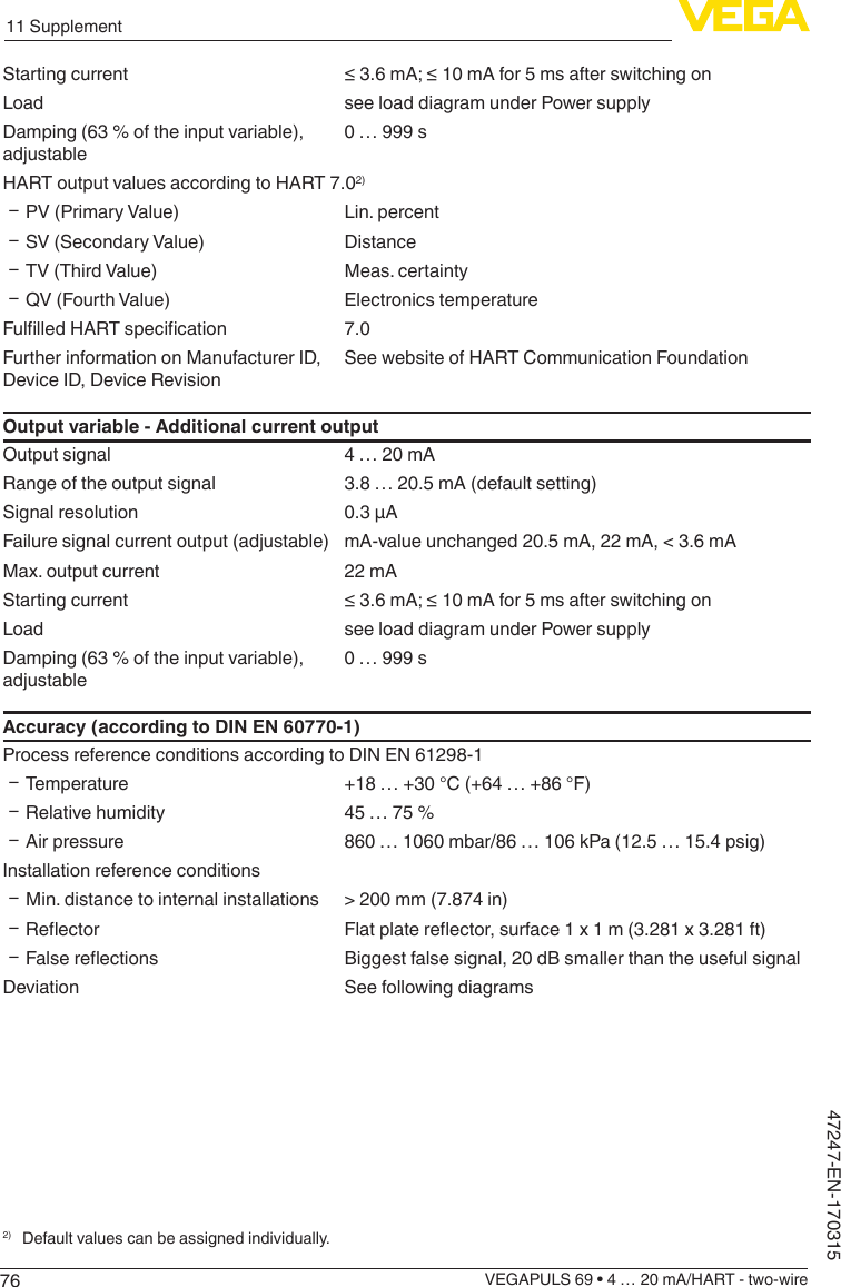
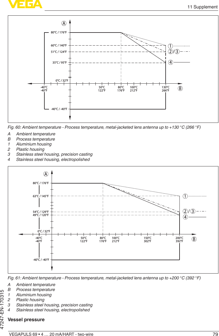
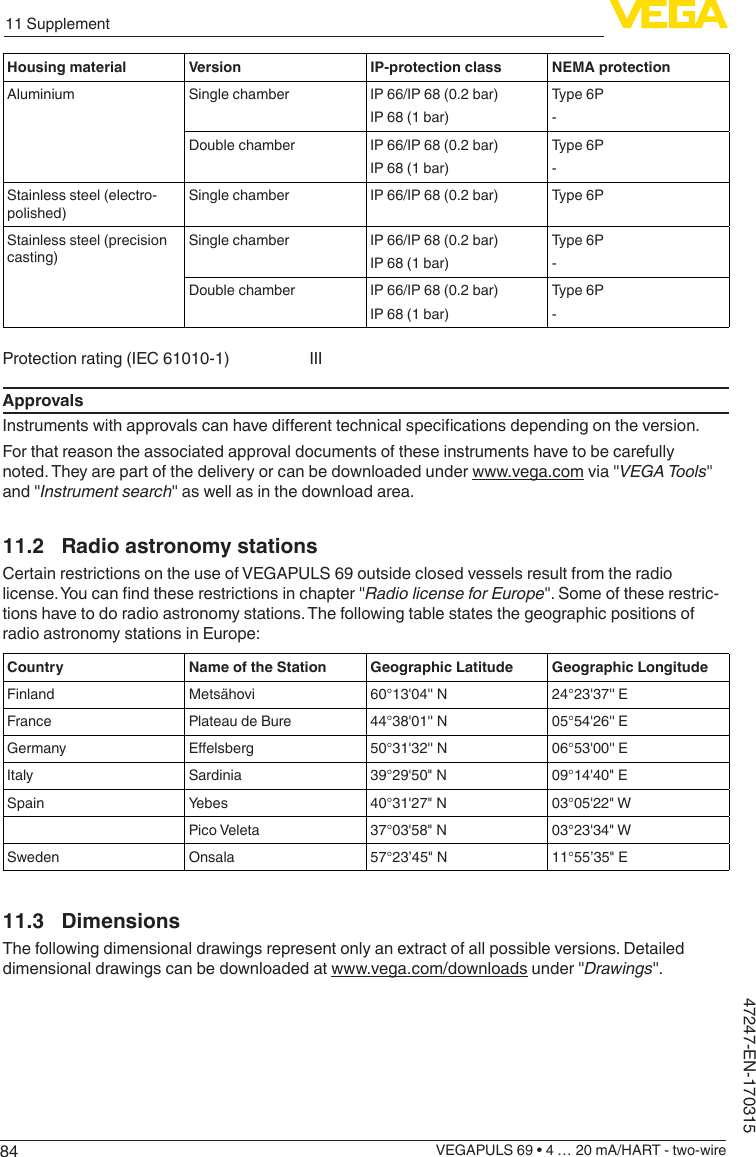
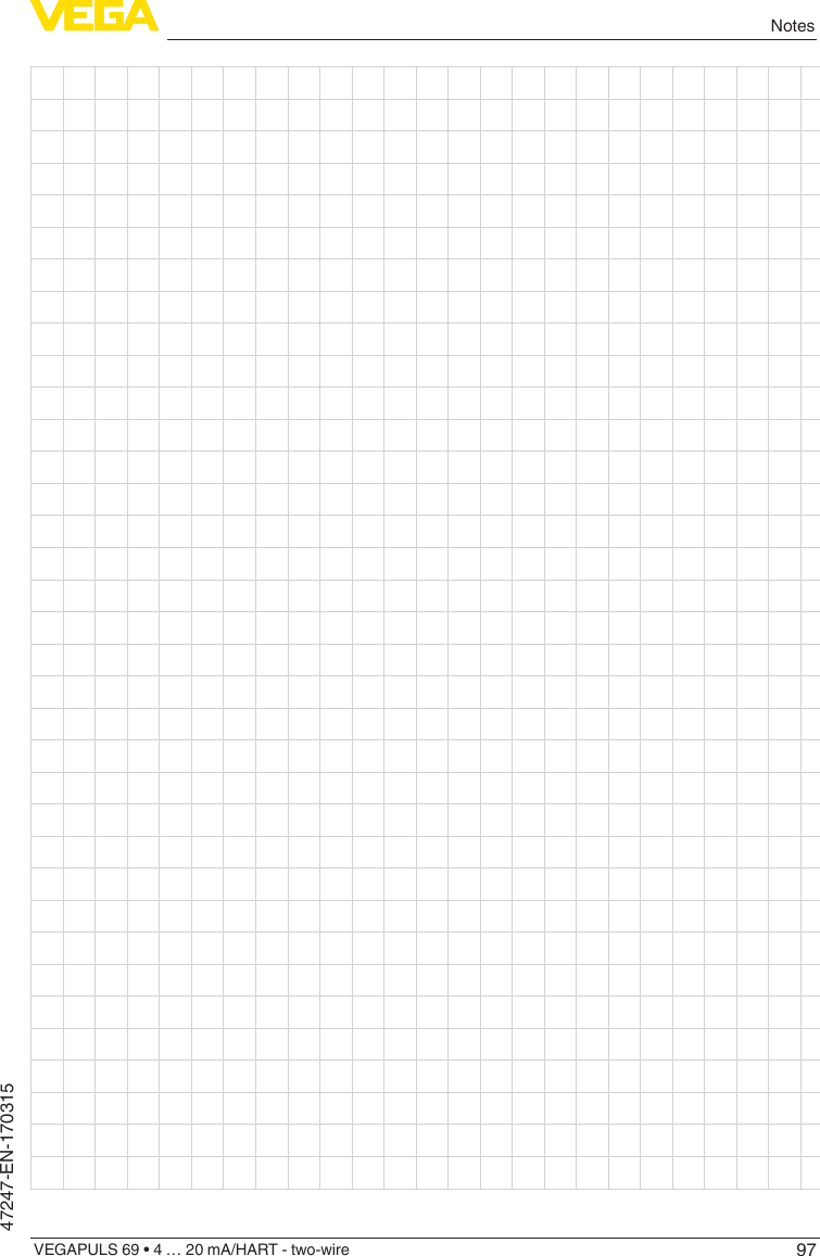
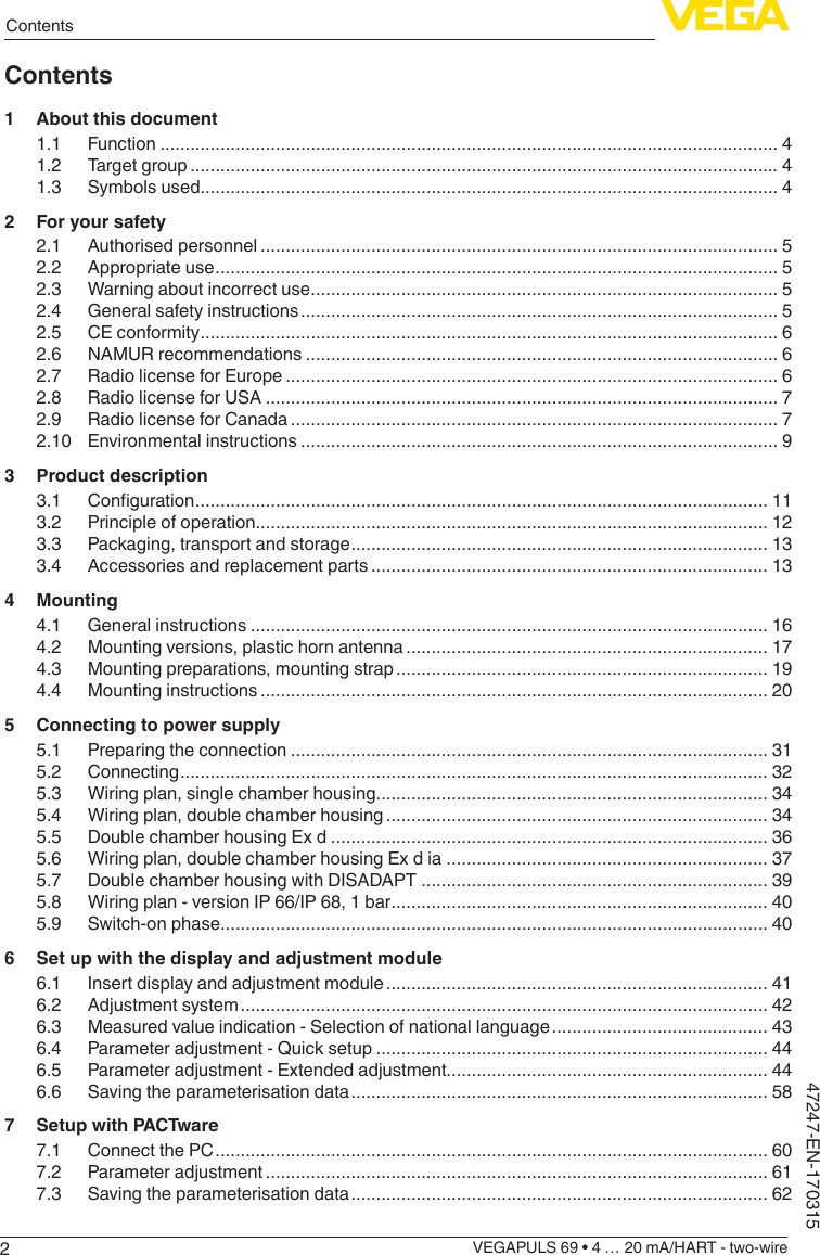
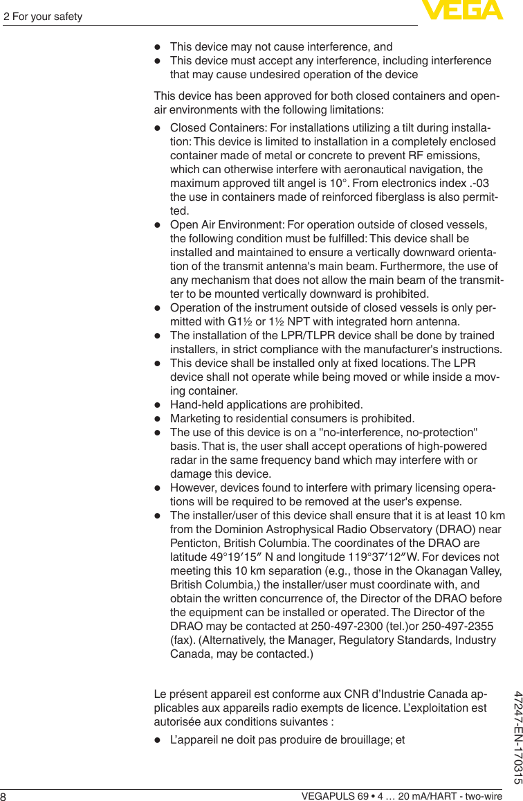
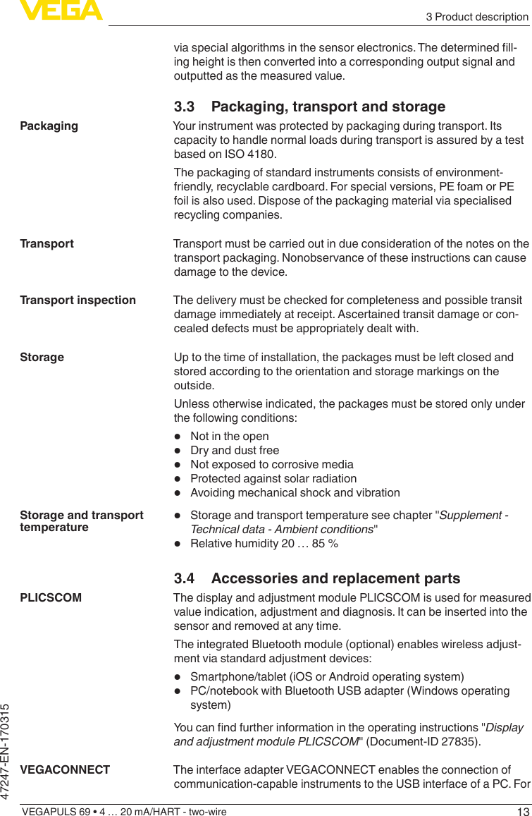
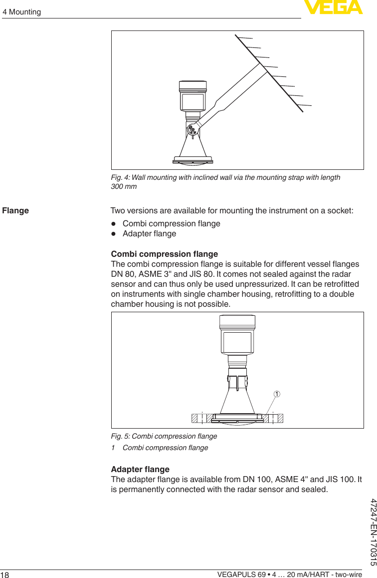
![486 Set up with the display and adjustment moduleVEGAPULS 69 • 4 … 20 mA/HART - two-wire47247-EN-170315213100%0%1 m(39.37")35 m(1378")Fig.43:Parameteradjustmentexamplemin./max.adjustment1 Min. level = max. measuring distance2 Max. level = min. measuring distance3 Reference planeIf these values are not known, an adjustment with the distances of e.g. 10%and90%ispossible.Startingpointforthesedistancespecica-tionsisalwaysthesealingsurfaceofthethreadorange.Youcanndspecicationsonthereferenceplaneinchapter"Technicaldata". The actual level is calculated on the basis of these settings.The actual product level during this adjustment is not important, because the min./max. adjustment is always carried out without changing the product level. These settings can be made ahead of time without the instrument having to be installed.Proceed as follows:1. Select with [->]themenuitemMax.adjustmentandconrmwith[OK].2. Prepare the percentage value for editing with [OK] and set the cursor to the requested position with [->].3. Set the requested percentage value with [+] and save with [OK]. The cursor jumps now to the distance value.Setup - Max. adjustment](https://usermanual.wiki/VEGA-Grieshaber-KG/PS60XW1.Users-Manual-77-GHz-031517/User-Guide-3326540-Page-48.png)
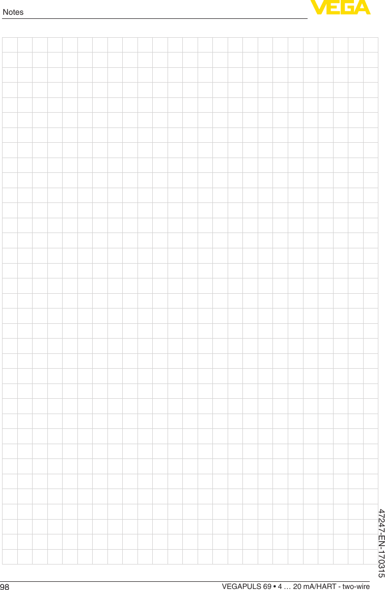
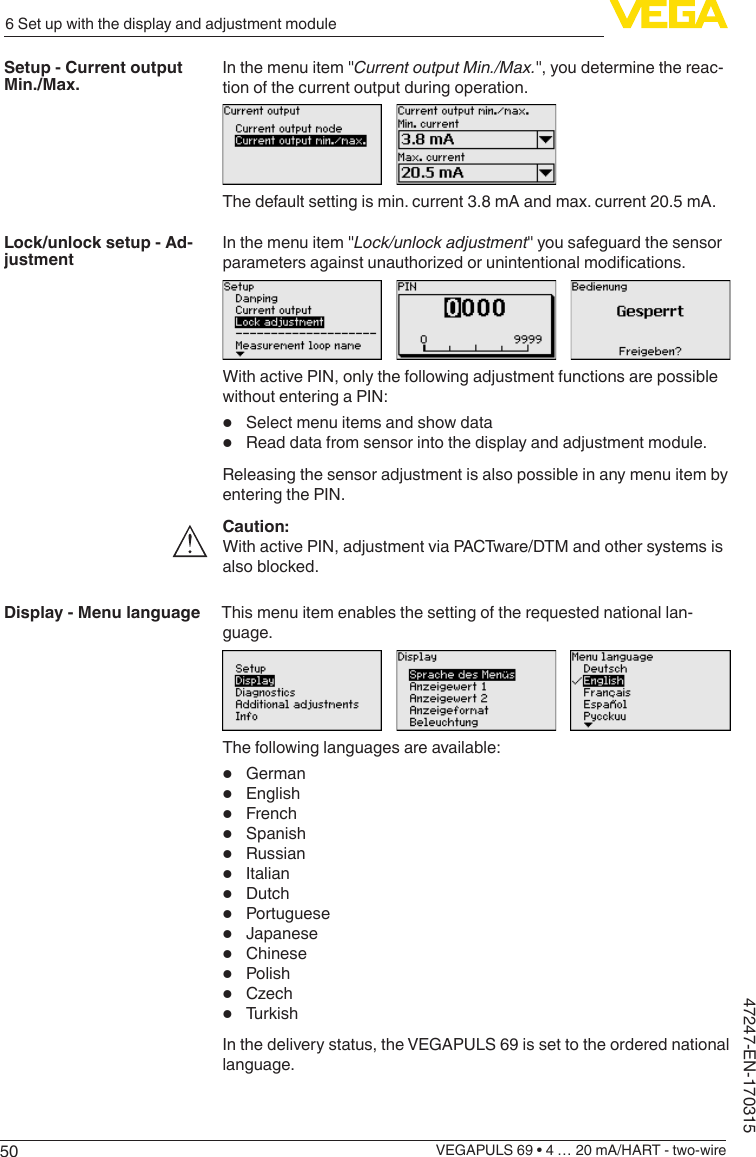
![496 Set up with the display and adjustment moduleVEGAPULS 69 • 4 … 20 mA/HART - two-wire47247-EN-1703154. For the full vessel, enter the distance value in m matching the percentage value.5. Save settings with [OK] and move with [ESC] and [->] to Min. adjustment.Proceed as follows:1. Select with [->] the menu item "Min. adjustment"andconrmwith[OK].2. Edit the percentage value with [OK] and set the cursor to the requested position with [->].3. Set the requested percentage value with [+] and save with [OK]. The cursor jumps now to the distance value.4. Enter the suitable distance value in m for the empty vessel (e.g. distance from the sensor to the vessel bottom) corresponding to the percentage value.Todampprocess-dependentmeasuredvalueuctuations,setanintegration time of 0 … 999 s in this menu item.The default setting is a damping of 0 s.In the menu item "Currentoutputmode" you determine the output characteristics and reaction of the current output in case of failure.The default setting is output characteristics 4 … 20 mA, fault mode < 3.6 mA.Setup - Min. adjustmentSetup - DampingSetup - Current output, mode](https://usermanual.wiki/VEGA-Grieshaber-KG/PS60XW1.Users-Manual-77-GHz-031517/User-Guide-3326540-Page-49.png)
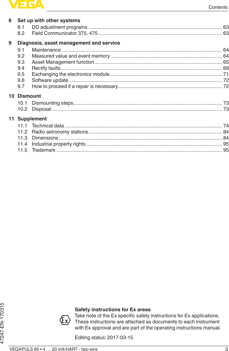
![516 Set up with the display and adjustment moduleVEGAPULS 69 • 4 … 20 mA/HART - two-wire47247-EN-170315Inthismenuitemyoucandenethewaymeasuredvaluesareindi-cated on the display.The default setting for the display value is "Percent".The display and adjustment module has a backlight for the display. In thismenuitemyoucanswitchthelightingonoro.Youcanndtherequired operating voltage in chapter "Technicaldata".In delivery status, the lighting is switched on.In this menu item, the device status is displayed.The min. and max. measured value, the measurement certainty as well as the min. and max. electronics temperature are stored in the sensor. The values are displayed in menu item "Peak value" or "Fur-ther peak values".A reset menu is opened with the [OK] key in the respective peak value window:With the [OK] key in the reset menu, the peak values are reset to the current measured value.The "Echocurve" shows the signal strength of the echoes over the measuring range in dB. The signal strength enables an evaluation of the quality of the measurement.Theselectedcurveiscontinuouslyupdated.Asubmenuwithzoomfunctions is opened with the [OK] key:• "X-Zoom":Zoomfunctionforthemeas.distance• "Y-Zoom":1,2,5and10xsignalmagnicationin"dB"• "Unzoom":ResetthepresentationtothenominalmeasuringrangewithoutmagnicationDisplay - Displayed value 1 and 2Display - BacklightDiagnostics - Device statusDiagnosis - Peak valueDiagnoses - Curve indica-tion](https://usermanual.wiki/VEGA-Grieshaber-KG/PS60XW1.Users-Manual-77-GHz-031517/User-Guide-3326540-Page-51.png)
![526 Set up with the display and adjustment moduleVEGAPULS 69 • 4 … 20 mA/HART - two-wire47247-EN-170315In this menu item you can simulate measured values via the current output. This allows the signal path to be tested, e.g. through down-stream indicating instruments or the input card of the control system.Select the requested simulation variable and set the requested value.Caution:During simulation, the simulated value is outputted as 4 … 20 mA cur-rent value and as digital HART signal. The status message within the context of the asset management function is "Maintenance".To deactivate the simulation, you have to push the [ESC] key and conrmthemessagewith the [OK] key.Information:The sensor terminates the simulation automatically after 60 minutes.The function "Setup" allows the echo curve to be saved at the time of setup.Information:This is generally recommended, however, for use of the Asset Management functions it is absolutely necessary. Saving should be carried out with a very low level.The function "Echocurvememory" allows up to ten individual echo curves to be stored, for example to detect the measurement behav-iourofthesensorindierentoperatingconditions.With the adjustment software PACTware and the PC, the stored echo curvescanbedisplayedwithhighresolutionandusedtorecognizesignal changes over time. In addition, the echo curve saved during setup can also be displayed in the echo curve window and compared with the current echo curve.Diagnosis - SimulationDiagnostics - Echo curve memory](https://usermanual.wiki/VEGA-Grieshaber-KG/PS60XW1.Users-Manual-77-GHz-031517/User-Guide-3326540-Page-52.png)
![536 Set up with the display and adjustment moduleVEGAPULS 69 • 4 … 20 mA/HART - two-wire47247-EN-170315In this menu item, the internal clock of the sensor is set to the request-ed time and time format. At the time of shipment from factory, the instrument is set to CET (Central European Time).During a reset, the parameter settings carried out by the user are reset to the default values (see below table).Proceed as follows:1. Select with [->] under "Additional adjustments" the menu item "Reset"andconrmwith[OK].2. Conrmwith[OK] and select the requested reset function with [->]3. Conrmwith[OK], for approx. 5 s the message "Resetting" is displayed, then the selection window appears.Caution:For the duration of the reset, the set trouble signal is outputted via the current output. Within the context of the asset management function, the message "Maintenance" is outputted.The following reset functions are available:Delivery status: Restores the parameter settings at the time of ship-mentfromthefactory,incl.theorder-specicsettings.Anycreatedfalsesignalsuppression,user-programmablelinearizationcurveaswell as measured value and echo curve memory is deleted. The event andparametermodicationmemoriesremainunaected.Basic settings: Resets the parameter settings, incl. special param-eters, to the default values of the respective instrument. Any stored false signal suppression or user programmable linearisation curve, as well as the measured value memory, is deleted. Order-related settings are not taken over into the current parameters after this reset.The following table shows the scope of the reset function and the default values of the instrument:Additional settings - Date/TimeAdditional adjustments - Reset](https://usermanual.wiki/VEGA-Grieshaber-KG/PS60XW1.Users-Manual-77-GHz-031517/User-Guide-3326540-Page-53.png)
![566 Set up with the display and adjustment moduleVEGAPULS 69 • 4 … 20 mA/HART - two-wire47247-EN-170315• Agitators• Buildup or welded joints on vessel wallsNote:A false signal suppression detects, marks and saves these false signals so that they are no longer taken into account in the level measurement.This should be done with the lowest possible level so that all potential interferingreectionscanbedetected.Proceed as follows:1. Select with [->] the menu item "False signal suppression" and conrmwith[OK].2. Conrmagainwith[OK].3. Conrmagainwith[OK].4. Conrmagainwith[OK] and enter the actual distance from the sensor to the product surface.5. All interfering signals in this section are detected by the sensor andstoredafterconrmingwith[OK].Note:Check the distance to the product surface, because if an incorrect (too large) value is entered, the existing level will be saved as a false signal. The level would then no longer be detectable in this area.If a false signal suppression has already been saved in the sensor, the following menu window appears when selecting "False signal suppression":](https://usermanual.wiki/VEGA-Grieshaber-KG/PS60XW1.Users-Manual-77-GHz-031517/User-Guide-3326540-Page-56.png)