VEGA Grieshaber KG PS60XW1 VEGAPULS 69 Level Probing Radar User Manual Rev 3
VEGA Grieshaber KG VEGAPULS 69 Level Probing Radar Users Manual Rev 3
Contents
- 1. Users Manual Rev 3
- 2. Users Manual 77 GHz 031517
Users Manual Rev 3
Operating Instructions
Radar sensor for continuous level
measurement of bulk solids
VEGAPULS 69
4 … 20 mA/HART - two-wire
Document ID: 47247

2
Contents
VEGAPULS 69 • 4 … 20 mA/HART - two-wire
47247-EN-150615
Contents
1 About this document
1.1 Function ........................................................................................................................... 4
1.2 Target group ..................................................................................................................... 4
1.3 Symbols used................................................................................................................... 4
2 For your safety
2.1 Authorised personnel ....................................................................................................... 5
2.2 Appropriate use ................................................................................................................ 5
2.3 Warning about incorrect use ............................................................................................. 5
2.4 General safety instructions ............................................................................................... 5
2.5 CE conformity ................................................................................................................... 6
2.6 NAMUR recommendations .............................................................................................. 6
2.7 Radio license for Europe .................................................................................................. 6
2.8 Radio License for USA ..................................................................................................... 6
2.9 Radio license for Canada ................................................................................................. 7
2.10 Environmental instructions ............................................................................................... 8
3 Product description
3.1 Conguration .................................................................................................................... 9
3.2 Principle of operation...................................................................................................... 10
3.3 Packaging, transport and storage ................................................................................... 11
3.4 Accessories and replacement parts ............................................................................... 11
4 Mounting
4.1 General instructions ....................................................................................................... 14
4.2 Mounting versions, plastic horn antenna ........................................................................ 14
4.3 Mounting preparations, mounting strap .......................................................................... 17
4.4 Mounting instructions ..................................................................................................... 18
5 Connecting to power supply
5.1 Preparing the connection ............................................................................................... 29
5.2 Connecting ..................................................................................................................... 30
5.3 Wiring plan, single chamber housing.............................................................................. 31
5.4 Wiring plan, double chamber housing ............................................................................ 32
5.5 Double chamber housing Ex d ....................................................................................... 34
5.6 Wiring plan, double chamber housing Ex d ia ................................................................ 35
5.7 Double chamber housing with DIS-ADAPT .................................................................... 37
5.8 Wiring plan - version IP 66/IP 68, 1 bar ........................................................................... 38
5.9 Switch-on phase............................................................................................................. 38
6 Set up with the display and adjustment module
6.1 Insert display and adjustment module ............................................................................ 39
6.2 Adjustment system ......................................................................................................... 40
6.3 Measured value indication - Selection national language ............................................... 41
6.4 Parameter adjustment - Quick setup .............................................................................. 42
6.5 Parameter adjustment - Extended adjustment................................................................ 43
6.6 Saving the parameter adjustment data ........................................................................... 57
7 Setup with PACTware
7.1 Connect the PC .............................................................................................................. 59
7.2 Parameter adjustment .................................................................................................... 60
7.3 Saving the parameter adjustment data ........................................................................... 61

3
Contents
VEGAPULS 69 • 4 … 20 mA/HART - two-wire
47247-EN-150615
8 Set up with other systems
8.1 DD adjustment programs ............................................................................................... 62
8.2 Field Communicator 375, 475 ........................................................................................ 62
9 Diagnosis, asset management and service
9.1 Maintenance .................................................................................................................. 63
9.2 Measured value and event memory ............................................................................... 63
9.3 Asset Management function ........................................................................................... 64
9.4 Rectify faults ................................................................................................................... 68
9.5 Exchanging the electronics module ................................................................................ 71
9.6 Software update ............................................................................................................. 72
9.7 How to proceed if a repair is necessary .......................................................................... 72
10 Dismount
10.1 Dismounting steps.......................................................................................................... 73
10.2 Disposal ......................................................................................................................... 73
11 Supplement
11.1 Technical data ................................................................................................................ 74
11.2 Radio astronomy stations ............................................................................................... 83
11.3 Dimensions .................................................................................................................... 83
Safety instructions for Ex areas
TakenoteoftheExspecicsafetyinstructionsforExapplications.
These instructions are attached as documents to each instrument
with Ex approval and are part of the operating instructions manual.
Editing status:2015-01-28
4
1 About this document
VEGAPULS 69 • 4 … 20 mA/HART - two-wire
47247-EN-150615
1 About this document
1.1 Function
This operating instructions manual provides all the information you
need for mounting, connection and setup as well as important instruc-
tionsformaintenanceandfaultrectication.Pleasereadthisinforma-
tion before putting the instrument into operation and keep this manual
accessible in the immediate vicinity of the device.
1.2 Target group
This operating instructions manual is directed to trained specialist
personnel. The contents of this manual should be made available to
these personnel and put into practice by them.
1.3 Symbols used
Information, tip, note
This symbol indicates helpful additional information.
Caution: If this warning is ignored, faults or malfunctions can result.
Warning: If this warning is ignored, injury to persons and/or serious
damage to the instrument can result.
Danger: If this warning is ignored, serious injury to persons and/or
destruction of the instrument can result.
Ex applications
This symbol indicates special instructions for Ex applications.
• List
The dot set in front indicates a list with no implied sequence.
→ Action
This arrow indicates a single action.
1 Sequence of actions
Numbers set in front indicate successive steps in a procedure.
Battery disposal
This symbol indicates special information about the disposal of bat-
teries and accumulators.

5
2 For your safety
VEGAPULS 69 • 4 … 20 mA/HART - two-wire
47247-EN-150615
2 For your safety
2.1 Authorised personnel
All operations described in this operating instructions manual must
be carried out only by trained specialist personnel authorised by the
plant operator.
During work on and with the device the required personal protective
equipment must always be worn.
2.2 Appropriate use
VEGAPULS 69 is a sensor for continuous level measurement.
Youcannddetailedinformationabouttheareaofapplicationin
chapter "Product description".
Operational reliability is ensured only if the instrument is properly
usedaccordingtothespecicationsintheoperatinginstructions
manual as well as possible supplementary instructions.
2.3 Warning about incorrect use
Inappropriate or incorrect use of the instrument can give rise to
application-specichazards,e.g.vesseloverllordamagetosystem
components through incorrect mounting or adjustment.
2.4 General safety instructions
This is a state-of-the-art instrument complying with all prevailing
regulations and guidelines. The instrument must only be operated in a
technicallyawlessandreliablecondition.Theoperatorisresponsible
for the trouble-free operation of the instrument.
During the entire duration of use, the user is obliged to determine the
compliance of the necessary occupational safety measures with the
current valid rules and regulations and also take note of new regula-
tions.
The safety instructions in this operating instructions manual, the na-
tional installation standards as well as the valid safety regulations and
accident prevention rules must be observed by the user.
For safety and warranty reasons, any invasive work on the device
beyond that described in the operating instructions manual may be
carried out only by personnel authorised by the manufacturer. Arbi-
traryconversionsormodicationsareexplicitlyforbidden.
The safety approval markings and safety tips on the device must also
be observed.
Depending on the instrument version, the emitting frequencies are in
the C, K or W band range. The low emitting frequencies are far below
the internationally approved limit values. When used correctly, the
device poses no danger to health.

6
2 For your safety
VEGAPULS 69 • 4 … 20 mA/HART - two-wire
47247-EN-150615
2.5 CE conformity
ThedevicefulllsthelegalrequirementsoftheapplicableECguide-
lines.ByaxingtheCEmarking,weconrmsuccessfultestingofthe
product.
YoucanndtheCECerticateofConformityinthedownloadsection
of our homepage.
2.6 NAMUR recommendations
NAMUR is the automation technology user association in the process
industry in Germany. The published NAMUR recommendations are
acceptedasthestandardineldinstrumentation.
ThedevicefulllstherequirementsofthefollowingNAMURrecom-
mendations:
• NE 21 – Electromagnetic compatibility of equipment
• NE 43 – Signal level for malfunction information from measuring
transducers
• NE53–Compatibilityofelddevicesanddisplay/adjustment
components
• NE107–Self-monitoringanddiagnosisofelddevices
For further information see www.namur.de.
2.7 Radio license for Europe
The instrument meets the LPR (Level Probing Radar) radio standard
EN 302729-1/2.
It is approved for unrestricted use inside and outside of closed ves-
sels in countries of the EU and EFTA that have implemented this
standard.
For operation outside of closed vessels, the following conditions must
befullled:
• Theinstallationmustbecarriedoutbytrainedqualiedpersonnel
• The instrument must be stationary mounted and the antenna
directed vertically downward
• The mounting location must be at least 4 km away from radio
astronomy stations, unless special permission was granted by the
responsible national approval authority
• When installed within 4 to 40 km of a radio astronomy station,
the instrument must not be mounted higher than 15 m above the
ground.
Youcanndalistoftherespectiveradioastronomystationsinchap-
ter "Supplement".
2.8 Radio License for USA
This device complies with Part 15 of the FCC Rules. Operation is
subject to the following two conditions:
• This device may not cause interference, and
• This device must accept any interference, including interference
that may cause undesired operation of the device

7
2 For your safety
VEGAPULS 69 • 4 … 20 mA/HART - two-wire
47247-EN-150615
This device is approved for unrestricted use only inside closed, sta-
tionary vessels made of metal or concrete.
For operation outside of closed vessels, the following conditions must
befullled:
• This device shall be installed and maintained to ensure a verti-
cally downward orientation of the transmit antenna's main beam.
Furthermore, the use of any mechanism that does not allow the
main beam of the transmitter to be mounted vertically downward is
prohibited.
• Thisdeviceshallbeinstalledonlyatxedlocations.TheLPR
device shall not operate while being moved or while inside a mov-
ing container.
• Hand-held applications are prohibited.
• Marketing to residential consumers is prohibited.
Changesormodicationsnotexpresslyapprovedbythemanufac-
turer could void the user’s authority to operate this equipment.
2.9 Radio license for Canada
This device complies with Industry Canada license-exempt RSS
standard(s). Operation is subject to the following conditions:
• This device may not cause interference, and
• This device must accept any interference, including interference
that may cause undesired operation of the device
• Installation of LPR device shall be done by trained installers, in
strict compliance with the manufacturer’s instructions
• The use of this device is on a “no-interference, no-protection”
basis. That is, the user shall accept operations of high-powered
radar in the same frequency band which may interfere with or
damage this device. However, level probing devices found to
interfere with primary licensing operations will be required to be
removed at the user’s expense
• This device shall be installed and maintained to ensure a vertically
downward orientation of the transmit antenna´s main beam
• Thisdeviceshallbeinstalledonlyatxedlocations.TheLPR
device shall not operate while beeing moved or while inside a
moving container
Le présent appareil est conforme aux CNR d'Industrie Canada ap-
plicables aux appareils radio exempts de licence. L'exploitation est
autorisée aux deux conditions suivantes:
• L'appareil ne doit pas produire de brouillage , et
• L'utilisateur de l'appareil doit accepter tout brouillage radioélect-
rique subi, même si le brouillage est susceptible d'en compromet-
tre le fonctionnement
• L'installation de l'appareil LPR doit être faite par des installateurs
expérimentés dans le respect des instructions du fabricant
• Cet appareil s'utilise en "non-interférence, non-protection". Ceci
veut dire que l'utilisateur accepte le fonctionnement de radars de
haute puissance agissant dans la même bande de fréquence et
pouvant interférer avec cet appareil ou l'endommager. Toutefois,

8
2 For your safety
VEGAPULS 69 • 4 … 20 mA/HART - two-wire
47247-EN-150615
les appareils de test de niveau qui interfèrent avec les opérations
primaires de prise de licence devront être retirés aux frais de
l'utilisateur.
• Cet appareil doit être installé et entretenu de manière à assurer
une orientation verticale vers le bas du faisceau principal de
l'antenne de transmission
• Cetappareilnedoitêtreinstalléqu'àdesemplacementsxes.
L'appareil LPR ne doit pas fonctionner pendant qu'il se déplace ou
se trouve dans un conteneur en mouvement
2.10 Environmental instructions
Protection of the environment is one of our most important duties.
That is why we have introduced an environment management system
with the goal of continuously improving company environmental pro-
tection.Theenvironmentmanagementsystemiscertiedaccording
to DIN EN ISO 14001.
Pleasehelpusfulllthisobligationbyobservingtheenvironmental
instructions in this manual:
• Chapter "Packaging, transport and storage"
• Chapter "Disposal"
9
3 Product description
VEGAPULS 69 • 4 … 20 mA/HART - two-wire
47247-EN-150615
3 Product description
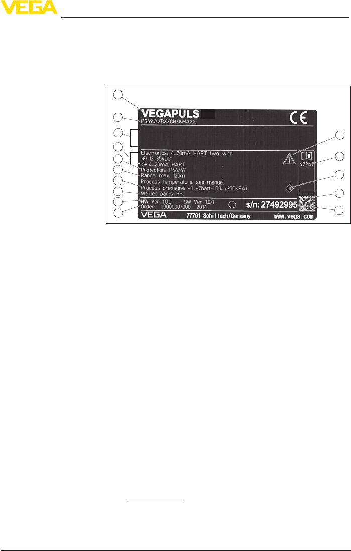
3.1 Conguration
Thetypelabelcontainsthemostimportantdataforidenticationand
use of the instrument:
2
1
14
15
13
12
11
5
6
4
3
7
8
9
10
Fig. 1: Layout of the type label (example)
1 Instrument type
2 Product code
3 Approvals
4 Power supply and signal output, electronics
5 Protection rating
6 Measuring range
7 Process and ambient temperature, process pressure
8 Material, wetted parts
9 Hardware and software version
10 Order number
11 Serial number of the instrument
12 Data-Matrix-Code for smartphone app
13 Symbol of the device protection class
14 ID numbers, instrument documentation
15 Reminder to observe the instrument documentation
16 NotiedauthorityforCEmarking
17 Approval directive
The type label contains the serial number of the instrument. With it
youcanndthefollowinginstrumentdataonourhomepage:
• Product code (HTML)
• Delivery date (HTML)
• Order-specicinstrumentfeatures(HTML)
• Operating instructions and quick setup guide at the time of ship-
ment (PDF)
• Order-specicsensordataforanelectronicsexchange(XML)
• Testcerticate(PDF)-optional
Go to www.vega.com, "VEGATools" and "Instrument search". Enter
the serial number.
Alternatively, you can access the data via your smartphone:
Type label
Serial number - Instru-
ment search

10
3 Product description
VEGAPULS 69 • 4 … 20 mA/HART - two-wire
47247-EN-150615
• Download the smartphone app "VEGATools" from the "Apple App
Store" or the "GooglePlayStore"
• Scan the Data Matrix code on the type label of the instrument or
• Enter the serial number manually in the app
This operating instructions manual applies to the following instrument
versions:
• Hardware version from 1.0.0
• Software version from 1.0.1
The scope of delivery encompasses:
• Radar sensor
• Hexagon socket wrench (for instruments with swivel holder)
• Documentation
– Quick setup guide VEGAPULS 69
– Instructions for optional instrument features
– Ex-specic"Safety instructions" (with Ex versions)
– ifnecessary,furthercerticates
• DVD "Software & Documents", containing
– Operating instructions
– Safety instructions
– PACTware/DTM Collection
– Driver software
Information:
In this operating instructions manual, the optional instrument features
are described. The respective scope of delivery results from the order
specication.
3.2 Principle of operation
The VEGAPULS 69 is a radar sensor for continuous level measure-
mentofbulksolidsevenunderthemostdicultprocessconditions
and in very large measuring ranges.
Itisidealforuseinhigh,slendersiloswithpoorlyreectingbulksolids
suchasy-ash,plasticgranulesorwoodchipsaswellasinternal
installations that cause strong false echoes. This is made possible by
its functional principle, a distance measurement through frequency
shifting with an especially small beam angle.
Theinstrumentisavailablewithdierentantennasystemsandacces-
sories for virtually all applications and processes:
• Plastic horn antenna or metal-jacketed lens antenna
• Optional or integrated rinsing air connection
• Swivelling holder with seal against the process
The instrument emits a continuous radar signal via its antenna. This
signal is frequency modulated with a sawtooth form. The emitted
signalisreectedbythemediumandreceivedbytheantennaasan
echo.
Scope of this operating
instructions manual
Scope of delivery
Application area
Functional principle

11
3 Product description
VEGAPULS 69 • 4 … 20 mA/HART - two-wire
47247-EN-150615
The frequency of the received signal always deviates from the actual
emittingfrequency.Thefrequencydierenceisproportionaltothe
distanceandthustothellingheight.Thisdierenceiscalculated
viaspecialalgorithmsinthesensorelectronics.Thedeterminedll-
ing height is then converted into a corresponding output signal and
outputted as the measured value.
3.3 Packaging, transport and storage
Your instrument was protected by packaging during transport. Its
capacity to handle normal loads during transport is assured by a test
based on ISO 4180.
The packaging of standard instruments consists of environment-
friendly, recyclable cardboard. For special versions, PE foam or PE
foil is also used. Dispose of the packaging material via specialised
recycling companies.
Transport must be carried out in due consideration of the notes on the
transport packaging. Nonobservance of these instructions can cause
damage to the device.
The delivery must be checked for completeness and possible transit
damage immediately at receipt. Ascertained transit damage or con-
cealed defects must be appropriately dealt with.
Up to the time of installation, the packages must be left closed and
stored according to the orientation and storage markings on the
outside.
Unless otherwise indicated, the packages must be stored only under
the following conditions:
• Not in the open
• Dry and dust free
• Not exposed to corrosive media
• Protected against solar radiation
• Avoiding mechanical shock and vibration
• Storage and transport temperature see chapter "Supplement -
Technicaldata-Ambientconditions"
• Relative humidity 20 … 85 %
3.4 Accessories and replacement parts
The display and adjustment module PLICSCOM is used for measured
value indication, adjustment and diagnosis. It can be inserted into the
sensor or the external display and adjustment unit and removed at
any time.
Youcanndfurtherinformationintheoperatinginstructions"Display
and adjustment module PLICSCOM" (Document-ID 27835).
The interface adapter VEGACONNECT enables the connection of
communication-capable instruments to the USB interface of a PC. For
Packaging
Transport
Transport inspection
Storage
Storage and transport
temperature
PLICSCOM
VEGACONNECT

12
3 Product description
VEGAPULS 69 • 4 … 20 mA/HART - two-wire
47247-EN-150615
parameter adjustment of these instruments, the adjustment software
PACTware with VEGA-DTM is required.
Youcanndfurtherinformationintheoperatinginstructions"Interface
adapterVEGACONNECT" (Document-ID 32628).
The VEGADIS 81 is an external display and adjustment unit for VEGA
plics® sensors.
For sensors with double chamber housing the interface adapter
"DISADAPT" is also required for VEGADIS 81.
Youcanndfurtherinformationintheoperatinginstructions"VE-
GADIS81" (Document-ID 43814).
The adapter "DISADAPT" is an accessory part for sensors with dou-
ble chamber housings. It enables the connection of VEGADIS 81 to
the sensor housing via an M12 x 1 plug.
Youcanndfurtherinformationinthesupplementaryinstructions
"AdapterDISADAPT" (Document-ID 45250).
VEGADIS 82 is suitable for measured value indication and adjustment
of sensors with HART protocol. It is looped into the 4 … 20 mA/HART
signal cable.
Youcanndfurtherinformationintheoperatinginstructions"VE-
GADIS82" (Document-ID 45300).
PLICSMOBILE T61 is an external GSM/GPRS radio unit for transmis-
sion of measured values and for remote parameter adjustment of
plics® sensors. Adjustment is carried out via PACTware/DTM and the
integrated USB connection.
Youcanndfurtherinformationinthesupplementaryinstructions
"PLICSMOBILET61" (Document-ID 37700).
PLICSMOBILE is an internal GSM/GPRS radio unit for transmission
of measured values and for remote parameter adjustment of plics®
sensors. Adjustment is carried out via PACTware/DTM and the inte-
grated USB connection.
Youcanndfurtherinformationinthesupplementaryinstructions
"PLICSMOBILEGSM/GPRSradiomodule" (Document-ID 36849).
The protective cover protects the sensor housing against soiling and
intense heat from solar radiation.
Youwillndadditionalinformationinthesupplementaryinstructions
manual "Protective cover" (Document-ID 34296).
Screwedangesareavailableindierentversionsaccordingtothe
following standards: DIN 2501, EN 1092-1, BS 10, ASME B 16.5,
JIS B 2210-1984, GOST 12821-80.
Youcanndadditionalinformationinthesupplementaryinstructions
manual "FlangesaccordingtoDIN-EN-ASME-JIS" (Document-ID
31088).
VEGADIS 81
DISADAPT
VEGADIS 82
PLICSMOBILE T61
PLICSMOBILE
Protective cap
Flanges

13
3 Product description
VEGAPULS 69 • 4 … 20 mA/HART - two-wire
47247-EN-150615
For mounting the instrument with plastic horn antenna to a socket,
twoangeversionsareavailable:thecombicompressionangeand
theadapterange
Youcanndadditionalinformationinchapter"Mounting" of this
operating instruction.
A mounting strap is available for mounting the instrument with plastic
horn antenna to the wall or ceiling.
Youcanndadditionalinformationinchapter"Mounting" of this
operating instruction.
Electronics module "VEGAPULS series 60" is a replacement part for
radarsensorsofVEGAPULSseries60.Adierentversionisavailable
for each type of signal output.
Youcanndfurtherinformationintheoperatinginstructions"Elec-
tronicsmoduleVEGAPULSseries60" (Document-ID 36801).
The supplementary electronics is a replacement part for sensors with
double chamber housing and 4 … 20 mA/HART - two-wire.
Youcanndfurtherinformationintheoperatinginstructions"Supple-
mentaryelectronicsfor4…20mA/HART-two-wire" (Document-ID
42764).
Flanges with plastic horn
antenna
Mounting strap with plas-
tic horn antenna
Electronics module
Supplementary electron-
ics for double chamber
housing

14
4 Mounting
VEGAPULS 69 • 4 … 20 mA/HART - two-wire
47247-EN-150615
4 Mounting
4.1 General instructions
Protect your instrument against moisture ingress through the following
measures:
• Use the recommended cable (see chapter "Connecting to power
supply")
• Tighten the cable gland
• Loop the connection cable downward in front of the cable gland
This applies particularly to:
• Outdoor mounting
• Installations in areas where high humidity is expected (e.g. through
cleaning processes)
• Installations on cooled or heated vessels
Make sure that all parts of the instrument exposed to the process are
suitable for the existing process conditions.
These are mainly:
• Active measuring component
• Processtting
• Process seal
Process conditions are particularly:
• Process pressure
• Process temperature
• Chemical properties of the medium
• Abrasionandmechanicalinuences
Youcannddetailedinformationontheprocessconditionsinchapter
"Technicaldata" as well as on the type label.
In the case of instrument housings with self-sealing NPT threads, it is
not possible to have the cable entries screwed in at the factory. The
free openings for the cable glands are therefore covered with red dust
protective caps as transport protection.
Prior to setup you have to replace these protective caps with ap-
proved cable glands or close the openings with suitable blind plugs.
The mounting position and orientation of the sensor must be in con-
formance with the restrictions set forth in Chapter "For your Safety",
"RadiolicenseforUSA" "Radio license for Canada" of this operating
instruction.
4.2 Mounting versions, plastic horn antenna
The optional mounting strap allows simple mounting of the instru-
ment on a wall, ceiling or boom. Especially with open vessels, this is a
simpleandeectivewaytoalignthesensortothesurfaceofthebulk
solid material.
The following versions are available:
Protection against mois-
ture
Suitability for the process
conditions
Protective caps
Radio conformance - only
for installations in USA
and Canada
Mounting strap
15
4 Mounting
VEGAPULS 69 • 4 … 20 mA/HART - two-wire
47247-EN-150615
• Length 300 mm
• Length 170 mm
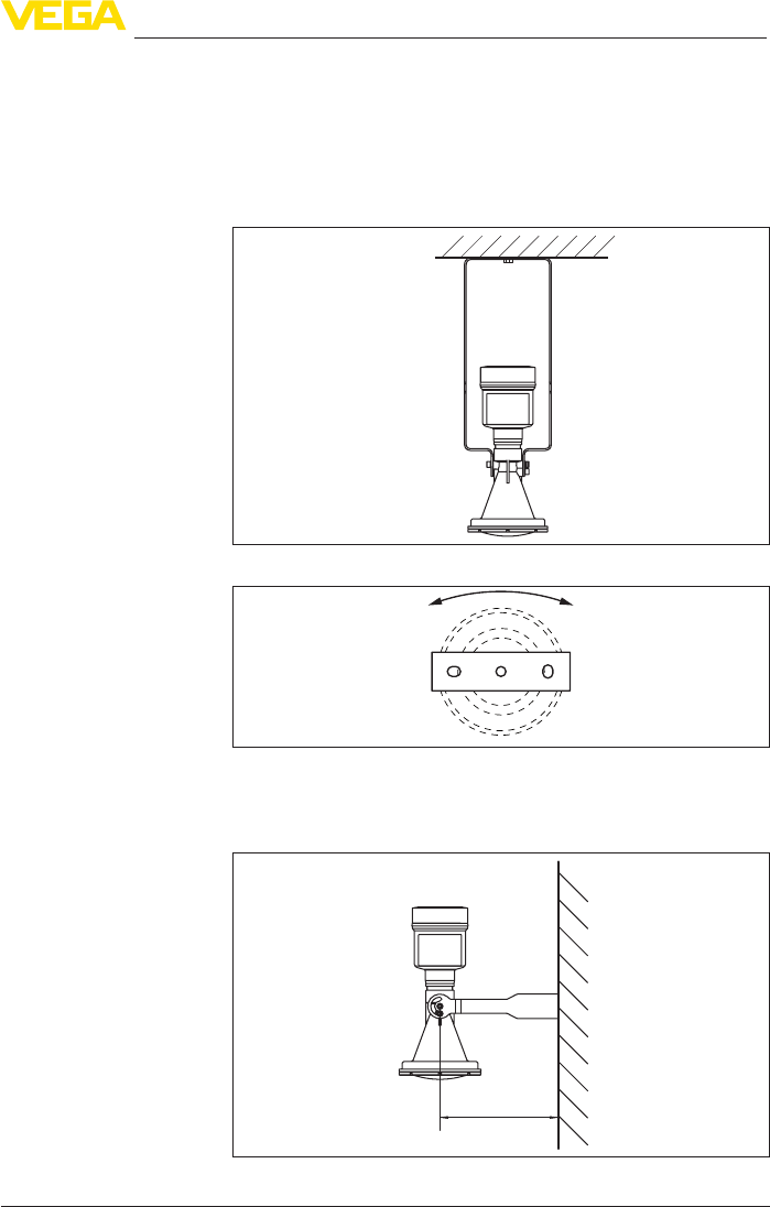
The instrument is normally mounted vertically with a bracket on the
ceiling.
This allows swivelling the sensor up to 180° for optimal orientation
and rotating for optimal connection.
Fig. 2: Ceiling mounting via the mounting strap with length 300 mm
Fig. 3: Rotating with ceil mounting
Asanalternativethestrapmountingiscarriedouthorizontallyor
obliquely.
> 200 mm
(7.87")
Fig. 4: Wall mounting horizontally via the mounting strap with length 170 mm
Mounting strap - Ceiling
mounting
Mounting strap - Wall
mounting
16
4 Mounting
VEGAPULS 69 • 4 … 20 mA/HART - two-wire
47247-EN-150615
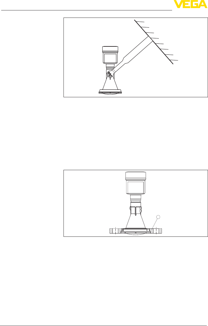
Fig. 5: Wall mounting with inclined wall via the mounting strap with length
300 mm
Two versions are available for mounting the instrument on a socket:
• CombicompressionangettingtoDN80(ASME3"andJIS80)
• AdapterangefromDN100(ASME4"orJIS100)
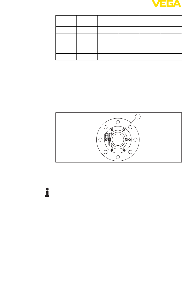
Thecombicompressionangeissuitablefordierentangestand-
ards and can be used for simple applications. It comes unassembled
and not sealed against the radar sensor and can thus only be used
unpressurized.Itcanberetrottedoninstrumentswithsinglecham-
berhousing,retrottingtoadoublechamberhousingisnotpossible.
1
Fig.6:Combicompressionange
1 Combicompressionange
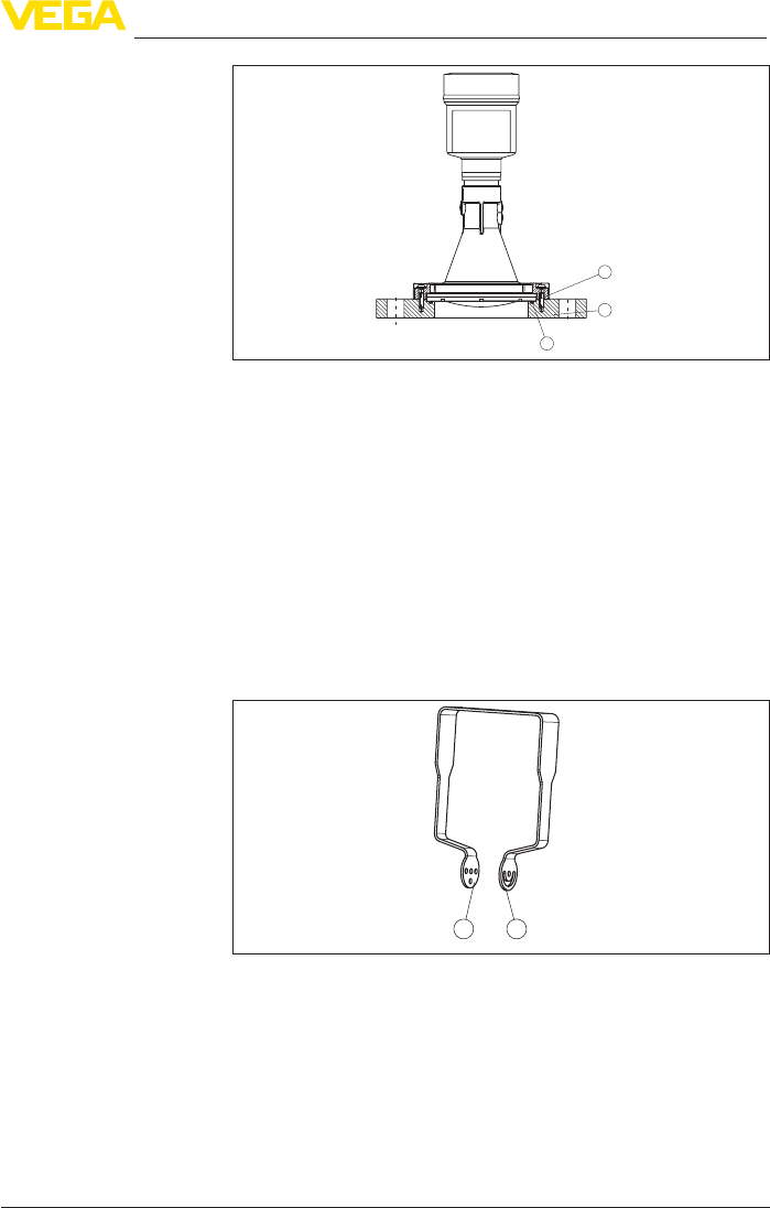
Theadapterangeisavailableindierentangesizes.Itisperma-
nently connected with the radar sensor and sealed.
Flange
17
4 Mounting
VEGAPULS 69 • 4 … 20 mA/HART - two-wire
47247-EN-150615
3
1
2
Fig.7:Adapterange
1 Connection screw
2 Adapterange
3 Process seal
Youcannddrawingsofthesemountingoptionsinchapter"Dimen-
sions".
4.3 Mounting preparations, mounting strap
The mounting strap is supplied unassembled (optionally) and must be
screwed to the sensor before setup with three hexagon socket screws
M5 x 10 and spring washers. Max. torque, see chapter "Technical
data".Requiredtools:Allenwrenchsize4.
Therearetwodierentvariantsofscrewingthestraptothesensor,
see following illustration:
1 2
Fig. 8: Mounting strap for screwing to the sensor
1 For angle of inclination in steps
2 Forangleofinclination,innitelyvariable
Depending on the selected variant, the sensor can be rotated in the
strap:
• Single chamber housing
– Angle of inclination in three steps 0°, 90° and 180°
– Angleofinclination180°,innitelyvariable
• Double chamber housing
18
4 Mounting
VEGAPULS 69 • 4 … 20 mA/HART - two-wire
47247-EN-150615
– Angleofinclination90°,innitelyvariable
– Angle of inclination in two steps 0° and 90°
4.4 Mounting instructions
Radar sensors for level measurement emit electromagnetic waves.
Thepolarizationisthedirectionoftheelectricalcomponentofthese
waves.
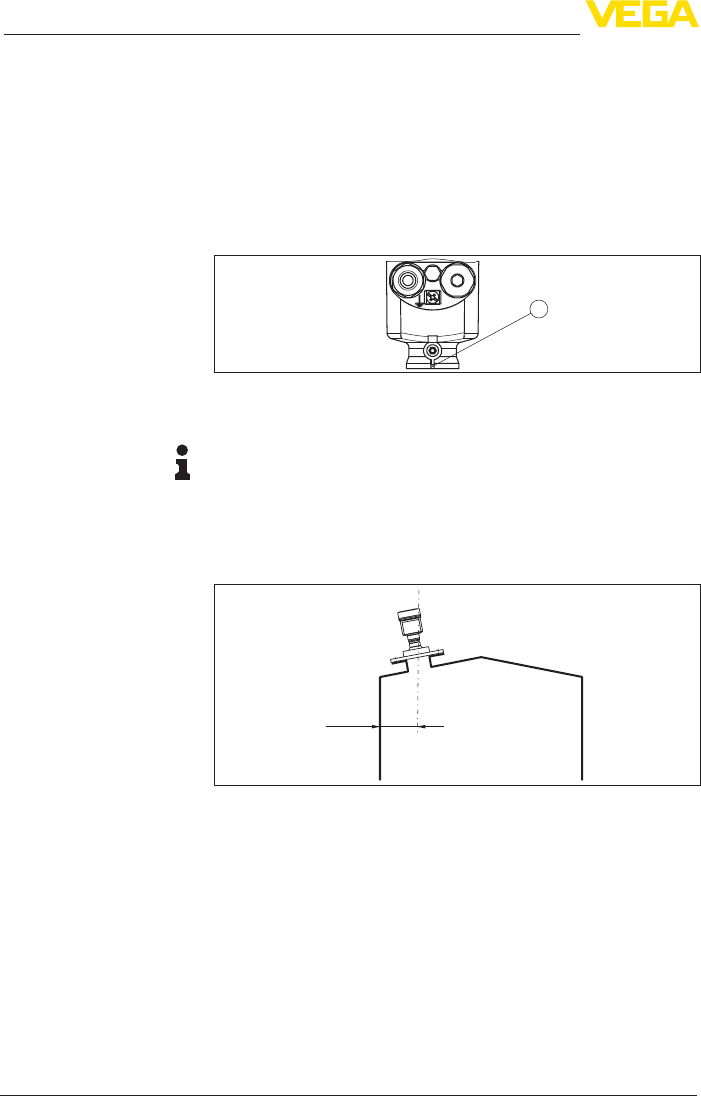
Thepolarizationdirectionismarkedbyanoseonthehousing,see
following drawing:
1
Fig. 9: Position of the polarisation
1 Nose for marking the direction of polarisation
Information:
Whenthehousingisrotated,thedirectionofpolarizationchanges
andhencetheinuenceofthefalseechoonthemeasuredvalue.
Please keep this in mind when mounting or making changes later.
Mount the sensor at least 200 mm (7.874 in) away from the vessel
wall.
200 mm
(7.87
")
Fig. 10: Mounting the radar sensor on the vessel top
If you cannot maintain this distance, you should carry out a false
signal storage during setup. This applies particularly if buildup on the
vessel wall is expected. In such cases, we recommend repeating the
false signal storage at a later date with existing buildup.
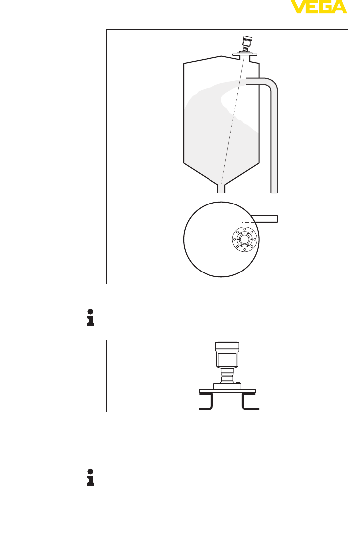
Theinstrumentshouldnotbemountedtooclosetotheinowing
medium, as the radar signal could be disrupted.
Silowithllingfromtop
Theoptimalmountingpositionisoppositethellingaperture.Toavoid
heavysoiling,thedistancetoanylterordustexhaustershouldbeas
large as possible.
Polarisation
Installation position
Inowingmedium
19
4 Mounting
VEGAPULS 69 • 4 … 20 mA/HART - two-wire
47247-EN-150615
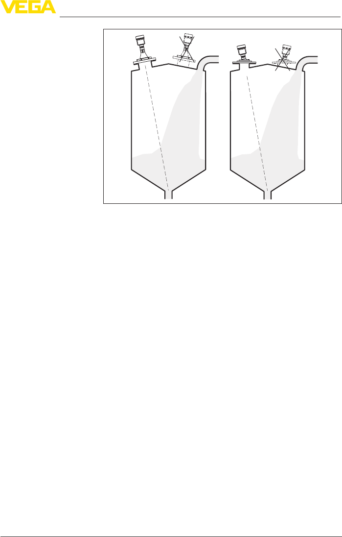
Fig.11:Mountingoftheradarsensorwithinowingmedium
Silowithlaterallling
Inbulksolidssiloswithlateralpneumaticllingtheinstrumentshould
notbemountedabovethellingstream,astheradarsignalwillbe
disrupted.Theoptimalmountingpositionisbesidethellingaperture.
Toavoidheavysoiling,thedistancetoanylterordustexhauster
should be as large as possible.
20
4 Mounting
VEGAPULS 69 • 4 … 20 mA/HART - two-wire
47247-EN-150615
Fig.12:Mountingoftheradarsensorwithinowingmedium
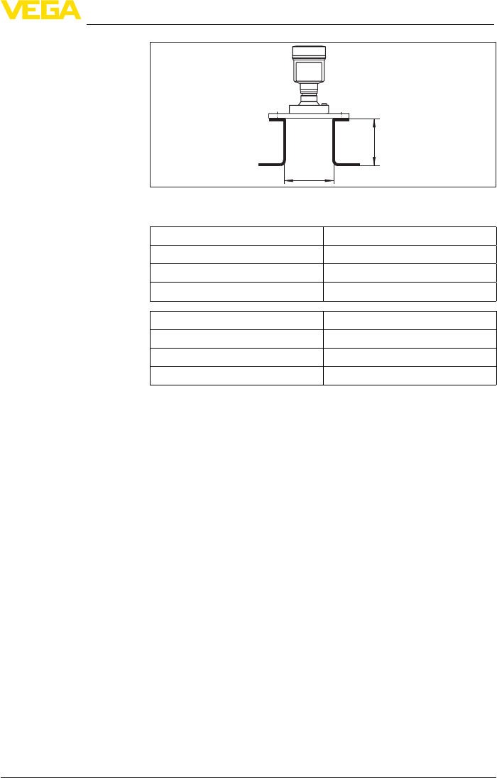
Information:
The mounting socket should be as short as possible and its end
rounded. This reduces false echoes from the vessel mounting socket.
Fig. 13: Recommended socket mounting
fthemediumhasgoodreectiveproperties,youcanalsomountthe
VEGAPULS 69 on longer sockets. Approximate socket heights are
shown in the following illustration.
Information:
When mounting on longer sockets, we recommend carrying out a
false echo storage (see chapter "Parameter adjustment").
Type of socket
21
4 Mounting
VEGAPULS 69 • 4 … 20 mA/HART - two-wire
47247-EN-150615
d
h
The below charts specify the max. pipe socket length h depending on
the diameter d.
Socket diameter d Socket length h
80 mm ≤200mm
100 mm ≤300mm
150 mm ≤500mm
Socket diameter d Socket length h
3" ≤7.87in
4" ≤11.8in
6" ≤19.7in
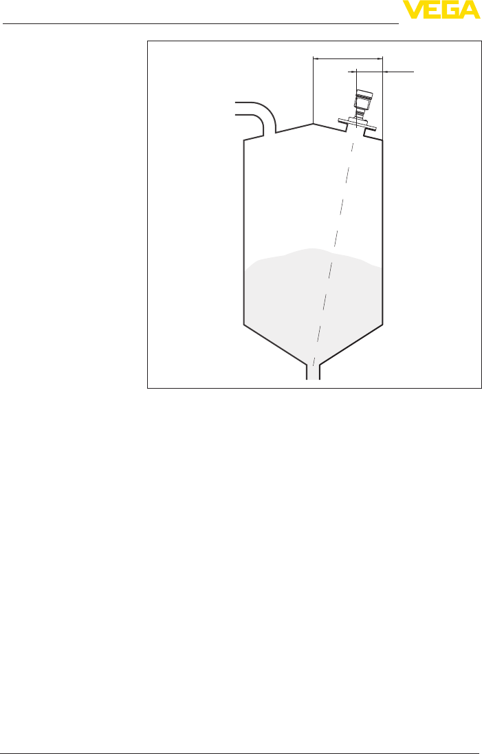
In order to measure as much of the vessel volume as possible, the
sensor should be aligned so that the radar signal reaches the lowest
level in the vessel. In a cylindrical silo with conical outlet, the sensor is
mounted anywhere from one third to one half of the vessel radius from
the outside wall (see following drawing).
Orientation
22
4 Mounting
VEGAPULS 69 • 4 … 20 mA/HART - two-wire
47247-EN-150615
r
rr...
/
13
/
12
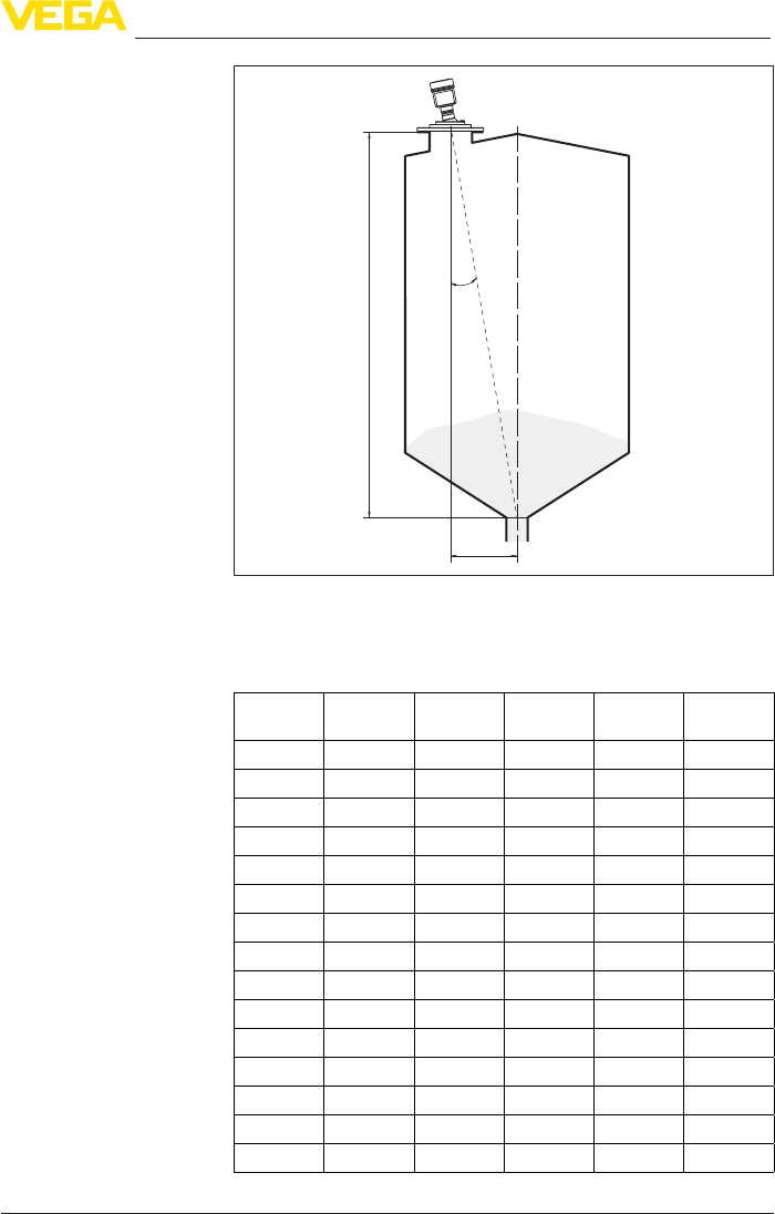
Fig. 15: Mounting position and orientation
With the help of an optional swivelling holder, the sensor can be
easily aligned to the vessel centre. The necessary angle of inclination
depends on the vessel dimensions. It can be easily checked with a
suitable bubble tube or mechanic's level on the sensor.
23
4 Mounting
VEGAPULS 69 • 4 … 20 mA/HART - two-wire
47247-EN-150615
d
a
α
Fig.16:ProposalforinstallationafterorientationVEGAPULS69
The following table shows the necessary angle of inclination. It
depends on the measuring distance and the distance "a" between
vessel centre and installation position.
Distance d
(m)
2° 4° 6° 8° 10°
2 0.1 0.1 0.2 0.3 0.4
4 0.1 0.3 0.4 0.6 0.7
6 0.2 0.4 0.6 0.8 1.1
8 0.3 0.6 0.8 1.1 1.4
10 0.3 0.7 1.1 1.4 1.8
15 0.5 1 1.6 2.1 2.6
20 0.7 1.4 2.1 2.8 3.5
25 0.9 1.7 2.6 3.5 4.4
30 1 2.1 3.2 4.2 5.3
35 1.2 2.4 3.7 4.9 6.2
40 1.4 2.8 4.2 5.6 7.1
45 1.6 3.1 4.7 6.3 7.9
50 1.7 3.5 5.3 7 8.8
60 2.1 4.2 6.3 8.4 10.5
70 2.4 4.9 7.3 9.7 12.2
24
4 Mounting
VEGAPULS 69 • 4 … 20 mA/HART - two-wire
47247-EN-150615
Distance d
(m)
2° 4° 6° 8° 10°
80 2.8 5.6 8.4 11.1 13.9
90 3.1 6.3 9.4 12.5 15.6
100 3.5 7 10.5 13.9 17.4
110 3.8 7.7 11.5 15.3 19.1
120 4.2 8.4 12.5 16.7 20.8
Example:
In a vessel 20 m high, the installation position of the sensor is 1.4 m
from the vessel centre.
The necessary angle of inclination of 4° can be read out from this
chart.
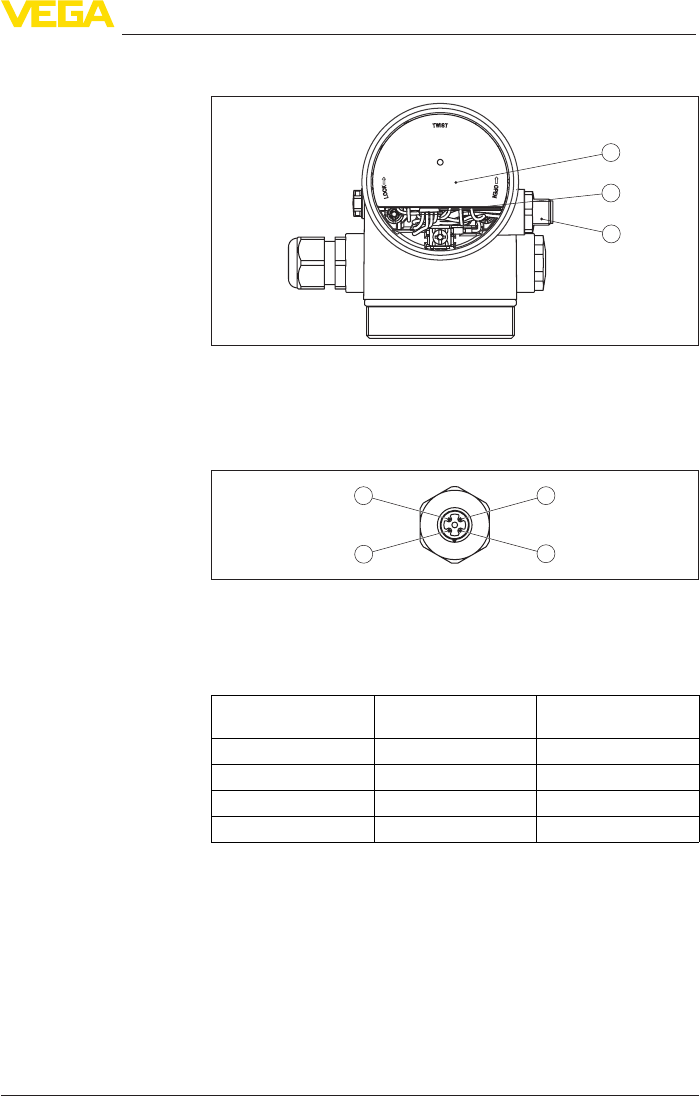
Proceed as follows to adjust the angle of inclination with the swivelling
holder:
1. Loosen the terminal screws of the swivel holder by one turn. Use
ahexagonsocketwrench,size5.
1
Fig.17:VEGAPULS69withswivellingholder
1 Terminalscrews(6pcs.)
2. Align the sensor, check angle of inclination
Information:
The max. angle of inclination of the swivelling holder is approx. 10°
3. Tighten the clamping screws, torque max. 8 Nm.
The mounting location of the radar sensor should be a place where no
otherequipmentorxturescrossthepathoftheradarsignals.
Vessel installations, such as e.g. ladders, limit switches, heating spi-
rals, struts, etc., can cause false echoes and impair the useful echo.
Make sure when planning your measuring point that the radar sensor
has a "clear view" to the measured product.
In case of existing vessel installations, a false echo storage should be
carried out during setup.
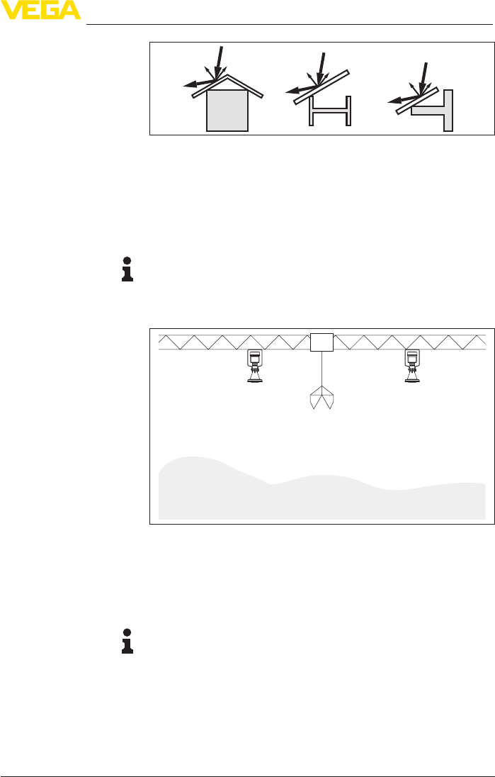
If large vessel installations such as struts or supports cause false
echoes, these can be attenuated through supplementary measures.
Small,inclinedsheetmetalbaesabovetheinstallationsscatterthe
radarsignalsandpreventdirectinterferingreections.
Vessel installations
25
4 Mounting
VEGAPULS 69 • 4 … 20 mA/HART - two-wire
47247-EN-150615
Fig.18:Coverat,large-areaproleswithdeectors
Large material heaps are best measured with several instruments,
which can be mounted on e.g. traverse cranes. For this type of ap-
plication it is advantageous to orient the sensor perpendicular to the
bulk solid surface.
Thesensorsdonotinuenceeachother.
Information:
Keep in mind that for these applications, the sensors are designed
for relatively slow level changes. If the sensor is used on a movable
boom, the max. measuring rate must be observed (see chapter
"Technicaldata").
Fig. 19: Radar sensors on traverse crane
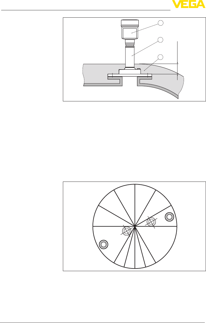
Instruments for a temperature range up to 200° C have a spacer
betweenprocessttingandelectronicshousing.Thisspacerisused
to thermally decouple the electronics from the high process tempera-
tures.
Information:
The spacer may only be incorporated up to a maximum of 50 mm into
the vessel insulation. Only then is a reliable temperature decoupling
guaranteed.
Material heaps
Mounting in the vessel
insulation
26
4 Mounting
VEGAPULS 69 • 4 … 20 mA/HART - two-wire
47247-EN-150615
max. 50 mm
(1.97")
1
2
3
Fig. 20: Mounting the instrument on insulated vessels.
1 Electronicshousing
2 Spacer
3 Vessel insulation
Thewallsofmultiple-chambersilosareoftenmadeofprolematerial,
e.g.prolesheeting,toensuretherequiredstability.Iftheradarsen-
sor is mounted very close to a heavily structured vessel wall, substan-
tialinterferingreectionscanbegenerated.Thusthesensorshould
be mounted at the largest possible distance from the separating wall.
The best mounting location is on the outer wall of the silo, with the
sensor pointing towards the discharge opening in the silo centre. This
can be accomplished, for example, with the mounting strap.
Fig. 21: Installation and orientation in multiple chamber silos
Mounting in multiple
chamber silo
27
4 Mounting
VEGAPULS 69 • 4 … 20 mA/HART - two-wire
47247-EN-150615
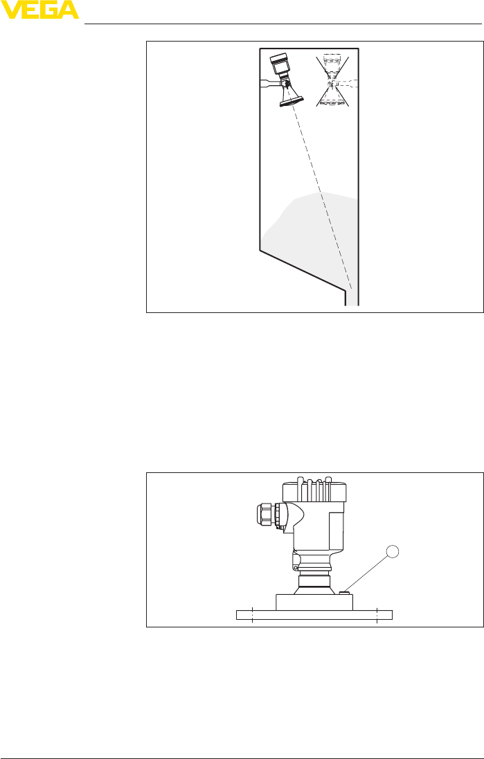
Fig. 22: Installation and orientation in multiple chamber silos
To avoid heavy buildup and dust on the antenna, the sensor should
not be mounted close to the dust exhauster inside the vessel.
To protect the sensor against buildup, particularly in case of strong
condensation, air rinsing is recommended.
Metal-jacketed lens antenna
The VEGAPULS 69 with metal-jacketed lens antenna is equipped
with a rinsing air connection as a standard feature, see following
graphics.
1
Fig. 23: Rinsing air connection on metal-jacketed lens antenna
Plastic horn antenna
The VEGAPULS 69 with plastic horn antenna is optionally available
witharinsingairconnection.Themechanicalcongurationdiers
accordingtotheangeversion,seefollowinggraphics.
Dust deposits - Rinsing
air connection
28
4 Mounting
VEGAPULS 69 • 4 … 20 mA/HART - two-wire
47247-EN-150615
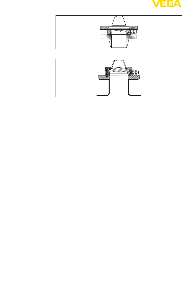
Fig.24:Rinsingairconnectionwithcompressionange
Fig.25:Rinsingairconnectionwithadapterange
Youcannddetailsontherinsingairconnectioninchapter"Technical
data".

29
5 Connecting to power supply
VEGAPULS 69 • 4 … 20 mA/HART - two-wire
47247-EN-150615
5 Connecting to power supply
5.1 Preparing the connection
Always keep in mind the following safety instructions:
Warning:
Connect only in the complete absence of line voltage.
• The electrical connection must only be carried out by trained
personnel authorised by the plant operator.
• If overvoltage surges are expected, overvoltage arresters should
be installed.
Power supply and current signal are carried on the same two-wire
cable.Theoperatingvoltagecandierdependingontheinstrument
version.
Thedataforpowersupplyarespeciedinchapter"Technicaldata".
Provide a reliable separation between the supply circuit and the
mains circuits according to DIN EN 61140 VDE 0140-1.
Keepinmindthefollowingadditionalfactorsthatinuencetheoperat-
ing voltage:
• Lower output voltage of the power supply unit under nominal load
(e.g. with a sensor current of 20.5 mA or 22 mA in case of fault)
• Inuenceofadditionalinstrumentsinthecircuit(seeloadvaluesin
chapter "Technicaldata")
The instrument is connected with standard two-wire cable without
screen. If electromagnetic interference is expected which is above the
test values of EN 61326-1 for industrial areas, screened cable should
be used.
Use cable with round cross section for instruments with housing and
cablegland.Toensurethesealeectofthecablegland(IPprotection
rating),ndoutwhichcableouterdiameterthecableglandissuitable
for.
Useacableglandttingthecablediameter.
We generally recommend the use of screened cable for HART multi-
drop mode.
With plastic housing, the NPT cable gland or the Conduit steel tube
must be screwed without grease into the threaded insert.
Max. torque for all housings see chapter "Technicaldata".
If screened cable is required, we recommend connecting the cable
screen on both ends to ground potential. In the sensor, the screen
must be connected directly to the internal ground terminal. The
ground terminal on the outside of the housing must be connected to
the ground potential (low impedance).
In Ex systems, the grounding is carried out according to the installa-
tion regulations.
Safety instructions
Voltage supply
Connection cable
Cable gland ½ NPT
Cable screening and
grounding
30
5 Connecting to power supply
VEGAPULS 69 • 4 … 20 mA/HART - two-wire
47247-EN-150615
5.2 Connecting
The voltage supply and signal output are connected via the spring-
loaded terminals in the housing.
Connection to the display and adjustment module or to the interface
adapter is carried out via contact pins in the housing.
Information:
The terminal block is pluggable and can be removed from the
electronics. To do this, lift the terminal block with a small screwdriver
and pull it out. When reinserting the terminal block, you should hear it
snap in.
Proceed as follows:
1. Unscrew the housing lid
2. If a display and adjustment module is installed, remove it by turn-
ing it slightly to the left.
3. Loosen compression nut of the cable entry gland
4. Remove approx. 10 cm (4 in) of the cable mantle, strip approx.
1 cm (0.4 in) of insulation from the ends of the individual wires
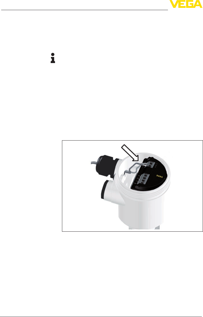
5. Insert the cable into the sensor through the cable entry
Fig. 26: Connection steps 5 and 6 - Single chamber housing
Connection technology
Connection procedure
31
5 Connecting to power supply
VEGAPULS 69 • 4 … 20 mA/HART - two-wire
47247-EN-150615
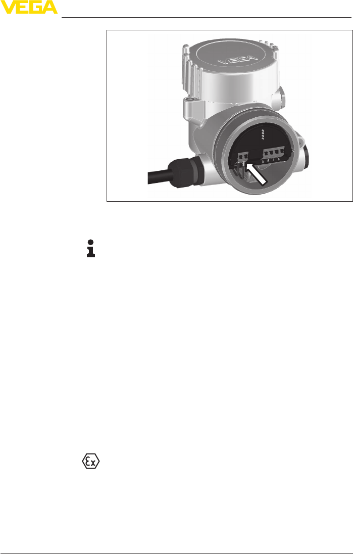
Fig. 27: Connection steps 5 and 6 - Double chamber housing
6. Insert the wire ends into the terminals according to the wiring plan
Information:
Solidcoresaswellasexiblecoreswithwireendsleevesareinsert-
eddirectlyintotheterminalopenings.Incaseofexiblecoreswithout
end sleeves, press the terminal from above with a small screwdriver,
the terminal opening is then free. When the screwdriver is released,
the terminal closes again.
Youcanndfurtherinformationonthemax.wirecross-sectionunder
"Technicaldata/Electromechanicaldata"
7. Check the hold of the wires in the terminals by lightly pulling on
them
8. Connect the screen to the internal ground terminal, connect the
outer ground terminal to potential equalisation
9. Tighten the compression nut of the cable entry gland. The seal
ring must completely encircle the cable
10. Reinsert the display and adjustment module, if one was installed
11. Screw the housing lid back on
Theelectricalconnectionisnished.
5.3 Wiring plan, single chamber housing
The following illustration applies to the non-Ex as well as to the Ex-ia
version.
32
5 Connecting to power supply
VEGAPULS 69 • 4 … 20 mA/HART - two-wire
47247-EN-150615
5
12
+
( ) (-)
678
4...20mA
2
3
4
1
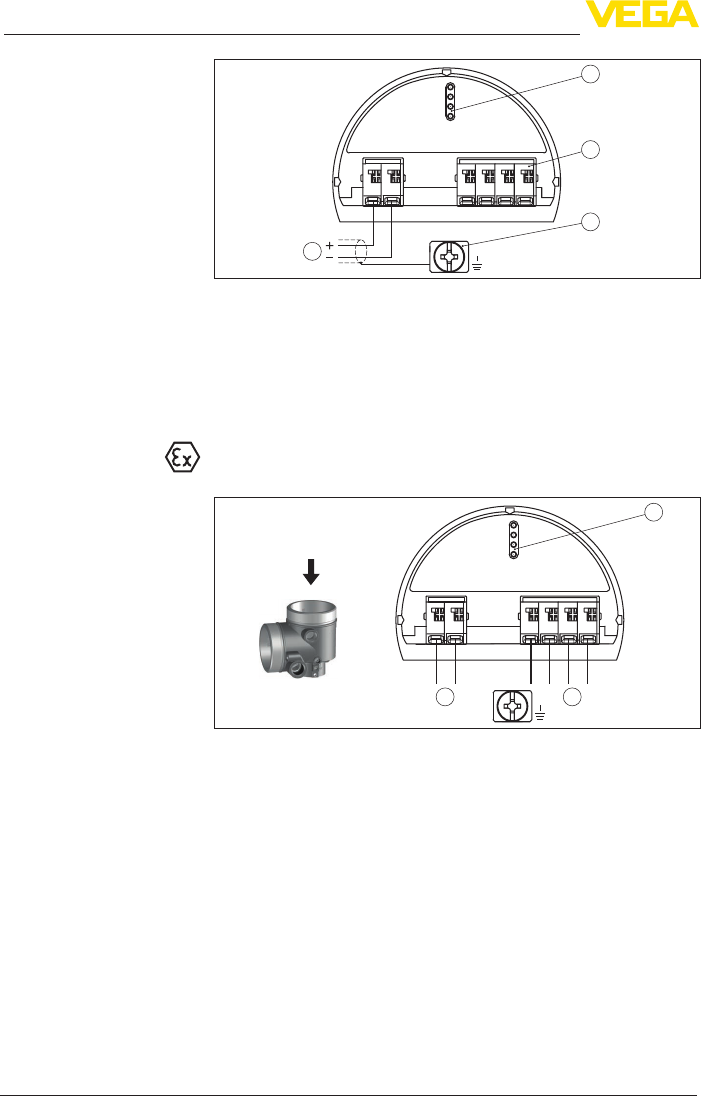
Fig.28:Electronicsandterminalcompartment,singlechamberhousing
1 Voltage supply, signal output
2 For display and adjustment module or interface adapter
3 For external display and adjustment unit
4 Groundterminalforconnectionofthecablescreen
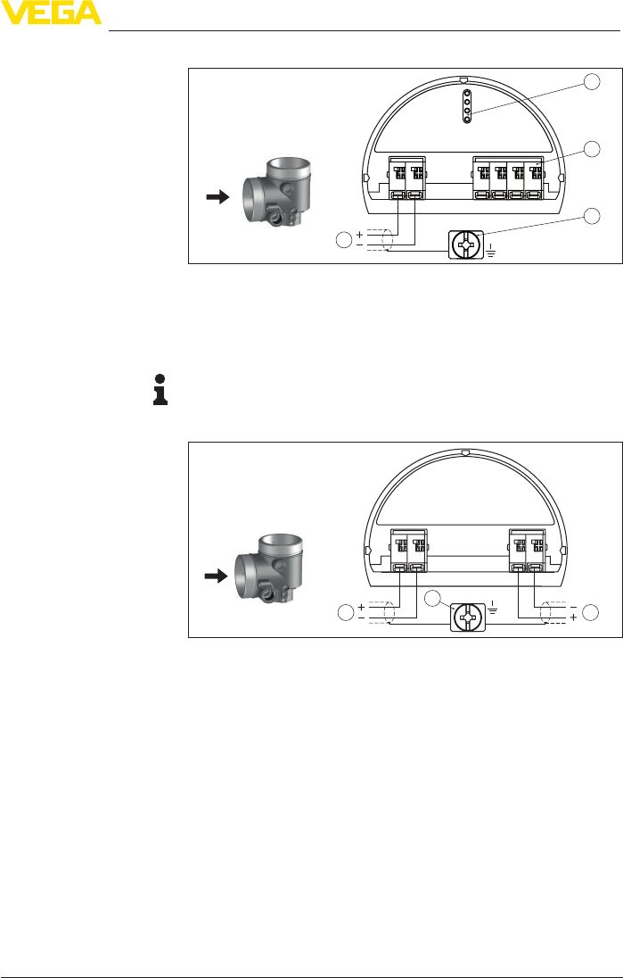
5.4 Wiring plan, double chamber housing
The following illustrations apply to the non-Ex as well as to the Ex-ia
version.
5678
4...20mA
12
+
( ) (-)
2
1 1
Fig.29:Electronicscompartment,doublechamberhousing
1 Internal connection to the terminal compartment
2 For display and adjustment module or interface adapter
Electronics and terminal
compartment
Electronics compartment
33
5 Connecting to power supply
VEGAPULS 69 • 4 … 20 mA/HART - two-wire
47247-EN-150615
5
12
+
( ) (-)
678
4...20mADisplay
2
3
4
1
Fig.30:Terminalcompartment,doublechamberhousing
1 Voltage supply, signal output
2 For display and adjustment module or interface adapter
3 For external display and adjustment unit
4 Groundterminalforconnectionofthecablescreen
Information:
Parallel use of an external display and adjustment unit and a display
and adjustment module in the terminal compartment is not supported.
12
+
( ) (-)
I
4...20mA
I I
4...20mA
78
+
( ) (-)
3
1 2
Fig.31:Terminalcompartment,doublechamberhousing,supplementaryelec-
tronics - additional current output
1 Firstcurrentoutput(I)-Voltagesupplyandsignaloutput(HART)
2 Secondcurrentoutput(II)-Voltagesupplyandsignaloutput(withoutHART)
3 Groundterminalforconnectionofthecablescreen
Terminal compartment
Connection compart-
ment - Additional current
output
34
5 Connecting to power supply
VEGAPULS 69 • 4 … 20 mA/HART - two-wire
47247-EN-150615
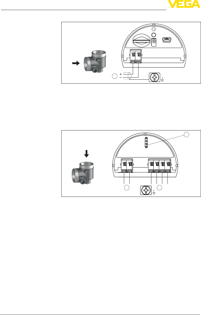
1
USB
Status
Te st
SIM-Card
12
+
( ) (-)
Fig.32:Terminalcompartment,radiomodulePLICSMOBILE
1 Voltage supply
Youcannddetailedinformationonconnectioninthesupplementary
instructions "PLICSMOBILEGSM/GPRSradiomodule".
5.5 Double chamber housing Ex d
5678
4...20mA
2
12
+
( ) (-)
11
Fig.33:Electronicscompartment,doublechamberhousingExd
1 Internal connection to the terminal compartment
2 For display and adjustment module or interface adapter
Terminal compartment
- Radio module PLICS-
MOBILE
Electronics compartment
35
5 Connecting to power supply
VEGAPULS 69 • 4 … 20 mA/HART - two-wire
47247-EN-150615
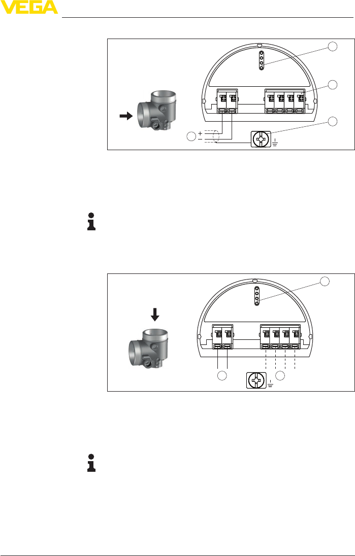
5
12
+
( ) (-)
678
4...20mA
2
3
4
1
Fig.34:Terminalcompartment,doublechamberhousing
1 Voltage supply, signal output
2 For display and adjustment module or interface adapter
3 For external display and adjustment unit
4 Groundterminalforconnectionofthecablescreen
Information:
Parallel use of an external display and adjustment unit and a display
and adjustment module in the terminal compartment is not supported.
5.6 Wiring plan, double chamber housing Ex d ia
31
2
5678
12
( ) (-)
+
4...20mA
Fig.35:Electronicscompartment,doublechamberhousingExdia
1 Internal connection to the terminal compartment
2 For display and adjustment module or interface adapter
3 Internal connection to the plug connector for external display and adjust-
ment unit (optional)
Note:
HART multidrop mode is not possible when using an Ex-d-ia instru-
ment.
Terminal compartment
Electronics compartment
36
5 Connecting to power supply
VEGAPULS 69 • 4 … 20 mA/HART - two-wire
47247-EN-150615
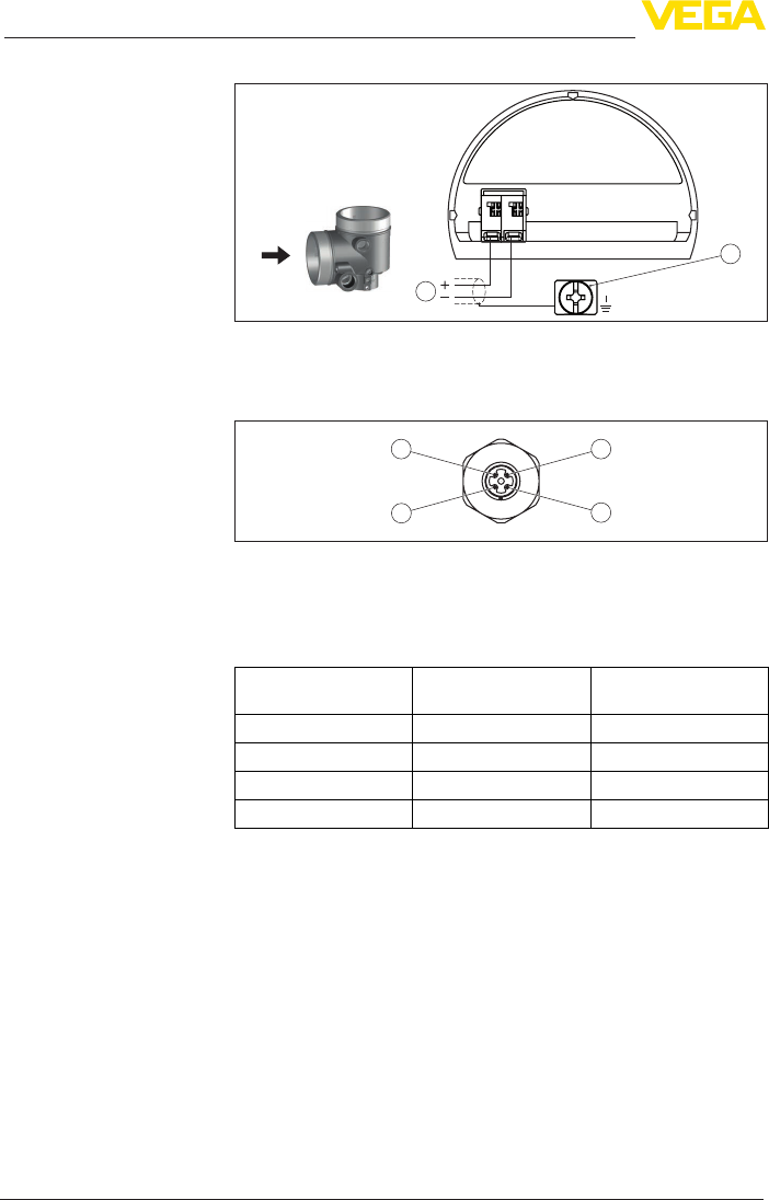
4...20mA
12
+
( ) (-)
2
1
Fig.36:Terminalcompartment,doublechamberhousingExdia
1 Voltage supply, signal output
2 Groundterminalforconnectionofthecablescreen
34
12
Fig.37:Topviewoftheplugconnector
1 Pin 1
2 Pin 2
3 Pin 3
4 Pin 4
Contact pin Colour connection ca-
ble in the sensor
Terminal, electronics
module
Pin 1 Brown 5
Pin 2 White 6
Pin 3 Blue 7
Pin 4 Black 8
Terminal compartment
Plug M12 x 1 for external
display and adjustment
unit
37
5 Connecting to power supply
VEGAPULS 69 • 4 … 20 mA/HART - two-wire
47247-EN-150615
5.7 Double chamber housing with DIS-ADAPT
3
1
2
Fig.38:ViewtotheelectronicscompartmentwithDISADAPTforconnectionof
the external display and adjustment unit
1 DISADAPT
2 Internal plug connection
3 Plug connector M12 x 1
34
12
Fig. 39: View to the plug connector M12 x 1
1 Pin 1
2 Pin 2
3 Pin 3
4 Pin 4
Contact pin Colour connection ca-
ble in the sensor
Terminal, electronics
module
Pin 1 Brown 5
Pin 2 White 6
Pin 3 Blue 7
Pin 4 Black 8
Electronics compartment
Assignment of the plug
connector
38
5 Connecting to power supply
VEGAPULS 69 • 4 … 20 mA/HART - two-wire
47247-EN-150615
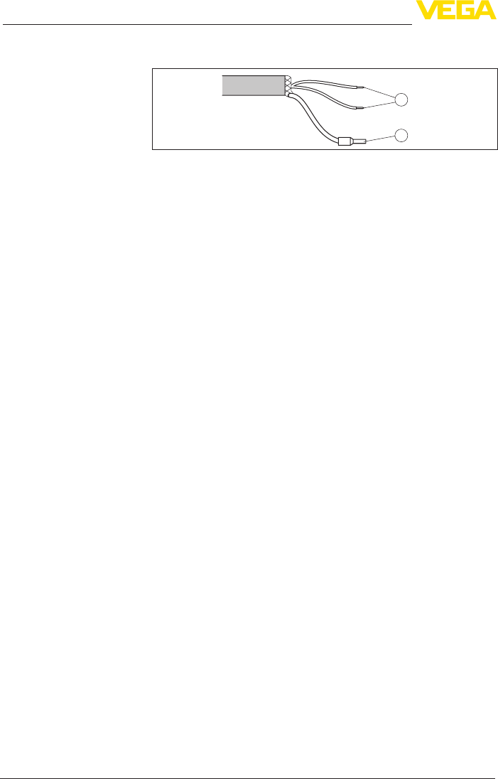
5.8 Wiring plan - version IP 66/IP 68, 1 bar
1
2
Fig. 40: Wire assignment in permanently connected connection cable
1 brown (+) and blue (-) to power supply or to the processing system
2 Shielding
5.9 Switch-on phase
After connecting the instrument to power supply or after a voltage
recurrence, the instrument carries out a self-check for approx. 30 s:
• Internal check of the electronics
• Indication of the instrument type, hardware and software version,
measurement loop name on the display or PC
• Indication of the status message "F 105 Determine measured
value" on the display or PC
• The output signal jumps to the set fault current
As soon as a plausible measured value is found, the corresponding
current is outputted to the signal cable. The value corresponds to the
actual level as well as the settings already carried out, e.g. factory
setting.
Wire assignment, con-
nection cable
39
6 Set up with the display and adjustment module
VEGAPULS 69 • 4 … 20 mA/HART - two-wire
47247-EN-150615
6 Set up with the display and adjustment
module
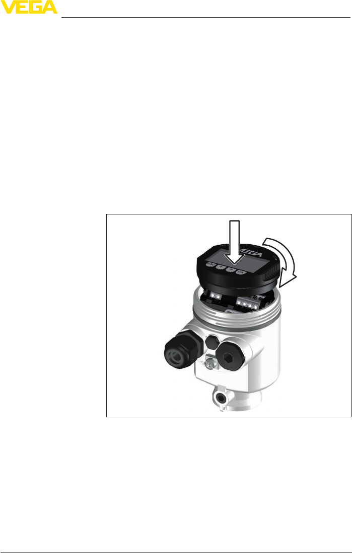
6.1 Insert display and adjustment module
The display and adjustment module can be inserted into the sensor
andremovedagainatanytime.Youcanchooseanyoneoffourdier-
ent positions - each displaced by 90°. It is not necessary to interrupt
the power supply.
Proceed as follows:
1. Unscrew the housing lid
2. Place the display and adjustment module on the electronics in the
desired position and turn it to the right until it snaps in.
3. Screw housing lid with inspection window tightly back on
Disassembly is carried out in reverse order.
The display and adjustment module is powered by the sensor, an ad-
ditional connection is not necessary.
Fig. 41: Installing the display and adjustment module in the electronics compart-
ment of the single chamber housing
40
6 Set up with the display and adjustment module
VEGAPULS 69 • 4 … 20 mA/HART - two-wire
47247-EN-150615
1 2
Fig. 42: Installing the display and adjustment module in the double chamber
housing
1 In the electronics compartment
2 In the terminal compartment
Note:
Ifyouintendtoretrottheinstrumentwithadisplayandadjustment
module for continuous measured value indication, a higher lid with an
inspection glass is required.
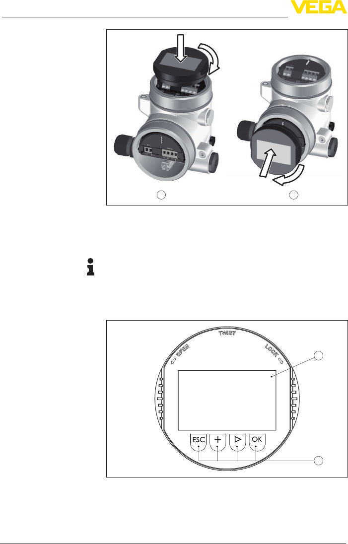
6.2 Adjustment system
1
2
Fig. 43: Display and adjustment elements
1 LC display
2 Adjustment keys
• [OK] key:Key functions
41
6 Set up with the display and adjustment module
VEGAPULS 69 • 4 … 20 mA/HART - two-wire
47247-EN-150615
– Move to the menu overview
– Conrmselectedmenu
– Edit parameter
– Save value
• [->] key:
– Presentation, change measured value
– Select list entry
– Select menu items in the quick setup
– Select editing position
• [+] key:
– Change value of the parameter
• [ESC] key:
– Interrupt input
– Jump to next higher menu
You adjust the instrument via the four keys of the display and adjust-
ment module. The individual menu items are shown on the LC display.
Youcanndthefunctionsoftheindividualkeysintheprevious
illustration.
By pushing the [+] and [->] keys once, the edited value or the cursor
changes by one position. By pushing the keys longer than 1 s the
change will be continuously.
By pushing the [OK] and [ESC] keys simultaneously for more than
5 s, a return to the basic menu is caused. The menu language is then
switched over to "English".
Approx. 60 minutes after the last pressing of a key, an automatic reset
tomeasuredvalueindicationistriggered.Anyvaluesnotconrmed
with [OK] will not be saved.
6.3 Measured value indication - Selection
national language
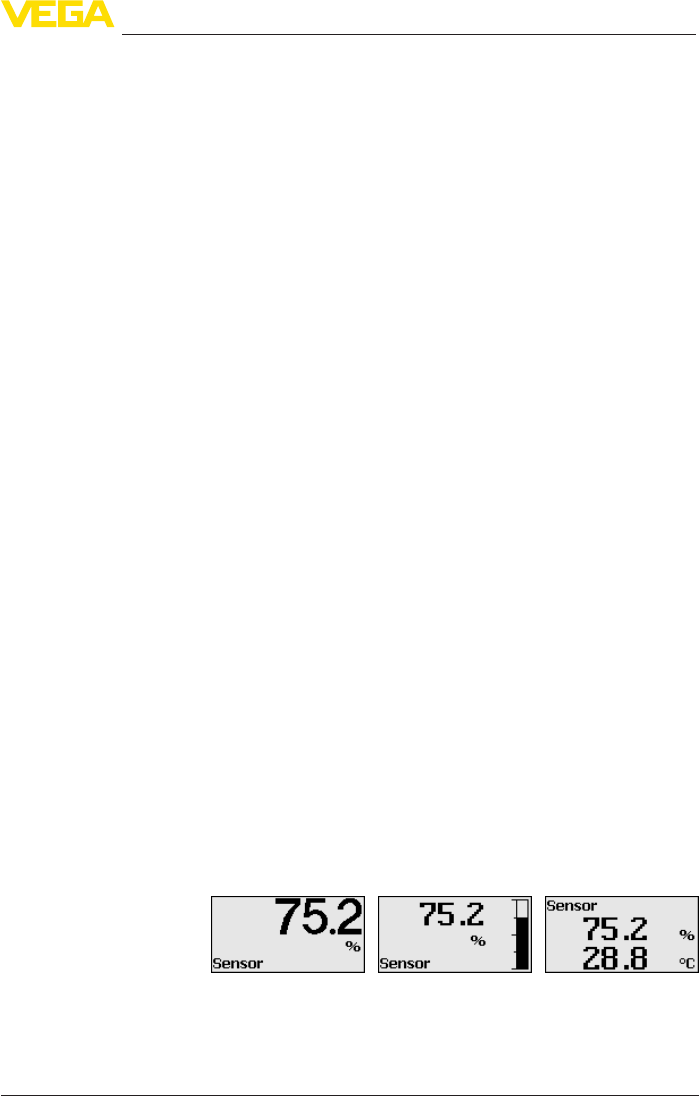
With the [->]keyyoumovebetweenthreedierentindicationmodes.
Intherstview,theselectedmeasuredvalueisdisplayedinlarge
digits.
In the second view, the selected measured value and a correspond-
ing bar graph presentation are displayed.
In the third view, the selected measured value as well as a second se-
lectable value, e.g. the temperature of the electronics, are displayed.
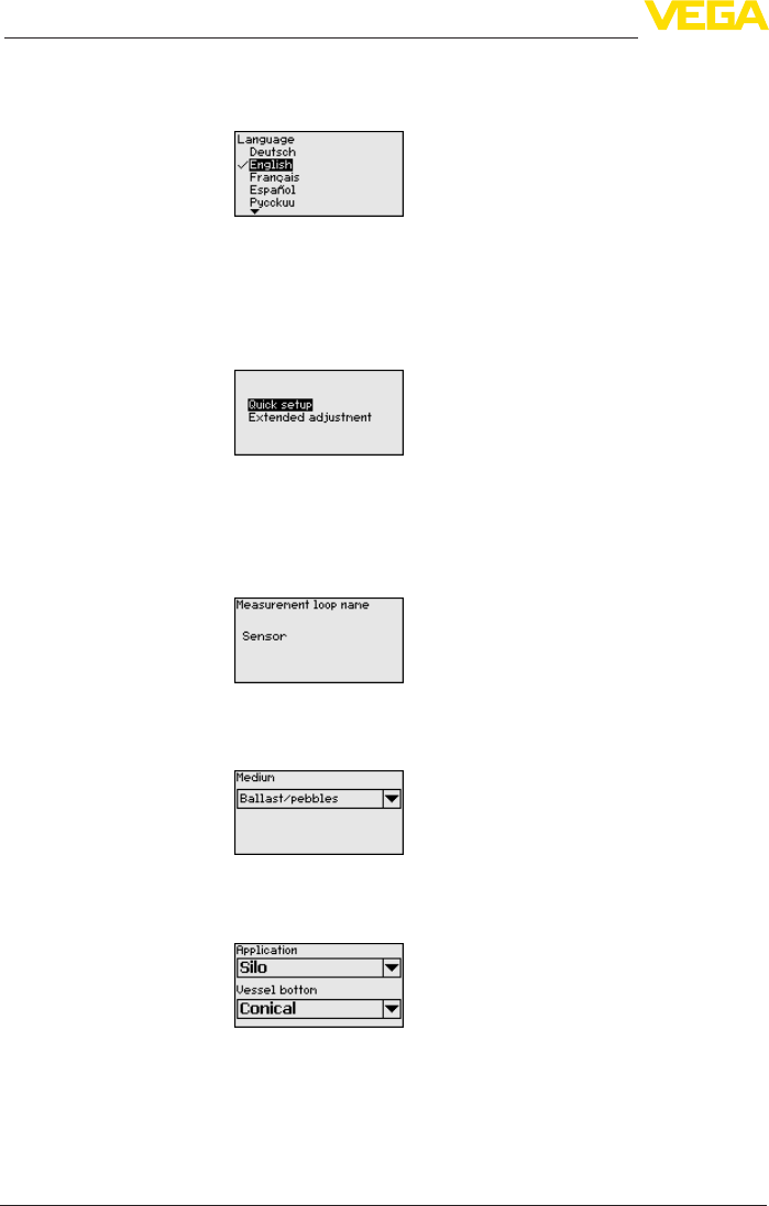
During the initial setup of an instrument shipped Ex works,use the
"OK" key to get to the menu "National language".
Adjustment system
Time functions
Measured value indica-
tion
42
6 Set up with the display and adjustment module
VEGAPULS 69 • 4 … 20 mA/HART - two-wire
47247-EN-150615
This menu item is used to select the national language for further pa-
rameter adjustment. You can change the selection via the menu item
"Setup - Display, Menu language".
With the "OK" key you move to the main menu.
6.4 Parameter adjustment - Quick setup
To quickly and easily adapt the sensor to the application, select
the menu item "Quick setup" in the start graphic on the display and
adjustment module.
Carry out the following steps with the [->] key in the below sequence.
Youcannd"Extendedadjustment" in the next sub-chapter.
1. Measurement loop name
Intherstmenuitemyouassignasuitablemeasurementloopname.
Permitted are names with max. 19 characters.
2. Medium
In this menu item you select the type of bulk solid. The selection com-
prisesdierentgranulatesizes.
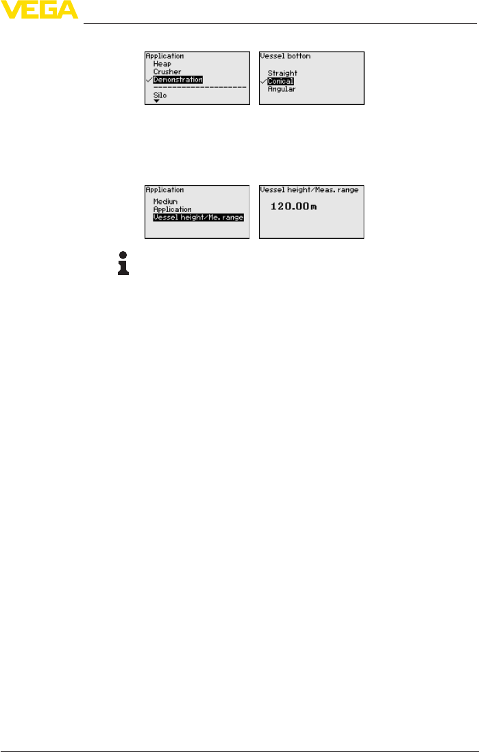
3. Application/Vessel bottom
In this menu item you specify the application and the form of the ves-
sel bottom.
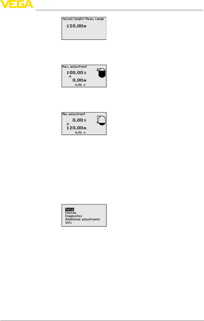
4. Vessel height/Measuring range
In this menu item you enter the height of the vessel and hence the
active measuring range.
Selection of national
language
43
6 Set up with the display and adjustment module
VEGAPULS 69 • 4 … 20 mA/HART - two-wire
47247-EN-150615
5. Max. adjustment
In this menu item you carry out the max. adjustment.
Enterthemeasuringdistancefor100%lling.
6. Min. adjustment
In this menu item you carry out the min. adjustment.
Enterthemeasuringdistancefor0%lling.
7. Termination
"Quick setup terminated successfully"isbrieydisplayed.Theecho
curve of the setup is stored automatically.
Thequicksetupisnished.
The return to the measured value indication is carried out through the
[->] or [ESC] keys or automatically after 3 s
6.5 Parameter adjustment - Extended adjustment
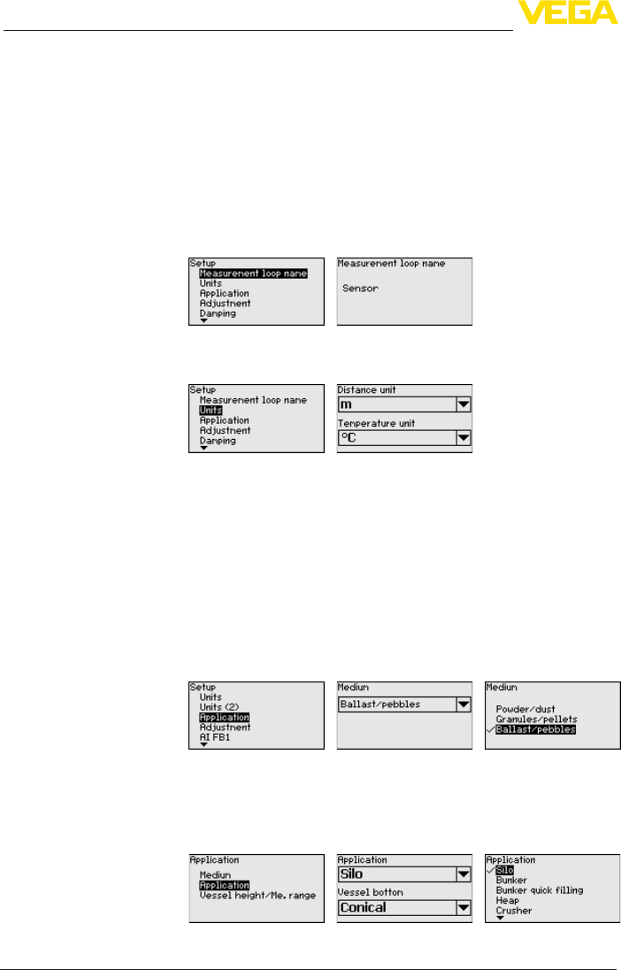
Themainmenuisdividedintovesectionswiththefollowingfunc-
tions:
Setup: Settings, e.g., for measurement loop name, units, application,
adjustment, signal output
Display: Settings, e.g., for language, measured value display, lighting
Diagnosis: Information, for example, of device status, peak value,
simulation, echo curve
Additional adjustments: Date/Time, reset, copy function, scaling,
currentoutput,falsesignalsuppression,linearization,HARTmode,
special parameters
Info: Instrument name, hardware and software version, calibration
date, instrument features
In the main menu point "Setup", the individual submenu points
should be selected one after the other and provided with the correct
Main menu
44
6 Set up with the display and adjustment module
VEGAPULS 69 • 4 … 20 mA/HART - two-wire
47247-EN-150615
parameters to ensure optimum adjustment of the measurement. The
procedure is described in the following.
Here you can assign a suitable measurement loop name. Push the
"OK" key to start the editing. With the "+" key you change the sign and
with the "->" key you jump to the next position.
You can enter names with max. 19 characters. The character set
comprises:
• Capital letters from A … Z
• Numbers from 0 … 9
• Special characters + - / _ blanks
In this menu item you select the distance unit and the temperature
unit.
For the distance units you can choose between m, in and ft and for
the temperature units °C, °F and K.
With this menu item, the sensor can be optimally adapted to the ap-
plication, the installation location or the measurement conditions. It
includes selection options for medium, application as well as vessel
height/measuring range.
Medium:
Everymediumhasadierentreectivebehaviour.Withthisselection,
the sensor can be perfectly adapted to the medium and measurement
reliability,particularlywithmediawithpoorreectiveproperties,is
considerably increased.
Application:
Depending on the type of bulk solids application, material cones and
additional echoes from the vessel wall or bottom can become further
interfering factors. Through this selection, the sensor is adapted
perfectly to the application.
Setup - Measurement
loop name
Setup - Units
Setup - Application
45
6 Set up with the display and adjustment module
VEGAPULS 69 • 4 … 20 mA/HART - two-wire
47247-EN-150615
Vessel height/Measuring range:
The VEGAPULS 69 is a radar sensor for bulk solids in high, slender
vessels. It covers a measuring range of up to 120 m. This menu item
allows a limitation of the active measuring range in which the sensor
searches for level echoes.
Information:
The min. adjustment must be carried out independently of this.
The following features form the basis of the applications:
Silo (slender and high):
• Vessel of metal: weld joints
• Process/measurement conditions:
– Filling aperture too close to the sensor
– System noise in completely empty silo increased
• Properties, sensor:
– Stable measured values through higher averaging
– False signal suppression during setup recommended, required
for automatic false signal suppression
– Automaticfalsesignalsuppressionwithpartlylledvessel1)
Bunker (large-volume):
• Vessel of concrete or metal:
– Structured vessel walls
– Installations present
• Process/measurement conditions:
– Large distance to the medium
– Large angles of repose
• Properties, sensor:
– Mean averaging
– High measured value jumps are accepted
Bunkerwithfastlling:
• Vessel of concrete or metal, also multiple chamber silo:
– Structured vessel walls
– Installations present
• Process/measurement conditions:
– Measured value jumps, e.g. through truck loading
1) Theinstrumentrecognizesifamanualfalsesignalsuppressionwascarried
out with empty vessel and high system noise. An automatic false signal sup-
pression is then carried out if a product echo was detected at the beginning
ofthellingprocess.

46
6 Set up with the display and adjustment module
VEGAPULS 69 • 4 … 20 mA/HART - two-wire
47247-EN-150615
– Large distance to the medium
– Large angles of repose
• Properties, sensor:
– Lower averaging
– Very high measured value jumps are accepted
Heap:
• Sensor mounting on movable conveyor belts
• Detectionoftheheapprole
• Heightdetectionduringlling
• Process/measurement conditions:
– Measuredvaluejumps,e.g.bytheproleoftheheaportrav-
erses
– Large angles of repose
– Measurementnearthellingstream
• Properties, sensor:
– Mean averaging
– High measured value jumps are accepted
Crusher:
• Vessel: installations, wear and protective facilities available
• Process/measurement conditions:
– Measured value jumps, e.g. through truck loading
– Fast reaction time
– Large distance to the medium
• Properties, sensor:
– Little averaging
– Max. reaction speed, very high measured value jumps are
accepted
Demonstration:
• Adjustment for all applications which are not typically level meas-
urement
– Instrument demonstration
– Object recognition/monitoring (additional settings required)
• Properties, sensor:
– Sensor accepts all measured value changes within the measur-
ing range immediately
– High sensitivity against interferences, because virtually no
averaging
Enter the requested parameters via the appropriate keys, save your
settings with [OK] and jump to the next menu item with the [ESC] and
the [->] key.
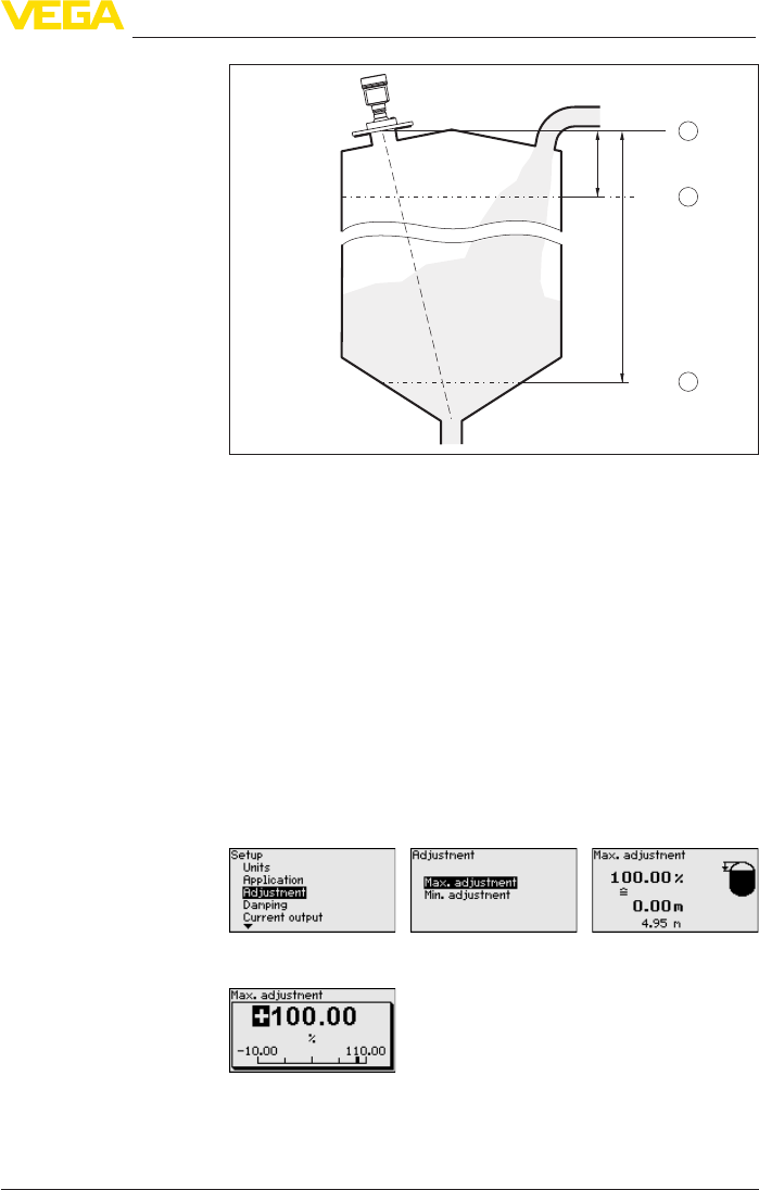
Since the radar sensor is a distance measuring instrument, the
distance from the sensor to the product surface is measured. For
indication of the real level, an allocation of the measured distance to
the percentage height must be carried out.
To perform the adjustment, enter the distance with full and empty ves-
sel, see the following example:
Setup - Adjustment
47
6 Set up with the display and adjustment module
VEGAPULS 69 • 4 … 20 mA/HART - two-wire
47247-EN-150615
2
1
3
100%
0%
1 m
(39.37
")
35 m
(1378
")
Fig.44:Parameteradjustmentexamplemin./max.adjustment
1 Min. level = max. measuring distance
2 Max. level = min. measuring distance
3 Reference plane
If these values are not known, an adjustment with the distances of for
example 10 % and 90 % is possible. Starting point for these distance
specicationsisalwaysthesealsurfaceofthethreadorange.You
canndspecicationsofthereferenceplaneinchapter"Technical
data". By means of these settings, the real level will be calculated.
The real product level during this adjustment is not important, be-
cause the min./max. adjustment is always carried out without chang-
ing the product level. These settings can be made ahead of time
without the instrument having to be installed.
Proceed as follows:
1. Select with [->]themenuitemMax.adjustmentandconrmwith
[OK].
2. Prepare the percentage value for editing with [OK] and set the
cursor to the requested position with [->].
3. Set the requested percentage value with [+] and save with [OK].
The cursor jumps now to the distance value.
Setup - Max. adjustment
48
6 Set up with the display and adjustment module
VEGAPULS 69 • 4 … 20 mA/HART - two-wire
47247-EN-150615
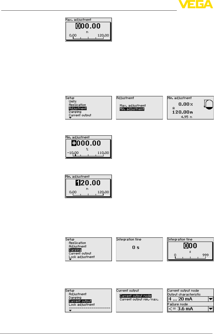
4. For the full vessel, enter the distance value in m matching the
percentage value.
5. Save settings with [OK] and move with [ESC] and [->] to Min.
adjustment.
Proceed as follows:
1. Select with [->] the menu item "Min. adjustment"andconrmwith
[OK].
2. Edit the percentage value with [OK] and set the cursor to the
requested position with [->].
3. Set the requested percentage value with [+] and save with [OK].
The cursor jumps now to the distance value.
4. Enter the suitable distance value in m for the empty vessel (e.g.
distance from the sensor to the vessel bottom) corresponding to
the percentage value.
Todampprocess-dependentmeasuredvalueuctuations,setan
integration time of 0 … 999 s in this menu item.
The default setting is a damping of 0 s.
In the menu item "Current output mode" you determine the output
characteristics and reaction of the current output in case of failure.
The default setting is output characteristics 4 … 20 mA, failure mode
< 3.6 mA.
Setup - Min. adjustment
Setup - Damping
Setup - Current output
mode
49
6 Set up with the display and adjustment module
VEGAPULS 69 • 4 … 20 mA/HART - two-wire
47247-EN-150615
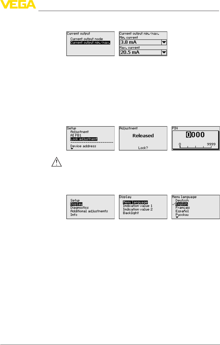
In the menu item "CurrentoutputMin./Max.", you determine the reac-
tion of the current output during operation.
The default setting is min. current 3.8 mA and max. current 20.5 mA.
In the menu item "Lock/unlockadjustment", you can protect the sen-
sorparametersagainstunauthorizedorinadvertentmodication.The
PIN is activated/deactivated permanently.
With active PIN, only the following adjustment functions are possible
without entering a PIN:
• Select menu items and show data
• Read data from the sensor into the display and adjustment mod-
ule.
Caution:
With active PIN, adjustment via PACTware/DTM as well as other
systems is also blocked.
This menu item enables the setting of the requested national lan-
guage.
The following languages are available:
• German
• English
• French
• Spanish
• Russian
• Italian
• Dutch
• Portuguese
• Japanese
• Chinese
• Polish
• Czech
• Turkish
In the delivery status, the VEGAPULS 69 is set to the ordered national
language.
Setup - Current output
Min./Max.
Lock/unlock setup - Ad-
justment
Display - Menu language
50
6 Set up with the display and adjustment module
VEGAPULS 69 • 4 … 20 mA/HART - two-wire
47247-EN-150615
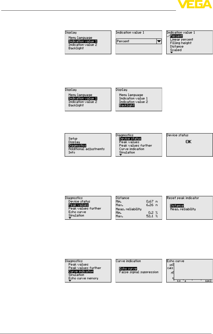
Inthismenuitemyoucandenethewaymeasuredvaluesareindi-
cated on the display.
The default setting for the display value is "Percent".
The display and adjustment module has a backlight for the display. In
thismenuitemyoucanswitchthelightingonoro.Youcanndthe
required operating voltage in chapter "Technicaldata".
In delivery status, the lighting is switched on.
In this menu item, the device status is displayed.
The min. and max. measured value, the measurement reliability as
well as the min. and max. electronics temperature are stored in the
sensor. The values are displayed in the menu item "Peak value".
A reset menu is opened with the [OK] key in the respective peak
value window:
With the [OK] key in the reset menu, the peak values are reset to the
actual measured value.
The "Echocurve" shows the signal strength of the echoes over the
measuring range in dB. The signal strength enables an evaluation of
the quality of the measurement.
Theselectedcurveiscontinuouslyupdated.Asubmenuwithzoom
functions is opened with the [OK] key:
• "X-Zoom":Zoomfunctionforthemeas.distance
• "Y-Zoom":1,2,5and10xsignalmagnicationin"dB"
• "Unzoom":Resetthepresentationtothenominalmeasuringrange
withoutmagnication
Display - Displayed value
1 and 2
Display - Backlight
Diagnostics - Device
status
Diagnosis - Peak value
Diagnoses - Curve indica-
tion
51
6 Set up with the display and adjustment module
VEGAPULS 69 • 4 … 20 mA/HART - two-wire
47247-EN-150615
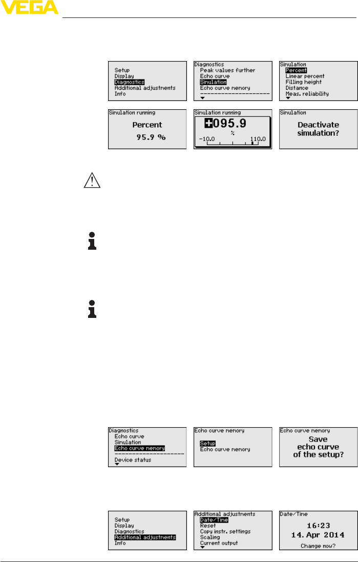
In this menu item you can simulate measured values via the current
output. This allows the signal path to be tested, e.g. through down-
stream indicating instruments or the input card of the control system.
Select the requested simulation variable and set the requested value.
Caution:
During simulation, the simulated value is outputted as 4 … 20 mA cur-
rent value and as digital HART signal. The status message within the
context of the asset management function is "Maintenance".
Push the [ESC] key to deactivate the simulation.
Information:
The simulation is terminated automatically 60 minutes after the last
key has been pressed.
The function "Setup" allows the echo curve to be saved at the time of
setup.
Information:
This is generally recommended, however, for use of the Asset
Management functions it is absolutely necessary. Saving should be
carried out with a very low level.
The function "Echocurvememory" allows up to ten individual echo
curves to be stored, for example to detect the measurement behav-
iourofthesensorindierentoperatingconditions.
With the adjustment software PACTware and the PC, the stored echo
curvescanbedisplayedwithhighresolutionandusedtorecognize
signal changes over time. In addition, the echo curve saved during
setup can also be displayed in the echo curve window and compared
with the actual echo curve.
In this menu item, the internal clock of the sensor is set to the request-
ed time and time format. At the time of shipment from factory, the
instrument is set to CET (Central European Time).
Diagnosis - Simulation
Diagnostics - Echo curve
memory
Additional adjustments -
Date Time
52
6 Set up with the display and adjustment module
VEGAPULS 69 • 4 … 20 mA/HART - two-wire
47247-EN-150615
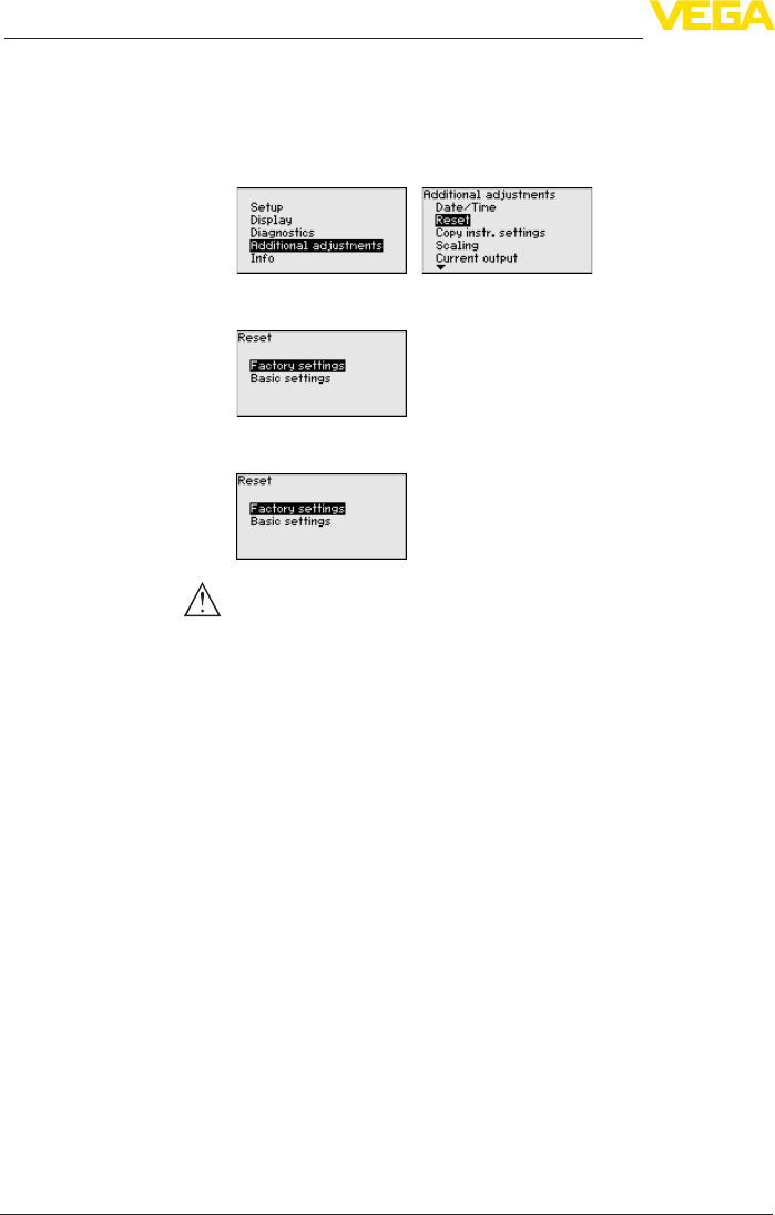
During a reset, the parameter settings carried out by the user are
reset to the default values (see below table).
Proceed as follows:
1. Select with [->] under "Additional adjustments" the menu item
"Reset"andconrmwith[OK].
2. Conrmwith[OK] and select the requested reset function with
[->]
3. Conrmwith[OK], for approx. 5 s the message "Resetting" is
displayed, then the selection window appears.
Caution:
For the duration of the reset, the set trouble signal is outputted via the
current output. Within the context of the asset management function,
the message "Maintenance" is outputted.
The following reset functions are available:
Delivery status: Restores the parameter settings at the time of ship-
mentfromthefactory,incl.theorder-specicsettings.Anycreated
falsesignalsuppression,user-programmablelinearizationcurveas
well as measured value and echo curve memory is deleted. The event
andparametermodicationmemoriesremainunaected.
Basic settings: Resets the parameter settings, incl. special param-
eters, to the default values of the respective instrument. Any stored
false signal suppression or user programmable linearisation curve, as
well as the measured value memory, is deleted. Order-related settings
are not taken over into the current parameters after this reset.
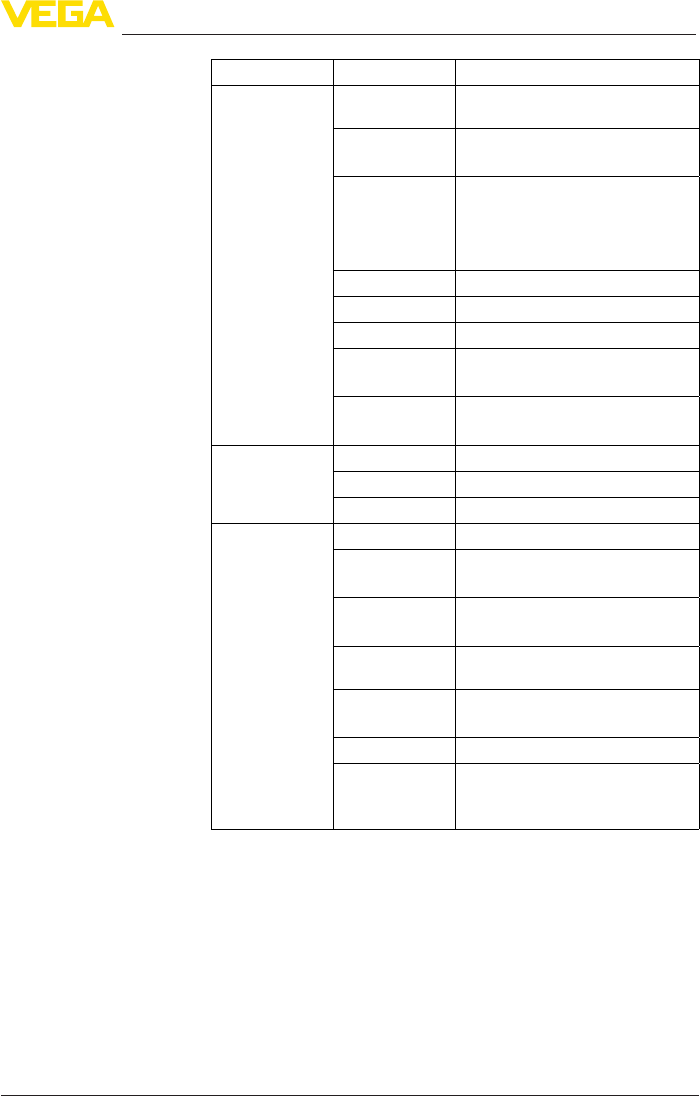
The following table shows the scope of the reset function and the
default values of the instrument:
Additional adjustments
- Reset
53
6 Set up with the display and adjustment module
VEGAPULS 69 • 4 … 20 mA/HART - two-wire
47247-EN-150615
Menu Menu item Default value
Setup Measurement
loop name
Sensor
Units Distance in m
Temperature in °C
Application Medium: Crushed stones/gravel
Application: Silo
Vessel bottom: Flat
Vessel height/Measuring range: 120 m
Min. adjustment 120 m
Max. adjustment 0,000 m(d)
Damping 0.0 s
Current output
mode
Output characteristics: 4 … 20 mA
Failure mode: < 3.6 mA ▼
Current output
Min./Max.
Min. current: 3.8 mA
Max. current: 20.5 mA
Display Displayed value 1 Filling height
Displayed value 2 Temperature
Backlight Switchedo
Additional adjust-
ments
Date/Time Time format: 24 h
Scalingsize Volume
l
Scaling format 100.00 lin %, 100 l
0.00 lin %, 0 l
Current output 1
and2size
Lin %
Current output 1
and 2 adjustment
100.00 %, 100 l
0.00 %, 0 l
Linearization Linear
HART mode HART address: 0
Loop current mode: Analogue cur-
rent output
The instrument settings are copied with this function. The following
functions are available:
Read from sensor: Read data from sensor and store into the display
and adjustment module
Write into sensor: Store data from the display and adjustment mod-
ule back into the sensor
The following data or settings for adjustment of the display and ad-
justment module are saved:
• All data of the menu "Setup" and "Display"
Additional adjustments -
Copy instrument settings
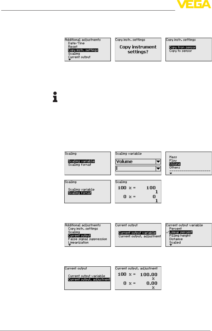
54
6 Set up with the display and adjustment module
VEGAPULS 69 • 4 … 20 mA/HART - two-wire
47247-EN-150615
• The menu items "Reset,Date/Time" in the menu "Additional set-
tings"
• Theuser-programmablelinearizationcurve
The copied data are permanently saved in an EEPROM memory in
the display and adjustment module and remain there even in case of
power failure. From there, they can be written into one or more sen-
sors or kept as backup for a possible electronics exchange.
Note:
Before the data are saved in the sensor, a safety check is carried out
to determine if the data match the sensor. In the process the sensor
type of the source data as well as the target sensor are displayed. If
the data do not match, a fault message is outputted or the function is
blocked. The data are saved only after release.
In the menu item "Scaling"youdenethescalingvariableandthe
scaling format for the indication of the level measured value for 0 %
and 100 % on the display, for example as volume in l.
In menu item "Current output, variable" you specify which measured
variable the current output refers to.
In menu item "Current output, adjustment" you can assign a respec-
tive measured value to the current output.
Thefollowingcircumstancescauseinterferingreectionsandcan
inuencethemeasurement:
• High sockets
• Vessel installations such as struts
Additional settings - Scal-
ing
Additional settings - Cur-
rent output 1 and 2 (size)
Additional settings -
Current output 1 and 2
(adjustment)
Additional adjustments -
False signal suppression
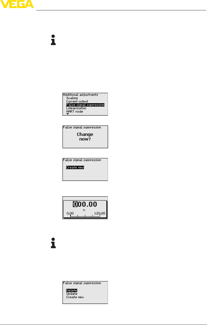
55
6 Set up with the display and adjustment module
VEGAPULS 69 • 4 … 20 mA/HART - two-wire
47247-EN-150615
• Agitators
• Buildup or welded joints on vessel walls
Note:
A false signal suppression detects, marks and saves these false
signals so that they are no longer taken into account in the level
measurement.
This should be done with a low level so that all potential interfering
reectionscanbedetected.
Proceed as follows:
1. Select with [->] the menu item "False signal suppression" and
conrmwith[OK].
2. Conrmagainwith[OK].
3. Conrmagainwith[OK].
4. Conrmagainwith[OK] and enter the actual distance from the
sensor to the product surface.
5. All interfering signals in this section are detected by the sensor
andstoredafterconrmingwith[OK].
Note:
Check the distance to the product surface, because if an incorrect
(too large) value is entered, the existing level will be saved as a false
signal. The level would then no longer be detectable in this area.
If a false signal suppression has already been saved in the sensor,
the following menu window appears when selecting "False signal
suppression":
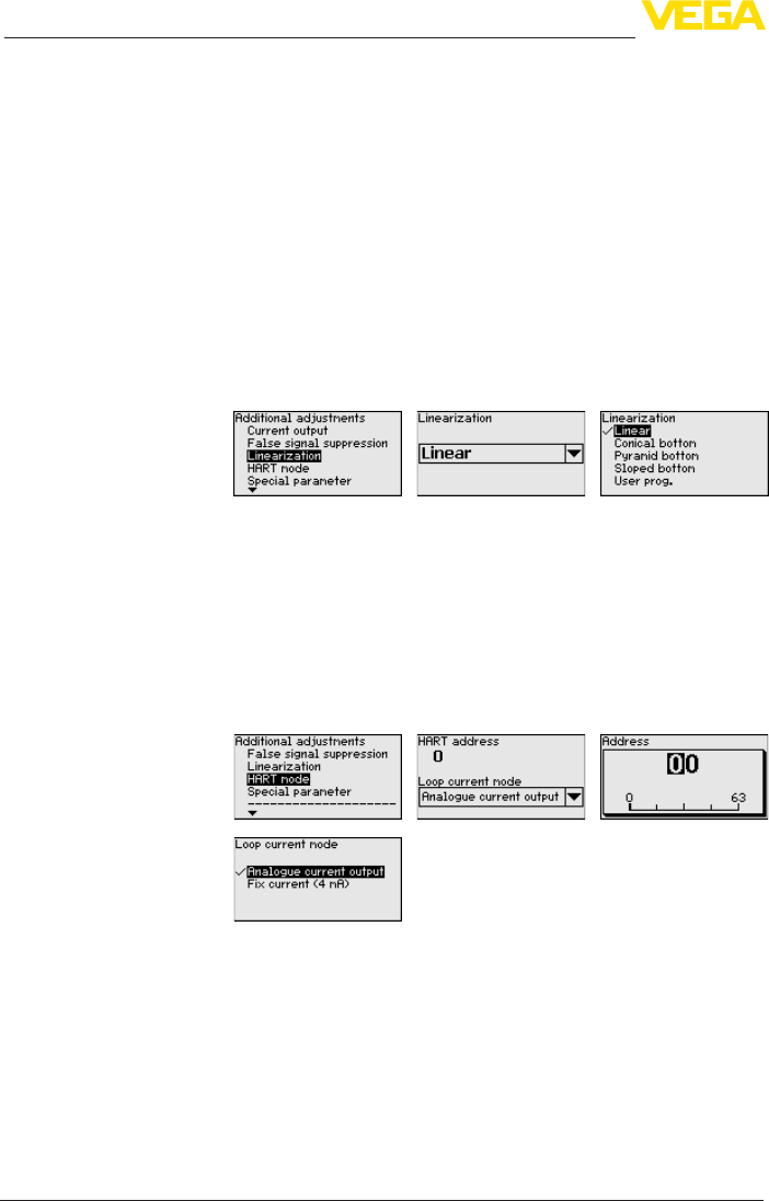
56
6 Set up with the display and adjustment module
VEGAPULS 69 • 4 … 20 mA/HART - two-wire
47247-EN-150615
Delete: An already created false signal suppression will be com-
pletely deleted. This is useful if the saved false signal suppression no
longer matches the metrological conditions in the vessel.
Extend: is used to extend an already created false signal suppres-
sion. This is useful if a false signal suppression was carried out with
a too high level and not all false signals could be detected. When
selecting "Extend", the distance to the product surface of the created
false signal suppression is displayed. This value can now be changed
and the false signal suppression can be extended to this range.
Alinearizationisnecessaryforallvesselsinwhichthevesselvolume
doesnotincreaselinearlywiththelevel.Correspondinglinearization
curves are preprogrammed for these vessels. They represent the
correlation between the level percentage and vessel volume. The
linearizationappliestothemeasuredvalueindicationandthecurrent
output.
In this menu item you determine the HART mode and enter the ad-
dress for multidrop mode.
In the mode "Fixed current output" up to 63 sensors can be operated
on one two-wire cable (Multidrop operation). An address between 0
and 63 must be assigned to each sensor.
When chosing the function "Analogue current output", then a
4 … 20 mA signal is outputted in multidrop mode.
With the mode "Fixed current (4 mA)"axed4mAsignalisoutputted
independently of the actual level.
The default setting is "Analogue current output" and the address "00".
In this menu item you gain access to the protected area where
you can enter special parameters. In exceptional cases, individual
parameterscanbemodiedinordertoadaptthesensortospecial
requirements.
Change the settings of the special parameters only after having con-
tactedourservicesta.
Additional adjustments -
Linearization
Additional adjustments -
HART mode
Additional adjustments -
Special parameters
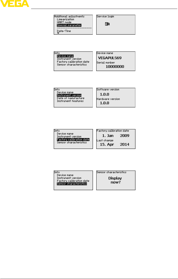
57
6 Set up with the display and adjustment module
VEGAPULS 69 • 4 … 20 mA/HART - two-wire
47247-EN-150615
In this menu item, you can read out the instrument name and the
instrument serial number:
In this menu item, the hardware and software version of the sensor is
displayed.
In this menu item, the date of factory calibration of the sensor as well
as the date of the last change of sensor parameters are displayed via
the display and adjustment module or via the PC.
In this menu item, the features of the sensor such as approval, pro-
cesstting,seal,measuringrange,electronics,housingandothers
are displayed.
6.6 Saving the parameter adjustment data
We recommended noting the adjusted data, e.g. in this operating
instructions manual, and archiving them afterwards. They are thus
available for multiple use or service purposes.
If the instrument is equipped with a display and adjustment module,
the data in the sensor can be saved in the display and adjustment
module. The procedure is described in the operating instructions
manual "Display and adjustment module" in the menu item "Copy
sensor data". The data remain there permanently even if the sensor
power supply fails.
The following data or settings for adjustment of the display and ad-
justment module are saved:
• All data of the menu "Setup" and "Display"
Info - Instrument name
Info - Instrument version
Info - Factory calibration
date
Info - Sensor character-
istics

58
6 Set up with the display and adjustment module
VEGAPULS 69 • 4 … 20 mA/HART - two-wire
47247-EN-150615
• In the menu "Additional settings" the items "Sensor-specicunits,
temperature unit and linearization"
• Thevaluesoftheuserprogrammablelinearizationcurve
The function can also be used to transfer settings from one instru-
ment to another instrument of the same type. If it is necessary to
exchange a sensor, the display and adjustment module is inserted
into the replacement instrument and the data are likewise written into
the sensor via the menu item "Copy sensor data".
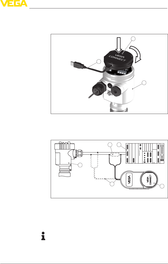
59
7 Setup with PACTware
VEGAPULS 69 • 4 … 20 mA/HART - two-wire
47247-EN-150615
7 Setup with PACTware
7.1 Connect the PC
3
1
2
Fig. 45: Connection of the PC directly to the sensor via the interface adapter
1 USBcabletothePC
2 InterfaceadapterVEGACONNECT
3 Sensor
1
5
2 4
3
OPEN
TWIST
USB
LOCK
Fig.46:ConnectingthePCviaHARTtothesignalcable
1 Sensor
2 HARTresistance250Ω(optionaldependingonprocessing)
3 Connection cable with 2 mm pins and terminals
4 Processingsystem/PLC/Voltagesupply
5 Interfaceadapter,forexampleVEGACONNECT4
Note:
With power supply units with integrated HART resistance (internal
resistanceapprox.250Ω),anadditionalexternalresistanceisnot
necessary. This applies, e.g. to the VEGA instruments VEGATRENN
149A, VEGAMET 381, VEGAMET 391. Common Ex separators are
alsousuallyequippedwithasucientcurrentlimitationresistance.In
Via the interface adapter
directly on the sensor
Via the interface adapter
and HART
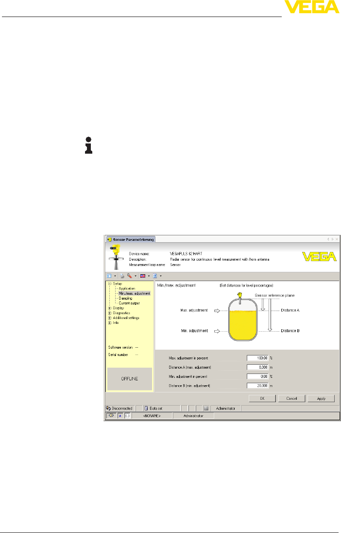
60
7 Setup with PACTware
VEGAPULS 69 • 4 … 20 mA/HART - two-wire
47247-EN-150615
such cases, the interface converter can be connected parallel to the
4 … 20 mA cable (dashed line in the previous illustration).
7.2 Parameter adjustment
For parameter adjustment of the instrument via a Windows PC, the
congurationsoftwarePACTwareandasuitableinstrumentdriver
(DTM) according to FDT standard are required. The latest PACTware
version as well as all available DTMs are compiled in a DTM Collec-
tion. The DTMs can also be integrated into other frame applications
according to FDT standard.
Note:
To ensure that all instrument functions are supported, you should
always use the latest DTM Collection. Furthermore, not all described
functionsareincludedinolderrmwareversions.Youcandownload
the latest instrument software from our homepage. A description of
the update procedure is also available in the Internet.
Further setup steps are described in the operating instructions manu-
al "DTMCollection/PACTware" attached to each DTM Collection and
which can also be downloaded from the Internet. Detailed descrip-
tions are available in the online help of PACTware and the DTMs.
Fig.47:ExampleofaDTMview
All device DTMs are available as a free-of-charge standard version
and as a full version that must be purchased. In the standard version,
all functions for complete setup are already included. An assistant for
simpleprojectcongurationsimpliestheadjustmentconsiderably.
Saving/printing the project as well as import/export functions are also
part of the standard version.
In the full version there is also an extended print function for complete
project documentation as well as a save function for measured value
Prerequisites
Standard/Full version

61
7 Setup with PACTware
VEGAPULS 69 • 4 … 20 mA/HART - two-wire
47247-EN-150615
and echo curves. In addition, there is a tank calculation program as
well as a multiviewer for display and analysis of the saved measured
value and echo curves.
The standard version is available as a download under
www.vega.com/downloads and "Software". The full version is avail-
able on CD from the agency serving you.
7.3 Saving the parameter adjustment data
We recommend documenting or saving the parameter adjustment
data via PACTware. That way the data are available for multiple use or
service purposes.

62
8 Set up with other systems
VEGAPULS 69 • 4 … 20 mA/HART - two-wire
47247-EN-150615
8 Set up with other systems
8.1 DD adjustment programs
Device descriptions as Enhanced Device Description (EDD) are
available for DD adjustment programs such as, for example, AMS™
and PDM.
Thelescanbedownloadedatwww.vega.com/downloads under
"Software".
8.2 Field Communicator 375, 475
Device descriptions for the instrument are available as EDD for pa-
rameter adjustment with the Field Communicator 375 or 475.
For the integration of the EDD in the Field Communicator 375 or 475,
the software "Easy Upgrade Utility" is required which is available from
the manufacturer. This software is updated via the Internet and new
EDDs are automatically taken over into the device catalogue of this
software after they are released by the manufacturer. They can then
be transferred to a Field Communicator.

63
9 Diagnosis, asset management and service
VEGAPULS 69 • 4 … 20 mA/HART - two-wire
47247-EN-150615
9 Diagnosis, asset management and service
9.1 Maintenance
If the device is used correctly, no maintenance is required in normal
operation.
Insomeapplications,buildupontheantennasystemcaninuence
the measuring result. Depending on the sensor and application, make
arrangements to avoid strong pollution of the antenna system. If nec-
essary, clean the antenna system in certain intervals.
9.2 Measured value and event memory
The instrument has several memories which are available for diagno-
sis purposes. The data remain even with voltage interruption.
Up to 100,000 measured values can be stored in the sensor in a ring
memory. Each entry contains date/time as well as the respective
measured value. Storable values are for example:
• Distance
• Filling height
• Percentage value
• Lin. percent
• Scaled
• Current value
• Meas. reliability
• Electronics temperature
When the instrument is shipped, the measured value memory is
active and stores distance, measurement certainty and electronics
temperature every 3 minutes.
The requested values and recording conditions are set via a PC with
PACTware/DTM or the control system with EDD. Data are thus read
out and also reset.
Up to 500 events are automatically stored with a time stamp in the
sensor (non-deletable). Each entry contains date/time, event type,
event description and value. Event types are for example:
• Modicationofaparameter
• Switch-onandswitch-otimes
• Status messages (according to NE 107)
• Error messages (according to NE 107)
The data are read out via a PC with PACTware/DTM or the control
system with EDD.
The echo curves are stored with date and time and the corresponding
echo data. The memory is divided into two sections:
Echo curve of the setup: This is used as reference echo curve for
the measurement conditions during setup. Changes in the measure-
ment conditions during operation or buildup on the sensor can thus
berecognized.Theechocurveofthesetupisstoredvia:
Measured value memory
Event memory
Echo curve memory
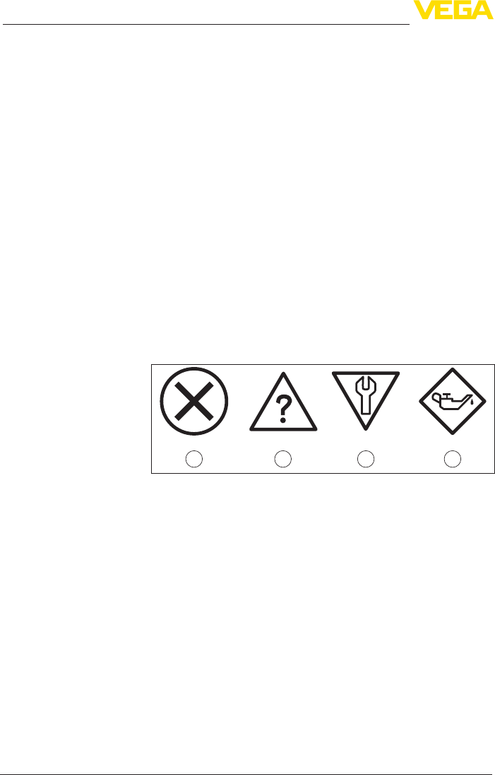
64
9 Diagnosis, asset management and service
VEGAPULS 69 • 4 … 20 mA/HART - two-wire
47247-EN-150615
• PC with PACTware/DTM
• Control system with EDD
• Display and adjustment module
Further echo curves: Up to 10 echo curves can be stored in a ring
buerinthismemorysection.Furtherechocurvesarestoredvia:
• PC with PACTware/DTM
• Control system with EDD
9.3 Asset Management function
The instrument features self-monitoring and diagnostics according to
NE 107 and VDI/VDE 2650. In addition to the status messages in the
following tables, detailed error messages are available under menu
item "Diagnostics" via the display and adjustment module, PACTware/
DTM and EDD.
The status messages are divided into the following categories:
• Failure
• Function check
• Outofspecication
• Maintenance requirement
and explained by pictographs:
41 2 3
Fig. 48: Pictographs of the status messages
1 Failure - red
2 Outofspecication-yellow
3 Function check - orange
4 Maintenance - blue
Failure: Due to a malfunction in the instrument, a failure message is
outputted.
This status message is always active. It cannot be deactivated by the
user.
Function check: The instrument is in operation, the measured value
is temporarily invalid (for example during simulation).
This status message is inactive by default. It can be activated by the
user via PACTware/DTM or EDD.
Outofspecication: The measured value is unstable because the
instrumentspecicationisexceeded(e.g.electronicstemperature).
This status message is inactive by default. It can be activated by the
user via PACTware/DTM or EDD.
Status messages
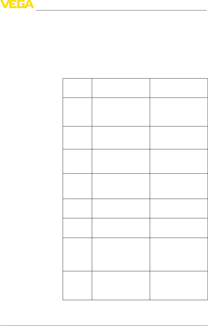
65
9 Diagnosis, asset management and service
VEGAPULS 69 • 4 … 20 mA/HART - two-wire
47247-EN-150615
Maintenance:Duetoexternalinuences,theinstrumentfunction
islimited.Themeasurementisaected,butthemeasuredvalueis
still valid. Plan in maintenance for the instrument because a failure is
expected in the near future (e.g. due to buildup).
This status message is inactive by default. It can be activated by the
user via PACTware/DTM or EDD.
The following table shows the error codes in the status message
"Failure"andgivesinformationonthereasonandrectication.Keep
in mind that some information is only valid with four-wire instruments.
Code
Text mes-
sage
Cause Rectication
F013
no measured
value avail-
able
– Sensor does not detect an
echo during operation
– Antenna system dirty or
defective
– Check or correct installation
and/or parameter adjust-
ment
– Clean or exchange process
component or antenna
F017
Adjustment
span too small
– Adjustment not within
specication
– Change adjustment accord-
ing to the limit values (dif-
ference between min. and
max.≥10mm)
F025
Error in the
linearization
table
– Index markers are not con-
tinuously rising, for example
illogical value pairs
– Checklinearizationtable
– Delete table/Create new
F036
No operable
software
– Failed or interrupted soft-
ware update
– Repeat software update
– Check electronics version
– Exchanging the electronics
– Send instrument for repair
F040
Error in the
electronics
– Hardware defect – Exchanging the electronics
– Send instrument for repair
F080
General soft-
ware error
– General software error – Disconnect operating volt-
agebriey
F105
Determine
measured
value
– The instrument is still in the
start phase, the measured
value could not yet be
determined
– Wait for the end of the
switch-on phase
– Duration depending on
the version and parameter
adjustment up to approxi-
mately 3 min.
F113
Communica-
tion error
– EMC interference
– Transmission error with the
external communication
with 4-wire power supply
unit
– RemoveEMCinuences
– Exchange 4-wire power
supply unit or electronics
Failure
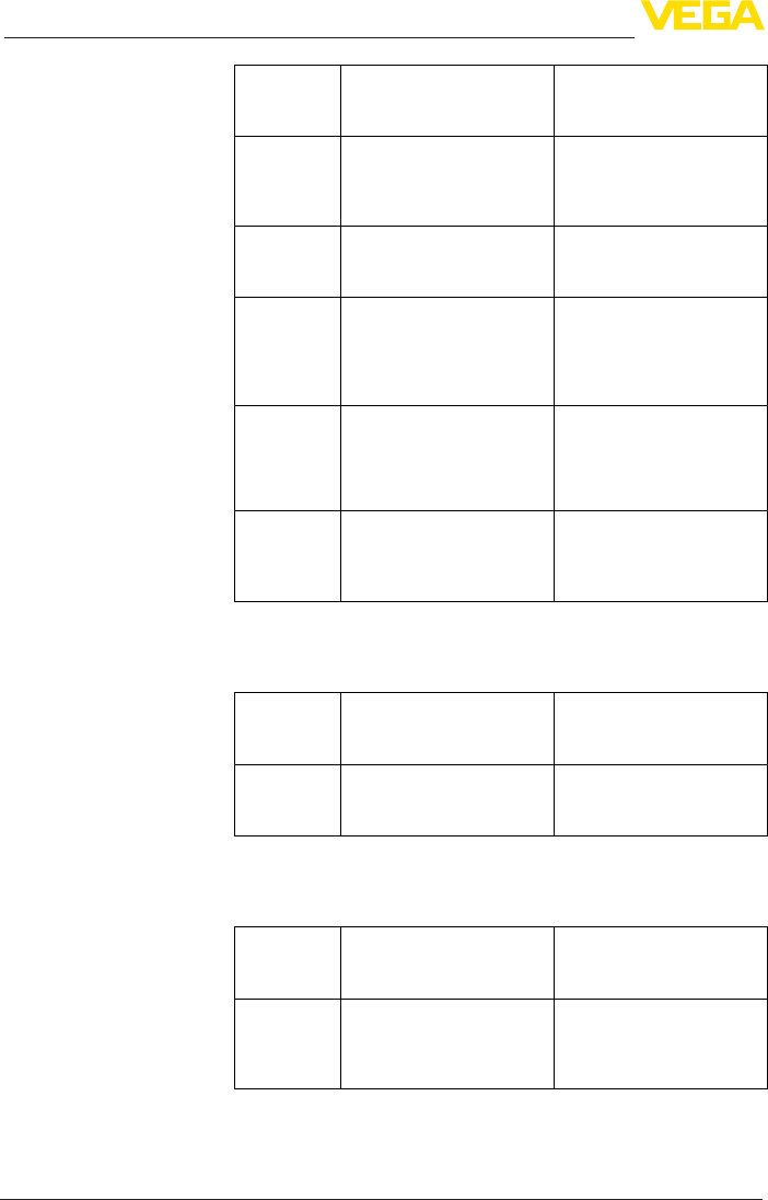
66
9 Diagnosis, asset management and service
VEGAPULS 69 • 4 … 20 mA/HART - two-wire
47247-EN-150615
Code
Text mes-
sage
Cause Rectication
F125
Impermissi-
ble electronics
temperature
– Temperature of the elec-
tronicsinthenon-specied
range
– Check ambient temperature
– Isolate electronics
– Use instrument with higher
temperature range
F260
Error in the
calibration
– Error in the calibration car-
ried out in the factory
– Error in the EEPROM
– Exchanging the electronics
– Send instrument for repair
F261
Error in the
instrument
settings
– Error during setup
– False signal suppression
faulty
– Error when carrying out a
reset
– Repeat setup
– Carry out a reset
F264
Installation/
Setup error
– Adjustment not within the
vessel height/measuring
range
– Max. measuring range of
theinstrumentnotsucient
– Check or correct installation
and/or parameter adjust-
ment
– Use an instrument with big-
ger measuring range
F265
Measurement
function dis-
turbed
– Sensor no longer carries
out a measurement
– Operating voltage too low
– Check operating voltage
– Carry out a reset
– Disconnect operating volt-
agebriey
The following table shows the error codes and text messages in the
status message "Function check" and provides information on causes
as well as corrective measures.
Code
Text mes-
sage
Cause Rectication
C700
Simulation ac-
tive
– A simulation is active – Finish simulation
– Wait for the automatic end
after 60 mins.
The following table shows the error codes and text messages in the
status message "Outofspecication" and provides information on
causes as well as corrective measures.
Code
Text mes-
sage
Cause Rectication
S600
Impermissi-
ble electronics
temperature
– Temperature of the elec-
tronicsinthenon-specied
range
– Check ambient temperature
– Isolate electronics
– Use instrument with higher
temperature range
Function check
Outofspecication

67
9 Diagnosis, asset management and service
VEGAPULS 69 • 4 … 20 mA/HART - two-wire
47247-EN-150615
Code
Text mes-
sage
Cause Rectication
S603
Impermissi-
ble operating
voltage
– Operating voltage below
speciedrange
– Check electrical connection
– If necessary, increase
operating voltage
The following table shows the error codes and text messages in the
status message "Maintenance" and provides information on causes
as well as corrective measures.
Code
Text mes-
sage
Cause Rectication
M500
Error with the
reset delivery
status
– With the reset to delivery
status, the data could not
be restored
– Repeat reset
– LoadXMLlewithsensor
data into the sensor
M501
Error in the
non-active
linearization
table
– Hardware error EEPROM – Exchanging the electronics
– Send instrument for repair
M502
Error in the
event memory
– Hardware error EEPROM – Exchanging the electronics
– Send instrument for repair
M503
Meas. reliabil-
ity too low
– The echo/noise ratio is too
small for reliable measure-
ment
– Antenna dirty or defective
– Check installation and
process conditions
– Change polarisation direc-
tion
– Use instrument with higher
sensitivity
– Clean the antenna
M504
Error on an
device inter-
face
– Hardware defect – Check connections
– Exchanging the electronics
– Send instrument for repair
M505
No echo avail-
able
– Sensor does not detect an
echo during operation
– Antenna dirty or defective
– Clean the antenna
– Use a more suitable
antenna/sensor
– Remove possible false
echoes
– Optimizesensorposition
and orientation
M506
Installation/
Setup error
– Error during setup – Check or correct installation
and/or parameter adjust-
ment
Maintenance
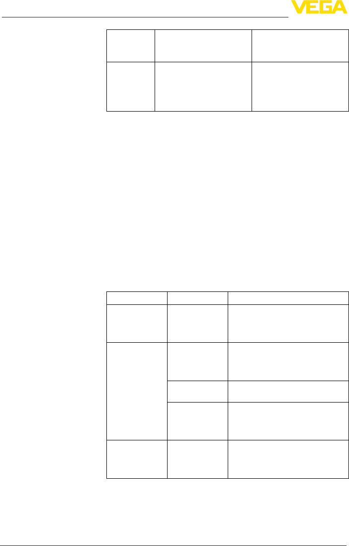
68
9 Diagnosis, asset management and service
VEGAPULS 69 • 4 … 20 mA/HART - two-wire
47247-EN-150615
Code
Text mes-
sage
Cause Rectication
M507
Error in the
instrument
settings
– Error during setup
– Error when carrying out a
reset
– False signal suppression
faulty
– Carry out reset and repeat
setup
9.4 Rectify faults
The operator of the system is responsible for taking suitable meas-
ures to rectify faults.
Therstmeasuresare:
• Evaluation of fault messages, for example via the display and
adjustment module
• Checking the output signal
• Treatment of measurement errors
Further comprehensive diagnostics options are available with a PC
with PACTware and the suitable DTM. In many cases, the reasons can
bedeterminedinthiswayandfaultsrectied.
Connect a multimeter in the suitable measuring range according to
the wiring plan. The following table describes possible errors in the
current signal and helps to eliminate them:
Error Cause Rectication
4 … 20 mA signal
not stable
– Fluctuations of
the measured
variable
– Set damping appropriate to the
instrument via the display and
adjustment module or PACTware/
DTM
4 … 20 mA signal
missing
– Electrical con-
nection faulty
– Check connection according to
chapter "Connection steps" and
if necessary, correct according to
chapter "Wiring plan"
– Voltage supply
missing
– Check cables for breaks; repair if
necessary
– Operating volt-
age too low or
load resistance
too high
– Check, adapt if necessary
Current sig-
nal greater than
22 mA or less
than 3.6 mA
– Electronics
module in the
sensor defec-
tive
– Exchange the instrument or send it
in for repair
The below tables show typical examples of application-related
measurement errors with bulk solids. A distinction is made between
measurement errors during:
• Constant level
Reaction when malfunc-
tion occurs
Procedure for fault recti-
cation
Check the 4 … 20 mA
signal
Treatment of measure-
ment errors with bulk
solids
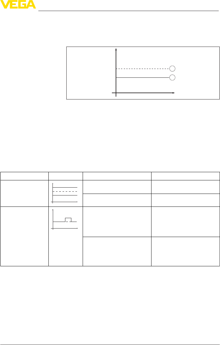
69
9 Diagnosis, asset management and service
VEGAPULS 69 • 4 … 20 mA/HART - two-wire
47247-EN-150615
• Filling
• Emptying
The images in column "Errorpattern" show the real level as a broken
line and the level displayed by the sensor as a continuous line.
1
2
Level
time
0
1 Real level
2 Level displayed by the sensor
Notes:
• Whenever the sensor displays a constant value, the reason could
also be that the fault setting of the current output is set to "Hold
value"
• If the level indication is too low, the reason could be a line resist-
ance that is too high
Measurement error with constant level
Fault description Error pattern Cause Rectication
1. Measured value
shows a too low or too
high level
Level
time
0
– Min./max. adjustment not
correct
– Adapt min./max. adjustment
– Incorrectlinearizationcurve – Adaptlinearizationcurve
2. Measured value
jumps towards 100 %
Level
time
0
– Due to the process, the
amplitude of the product echo
decreases
– A false signal suppression was
not carried out
– Carry out a false signal sup-
pression
– Amplitude or position of a false
signal has changed (e.g. con-
densation, buildup); false signal
suppression no longer matches
actual conditions
– Determine the reason for the
changed false signals, carry out
false signal suppression, e.g.
with condensation
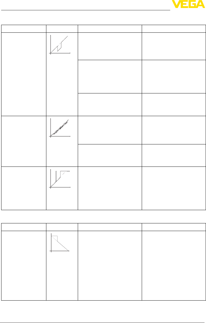
70
9 Diagnosis, asset management and service
VEGAPULS 69 • 4 … 20 mA/HART - two-wire
47247-EN-150615
Measurementerrorduringlling
Fault description Error pattern Cause Rectication
3. Measured value
jumps towards 0 %
duringlling
Level
time
0
– Amplitude of a multiple echo
(vessel top - product surface) is
larger than the level echo
– Check parameter "Application",
especially vessel top, type of
medium, dished bottom, high
dielectric constant, and adapt if
necessary
– The level echo cannot be distin-
guished from the false signal at
a false signal position (jumps to
multiple echo)
– Remove/reduce false signal:
minimizeinterferinginstalla-
tionsbychangingthepolariza-
tion direction
– Chose a more suitable installa-
tion position
– Transversereectionfroman
extraction funnel, amplitude of
thetransversereectionlarger
than the level echo
– Direct sensor to the opposite
funnel wall, avoid crossing with
thellingstream
4. Measured val-
ueuctuatesaround
10 … 20 %
Level
time
0
– Various echoes from an uneven
product surface, e.g. a material
cone
– Check parameter "Type of
medium" and adapt, if neces-
sary
– Optimizeinstallationposition
and sensor orientation
– Reectionsfromtheproduct
surface via the vessel wall
(deection)
– Select a more suitable installa-
tionposition,optimizesensor
orientation, e.g. with a swivel-
ling holder
5. Measured value
jumps sporadically to
100%duringlling
Level
time
0
– Changing condensation or con-
tamination on the antenna
– Carry out a false signal sup-
pression or increase false
signal suppression with con-
densation/contamination in the
close range by editing
– With bulk solids use radar sen-
sor with purging air connection
orexibleantennacover
Measurement error during emptying
Fault description Error pattern Cause Rectication
6. Measured value re-
mains unchanged in
the close range during
emptying
Level
time
0
– False signal larger than the
level echo
– Level echo too small
– Eliminate false signals in the
close range. Check: Antenna
must protrude out of the socket
– Remove contamination on the
antenna
– Minimizeinterferinginstal-
lations in the close range by
changingthepolarization
direction
– After eliminating the false sig-
nals, the false signal suppres-
sion must be deleted. Carry out
a new false signal suppression
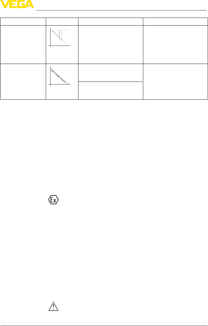
71
9 Diagnosis, asset management and service
VEGAPULS 69 • 4 … 20 mA/HART - two-wire
47247-EN-150615
Fault description Error pattern Cause Rectication
7. Measured value
jumps sporadically to-
wards 100 % during
emptying
Level
time
0
– Changing condensation or con-
tamination on the antenna
– Carry out false signal suppres-
sion or increase false signal
suppression in the close range
by editing
– With bulk solids use radar sen-
sor with purging air connection
orexibleantennacover
8. Measured val-
ueuctuatesaround
10 … 20 %
Level
time
0
– Various echoes from an uneven
product surface, e.g. an extrac-
tion funnel
– Check parameter "Type of
medium" and adapt, if neces-
sary
– Optimizeinstallationposition
and sensor orientation
– Reectionsfromtheproduct
surface via the vessel wall
(deection)
Depending on the reason for the fault and the measures taken, the
steps described in chapter "Setup" must be carried out again or must
be checked for plausibility and completeness.
Should these measures not be successful, please call in urgent cases
the VEGA service hotline under the phone no. +49 1805 858550.
The hotline is also available outside normal working hours, seven
days a week around the clock.
Sinceweoerthisserviceworldwide,thesupportisprovidedin
English. The service itself is free of charge, the only costs involved are
the normal call charges.
9.5 Exchanging the electronics module
If the electronics module is defective, it can be replaced by the user.
In Ex applications, only instruments and electronics modules with ap-
propriate Ex approval may be used.
If there is no electronics module available on site, the electronics
module can be ordered through the agency serving you. The electron-
icsmodulesareadaptedtotherespectivesensoranddierinsignal
output or voltage supply.
The new electronics module must be loaded with the default settings
of the sensor. These are the options:
• In the factory
• Or on site by the user
In both cases, the serial number of the sensor is needed. The serial
numbers are stated on the type label of the instrument, on the inside
of the housing as well as on the delivery note.
Whenloadingonsite,rstofalltheorderdatamustbedownloaded
from the Internet (see operating instructions manual "Electronics
module").
Caution:
Alluser-specicsettingsmustbeenteredagain.Hence,youhaveto
carry out a new setup after the electronics exchange.
Reaction after fault recti-
cation
24 hour service hotline

72
9 Diagnosis, asset management and service
VEGAPULS 69 • 4 … 20 mA/HART - two-wire
47247-EN-150615
If you have stored the data of the parameter adjustment during the
rstsetupofthesensor,youcantransferthesetothereplacement
electronics module. A new setup is no more necessary.
9.6 Software update
The following components are required to update the instrument
software:
• Instrument
• Voltage supply
• Interface adapter VEGACONNECT
• PC with PACTware
• Currentinstrumentsoftwareasle
Youcanndthecurrentinstrumentsoftwareaswellasdetailed
information on the procedure under "www.vega.com/downloads" and
"Software".
Caution:
Instruments with approvals can be bound to certain software versions.
Thereforemakesurethattheapprovalisstilleectiveafterasoftware
update is carried out.
Youcannddetailedinformationatwww.vega.com/downloads and
"Approvals".
9.7 How to proceed if a repair is necessary
Youcanndarepairformaswellasdetailedinformationonhowto
proceed at www.vega.com/downloads and "Formsandcerticates".
By doing this you help us carry out the repair quickly and without hav-
ing to call back for needed information.
If a repair is necessary, please proceed as follows:
• Printandlloutoneformperinstrument
• Clean the instrument and pack it damage-proof
• Attach the completed form and, if need be, also a safety data
sheet outside on the packaging
• Please contact the agency serving you to get the address for
thereturnshipment.Youcanndtheagencyonourhomepage
www.vega.com.

73
10 Dismount
VEGAPULS 69 • 4 … 20 mA/HART - two-wire
47247-EN-150615
10 Dismount
10.1 Dismounting steps
Warning:
Before dismounting, be aware of dangerous process conditions such
as e.g. pressure in the vessel or pipeline, high temperatures, cor-
rosive or toxic products etc.
Take note of chapters "Mounting" and "Connecting to power supply"
and carry out the listed steps in reverse order.
10.2 Disposal
The instrument consists of materials which can be recycled by spe-
cialised recycling companies. We use recyclable materials and have
designed the parts to be easily separable.
Correctdisposalavoidsnegativeeectsonhumansandtheenviron-
ment and ensures recycling of useful raw materials.
Materials: see chapter "Technicaldata"
If you have no way to dispose of the old instrument properly, please
contact us concerning return and disposal.
WEEE directive 2002/96/EG
This instrument is not subject to the WEEE directive 2002/96/EG and
the respective national laws. Pass the instrument directly on to a spe-
cialised recycling company and do not use the municipal collecting
points. These may be used only for privately used products according
to the WEEE directive.

74
11 Supplement
VEGAPULS 69 • 4 … 20 mA/HART - two-wire
47247-EN-150615
11 Supplement
11.1 Technical data
General data
316L corresponds to 1.4404 or 1.4435
Materials, wetted parts
Ʋ Processtting 316L, Alloy C22 (2.4602), Alloy 400 (2.4360)
ƲProcess seal On site
ƲAntenna PP, PEEK
Ʋseal, antenna system FKM (SHS FPM 70C3 GLT), EPDM (COG AP310)
ƲRinsing air connection PP GFK
ƲSeal, rinsing air connection FKM, (SHS FPM 70C3 GLT), EPDM (COG AP310)
Materials, non-wetted parts
ƲPlastic housing plastic PBT (Polyester)
ƲAluminium die-casting housing Aluminium die-casting AlSi10Mg, powder-coated - basis:
Polyester
ƲStainless steel housing 316L
ƲSeal between housing and housing
cover
NBR (stainless steel housing, precision casting), silicone
(aluminium/plastic housing; stainless steel housing,
electropolished)
ƲInspection window in housing cover
(optional)
Polycarbonate
ƲGround terminal 316L
Processtting
ƲFlanges DIN from DN 80, ASME from 3"
Weights
ƲInstrument (depending on housing,
processttingandantenna)
approx. 2 … 17.2 kg (4.409 … 37.92 lbs)
Max. torques, version plastic horn antenna
ƲMounting screws, mounting strap on
sensor housing
4 Nm (2.950 lbf ft)
Ʋ Flangescrews,compressionange
DN 80
5 Nm (3.689 lbf ft)
Ʋ Flangescrews,adapterangeDN100 7 Nm (5.163 lbf ft)
Max. torque for NPT cable glands and Conduit tubes
ƲPlastic housing 10 Nm (7.376 lbf ft)
ƲAluminium/Stainless steel housing 50 Nm (36.88 lbf ft)
Input variable
Measured variable The measured variable is the distance between the pro-
cessttingofthesensorandtheproductsurface.The
referenceplaneisthesealsurfaceoftheange.
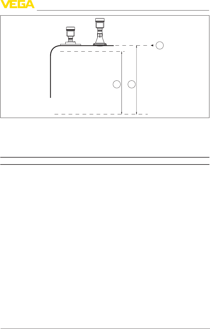
75
11 Supplement
VEGAPULS 69 • 4 … 20 mA/HART - two-wire
47247-EN-150615
2
1
3
Fig. 58: Data of the input variable
1 Reference plane
2 Measured variable, max. measuring range
3 Useablemeasuringrange(recommendedmin.distancesee"Measuringaccuracy")
Max. measuring range 120 m (393,7 ft)
Output variable
Output signal 4 … 20 mA/HART
Range of the output signal 3.8 … 20.5 mA/HART (default setting)
Signal resolution 0.3 µA
Resolution, digital < 1 mm (0.039 in)
Failure signal current output (adjustable) mA-value unchanged 20.5 mA, 22 mA, < 3.6 mA
Max. output current 22 mA
Starting current ≤3.6mA;≤10mAfor5msafterswitchingon
Load see load diagram under Power supply
Damping (63 % of the input variable),
adjustable
0 … 999 s
HART output values according to HART 7.02)
ƲPV (Primary Value) Lin. percent
ƲSV (Secondary Value) Distance
ƲTV (Third Value) Meas. reliability
ƲQV (Fourth Value) Electronics temperature
FullledHARTspecication 7.0
Further information on Manufacturer ID,
Device ID, Device Revision
See website of HART Communication Foundation
2) Default values, can be assigned individually
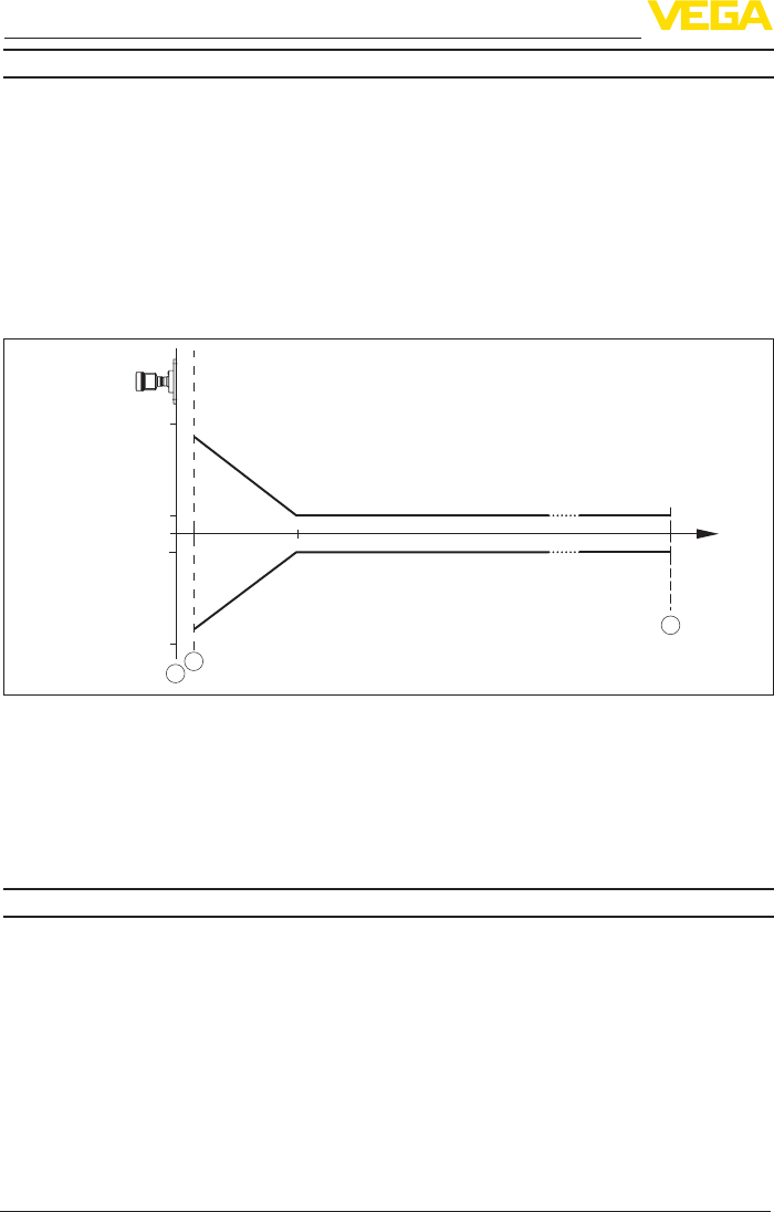
76
11 Supplement
VEGAPULS 69 • 4 … 20 mA/HART - two-wire
47247-EN-150615
Accuracy (according to DIN EN 60770-1)
Process reference conditions according to DIN EN 61298-1
ƲTemperature +18 … +30 °C (+64 … +86 °F)
ƲRelative humidity 45 … 75 %
ƲAir pressure 860 … 1060 mbar/86 … 106 kPa (12.5 … 15.4 psig)
Installation reference conditions
ƲMin. distance to internal installations > 200 mm (7.874 in)
Ʋ Reector Flatplatereector,surface1x1m(3.281x3.281ft)
Ʋ Falsereections Biggest false signal, 20 dB smaller than the useful signal
Deviation See following diagrams
1,0 m (3.281 ft)
30 mm (1.181 in)
- 30 mm (- 1.181 in)
0
5 mm (0.197 in)
- 5 mm (- 0.197 in)
1
3
0,15 m (0.49 ft)
2
Fig. 59: Deviation under reference conditions
1 Reference plane
2 Recommended min. distance
3 Measuring range end
Repeatability ≤±1mm
Deviation with bulk solids The values depend to a great extent on the application.
Bindingspecicationsarethusnotpossible.
Variablesinuencingmeasurementaccuracy
Specicationsapplytothedigitalmeasuredvalue
Temperature drift - Digital output ±3mm/10K,max.10mm
Additional deviation through electromag-
netic interference acc. to EN 61326-2-3
None
Specicationsapplyalsotothecurrentoutput
Temperature drift - Current output ±0.03%/10Krelatingtothe16mAspanmax.±0.3%
Deviation on the current output through
analogue/digital conversion
<±15µA
Additional deviation through electromag-
netic interference acc. to EN 61326-2-3
None
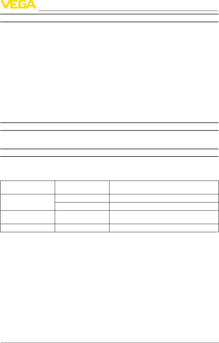
77
11 Supplement
VEGAPULS 69 • 4 … 20 mA/HART - two-wire
47247-EN-150615
Characteristics and performance data
Measuring frequency W-band(79GHztechnology)
Measuring cycle time approx. 700 ms
Step response time3) ≤3s
Beam angle4)
ƲPlastic horn antenna 3.5°
ƲMetal-jacketed lens antenna 4°
Emitted HF power (depending on the parameter adjustment)5)
ƲAverage spectral transmission power
density
-3dBm/MHzEIRP
ƲMax. spectral transmission power
density
+34dBm/50MHzEIRP
ƲMax. power density at a distance of
1 m
< 3 µW/cm²
Ambient conditions
Ambient, storage and transport tempera-
ture
-40 … +80 °C (-40 … +176 °F)
Process conditions
Fortheprocessconditions,pleasealsonotethespecicationsonthetypelabel.Thelowestvalue
always applies.
Process temperature
Seal Antenna lens Process temperature (measured on the process
tting)
FKM (SHS FPM 70C3
GLT)
PEEK -40 … +130 °C (-40 … +266 °F)
PEEK -40 … +200 °C (-40 … +392 °F)
FKM (SHS FPM 70C3
GLT)
PP -40 … +80 °C (-40 … +176 °F)
EPDM (COG AP310) PP -40 … +80 °C (-40 … +176 °F)
Ambient temperature - Process temperature
3) Time span (after a sudden measuring distance change of max. 2 m in bulk solids applications) until the output
signalhastakenon90%ofthenalvalueforthersttime(IEC61298-2).
4) Outsidethespeciedbeamangle,theenergyoftheradarsignalisreducedby50%(-3dB).
5) EIRP: Equivalent Isotropic Radiated Power.
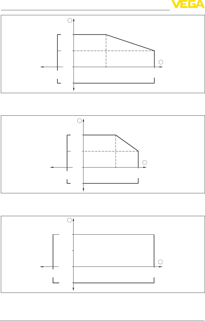
78
11 Supplement
VEGAPULS 69 • 4 … 20 mA/HART - two-wire
47247-EN-150615
1
2
0 °C
(32 °F)
-40 °C
(-104 °F)
50 °C
(122 °F)
80 °C
(176 °F)
200 °C
(392 °F)
80 °C
(176 °F)
-40 °C
(-104 °F)
Fig. 60: Ambient temperature - Process temperature, metal-jacketed lens antenna up to +200 °C (392 °F)
1 Ambient temperature
2 Process temperature
1
2
0 °C
(32 °F)
-40 °C
(-104 °F)
50 °C
(122 °F)
80 °C
(176 °F)
130 °C
(266 °F)
80 °C
(176 °F)
-40 °C
(-104 °F)
Fig. 61: Ambient temperature - Process temperature, metal-jacketed lens antenna up to +130 °C (266 °F)
1 Ambient temperature
2 Process temperature
1
2
0 °C
(32 °F)
-40 °C
(-104 °F)
80 °C
(176 °F)
80 °C
(176 °F)
-40 °C
(-104 °F)
Fig. 62: Ambient temperature - Process temperature, plastic horn antenna
1 Ambient temperature
2 Process temperature
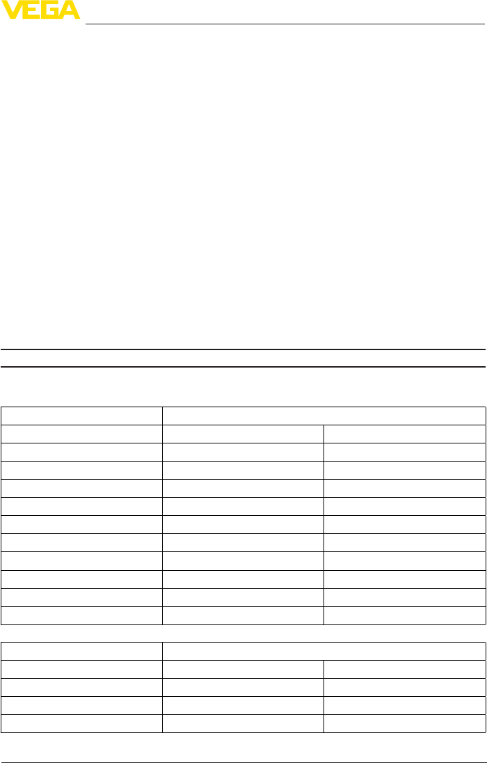
79
11 Supplement
VEGAPULS 69 • 4 … 20 mA/HART - two-wire
47247-EN-150615
Vessel pressure
Vessel pressure
ƲMetal-jacketed lens antenna -1 … 3 bar (-100 … 300 kPa/-14.5 … 43.5 psig)
ƲPlastic horn antenna -1 … 2 bar (-100 … 200 kPa/-14.5 … 29.1 psig)
ƲPlastic horn antenna - Version with
adapterangefromDN100PPor
PP-GF 30
-1 … 1 bar (-100 … 100 kPa/-14.5 … 14.5 psig)
Vesselpressurerelatingtotheange
nominal pressure stage
see supplementary instructions manual "Flanges ac-
cordingtoDIN-EN-ASME-JIS"
Mechanial stresses
Vibration resistance - Metal jacketed lens
antenna
4gat5…200HzaccordingtoEN60068-2-6(vibration
with resonance)
Vibration resistance - Plastic horn antenna
Ʋ Withadapterange 2gat5…200HzaccordingtoEN60068-2-6(vibration
with resonance)
Ʋwith mounting strap 1gat5…200HzaccordingtoEN60068-2-6(vibration
with resonance)
Shock resistance 100 g, 6 ms according to EN 60068-2-27 (mechanical
shock)
Data on rinsing air connection
Max. permissible pressure 6 bar (87.02 psig)
Air volume, depending on pressure (recommended range)
Metal-jacketed lens antenna Air volume
Pressure Withoutreuxvalve Withreuxvalve
0.2 bar (2.9 psig) 1.7 m3/h -
0.4 bar (5.8 psig) 2.5 m3/h -
0.6 bar (8.7 psig) 2.9 m3/h 0.8 m3/h
0.8 bar (11.6 psig) 3.3 m3/h 1.5 m3/h
1 bar (14.5 psig) 3.6 m3/h 2 m3/h
1.2 bar (17.4 psig) 3.9 m3/h 2.3 m3/h
1.4 bar (20.3 psig) 4 m3/h 2.7 m3/h
1.6 bar (23.2 psig) 4.3 m3/h 3 m3/h
1.8 bar (20.3 psig) 4.5 m3/h 3.5 m3/h
2 bar (23.2 psig) 4.6 m3/h 4 m3/h
Plastic horn antenna Air volume
Pressure Withoutreuxvalve Withreuxvalve
0.2 bar (2.9 psig) 3.3 m3/h -
0.4 bar (5.8 psig) 5 m3/h -
0.6 bar (8.7 psig) 6 m3/h 1 m3/h

80
11 Supplement
VEGAPULS 69 • 4 … 20 mA/HART - two-wire
47247-EN-150615
Plastic horn antenna Air volume
Pressure Withoutreuxvalve Withreuxvalve
0.8 bar (11.6 psig) - 2.1 m3/h
1 bar (14.5 psig) - 3 m3/h
1.2 bar (17.4 psig) - 3.5 m3/h
1.4 bar (20.3 psig) - 4.2 m3/h
1.6 bar (23.2 psig) - 4.4 m3/h
1.8 bar (20.3 psig) - 4.8 m3/h
2 bar (23.2 psig) - 5.1 m3/h
Connection
ƲThread G⅛
ƲSeal with metal jacketed lens antenna Threaded plug of 316Ti
Reuxvalve-unmounted(asoptionwithnon-Exversion,includedinthescopeofdeliverywithEx
version)
ƲMaterial 316Ti
ƲThread G⅛
ƲSeal FKM (SHS FPM 70C3 GLT), EPDM (COG AP310)
ƲFor connection G¼
Ʋopening pressure 0.5 bar (7.25 psig)
ƲNominal pressure stage PN 250
Electromechanical data - version IP 66/IP 67 and IP 66/IP 68; 0.2 bar
Cable gland M20 x 1.5 or ½ NPT
Wire cross-section (spring-loaded terminals)
ƲMassive wire, stranded wire 0.2 … 2.5 mm² (AWG 24 … 14)
ƲStranded wire with end sleeve 0.2 … 1.5 mm² (AWG 24 … 16)
Electromechanical data - version IP 66/IP 68 (1 bar)
Options of the cable entry
ƲCable gland with integrated connec-
tion cable
M20 x 1.5 (cable: ø 5 … 9 mm)
ƲCable entry ½ NPT
ƲBlind plug M20 x 1.5; ½ NPT
Connection cable
ƲWire cross-section 0.5 mm² (AWG 20)
ƲWire resistance <0.036Ω/m
ƲTensile strength < 1200 N (270 lbf)
ƲStandard length 5 m (16.4 ft)
ƲMax. length 180 m (590.6 ft)
ƲMin. bending radius 25 mm (0.984 in) with 25 °C (77 °F)
ƲDiameter approx. 8 mm (0.315 in)

81
11 Supplement
VEGAPULS 69 • 4 … 20 mA/HART - two-wire
47247-EN-150615
ƲColour - Non-Ex version Black
ƲColour - Ex-version Blue
Display and adjustment module
Display element Display with backlight
Measured value indication
ƲNumber of digits 5
Ʋ Sizeofdigits W x H = 7 x 13 mm
Adjustment elements 4 keys
Protection rating
Ʋunassembled IP 20
Ʋmounted in the housing without lid IP 40
Materials
ƲHousing ABS
ƲInspection window Polyester foil
Interface to the external display and adjustment unit
Data transmission digital (I²C-Bus)
Conguration,connectioncable 4-wire, screened
Cable length max.
ƲSensors with signal output
4 … 20 mA/HART
50 m
Ʋ SensorswithsignaloutputProbus
PA, Foundation Fieldbus
25 m
Integrated clock
Date format Day.Month.Year
Time format 12 h/24 h
TimezoneExfactory CET
Rate deviation max. 10.5 min/year
Measurement electronics temerature
Resolution 0.1 °C (1.8 °F)
Accuracy ±1°C(1.8°F)
Permissible temperature range -40 … +85 °C (-40 … +185 °F)
Voltage supply
Operating voltage UB
ƲNon-Ex instrument 12 … 35 V DC
ƲEx-d instrument 12 … 35 V DC
ƲEx ia instrument 12 … 30 V DC
ƲEx-d-ia instrument 17 … 35 V DC
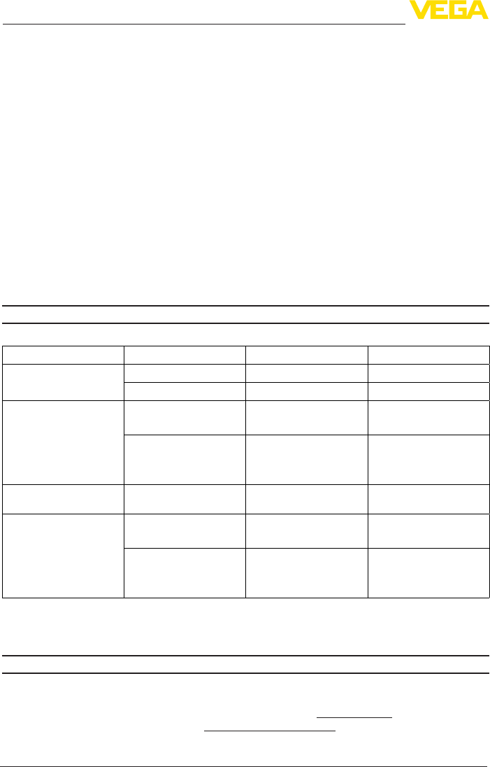
82
11 Supplement
VEGAPULS 69 • 4 … 20 mA/HART - two-wire
47247-EN-150615
Operating voltage UB - illuminated display and adjustment module
ƲNon-Ex instrument 18 … 35 V DC
ƲEx-d instrument 18 … 35 V DC
ƲEx ia instrument 18 … 30 V DC
ƲEx-d-ia instrument Due to the barrier, no lighting possible
Reverse voltage protection Integrated
Permissible residual ripple - Non-Ex, Ex-ia instrument
Ʋfor 9.6 V< UB < 14 V ≤0.7Ve(16…400Hz)
Ʋfor 18 V< UB < 36 V ≤1.0Ve(16…400Hz)
Permissible residual ripple - Ex-d-ia instrument
Ʋfor 18 V< UB < 36 V ≤1Ve(16…400Hz)
Load resistor
ƲCalculation (UB - Umin)/0.022 A
ƲExample - Non-Ex instrument with
UB= 24 V DC
(24V-12V)/0.022A=545Ω
Electrical protective measures
Protection rating
Housing material Version IP-protection class NEMA protection
Plastic Single chamber IP 66/IP 67 NEMA4X
Double chamber IP 66/IP 67 NEMA4X
Aluminium Single chamber IP 66/IP 68 (0.2 bar)
IP 68 (1 bar)
NEMA 6P
NEMA 6P
Double chamber IP 66/IP 67
IP 66/IP 68 (0.2 bar)
IP 68 (1 bar)
NEMA4X
NEMA 6P
NEMA 6P
Stainless steel, electro-
polished
Single chamber IP 66/IP 68 (0.2 bar) NEMA 6P
Stainless steel, precision
casting
Single chamber IP 66/IP 68 (0.2 bar)
IP 68 (1 bar)
NEMA 6P
NEMA 6P
Double chamber IP 66/IP 67
IP 66/IP 68 (0.2 bar)
IP 68 (1 bar)
NEMA4X
NEMA 6P
NEMA 6P
Overvoltage category III (IEC 61010-1)
Protection class III (IEC 61010-1)
Approvals
Instrumentswithapprovalscanhavedierenttechnicalspecicationsdependingontheversion.
For that reason the associated approval documents of these instruments have to be carefully
noted. They come with the delivery or can be downloaded under www.vega.com, "VEGATools"
and "Instrument search" as well as under www.vega.com/downloads and "Approvals".
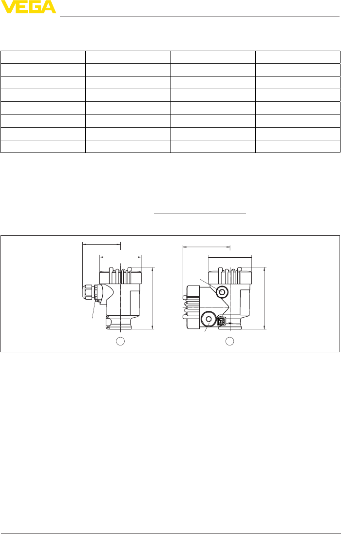
83
11 Supplement
VEGAPULS 69 • 4 … 20 mA/HART - two-wire
47247-EN-150615
11.2 Radio astronomy stations
The following table shows the geographic position of the radio astronomy stations in Europe:
Country Name of the Station Geographic Latitude Geographic Longitude
Finland Metsähovi 60°13'04'' N 24°23'37'' E
France Plateau de Bure 44°38'01'' N 05°54'26'' E
Germany Eelsberg 50°31'32'' N 06°53'00'' E
Italy Sardinia 39°29'50" N 09°14'40" E
Spain Yebes 40°31'27" N 03°05'22" W
Pico Veleta 37°03'58" N 03°23'34" W
Sweden Onsala 57°23’45" N 11°55’35" E
1 Frequencyband:75GHzto85GHz
11.3 Dimensions
The following dimensional drawings represent only an extract of all possible versions. Detailed
dimensional drawings can be downloaded at www.vega.com/downloads under "Drawings".
Plastic housing
~ 69 mm
(2.72")
ø 79 mm
(3.11")
112 mm
(4.41")
M20x1,5/
½ NPT
~ 84 mm
(3.31")
M16x1,5
112 mm
(4.41")
M20x1,5/
½ NPT
12
ø 79 mm
(3.11")
Fig.63:HousingversionswithprotectionratingIP66/IP68(0.2bar)-withintegrateddisplayandadjustment
modulethehousingis9mm/0.35inhigher
1 Single chamber version
2 Double chamber version
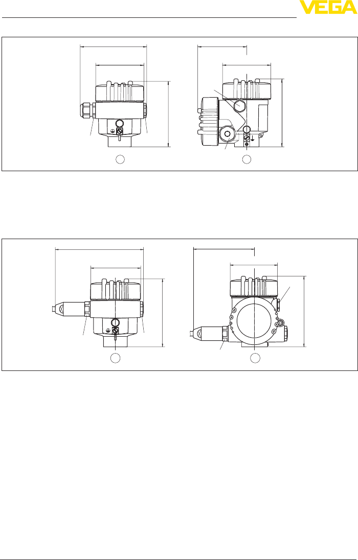
84
11 Supplement
VEGAPULS 69 • 4 … 20 mA/HART - two-wire
47247-EN-150615
Aluminium housing
21
ø 86 mm
(3.39")
~ 116 mm
(4.57")
116 mm
(4.57")
M20x1,5
M20x1,5/
½ NPT
~ 87 mm
(3.43")
M16x1,5
ø 86 mm
(3.39")
120 mm
(4.72")
M20x1,5/
½ NPT
Fig.64:HousingversionswithprotectionratingIP66/IP68(0.2bar)-withintegrateddisplayandadjustment
modulethehousingis9mm/0.35inhigher
1 Single chamber version
2 Double chamber version
Aluminium housing with protection rating IP 66/IP 68 (1 bar)
120 mm
(4.72")
~ 105 mm
(4.13")
116 mm
(4.57")
~ 150 mm
(5.91")
ø 86 mm
(3.39")
ø 86 mm
(3.39")
M20x1,5/
½ NPT
M16x1,5
2
M20x1,5
M20x1,5
1
Fig.65:HousingversionwithprotectionratingIP66/IP68(1bar)-withintegrateddisplayandadjustmentmodule
thehousingis9mm/0.35inhigher
1 Single chamber version
2 Double chamber version
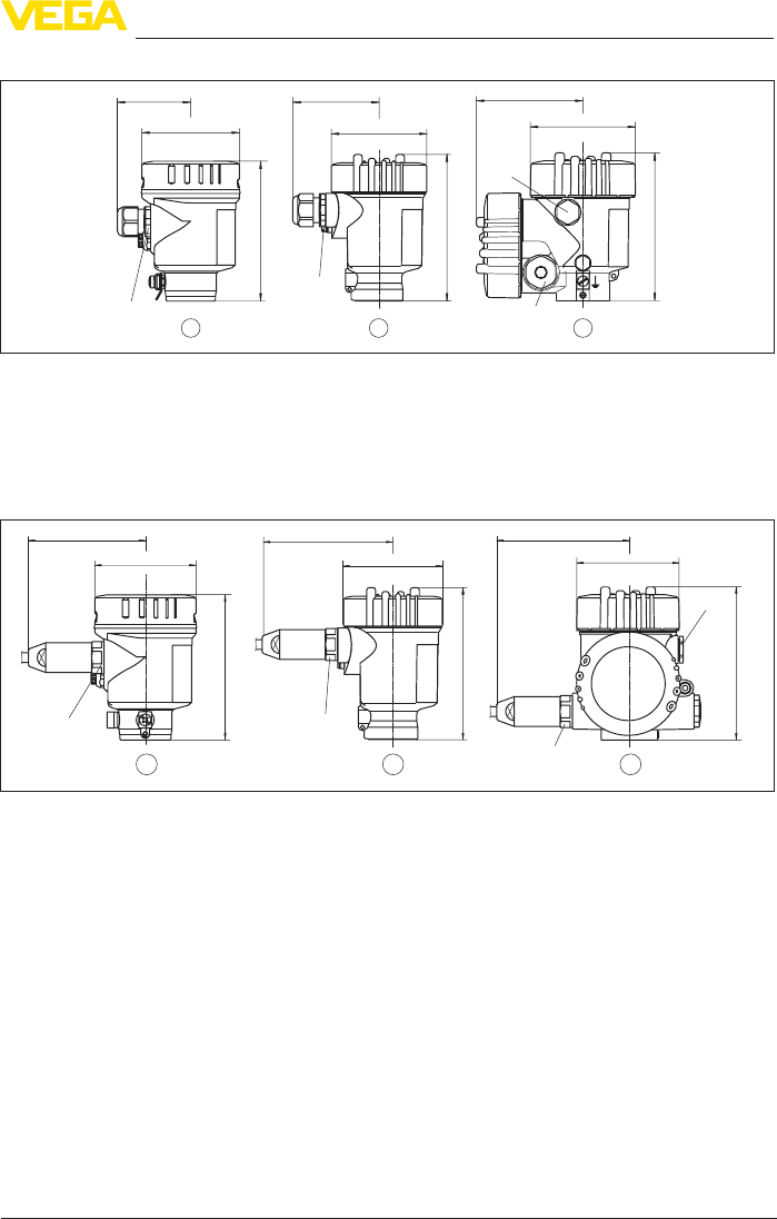
85
11 Supplement
VEGAPULS 69 • 4 … 20 mA/HART - two-wire
47247-EN-150615
Stainless steel housing
~ 69 mm
(2.72")
ø 79 mm
(3.11")
117 mm
(4.61")
M20x1,5/
½ NPT
~ 59 mm
(2.32")
ø 80 mm
(3.15")
112 mm
(4.41")
M20x1,5/
½ NPT
~ 87 mm
(3.43") ø 86 mm
(3.39")
120 mm
(4.72")
M20x1,5/
½ NPT
M16x1,5
321
Fig.66:HousingversionswithprotectionratingIP66/IP68(0.2bar)-withintegrateddisplayandadjustment
modulethehousingis9mm/0.35inhigher
1 Single chamber version, electropolished
2 Single chamber version, precision casting
3 Double chamber version, precision casting
Stainless steel housing with protection rating IP 66/IP 68, 1 bar
117 mm
(4.61")
~ 103 mm
(4.06") ø 79 mm
(3.11")
120 mm
(4.72")
~ 105 mm
(4.13") ø 86 mm
(3.39")
M20x1,5
M20x1,5/
½ NPT
M16x1,5
~ 93 mm
(3.66") ø 80 mm
(3.15")
112 mm
(4.41")
M20x1,5/
½ NPT
3
21
Fig.67:HousingversionwithprotectionratingIP66/IP68(1bar)-withintegrateddisplayandadjustmentmodule
thehousingis9mm/0.35inhigher
1 Single chamber version, electropolished
2 Single chamber version, precision casting
3 Double chamber version, precision casting
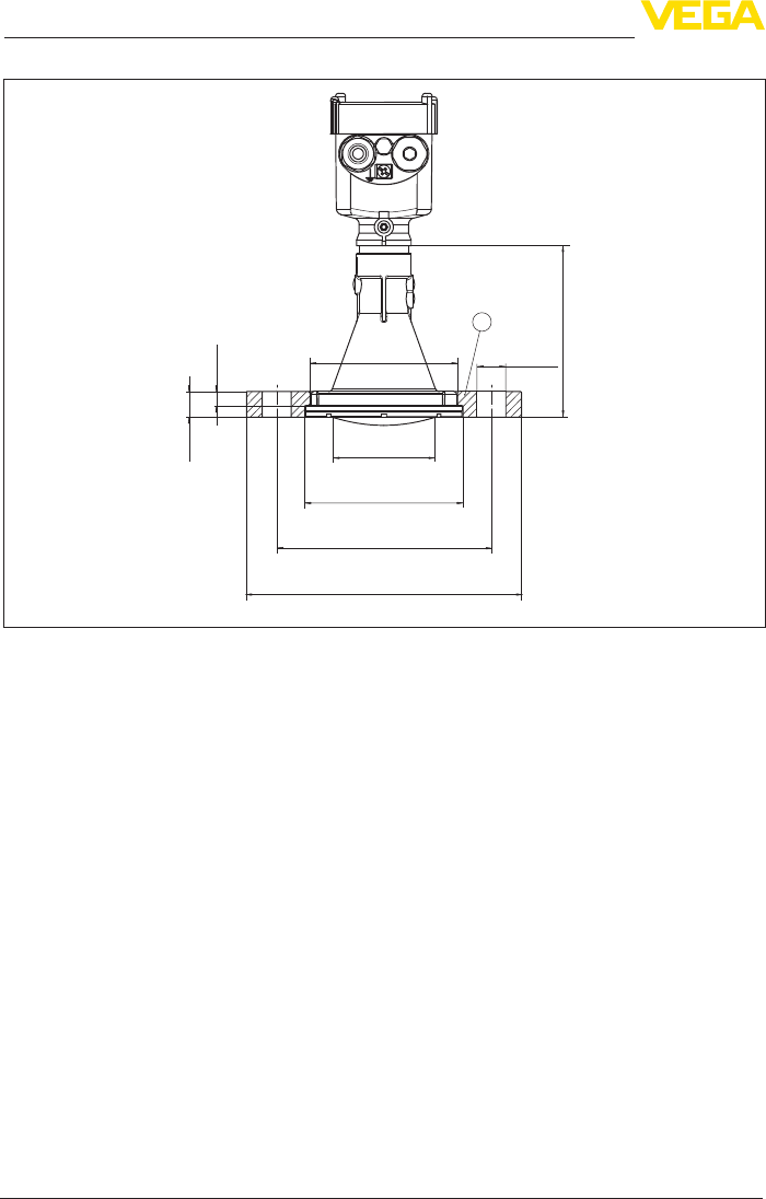
86
11 Supplement
VEGAPULS 69 • 4 … 20 mA/HART - two-wire
47247-EN-150615
Radarsensorwithcompressionange
126 mm
(4.96")
10,5 mm
(0.41")
19 mm
(0.75")
ø 75 mm
(2.95")
ø 115 mm
(4.53")
ø 156 mm
(6.14")
ø 200 mm
(7.87")
ø 21 mm
(0.83")
ø 107 mm
(4.21")
1
Fig.68:Radarsensorwithcompressionange
1 Compressionange
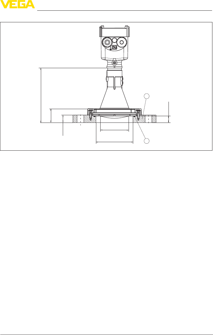
87
11 Supplement
VEGAPULS 69 • 4 … 20 mA/HART - two-wire
47247-EN-150615
Radarsensorwithadapterange
2
1
144 mm
(5.67")
36,5 mm
(1.44")
20 mm
(0.79")
17,5 mm
(0.69")
ø 75 mm
(2.95")
ø 98 mm
(3.86")
Fig.69:Radarsensorwithadapterange
1 Adapterange
2 Process seal
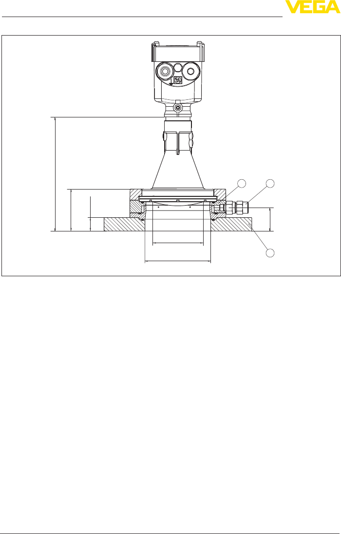
88
11 Supplement
VEGAPULS 69 • 4 … 20 mA/HART - two-wire
47247-EN-150615
Radarsensorwithadapterangeandrinsingairconnection
3
21
170 mm
(6.69")
62,5 mm
(2.46")
20 mm
(0.79")
34,7 mm
(1.37")
ø 75 mm
(2.95")
ø 98 mm
(3.86")
Fig.70:VEGAPULS69,adapterangeandrinsingairconnection
1 Rinsing air connection
2 Reuxvalve
3 Adapterange
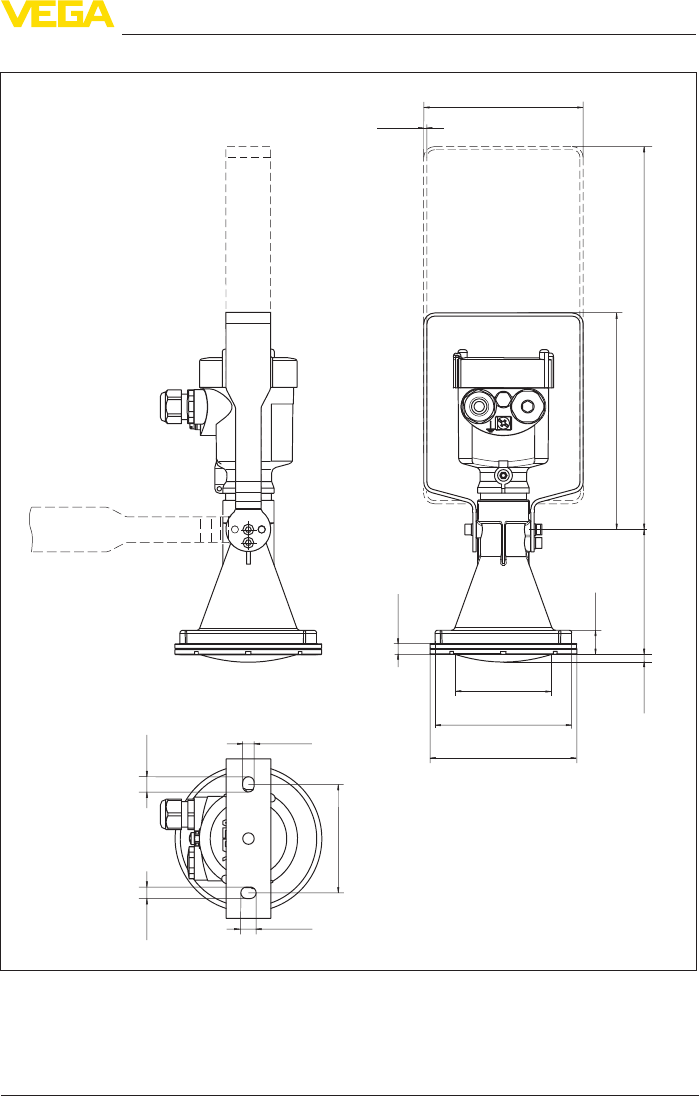
89
11 Supplement
VEGAPULS 69 • 4 … 20 mA/HART - two-wire
47247-EN-150615
VEGAPULS 69, plastic horn antenna with mounting strap
125 mm
(4.92")
2,5 mm
(0.10")
ø 75 mm
(2.95")
ø 107 mm
(4.21")
ø 115 mm
(4.53")
300 mm
(11.81")
19 mm
(0.75")
98 mm
(3.86")
6 mm
(0.24")
8,5 mm
(0.34")
9 mm
(0.35")
85 mm
(3.35")
12 mm
(0.47")
9 mm
(0.35")
12 mm
(0.47")
170 mm
(6.69")
Fig.71:VEGAPULS69,plastichornantenna,mountingstrapin170or300mmlength
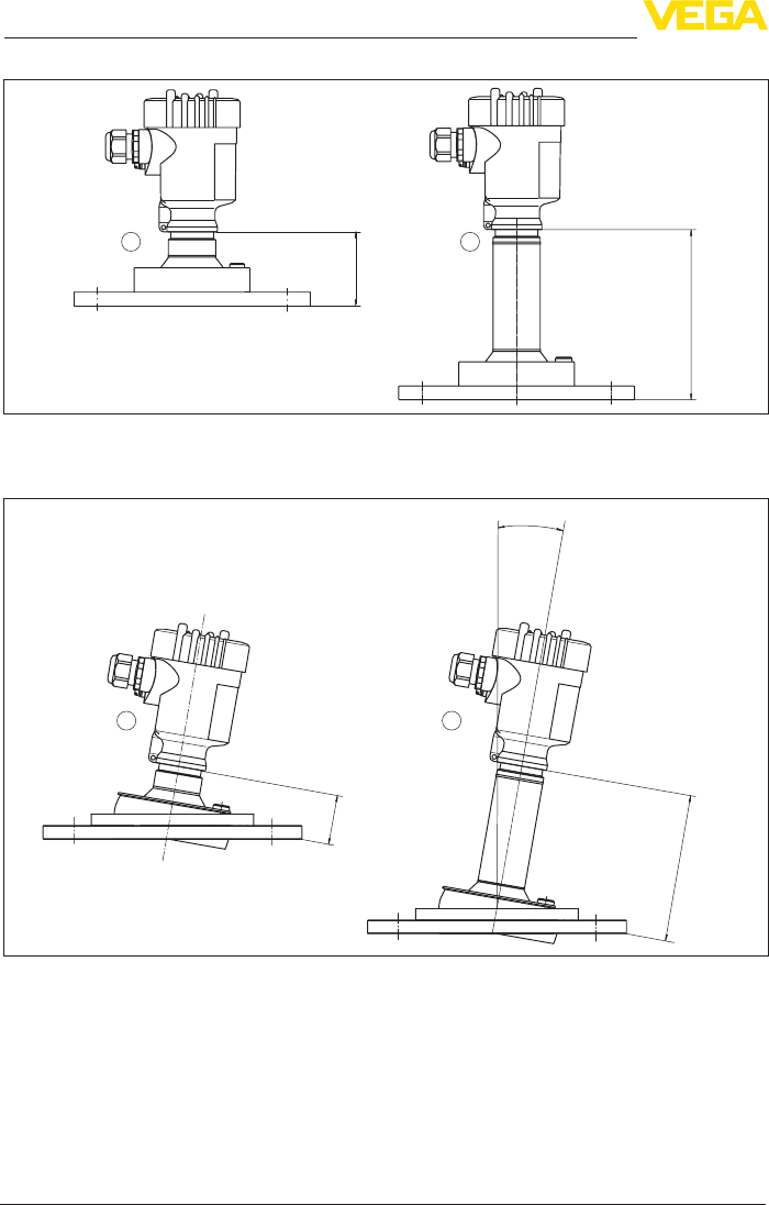
90
11 Supplement
VEGAPULS 69 • 4 … 20 mA/HART - two-wire
47247-EN-150615
VEGAPULS 69, metal-jacketed lens antenna
21
144 mm
(5.67")
63 mm
(2.48")
Fig.72:VEGAPULS69,metal-jacketedlensantennainangeversion
VEGAPULS 69, metal-jacketed lens antenna and swivelling holder
max. 10°
144 mm
(5.67")
63 mm
(2.48")
21
Fig.73:VEGAPULS69,metal-jacketedlensantennaandswivellingholder

91
11 Supplement
VEGAPULS 69 • 4 … 20 mA/HART - two-wire
47247-EN-150615
11.4 Industrial property rights
VEGA product lines are global protected by industrial property rights. Further information see
www.vega.com.
Only in U.S.A.: Further information see patent label at the sensor housing.
VEGA Produktfamilien sind weltweit geschützt durch gewerbliche Schutzrechte.
Nähere Informationen unter www.vega.com.
Les lignes de produits VEGA sont globalement protégées par des droits de propriété intellec-
tuelle. Pour plus d'informations, on pourra se référer au site www.vega.com.
VEGA lineas de productos están protegidas por los derechos en el campo de la propiedad indus-
trial. Para mayor información revise la pagina web www.vega.com.
Линии продукции фирмы ВЕГА защищаются по всему миру правами на интеллектуальную
собственность. Дальнейшую информацию смотрите на сайте www.vega.com.
VEGA系列产品在全球享有知识产权保护。
进一步信息请参见网站<www.vega.com。
11.5 Trademark
All the brands as well as trade and company names used are property of their lawful proprietor/
originator.

92
INDEX
VEGAPULS 69 • 4 … 20 mA/HART - two-wire
47247-EN-150615
INDEX
A
Adjustment 47, 48
Adjust the current output 54
C
Change the language 49
Check output signal 68
Connecting
– Electrically 30
– To the PC 59
Connection
– Cable 29
– Steps 30
– Technology 30
Copy sensor settings 53
Current output 48
Current output Min./Max. 49
Curve indication
– Echo curve 50
D
Damping 48
Date/Time 51
Default values 52
Deviation 68
Display lighting 50
E
Echo curve memory 63
Echo curve of the setup 51
EDD (Enhanced Device Description) 62
Electronics and terminal compartment, single
chamber housing 32
Error codes 66
Event memory 63
F
False signal suppression 54
Faultrectication68
Functional principle 10
G
Grounding 29
H
HART
– Resistor 59
HART address 56
L
Linearization56
Lock adjustment 49
M
Main menu 43
Measured value memory 63
Measurement loop name 44
Mounting
– Flange 16
– Strap 14
N
NAMUR NE 107 65, 67
O
Operation
– System 41
P
Peak value indicator 50
Polarisation 18
R
Repair 72
Reset 52
S
Sensor status 50
Service hotline 71
Set display parameters 50
Setup
– Quick setup 42
Shielding 29
Simulation 51
Socket 20
Special parameters 56
Status messages - NAMUR NE 107 64
T
Type label 9
U
Units 44
V
Vessel installations 24
Vessel insulation 25

93
Notes
VEGAPULS 69 • 4 … 20 mA/HART - two-wire
47247-EN-150615

94
Notes
VEGAPULS 69 • 4 … 20 mA/HART - two-wire
47247-EN-150615

95
Notes
VEGAPULS 69 • 4 … 20 mA/HART - two-wire
47247-EN-150615

Printing date:
VEGA Grieshaber KG
Am Hohenstein 113
77761 Schiltach
Germany
47247-EN-150615
All statements concerning scope of delivery, application, practical use and operat-
ing conditions of the sensors and processing systems correspond to the information
available at the time of printing.
Subject to change without prior notice
© VEGA Grieshaber KG, Schiltach/Germany 2015
Phone +49 7836 50-0
Fax +49 7836 50-201
E-mail: info.de@vega.com
www.vega.com