VERDANT ENVIRONMENTAL TECHNOLOGIES WX THERMOSTAT User Manual WX TW Thermostat Installation Manual
VERDANT ENVIRONMENTAL TECHNOLOGIES THERMOSTAT WX TW Thermostat Installation Manual
WX-TW-Thermostat-Installation-Manual
VX-TW
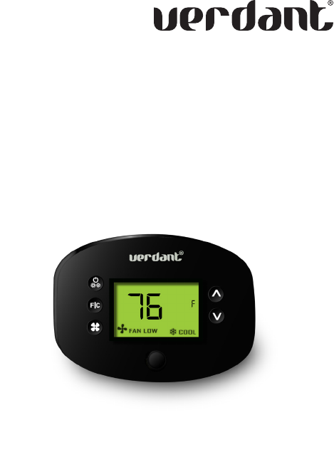
VX Series Wireless Thermostat
with an Occupancy Sensor
INSTALLATION MANUAL
V.1 JUNE 26, 2017
3
Table of Contents
Introduction .................................................................................................4
Thermostat Installation ...............................................................................6
Pairing the Thermostat and the Control Card ............................................. 7
Installing the Wireless Control Card ............................................................8
Mounting the thermostat to the wall .........................................................9
Thermostat Configuration ......................................................................... 10
Setting the thermostat clock .......................................................................11
Entering the room number ......................................................................... 12
Configuring the Equipment Settings - Compressor Type ........................... 13
Configuring the Equipment Settings - Electric Heat ..................................14
Configuring the Equipment Settings - Reversing Valve .............................15
Configuring the Energy Saving Settings ....................................................16
Testing the thermostat ............................................................................... 17
Thermostat Maintenance ............................................................................18
Replacing Thermostat Batteries .................................................................18
Troubleshooting ..........................................................................................19
Error Codes ..................................................................................................19
Thermostat is not controlling the HVAC unit. .......................................... 20
APPENDIX 1 - Energy Saving Presets ...........................................................21
APPENDIX 2 - Glossary ................................................................................ 22
Warranty Information ................................................................................ 23
Technical Specifications ............................................................................. 24

4 5
Introduction
Verdant VX Series Energy Management Thermostats for the hospitality
industry deliver unprecedented energy savings without compromising
guest comfort.
An integrated occupancy sensor uses a combination of motion and
thermal sensing technologies for accurate occupancy detection.
Reliable occupancy detection allows for energy savings when rooms are
unoccupied.
Energy saving presets eliminate the guesswork and make it easy to
adjust the energy saving settings. (Patent Pending)
Fully configurable energy saving settings allow for customization of the
thermostat energy saving settings to fit any situation.
Large buttons with international symbols make it easy to adjust the
temperature in ±1° °F or °C and control the fan speed.
Comprehensive configuration options ensure full compatibility with
virtually any existing or emerging hospitality HVAC system with up to 2
heat and 1 cool stages.
Built-in wireless mesh-networking enables optional remote management.
NOTICE
FOR INSTALLATION OF NETWORKING THERMOSTATS WITH
REMOTE MANAGEMENT, REFER TO THE “VX-TW NETWORK
INSTALLATION” MANUAL.
LOGIN TO THE REMOTE MANAGEMENT WEBSITE TO CONFIRM
THE SERVER IS CONNECTED TO THE INTERNET BEFORE
INSTALLING THERMOSTATS.
DO NOT INSTALL THERMOSTATS IF THE SERVER IS NOT
CONNECTED TO THE INTERNET. STOP THE INSTALLATION AND
CONTACT VERDANT TECHNICAL SUPPORT.
START BY FIRST INSTALLING A THERMOSTAT IN THE ROOM
CLOSEST TO THE SERVER.
LOG IN TO VERDANT’S REMOTE MANAGEMENT WEBSITE
TO CONFIRM THAT THE THERMOSTAT IS ON THE REMOTE
MANAGEMENT WEBSITE WITH THE CORRECT ROOM NUMBER.
CONTINUE BY INSTALLING ADDITIONAL THERMOSTATS IN
ADJACENT ROOMS ONLY AFTER CONFIRMING THAT INSTALLED
THERMOSTAT(S) HAVE CONNECTED TO THE WIRELESS NETWORK
AND THE REMOTE MANAGEMENT WEBSITE .
IF INSTALLED THERMOSTAT(S) ARE NOT CONNECTING TO THE
NETWORK AND DO NOT APPEAR ON THE VERDANT’S REMOTE
MANAGEMENT WEBSITE WITH THE CORRECT ROOM NUMBER,
STOP THE INSTALLATION AND CONTACT VERDANT TECHNICAL
SUPPORT
THE ROOMS FURTHEST AWAY FROM THE SERVER SHOULD BE
INSTALLED LAST.
6 7
Before You Begin
➤Determine the appropriate installation location for the thermostat.
➤Set the HVAC unit to “External Thermostat” (Class 2) mode. Consult
the HVAC unit documentation to determine how to set the HVAC
unit to “External Thermostat” mode.
➤Consult HVAC manufacturer’s documentation or use a voltmeter to
determine if the HVAC unit outputs AC or DC power (24V).
If the HVAC unit outputs AC power, make sure that the jumper
on the Wireless Control Card is in the AC position - jumper is
connecting “R” and “COM” pins (Default).
If the HVAC unit outputs DC power, make sure that the jumper
on the Wireless Control Card is in the DC position - jumper is
connecting “COM” and “C” pins.
THE THERMOSTAT SHOULD FACE THE BED AREA OF THE ROOM.
THE THERMOSTAT AND CONTROL CARD MUST NOT BE
INSTALLED NEAR OR ON METAL STRUCTURES OR SURFACES
INCLUDING METAL AIR DUCTING THAT MAY BE IN THE WALL.
WIRELESS CONTROLS CARDS MUST BE MOUNTED AWAY FROM
METAL AND METAL ENCLOSURES. VTAC INSTALLATIONS
SHOULD MOUNT THE CONTROL CARD ABOVE THE UNIT’S METAL
ENCLOSURE.
METAL STRUCTURES AND SURFACES SIGNIFICANTLY REDUCE
THE RANGE OF THE WIRELESS SIGNAL.
Before You Begin
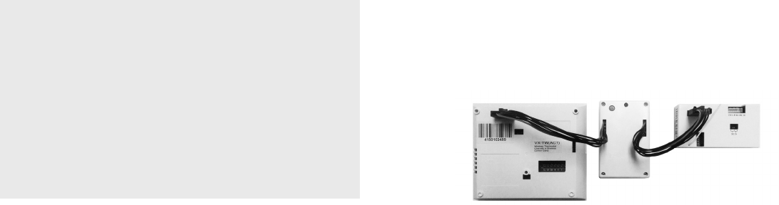
Pairing the Thermostat and the Control Card
The Thermostat and Control Card must be paired in order to operate
together. Once paired, the thermostat cannot be used with another
wireless control card without repeating the pairing procedure.
In case of Network Installation with Remote Management, the
thermostat and the Control Card must be paired with a Network
Programmer specific to the property before the installation.
The Thermostat and Control Card must not be powered during the
pairing procedure - remove batteries from the thermostat and unplug the
control card from the HVAC unit during the pairing procedure.
➤Plug one programmer connector into the thermostat;
➤Plug the other programmer connector into the control card;
➤Push the black button on the programmer. The red light on the
programmer should turn on and remain steadily lit;
If the red light on the programmer is blinking or is not steadily lit,
unplug the programmer from the thermostat and the control card
and repeat the steps above.
➤Unplug the programmer from the thermostat and the control card;

8 9
Thermostat Installation
NOTE: If the PTAC unit has only one (1) fan speed, connect both fan
control wires – Green and Purple – to the fan terminal (G).
Wiring Table - 24V AC
Wire
Color Terminal
Letter Terminal
Connection
Black C Common
Red R 24V
Yellow Y Compressor
White W Heat
Orange O or B Reverse Valve
Green GH Fan High
Purple GL Fan Low
Wiring Table - 24V DC
Wire
Color Terminal
Letter Terminal
Connection
Black R 24V
Red C Common
Yellow Y Compressor
White W Heat
Orange O or B Reverse Valve
Green GH Fan High
Purple GL Fan Low
Installing the Wireless Control Card
➤Power Off the HVAC unit;
➤Connect the control card to the thermostat terminals on the HVAC
unit - refer to the Wiring Table to determine proper connections.
➤Mount the control card inside of the HVAC unit.
THE WIRELESS CONTROL CARD ANTENNA MUST NOT BE TOUCHING
ANY METAL COMPONENTS OF THE HVAC UNIT.
THE WIRELESS CONTROL CARD ANTENNA MUST FACE THE
THERMOSTAT ON THE WALL AND BE ORIENTED SO THAT ANY
METAL PARTS OF THE HVAC UNIT DO NOT OBSTRUCT THE WIRELESS
COMMUNICATION TO THE THERMOSTAT AND, IN CASE OF A
NETWORK INSTALLATION, TO OTHER WIRELESS CONTROL CARDS
AND THE SERVER.
THE WIRELESS CONTROL CARD MUST NOT BE PLACED IN THE HVAC
UNIT CONDENSATION PAN AND MUST BE MOUNTED SO IT CANNOT
FALL INTO THE HVAC UNIT CONDENSATION PAN.
➤Power On the HVAC unit.
Mounting the thermostat to the wall
➤Remove the thermostat cover;
➤Use the supplied wall anchors and mounting screws to secure the
thermostat to the wall;
➤Insert two (2) AA-cell batteries (not supplied) into the thermostat
battery compartment;
➤Follow the “Thermostat Configuration” instructions;
➤Replace the thermostat cover and screw in the locking screw;
Thermostat Installation
CONFIGURATION
BUTTON
NOTE: You can access Thermostat
Configuration settings at any time by
pressing the “Configuration” button.
10 11
Thermostat Configuration
Once the thermostat is powered, thermostat configuration settings will
appear on the thermostat screen.
In order to properly operate the HVAC unit:
➤Set the thermostat clock;
➤Enter the room number;
➤Configure the equipment settings;
➤Select Energy Savings Preset;
The thermostat configuration screens have a 30-second time-out. If
no action is taken within three (30) seconds, the thermostat will exit
configuration settings.
NOTE: If the thermostat is connected to a network, the equipment
and the energy saving settings configured on the thermostat will
be ignored and the settings configured on the Remote Management
Website will be applied.
Thermostat Configuration
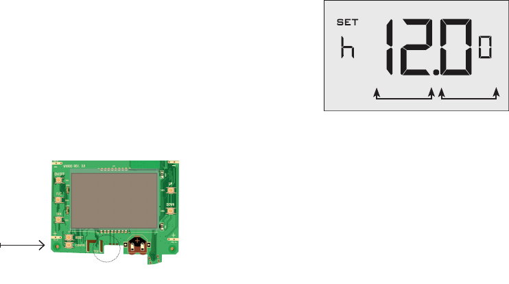
Setting the thermostat clock
Set the thermostat clock to current time in 24h (Military Time) format.
➤Use the “Up” and “Down” buttons to set the hours;
➤Press the “Fan” button to advance to the minutes setting;
➤Use the “Up” an “Down” buttons to set the minutes;
➤Press the “F/C” button to advance to the next menu;
Setting the clock correctly is crucial for proper operation of the
thermostat.
HOURS MINUTES
12 13
Thermostat Configuration
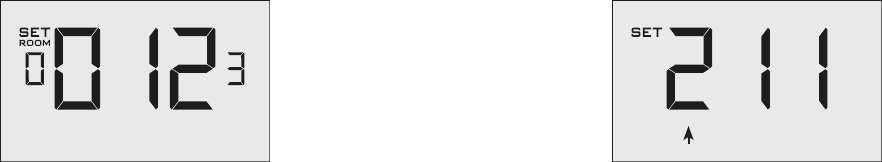
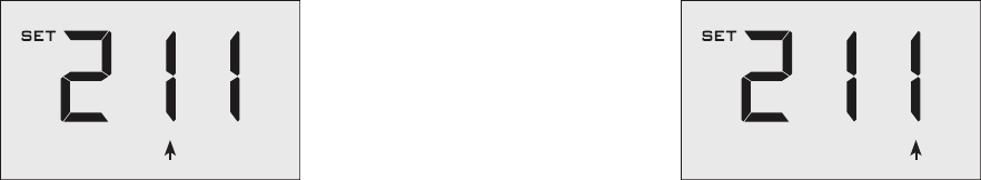
Entering the room number
Enter the room number by changing the digits on the screen. Leading
zeros “0” preceding other digits will be ignored, i.e. Room number “123”
should be entered as “00123”.
➤Use the “Up” and “Down” buttons to change the digit;
➤Press the “Fan” button advance to the next digit;
➤Press the “F/C” button to advance to the next menu;
Entering the room number correctly is crucial for proper operation of
remotely managed thermostats.
Thermostat Configuration
Configuring the Equipment Settings - Compressor Type
➤Use the “Up” and “Down” buttons to change the compressor type by
changing the first digit;
0 No Compressor
1 Heat Pump
2* Air Conditioner
➤Press the “Fan” button to advance to the next setting;
* Indicates default setting;
COMPRESSOR TYPE
14 15
Thermostat Configuration
Configuring the Equipment Settings - Electric Heat
➤Use the “Up” and “Down” buttons to change the Electric Heat setting
by changing the second digit;
0 No Electric Heat
1 * Electric Heat
➤Press the “Fan” button to advance to the next setting;
* Indicates default setting;
ELECTRIC HEAT
Thermostat Configuration
Configuring the Equipment Settings - Reversing Valve
➤Use the “Up” and “Down” buttons to change the Reversing Valve
setting by changing the third digit;
0 OB contact is energized to cool;
1 * OB contact is energized to heat;
Refer to the HVAC unit documentation to determine the
correct OB VALVE setting.
If the incorrect OB VALVE Setting is selected, the HVAC unit
will turn on the heating when air conditioning is requested
and turn on the air conditioning when heating is requested;
➤Press the “Fan” button to advance to the next setting;
➤Press the “F/C” button to advance to the next menu;
* Indicates default setting;
REVERSING VALVE
16 17
Thermostat Configuration
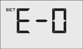
Configuring the Energy Saving Settings
➤Use the “Up” and “Down” buttons to select the Energy Saving preset:
E-0* Energy Savings Off - No Temperature Setback;
E-1 Lowest Energy Savings;
E-2 Lower Energy Savings;
E-3 Standard Energy Savings;
E-4 Higher Energy Savings;
E-5 Highest Energy Savings;
Refer to the APPENDIX 1 for Energy Saving Preset details.
E-C Indicates “Custom Energy Savings Settings” in case the active
thermostat savings settings differ from any Energy Saving preset;
For details, refer to the “Custom Energy Savings Settings” section;
➤Press the “Power” button to save the Thermostat Configuration and
start using the thermostat;
* Indicates default setting;
Testing the thermostat
Following the thermostat configuration, test if the thermostat is controlling
the HVAC unit.
➤Press the “Power” button to turn the thermostat ON;
➤Press the “Down” button to change the temperature set point below
the current room temperature to confirm that the thermostat
initiates air conditioning.
➤Press the “Up” button to change the temperature set point above
the current room temperature to confirm that the thermostat
initiates heating.
➤Change the fan speed by touching the “Fan” button to test if the
thermostat is controlling the fan speed.
Thermostat Configuration
18 19
Thermostat Maintenance
Replacing Thermostat Batteries
The low battery indicator will be displayed on the thermostat screen
when it is necessary to replace batteries in the thermostat.
Under normal operating conditions, new brand-name alkaline batteries
will last for a period of approximately one (1) year.
Please replace batteries every twelve (12) months to ensure continuous
thermostat operation.
To replace thermostat batteries:
➤Unscrew the fixing screw and remove the thermostat cover;
➤Replace the two (2) AA-cell batteries (not-supplied);
➤Replace the thermostat cover and screw in the fixing screw;
➤Follow the “Thermostat Configuration” instructions to set the
thermostat clock;
➤Press the “Power” button to start using the thermostat;
NOTE: The thermostat maintains all the “Thermostat Configuration”
settings in a non-volatile memory. There is no need to configure the
thermostat again after battery replacement.
Error Codes
ERR 1 Thermostat Temperature Sensor Hardware Defect
ERR 2 Thermostat Radio Hardware Defect
ERR 3 Thermostat Radio Software Defect
ERR 4 No link with the Wireless Control Card
ERR 5 Thermostat Memory Defect
Troubleshooting

20 21
The Thermostat is not controlling the HVAC unit.
Check if the HVAC unit is set to “External Thermostat” (Class 2) mode.
Verify the status of the red light on the Wireless Control Card;
➤The red light is off
The Wireless Control Card is not powered. Verify that the Wireless
Control Card is properly wired to the HVAC unit - specifically make
sure that the RED and the BLACK wires are properly connected;
➤If the red light is blinking with one (1) flash
The Wireless Control Card is powered but it is not communicating
with the thermostat, turn the thermostat off and on to re-initiate
the linking procedure.
In case of a Network Installation, re-link the thermostat and the
Wireless Control Card with the Network Programmer.
➤The red light is blinking with three (3) flashes.
The Wireless Control Card is communicating with the thermostat.
Verify that the Wireless Control Card is properly wired to the HVAC
unit and that equipment settings on a thermostat - compressor
type, electric heat and reversing valve - are properly configured.
Troubleshooting APPENDIX 1 - Energy Saving Presets
SCREEN
NUMBER
Level
0
Level
1
Level
2
Level
3
Level
4
Level
5
1Fan Control Mode AUTO AUTO AUTO AUTO AUTO AUTO
21st Stage Differential Heat 0.5 0.5 0.5 0.5 0.5 0.5
32nd Stage Differential Heat 11 1 2 2 2
41st Stage Differential Cool 0.5 0.5 0.5 0.5 0.5 0.5
5
Guest Occupancy Threshold
055555
6Night Occupancy Threshold 111111
7Force 2nd Stage Heating After 30 30 30 30 30 30
8Night Occupancy Start 18 19 20 21 22 23
9Night Occupancy End 12 11 10 9 8 7
10 Recovery Time 015 20 25 30 0
11 Recovery Temperature Heat 70 69 68 67 66 65
12 Setback Delay - Heat 030 25 20 15 10
13 Minimum Setback Temperature 67 66 65 64 63 62
14 Setback Delay - Cool 030 25 20 15 10
15 Maximum Setback Tempera- 72 74 76 78 80 82
16 Recovery Temperature Cool 71 72 73 74 75 76
17 Minimum Set point 64 64 65 66 67 68
18 Maximum Set point 82 82 80 78 76 74
19 Temperature Control Mode AUTO AUTO AUTO AUTO AUTO AUTO
20 Auto Changeover Set Point 111111
21 Auto Restore OFF ON ON ON ON ON
21 Setback Set Points OFF ON ON ON ON ON
22 Automatic Humidity Control ON ON ON ON ON ON
23 Temperature Calibration 000000

22 23
“Automatic Fan Control Mode” - fan runs only
when there is a demand for heating or cooling;
“Manual Fan Control Mode” - guest can select
between automatic or continuous fan operation;
“Minimum Set point” - minimum temperature
that a guest can request;
“Maximum Set point” - maximum temperature
that a guest can request;
“Auto Changeover Set Point Offset” - the
difference between the guest-selected set point
and the heat and cool changeover temperatures;
“1st Stage Differential - Heat” - the temperature
that the thermostat has to sense between the
automatic changeover temperature for heat and
the room temperature before a call for the 1st
stage heating is initiated;
“2nd Stage Differential - Heat” - difference
between 1st stage heating temperature and
room temperature before the 2nd stage heating
is initiated;
“1st Stage Differential - Cool” - the temperature
that the thermostat has to sense between the
automatic changeover temperature for cool and
the room temperature before a call for the 1st
stage cooling is initiated;
“Forced 2nd Stage Heating” - number of minutes
1st stage heating will run before 2nd stage
heating is automatically initiated if the guest set
point is not reached and the 2nd stage heating is
not initiated through differential settings
“Temperature Recovery Time” - the maximum
period of time allowed for restoring the
“Recovery Temperature”;
“Recovery Temperature” - the room temperature
that needs to be restored within the
“Temperature Recovery Time”;
“Maximum Setback Temperature” - the highest
room temperature allowed when thermostat is
in the setback mode;
“Minimum Setback Temperature” - the lowest
room temperature allowed when thermostat is
in the setback mode;
“Temperature Setback Delay” - the length of
time for which the room that is in the guest
occupancy mode needs to be unoccupied before
the temperature setback is initiated;
“Incidental Occupancy Threshold” - the minimum
period of time (in minutes) for which occupancy
needs to be detected in order to enter the “Guest
Occupancy” mode;
“Night Occupancy Threshold” - the minimum
period of time during the “Night Occupancy”
period for which occupancy needs to be detected
in order to enter the “Night Occupancy” mode;
“Night Occupancy Period” - The period of
time during the day during which the “Night
Occupancy” mode can be activated if occupancy
longer than the “Night Occupancy Threshold”
is detected;
“Auto Restore On” - thermostat will restore the
most recent guest settings when new occupancy
is detected;
“Auto Restore Off” - thermostat will NOT restore
the most recent guest and will remain turned off
settings when new occupancy is detected;
“Setback Set points On” - thermostat will
maintain setback temperatures when room is
unoccupied;
“Setback Set points Off” - thermostat will NOT
maintain setback temperatures when room is
unoccupied;
“Incidental Occupancy” - occupancy shorter than
the “Incidental Occupancy Threshold”;
“Guest Occupancy” - occupancy longer than the
“Incidental Occupancy Threshold”;
“Temperature Setback” - thermostat maintains
setback temperatures and not the guest set
point temperature in order to save energy;
“Night Occupancy Mode” - thermostat status
during which setback mode is disabled if
occupancy longer than “Night Occupancy
Threshold” is detected within the “Nigh
Occupancy” period;
“Automatic Temperature Changeover” -
thermostat automatically activates heating
or cooling to maintain the desired room
temperature;
“External Thermostat” (Class 2) mode - PTAC unit
setting allowing it to be controlled by a remote
thermostat;
APPENDIX 2 - Glossary Warranty Information
Hardware
Verdant Environmental Technologies Inc. (“Verdant”) warrants the original end user
(“Customer”) that new Verdant branded products will be free from defects in workmanship and
materials, under normal use, for one (1) year from the original purchase date.
Software
Verdant warrants to Customer that the Verdant thermostat software will perform in
substantial conformance to its program specifications for a period of one (1) year from the date
of the original purchase.
Exclusions
This warranty excludes (1) physical damage to the surface of the product, including cracks,
scratches or marks on the screen or outside casing; (2) damage caused by misuse, neglect,
improper installation, unauthorized attempts to open, repair, or modify the product, or any
other cause beyond the range of intended use; (3) damage caused by accident, fire, power
changes, other hazard, or Acts of God; (4) damage caused by water, liquids, or foreign chemicals
including condensation and humidity; or (5) use of the product with any device if such device
causes the problem.
Exclusive Remedies
Should a covered defect occur during the warranty period and Customer notifies Verdant,
Customer’s sole and exclusive remedy will be, at Verdant’s sole option and expense, to repair
or replace the product. Replacement products or parts may be new or reconditioned or
a comparable version of the defective item. Verdant warrants any replaced product or part
for a period of ninety (90) days from shipment, or through the end of the original warranty,
whichever is longer.
Obtaining Warranty Service
To obtain Warranty Service customer must follow Verdant’s “Warranty Service Procedure” and
request a Return Merchandise Authorization (RMA) number by filling out the RMA Request
Form on Verdant’s website.
Warranty Exclusive
THE FORGOING WARRANTIES AND REMEDIES ARE EXCLUSIVE AND IN LIEU OF ALL OTHER
WARRANTIES, EXPRESS OR IMPLIED, INCLUDING WARRANTIES OF MERCHANTABILITY,
FITNESS FOR A PARTICULAR PURPOSE, CORRESPONDENCE WITH DESCRIPTION, AND NON-
INFRINGEMENT, ALL OF WHICH ARE EXPRESSLY DISCLAIMED BY VERDANT AND ITS SUPPLIERS.
Disclaimer
NEITHER VERDANT NOR ITS SUPPLIERS SHALL BE LIABLE FOR INCIDENTAL, CONSEQUENTIAL,
INDIRECT, SPECIAL, OR PUNITIVE DAMAGES OF ANY KIND, OR FINANCIAL LOSS ARISING OUT
OF OR IN CONNECTION WITH THE SALE OR USE OF THIS PRODUCT, WHETHER BASED IN
CONTRACT, TORT (INCLUDING NEGLIGENCE) OR ANY OTHER THEORY, EVEN IF VERDANT HAS
BEEN ADVISED OF THE POSSIBILITY OF SUCH DAMAGES. VERDANT’S ENTIRE LIABILITY SHALL
BE LIMITED TO REPLACEMENT OR REPAIR OF THE PRODUCT.

ENGLISH
This device complies with Industry Canada license-exempt RSS standard(s). Operation is
subject to the following two conditions: (1) this device may not cause interference, and (2)
this device must accept any interference, including interference that may cause undesired
operation of the device.
FRENCH
Le présent appareil est conforme aux CNR d’Industrie Canada applicables aux appareils
radio exempts de licence. L’exploitation est autorisée aux deux conditions suivantes : (1)
l’appareil ne doit pas produire de brouillage, et (2) l’utilisateur de l’appareil doit accepter tout
brouillage radioélectrique subi, même si le brouillage est susceptible d’en compromettre le
fonctionnement.
Technical Specifications
Thermostat Wireless Control Card
Case Dimensions (Imperial) 4.015 x 5.5118” x 0.925” 3.875” x 2.125” x 0.75”
Case Dimensions (Metric) 102mm x 140mm x 23.5mm 98mm x 54mm x 19mm
Screen Dimensions (Imperial) 3.625" x 2.125" N/A
Screen Dimensions (Metric) 92mm x 54mm N/A
Operating Voltage
3V DC - 2 "C" Cell Batteries
24V AC/DC
Control Outputs Fan High (GH)
Fan Low (GL)
Compressor (Y)
Heat Pump (OB)
Electric Heat (W)
Occupancy Sensor Beam Width
±47° (94°) N/A
Wireless Frequency 900MHz 900MHz
Temperature Accuracy ±1°F N/A
FCC ID XEYWX XEYV8ACCC
IC 8410A-WX 8410A-V8ACCC
COVERED BY ONE OR MORE OF THE FOLLOWING PATENTS. US PATENTS: 8,369,994; 8,141,791; 7,918,406;
7,232,075; 7,185,825; 7,156,318; 7,152,806; 7,145,110; 7,050,026; 7,028,912; 6,902,117; 6,789,739; 6,786,421; 6,619,555;
6,581,846; 6,578,770; 7,838,803; 7,841,542; D556,061; D518,744; RE40,437; CANADIAN PATENTS: 2,633,113;
2,633,200; OTHER PATENTS PENDING.
Verdant Environmental Technologies, Inc. reserves the right to make changes, without notice, in design or
components. Product appearance may vary.
© Verdant Environmental Technologies, Inc. 2017.
Printed in Canada. V1 June 26, 2017
TECHNICAL SUPPORT: support@verdant.info 1-888-440-0991
THIS DEVICE COMPLIES WITH PART 15 OF THE FCC RULES. OPERATION IS SUBJECT
TO THE FOLLOWING TWO CONDITIONS: (1) THIS DEVICE MAY NOT CAUSE HARMFUL
INTERFERENCE, AND (2) THIS DEVICE MUST ACCEPT ANY INTERFERENCE RECEIVED,
INCLUDING INTERFERENCE THAT MAY CAUSE UNDESIRED OPERATION.
PURSUANT TO PART 15.21 OF THE FCC RULES, ANY CHANGES OR MODIFICATIONS TO THIS
EQUIPMENT NOT EXPRESSLY APPROVED BY VERDANT ENVIRONMENTAL TECHNOLOGIES,
INC. MAY VOID THE USER’S AUTHORITY TO OPERATE THE EQUIPMENT.