VIA Telecom ORCA-PCIE ORCA PCIe Data Card(CDMA2000 800/1900 1X RTT) User Manual ctm ets overview
VIA Telecom Inc. ORCA PCIe Data Card(CDMA2000 800/1900 1X RTT) ctm ets overview
UserManual.wiki
>
VIA Telecom
>
ORCA PCIE User Manual
User Manual
Navigation menu
Upload a User Manual
Namespaces
Wiki Guide
HTML
PDF
Info
Views
User Manual
Discussion / Help
Navigation

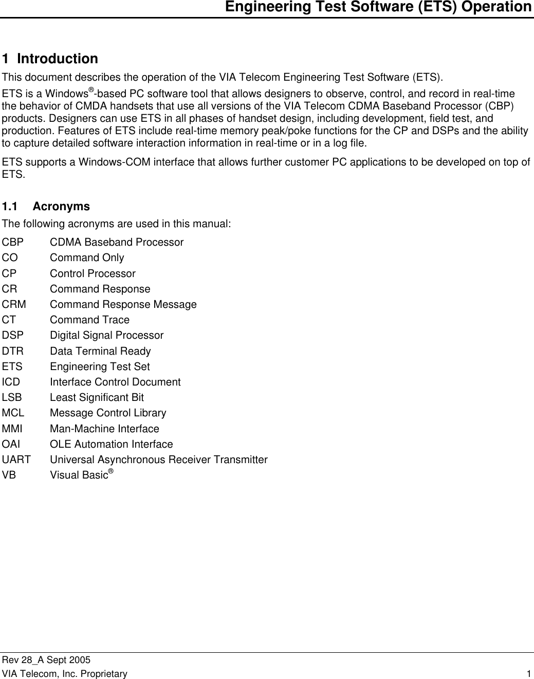
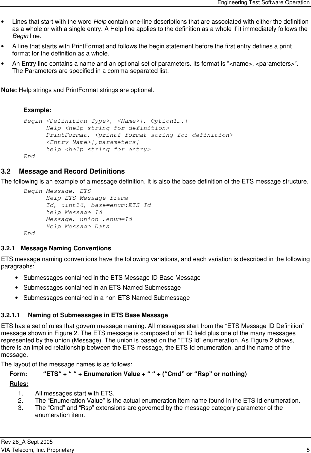
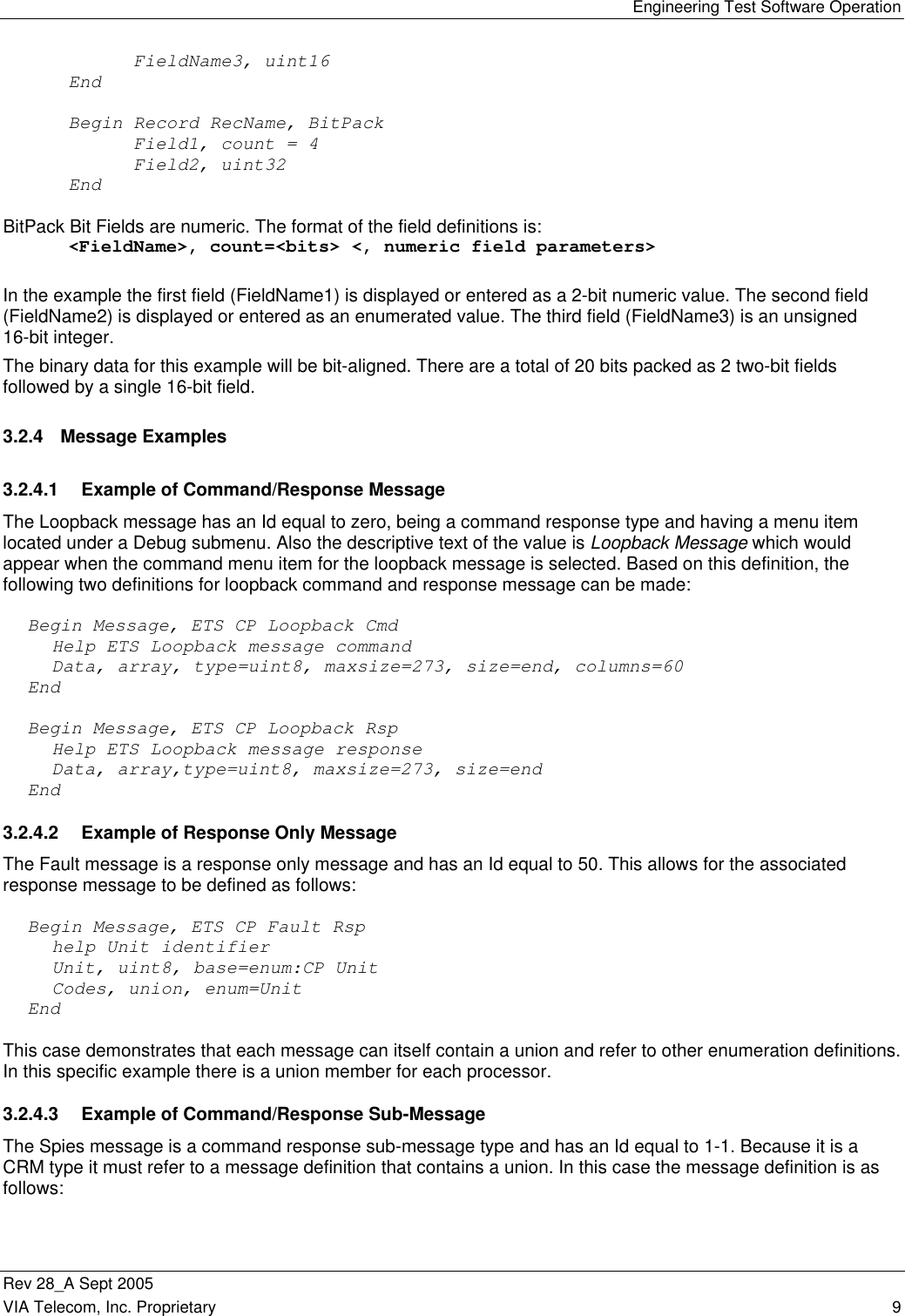
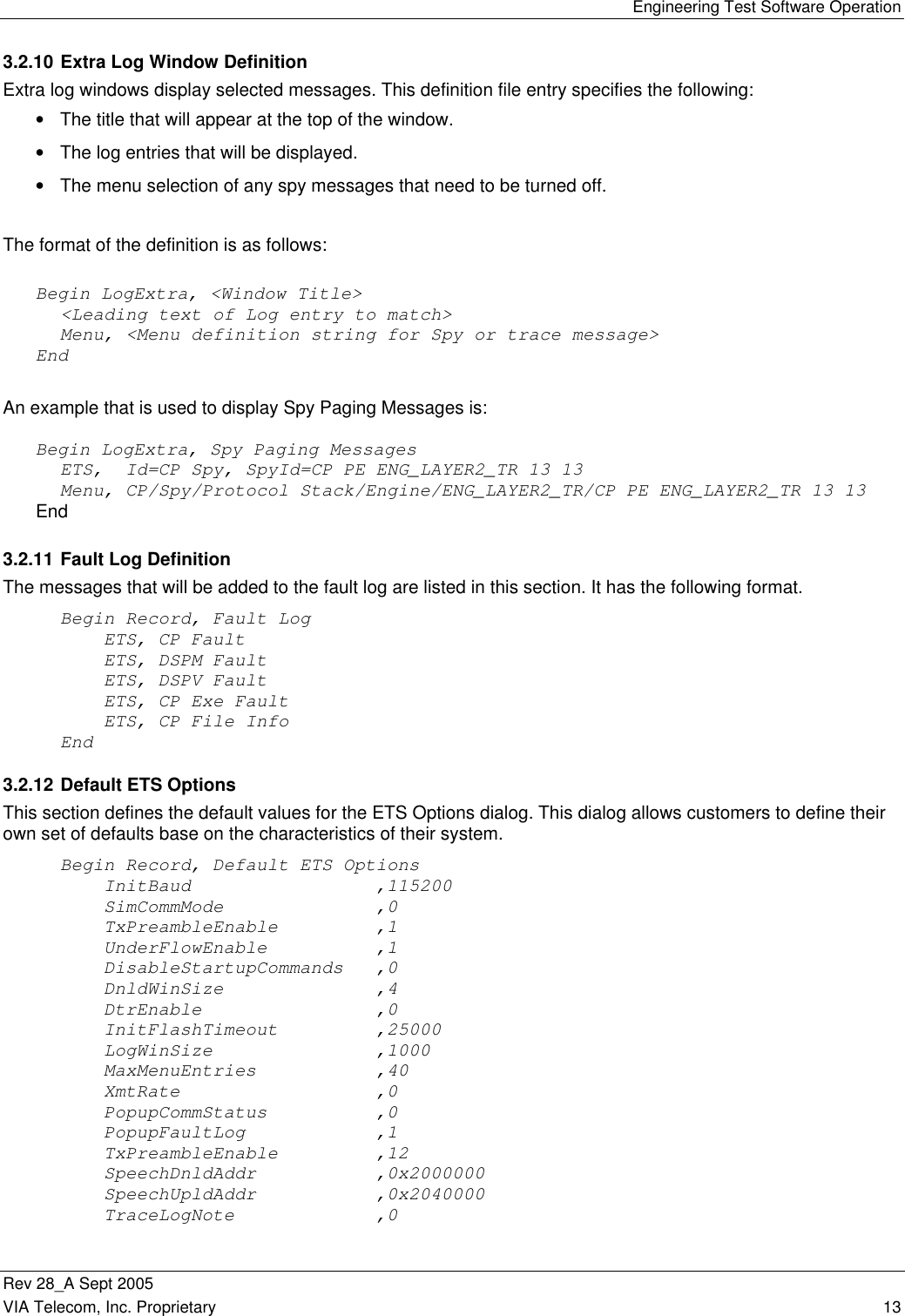
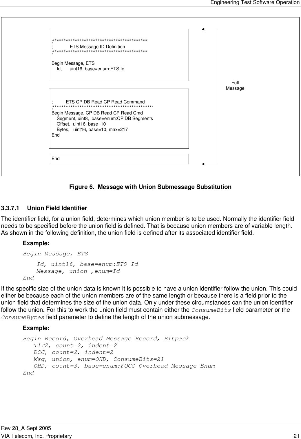
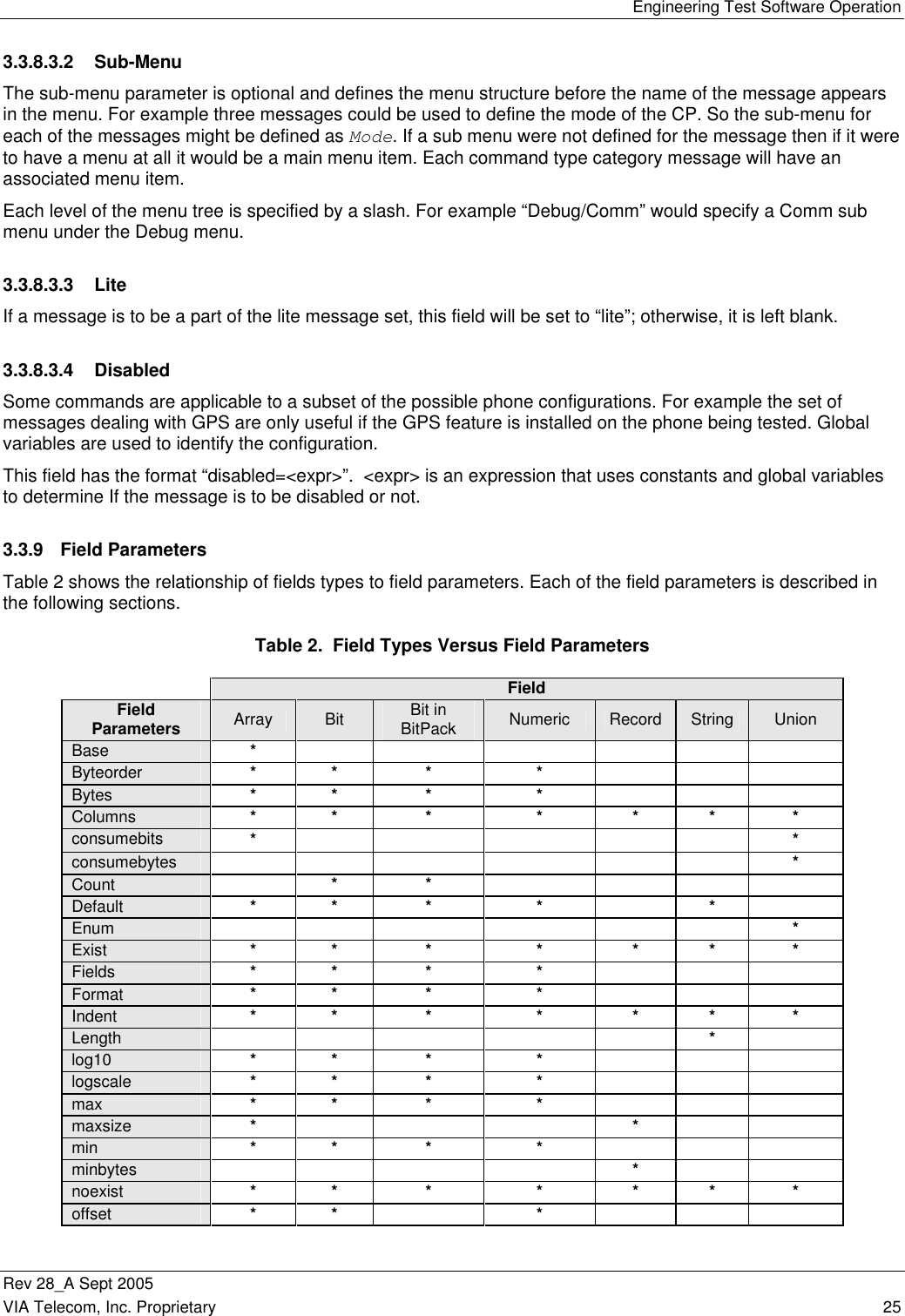
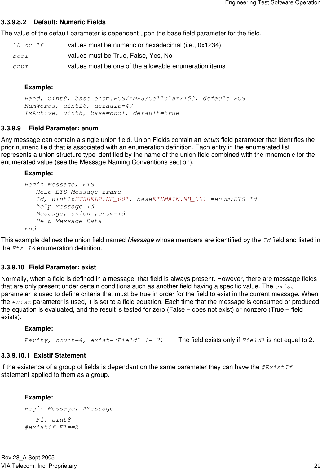
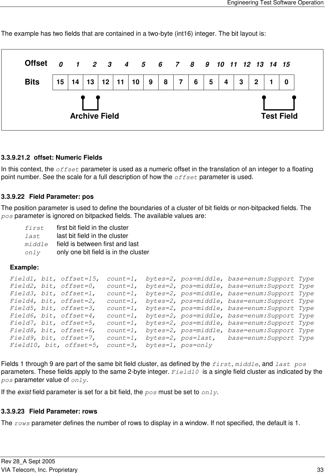
![Engineering Test Software Operation Rev 28_A Sept 2005 36 VIA Telecom, Inc. Proprietary 3.3.9.28 Field Parameter: Hidden The hidden field parameter is used to hide the values of a field from the user. The format of this parameter is “hidden=<expr>”. When the expression is nonzero the field will be hidden. 3.3.9.29 Field Parameter: ReadOnly The readonly field parameter is used prevent the user from modifying a field. The format of this parameter is “readonly=<expr>”. When the expression is nonzero the field can only be viewed by the user and cannot be modified. Note: This option is only relevant to command messages. Fields within response messages are implicitly readonly. 3.3.10 Expression Expression has the following rules: 1. Expression operators + Addition - Subtraction * Multiplication / Division % Modulation ! Not & Bit And | Bit Or ^ Bit Xor && Logical And || Logical Or == Equal To != Not Equal To > Greater Than < Less Than >= Greater Than or Equal To <= Less Than or Equal To ? Question Mark : Selection 2. Special Functions Count_of({path[]} expression) Refer to paragraph 3.3.10.2 COUNT_OF. 3. A selector expression is supported. It takes the form of: expression ? TrueResult : FalseResult 4. If an expression does not match any of the special functions and is not numeric, it is assumed to be a field name. 5. Operator precedence is observed based on conventional C language.](https://usermanual.wiki/VIA-Telecom/ORCA-PCIE/User-Guide-1265142-Page-50.png)
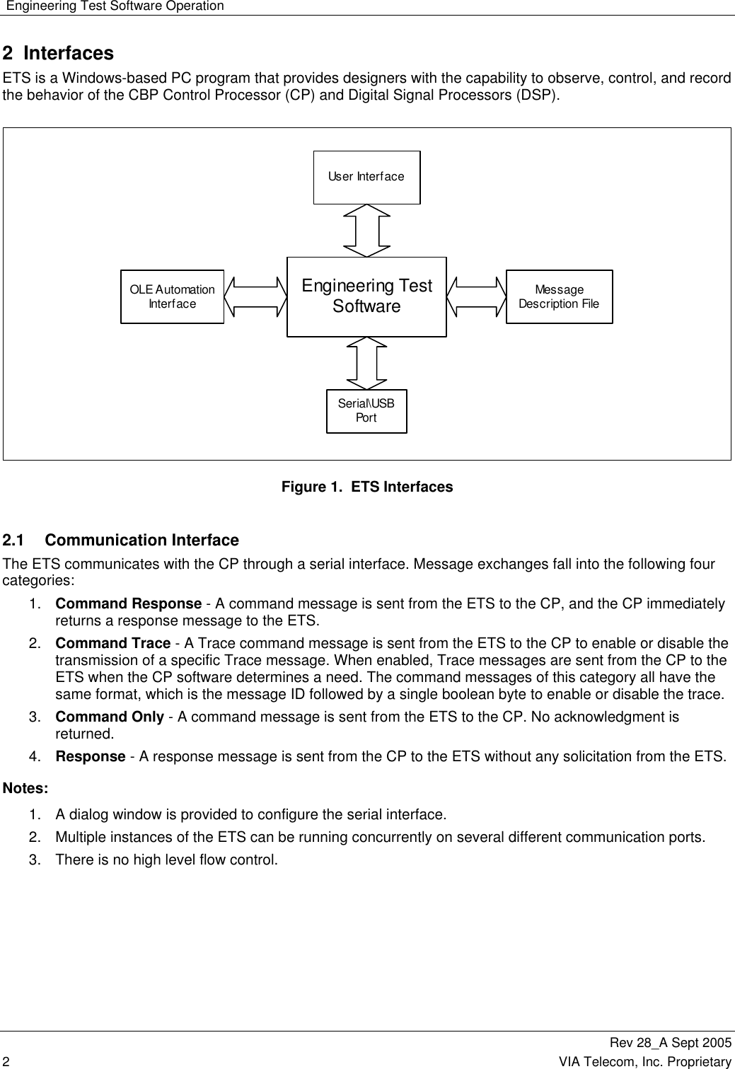
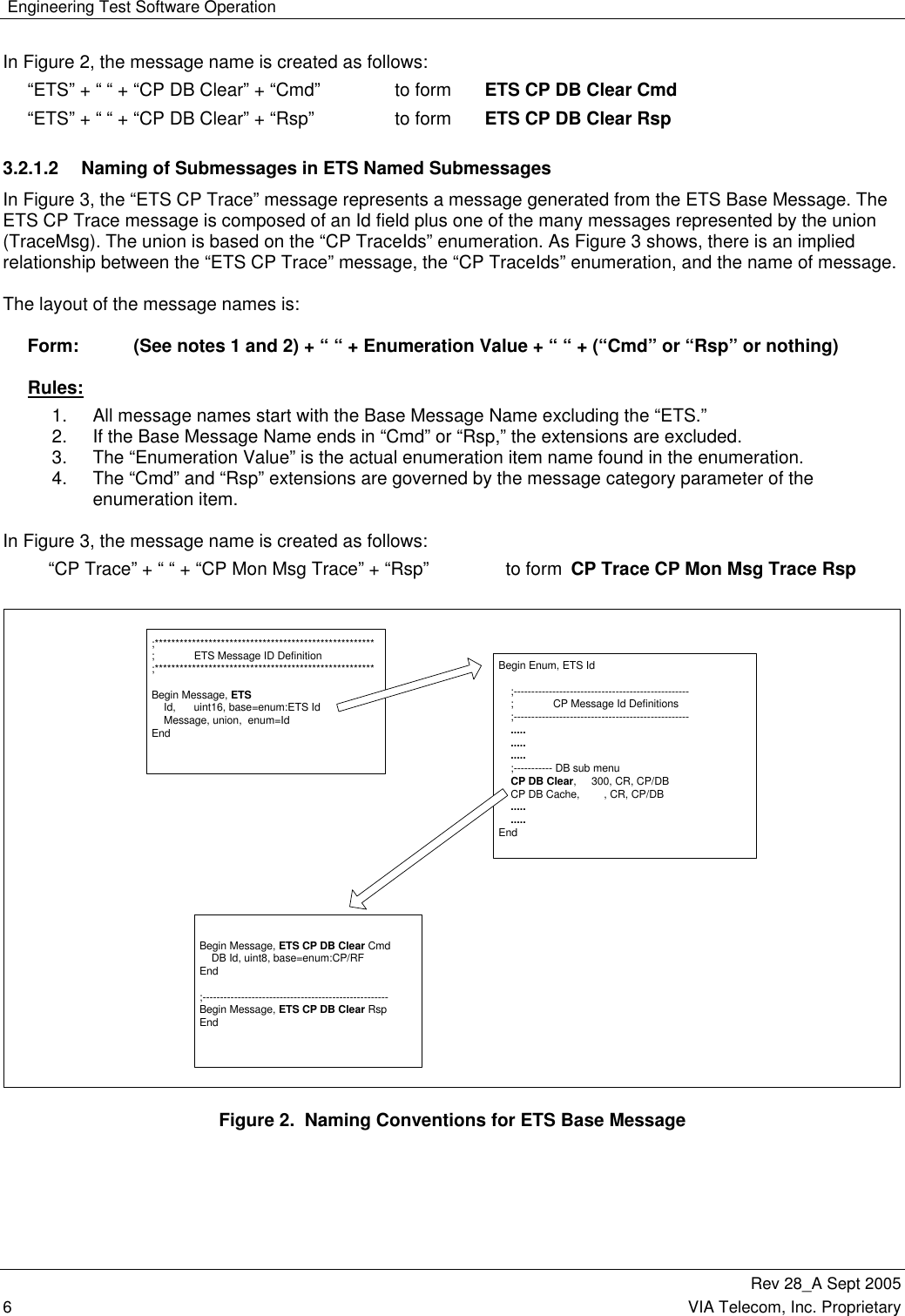
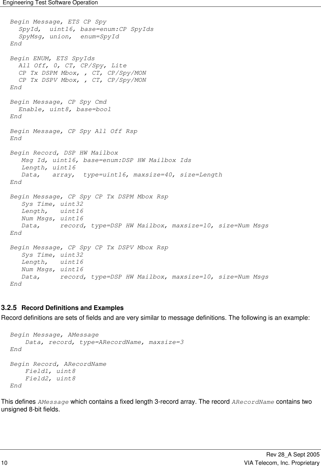
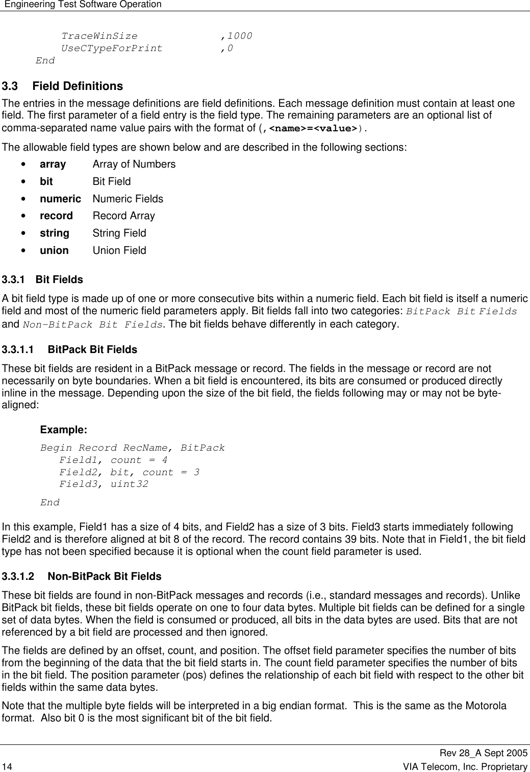
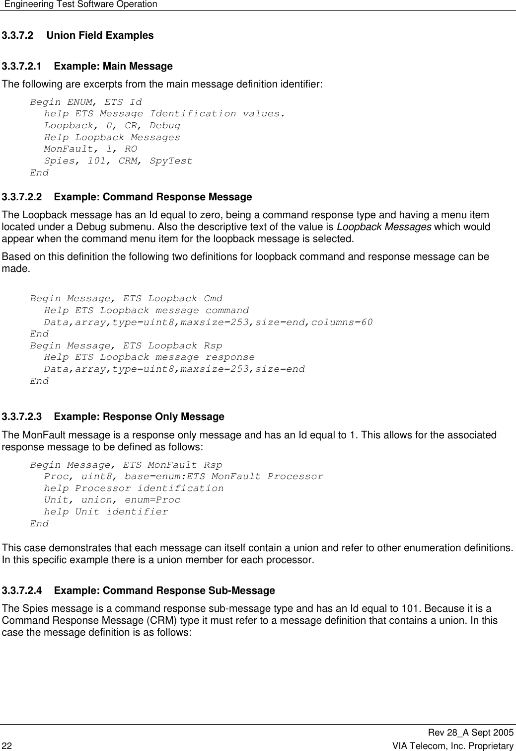
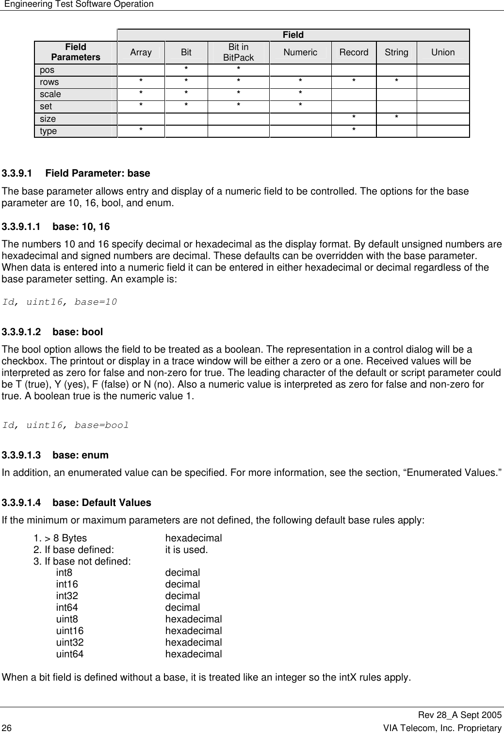
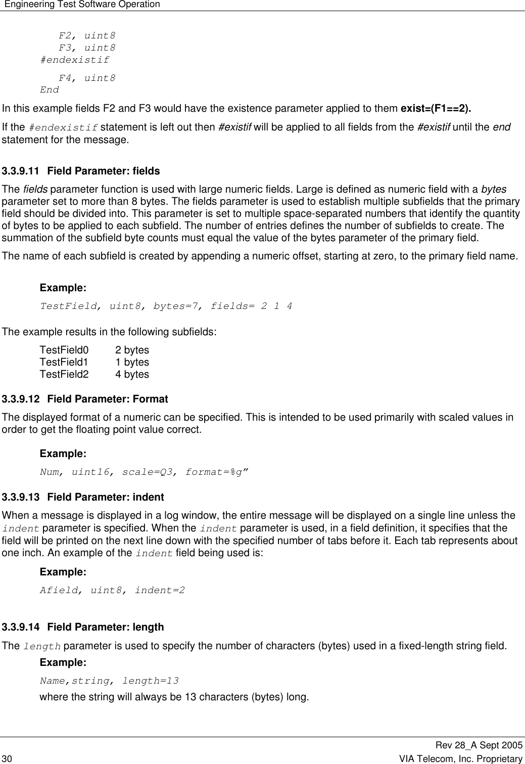
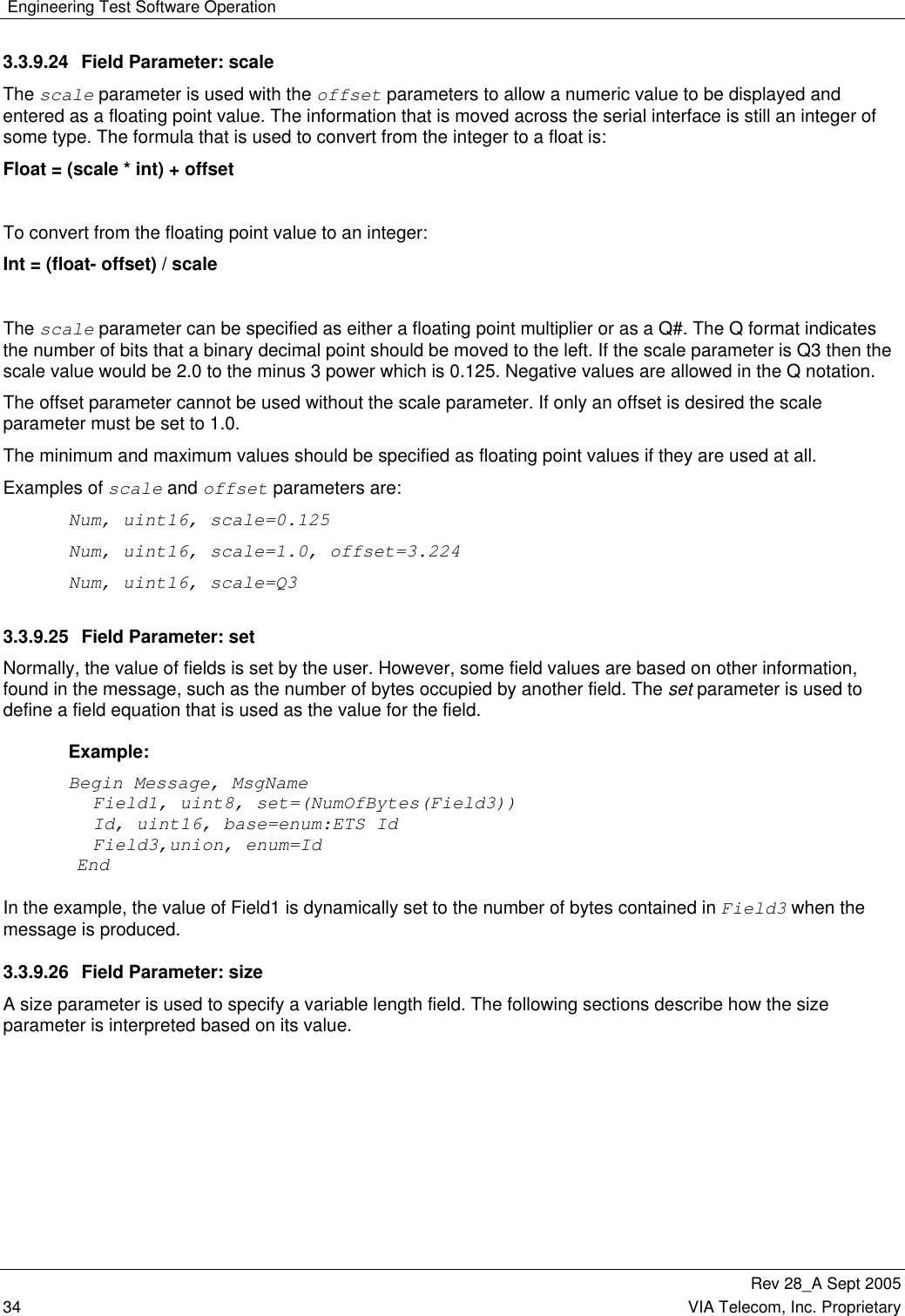
![Engineering Test Software Operation Rev 28_A Sept 2005 VIA Telecom, Inc. Proprietary 37 3.3.10.1 Field Names as Entities Field names are used as entities in expressions. When a message consumption or production is in progress, the field, associated with the name, is queried for its value or size. In most cases, the queried field is present in the same message as the field that contains the field (see the Length and Data fields in the example). There are some message definitions that have dependencies to fields that are not in same message level or record. In the example, the existence of the TimeValue field, of the Test Record, is dependent upon the DataSize field in the message level that contains the record. To create a path to the DataSize field, DOS style notation of “..\” is used. The notation can be used to continue up as many levels as necessary (i.e., ..\..\.. and so on). Example: Begin Message, ETS CP FSI Block Read Rsp DataSize, uint16, base=10 Length, uint16, base=10 Pad, record, type=Test Record, maxsize=1 Data, array, type=uint8, maxsize=512, size=Length, base=16, indent=1 End Begin Record Test Record TimeValue, uint16, exist= (..\DataSize > 3) End 3.3.10.2 COUNT_OF Count_of({path[]} expression) This was defined to handle an odd case in the IS2000 Rev. C specification. It requires that the number of occurrences of a field being set to 1 with in a set of records need to be counted in order to determine the size of another record array. This function returns a count of the number of times that the expression evaluates to non-zero for each case of the path being applied to the fields within the expression. The path must be a sequence of field specifiers that identify a record array. The expression will contain fields. In this context the field name is first checked to see if it exists in the current message, then if it is a global variable and last if it is a member of the record identified by the path. The following is an example. Afield, array,type=int8,maxsize=20,size=count_of({..\FirstRec[]\LowerRec[]} AfieldInLowerRec==1)](https://usermanual.wiki/VIA-Telecom/ORCA-PCIE/User-Guide-1265142-Page-51.png)
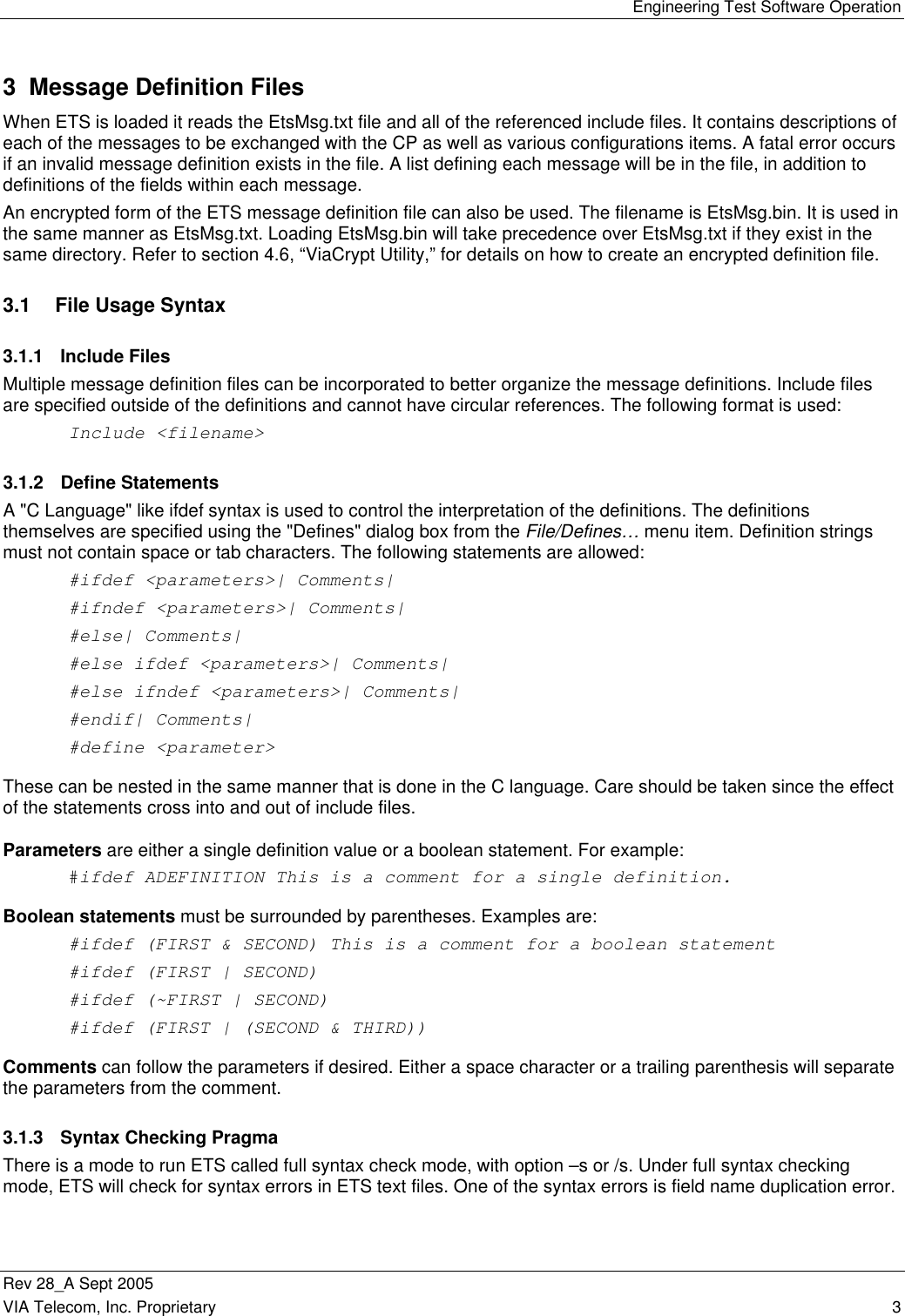
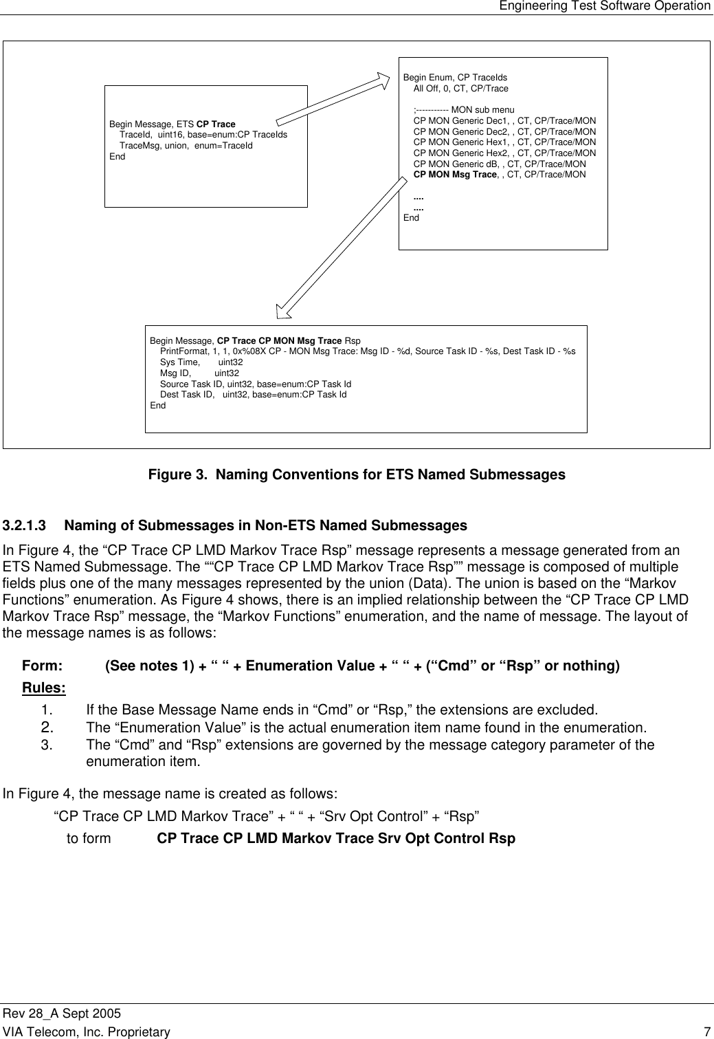
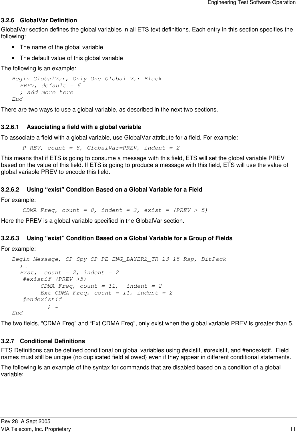
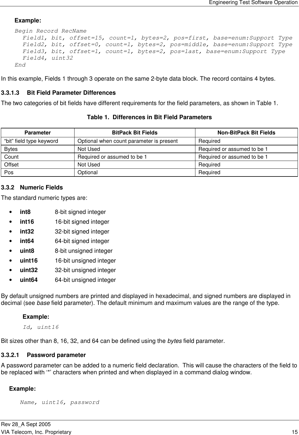
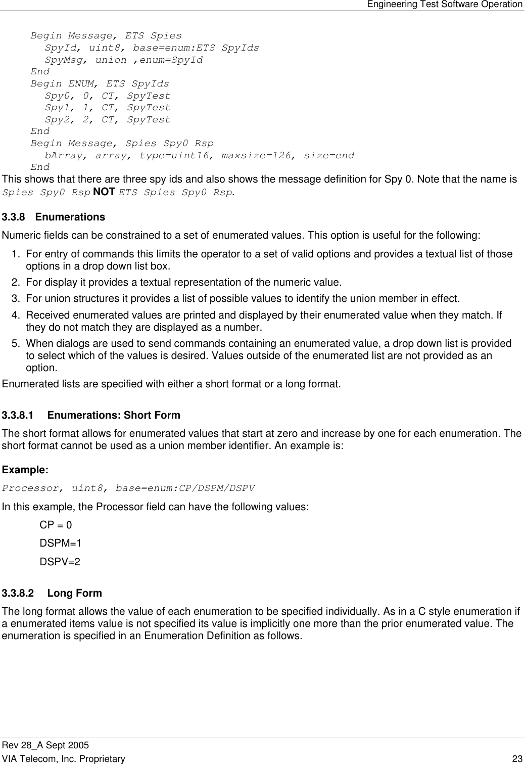
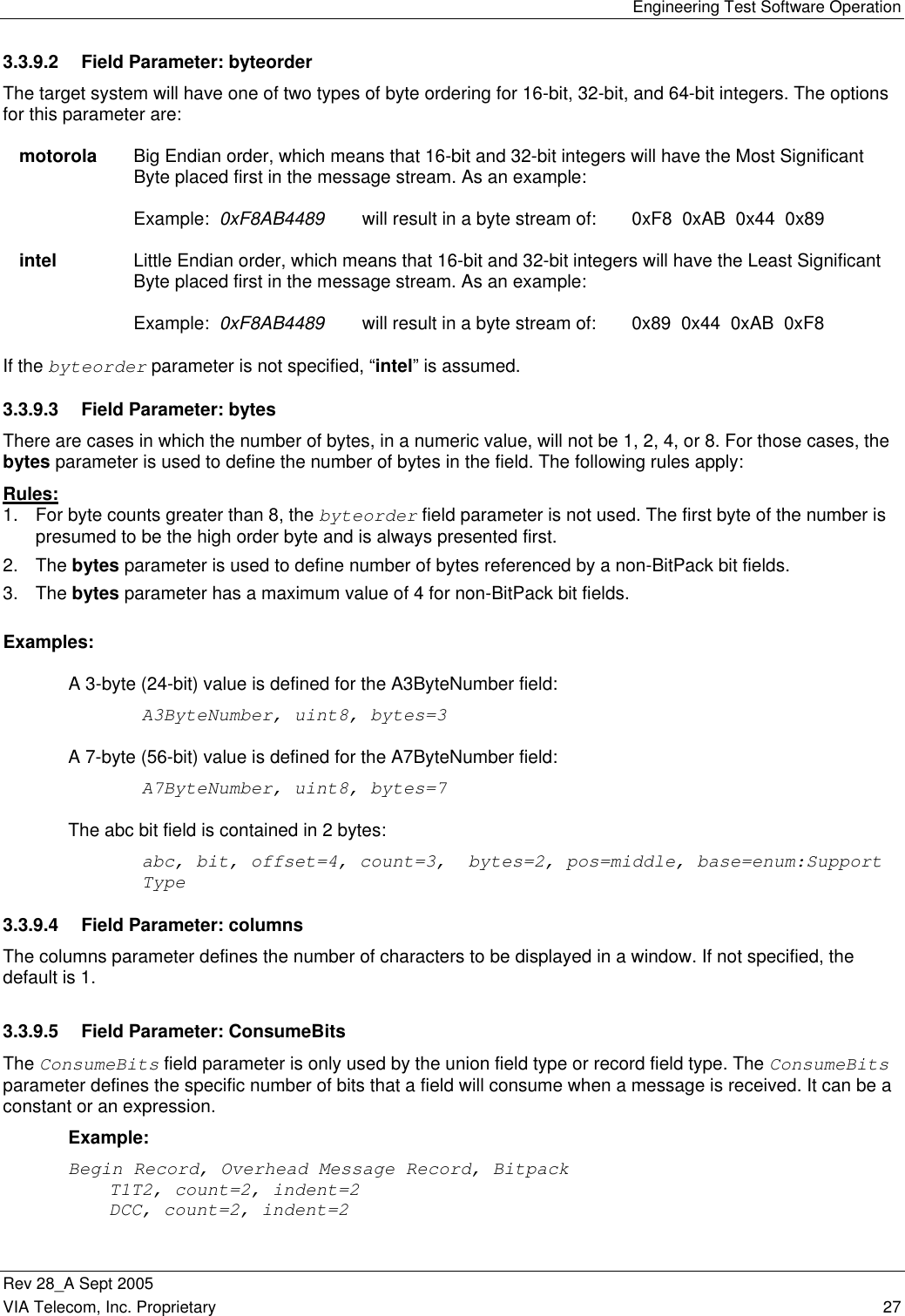
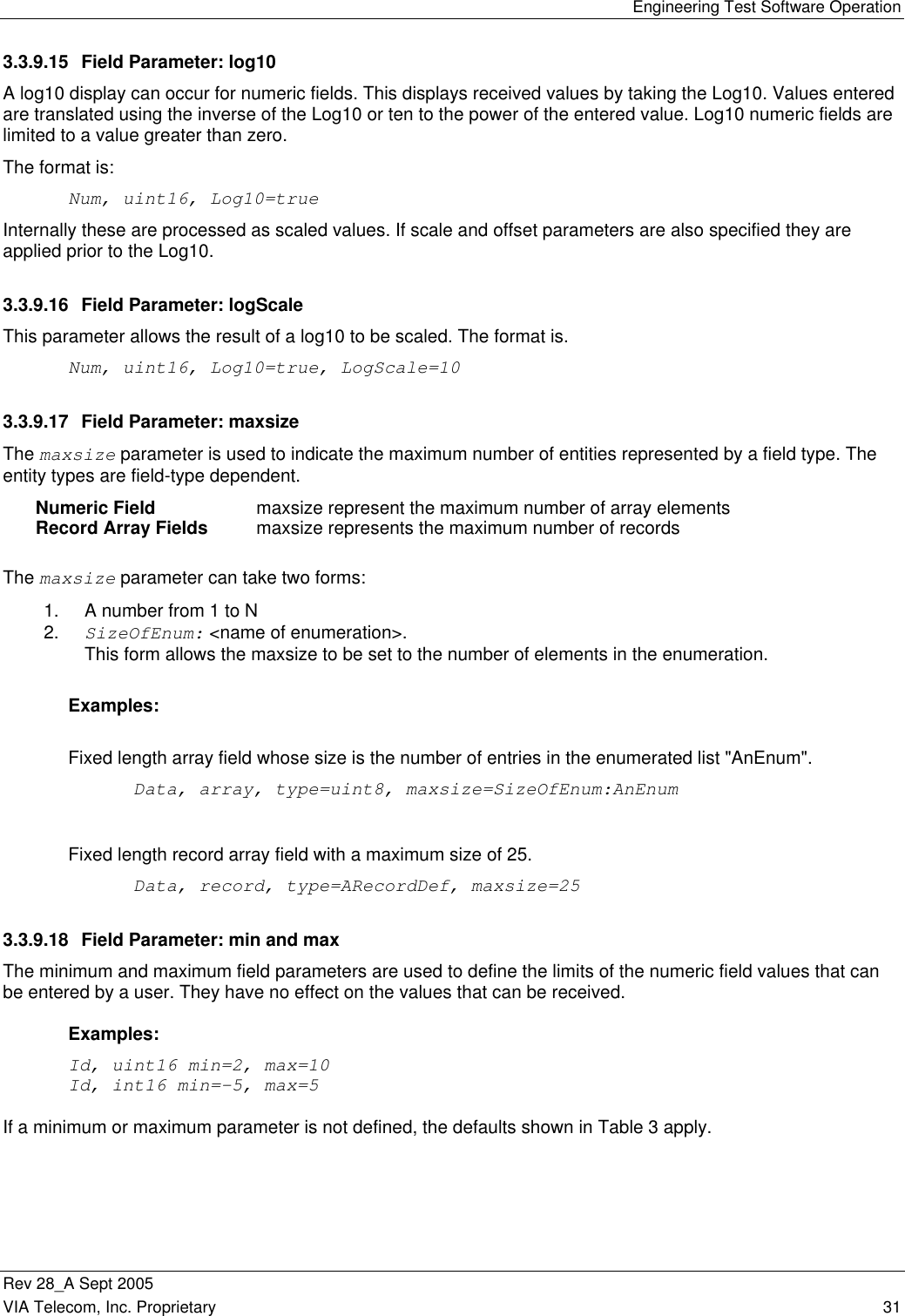
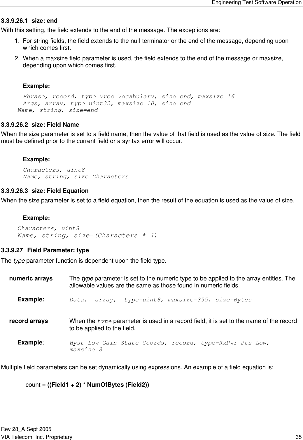
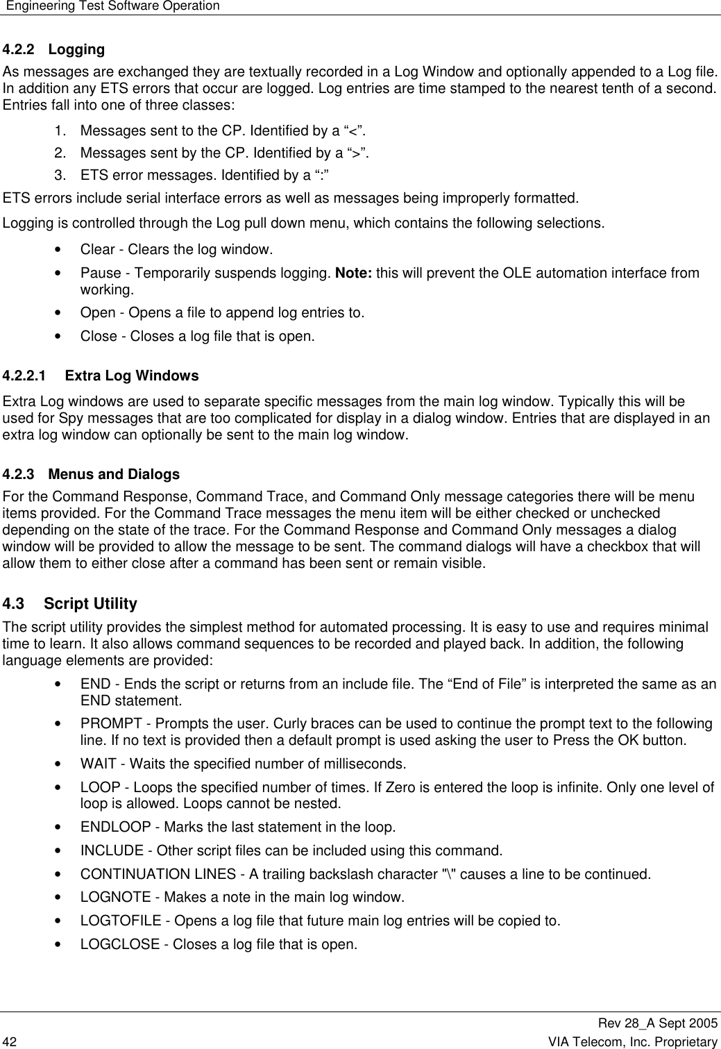
![Engineering Test Software Operation Rev 28_A Sept 2005 VIA Telecom, Inc. Proprietary 41 Table 4. Ets Options Dialog Selections Option Description Max messages per Second Limits the maximum number of messages that ETS will send to the CP in a second. When this is set to 0, there is no limit. This option is initialized to 0. Max messages in Log Window This sets the maximum number of messages that will be displayed in the main log window. This option is initialized to 1000 messages. Max messages in Trace Window Sets the maximum number of messages to be displayed in the Trace window. This option is initialized to 1000 messages. Transfer Window Size When performing uploads, downloads, and loopback tests, multiple data transfer messages can be sent before an acknowledgement is received. The number of messages is called the "Transfer Window Size.” This option is initialized to 4 and should not need to be changed. Initial Baud Rate This is the baud rate that ETS will use when started. The baud rate can be changed later by using the Serial Port Configuration Dialog from the Debug/Comm/Serial… menu item. This option is initialized to 115,200 Baud. Data Download Start Addr This is the default start address for the speech download buffer. This option is initialized to 0x2000000. Data Upload Start Addr This is the default start address for the speech upload buffer. This option is initialized to 0x2040000. Flash Download Timeout (Sec) The number of seconds that are allowed for the CP to acknowledge a flash download command. This option is initialized to 25000 ms (25 seconds). Popup Fault Log When checked, the fault log will be made the front window when an entry is made. This option is initially checked. Popup Comm Status on Error When checked, the Communications Status dialog pops up when an error occurs on the serial interface. This could be either a character error, such as parity or framing, or a message level error such as checksum for message framing. This option is initially unchecked. Maximum Menu Entries Sets the maximum number of menu entries that are allowed before the menu is replaced with a dialog box. This option is initialized to 40. Ignore Underflow Errors When checked, all underflow errors will be ignored. Underflow errors are generated when ETS receives less data than is defined for an entry in the definition text file. This option is initially checked. Log Notes to Trace Window When checked, notes that are entered from the COM interface are entered in both the main and the trace windows. This option is initially unchecked. Use C-Type Pathing for Printing When checked, all message printouts will use the C Language type pathing of xx.yy[3].rr. When not checked, no pathing will be applied to message fields except when records are present. When records are present, the pathing will be of the type fieldname.X where X is the record number. This option is initially checked. Serial Port DTR Enable When checked, enables the assertion of the DTR signal on the serial interface port. This option is initially unchecked. Send Break Char In Msg Preamble When checked, send a message preamble which contains a break character (0x00) followed by a multiple millisecond (see Preamble Delay option) pause followed by the start of message SYNC character. This preamble is sent before each message transmitted by ETS with the exception that if messages are clustered together, the preamble is only sent before the first message in the cluster. This preamble is used to wake up the CP from deep sleep. This option is initially checked. Preamble Delay in Msec This value is the delay used when the message preamble option is enabled. The option is initialized to 12 milliseconds. Log Message Received Errors Enables logging of errors in the received message framing. Auto Config Load When checked, the currently loaded Configuration file will be reloaded when a phone (MSUT) sends a “Configuration Info” message.](https://usermanual.wiki/VIA-Telecom/ORCA-PCIE/User-Guide-1265142-Page-55.png)
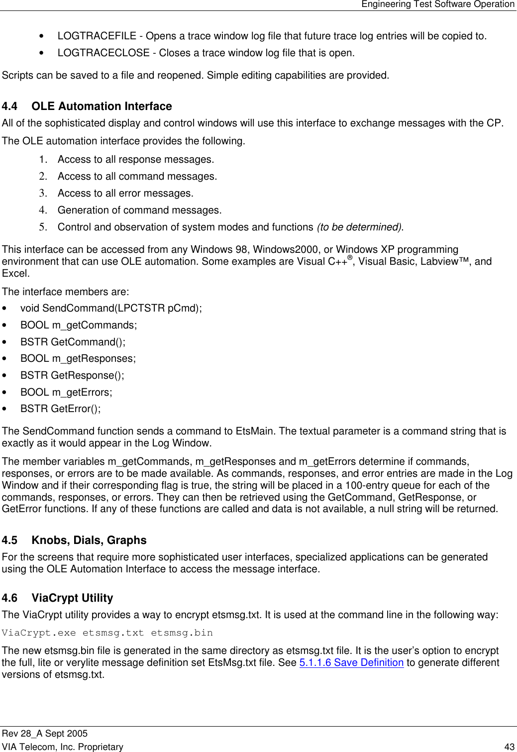
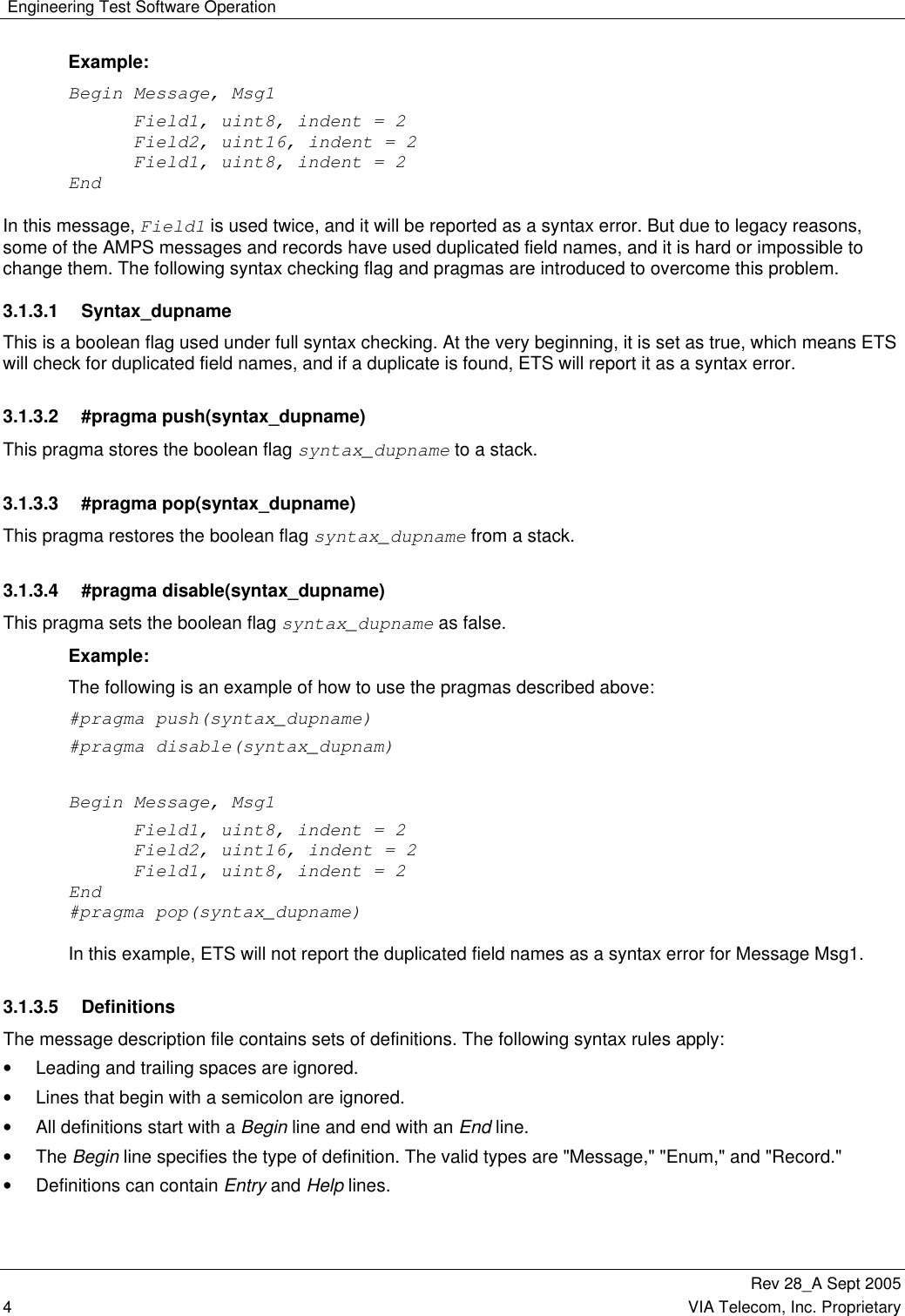
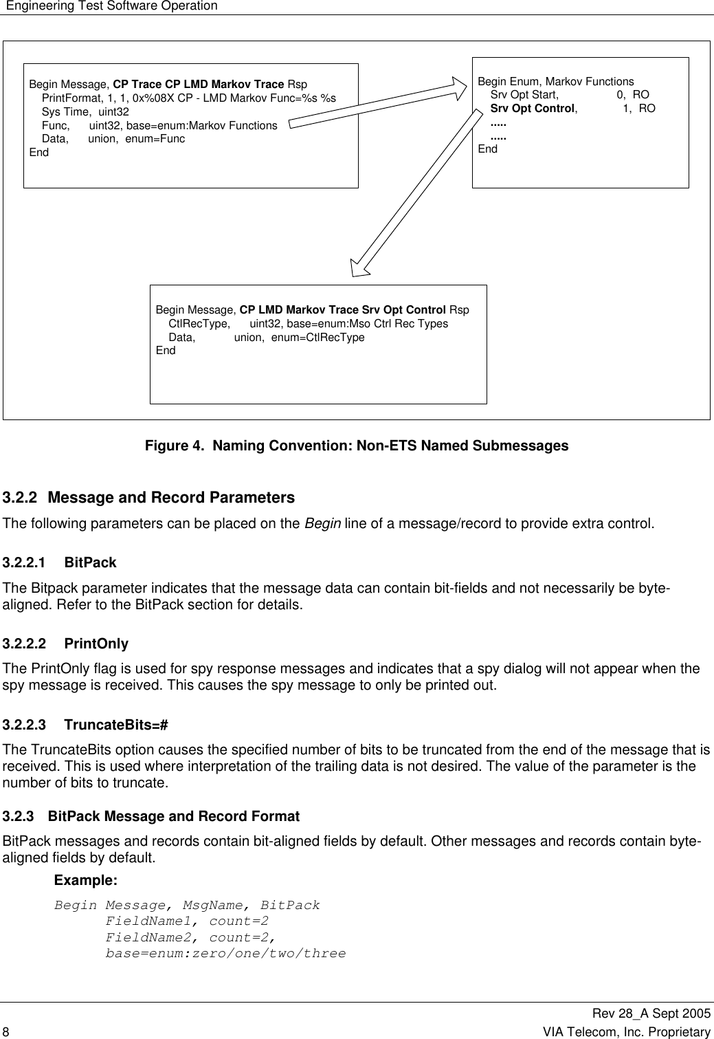
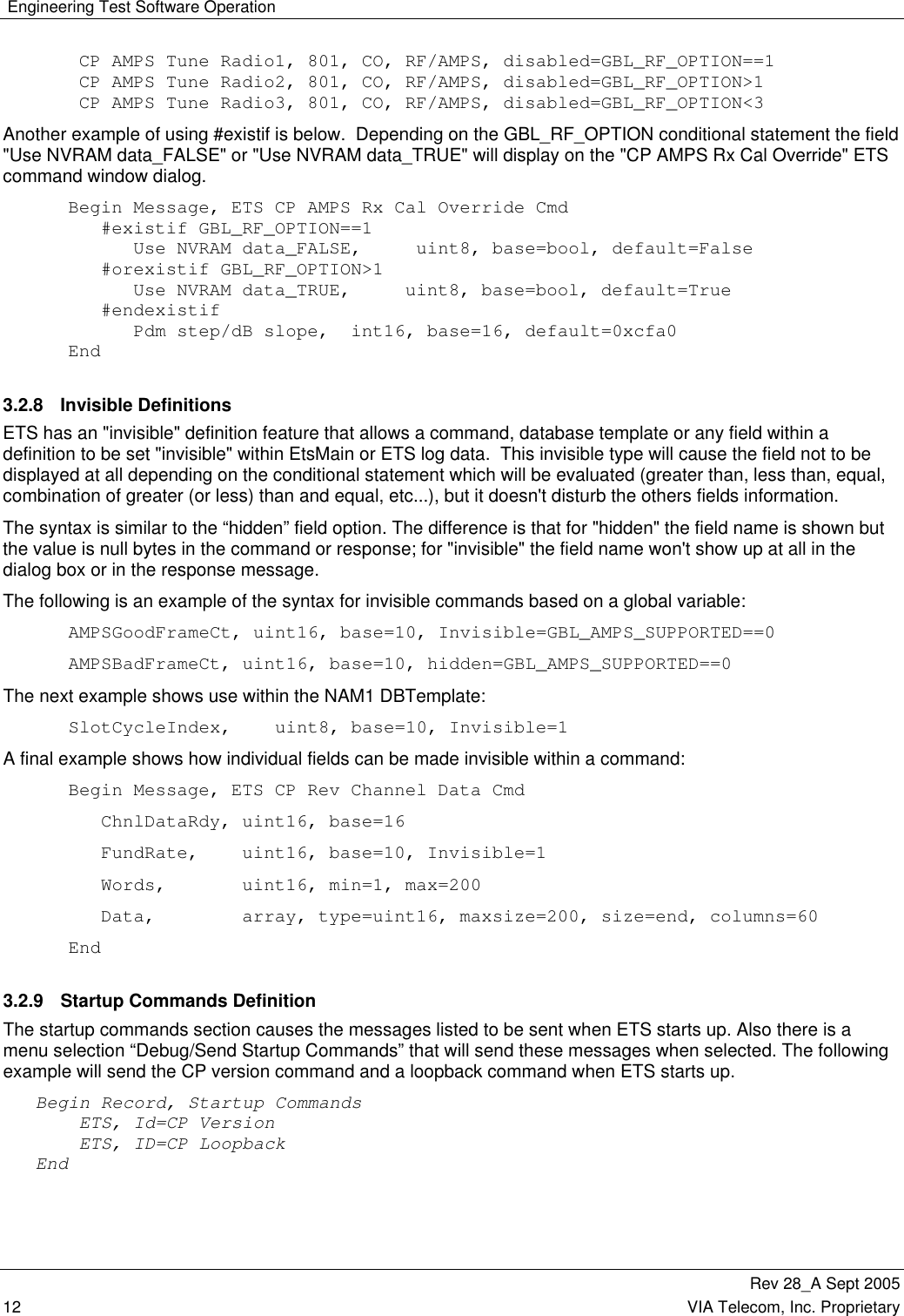
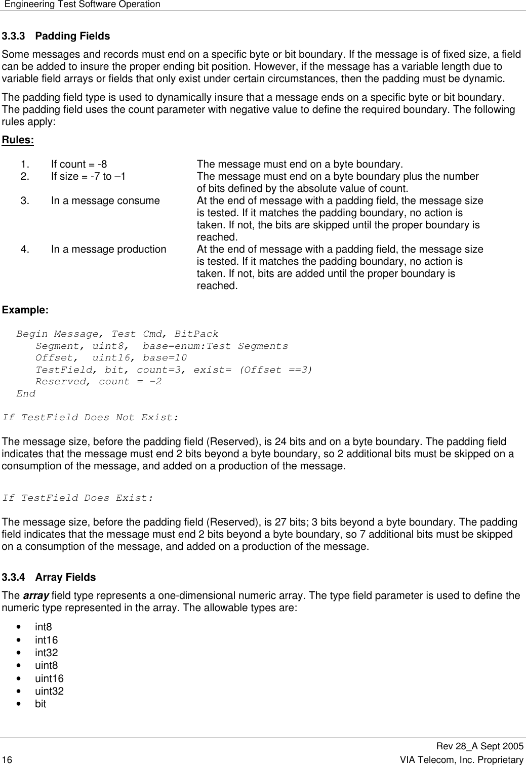
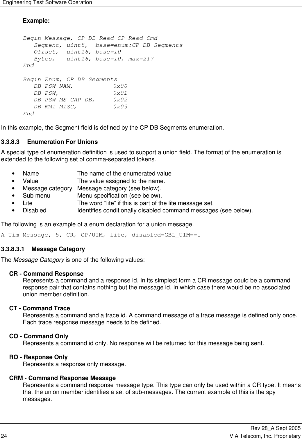
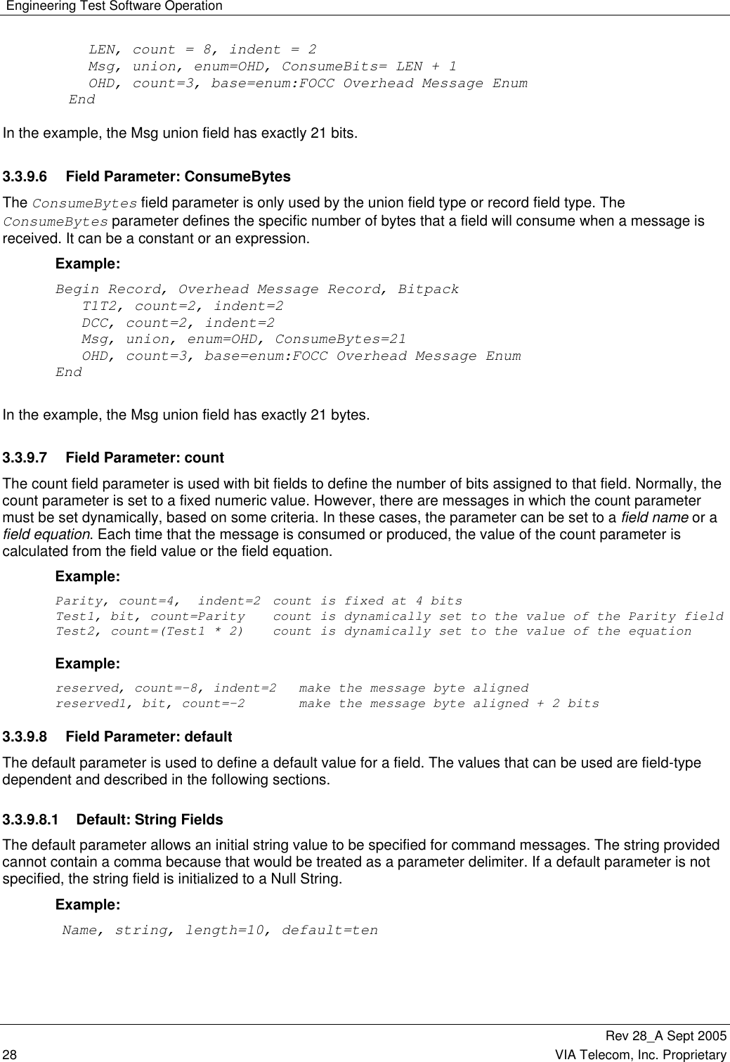
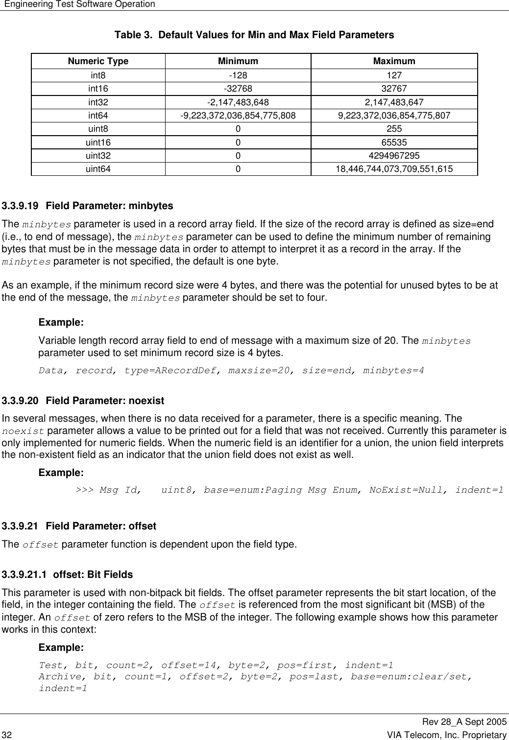
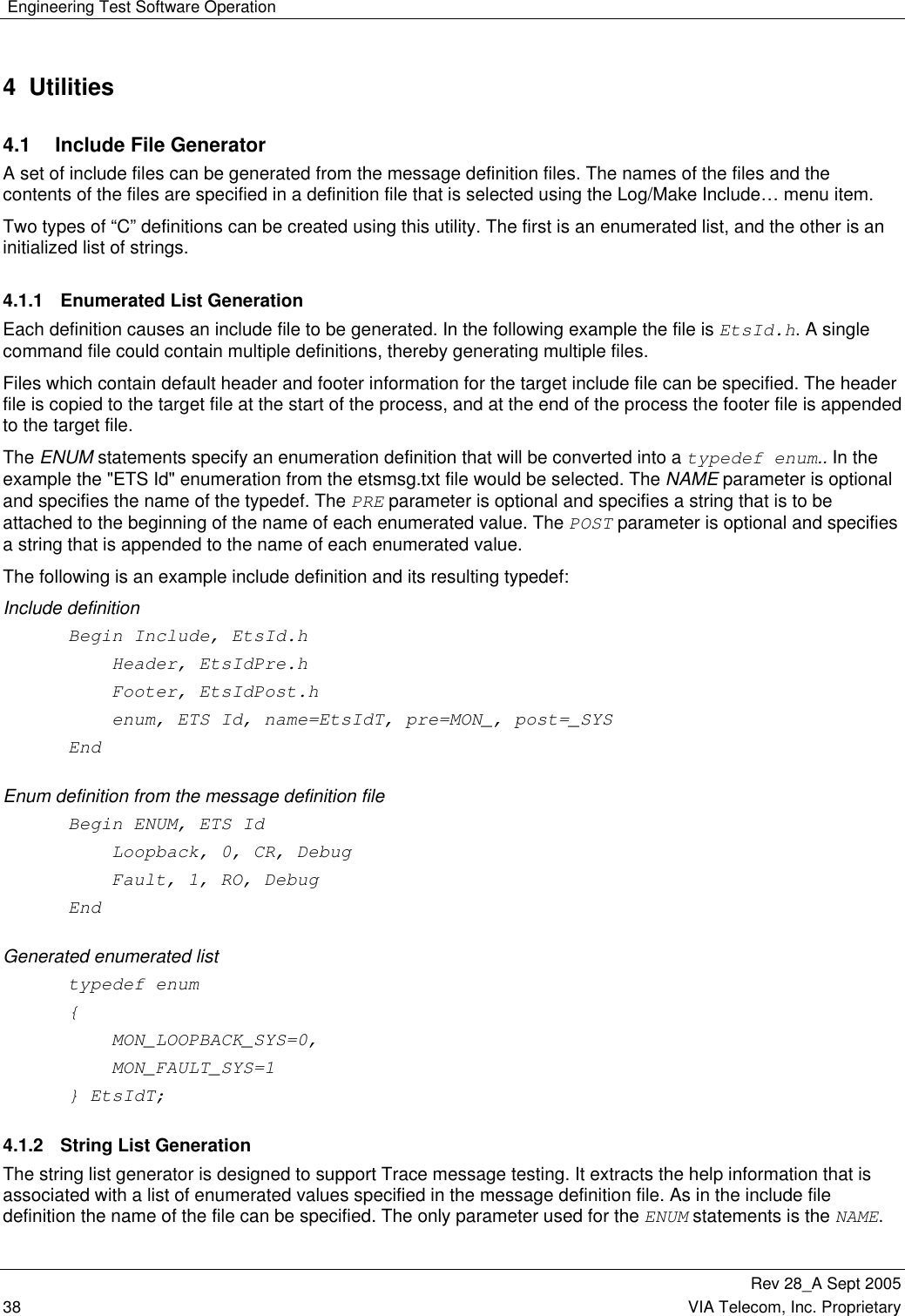
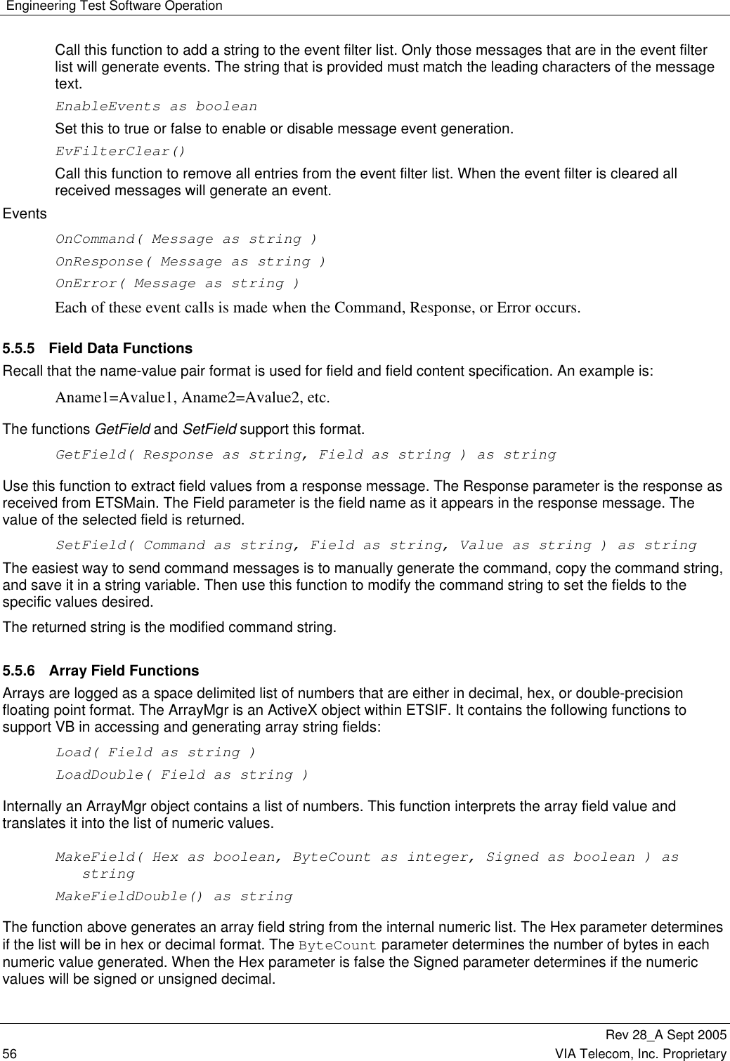
![Engineering Test Software Operation Rev 28_A Sept 2005 46 VIA Telecom, Inc. Proprietary TraceManagementCommunicationInterfaceMenu HandlerMessageDefinitionProcessingSystem ModeProcessingMessage RouterLog ProcessingOLE InterfaceMessage ObjectsCommuncationTest Figure 9. ETS Main Sub-Modules 5.1.1 Command Line Options ETSMAIN.EXE has several command line options to support various applications. The following is a list of those options. <filename> Specify an initial configuration file to be loaded. /S Do a full syntax check of the ETS message definitions. /Port=# Specify the communication port to connect to. /WinMode=[norm, min, hide] Specify the initial display mode of ETS, /D=<define> Add a define from the command line. /SaveDefs=<filename> Saves the definitions to a file and then terminates ETS. /LockConfig Causes the config file to be locked. ETSMAIN.EXE <pathname and config file name> /Port=<port specifier> /WinMode=<mode specifier> 5.1.1.1 Configuration File <filename> Configuration files contain ETS window position information as well as default parameters for command messages. ETS can be manually set up in a specific way and then have that setup saved in a configuration file. Later it can be reloaded to restore the previous setup. When a configuration file is loaded the required spy or trace commands are sent to the CP. Users should NEVER need to modify these configuration files manually. 5.1.1.2 Syntax Check /S This option causes ETS to perform a detailed syntax check of the message definitions. Normally ETS will do a limited amount of syntax checking when it loads in order to minimize the amount of time it takes to start ETS.](https://usermanual.wiki/VIA-Telecom/ORCA-PCIE/User-Guide-1265142-Page-60.png)
![Engineering Test Software Operation Rev 28_A Sept 2005 VIA Telecom, Inc. Proprietary 59 5.5.11.3 Function Enable(Enable As Boolean) As Boolean This function enables or disables the delivery of messages in the Queue. Disabling the queue and then enabling it will flush all entries from the queue. 5.5.11.4 Function GetAllResponses() As String Returns a new line separated list of all the responses currently in the queue. This causes all of the messages to be removed from the queue. Use this function when higher rates of messages are expected because the number of out of processes calls to ETS will be minimized. 5.5.11.5 Function GetOverRunCount() As Long Returns the number of messages that could not be put in the queue because space was not available. The overrun count will be set to zero after this function is called. 5.5.11.6 Function GetResponse() As String Returns the next message in the queue. The returned message is removed from the queue. 5.5.11.7 Sub SetSize(Size As Long) Sets the maximum number of messages that the queue will contain. If this function is not called the maximum number of message allowed in the queue is 100. 5.6 VIAIF Dynamic Link Library The ViaIf.dll provides the functionality of the EtsIf.ocx without the user interface of ETS. In addition the interface is provided as an in process COM connection because it is a DLL. The main interface of the ViaIf.dll is identical to EtsIf.ocx. A test program ViaIfTest is provided in Visual Basic that demonstrates the compatibility between EtsIf.ocx and ViaIf.dll. Because the ViaIf.dll is not connected to ETS it requires a second interface to setup the communication with the phone as well as to select the message definitions to be used. 5.6.1 ViaSetup Interface The ViaSetup interface allows the application to select definition files and and communications ports as well as other functions as listed below. 5.6.1.1 LoadDefinitions LoadDefinitions([in] BSTR pPathName); Loads the definition file specified in the pPathName parameter. 5.6.1.2 OpenCommInterface OpenCommInterface([in] BSTR pInterfaceIdentifier, [in] BSTR pParameters); Opens the selected Communications Interface. pInterfaceIdentifier – “COM1, COM2,… or USB.](https://usermanual.wiki/VIA-Telecom/ORCA-PCIE/User-Guide-1265142-Page-73.png)
![Engineering Test Software Operation Rev 28_A Sept 2005 60 VIA Telecom, Inc. Proprietary pParameters – Used only when COM# is selected. The string must contain the following: Port identifier, Baud Rate, 0 or 1 to enable or disable the TxPreamble Preamble delay in milliseconds. Example: “COM1, 115200, 1, 20” Open COM1 at 115200 baud, enable the TxPreamble with 20 milliseconds. 5.6.1.3 UnloadDefinitions UnloadDefinitions(); Unloads the definitions that were loaded with the LoadDefinitions call. 5.6.1.4 CloseCommInterface CloseCommInterface(); Closes the communications interface. 5.6.1.5 GetCommStatus GetCommStatus([out, retval] BSTR * pStatus); Returns the communications status. For serial ports this is in the form “COM1 115200 N,8,1”. For the USB port this is in the form "USB - NOT Connected" or “USB - Connected”. 5.6.1.6 GetCommStatistics GetCommStatistics([out, retval] BSTR * pStats); This provides the statistics since either a connection was established or since the last call the ResetCommStatistics. It provides the following information in a string. “STATS, SampleTime=0, MsgsRcv=0, MsgsXmt=0, MsgRcvErrors=0, MsgXmtErrors=0, BytesRcv=0, BytesXmt=0, DrvRxErrors=0, DrvTxErrors=0, DrvRxHighWater=0, DrvTxHighWater=0, SerFramingErrors=0, SerOverrunErrors=0, SerParityErrors=0” 5.6.1.7 ResetCommStatistics ResetCommStatistics(); Resets the statistics provided in the GetCommStatistics call. 5.6.1.8 GetAutoRspQ GetAutoRspQ([out, retval] IAutoRspQ ** ppAutoRspQ); Returns a reference to AutoRspQ object. This is identical to the AutoRspQ provided in the EtsIf.ocx interface. 5.6.1.9 RawHex RawHex([in] BOOL TxHex, [in] BOOL RxHex); Enables or disables logging of Raw Hex information when logging is active.](https://usermanual.wiki/VIA-Telecom/ORCA-PCIE/User-Guide-1265142-Page-74.png)
![Engineering Test Software Operation Rev 28_A Sept 2005 VIA Telecom, Inc. Proprietary 61 5.6.1.10 ResetPolarity ResetPolarity([in] BOOL Positive); Sets the ResetPolarity. If this call is not made the reset polarity will be negative which is compatible with the CDS4 boards. 5.6.1.11 ResetBoard ResetBoard(); Performs a board reset using the CTS serial interface line. This will only have an effect if the active interface is a serial port. The CTS line is used in the CDS boards to allow an application to cause a hard reset of the board. 5.6.1.12 SendDeferredCommand SendDeferredCommand([in] long Milliseconds, [in] BSTR pCommand); This works the same as the SendCommand call in the main interface except that the command will not be sent until the number of milliseconds specified has elapsed. 5.6.2 ViaBinary Interface The ViaBinary interface allows applications to bypass the translation of messages between textual and binary formats. Its purpose is to reduce the processor loading caused by the message translation process. This has proven very useful when downloading large quantities of data. The design provides a filter mechanism to identify which received messages are to be put into a RxQueue. The RxQueue is read using the GetMessage function. 5.6.2.1 SendMessage SendMessage([in] VARIANT * pSafeByteArray); Sends a binary message to the CP. 5.6.2.2 GetMessage GetMessage([in] long Milliseconds, [out, retval] VARIANT * pSafeByteArray); Retrieves a message from the CP. The mount of time to wait is specified in Milliseconds. If this parameter is set to zero the function will return immediately if a message is not in the queue. When a message is returned by this function it is also deleted from the RxQueue. 5.6.2.3 Clear Filter ClearFilter(); Clears the received message filter 5.6.2.4 AddToFilter AddToFilter([in] VARIANT * pSafeByteArray); Adds a message header to the Filter. Any received message that matches this binary header will be available through the GetMessage function.](https://usermanual.wiki/VIA-Telecom/ORCA-PCIE/User-Guide-1265142-Page-75.png)
![Engineering Test Software Operation Rev 28_A Sept 2005 64 VIA Telecom, Inc. Proprietary Rsp: "BINLOG, Cmd=Playback, Status={Ok|Fail}, Cause=<cause>" 5.8.1.4.1 Command Parameters Path=<pathname> The pathname of the file to be playback. 5.8.1.4.2 Response Parameters Status={Ok|Fail} If it is Ok then the binary file has been playback. If it is Fail then the file can not be playback for some reason Cause=<cause> Specify the failure reason if Status = {Fail} 5.8.2 GETDEF Add support to access Message Definition for EtsMain.exe and ViaIf.dll. Both Command and Response string start with “GETDEF”. The following are the examples for GETDEF commands and responses. The messages are described as the command (Cmd) to be sent to ETS or ViaIf.dll and the response (Rsp) that is returned. 5.8.2.1 Get Definition Entry Count This message pair is used to get Definition Entry count Cmd: "GETDEF, {Record|Message|Enum|…} = <definition name> Rsp: "GETDEF, Entries=<number of entries>, <parameters>" 5.8.2.1.1 Command Parameters {Record|Message|Enum|...} = <definition name> The name of the Definition[l1]. 5.8.2.1.2 Response Parameters Entries=<number of entries> The number of entry in this Definition file <parameters> Returned parameters if there’re any 5.8.2.1.3 Example Example of a Record Definition[l2]: Begin Record, ETS Definition Version Project ,CBP4.05 Ets Version ,5.4.0 End In this example, Cmd: "GETDEF, Record = ETS Definition Version" Rsp: "GETDEF, Entries = 2” 5.8.2.2 Get Definition Entry Value by Entry Number This message pair is used to get Definition Entry Value by Entry number Cmd: "GETDEF, {Record|Message|Enum|...} = <definition name>, Entry = <entry number> Rsp: "GETDEF, <entry>"](https://usermanual.wiki/VIA-Telecom/ORCA-PCIE/User-Guide-1265142-Page-78.png)
![Engineering Test Software Operation Rev 28_A Sept 2005 VIA Telecom, Inc. Proprietary 69 HRESULT Status([in] BOOL Active, [in] long TotalBytes, [in] long TransferredBytes, [in] BSTR State); Active: This is True when a Transfer is in progress or if the downloader is otherwise in the process of doing something. TotalBytes: The total number of bytes that will be transferred. TransferredBytes: The number of bytes that have been transferred. State: The State of the Transfer.](https://usermanual.wiki/VIA-Telecom/ORCA-PCIE/User-Guide-1265142-Page-83.png)
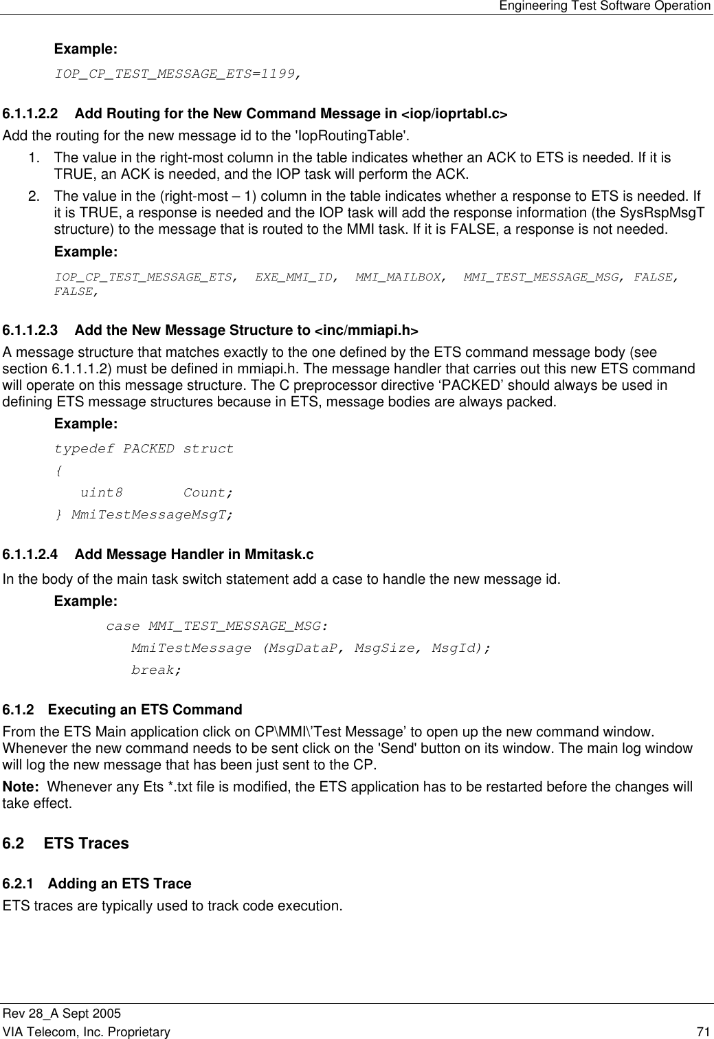
![Engineering Test Software Operation Rev 28_A Sept 2005 70 VIA Telecom, Inc. Proprietary 6 Adding Commands, Traces, Spies, Faults The purpose of this section is to provide instructions on how to add new ETS commands, traces, spies, and fault messages to ETS text files and CP software. All examples herein pertain to the MMI sub-unit. These instructions, however, can also be used to add new ETS commands, traces, spies and fault messages for other sub-units by replacing MMI with the other unit’s name wherever appropriate. The approach taken is to examine specific commands, traces, spies, faults have been integrated into ETS text files and CBP CP (.c, .h) files. Note that all numeric I.D.s occurring within square brackets, such as [1109] in section 6.1.1.1.1 can change between versions of software. However, these numeric I.D.s must always be consistent between the ETS text files and the CBP CP (.c, .h) files. 6.1 ETS Commands ETS commands are used to pass data to the CBP software. 6.1.1 Adding an ETS Command 6.1.1.1 Modify ETS Message Id and Message Body Definition Text Files On the ETS side, the file that defines all ETS commands is 'msg_id.txt'. The command message body definitions are defined in each sub-unit ‘<unit>_msg.txt’ file and are included by ‘etsmsg.txt’. We will now describe the steps for modifying both of these ETS text files. 6.1.1.1.1 Declare the New Command in ‘msg_id.txt’ Open the file ‘/msg_id.txt’. This file contains several sub-unit menu declarations, including MON, HWD, etc. Scroll down to the 'MMI Sub Menu' section in ‘msg_id.txt’ and add a new declaration for the new command. Example: CP Test Message, [1199], CO, CP/MMI The hard-coded value in square bracket [1199] is the value of the command ID and is optional. The logic works like a C language enumeration. If a value is not present, the command ID will be that of the previous command plus one. 6.1.1.1.2 Add the Command Message Body to ‘<unit>_msg.txt’ Open the file ‘/cp/mmi/mmi_msg.txt’. Go to the 'Start MMI Definitions' and add the command message body. Example: Begin Message, ETS CP Test Message Cmd Count, uint8, base=10 End 6.1.1.2 Modify CBP CP Software Files In the CBP CP software, adding an ETS command involves declaring the new ETS command ID in a global header file, routing the new command ID to the CP task which is expected to process the message, prototyping the new message structure in that task’s api file, and adding a message handler in its main message switch. These steps are described below. 6.1.1.2.1 Declare New Command ID in <inc/iopets.h> Add the new command id to the 'IopEtsMsgIdT' enumeration. Note that the same number, [1199] is used here as in the ETS 'msg_id.txt' file.](https://usermanual.wiki/VIA-Telecom/ORCA-PCIE/User-Guide-1265142-Page-84.png)
![Engineering Test Software Operation Rev 28_A Sept 2005 72 VIA Telecom, Inc. Proprietary 6.2.1.1 Modify ETS Message Id and Message Body Definition Text files On the ETS side, the file that defines all ETS commands is 'trace_id.txt'. The command message body definitions are defined in each sub-unit ‘<unit>_trace.txt’ file and are included by ‘etsmsg.txt’. We will now describe the steps for modifying both of these ETS text files. 6.2.1.1.1 Declare the New Trace in trace_id.txt Open the file ‘/trace_id.txt’. This file contains several sub-unit menu declarations, including MON, HWD, etc. Scroll down to the 'MMI Sub Menu' section in ‘trace_id.txt’ and add a new declaration for the new trace. Example: CP MMI Test Msg, [0x263], CT, CP/Trace/MMI Again, the trace message id in the square brackets is optional. 6.2.1.1.2 Add the Trace Message Body to <mmi/mmi_trace.txt> Open the file ‘/cp/mmi/mmi_trace.txt’. Go to the 'Start MMI Definitions' and add the trace message body. Note that the MON task in the CP software that handles traces automatically adds a 32-bit system time variable to the top of the trace data structure. Therefore, the trace message body will have to include the variable “Sys Time, uint32” as its first argument. Example: Begin Message, CP Trace CP MMI Test Msg Rsp PrintFormat, 1, 1, 0x%08X CP - MMI VRec Msg: MsgId=%s, NewState=%s Sys Time, uint32 MsgId, uint32 End 6.2.1.2 Modify CBP CP Software Files In the CBP CP software, adding an ETS trace involves declaring the new ETS trace ID in a global header file and adding calls to MonTrace() to pass the desired information to ETS. 6.2.1.2.1 Declare New Trace ID in <inc/monids.h> Add the new trace id to the 'MonTraceIdT' enumeration. Example: MON_CP_MMI_TEST_MSG_TRACE_ID, 6.2.1.2.2 Add MonTrace() Calls to Source Code In the C source files, a 'MonTrace()' call can be added to send trace information to ETS wherever such information is desired. The prototype for 'MonTrace' is defined as follows: extern void MonTrace(uint16 TraceId, uint32 NumArgs, ...); Example: /* display the incoming message id and the Test Message */ MonTrace (MON_CP_MMI_TEST_MSG_TRACE_ID, 2, (uint32) MsgId);](https://usermanual.wiki/VIA-Telecom/ORCA-PCIE/User-Guide-1265142-Page-86.png)
![Engineering Test Software Operation Rev 28_A Sept 2005 VIA Telecom, Inc. Proprietary 73 6.2.2 Enabling an ETS Trace From the ETS Main application click on CP\TRACE\MMI\'trace name' to turn on or off a trace where 'trace name' is the name of the trace. In the above example, 'trace name' is 'CP MMI Test Msg'. The traces received from the CP will be displayed in the Trace window, only if the Trace is enabled through ETS; ETS passes a message to the CP MON task, when a trace is enabled by the user. By default all traces are turned OFF. Note: Whenever any ETS *.txt file is modified, the ETS application has to be restarted before the changes will take effect. 6.3 ETS Spies 6.3.1 Adding an ETS Spy ETS spies are typically used to display changes to data. 6.3.1.1 Modify ETS Message Id and Message Body Definition Text Files On the ETS side, the file that defines all ETS commands is 'spy_id.txt'. The command message body definitions are defined in each sub-unit ‘<unit>_spy.txt’ file and are included by ‘etsmsg.txt’. We will now describe the steps for modifying both of these ETS text files. 6.3.1.1.1 Declare the New Spy in ‘spy_id.txt’ Open the file ‘/spy_id.txt’. This file contains several sub-unit menu declarations, including MON, HWD, etc. Scroll down to the 'MMI Sub Menu' section in ‘spy_id.txt’ and add a new declaration for the new spy. Example: CP Mmi Test Spy, [0x1C1], CT, CP/Spy/MMI Again, the spy id in the square brackets is optional. 6.3.1.1.2 Add the Spy Message Body to <mmi/mmi_spy.txt> Open the file ‘/cp/mmi/mmi_spy.txt’. Go to the 'Start MMI Definitions' and add the spy message body. Note that the MON task in the CP software that handles spies automatically adds a 32-bit system time variable to the top of the spy data structure. Therefore, the spy message body will have to include the variable “Sys Time, uint32” as its first argument. Example: Begin Message, CP Spy CP Mmi Test Spy Rsp Sys Time, uint32 Test Data, array, type=int16, maxsize=64, size=end, columns=60 End 6.3.1.2 Modify CBP CP Software Files In the CBP CP software, adding an ETS spy involves declaring the new ETS spy ID in a global header file and adding calls to MonSpy() to pass the desired information to ETS. 6.3.1.2.1 Declare New Spy ID in <inc/monids.h> Add the new command id to the 'MonSpyIdT' enumeration. Example: MON_CP_MMI_TEST_SPY_ID = 0x1C1,](https://usermanual.wiki/VIA-Telecom/ORCA-PCIE/User-Guide-1265142-Page-87.png)
![Engineering Test Software Operation Rev 28_A Sept 2005 74 VIA Telecom, Inc. Proprietary 6.3.1.2.2 Add MonSpy() Calls to Source Code In the CBP CP source files, a 'MonSpy()' call can be added to send spy information to ETS whenever such information is desired. The prototype for 'MonSpy' is defined as follows: extern void MonSpy(uint16 SpyId, uint8 *DataP, uint32 NumBytes); Example: /* display the first 8 bytes of the template data */ MonSpy (MON_CP_MMI_TEST_SPY_ID, (uint8 *) Test.Template.ptr, 8); 6.3.2 Enabling an ETS Spy From the ETS Main application click on CP\SPY\MMI\'spy name' to turn on or off a spy, where 'spy name' is the name of the spy. In the above example, 'spy name' is ‘CP Mmi Test Spy’. Each spy will have its own display window. The spies received from the CP will be displayed in the relevant Spy window, only if the Spy is enabled through ETS; ETS passes a message to the CP MON task, when a Spy is enabled by the user. By default all spies are turned OFF. Note: Whenever any ETS *.txt file is modified, the ETS application has to be restarted before the changes will take effect. 6.4 ETS Faults 6.4.1 Adding an ETS Fault ETS Faults are used to signal error conditions, which are typically NOT expected to occur. 6.4.1.1 Modify ETS File mmi/mmi_errs.txt On the ETS side, the file that defines all ETS fault messages for the MMI is ‘mmi/mmi_errs.txt’. 6.4.1.1.1 Declare the New Fault Code Open the file ‘mmi/mmi_errs.txt’. Go to the 'CP Mmi Err Codes' enum and add the new fault code. Example: Test Error, [13] Again, the fault code in the square brackets is optional. 6.4.1.1.2 Add New Fault Message Body Below the 'CP Mmi Err Codes' enum add the fault message body. Example: Begin Message, Mmi Vrs Vocabulary Empty Rsp Code 2, uint32 End 6.4.1.2 Modify CBP CP Files In the CBP CP software, adding an ETS fault message involves adding the new fault code to the task’s error code enum and adding calls to MonFault() to pass the fault to ETS.](https://usermanual.wiki/VIA-Telecom/ORCA-PCIE/User-Guide-1265142-Page-88.png)
![Page: 64 [l1]Is it really the name of the Message Definition file or the name of the definition. Page: 64 [l2]This is a record definition](https://usermanual.wiki/VIA-Telecom/ORCA-PCIE/User-Guide-1265142-Page-94.png)