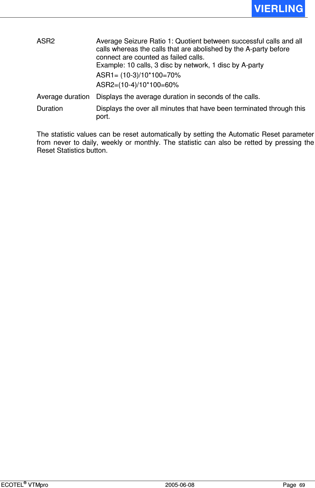
VIERLING Communications ECVTM-PRO Cellular Gateway System User Manual Manual ECOTEL VTMpro 1 1
VIERLING Communications GmbH Cellular Gateway System Manual ECOTEL VTMpro 1 1
Contents
- 1. Users Manual Part I
- 2. Users Manual Part II
- 3. Users Manual Part III
Users Manual Part III
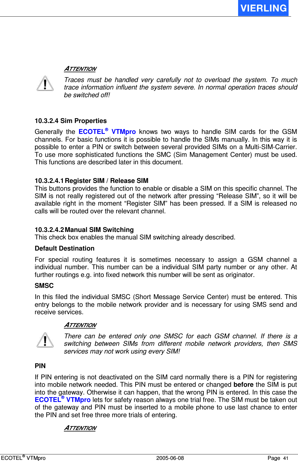
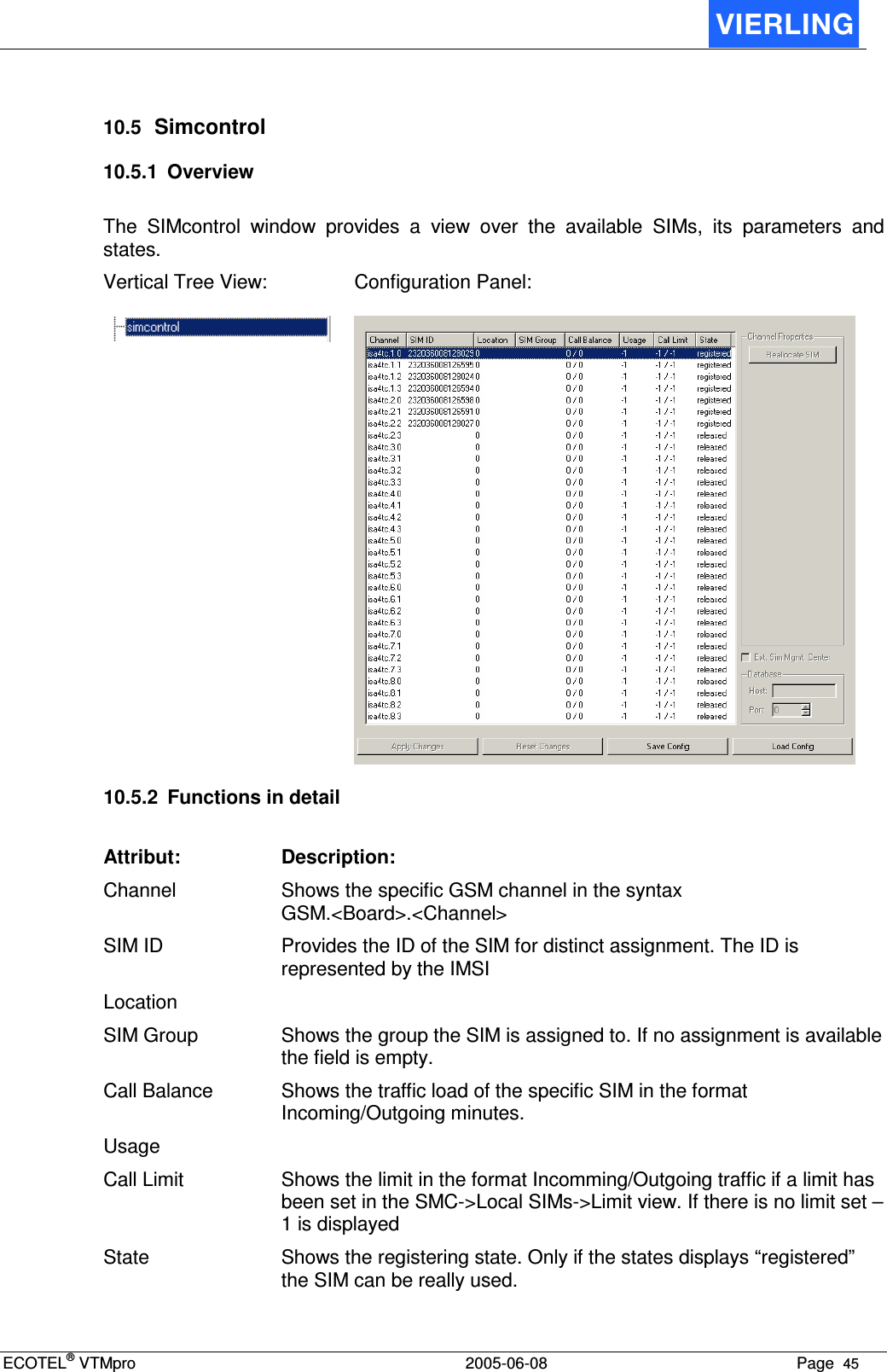
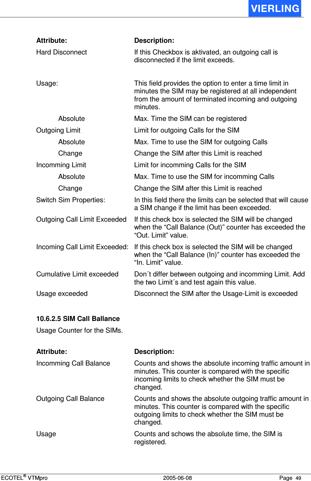
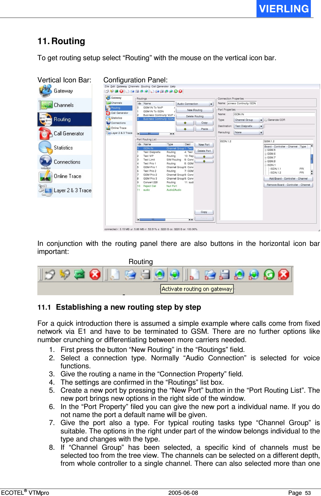
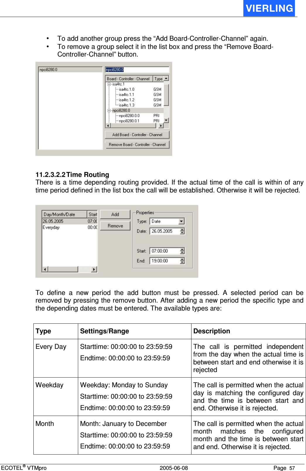
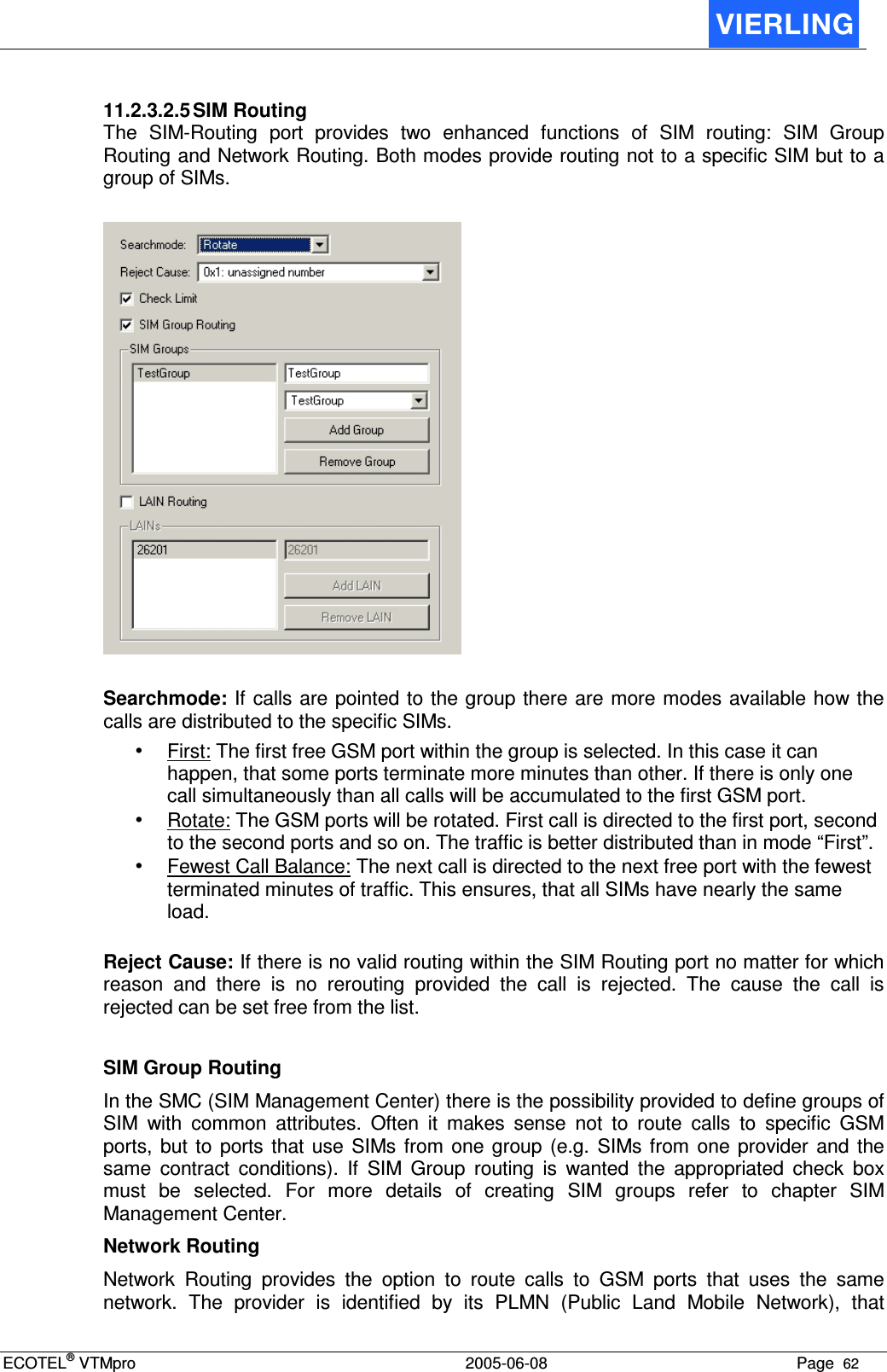
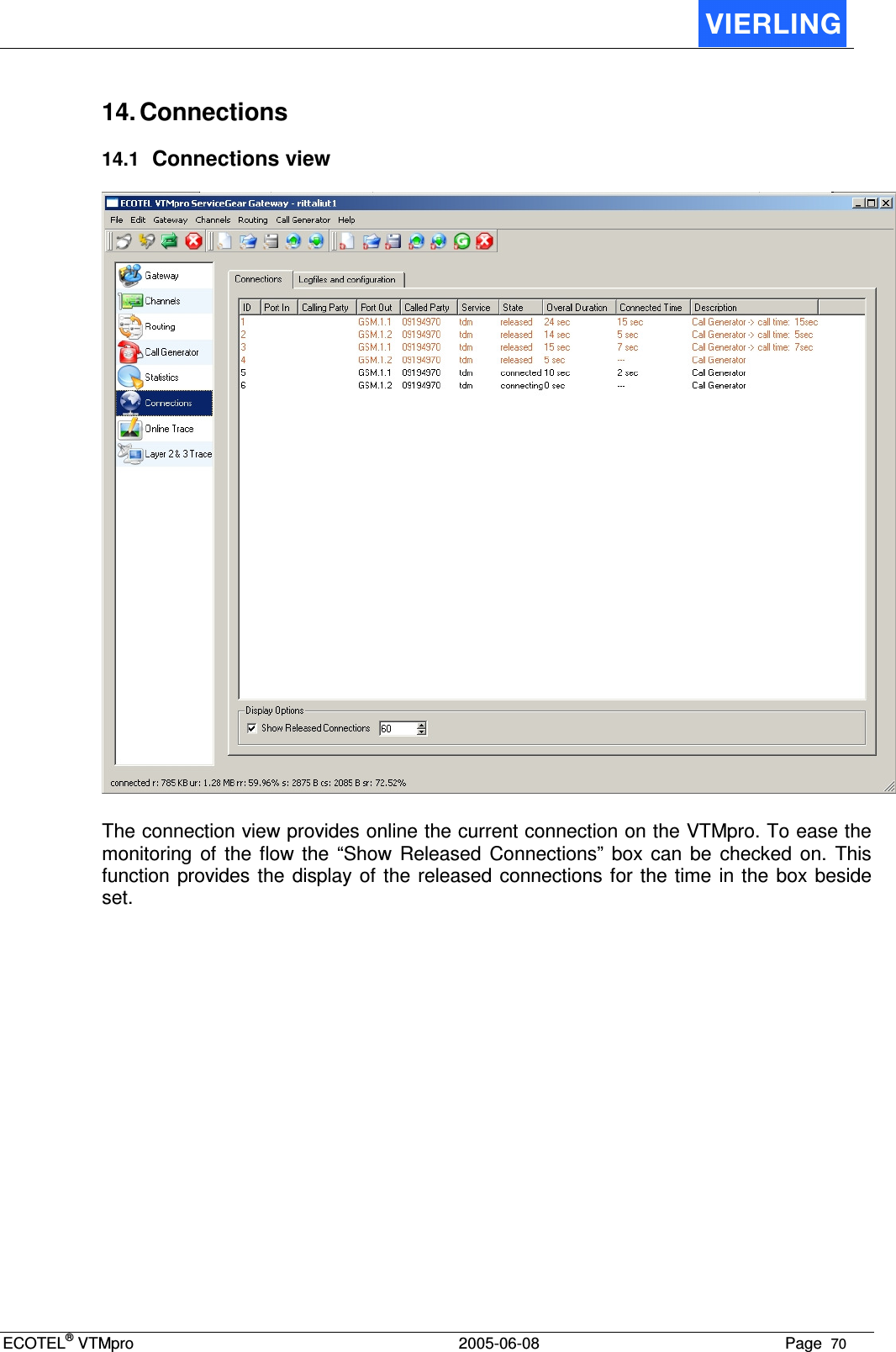
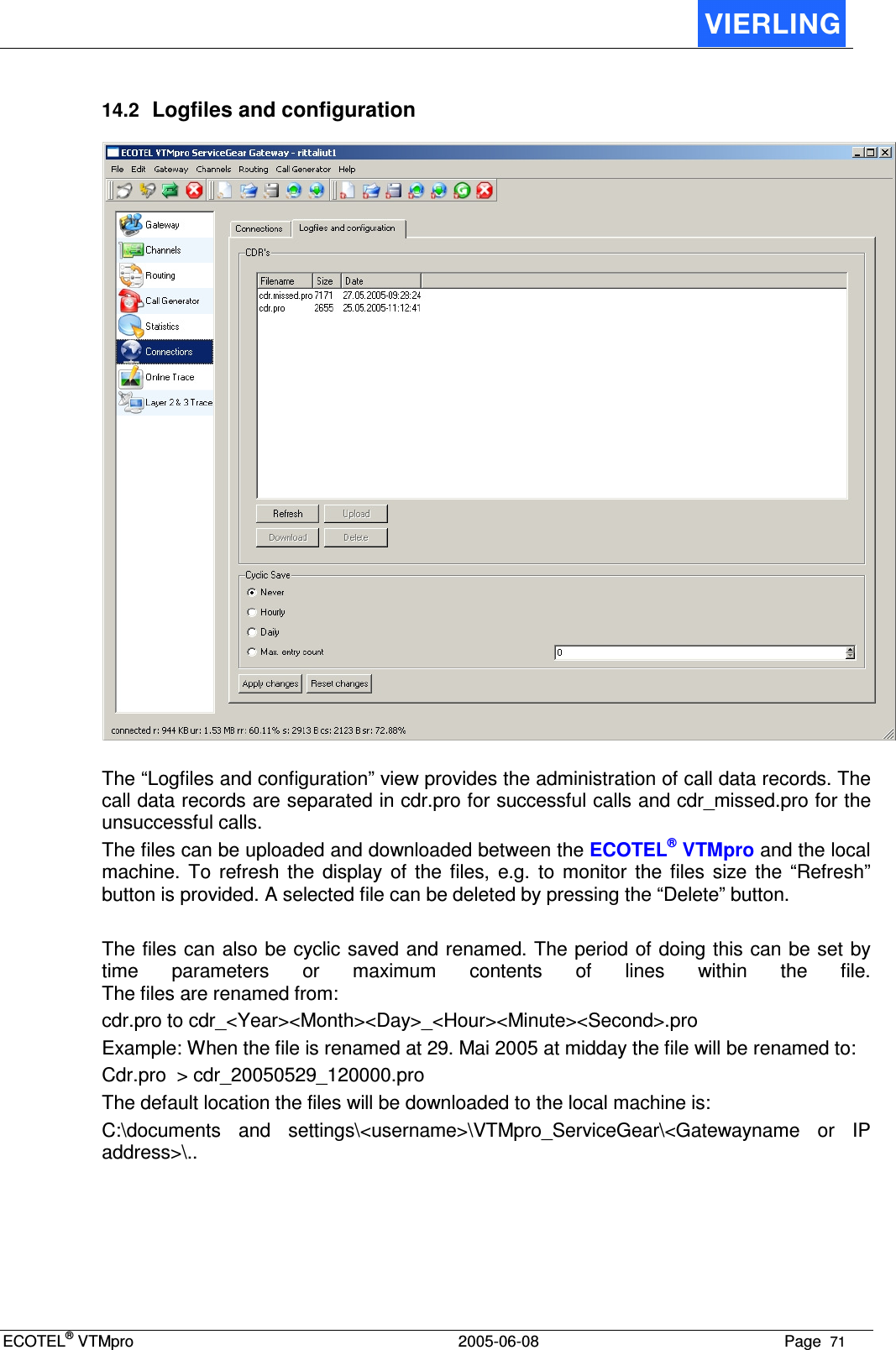
![ECOTEL® VTMpro 2005-06-08 Page 59 List Box In the list box the created conversions are shown. Its just for information and overview: Attribute: Description: Nr. Type Shows the numbering types selected in properties Input Filer Shows the reserved input filter Conversion Shows the applied conversion for the selected filter string Another filter entry can be added by using the “Add” button. In the same way a entry can be removed by selecting it and pressing the “Remove” button. Properties Number Type Within ISDN protocol there is a attribute for called and calling numbers available. The manipulating can be limited to a specific type of numbers. Number Type: Explanation Unknown The number type attribute is not used National The number type within ISDN is set to national format International The number type within ISDN is set to international format Input Filter The input filter provides the possibility to search for strings within a string. Normally there are searched for numbers within a called or calling party number but this function is very universal, so it works also with letters. In conjunction with the “Conversion” function the found strings can be replaced by another string entered in the “Conversion” part. For search mechanism the “Regular Expressions” syntax is used. This is a standardized language for filtering in strings and used in informatics at all. The syntax is as following: Pattern: Description: Example Input Search Expression Found <string> Finds exact the given string 017345678 345 345 . Finds exact one arbitrary sign 01735678 .1.3 0173 ? Finds the precede token cero or once 0173173 173? 173 + Finds the precede token once or more 017335678 3+ 33 * Finds the precede token cero or more times 017355678 74*35* 7355 [ ] Searches one of the signs included in brackets 01735678 [56] 5](https://usermanual.wiki/VIERLING-Communications/ECVTM-PRO.Users-Manual-Part-III/User-Guide-564537-Page-21.png)
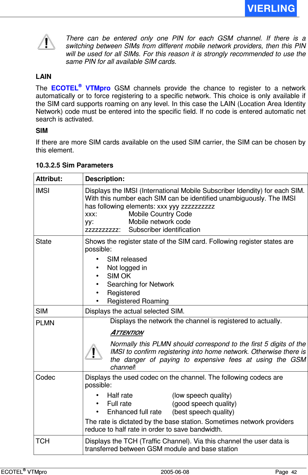
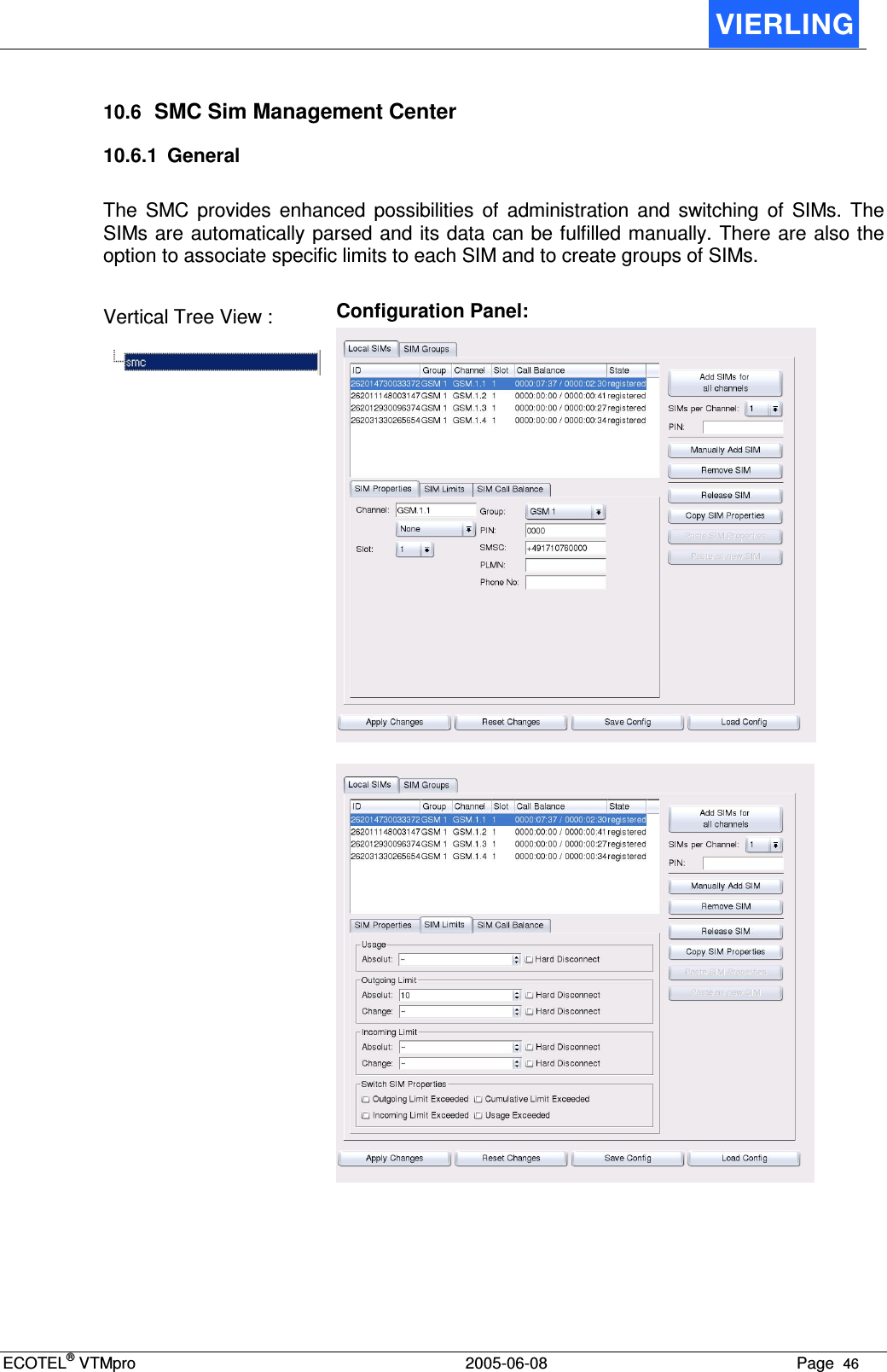
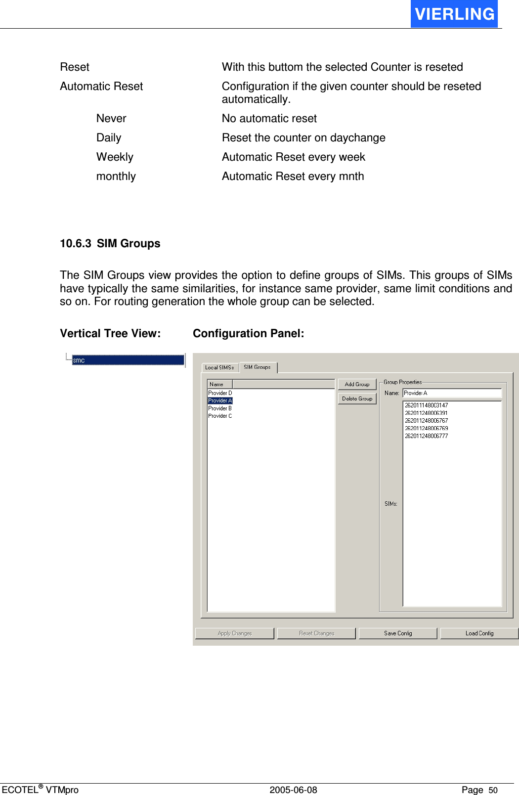
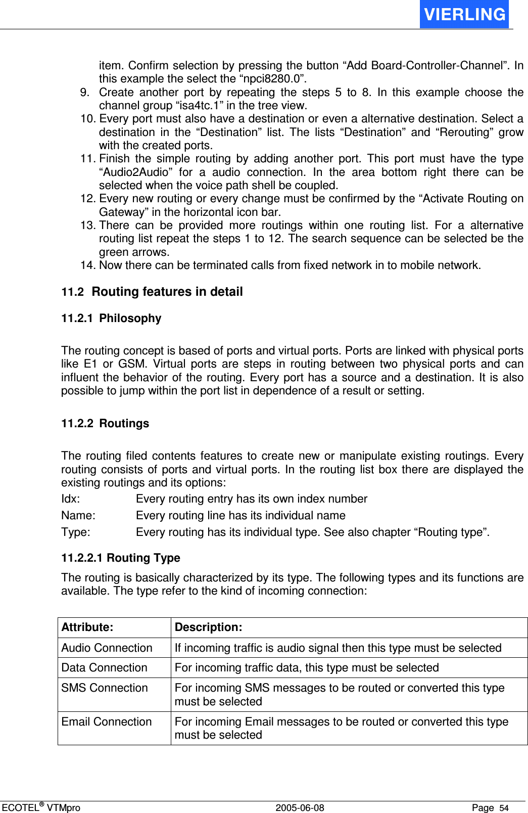
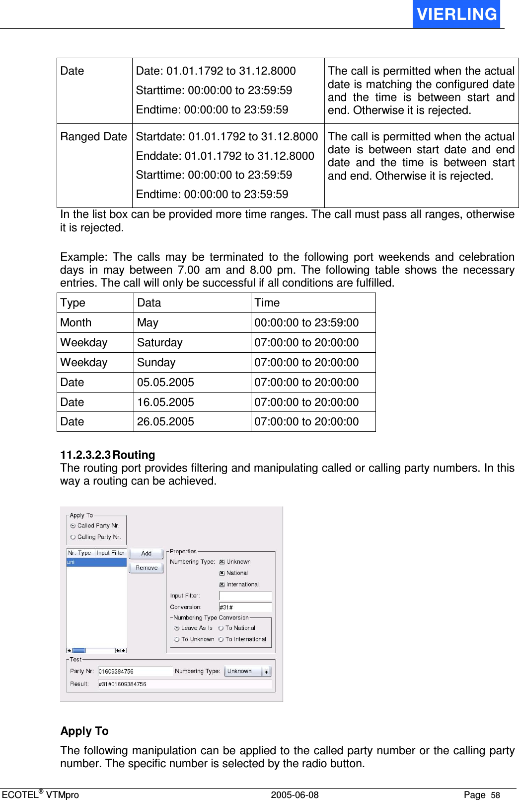
![ECOTEL® VTMpro 2005-06-08 Page 60 [2-4] One of the signs from 2 to 7, it can also be from a to z 01735678 [2-4] 3 [^] No one of the signs included in brackets 23 [^3] 2 ^ Searches a pattern at the beginning of the line 1234321 1^ 1 (at the beginning) $ Searches a pattern at the end of the line 1234321 1$ 1 (at the end) \ Locks the special determination of the following sign +491735678 \+ + Conversion The conversion function provides the possibility to substitute the found string by another given string. The substitution can be entered in the specific conversion field. If there is no suitable string found the string is set before the dialed string. Example1: For CLI suppression the GSM command #31# can be set before the dialed number. In this case there is no search expression needed and in the conversion field the string #31# must be entered. Example2: The international format in the +49… writing shell be changed to 0049…In this case the + must be replaced by the 00 string. Therefore in the search field the \+ must be entered and in the conversion field the 00. Numbering Type Conversion It´s possible to convert the type of Number of the selected number. Field Action Leave as is Don´t change the type of Number To unknown Change the Type of Number to “unknown” To national Change the Type of Number to “national” To international Change the Type of Number to “international” 11.2.3.2.4 Digit Collector The digit collector provides the option to collect a called party number after a connect. The following routing is based on the post dialed number. Only if there is a valid number entered and the routing fits, then the call will go on. Otherwise it is rejected.](https://usermanual.wiki/VIERLING-Communications/ECVTM-PRO.Users-Manual-Part-III/User-Guide-564537-Page-22.png)