VIERLING Communications ECVTM-PRO Cellular Gateway System User Manual Manual ECOTEL VTMpro 1 1
VIERLING Communications GmbH Cellular Gateway System Manual ECOTEL VTMpro 1 1
Contents
- 1. Users Manual Part I
- 2. Users Manual Part II
- 3. Users Manual Part III
Users Manual Part III

ECOTEL® VTMpro 2005-06-08 Page 39
Loudness To GSM
Configures the loudness to the mobile network. The range is 0 (quiet) to 3 (loud).
A
TTENTION
A change becomes not valid before a reboot has been done to the specific
channel.
Loudness to PCM
Configures the loudness to the fixed network. The range is 0 (quiet) to 3 (loud).
A
TTENTION
A change becomes not valid before a reboot has been done to the specific
channel.
Fieldstrength limit
If the received power level under-runs a specific level then the voice quality suffers from it.
So the user can define that specific value. If the level under-runs this level then the
concerning channel will be blocked terminating calls until the value exceeds this level.
10.3.2.2 Channel
This filed contains means affecting one specific channel
Reboot
Pressing this button reboots the specific channel. The channel will be registered out and
the GSM module is switched off and on. Active calls over this channel will be abandoned.
After reboot the channel will register automatically and is available again. This feature can
be useful to resume incorrect channels.
Reregister
Pressing this button registers the channel out of the network an in again. The GSM
module is not switched off. After reregistering the channel is available again. Active calls
will be abandoned. This feature is useful to get a better registration on a other visible base
station with better receive power level or less traffic.
Freeze
This button causes the specific channel to register out and not in anymore. The GSM
module is not switched off. To resume register state the “Reboot” button has to be
pressed. This feature is useful if the base station is overloaded. Then it is possible to
reduce the load by the ECOTEL
®
VTMpro from the basestation.
Switch Off
This button has the same effect like the freeze button plus switching off the GSM module.
Channel Paramters
Provides a set of GSM channel and module parameters
Field strength
Shows the receive power level in a bar and in letters. The value is dBm.

ECOTEL® VTMpro 2005-06-08 Page 40
IMEI
Shows the IMEI of the mounted GSM module. This number characterizes one individual
module.
Manufacturer
Shows the manufacturer of the mounted GSM module.
Model
Shows the model of the mounted GSM module
Revision
Shows the firmware revision of the mounted GSM module
BCCH
Shows the Broadcast Control Channel. The logical channel the basestation sends
parameters necessary for communication.
LAC
Location Area Code or Local Area ID (LAI). Represents the geographical area the mobile
is registered.
BCC
Base Station Color Code
CID
Displays the GSM Cell ID the module is registered to.
10.3.2.3 Layer2Trace
This field provides the possibility to select certain processes at debugging the GSM port.
The meaning of the most used are following:
GREG:
(GSM Registration) Registration information. Interesting at registering problems, to find out
blocked or disturbed sim cards. Also interesting to monitor gathering
cell paramters. Causes continuing trace information even when there
is no call on the channel.
GCON:
(GSM Control)
Provides information about the calling procedure. Causes only trace
information when there is a call establishing or finishing, not during the
call. Interesting to find out problems at establishing calls.
GIF:
(GSM Interface)
Displays the message flow between the controller on the GSM card
and the mounted GSM module. Causes continuing trace information
even when there is no call on the channel.
GSMS:
(GSM SMS interface)
Displays processes concerning SMS receiving and transmitting.
PTS:
(PCM Time Slot)
Displays the coupled time slot from the specific board to the internal
PCM bus.
To get trace information refer also to chapter “Layer2&3 Trace”, because there must
additional switched on the specific channel on debugging level 2.

ECOTEL® VTMpro 2005-06-08 Page 41
A
TTENTION
Traces must be handled very carefully not to overload the system. To much
trace information influent the system severe. In normal operation traces should
be switched off!
10.3.2.4 Sim Properties
Generally the ECOTEL
®
VTMpro knows two ways to handle SIM cards for the GSM
channels. For basic functions it is possible to handle the SIMs manually. In this way it is
possible to enter a PIN or switch between several provided SIMs on a Multi-SIM-Carrier.
To use more sophisticated functions the SMC (Sim Management Center) must be used.
This functions are described later in this document.
10.3.2.4.1 Register SIM / Release SIM
This buttons provides the function to enable or disable a SIM on this specific channel. The
SIM is not really registered out of the network after pressing “Release SIM”, so it will be
available right in the moment “Register SIM” has been pressed. If a SIM is released no
calls will be routed over the relevant channel.
10.3.2.4.2 Manual SIM Switching
This check box enables the manual SIM switching already described.
Default Destination
For special routing features it is sometimes necessary to assign a GSM channel a
individual number. This number can be a individual SIM party number or any other. At
further routings e.g. into fixed network this number will be sent as originator.
SMSC
In this filed the individual SMSC (Short Message Service Center) must be entered. This
entry belongs to the mobile network provider and is necessary for using SMS send and
receive services.
A
TTENTION
There can be entered only one SMSC for each GSM channel. If there is a
switching between SIMs from different mobile network providers, then SMS
services may not work using every SIM!
PIN
If PIN entering is not deactivated on the SIM card normally there is a PIN for registering
into mobile network needed. This PIN must be entered or changed before the SIM is put
into the gateway. Otherwise it can happen, that the wrong PIN is entered. In this case the
ECOTEL
®
VTMpro lets for safety reason always one trial free. The SIM must be taken out
of the gateway and PIN must be inserted to a mobile phone to use last chance to enter
the PIN and set free three more trials of entering.
A
TTENTION

ECOTEL® VTMpro 2005-06-08 Page 42
There can be entered only one PIN for each GSM channel. If there is a
switching between SIMs from different mobile network providers, then this PIN
will be used for all SIMs. For this reason it is strongly recommended to use the
same PIN for all available SIM cards.
LAIN
The ECOTEL
®
VTMpro GSM channels provide the chance to register to a network
automatically or to force registering to a specific network. This choice is only available if
the SIM card supports roaming on any level. In this case the LAIN (Location Area Identity
Network) code must be entered into the specific field. If no code is entered automatic net
search is activated.
SIM
If there are more SIM cards available on the used SIM carrier, the SIM can be chosen by
this element.
10.3.2.5 Sim Parameters
Attribut: Description:
IMSI Displays the IMSI (International Mobile Subscriber Idendity) for each SIM.
With this number each SIM can be identified unambiguously. The IMSI
has following elements: xxx yyy zzzzzzzzzz
xxx: Mobile Country Code
yy: Mobile network code
zzzzzzzzzz: Subscriber identification
State Shows the register state of the SIM card. Following register states are
possible:
•
SIM released
•
Not logged in
•
SIM OK
•
Searching for Network
•
Registered
•
Registered Roaming
SIM Displays the actual selected SIM.
PLMN
Displays the network the channel is registered to actually.
A
TTENTION
Normally this PLMN should correspond to the first 5 digits of the
IMSI to confirm registering into home network. Otherwise there is
the danger of paying to expensive fees at using the GSM
channel!
Codec Displays the used codec on the channel. The following codecs are
possible:
•
Half rate (low speech quality)
•
Full rate (good speech quality)
•
Enhanced full rate (best speech quality)
The rate is dictated by the base station. Sometimes network providers
reduce to half rate in order to save bandwidth.
TCH Displays the TCH (Traffic Channel). Via this channel the user data is
transferred between GSM module and base station
ECOTEL® VTMpro 2005-06-08 Page 43
TADV Displays the TADV (Time Advance). This parameters indicates the
distance between GSM module and base station. One digit represents
about 550 meters. The value range is 0 to 63.
PWR Displays the actual output sending power of the module in dBm
BER Displays the BER (Bit Error Rate). Normally the value should be cero.
Otherwise the are problems in the channel or low receive power level.
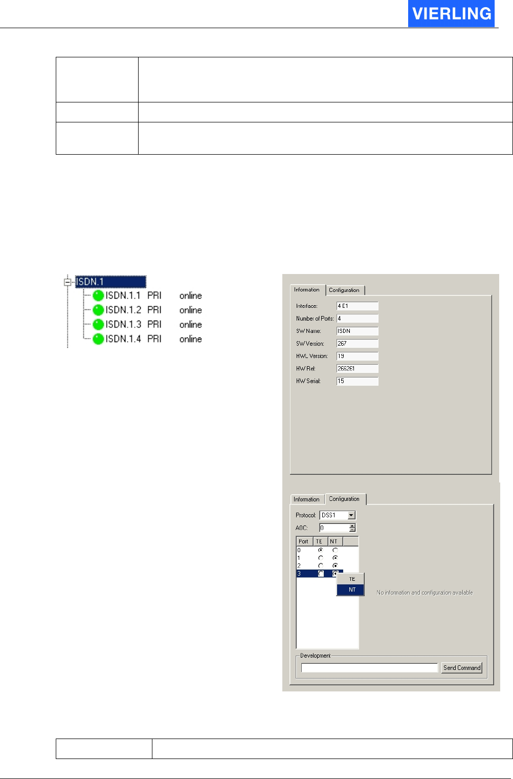
10.4
ISDN
After connecting a port of the ECOTEL
®
VTMpro to any other equipment the
corresponding button in the vertical icon bar must turn green. Otherwise the port can not
be used. If the port will not become active the settings and the cable pinning must be
checked!
Vertical Tree View:
Board Configuration Panel:
10.4.1 Information
Attribut: Description:

ECOTEL® VTMpro 2005-06-08 Page 44
Interface Name of the card. Normally is the name 4E1. Further developments
can also be named different.
Number of Ports Displays the number of available ports. License models can also
generate a different number of physical available and useable ports.
SW Name Name of the running firmware. The name can vary with the set
protocol.
SW Version Version of the installed firmware.
HWL Version Hardware layout version of the mounted board
HW Rel. Release of the installed hardware.
HW Serial Serial number of the installed hardware
10.4.2 Configuration
Attribut: Description:
Protocol This setup allows to choose different protocols running on the card.
Available protocols are:
DSS1: European ISDN signaling
NI1: National ISDN 1 (US standard)
ISUP: Signaling System 7 (SS7)
AOC Provides the possibility to send AOC (Advice Of Charge) information in
NT mode. This feature is not available in general in ISUP mode. When
AOC is selected the value in the specific field determines the time
between two AOC messages are sent.
Port Provides the available ports and its function. The change between NT
(Network Termination) and TE (Terminal Equipment) can be
established be moving the mouse arrow over the radio button,
pressing the right mouse button and selecting TE or NT. This
procedure is for security reason, that the mode is not changed by
chance.
A
TTENTION
After any change the “Apply” button must be pressed and the ECOTEL
®
VTMpro must be rebooted
ECOTEL® VTMpro 2005-06-08 Page 45
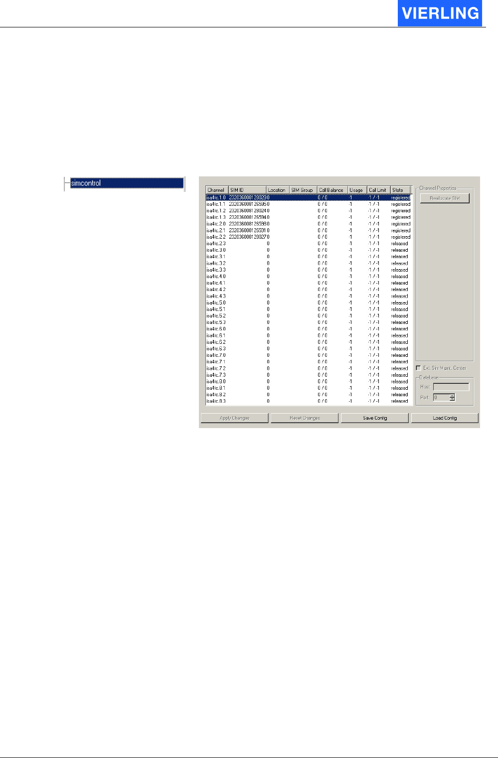
10.5
Simcontrol
10.5.1 Overview
The SIMcontrol window provides a view over the available SIMs, its parameters and
states.
Vertical Tree View: Configuration Panel:
10.5.2 Functions in detail
Attribut: Description:
Channel Shows the specific GSM channel in the syntax
GSM.<Board>.<Channel>
SIM ID Provides the ID of the SIM for distinct assignment. The ID is
represented by the IMSI
Location
SIM Group Shows the group the SIM is assigned to. If no assignment is available
the field is empty.
Call Balance Shows the traffic load of the specific SIM in the format
Incoming/Outgoing minutes.
Usage
Call Limit Shows the limit in the format Incomming/Outgoing traffic if a limit has
been set in the SMC->Local SIMs->Limit view. If there is no limit set –
1 is displayed
State Shows the registering state. Only if the states displays “registered”
the SIM can be really used.
ECOTEL® VTMpro 2005-06-08 Page 46
10.6
SMC Sim Management Center
10.6.1 General
The SMC provides enhanced possibilities of administration and switching of SIMs. The
SIMs are automatically parsed and its data can be fulfilled manually. There are also the
option to associate specific limits to each SIM and to create groups of SIMs.
Vertical Tree View : Configuration Panel:
ECOTEL® VTMpro 2005-06-08 Page 47
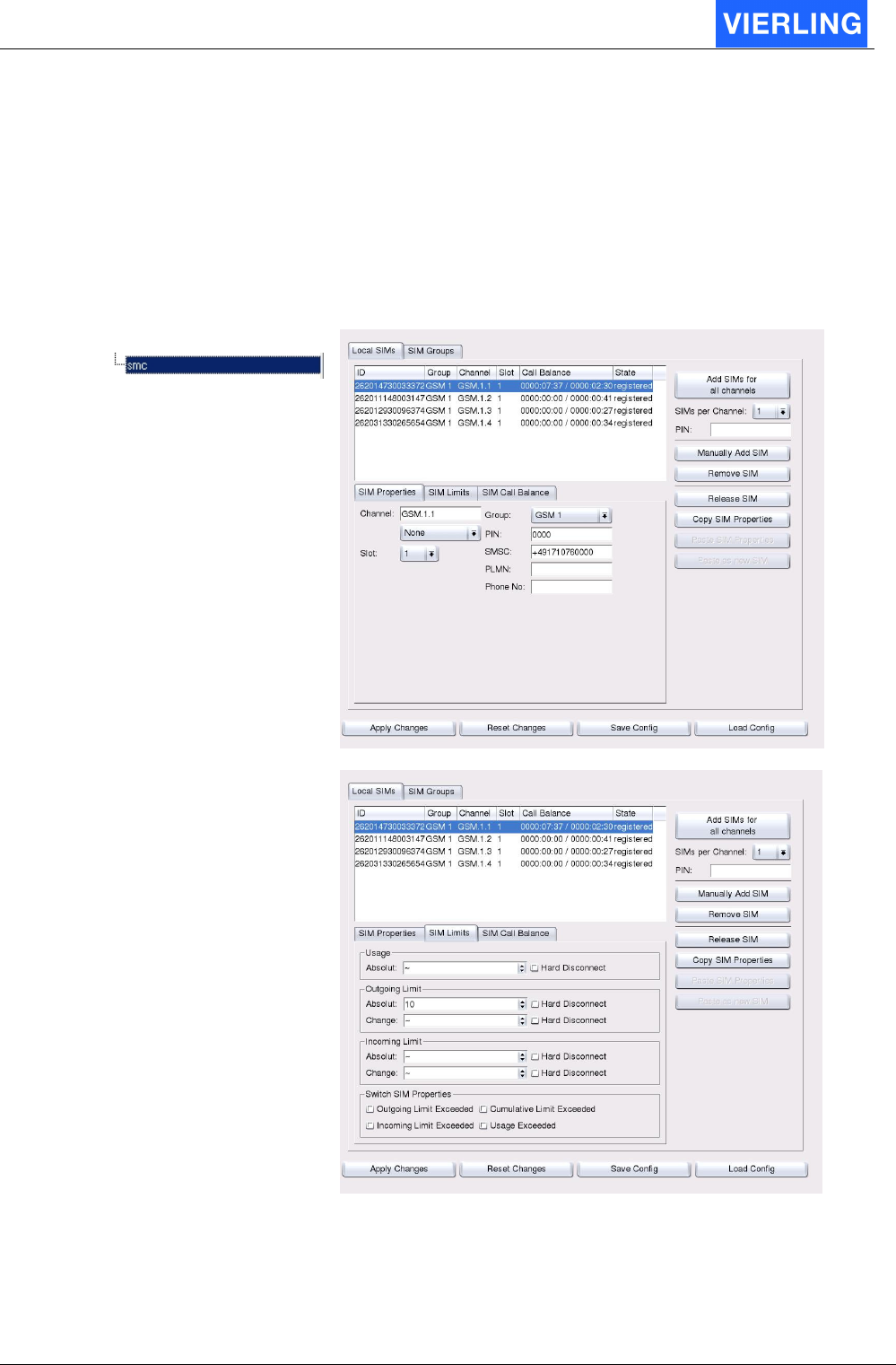
10.6.2 Local SIMs
The Local SIMs sheet provides administration of the local SIMs and its traffic limits.
10.6.2.1 Sim Data Status Box
The main box lists all in the system available SIMs, the active ones and also the SIMs on
reserved positions.
The provided information are:
Attribute Description
Idx: Index number oft the specific SIM
Id: Individual identification number represented by the IMSI
Group: The group the SIM is assigned to (refer to SIM groups view)
Channel: The GSM channel the SIM is put in
Slot: The position the SIM is put in the SIM carrier of the GSM channel
Call Balance: The accumulated traffic of the SIM separated in Incoming/Outgoing
State: The working condition the SIM is at the moment
10.6.2.2 Manual SIM adding
The buttons on the right side of the SMC – Local SIMs view provide to add SIMs
manually.
Attribute: Description:
Add SIMs for all
channels
This button provides the option to insert SIMs for all available GSM
channels. The parameters of the SIMs will be filled with default values.
This values can be corrected manually or will be partly updated when
the SIM is registered.

ECOTEL® VTMpro 2005-06-08 Page 48
SIMs per channel
Together with the “Add SIMs for all channels” there can be set how
many SIMs are provided per channel.
PIN: There can be set a PIN value for all added SIMs
Manually Add
SIM
Using this button there can be added one single SIM. The parameters
of the SIMs will be filled with default values. This values can be
corrected manually or will be partly updated when the SIM is
registered.
Remove SIM The selected SIM will be removed by pressing this button.
Release SIM
Copy SIM
Properties
For easier editing parameters for each SIM card there is a copy and
paste function provided. With this function it is for example possible to
copy SIM limits from one SIM and paste it to all others
Paste SIM
Properties
See “Copy SIM Properties”
A
TTENTION
All changes and inputs must be confirmed by the “Apply” button, otherwise
changes will take no affect!
10.6.2.3 SIM Properties
Attribute: Description:
Channel: If a already registered SIM has to be changed by its channel reference
it can be entered here in conjunction with the “Manual Override” check
box or it must be used if a SIM has to be added manually at all.
Slot: The slot can be specified the actual SIM is physically entered in the
SIM carrier of the GSM channel
Group: The SIM can be assigned to a specific group. The group must have be
defined before in the SIM groups view.
PIN: The SIM specific PIN can be entered
SMSC: The number of the SMS Servicecenter the SIM can work with can be
entered here. This is vital for sending and receiving SMS via this SIM.
PLMN: Public Land Mobile Network can be entered to force the SIM to register
only into the specified network. This is useful when the SIM can also
roam into other networks because this can cause tremendous fees.
Phone No: Every SIM has a phone number. For information and to enable
incoming test calls to specific GSM channels the number can be
entered here.
10.6.2.4 SIM Limits
The limit function provides the possibility to use SIMs with monthly limits or limited
minutes contingent at all. It gives also the chance to distribute the total call traffic to more
SIMs.

ECOTEL® VTMpro 2005-06-08 Page 49
Attribute: Description:
Hard Disconnect If this Checkbox is aktivated, an outgoing call is
disconnected if the limit exceeds.
Usage: This field provides the option to enter a time limit in
minutes the SIM may be registered at all independent
from the amount of terminated incoming and outgoing
minutes.
Absolute Max. Time the SIM can be registered
Outgoing Limit Limit for outgoing Calls for the SIM
Absolute Max. Time to use the SIM for outgoing Calls
Change Change the SIM after this Limit is reached
Incomming Limit Limit for incomming Calls for the SIM
Absolute Max. Time to use the SIM for incomming Calls
Change Change the SIM after this Limit is reached
Switch Sim Properties: In this field there the limits can be selected that will cause
a SIM change if the limit has been exceeded.
Outgoing Call Limit Exceeded If this check box is selected the SIM will be changed
when the “Call Balance (Out)” counter has exceeded the
“Out. Limit” value.
Incoming Call Limit Exceeded:
If this check box is selected the SIM will be changed
when the “Call Balance (In)” counter has exceeded the
“In. Limit” value.
Cumulative Limit exceeded Don´t differ between outgoing and incomming Limit. Add
the two Limit´s and test again this value.
Usage exceeded Disconnect the SIM after the Usage-Limit is exceeded
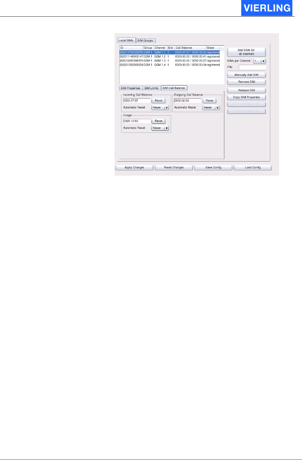
10.6.2.5 SIM Call Ballance
Usage Counter for the SIMs.
Attribute: Description:
Incomming Call Balance Counts and shows the absolute incoming traffic amount in
minutes. This counter is compared with the specific
incoming limits to check whether the SIM must be
changed.
Outgoing Call Balance Counts and shows the absolute outgoing traffic amount in
minutes. This counter is compared with the specific
outgoing limits to check whether the SIM must be
changed.
Usage Counts and schows the absolute time, the SIM is
registered.
ECOTEL® VTMpro 2005-06-08 Page 50
Reset With this buttom the selected Counter is reseted
Automatic Reset Configuration if the given counter should be reseted
automatically.
Never No automatic reset
Daily Reset the counter on daychange
Weekly Automatic Reset every week
monthly Automatic Reset every mnth
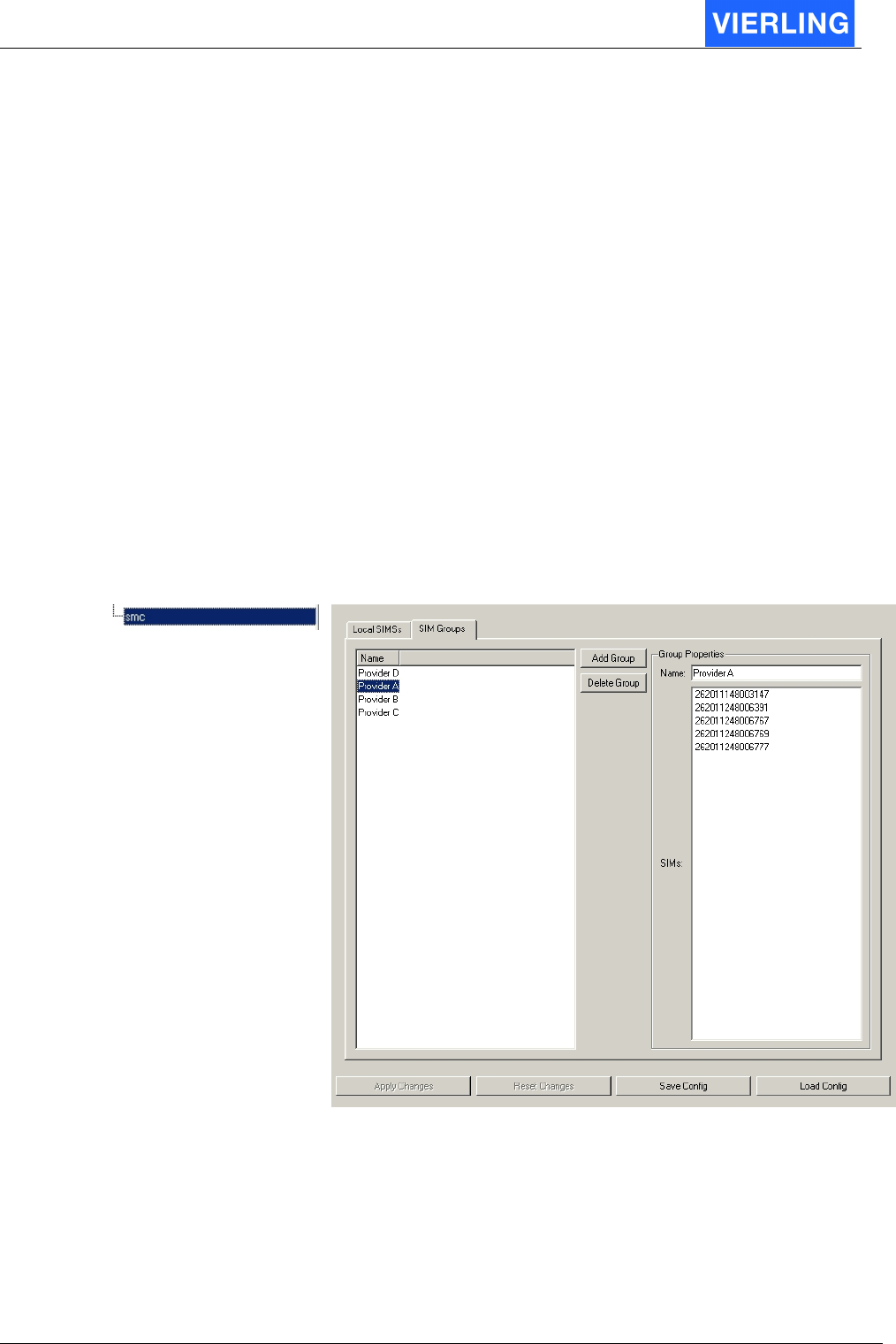
10.6.3 SIM Groups
The SIM Groups view provides the option to define groups of SIMs. This groups of SIMs
have typically the same similarities, for instance same provider, same limit conditions and
so on. For routing generation the whole group can be selected.
Vertical Tree View: Configuration Panel:

ECOTEL® VTMpro 2005-06-08 Page 51
10.6.3.1 Overview
For adding a new group the following steps have to be fulfilled:
1. Press the button “Add group”.
2. Enter a name for the group in the Group Properties -> Name field.
3. Repeat the steps 1 and 2 as often as new groups wanted
4. If a group must be removed select the group in the SIM Groups -> Name list and
press the button “Delete Group”.
5. To add SIMs to the specific groups switch to the Local SIMs view
6. Select a SIM in the list box
7. Assign the selected SIM to a group by the Local SIMs->SIM->Groups function.
8. Repeat step 7 until all SIMs that have to be assigned are done.
9. Use the groups in routing by selecting a group in Routing -> Port Properties -> SIM
Routing -> SIM Group Routing -> Add Group.

ECOTEL® VTMpro 2005-06-08 Page 52
10.6.3.2 Functions in detail
Attribute: Description:
Name Lists all the already defined groups
Add Group For adding a new group this button must be pressed.
Delete Group If a group is selected in the SIM Groups – Name view it can be
deleted by pressing this button.
Group Properties -
Name
IN order to create a new group the groups name must be entered
here. A already defined groups name can be changed also if the
specific group is selected in the SIM Groups – Name view.
Group Properties -
SIMs
Lists all SIMs that belong to the selected group. The SIMs can be
assigned to a group in the Local SIMs -> SIM -> Group view.
ECOTEL® VTMpro 2005-06-08 Page 53
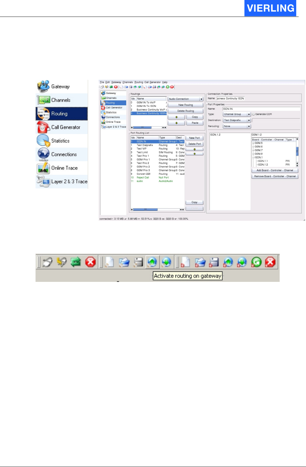
11. Routing
To get routing setup select “Routing” with the mouse on the vertical icon bar.
Vertical Icon Bar: Configuration Panel:
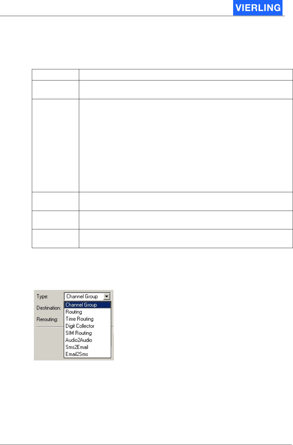
In conjunction with the routing panel there are also buttons in the horizontal icon bar
important:
Routing
11.1
Establishing a new routing step by step
For a quick introduction there is assumed a simple example where calls come from fixed
network via E1 and have to be terminated to GSM. There are no further options like
number crunching or differentiating between more carriers needed.
1. First press the button “New Routing” in the “Routings” field.
2. Select a connection type. Normally “Audio Connection” is selected for voice
functions.
3. Give the routing a name in the “Connection Property” field.
4. The settings are confirmed in the “Routings” list box.
5. Create a new port by pressing the “New Port” button in the “Port Routing List”. The
new port brings new options in the right side of the window.
6. In the “Port Property” filed you can give the new port a individual name. If you do
not name the port a default name will be given.
7. Give the port also a type. For typical routing tasks type “Channel Group” is
suitable. The options in the right under part of the window belongs individual to the
type and changes with the type.
8. If “Channel Group” has been selected, a specific kind of channels must be
selected too from the tree view. The channels can be selected on a different depth,
from whole controller to a single channel. There can also selected more than one

ECOTEL® VTMpro 2005-06-08 Page 54
item. Confirm selection by pressing the button “Add Board-Controller-Channel”. In
this example the select the “npci8280.0”.
9. Create another port by repeating the steps 5 to 8. In this example choose the
channel group “isa4tc.1” in the tree view.
10. Every port must also have a destination or even a alternative destination. Select a
destination in the “Destination” list. The lists “Destination” and “Rerouting” grow
with the created ports.
11. Finish the simple routing by adding another port. This port must have the type
“Audio2Audio” for a audio connection. In the area bottom right there can be
selected when the voice path shell be coupled.
12. Every new routing or every change must be confirmed by the “Activate Routing on
Gateway” in the horizontal icon bar.
13. There can be provided more routings within one routing list. For a alternative
routing list repeat the steps 1 to 12. The search sequence can be selected be the
green arrows.
14. Now there can be terminated calls from fixed network in to mobile network.
11.2
Routing features in detail
11.2.1 Philosophy
The routing concept is based of ports and virtual ports. Ports are linked with physical ports
like E1 or GSM. Virtual ports are steps in routing between two physical ports and can
influent the behavior of the routing. Every port has a source and a destination. It is also
possible to jump within the port list in dependence of a result or setting.
11.2.2 Routings
The routing filed contents features to create new or manipulate existing routings. Every
routing consists of ports and virtual ports. In the routing list box there are displayed the
existing routings and its options:
Idx: Every routing entry has its own index number
Name: Every routing line has its individual name
Type: Every routing has its individual type. See also chapter “Routing type”.
11.2.2.1 Routing Type
The routing is basically characterized by its type. The following types and its functions are
available. The type refer to the kind of incoming connection:
Attribute: Description:
Audio Connection If incoming traffic is audio signal then this type must be selected
Data Connection For incoming traffic data, this type must be selected
SMS Connection For incoming SMS messages to be routed or converted this type
must be selected
Email Connection For incoming Email messages to be routed or converted this type
must be selected

ECOTEL® VTMpro 2005-06-08 Page 55
11.2.2.2 New Routing -Delete Routing – Copy –Paste – Sequence
Attribute: Description:
New Routing: To create a new routing this button must be pressed. For
confirmation of a new routing in the list box a raw line must be
visible.
Delete Routing: To delete a routing the specific line within the table must be
selected and the delete button must be pressed.
Copy: Routings can also be copied. To copy a routing the specific line
must be selected and the “Copy” button must be pressed. See also
“Paste”.
Paste: A earlier copied routing line can be inserted by pressing “Paste”.
The details of the routing can be adapted afterwards. See also
“Arrows – Sequence”
Arrows – Sequence The routing machine handles the list in a sequence. Therefore
sometimes it is important in which sequence the routing is stored in
the list. To change the sequence the green buttons can be used.
11.2.2.3 Connection Properties
The connection property is just the name of the routing. If no name is given the ECOTEL
®
VTMpro provides a automatic generated name.
11.2.3 Port Routing List
Contents of the list box:
Attribute: Description:
Idx Every routing port gets its own index number
Name Every port can be assigned a name. The name has to be entered in the
“Name” input in the “Port Properties” field. If no name is provided the system
assignes its own name. Anyway this name has to be used for further
references.
Type Shows the type of the specific port. The type has to be selected in the “Type”
input in the “Port Properties” field.
Destination
Specifies the next port the routing machine jumps to if the actual port has
finished its job. If the jobs result are not valid the Rerouting is accessed. The
destination has to be selected in the “Destination” input in the “Port
Properties” field.
Rerouting The rerouting provides a alternative if the default destination can not be
taken. The rerouting has to be selected in the “Rerouting” input in the “Port
Properties” field.
CDR For administration reason there can be entered a line in to CDR (Call Data
Record) file for every port passed through during the routing. If a entry for the
specific port is wanted the check box in the “Port Properties” has to be
selcted.
ECOTEL® VTMpro 2005-06-08 Page 56
11.2.3.1 Port Properties
The port properties are only visible if a port in the routing list is selected. The lower part of
the options belong fix to a specific port type.
The upper part is fix. The elements are:
Attribute: Description:
Name Provides the possibility of giving every port its individual name. If no
name is provided the system assignes its own name.
Type Every port has its own type. The type influents the behavior of the routing
basically. Available Types are:
•
Channel Group
•
Routing
•
Time Routing
•
Digit Collector
•
Sim Routing
•
Audio2Audio
•
Sms2Email
•
Email2Sms
The detailed functions of the specific types are described below.
Destination Provides the possibility to enter the next port to manage after the actual
has been done.
Rerouting If the default next port, entered in “Destination” has failed a alternative
port can be entered.
Generate CDR
Provides the possibility to generate for each port a individual CDR (Call
Data Record) entry in to the cdr.log file.
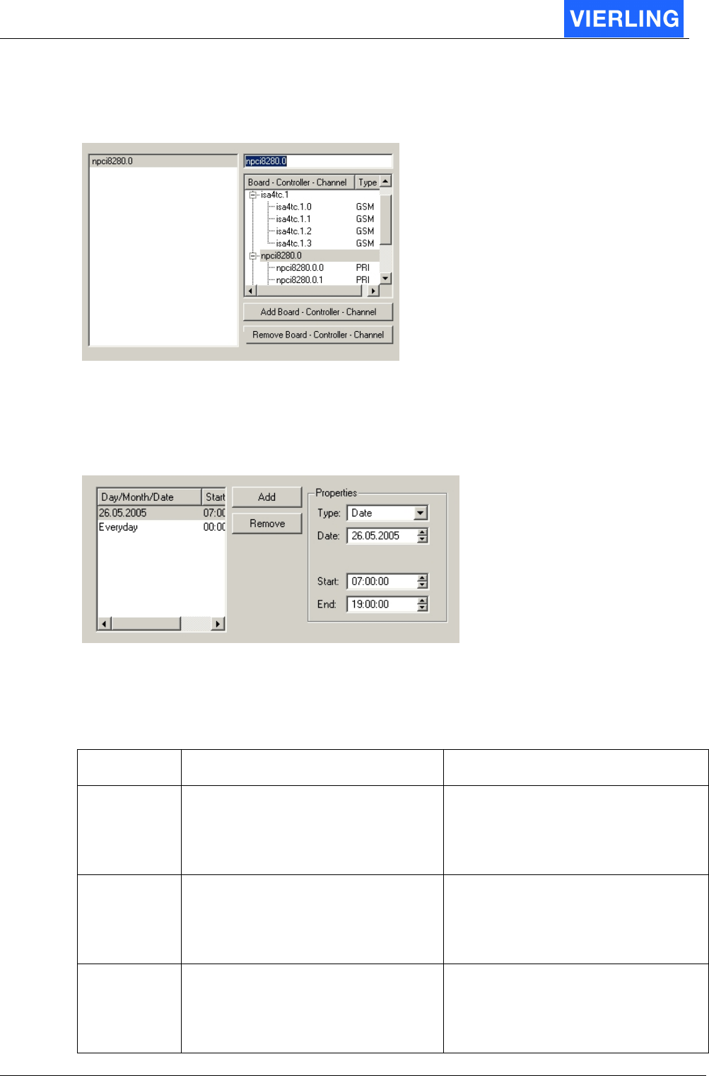
11.2.3.2 Channel types in detail
Every port must be assigned a type. This type can be selected from the “Channel Type”
menu:
11.2.3.2.1 Channel Group
To receive connections from extern or terminate them to external, the channel group is the
necessary type. There can be selected all available ports. This types are displayed in the
“Board-Controller-Channel” list view. To add a new port to a empty list the following steps
must be done:
•
Any type of board, controller or channel must be selected in the tree view.
•
The “Add Board-Controller-Channel” must be pressed. The selection is now visible
in the list box.
ECOTEL® VTMpro 2005-06-08 Page 57
•
To add another group press the “Add Board-Controller-Channel” again.
•
To remove a group select it in the list box and press the “Remove Board-
Controller-Channel” button.
11.2.3.2.2 Time Routing
There is a time depending routing provided. If the actual time of the call is within of any
time period defined in the list box the call will be established. Otherwise it will be rejected.
To define a new period the add button must be pressed. A selected period can be
removed by pressing the remove button. After adding a new period the specific type and
the depending dates must be entered. The available types are:
Type Settings/Range Description
Every Day Starttime: 00:00:00 to 23:59:59
Endtime: 00:00:00 to 23:59:59
The call is permitted independent
from the day when the actual time is
between start and end otherwise it is
rejected
Weekday Weekday: Monday to Sunday
Starttime: 00:00:00 to 23:59:59
Endtime: 00:00:00 to 23:59:59
The call is permitted when the actual
day is matching the configured day
and the time is between start and
end. Otherwise it is rejected.
Month Month: January to December
Starttime: 00:00:00 to 23:59:59
Endtime: 00:00:00 to 23:59:59
The call is permitted when the actual
month matches the configured
month and the time is between start
and end. Otherwise it is rejected.
ECOTEL® VTMpro 2005-06-08 Page 58
Date Date: 01.01.1792 to 31.12.8000
Starttime: 00:00:00 to 23:59:59
Endtime: 00:00:00 to 23:59:59
The call is permitted when the actual
date is matching the configured date
and the time is between start and
end. Otherwise it is rejected.
Ranged Date
Startdate: 01.01.1792 to 31.12.8000
Enddate: 01.01.1792 to 31.12.8000
Starttime: 00:00:00 to 23:59:59
Endtime: 00:00:00 to 23:59:59
The call is permitted when the actual
date is between start date and end
date and the time is between start
and end. Otherwise it is rejected.
In the list box can be provided more time ranges. The call must pass all ranges, otherwise
it is rejected.
Example: The calls may be terminated to the following port weekends and celebration
days in may between 7.00 am and 8.00 pm. The following table shows the necessary
entries. The call will only be successful if all conditions are fulfilled.
Type Data Time
Month May 00:00:00 to 23:59:00
Weekday Saturday 07:00:00 to 20:00:00
Weekday Sunday 07:00:00 to 20:00:00
Date 05.05.2005 07:00:00 to 20:00:00
Date 16.05.2005 07:00:00 to 20:00:00
Date 26.05.2005 07:00:00 to 20:00:00
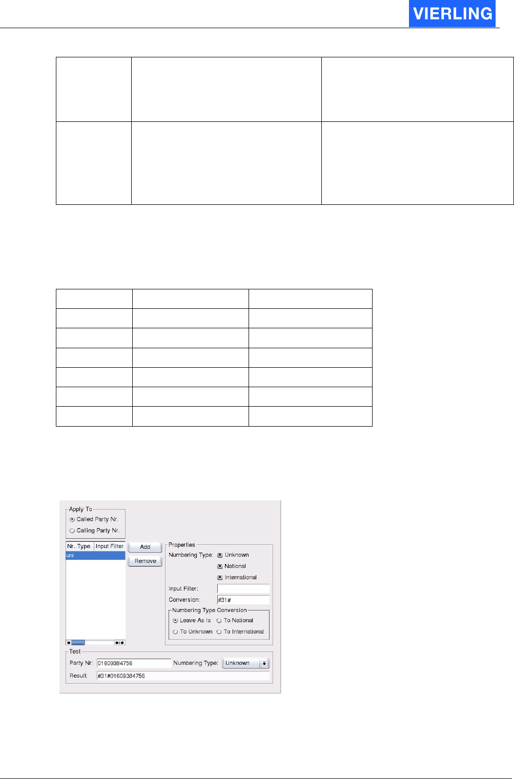
11.2.3.2.3 Routing
The routing port provides filtering and manipulating called or calling party numbers. In this
way a routing can be achieved.
Apply To
The following manipulation can be applied to the called party number or the calling party
number. The specific number is selected by the radio button.

ECOTEL® VTMpro 2005-06-08 Page 59
List Box
In the list box the created conversions are shown. Its just for information and overview:
Attribute: Description:
Nr. Type Shows the numbering types selected in properties
Input Filer Shows the reserved input filter
Conversion Shows the applied conversion for the selected filter string
Another filter entry can be added by using the “Add” button. In the same way a entry can
be removed by selecting it and pressing the “Remove” button.
Properties
Number Type
Within ISDN protocol there is a attribute for called and calling numbers available. The
manipulating can be limited to a specific type of numbers.
Number Type: Explanation
Unknown The number type attribute is not used
National The number type within ISDN is set to national format
International The number type within ISDN is set to international format
Input Filter
The input filter provides the possibility to search for strings within a string. Normally there
are searched for numbers within a called or calling party number but this function is very
universal, so it works also with letters. In conjunction with the “Conversion” function the
found strings can be replaced by another string entered in the “Conversion” part. For
search mechanism the “Regular Expressions” syntax is used. This is a standardized
language for filtering in strings and used in informatics at all. The syntax is as following:
Pattern: Description: Example
Input Search
Expression
Found
<string> Finds exact the given string 017345678 345 345
. Finds exact one arbitrary sign 01735678 .1.3 0173
? Finds the precede token cero or once 0173173 173? 173
+ Finds the precede token once or more 017335678 3+ 33
* Finds the precede token cero or more
times
017355678 74*35* 7355
[ ] Searches one of the signs included in
brackets
01735678 [56] 5

ECOTEL® VTMpro 2005-06-08 Page 60
[2-4] One of the signs from 2 to 7, it can
also be from a to z
01735678 [2-4] 3
[^] No one of the signs included in
brackets
23 [^3] 2
^ Searches a pattern at the beginning of
the line
1234321 1^ 1 (at the
beginning)
$ Searches a pattern at the end of the
line
1234321 1$ 1 (at the end)
\ Locks the special determination of the
following sign
+491735678 \+ +
Conversion
The conversion function provides the possibility to substitute the found string by another
given string. The substitution can be entered in the specific conversion field. If there is no
suitable string found the string is set before the dialed string.
Example1: For CLI suppression the GSM command #31# can be set before the dialed
number. In this case there is no search expression needed and in the conversion field the
string #31# must be entered.
Example2: The international format in the +49… writing shell be changed to 0049…In this
case the + must be replaced by the 00 string. Therefore in the search field the \+ must be
entered and in the conversion field the 00.
Numbering Type Conversion
It´s possible to convert the type of Number of the selected number.
Field Action
Leave as is Don´t change the type of Number
To unknown Change the Type of Number to “unknown”
To national Change the Type of Number to “national”
To international Change the Type of Number to “international”
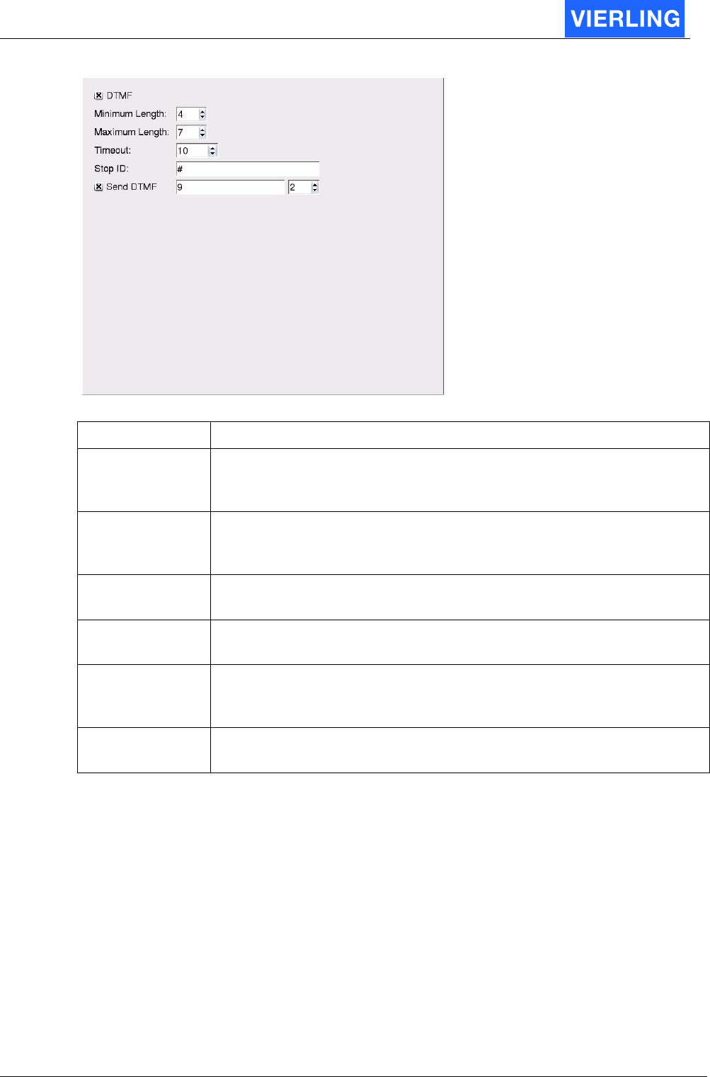
11.2.3.2.4 Digit Collector
The digit collector provides the option to collect a called party number after a connect. The
following routing is based on the post dialed number. Only if there is a valid number
entered and the routing fits, then the call will go on. Otherwise it is rejected.
ECOTEL® VTMpro 2005-06-08 Page 61
Attribute: Description:
DTMF If the check box is selected, the collector accepts digit only in band in
DTMF tone format. Otherwise the digits are expected within the
signaling path.
Minimum Length The digit collector must decide the moment the number is complete.
The minimum length must be always reached before the number can
be complete.
Maximum Length
If the maximum length is reached the collector considers the number
as complete
Timeout If the count of the numbers is within min and max the number is
considered to be complete if the timeout is reached.
Stop ID If the number is between minimum and maximum it´s possibel with the
“Stop ID” to stop the Timeout. The connection to the destination is
started. The Stop ID is not deleted from the Called Party Number!
Send DTMF If the check box is selected, the collector sends the number as DTMF-
Signal X sekonds after the entry.
ECOTEL® VTMpro 2005-06-08 Page 62
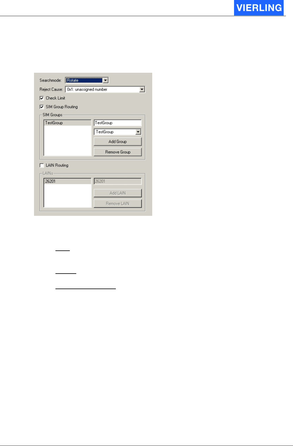
11.2.3.2.5 SIM Routing
The SIM-Routing port provides two enhanced functions of SIM routing: SIM Group
Routing and Network Routing. Both modes provide routing not to a specific SIM but to a
group of SIMs.
Searchmode: If calls are pointed to the group there are more modes available how the
calls are distributed to the specific SIMs.
•
First: The first free GSM port within the group is selected. In this case it can
happen, that some ports terminate more minutes than other. If there is only one
call simultaneously than all calls will be accumulated to the first GSM port.
•
Rotate: The GSM ports will be rotated. First call is directed to the first port, second
to the second ports and so on. The traffic is better distributed than in mode “First”.
•
Fewest Call Balance: The next call is directed to the next free port with the fewest
terminated minutes of traffic. This ensures, that all SIMs have nearly the same
load.
Reject Cause: If there is no valid routing within the SIM Routing port no matter for which
reason and there is no rerouting provided the call is rejected. The cause the call is
rejected can be set free from the list.
SIM Group Routing
In the SMC (SIM Management Center) there is the possibility provided to define groups of
SIM with common attributes. Often it makes sense not to route calls to specific GSM
ports, but to ports that use SIMs from one group (e.g. SIMs from one provider and the
same contract conditions). If SIM Group routing is wanted the appropriated check box
must be selected. For more details of creating SIM groups refer to chapter SIM
Management Center.
Network Routing
Network Routing provides the option to route calls to GSM ports that uses the same
network. The provider is identified by its PLMN (Public Land Mobile Network), that
ECOTEL® VTMpro 2005-06-08 Page 63
consists of MCC (Mobile Country Code) plus MNC (Mobile Network Code). This code can
be also viewed in the information sheet of every GSM channel. There can be provided
more codes to cover even roaming conditions if wanted.
A
TTENTION
Some SIMs provide the option of international or even national roaming. When
there is roaming active the PLMN differs from the home network PLMN. In this
case there will be no calls directed to the affected channels in Network Routing
mode if there is only the PLMN from the home network provided. Roaming can
be prohibited by entering a PLMN code at the SIM properties within a specific
GSM channel.
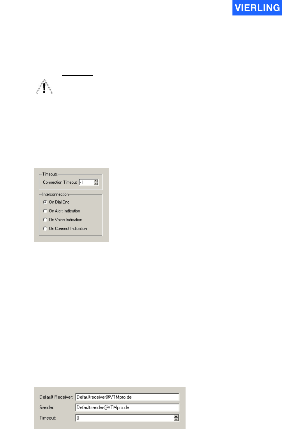
11.2.3.2.6 Audio2Audio
For audio connections the is a coupling of time slots at a specific moment necessary. This
coupling is provided by the Audio2Audio port. This port is the terminating port of any
routing of voice calls.
Timeout: This parameter provides the option to cancel a connection after a specific time.
The value is set in seconds. If the parameter is set to –1 then there is no timeout selected.
The time starts counting after the Audio2Audio port is reached within the routing and
stopped when connect to the b-party is performed.
Interconnection: The exact moment of coupling the time slots during establishing a
connection can be selected.:
•
On Dial End: The voice is coupled when dialing has finished and before first alert.
•
On Alert Indication: The voice is coupled after first alert has been recognized.
•
On Voice Indication: The timeslots are coupled when there has a in band voice
message recognized. Voice is defined a in band message that is not typically a
alert or busy signaling before connect.
•
On Connect Indication: The voice is coupled when there has been recognized a
connect at the p-party. In this case any in band information will not be transferred
to the a-party.
11.2.3.2.7 Sms2Email
In order to receive SMS, convert and send it as email there is a Sms2Email port provided.
ECOTEL® VTMpro 2005-06-08 Page 64
Attribute: Description:
Default Receiver In the SMS can be set a receiver email address. If no address can be
found within the SMS the ECOTEL
®
VTMpro sends it to the default
receiver address . If whether a address I the SMS can be found nor a
default address is given the SMS can not be sent as email!
Sender In SMS2Email conversion there is no origin email address given. The
sender can set one in the text. If no sender email address is given the
ECOTEL
®
VTMpro sets the default address. If nor a sender address
can be found in the email address nor there is a default, the ECOTEL
®
VTMpro sets the CLI of the origin mobile if provided.
Timeout The timeout in seconds can be set different to cero, when there shell
be made a new attempt when no confirm is received from the mail
server that the email has been sent.
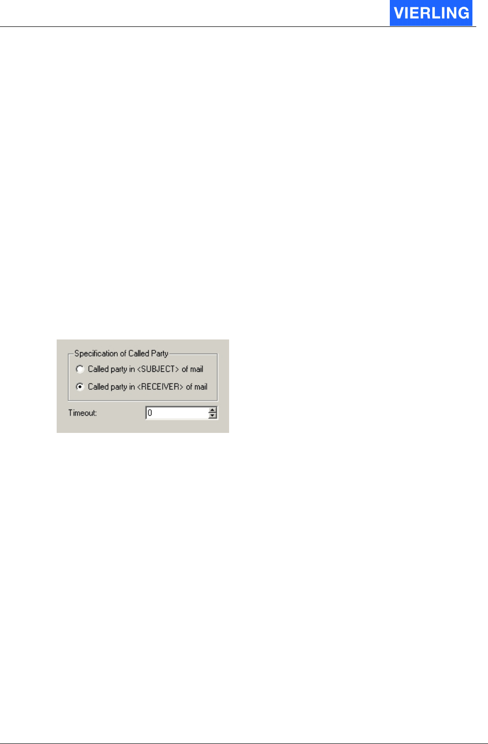
11.2.3.2.8 Email2Sms
In order to receive emails, convert and send it as SMS there is a Email2Sms port
provided.
Attribute: Description:
Called party in
<SUBJECT> of mail
The email that has to be sent as SMS must carry the CLI of the
destination. This can be set in the <SUBJECT” of the email
Called party in
<RECEIVER> of mail
or in the <RECEIVER> field of the email.
Timeout The timeout in seconds can be set different to cero, when there
shell be made a new attempt when no confirm is received from the
provider that the SMS has been sent.
ECOTEL® VTMpro 2005-06-08 Page 65
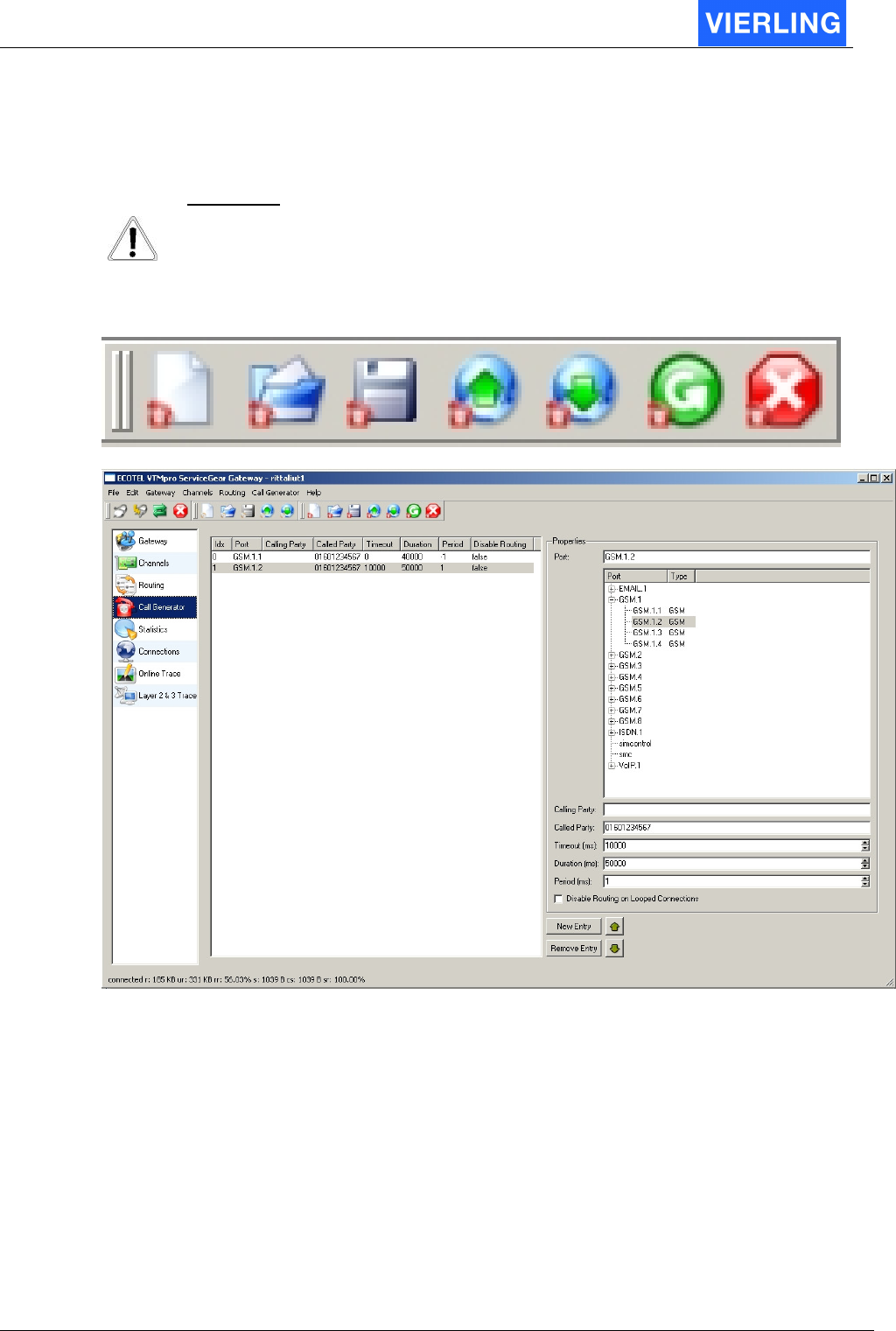
12. Call Generator
The Call Generator is a very useful tool for system setup, maintenance or debugging
A
TTENTION
The Call Generator is only able to simulate calls by signaling not by in band
voice simulation!
New
config
Load
config
Save
config
Upload
config
Download/
Activate
Start
call gen
Stop
call gen
12.1
Overview
The Call Generator provides the option to program a list of calls that will be performed.
The calls can also be looped back and used for routing tests.
To establish a Call Generator entry the following steps must be done:
1. Press the button “New Entry” from the main view. A new entry will be visible in the
list box.
2. Give the entry a optionally name in the properties line.
3. Select a channel from the tree list the call shall be generated from.
4. Give the call a Calling Party e.g. for using it in further routings (A-party).
5. Give the call a Called Party (B-party).
6. Give the call a timeout for start the call. If no delay between start call generator
and start the specific call is wanted the default cero can be let.

ECOTEL® VTMpro 2005-06-08 Page 66
7. Give the call a max. duration. After the duration time the call generator hooks the
call on.
8. If the call shell be performed in period the pause between two repetitions can be
set.
9. If there is a extern loop back available (e.g. cross cable on ISDN-E1) then there
can be set whether the looped back connection shell be routed or not.
10. Press the “Download/Activate” button at the horizontal icon bar
11. Start the Call Generator by pressing the “Start” button at the horizontal icon bar.

ECOTEL® VTMpro 2005-06-08 Page 67
12.2
Functions in details
12.2.1 Horizontal Icon bar
Attribute: Description:
New config Creates a new Call Generator configuration.
Load
config
Loads a already established Call Generator configuration from the
local machine.
Save
config
Saves a Call Generation configuration. The configuration is saved
in XML format on the local machine.
Upload
config
Upload a Call Generator configuration from the ECOTEL
®
VTMpro
in to the maintenance gear for viewing and modification.
Download/
Activate
Loads a established Call Generator configuration down to the
ECOTEL
®
VTMpro and activates it
Start
call gen
Starts the call generator. Action can be monitored simultaneously
at the Connections view or the Layer 2&3 debugging view.
Stop
call gen
Stops the Call Generator. The Call Generator must always be
stopped by the user even when the call has already been finished
by the B party before it can started again.
12.2.2 Elements from main view
Attribute: Description:
List Box The list box shows all configured calls. Arbitrary number of calls
can be programmed. The calls are worked in the sequence of
listing, started with one. The sequence can be manipulated by
using the green up/down arrows.
New Entry A new call entry is established by this button
Remove Entry A selected entry can be removed by pressing this button.
Port The call can be given a optionally a individual name. Essentially a
channel from the tree view must be selected via the call can be
established
Calling Party The Calling Party (A-party) number can be set optionally.
Called Party The Called Party number (B-party) must be set mandatory.
Timeout (ms) The timeout (in milliseconds) for a delayed starting of the call can
be set optionally.
Duration(ms) The maximum overall call duration (in milliseconds) must be set
mandatory. Without a time the call will not be started.
Period (ms) The calls can be repeated periodically optionally. If this is wanted
a time between two repetitions must be set here.
Disable routing… If there is a extern loop back available (e.g. cross cable on ISDN-
E1) then there can be set whether the looped back connection
shell be routed or not.
ECOTEL® VTMpro 2005-06-08 Page 68
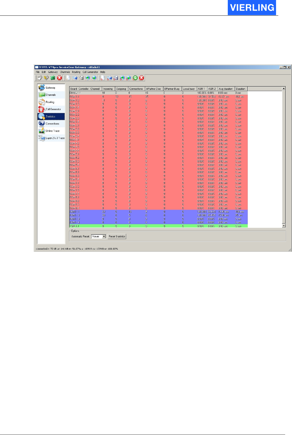
13. Statistics
The statistics view provides detailed information over the passed calls. The channel types
are colored different because of a better readability.
Attribute: Description:
Board-Controller-
Channel
Names the specific channel in the syntax
<Board>.<Controller>.<Channel>
Incoming Counts the total number of incoming calls
Outgoing Counts the total number of outgoing calls
Connections Counts the total number of connected calls
APartnerDisc Counts the number of calls that have been finished by the A-partner
BPartnerBusy Counts the number of calls that have been finished by the B-partner
Local Busy Counts the number of calls that could not been routed because of a
lack of GSM channels
ASR1 Average Seizure Ratio 1: Quotient between successful calls and all
calls whereas the calls that are abolished by the A-party before
connect are counted as successful calls.

ECOTEL® VTMpro 2005-06-08 Page 69
ASR2 Average Seizure Ratio 1: Quotient between successful calls and all
calls whereas the calls that are abolished by the A-party before
connect are counted as failed calls.
Example: 10 calls, 3 disc by network, 1 disc by A-party
ASR1= (10-3)/10*100=70%
ASR2=(10-4)/10*100=60%
Average duration Displays the average duration in seconds of the calls.
Duration Displays the over all minutes that have been terminated through this
port.
The statistic values can be reset automatically by setting the Automatic Reset parameter
from never to daily, weekly or monthly. The statistic can also be retted by pressing the
Reset Statistics button.
ECOTEL® VTMpro 2005-06-08 Page 70
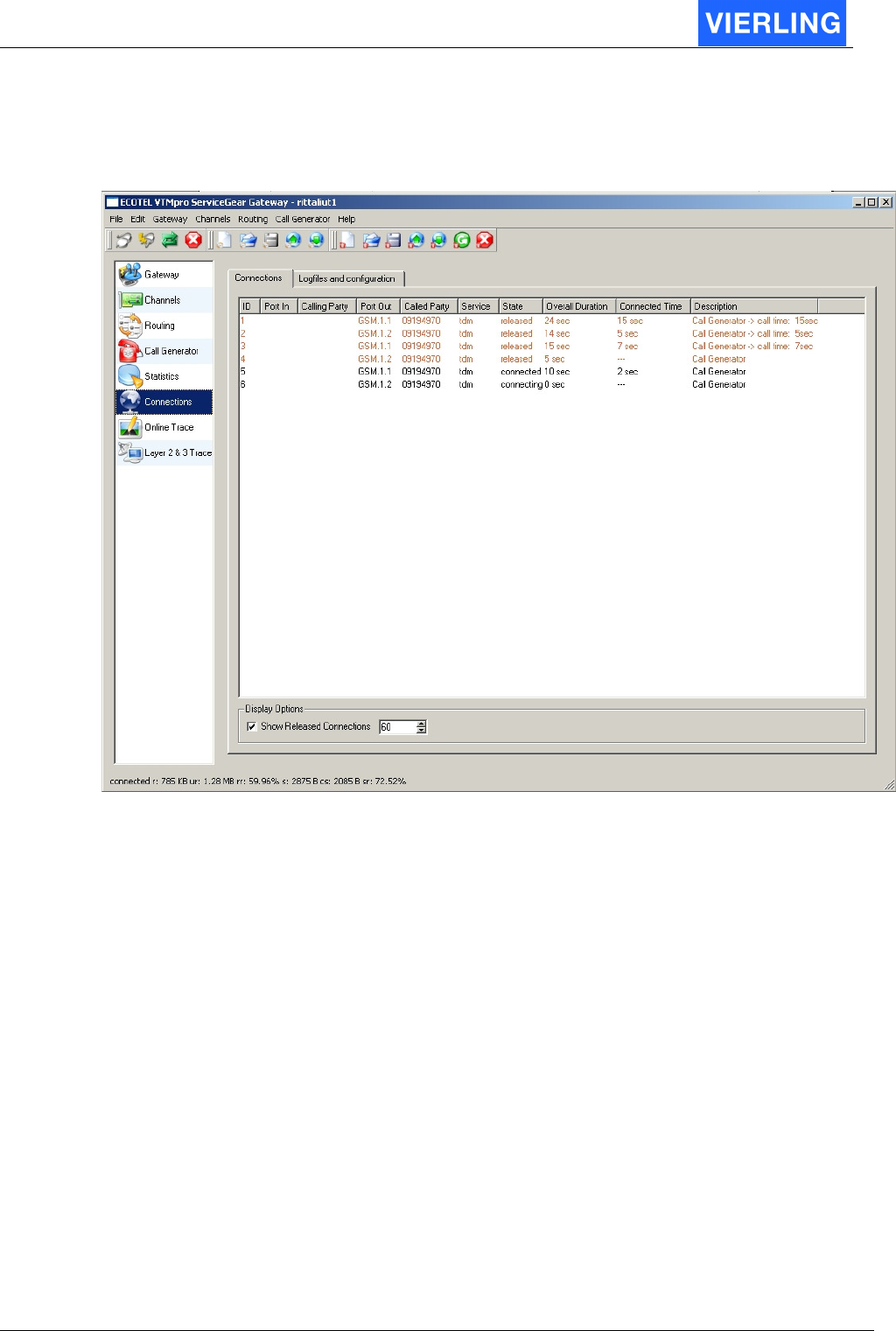
14. Connections
14.1
Connections view
The connection view provides online the current connection on the VTMpro. To ease the
monitoring of the flow the “Show Released Connections” box can be checked on. This
function provides the display of the released connections for the time in the box beside
set.
ECOTEL® VTMpro 2005-06-08 Page 71
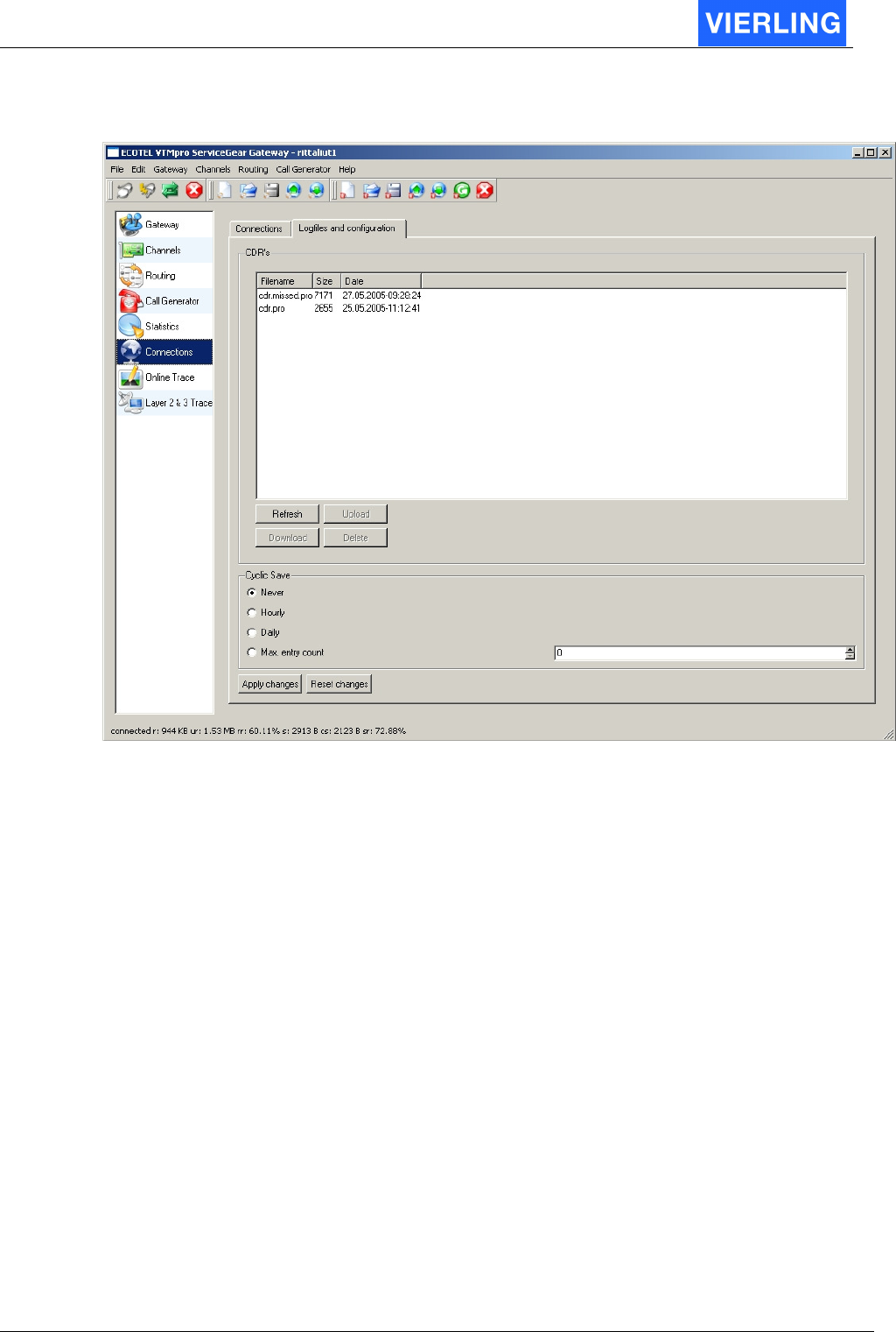
14.2
Logfiles and configuration
The “Logfiles and configuration” view provides the administration of call data records. The
call data records are separated in cdr.pro for successful calls and cdr_missed.pro for the
unsuccessful calls.
The files can be uploaded and downloaded between the ECOTEL
®
VTMpro and the local
machine. To refresh the display of the files, e.g. to monitor the files size the “Refresh”
button is provided. A selected file can be deleted by pressing the “Delete” button.
The files can also be cyclic saved and renamed. The period of doing this can be set by
time parameters or maximum contents of lines within the file.
The files are renamed from:
cdr.pro to cdr_<Year><Month><Day>_<Hour><Minute><Second>.pro
Example: When the file is renamed at 29. Mai 2005 at midday the file will be renamed to:
Cdr.pro > cdr_20050529_120000.pro
The default location the files will be downloaded to the local machine is:
C:\documents and settings\<username>\VTMpro_ServiceGear\<Gatewayname or IP
address>\..

ECOTEL® VTMpro 2005-06-08 Page 72
15. Online Trace
The Online Trace view contents enhanced trace functions that helps the VIERLING
technical support and developers retrieving internal problems. This tool is only used on
order of this two groups. The user trace functions consists of the following described
“Layer 2&3 Trace”
ECOTEL® VTMpro 2005-06-08 Page 73
16. Layer 2&3 Trace
The Layer 2&3 Trace provides sophisticated trace functions for retrieving especially GSM
and interconnection problems.
16.1
Offline trace and settings
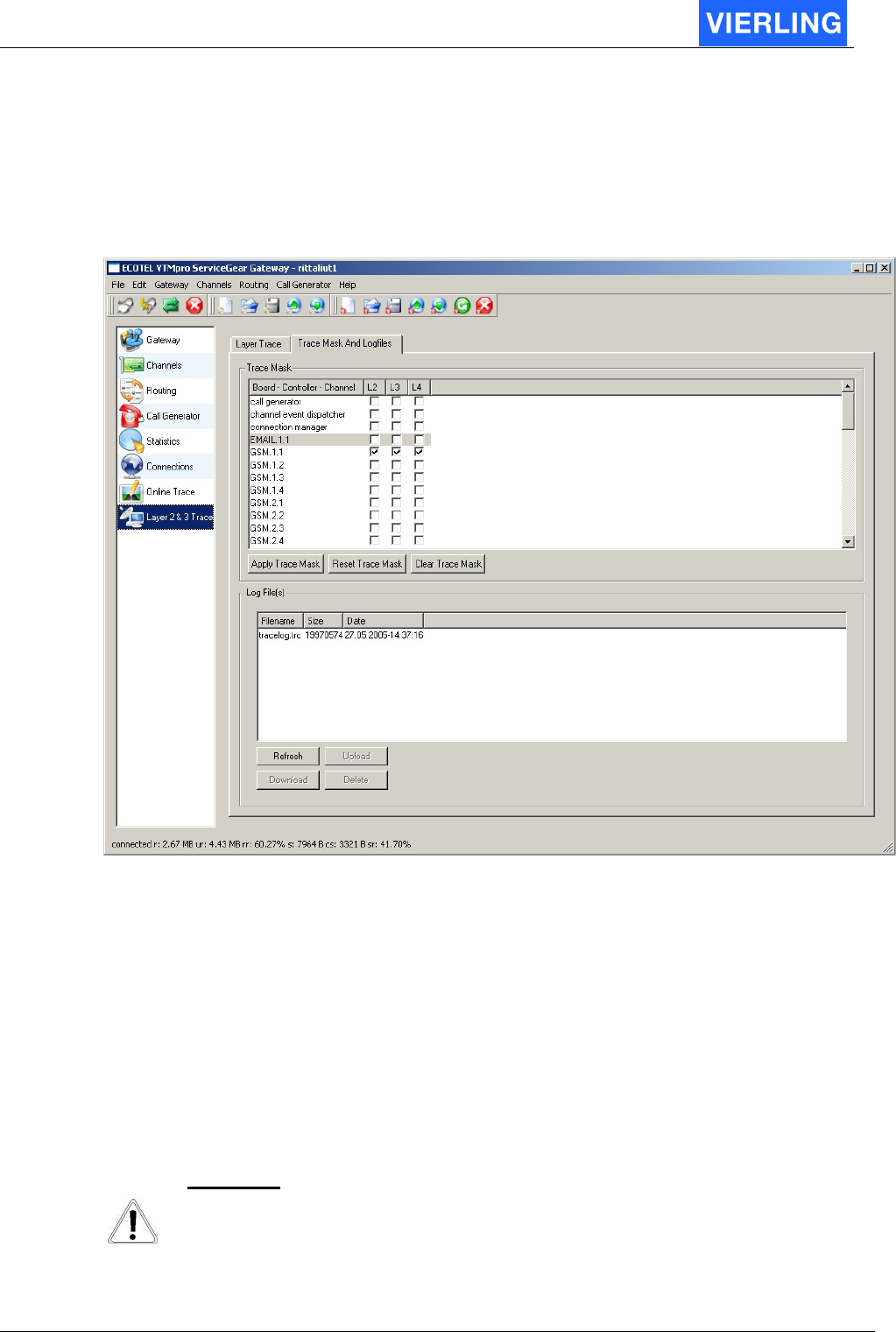
The trace options can be set very detailled by the “Trace Mask And Logfiles” panel.
16.1.1 Trace Mask
The Trace mask provides the option to switch traces on in a detailed depth. Every channel
has there levels of traces. L1 means very low level and detailed trace, L3 means higher
abstracter level traces. After setting a trace mask press “Apply Trace mask” to confirm the
settings.
For the GSM channels there is another settings for L1 trace configuration on boars level.
Therefore select: Channels -> GSM.<Board> -> GSM.<Board>.<Channel> ->
Layer2Trace
A
TTENTION
Traces always affects a system. Handle switching on traces very carefully. To
many traces can paralyze the system in case of too high load. Normally all
traces should be switched off.
ECOTEL® VTMpro 2005-06-08 Page 74
16.1.2 Offline Trace
There is always offline a tracefile logged name tracelog.trc. The depth of information
depends on the set trace mask. The files can be uploaded and downloaded between the
ECOTEL
®
VTMpro and the local machine. To refresh the display of the files, e.g. to
monitor the files size the “Refresh” button is provided. A selected file can be deleted by
pressing the “Delete” button.
A
TTENTION
To many switched on traces do not only affect the systems behavior in reaction
time and performance it will also create huge amounts of data waste that will fill
the harddisc space quite fast
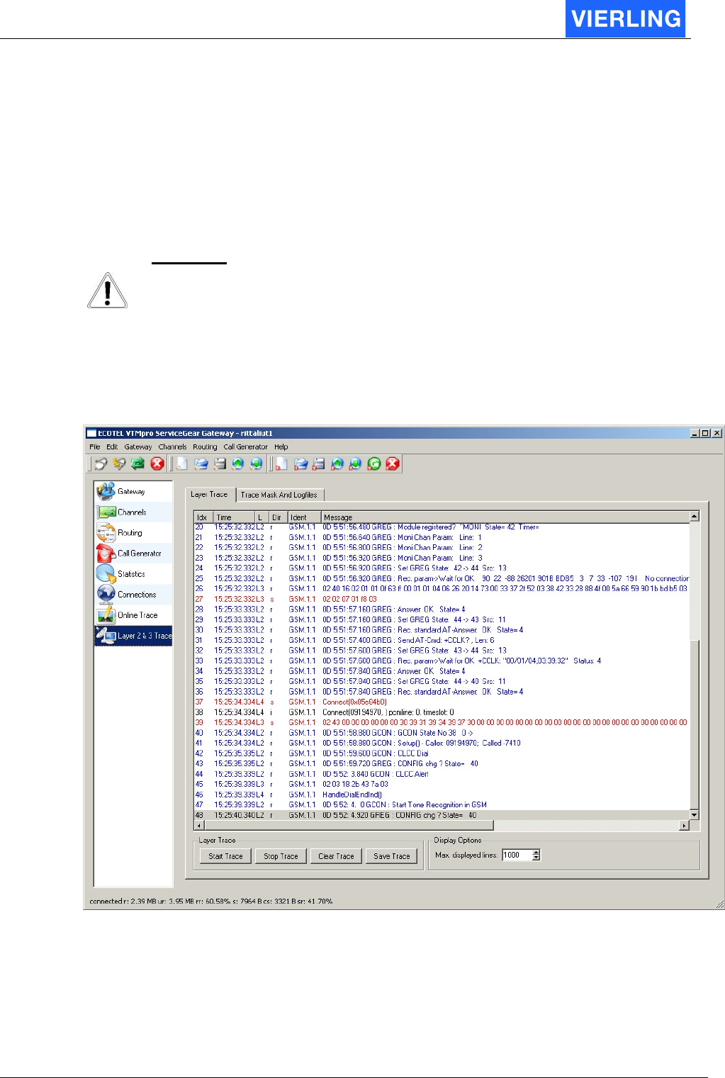
16.2
Online trace
For viewing traces online a “layer trace” window is provided:
To start a trace the “Start Trace” button from the layer trace must be pressed. To stop the
running trace the “Stop Trace” button must be pressed. The online trace can also be
saved by using the “Save Trace” button. The window is cleared by pressing the “Clear
Trace” button. The contents within the trace file is thereby not affected.
A limit can be set for the max displayed lines.

ECOTEL® VTMpro 2005-06-08 Page 75
17. CDR – Call Data Records
17.1
General
Every call causes a entry into a logfile. The successful calls are logged into cdr.pro, the
unsuccessful calls into cdr_missed.pro.
The files can be downloaded from the gateway to the local host for further working with.
The files are loaded down by following steps:
•
Logging into the gateway by using ServiceGearGateway.
•
Changing to the “Connections” view from the vertical icon bar.
•
Changing to the view “Logfiles and configuration”
•
Selecting a file from the CDR´s list box.
•
Pressing the “Download” button
•
Selecting a folder for the file or using the default folder.
•
Editing a name and press “Save”.
The CDR´s can be renamed automatically by selecting a mode from the “Cyclic Save”
menu. The file is therefore renamed at midnight to the name:
cdr_<Year><Month><Day>_<Hour><Minute><Second>.pro
The CDR files are located at the ECOTEL
®
VTMpro in the folder:
//vierling/var/cdr/..
17.2
Format
The CDR consists of strings separated by comma and terminated by carriage return at the
end of the line.
No.
String Description Example
1 Starttime Start time of the call 19.05.05-12:05:16
2 Endtime End time of the call 19.05.05-12:05:21
3 IncommingPort Is represented by a string. It can be numbers or
letters. It belongs to how the incoming port is be
named in the routing. The name is given in
:Routing->Port Properties->Name
10 (or ISDN)
4 A-party No. The CLI of the A-party 12345
5 Outgoing
Port
Is represented by a string. It can be numbers or
letters. It belongs to how the outgoing port is be
named in the routing. The name is given in
:Routing->Port Properties->Name
20 (or GSM)
6 B-party No. The CLI of the B-party 01733667123
7 IMSI The IMSI of the SIM card 262014730033372
8 IMEI The IMEI of the GSM module the call has been
terminated
520338416255177
9 Call Mode The Mode of the call :
0101 = ISDN
0101
10 Duration The length of the call in seconds 5
11 Billing Info Provides the billing information, that has been
sent. (Only in ISDN mode if selected)
0

ECOTEL® VTMpro 2005-06-08 Page 76
18. Tools
18.1
Secure Shell-Tool-PuTTY
On the ECOTEL
®
VTMpro CD there is provided the freeware programme PuTTY. This
programme enables to login to the ECOTEL
®
VTMpro by secure shell SSH. Because of
ECOTEL
®
VTMpro is based on LINUX there is the option to control the system on a deep
level.
A
TTENTION
Linux or Unix knowledge is severe recommended for using this tool!
18.2
Secure Copy-Tool-PSCP
To copy a file (e.g. a new ECOTEL
®
VTMpro software release) from a Windows system to
the LINUX based ECOTEL
®
VTMpro there can be used the freeware programme PSCP.
This tool is command line based and must be run in a command box. To copy a file from
Windows to ECOTEL
®
VTMpro the following steps must be done:
•
Locate the folder PSCP is locate on the windows system by using the dos box an
the commands cd <foldername>
•
Type into the dos box:
pscp c:\<foldername>\<filename> <username>@<VTMpro Name or IP address>
•
Default the username is “Vierling”
•
Then there is asked for a password. The default password is “neuneu”.
•
The file will be copied
A
TTENTION
Linux is very sensitive in permissions to file actions. To copy successfully there
must be provided, that the user name is used, owns the necessary permissions.