VIERLING Communications ECVTM-PRO Cellular Gateway System User Manual Manual ECOTEL VTMpro 1 1
VIERLING Communications GmbH Cellular Gateway System Manual ECOTEL VTMpro 1 1
Contents
- 1. Users Manual Part I
- 2. Users Manual Part II
- 3. Users Manual Part III
Users Manual Part II
ECOTEL
®
VTMpro
Manual
Issue 1.1
VIERLING Communications GmbH
70463.201/20 - 1.1 – 20050630

ECOTEL® VTMpro 2005-06-08 Page 2
Table of Contents
1.
Definition ...........................................................................................................5
2.
Quick Start.........................................................................................................6
2.1 Components....................................................................................................... 6
2.2 ECOTEL® VTMpro front view ............................................................................6
2.3 ECOTEL® VTMpro back view............................................................................7
2.4 Pinning of connectors......................................................................................... 7
2.4.1
Ethernet for LAN and VoIP .........................................................................7
2.4.2
E1/T1 .........................................................................................................8
2.5 Interpreting of board connectors and status LEDs..............................................9
2.5.1
Mainboard ..................................................................................................9
2.5.2
E1/T1 .........................................................................................................9
2.5.3
VoIP .........................................................................................................10
2.5.4
GSM-Card ................................................................................................10
2.6 Getting started ................................................................................................. 11
3.
Introduction......................................................................................................12
3.1
General ............................................................................................................ 12
3.2
Controlling the ECOTEL
®
VTMpro local and LINUX environment..................... 12
3.3
Controlling the ECOTEL
®
VTMpro from WINDOWS environment .................... 12
4.
Softwareinstallation .........................................................................................13
5.
ServiceGear – ECOTEL
®
VTMpro administration ............................................14
6.
Setup network interface...................................................................................16
6.1
Default Configuration .......................................................................................16
6.2
Changing network configuration....................................................................... 16
7.
Connect to Remote Gateway...........................................................................19
8.
ServiceGear - Gateway ...................................................................................20
8.1
Statusline ......................................................................................................... 20
8.1.1
File ...........................................................................................................20
8.1.2
Gateway ...................................................................................................20
8.1.3
Channels ..................................................................................................21
8.1.4
Routing.....................................................................................................21
8.1.5
Call Generator..........................................................................................21
8.1.6
Help..........................................................................................................21
8.2
Horizontal Icon Bar........................................................................................... 22
8.3
Vertical Icon Bar............................................................................................... 22
9.
Gateway ..........................................................................................................24
9.1
Gateway........................................................................................................... 24
9.2
Configuration.................................................................................................... 25
9.3
License ............................................................................................................ 25
10.
Channels .........................................................................................................26
10.1
Email................................................................................................................ 27
10.1.1
General ....................................................................................................27
10.1.2
Details ......................................................................................................27
10.1.3
Usage Step by step ..................................................................................28
10.2
VoIP................................................................................................................. 30
10.2.1
Information ...............................................................................................32
10.2.2
License Key..............................................................................................32
10.2.3
Board Configuration..................................................................................32
10.2.4
VoIP Configuration ...................................................................................33
10.2.5
Firmware ..................................................................................................33

ECOTEL® VTMpro 2005-06-08 Page 3
10.3
GSM................................................................................................................. 33
10.3.1
Board Control Panel .................................................................................33
10.3.2
Channel Control Panel .............................................................................37
10.4
ISDN ................................................................................................................ 43
10.4.1
Information ...............................................................................................43
10.4.2
Configuration............................................................................................44
10.5
Simcontrol........................................................................................................ 45
10.5.1
Overview ..................................................................................................45
10.5.2
Functions in detail ....................................................................................45
10.6
SMC Sim Management Center......................................................................... 46
10.6.1
General ....................................................................................................46
10.6.2
Local SIMs ...............................................................................................47
10.6.3
SIM Groups ..............................................................................................50
11.
Routing............................................................................................................53
11.1
Establishing a new routing step by step ........................................................... 53
11.2
Routing features in detail.................................................................................. 54
11.2.1
Philosophy................................................................................................54
11.2.2
Routings...................................................................................................54
11.2.3
Port Routing List.......................................................................................55
12.
Call Generator .................................................................................................65
12.1
Overview.......................................................................................................... 65
12.2
Functions in details .......................................................................................... 67
12.2.1
Horizontal Icon bar ...................................................................................67
12.2.2
Elements from main view..........................................................................67
13.
Statistics..........................................................................................................68
14.
Connections ....................................................................................................70
14.1
Connections view............................................................................................. 70
14.2
Logfiles and configuration ................................................................................ 71
15.
Online Trace....................................................................................................72
16.
Layer 2&3 Trace..............................................................................................73
16.1
Offline trace and settings.................................................................................. 73
16.1.1
Trace Mask ..............................................................................................73
16.1.2
Offline Trace.............................................................................................74
16.2
Online trace...................................................................................................... 74
17.
CDR – Call Data Records................................................................................75
17.1
General ............................................................................................................ 75
17.2
Format ............................................................................................................. 75
18.
Tools ...............................................................................................................76
18.1
Secure Shell-Tool-PuTTY ................................................................................76
18.2
Secure Copy-Tool-PSCP .................................................................................76

ECOTEL® VTMpro 2005-06-08 Page 4

ECOTEL® VTMpro 2005-06-08 Page 5
1. Definition
ECOTEL
®
VTMpro is a multichannel gateway from the VIERLING gateway family that
provides the connection between fixed and mobile network of up to 32 channels. It
supports 4 ports with 30 channels ISDN PRI E1/T1, 4 ports with 2 channels ISDN 4xBRI
E1/T1, 1 Port/30 channels VoIP/H.323 interface at the fixed and up to 32 channels GSM
850/1900 and/or GSM 900//1800 MHz at the mobile network interface. The ECOTEL
®
VTMpro has a sophisticated routing software that can be controlled local or remote by a
graphical user interface. The gateway provides furthermore versatile statistics, trace and
monitorfunctions. Call data files for billing can also be created and saved.
ECOTEL® VTMpro 2005-06-08 Page 6
2. Quick Start
2.1
Components
ECOTEL
®
VTMpro is optionally equipped with different boards. The boards can be
accessed by the back of the housing. The available boards are (detailed description later
in the manual):
•
Mainboard
•
VoIP card
•
ISDN PRI card
•
ISDN BRI card
•
GSM card
•
Antenna splitter card
The mainboard is mandatory all other boards are optionally. Normally ECOTEL
®
VTMpro
is equipped with one of the boards VoIP, ISDN PRI or ISDN BRI and one to eight GSM
cards.
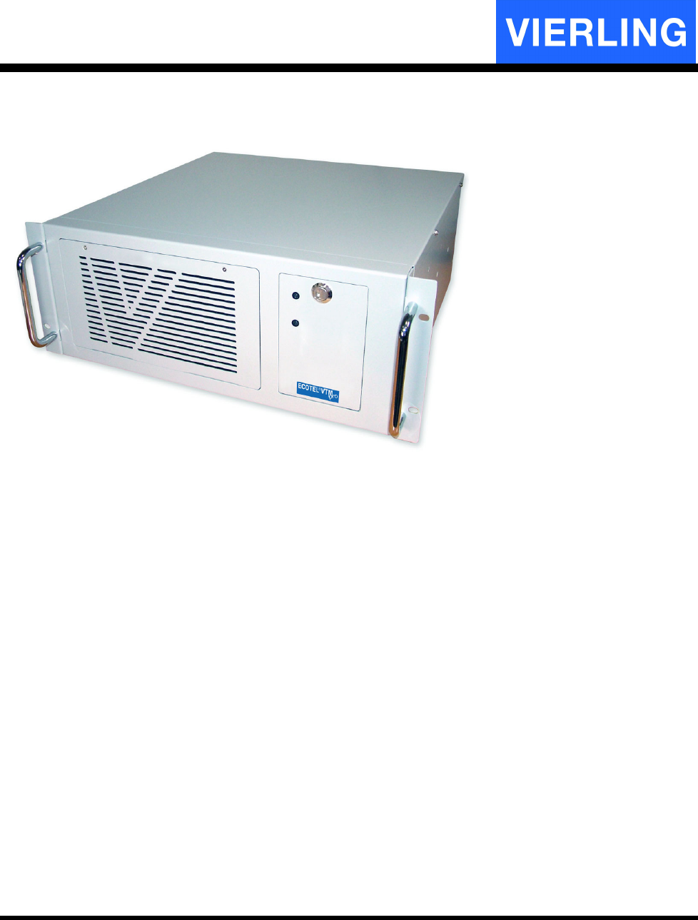
2.2
ECOTEL
®
VTMpro front view
Fix point for
rack mounting
VTMpro front:
Grip for
carrying
Cover for
air filter
Switch
Floppy
LED HarddiscLED Power
Lock
Screw for removing air filter
ECOTEL® VTMpro 2005-06-08 Page 7
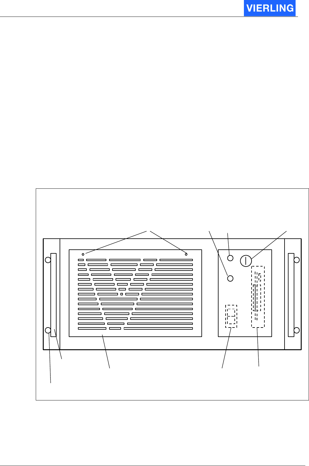
2.3
ECOTEL
®
VTMpro back view
Power
supply
Power for
monitor
Main
switch
ISDN
4xE1/T1
1
2
3
4
VoIP
Mainboard
Keyboard/Mouse
(via adapter)
GSM-Card
1
2
3
4
5
6
7
8
Antenna
GSM
2 to 8
GSM
1 to 4
VTMpro back view:
Monitor
LAN
(for remote access)
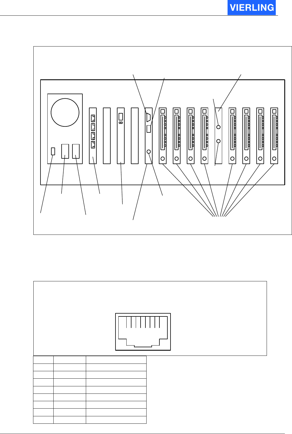
2.4
Pinning of connectors
2.4.1 Ethernet for LAN and VoIP
Ethernet LAN and VoIP port (RJ
-
45 socket):
1 2 3 4 5 6 7 8
Pin Signal Description
1 TX + Transmit Data
2 TX - Transmit Data
3 RX + Receive Data
4 Res Reserved
5 Res Reserved
6 RX - Receive Data
7 Res Reserved
8 Res Reserved
ECOTEL® VTMpro 2005-06-08 Page 8
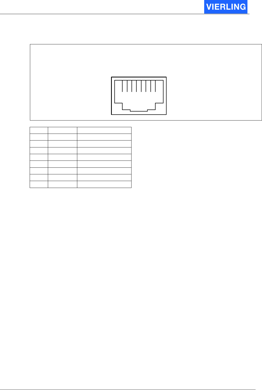
2.4.2 E1/T1
Ethernet LAN and VoIP port (RJ-45 socket):
1 2 3 4 5 6 7 8
Pin Signal Description
1 RX + Receive Data
2 RX - Receive Data
3 Res Reserved
4 TX+ Transmit Data
5 TX- Transmit Data
6 Res Reserved
7 Res Reserved
8 Res Reserved
ECOTEL® VTMpro 2005-06-08 Page 9
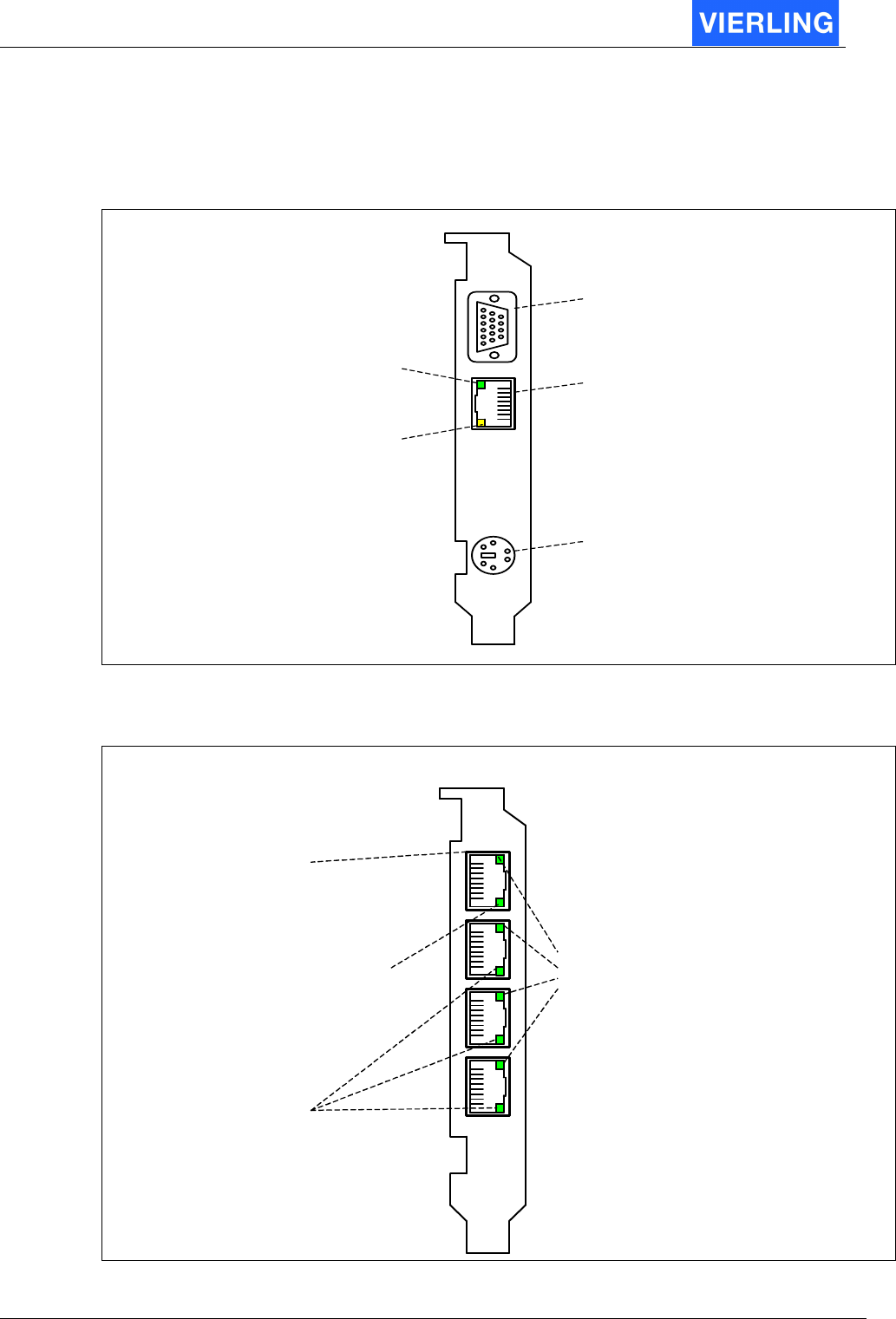
2.5
Interpreting of board connectors and status LEDs
2.5.1 Mainboard
M ainB oard:
Receive Data (yellow )
Lights when data is
received
LAN
RJ45 socket
Link (green)
Lights when ethernet
connection is on
Monitor
PS/2 Console
Keyboard/Mouse
via adapter
2.5.2 E1/T1
E1/T1:
L1 Status LED
Off: L1 not active
On: L1 active
Status for each port
Firmware Status LED
• Flashing fast (1Hz):
Firmware not running
• Flashing slow (1/2 Hz):
Firmware running
Status for all ports
No meaning!
RJ45 socket
1
2
3
4
ECOTEL® VTMpro 2005-06-08 Page 10
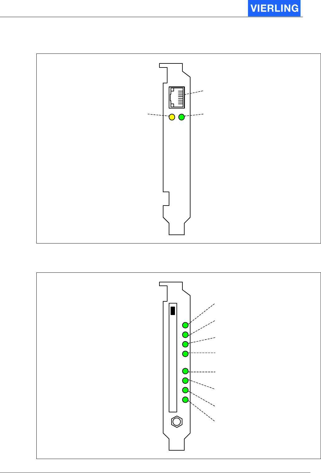
2.5.3 VoIP
VoIP:
Receive Data (yellow)
Lights when data is
received
RJ45 socket
Link (green)
Lights when ethernet
connection is on
2.5.4 GSM-Card
GSM-Card:
SIM:
Flashing: Registering in progress
On: Registered
1
2
3
4
1
2
3
4
GSM:
Flashing: Call establishing
On: Call active
Ch 1
Ch 2
Ch 3
Ch 4
Ch 1
Ch 2
Ch 3
Ch 4
Ant
S
I
M
G
S
M

ECOTEL® VTMpro 2005-06-08 Page 11
2.6
Getting started
To get the ECOTEL
®
VTMpro started follow this instruction:
•
Remove VTMpro from the box
•
Plug in the power cable shipped with
•
Connect the power cable with power supply: 110-240 Volt/50-60 Hz
•
Plug in the adapter for keyboard and mouse.
•
Connect a keyboard, mouse and monitor to the adapter. The console can be
removed after very basic settings.
•
Optionally plug in the ethernet cable in to the RJ45 socket of the main board to
control the ECOTEL
®
VTMpro by remote
•
Optionally connect the VoIP card with the LAN
•
Optionally connect one or more sockets of the E1/T1 card to a switch/pbx or
router.
•
Connect an antenna to the “Antenna” slot
•
Assemble the SIM carrier within the GSM cards with SIMs
•
Switch on the main switch at the power supply
•
Press the switch below the front cover
•
The ECOTEL
®
VTMpro will start up
•
Follow the instructions in the “ECOTEL
®
VTMpro Software part
•
To switch off press the button under the front cover for at least 5 seconds, or shut
it down over the “Start” menu via terminal.

ECOTEL® VTMpro 2005-06-08 Page 12
3. Introduction
3.1
General
ECOTEL
®
VTMpro is a LINUX based gateway for interconnection between fixed and
mobile network. The embedded controlling intelligence runs without a face within the
LINUX system. The controlling intelligence further in context, also called as gateway,
routing engine or LCR, has a network interface for remote controlling. There is a GUI
available using this interface. The GUI has two compilations: One for LINUX and one for
WINDOWS. The LINUX version is also installed on the ECOTEL
®
VTMpro and can be
started there to control the local gateway or the gateway from a different ECOTEL
®
VTMpro within the network.
3.2
Controlling the ECOTEL
®
VTMpro local and LINUX environment
To start the ServiceGear on local ECOTEL
®
VTMpro follow the instruction:
1. Connect a console (Monitor, Keyboard Mouse) to the gateway. For connecting the
keyboard and mouse the delivered adapter must be used
2. After the boot sequence login with following default parameters:
User: vierling
Password: vierling
3. A gear-wheel icon “ECOTEL
®
VTMpro ServiceGear” appears on the desktop.
Click ion this symbol to start the maintenance GUI.
4. Choose the gateway symbol from the vertical icon bar and press connect. By
default the local machine can be accessed by the name “localhost”, no password
is given.
A
TTENTION
For security reason the password should be changed.
5. To connect to the local gateway press the “Connect” button.
3.3
Controlling the ECOTEL
®
VTMpro from WINDOWS environment
To control the ECOTEL
®
VTMpro from WINDOW the specific software must be installed,
which is explained in next chapter.

ECOTEL® VTMpro 2005-06-08 Page 13
4. Softwareinstallation
Start the self inflating installing routine by double clicking on the following symbol from the
CD:
After the start follow the instructions!
The ServiceGear needs .Net framework from Microsoft. This framework is already
installed on newer Windows installations. If not the ECOTEL
®
VTMpro installer will cancel
the installation and advice to install the framework first. It gives also the option to do this
immediately by providing this installation also by the ECOTEL
®
VTMpro installer. After the
framework installation the ECOTEL
®
VTMpro ServiceGear installation can be started
again.
ECOTEL® VTMpro 2005-06-08 Page 14
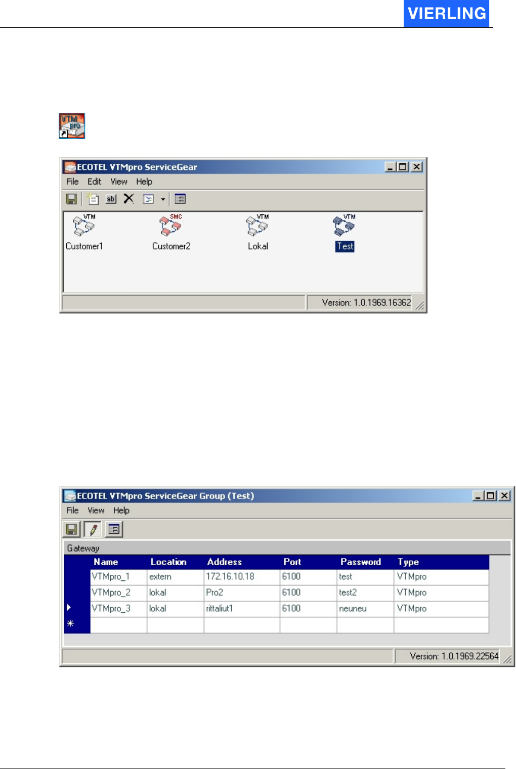
5. ServiceGear – ECOTEL® VTMpro administration
After the successful installation the ECOTEL
®
VTMpro ServiceGear can be started by
pressing the following icon on the desktop:
The administration area on group level appears.
The ServiceGear provides the possibility to administrate groups of ECOTEL
®
VTMpro e.g.
one group for each customer. (The screen shot shows already established groups).
To establish a new group the following steps must be done:
•
Select Edit->New Group or the empty sheet symbol.
•
Enter a group name at the field “Group Name”.
•
The other settings are for use of an external Sim Server und must not be changed.
•
Create the new group by pressing O.K..
The group can now bear many ECOTEL
®
VTMpro links. To apply a new ECOTEL
®
VTMpro to the new group double click on the specific group symbol within the ECOTEL
®
VTMpro Service Gear. The following Service Gear Group window appears:

ECOTEL® VTMpro 2005-06-08 Page 15
To enter a new ECOTEL
®
VTMpro the following steps must be done:
•
Click into a new line
•
Press the “Pencil” symbol button from the menu to leave read only modus. Enter
the following settings:
Attribut: Description:
Name: The ECOTEL
®
VTMpro can be given a individual name
Location The ECOTEL
®
VTMpro can be given an arbitrary optional label for the
physical location of the gateway.
Address The address must be mandatory given in form of a known name within
a network or a IP address.
Port The port the ServiceGear communicates with VTMpro. May normally
not be changed.
Password
Enter a valid password for the specific VTMpro. The default password
is: NeuNeu
Type Changes optionally the type of the Gateway and the ServiceGear to
start, because the administration is universal usable for other gateway
types.
•
Confirm the settings by pressing the “Pencil” symbol again
•
Select the ECOTEL
®
VTMpro to administrate the list and press the “GUI” symbol
beside the pencil to start ServiceGear for the VTMpro. The remote maintenance
will start with the correct items. Alternatively the ServiceGear gateway can be
started manually and the necessary address and password can be entered by
hand. See the following chapter:
ECOTEL® VTMpro 2005-06-08 Page 16
6. Setup network interface
ECOTEL
®
VTMpro can be administrated by remote via TCP/IP connection. Therefore
ECOTEL
®
VTMpro and the remote ServiceGear must be setup properly.
6.1
Default Configuration
The delivered default configuration of the network interface is setup to a static IP address,
as follows:
172.16.8.16
To reach the ECOTEL
®
VTMpro with the remote gear there are two possibilities of setup:
1. Set the ECOTEL
®
VTMpro IP configuration as default and configure the remote
desktop to the value. This can be done anyway by a local connection between
ECOTEL
®
VTMpro and the remote host by using a cross connect LAN cable.
Otherwise the ECOTEL
®
VTMpro must be integrated into a existing network with
this static IP address. For security reason it is recommended to ask your network
administrator!
2. Change the IP interface of ECOTEL
®
VTMpro to DHCP or to a static IP address
given by your network administrator. To change the IP interface the steps in the
following chapter must be done!
6.2
Changing network configuration
1. Start the ECOTEL
®
VTMpro and wait until the login screen appears
2. Login with the following parameters:
Login: vierling
Password: U2xK3te8
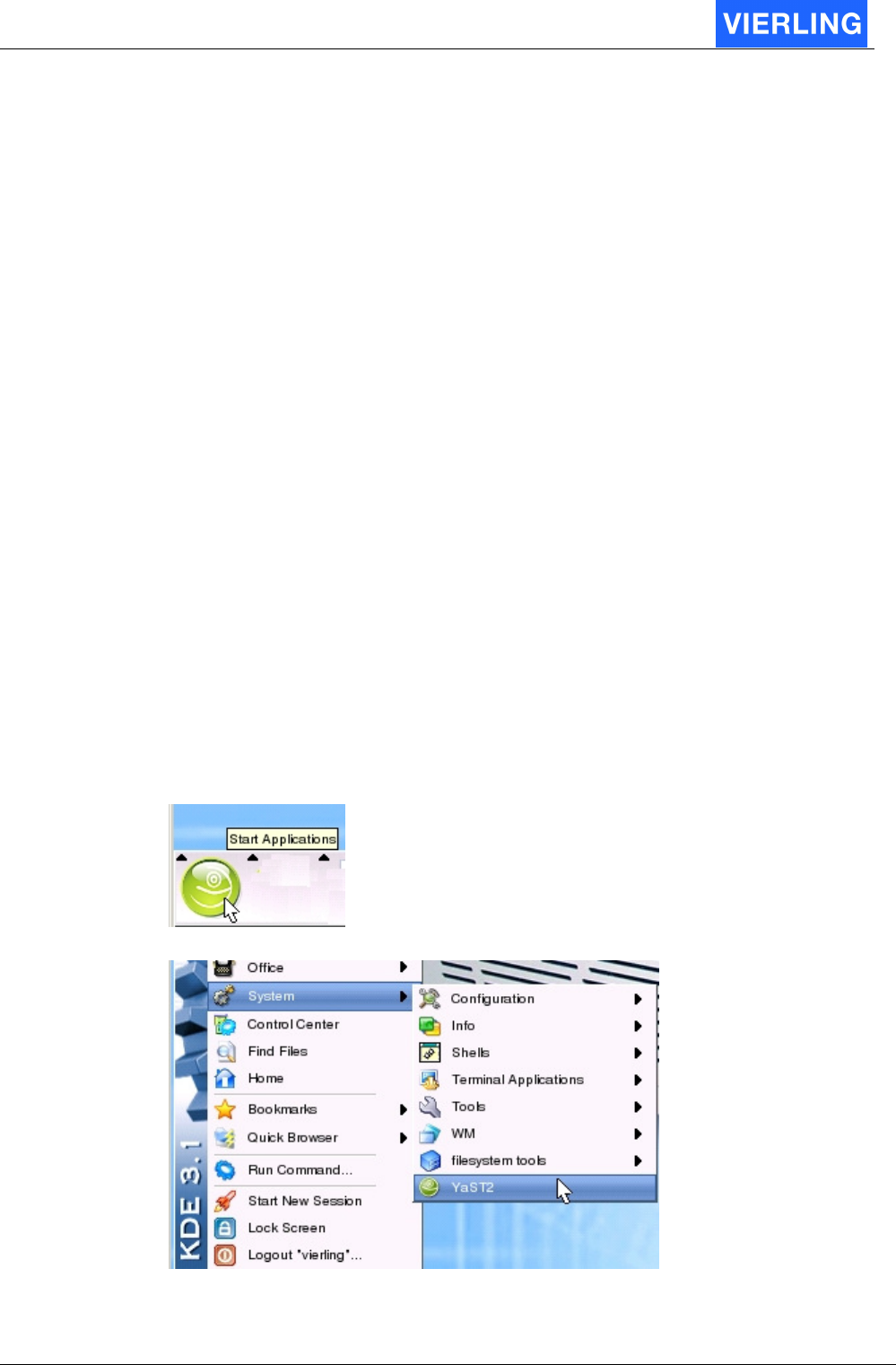
3. Wait until the desktop is loaded completely
4. Click on the “Start Applications” button in the left bottom corner
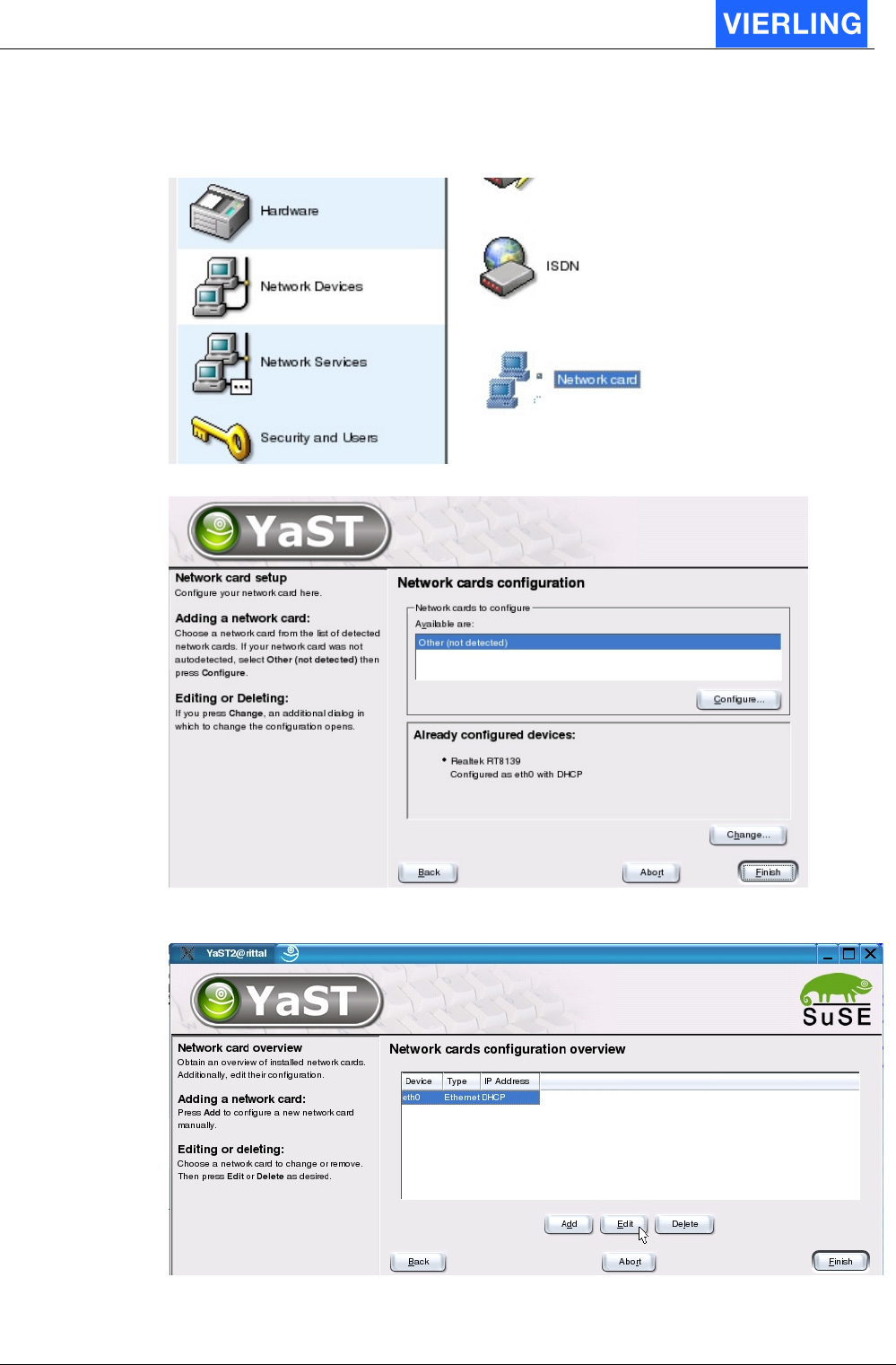
5. Chose from the appearing menu the System -> YaST2 configuration tool:
6. To make changes on system infrastructure the root password must be entered:
Password: gR76aLaB
ECOTEL® VTMpro 2005-06-08 Page 17
Confirm with OK.
Hint: Enter the password
7. Choose Network Devices ->Network card from the appearing menu:
8. Choose “Change...” in the right bottom corner:
9. Make sure that the “eth0” device is selected and press “Edit” button in the middle
ECOTEL® VTMpro 2005-06-08 Page 18
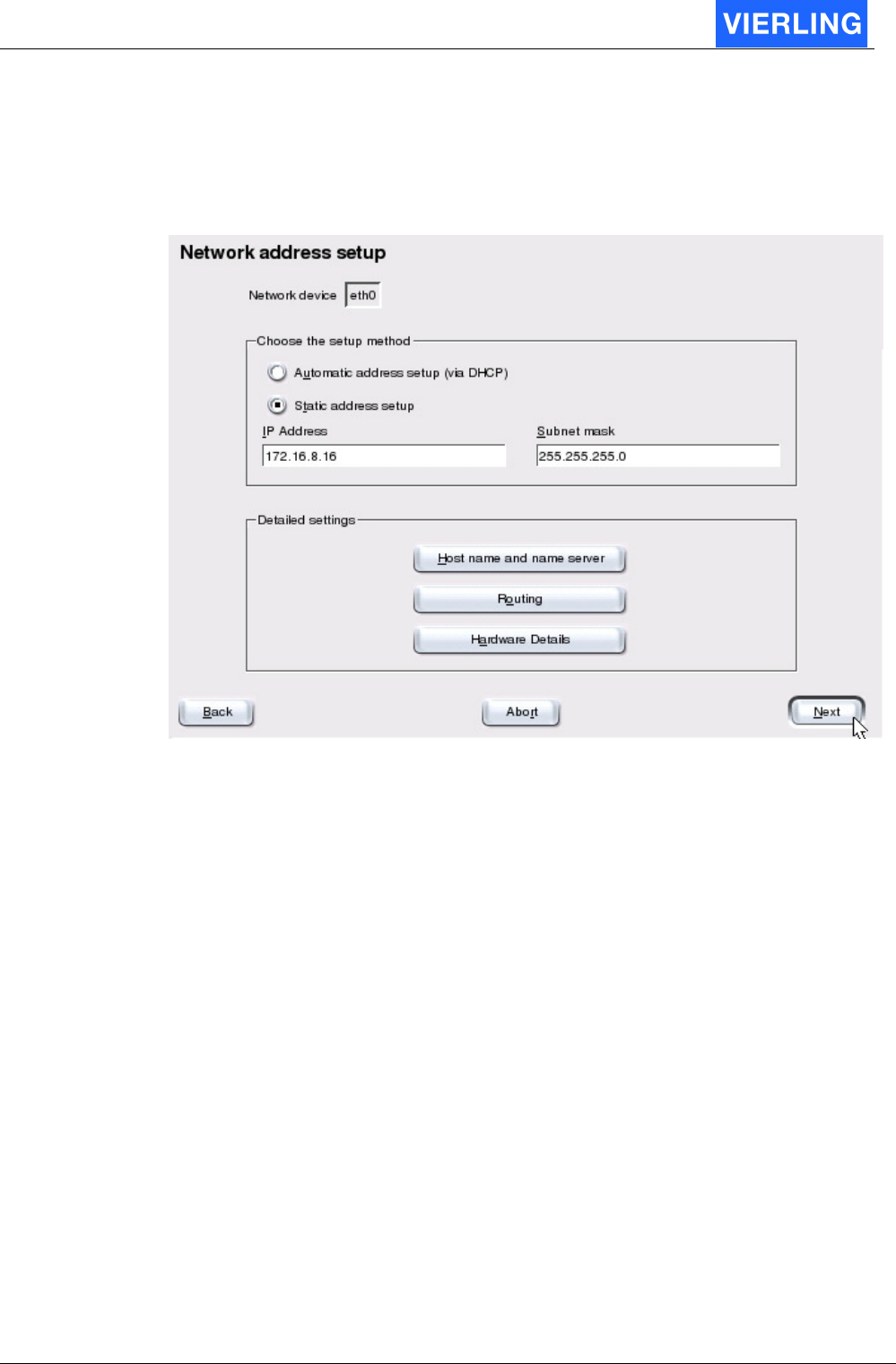
10. Select
- Automatic address setup (via DHCP) if there is a DHCP server available in the
network to get a dynamic IP address assigned to the ECOTEL
®
VTMpro name.
The ECOTEL
®
VTMpro default name is: rittal
- Or Static address setup for selecting or changing the default IP address.
Configure also the Subnet mask according to your network administrator.
Click on the “Next” button to confirm the settings
11. Finish the network configuration by pressing “Finish” at the screenshot from item 9
to close the settings.
12. Close the Yast control center by pressing “close”
13. Now ECOTEL
®
VTMpro settings are valid and it is reachable with the new
address.
ECOTEL® VTMpro 2005-06-08 Page 19
7. Connect to Remote Gateway
To connect the ECOTEL
®
VTMpro choose from the left row the item “Gateway” and enter
the individual IP address into the field “Host” on the appearing fields. The predefined port
in the field “Port” normally has not to be changed. When you have entered the correct IP
address and pressed the button “Connect” you will be connected to the VTMpro. The
connection is confirmed by the status line in the left bottom corner of the window. If there
is a connection established the status is “connected” otherwise it is “idle” (compare to the
next picture). By the way you can observe the amount of data transferred between the
application on the ECOTEL
®
VTMpro and the computer the ServiceGear is hosted.
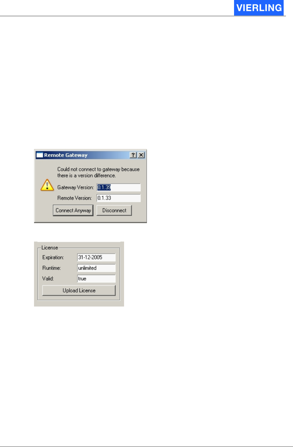
If the following screen appears you get a hint that you use different versions between the
application on the ECOTEL
®
VTMpro and the ServiceGear on your host. A version
conflict can happen, but normally the ServiceGear should be compatible until a certain
degree to former ECOTEL
®
VTMpro applications. You can connect by pressing the
“Connect Anyway” button.
After a successful connection the following part of the right screen part now carries valid
data:
This box shows license information. The ECOTEL
®
VTMpro may be restricted to a limited
lifetime. If lifetime has expired ECOTEL
®
VTMpro can not be further used. The “Valid”
field shows if ECOTEL
®
VTMpro can be still used or not. In case of expiration you can
load a valid license file to the system by using the function “Upload License”. Contact
VIERLING Communications support how to get such a license file. The lifetime is
separated in two categories:
•
Expiration: The ECOTEL
®
VTMpro runs unlimited until this date. After this date the
ECOTEL
®
VTMpro is unusable.
•
Runtime: The ECOTEL
®
VTMpro runs as long as the amount of entered hours in
the dedicated field. After expiration the ECOTEL
®
VTMpro is unusable. Only the
active time is counted. The idle time is ignored.
ECOTEL® VTMpro 2005-06-08 Page 20
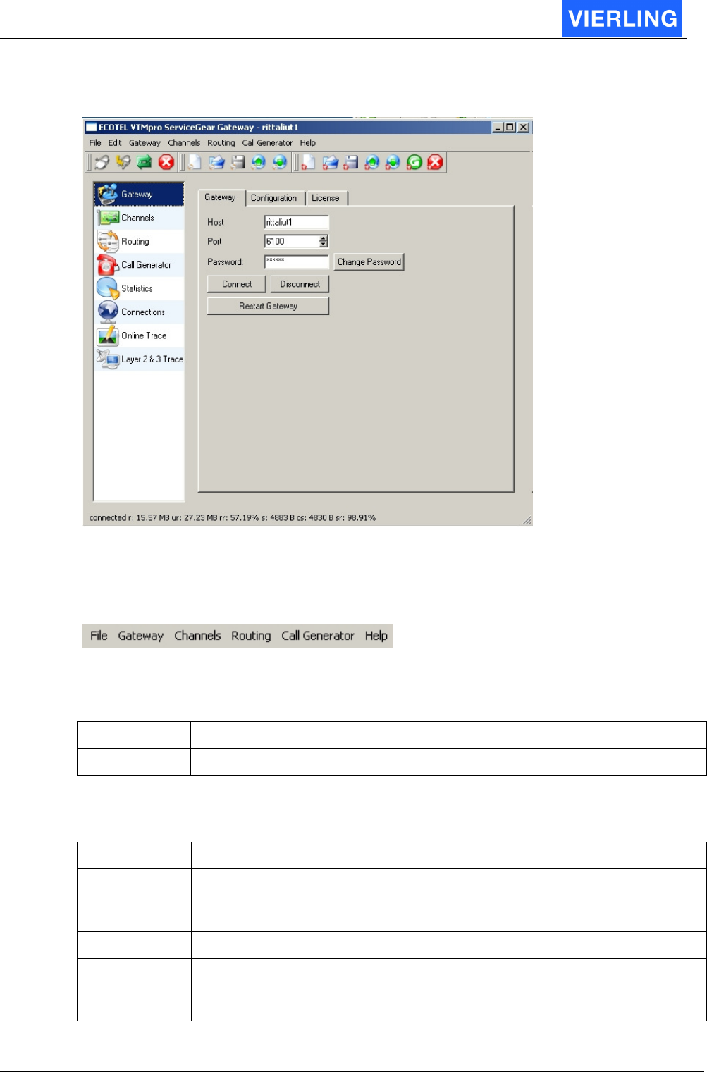
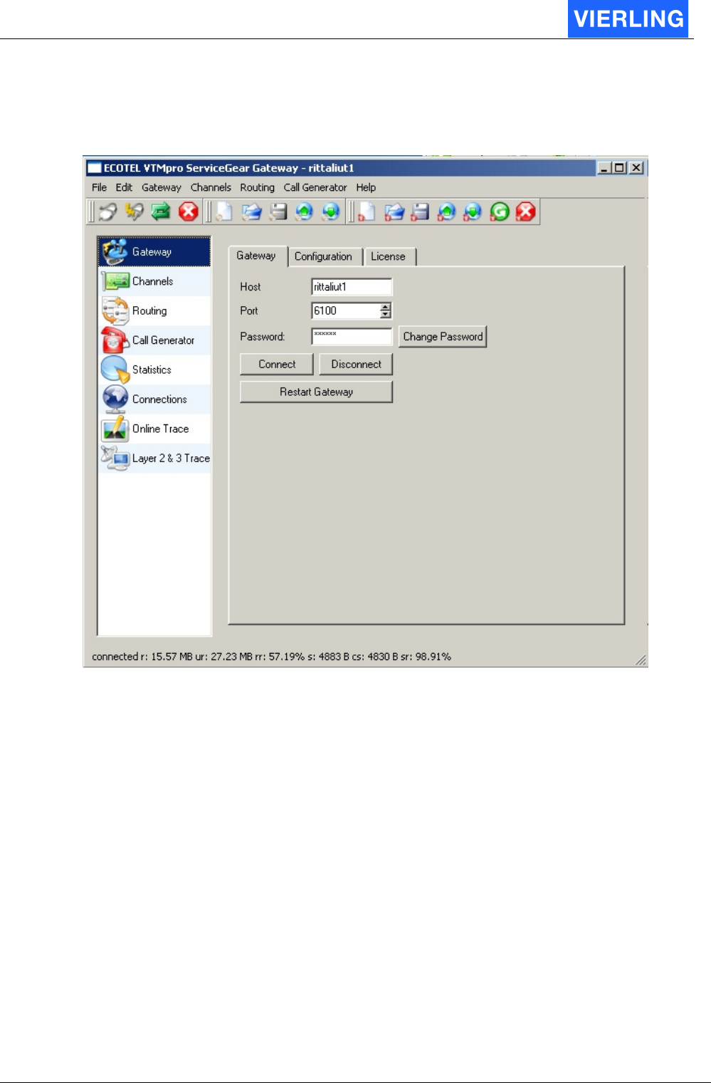
8. ServiceGear - Gateway
After starting the program “ECOTEL
®
VTMpro ServiceGear Gateway” you will see the
above screen. The screen contains different parts, explained as follows:
8.1
Statusline
The statusline contains different menu items:
8.1.1 File
Attribut: Description:
Quit: Closes ECOTEL
®
VTMpro ServiceGear Gateway
8.1.2 Gateway
Attribut: Description:
Connect: Connects to remote gateway. Same function like the button on the
appearing screen after choosing the “Gateway” item from the vertical icon
bar.
Disconnect: Closes a connection between the ServiceGear and the gateway.
Restart: Restarts the application on the gateway. The connection to the
ServiceGear closes automatically. A new connection is possible when the
application on the ECOTEL
®
VTMpro has rebootet.
ECOTEL® VTMpro 2005-06-08 Page 21
8.1.3 Channels
Attribut: Description:
Download
Configuration:
Retrieves a saved hardware configuration from the ECOTEL
®
VTMpro into the ServiceGear for manipulation or just for viewing.
Load and activate
configuration:
Loads a new established or loaded and manipulated hardware
configuration in to the remote VTMpro. The changes are only valid if
this has been done. Otherwise changes will be discarded.
This feature is useful to clone ECOTEL
®
VTMpro hardware settings.
8.1.4 Routing
Attribut: Description:
New Establishes a new routing configuration
Open Opens an already established and saved routing file from the local
machine
Save / Save as Saves a routing configuration on the local machine
Activate Activates a change in the routing on the VTMpro
Download Retrieves a routing from the ECOTEL
®
VTMpro in to the
ServiceGear
8.1.5 Call Generator
The call generator is a very useful tool for generating calls from any port of the ECOTEL
®
VTMpro for test aims.
Attribut: Description:
New Establishes a new configuration for the call generator.
Open Opens a configuration that is saved on the local machine
Save / Save as Saves a routing configuration on the local machine
Activate Activates a change in the configuration from the call generator in the
VTMpro
Download Retrieves a call generator configuration from the ECOTEL
®
VTMpro
to the ServiceGear.
Start Starts call procedure programmed in a call generator configuration
file
Stop Stops call procedure
8.1.6 Help
About: Information about the version of the ServiceGear
ECOTEL® VTMpro 2005-06-08 Page 22
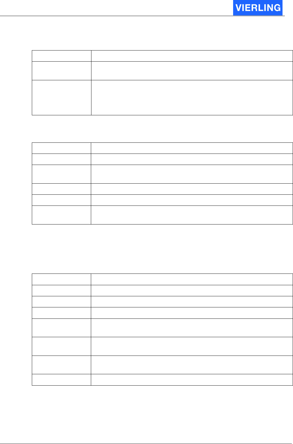
8.2
Horizontal Icon Bar
The horizontal icon bar is divided into three themes: Gateway, Routing and Callgenerator
Gateway Routing Callgenerator
The contents are the same like the menu described in the chapter before. To get
information about the meaning of the icons use the hover help function. If you hover the
mouse arrow over an item and you stay a little time on the same place then a box will be
shown with a short description of the dedicated button like the example above.
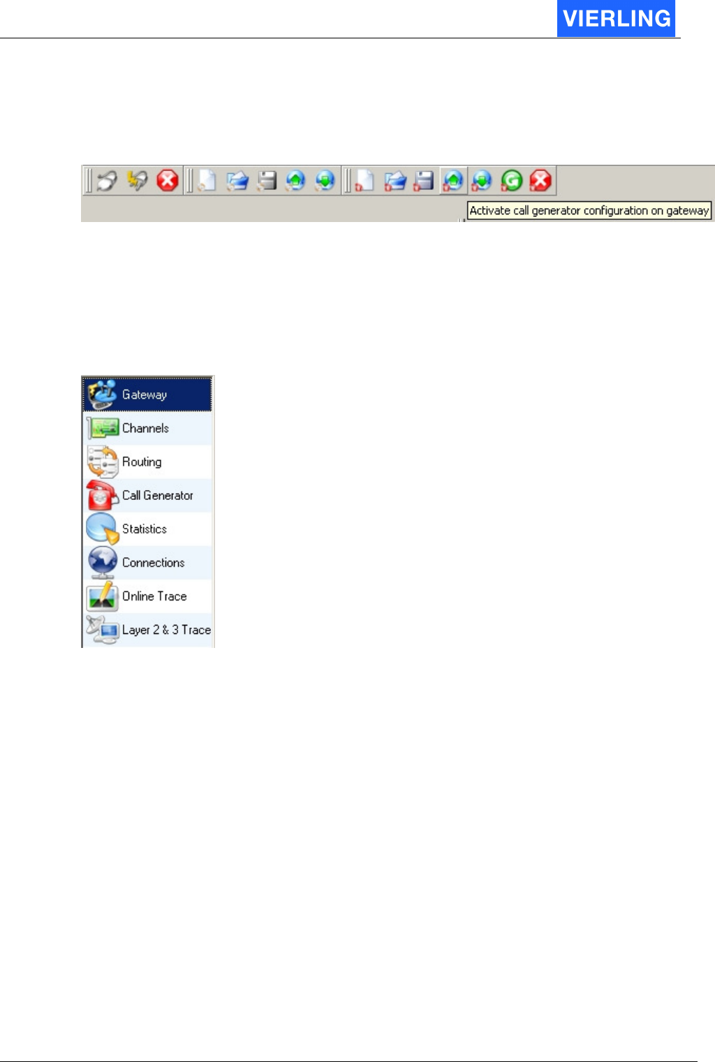
8.3
Vertical Icon Bar
The right side of the window depends on the choice from the vertical icon bar.
Gateway: Provides the function to enter the IP address, port number and control the
connection to the VTMpro. Furthermore there is a part to administrate license context.
View expiration values and validate new license files.
Channels: The main function of this menu item is to provide an overview of all
communication channels. These are basically all hardware ports to the environment, like
GSM-, ISDN- and VOIP-cards. Moreover this includes also system functions like SMS-
Email conversion, local SIM administration and SIM switching. Selecting one of the items
in the visible tree provides further information and settings about the dedicated channel.
Routing: Provides a window where the very flexible central routing functions can be
established. The routing is port organized. Every port has specific features and, except
from the premier and the last port, a predecessor and a successor.
Call Generator: This feature provides very useful test functions. One or more call
scenarios can be established and started to test own hardware ports, routing or other
devices working with VTMpro.
Statistics: Includes all function necessary to monitor a working system. It is possible to
view the statistic online organized in a column for every port. With these parameters the
maintain stuff can monitor if a systems runs well or not.
Connections: This view enables online monitoring. Each connection occupies one line.
The lines can be vanished with a configurable delay, the monitoring is very easy.

ECOTEL® VTMpro 2005-06-08 Page 23
Online Trace: Provides debug information for developing aims. This is interesting a
suspicion of a fault in the software arouses.
Layer2&3 Trace: Very powerful function to trace all ports as well hardware as system
ports like Email-SMS conversion. The trace can be scalably switched on or off and
provides different depth.
ECOTEL® VTMpro 2005-06-08 Page 24
9. Gateway
9.1
Gateway
Attribute Description
Host The name within a network with DHCP or the IP address of the
ECOTEL
®
VTMpro to control must be entered here
Port The port the ServicegearGearGateway communicates with the
ECOTEL
®
VTMpro can be changed here. Normally the default
values should not be changed.
Password The password for remote configuration must be entered here. The
password is key sensitive!
Change Password The actual password can be changed by pressing this button.
Connect/Disconnect
When all necessary data are entered the remote ECOTEL
®
VTMpro
can be connected by pressing this button. To confirm the
established connection the status line at the bottom must show
“connected”. To release the connection “Disconnect” must be
pressed.
Restart Gateway This button restarts the software of VTMpro.
ECOTEL® VTMpro 2005-06-08 Page 25
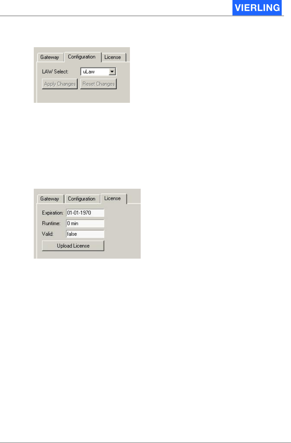
9.2
Configuration
Attribute Description
Law Select The ECOTEL
®
VTMpro provides ISDN channel coding aLaw and
uLaw. To change the modes the specific law must be selected and the
“Apply Changes” button must be pressed. The changes can be
cancelled by pressing the “Reset Changes” button.
9.3
License
The ECOTEL
®
VTMpro supports license models. Therefore the option to monitor and
upload licenses must be provided.
Attribute Description
Expiration The ECOTEL
®
VTMpro provides two sets of licenses. The expiration
model provides full function until the expiration date is reached. At this
moment the ECOTEL
®
VTMpro does not work anymore.
Runtime The runtime license provides full function not to a specific date, but on
a limited amount of time. When the licensed amount of minutes of the
gateway have been terminated the ECOTEL
®
VTMpro will not work
further.
Valid The valid label does display whether there is a valid license available
or not.
ECOTEL® VTMpro 2005-06-08 Page 26
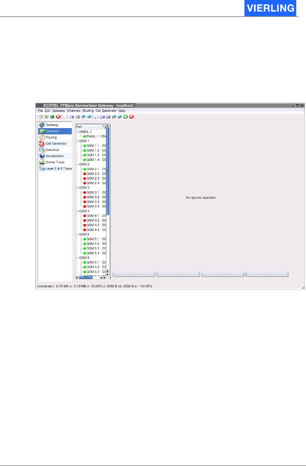
10. Channels
After a successful connection and selection of the “Channels” item on the left side the
following screen is visible.
The middle part shows the port overview tree. There are listedall available ports. The
amount of ports can vary depending on the installed hardware and the available license.
Generally there is a hierarchy in hardware administration of <Board> <Port> <Channel>.
E.g. the E1/T1 Card is one <Board> with four E1/T1 <Ports> and 30 <Channels> each.
In the following chapter the maximum available ports and its function are listed:
ECOTEL® VTMpro 2005-06-08 Page 27
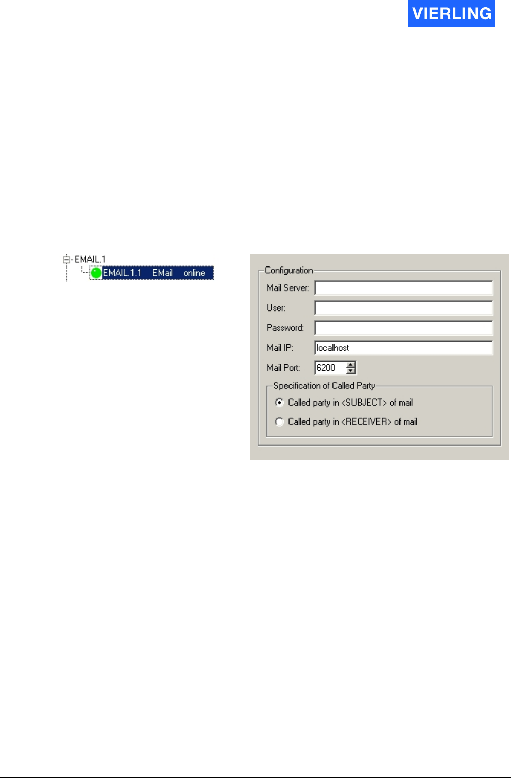
10.1
Email
If email is chosen in the tree view, the following configuration windows will be visible on
the right side:
10.1.1 General
The email port of the ECOTEL
®
VTMpro works as a client. Therefore a mail server must
be available where the ECOTEL
®
VTMpro can register at!
10.1.2 Details
Vertical Tree View:
Configuration
Attribute Description
Mail Server: The IP address of the mail server must be entered here
User: A valid user account for the ECOTEL
®
VTMpro within the mail server
must be entered here
Password The password according to the user name within the network must be
entered here
Mail IP The script providing email in the ECOTEL
®
VTMpro is internally
interfaced by a network layer, so this script can also run on a remote
hardware. If this is true the IP address of this hardware must be
entered here. Normally the email ports run on the same hardware as
the ECOTEL
®
VTMpro software so the default value must be
localhost.
Mail Port: The port the email skript can be accessed. Normally the default value
6200 must be there. See also “Mail Port”
Specification of
called party
A valid mobile number must be entered here to send an email to a
mobile by email/sms conversion. With this settings you can configure if
the destination number must be entered in the field <Subject> or
<Receiver> of the email.
ECOTEL® VTMpro 2005-06-08 Page 28
10.1.3 Usage Step by step
10.1.3.1 Settings in VTMpro
1. Enter the mail server’s address in the field “Mail Server” in form of an IP or a
known name within the network. E.g. 172.16.1.114 or EmailServer.
2. Enter a valid user of the mail system in the field “User”. The ECOTEL
®
VTMpro
mail manager will poll this account every 5 seconds and checks whether there is a
valid message to convert. After polling the mails are not available at the account
anymore!
3. Enter the valid password for the email account
4. The other values can be default!
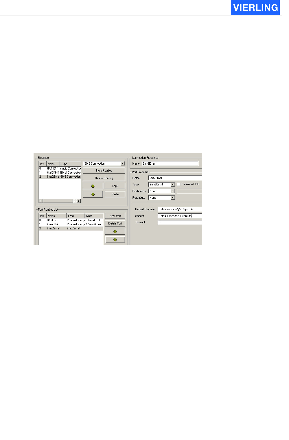
10.1.3.2 Example SMS-Email
10.1.3.2.1 Routing
For a proper function a routing for SMS-Email conversion must be available.
1. Select Routing at the vertical icon bar
2. Press the button New Routing, Select “SMS Connection” from the properties
above and enter an individual name in the Connection Properties -> Name
3. Press New Port beside the Port Routing list.
4. Enter an individual name and choose Channel Group type from the Port Properties
menu.
5. Assign to the Channel Group at least one GSM channel the SMS can be received.
More channels are possible.
6. Press New Port beside the Port Routing list again.
7. Enter an individual name and choose Channel Group type again from the Port
Properties menu.
8. Assign to the Channel Group the Email channel, the email can be sent trough.
9. Press New Port beside the Port Routing list again.
10. Enter an individual name and choose SMS2Email type from the Port Properties
menu. Set a default receiver email address if the received SMS bears no specific
receiver. Set also a default sender that will be set within the created email by
VTMpro. The timeout in seconds can be set different to zero, when a new attempt
shall be made when no confirmation is received from the mail server that the email
has been sent.
11. Press “Activate Routing on Gateway” from the horizontal icon bar.
10.1.3.2.2 Structure of SMS
The SMS must contain the destination email address at the beginning of the text. The
email address must be in brackets. The same rule exists for the sender. A sender address
ECOTEL® VTMpro 2005-06-08 Page 29
can be set in the same way at the beginning of the SMS. This address will be set into the
sender field of the email. After the brackets the user text can be written.
Example:
The Text “Hello World” shell be sent by SMS from the origin Sender@VTMpro.de to the
destination Receiver@VTMpro.de. The SIM with the CLI 0160/1234567 within the
gateway will be used.
Solution:
Text: <Receiver@VTMpro.de><Sender@VTMpro.de> Hello World
Send to Mobile: 0160/1234567
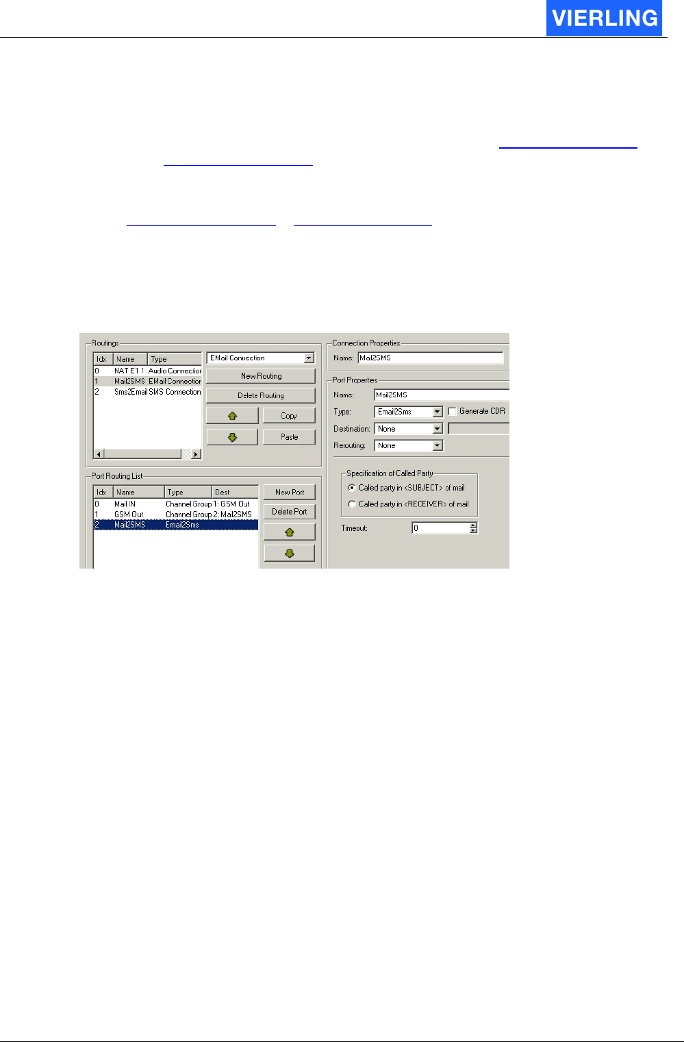
10.1.3.3 Example Email-SMS
Routing
For a proper function a routing for Email-SMS conversion must be available.
1. Select Routing at the vertical icon bar
2. Press the button New Routing, Select “EMail Connection” from the properties
above and give an individual name in the Connection Properties -> Name
3. Press New Port beside the Port Routing list.
4. Enter an individual name and choose Channel Group type from the Port Properties
menu.
5. Assign to the Channel Group the Email channel the email can be received
through.
6. Press New Port beside the Port Routing list again.
7. Enter an individual name and choose Channel Group type again from the Port
Properties menu.
8. Assign to the Channel Group at least one GSM channel the SMS can be sent.
More channels are possible
9. Press New Port beside the Port Routing list again.
10. Enter an individual name and choose Email2SMS type from the Port Properties
menu.
11. Choose whether there is the called party in subject or receiver field of the mail.
The timeout in seconds can be set different to zero, when a new attempt shall be
made when no confirmation is received from the network provider that the SMS
has been sent.
12. Press “Activate Routing on Gateway” from the horizontal icon bar.
ECOTEL® VTMpro 2005-06-08 Page 30
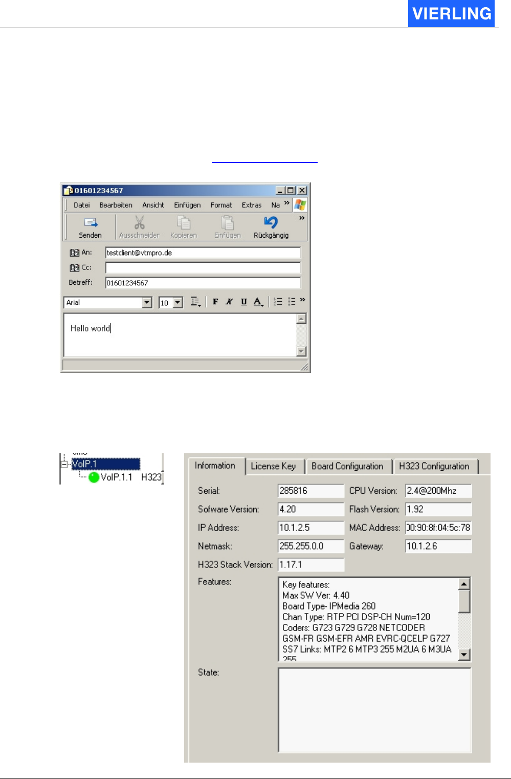
10.1.3.3.1 Structure of Email
The email must be directed to the mail client that is registered for ECOTEL
®
VTMpro at
the mail server in the network. This client must be entered into the receiver field of the
email. The destination CLI of the mobile has to be set in default i to the subject field of the
email. The Text can be written into the text field.
Example:
The message “Hello world” shall be sent to the mobile user CLI 0160/1234567 via the
ECOTEL
®
VTMpro mail client testclient@vtmpro.de.
Solution:
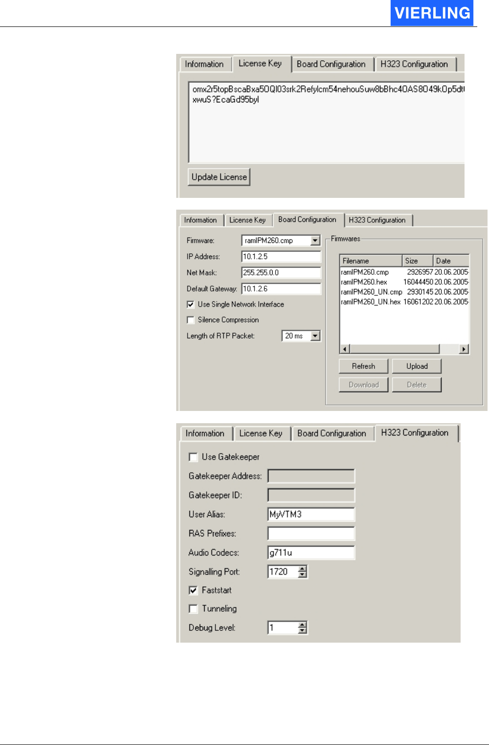
10.2
VoIP
If VoIP is chosen in the tree view, the following configuration windows will be visible on the
right side for VoIP.
Vertical Tree View: Configuration Panel:
ECOTEL® VTMpro 2005-06-08 Page 31

ECOTEL® VTMpro 2005-06-08 Page 32
10.2.1 Information
Attribut: Description:
Serial Displays the serial number of the mounted VoIP Board for
identification aims or CODEC upgrade
Software Version Displays the software version of the VoIP board
Flash Version Displays the version of the firmware on the VoIP board
CPU Version Displays the parameter of the VoIP board CPU
MAC Address Displays the hardware address of the VoIP board
H.323 Stack Version
Displays the version of the used h.323 stack.
Features Displays other features of the used VoIP card. Especially there are
listed all licensed CODECS. If there are problems in using CODECS
check here if the used CODEC is installed!
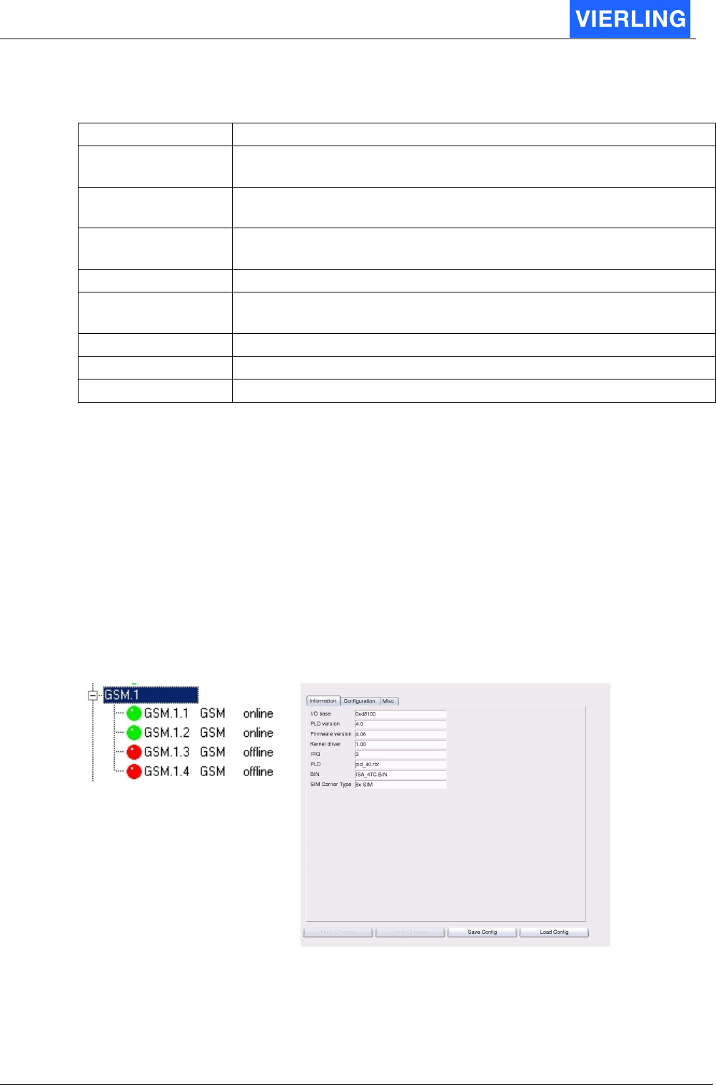
10.2.2 License Key
For providing additional CODECs there is a license key necessary. The key string must be
entered in to the field and the “Update License” button must be pressed to activate the
CODEC.
10.2.3 Board Configuration
Attribut: Description:
Firmware The used firmware can be chosen in this field. The available firmware
versions are visible in the field on the right side of the window.
Normally this is very useful when an update is uploaded to the
gateway
IP adress This is the IP address of the VoIP port for signaling and audio data
Net Mask This is the mask for IP address decoding. Settings belong to the
network architecture
Default Gateway Set the default gateway for the network ECOTEL
®
VTMpro is installed
Use Single
Network
Interface
Normally the VTMpro needs an own public IP address for VoIP
service. By using an internal NAT service and providing a network
switch it is possible to use only one public IP for remote access and
VoIP. In this case a unique local IP address must be entered in the “IP
address” field of the VoIP card .
Silence
Compression
This setting enables the silence compression in G.711 codec. This
feature provides the option of saving bandwidth and data amount
when there is silence in the traffic channel
Length of RTP
Packet
This setting enables to choose the length of the real time protocol
packets. Short packets generate more overhead but the chance is
given that a loss of single packets will not effect the quality of voice too
much
ECOTEL® VTMpro 2005-06-08 Page 33
10.2.4 VoIP Configuration
Attribut: Description:
Use Gatekeeper If a gatekeeper for traffic distribution in the system is available then
choose this box
Gatekeeper Address
If gatekeeper is chosen then a valid IP address must be entered
here
Gatekeeper ID If the gatekeeper provides a ID or name this can be entered here.
This parameter is optional.
User Alias The name of the gateway must be entered here. This RAS Prefix
Audio Codecs The used codecs must be entered in this field as a string separated
by spaces. E.g. G723
Signalling Port Configures the port the h.323 signaling is working
Fast Start Enables the h.323 fast start option
Tunneling Enables the h.245 tunneling option
10.2.5 Firmware
Shows the provided firmware for the VoIP card. Normally the loaded firmware may not be
changed and can be set at default values.
10.3
GSM
The GSM card has got board level and port level configuration settings.
10.3.1 Board Control Panel
Selecting the board in the tree view shows the board level settings:
Vertical Tree View:
GSM Board Configuration Panel:

ECOTEL® VTMpro 2005-06-08 Page 34
10.3.1.1 Configuration
Tone Config
Settings for the in-band signaling tone recognition. The tone recognition is characterized
by the base tone and the window size. There are three combo boxes available. The upper
wide box provides the chance to use preconfigured settings for base tone and window
size or to realize user defined configuration:
Name: Basetone in Hz Windowsize in Hz
Continental 400 25
US/UK 350 125
User defined <User Settings> <User Settings>
If one of the user defined settings has been chosen, then the values in the table are valid.
For “User defined” settings own values must be entered in the two additional combo
boxes. The left one sets the basetone and the right one the windowsize.

ECOTEL® VTMpro 2005-06-08 Page 35
A
TTENTION
Increasing the windowsize increases the probability of recognizing the alert
tone, but increases also the possibility of interpreting any noise as an alert tone!
Configure Hardware On Startup
ECOTEL
®
VTMpro provides the possibility to configure hardware with default or individual
settings for each board. If individual values must be used then this box must be checked
and the following values must also be set.
IRQ
Sets the Interrupt for the specific board. The value –1 uses the default value. Normally no
changes must be done at this configuration. Any changes have to be done very carefully
to prevent hardware conflicts.
PLD file
This setting locates the used firmware for the programmable logic on the board. There is
also the chance to use a default firmware by electing “default” in the combo box or the use
of a specific file. The choice is limited to the available files with the ending “
<name
>.pdf”
visible in the “firmwares” listbox on the right side.
A
TTENTION
A change will be valid first after a reboot of the gateway!
BIN file
This setting locates the used firmware for the controller on the board. There is also the
chance to use a default firmware by selecting “default” in the combo box or the use of a
specific file. The choice is limited to the available files with the ending “
<name>
.bin” visible
in the “firmwares” listbox on the right side.
A
TTENTION
A change will be valid first after a reboot of the gateway!
Firmware
Provides the opportunity to administrate different firmware version for this board. The
actual available firmware can be seen in the “Firmware” list box .
Refresh
Refreshes the view of the list box containing the firmware.
Upload
Provides the possibility to upload a new firmware from the host running the ServiceGear
software to the actual controlled gateway.

ECOTEL® VTMpro 2005-06-08 Page 36
Download
Provides the possibility to download a firmware from the actual controlled gateway to the
host running the ServiceGear software. The firmware which should be downloaded must
be marked in the list box.
Delete
Provides the possibility to delete a firmware on the actual controlled gateway. The
firmware which should be deleted must be marked in the list box.
A
TTENTION
Deletion of a firmware that is actual used causes trouble at the next reboot,
because the specific board will not be able to run anymore!
Information
Provides hardware informations:
I/O Base
Displays the used adress of the specific board on the isa-bus.
PLD version
Displays the version of the used file for the programmable logic device on the board.
Driver version
Displays the version of the used file for the controller on the board.
IRQ
Displays the used interrupt of the board within the host computer.
PLD
Displays the filename of the used firmware for the PLD.
A
TTENTION
The displayed filename and the set filename in the configuration menu can
differ, because the settings will be valid not before the gateway has been
restarted!
BIN
Displays the filename of the used firmware for the microcontroller of the board.
A
TTENTION
The displayed filename and the set filename in the configuration menu can
differ, because the settings will be valid not before the gateway has been
restarted!
ECOTEL® VTMpro 2005-06-08 Page 37
10.3.1.2 Misc
Reset Board
Provides the possibility to reset the whole board. The reset is straight connected to the
reset pin of the boards controller. If this button will be pressed all four channels on the
board are affected.
Development
Provides direct settings of commands as strings. Use only for experts and development!
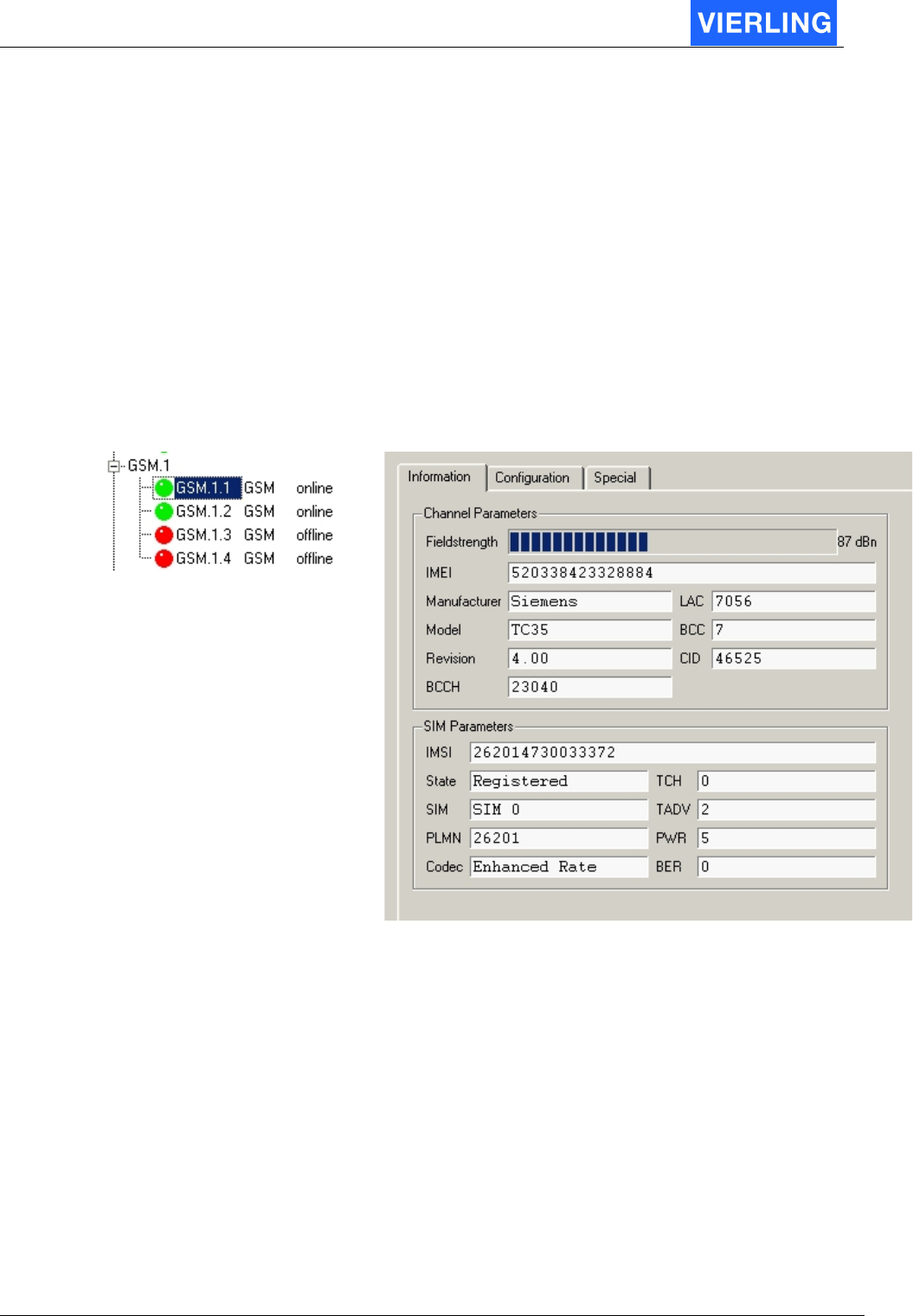
10.3.2 Channel Control Panel
Vertical Tree View:
Board Configuration Panel:
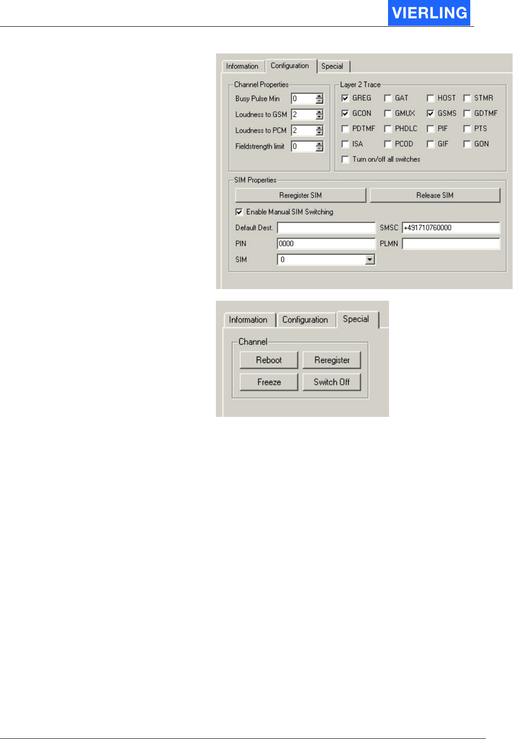
ECOTEL® VTMpro 2005-06-08 Page 38
10.3.2.1 Channel Properties
Provides channel specific settings
Busy Pulse Min
In case of in-band signaling detection it has mainly to be differentiated between busy-tone,
alert-tone and any other signals categorized as voice-tone. The detection algorithm works
like this: If there is a valid signal in the voice path (matching frequency) then it has to be
decided according to the pulse/pause ratio whether it is an alert signal or busy. If the
frequency does not match then it is be messaged to the host as a voice-announcement. In
case of limited parameters only the busy-pulse minimum length is configurable. The delta
between minimum length and maximum valid length is fix (200 ms). If the pulse length is
between <BusyPulseMin> and <BusyPulseMin+200 ms> then it is a valid busy signal and
will be transferred to the host. If it is longer then it is an alert signal, if shorter it is invalid!
The entered format is coded as following: The number entered is multiplied internal with
40 ms. So entering 1 means 40 ms, 15 means 600 ms!