VIERLING Communications ECVTM-PRO Cellular Gateway System User Manual Part I
VIERLING Communications GmbH Cellular Gateway System Users Manual Part I
Contents
- 1. Users Manual Part I
- 2. Users Manual Part II
- 3. Users Manual Part III
Users Manual Part I

ECOTEL
®
Antenna Installation Instructions
Edition 2.0
VIERLING Communications GmbH
70459.210/20 - 2.0 – 20050713

VIERLING
Page 2 70459.210/20 - 2.0 – 20050713 – ECOTEL
®
VIERLING Communications GmbH
Pretzfelder Strasse 21, D-91320 Ebermannstadt
Postbox 11 65, D-91316 Ebermannstadt
Phone: +49 (0) 91 94 - 97 -0
e-Mail: info@vierling.de
Internet: http://www.vierling.de
© 2005 VIERLING Communications GmbH, Ebermannstadt
All rights reserved. Any dissemination, reproduction or processing of this
document or its contents or excerpts from it, regardless of the procedure
used, is prohibited without prior written permission of VIERLING
Communications GmbH.
We reserve the right to make changes without prior notice.
This text was conscientiously prepared. However, VIERLING
Communications GmbH assumes no liability should it nevertheless
contain errors.
VIERLING
ECOTEL
®
- 70459.210/20 - 2.0 – 20040913 Page 3
Contents
1. INTRODUCTION.........................................................................5
2. SELECTING A LOCATION.........................................................6
3. INFORMATION FOR INSTALLING THE ANTENNA .................7
3.1 Attenuation Values of Antenna Cables....................................7
3.2 Antennas ..................................................................................10
3.2.1 GSM/UMTS omnidirectional Antenna.............................10
3.3 Antenna Installation ECOTEL
®
VTM pro ................................12
3.3.1 Antenna Mast....................................................................13
3.3.2 Surge Protection ..............................................................13
3.4 Calculating the Cable Attenuation .........................................16
3.5 Antenna Installation VT-Multi Channel..................................17
3.6 Installing the Antenna Cable ..................................................18
4. ICNIRP/MPE COMPLIANCE ....................................................20
4.1 ICNIRP/MPE Limits ..................................................................20
4.2 Absolute Maximum Power Output of VTM32........................21
4.3 Maximum Power Output of VTM32 (US Version) .................23
4.3.1 System under operational conditions............................23
4.3.2 System under worst case conditions.............................23
VIERLING
Page 4 70459.210/20 - 2.0 – 20050713 – ECOTEL
®
4.4 Safety Distance........................................................................24
4.4.1 Calculation........................................................................24
4.4.2 FCC Compliance ..............................................................24
4.5 Country Specific Regulations ................................................25

VIERLING
ECOTEL
®
- 70459.210/20 - 2.0 – 20040913 Page 5
1. Introduction
During design of ECOTEL
®
VTM, special attention was given to simple
assembling and easy access to the operating interfaces.
Certain considerations must be observed however when installing the
various interfaces.
This application sheet offers practical suggestions for the installation of
antennas.
IMPORTANT NOTE:
To comply with FCC RF exposure compliance requirements,
the following antenna installation and device operating
configurations must be satisfied:
a) The antennas used for this transmitter are to be fixed-
mounted on outdoor permanent structures.
b) The device must operate with the specific antennas
described in section 3.2 of this document
c) The antennas used for this device must be installed to
provide 1 meters from all persons and the antenna gain
must not exceed 2 dBi.
e) The device must operate in the transmitter co-location
configurations identified in section 3.5 of this document
VIERLING
Page 6 70459.210/20 - 2.0 – 20050713 – ECOTEL
®
2. Selecting a Location
The location of ECOTEL
®
should be chosen based on the following criteria
(listed in the order of priority):
• Close to the antenna (10 m up to 50 m)
• Close to the PBX / switch -system (up to 200 m phone cable for ISDN
(BRI/PRI))
VIERLING
ECOTEL
®
- 70459.210/20 - 2.0 – 20040913 Page 7
3. Information for Antenna Installation
3.1 Attenuation Values of Antenna Cables
Antenna cables exhibit very marked differences with regard to attenuation.
When assembling, care should be taken to use a short antenna cable. If
space requirements do not permit, then a cable with less attenuation must be
used.
Cable Diamet
er
min.
Radius
850 MHz 1900 MHz Order No.
RG-178B/U
140 dB/100 m
RG-174/U
90 dB/100 m
RG-58C/U
5,0 mm 30 mm 50 dB/100 m 74 dB/100 m
RG-213/U
10,3 mm 110 mm 23 dB/100 m 35 dB/100 m
AirCell 7
7,3 mm 25 mm 21 dB/100 m 32 dB/100 m
AirCom
Plus
10,8 mm 55 mm 12 dB/100 m 25 dB/100 m 27741.193
An attenuation of 3 dB equals 50% field strength
Attenuation = 10 lg (input power/ output power) dB
Field Strength Spectrum:
-113 dB ... -95 dB insufficient field strength
-95 dB ... -70 dB sufficient field strength
-70 dB ... -51 dB optimal field strength (best voice quality)
(The power control of the GSM network tries to get a signal about –70 dBm)

VIERLING
Page 8 70459.210/20 - 2.0 – 20050713 – ECOTEL
®
Receive Field Strength (dBm/RxLev):
P
dBm
= (RxLev *2 –113) dBm
Output Power (dBm/PwrLev)
For 900 MHz: P
dBm
= 33 – (PwrLev –5)*2
For 1800 MHz: P
dBm
= 30 – PwrLev *2
The translation of power values in dBm to Watt:
P
W
= 0,001 W * 10 ^ (P
dBm
/10)
Receive Field Strength (RSSI / dBm)
RSSI dBm RSSI dBm
0 -113 16 -81
1 -111 17 -79
2 -109 18 -77
3 -107 19 -75
4 -105 20 -73
5 -103 21 -71
6 -101 22 -69
7 -99 23 -67
8 -97 24 -65
9 -95 25 -63
10 -93 26 -61
11 -91 27 -59
12 -89 28 -57
13 -87 29 -55
14 -85 30 -53
15 -83 31 -51

VIERLING
ECOTEL
®
- 70459.210/20 - 2.0 – 20040913 Page 9
GSM and UMTS Frequencies
GSM
Band Uplink (MHz) Downlink (MHz) Bandwidth
GSM450 450,4-457,6 460,4-467,6 200 kHz
GSM480 478,8-486 488,8-496 200 kHz
GSM750 777-792 747-762 200 kHz
GSM850 824-849 869-894 200kHz
GSM-R 876-880 921-925 200kHz
EGSM900 880-890 925-935 200kHz
PGSM900 890-915 935-960 200kHz
DCS1800 1710-1785 1805-1880 200kHz
PCS1900 1850-1910 1930-1990 200kHz
UMTS
Band Uplink (MHz) Downlink (MHz) Duplex-Distance
I 1920- 1980 2110 – 2170 190 MHz
II 1850 - 1910 1930 – 1990 80 MHz
III 1710 - 1785 1805 – 1880 95 MHz
VIERLING
Page 10 70459.210/20 - 2.0 – 20050713 – ECOTEL
®
3.2 Antennas
For the US market only the Kathrein 800 10147 order code VPol Omni 824–
960/1805–2170 360° 2dBi is certificated for operation with ECOTEL®VTM
pro.
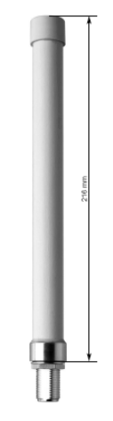
3.2.1 GSM/UMTS omni directional Antenna
(Order Number 70459.112)
Technical data
Mechanical parameter
Colour RAL 7035 (light-grey)
Dimensions 216 x 20 mm
Weight 0,250 kg
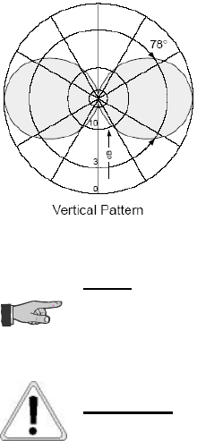
Electrical parameter
Frequency I 824 –960 MHz
Frequency II 1805 -2170 MHz
Gain 2 dBi (max 6,5 dBi)
Impedance 50 Ohm
Match/VSWR <2:1
Max. power 50 W
Polarisation vertical
Connector N female
VIERLING
ECOTEL
®
- 70459.210/20 - 2.0 – 20040913 Page 11
Antenna Diagram
N
OTE
:
The antenna is a 850/1900 MHz antenna. To get the best
reception, the antenna must be mounted vertical!
A
TTENTION
:
This antenna does not support GSM1800
VIERLING
Page 12 70459.210/20 - 2.0 – 20050713 – ECOTEL
®
3.3 Antenna Installation ECOTEL
®
VTM pro
ECOTEL
®
VTM pro should be mounted as close to the antenna system as
possible (maximum antenna length: 50 m). The antenna at the serving GSM-
cell should be visible from the mounting position.
ECOTEL®VTM pro provides an individual RF connector for each antenna.
For a distance of up to 30 m a RG 58 antenna cable is sufficient. Longer
distances could only be obtained with a AirCel/AirCom cable. Adapters for
SMA to N or SMA to FME are necessary to link the different cable diameters.
To simplify the antenna installation a antenna installation package is
available. (Order Number 70466.401).
The antenna installation set comprises:
GSM850/1900/UMTS Order Number 70459.112
Adapter FME-SMA : Order Number 47560.915
Adapter N-female/SMA-female: Order Number 47560.020
N-male for AirCom Plus: Order Number 47560.018
N-female for AirCom Plus: Order Number 47560.019
The maximum length of antenna cable has to be calculated before
installation! (see section 3.4)
VIERLING
ECOTEL
®
- 70459.210/20 - 2.0 – 20040913 Page 13
Mounting Position
The installation of the antennas should be done as close as possible to the
GSM-gateway. The RF-cable length should be not longer than 50 m.
distance between antennas > 0,2 m;
distance to bottom (roof) > 1 m;
distance to lightning protectors > 5 m;
distance to the base station > 20 m
3.3.1 Antenna Mast
The antennas could be mounted on one antenna mast. If it is not possible or
allowed to install the antenna mast direct on the roof of the building, small
foundations out of cement could be used to fix the antenna mast on the roof.
In this case the mast should be not higher than 2 m to avoid problems with
wind. The mast must be grounded.
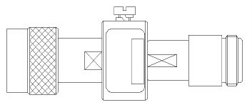
3.3.2 Surge Protection
The antenna system could be hit by lightning. Therefore the antenna must be
protected against over voltage. A surge protector limits the risk of over
voltage for most cases. For a complete protection an insurance which covers
the possible financial loss could be arranged.
Surge Protector (N-femal/male connector)
frequency range: DC to 2500 MHz
return loss: ≥ 20dB
insertion loss: ≤ 0,2dB
impedance: 50 Ohm
VIERLING
Page 14 70459.210/20 - 2.0 – 20050713 – ECOTEL
®
surface: sucoplate
temperature range: -40°C to +100°C
I
max
: 20 kA
U
max
800 V
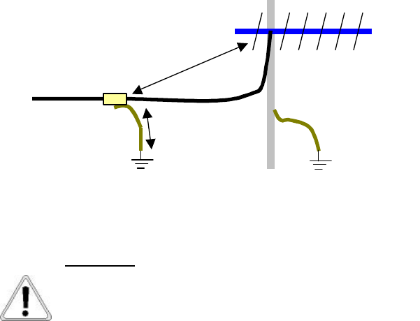
Mounting Conditions
The surge arrestor should not be mounted in cable ducts or rooms with
inflammable objects. The cable from the antenna to the arrestor must be > 5
m. The arrestor must be grounded by a 16 mm² wire with at maximum half
the length of the antenna cable length. The ground must have a low
resistance to earth. The ground must not be connected to the lightning
protector of the roof! (regulation: EN 50083)
16 mm² lground cable
lantenna cable
Protection Earth
Surge-
Protector
Mast
Lightning Protector
to
MRS
lantenna cable > 2 x lground cable
A
TTENTION
:
Protection earth and the lightning protector must be
individual, none coupled grounds. The diameter of protection
earth must be >= 16 mm².
VIERLING
ECOTEL
®
- 70459.210/20 - 2.0 – 20040913 Page 15
Supplier:
VIERLING Communications GmbH
Surge Protector
Surge Protector 20kA Order Number 47560.939
Available Adapter Cables for Antennas
Cable SMA-male - FME-female (60 cm): Order Number 47560.914
Cable SMA-male - FME-female (300 cm): Order Number 47560.920
Adapter SMA-male - FME-male: Order Number 47560.915
Cable SMA-male - SMA-male (20 cm): Order Number 47560.916
Cable SMA-male - N-male (30 cm): Order Number 47560.919
Adapter N-female - SMA-female: Order Number 47560.020
Connector N-male: Order Number 47560.018
Connector N-female: Order Number 47560.019
VIERLING
Page 16 70459.210/20 - 2.0 – 20050713 – ECOTEL
®
3.4 Calculating the Cable Attenuation
A sufficient field GSM field strength with adequate reserve, requires a
receptive field strength of > -80 dBm. In most cases, this requirement can be
met in locations where the GSM transmitting mast is visible. (As a rule, with
the transmission mast direct visibility, field strength is between –60 dBm and
–50 dB). The attenuation of the entire receiving system in this case must be
< 20 dBm (80 dBm – 60 dBm = 20 dBm), (a < -20 dB).
These values should serve as a guide. In any case, prior to installation of a
GSM antenna system, the actual field strength must be determined using a
measuring device or an ECOTEL
®
-desk-top device.
Example:
GSM Antenna +2 dB
50 m distance between antenna and ECOTEL
®
-20 dB < -2 dB + a
cable
(Total Attenuation = Antenna Gain – Attenuation of Splitter + Attenuation of
Cable)
a
cable
> -18 dB
a
AirCell 7
= -32 dB / 100 m = -16,0 dB / 50 m
a
AirCom Plus
= -25 dB / 100 m = -12,5 dB / 50 m
-> AirCel7 and AirCom cable can be used for the installation!
(RG58CU cable should not be used for this location: a
RG58CU
= -37 dB it is not
less than –18 dB !!)
VIERLING
ECOTEL
®
- 70459.210/20 - 2.0 – 20040913 Page 17
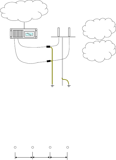
3.5 Antenna Installation VT-Multi Channel
Earth
PRI
Fixed Public Network
GSM Network
Provider A,B
GSM Network
Provider C,D
Surge-
Protector
Antenna System
Mast
Earth
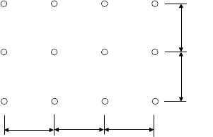
If more than one antenna is installed, the antennas can be installed in a line
or as an antenna array. In both cases the distance between the single
antenna must be >20 cm.
Antenna in line installation
> 20 cm
> 20 cm
> 20 cm
Antenna as array installation
VIERLING
Page 18 70459.210/20 - 2.0 – 20050713 – ECOTEL
®
> 20 cm
> 20 cm
> 20 cm
>20 cm
>20 cm
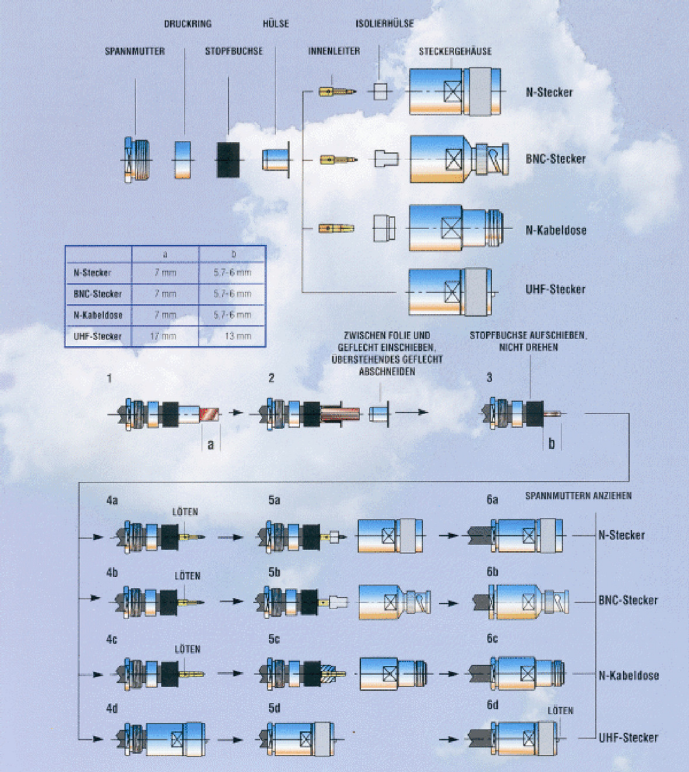
3.6 Installing the Antenna Cable
Assembling the antenna cable with N-male/N-female-connectors is shown at
Assembling antenna cable on page 19.
Directions for assembling the N-male/N-female connectors:
The N-male/N-female connector must be assembled in compliance with the
mounting instructions. Special attention should be given to inserting the
sleeve; for this, a tip:
After stripping the isolation, the copper mesh must be bent back completely.
The visible copper foil should be smoothed all around in order to facilitate
placing the sleeve over it. The somewhat smaller inside diameter of the
sleeve was intentionally designed in order to ensure an HF-conform
connection between sleeve and copper foil. Screwing the sleeve on works
satisfactorily; and screwing the nut onto the threads works in a similar
fashion.
The sleeve is parenthesized up to the limit. The copper foil hanging over
from the sleeve should now be scarified with a sharp knife and then
removed. The copper mesh must be bent back all around onto the sleeve
soil; the overhanging mesh must then be carefully cut off. Because of the
one-sided plastic-coated copper foil, the sleeve must be shoved over this foil.
Should the sleeve be shoved under the foil, then galvanic contact is not
possible!
VIERLING
ECOTEL
®
- 70459.210/20 - 2.0 – 20040913 Page 19
Tightening the tightening-nut should be very carefully done using the 2 thin
spanners (17 and 18 mm). Tightening the nut by force up to the limit results
in completely crushing the cable sleeve and the cable itself.
Assembling antenna cable

VIERLING
Page 20 70459.210/20 - 2.0 – 20050713 – ECOTEL
®
4. ICNIRP/MPE Compliance
ICNIRP (
International Commission on Non-Ionising Radiation Protection) released
limits for non ionising radiation. ECOTEL VTM gateway systems full fill all
requirements, if the access of pedestrians is restricted in an area of 3.3 m around
the antenna (the restriction can be implemented by a information plate, by fence, …).
4.1 ICNIRP/MPE Limits
Freq ICNIRP ICNIRP MPE MPE 5% MPE
MHz W
General Public Occupational General Public General Public Occupational
400-2000 MHz
1,375 f
1/2
400-2000 MHz
3 f
1/2
300-1500 MHz
1,585 f
1/2
300-1500 MHz
0,354 f
1/2
300-1500 MHz
3,545 f
1/2
850 2 40,08 V/m 87 V/m 46,2 V/m 10,32 V/m 103 V/m
900 2 41,25 V/m 90 V/m 47,55 V/m 10,62 V/m 106 V/m
400-2000 MHz
1,375 f
1/2
400-2000 MHz
3 f
1/2
300-1500 MHz
61,4 V/m
300-1500 MHz
13,69 V/m
1500-100000 MHz
137 V/m
1800 1 58,33 V/m 127 V/m 61,4 V/m 13,69 V/m 137 V/m
1900 1 59,93 V/m 130 V/m 61,4 V/m 13,69 V/m 137 V/m
MPE (maximum permissible exposure, defined by FCC):
If the RF emission of the device is lower than 5% of the MPE limit (in
mW/cm
2
), the device can be installed without extra on site measurement.
For calculation 10 V/m for the 850/900 MHz band is taken (worst case).
-> GSM band with the highest emissions and the lowest limit.
VIERLING
ECOTEL
®
- 70459.210/20 - 2.0 – 20040913 Page 21
4.2 Absolute Maximum Power Output of VTM32
GSM850/900:
Number of channels: 32
Peek Power per channel: 2 W
Effective Power Factor for GSM (Time Division Multiplex): 1/8
P
max
= 32 * 2 W * 1/8 = 8 W;
GSM1800/1900:
Number of channels: 32
Peek Power per channel: 1 W
Effective Power Factor for GSM (Time Division Multiplex): 1/8
P
max
= 32 * 2 W * 1/8 = 4 W;
UMTS:
Number of channels: 32
Peek Power per channel: 0,125 W
Effective Power Factor for UMTS: 1
P
max
= 32 * 0,125 W = 4 W;
VIERLING
Page 22 70459.210/20 - 2.0 – 20050713 – ECOTEL
®
4.3 Maximum Power Output of VTM32 (US Version)
4.3.1 System under operational conditions
GSM850/900:
Number of channels: 32
Peek Power per channel: 2 W
Effective Power Factor (Time Division Multiplex): 1/8
Effective Power Factor (Splitter/Combiner): 1
: P
operational
= 32 * 2 W * 1/8 = 8 W
4.3.2 System under worst case conditions
GSM850/900:
Number of channels: 32
Peek Power per channel: 2 W
Effective Power Factor (Time Division Multiplex): 1/8
Effective Power Factor (Splitter/Combiner): 1
: P
worst case
= 32 * 2 W * 1/8 = 8 W
VIERLING
ECOTEL
®
- 70459.210/20 - 2.0 – 20040913 Page 23
4.4 Safety Distance
4.4.1 Calculation
In the GSM850/900 band the highest energy is transmitted, so the safety
distance is calculated for the GSM850/900 band only;
P
max
= 8 W (EIRP: maximal average sending power)
P
EIRP
= 8 W * 6 dBi = 8 W * 10 (6,5/10) = 35 W
E
limit
= 10 V/m
r = sqr(30V/A * P
EIRP
) / E
= sqr(30V/A * 35 W) / 10 V/m = 3.3 m
Conditions:
Typical isotrope antenna gain = 2 dBi
Worst case isotrope antenna gain <= 6,5 dBi
As far as the cable loss is higher than the antenna gain (is full filled for
standard installations) the calculated 3.3 m safety distance also apply for this
installations.
4.4.2 FCC compliance
To fulfil FCC compliance measures for one meter distance have been
completed. The result did under-run the 100% MPE limit clear. In a
conservative consideration therefore the distance of 1m must be fulfilled for
FCC compliance. In the follow the distance for 5% MPE is 4,5m.
The operator of the gateway has to guarantee, that there is no person within
this safety area. The area has to be restricted to any persons by means of a
fence or must be marked as hazard area by black/yellow bars painted on the
ground. If the access to the area is already restricted by the location of
installation (e.g. the antenna is mounted on a roof), an information plate can
give a warning to the people which enter this restricted area.
VIERLING
Page 24 70459.210/20 - 2.0 – 20050713 – ECOTEL
®
4.5 Country Specific Regulations
The local authorities claim several other regulative handling from the
operator of a antenna system. In Germany each antenna system has to be
registered at the local office of the telecom regulation authority. Please
contact your local telecom authorities for details.