VTech Telecommunications 80-4290-00 900 MHz Cordless Phone Base Unit User Manual User Guide
VTech Telecommunications Ltd 900 MHz Cordless Phone Base Unit User Guide
UserManual.wiki
>
VTech Telecommunications
>
80 4290 00 User Manual
User Guide
Navigation menu
Upload a User Manual
Namespaces
Wiki Guide
HTML
PDF
Info
Views
User Manual
Discussion / Help
Navigation
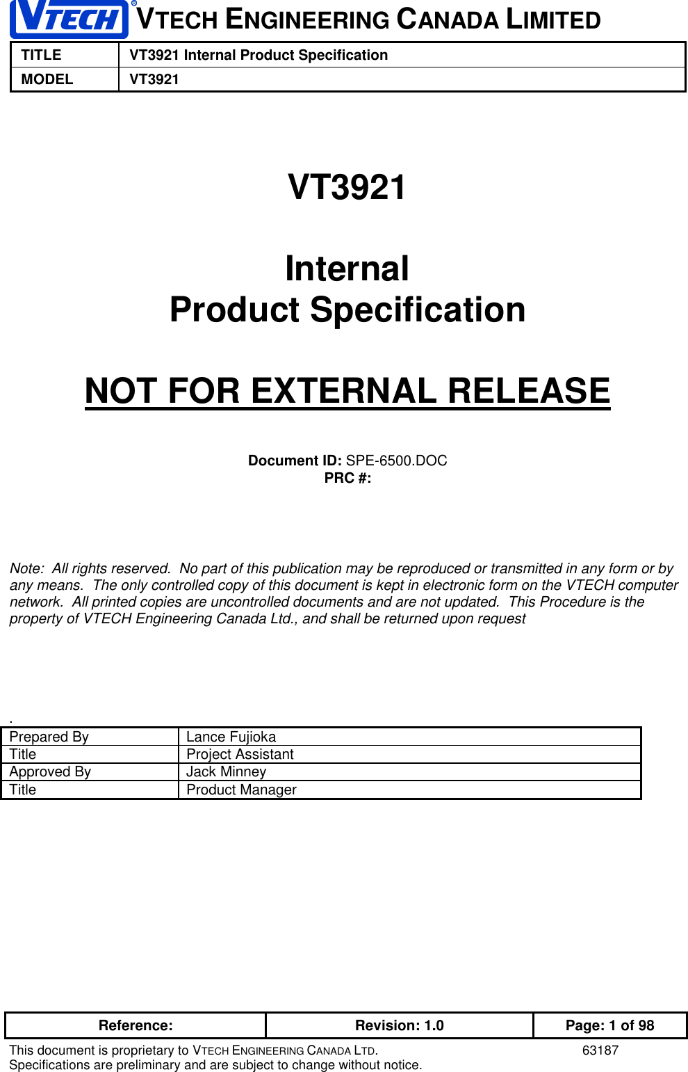
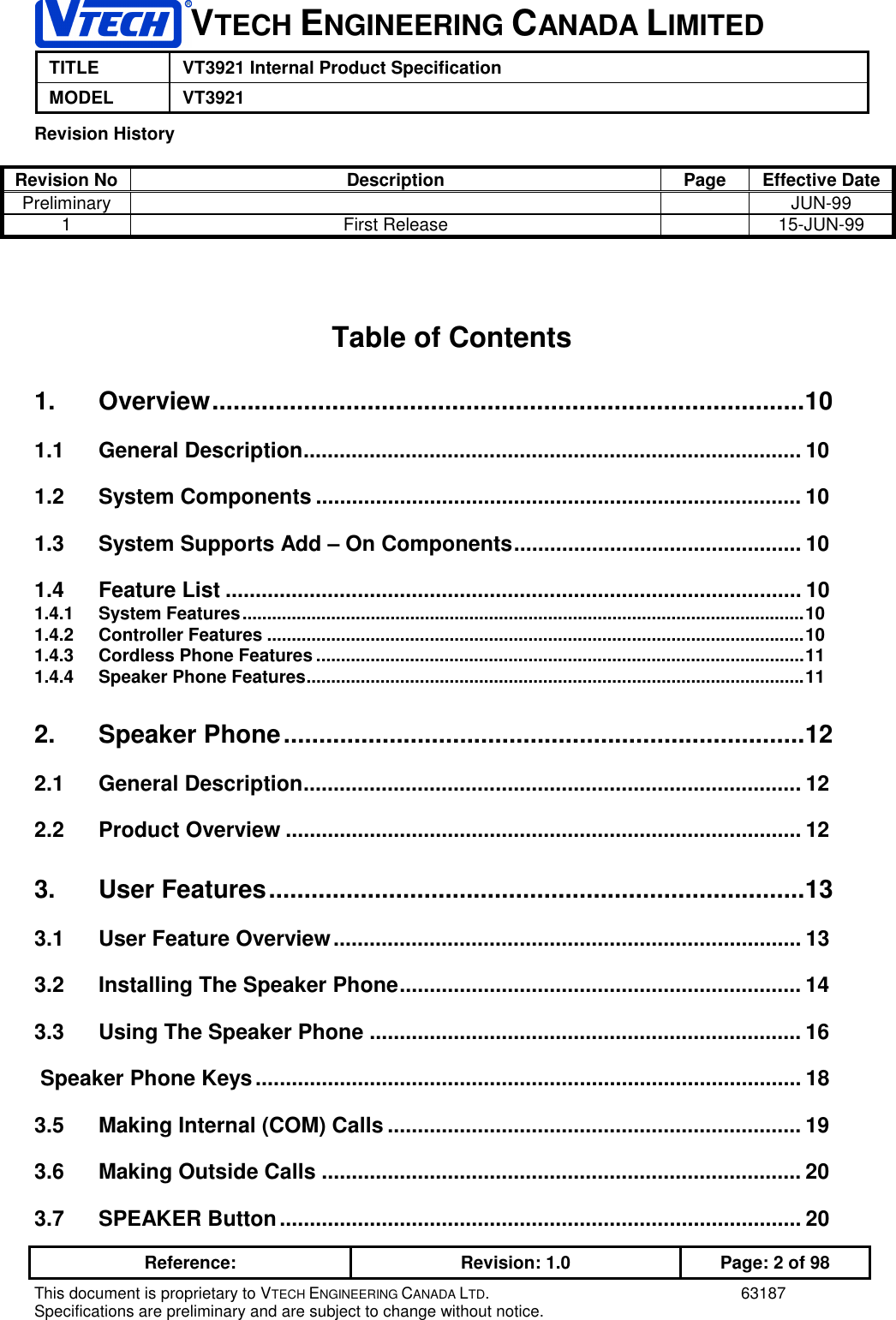
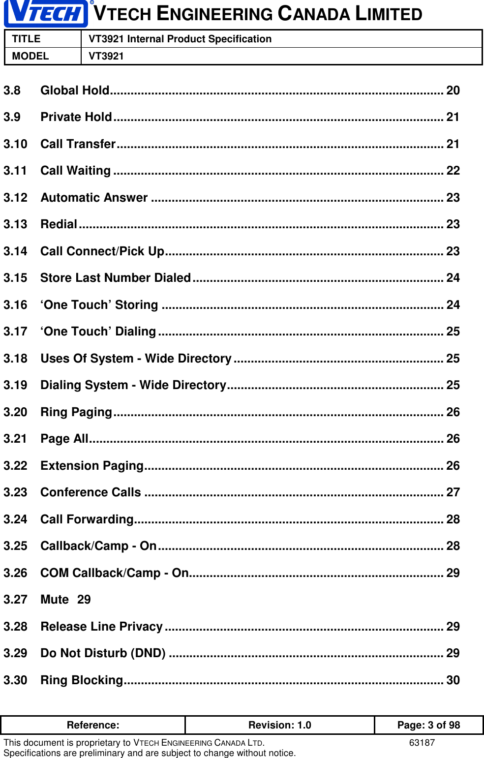
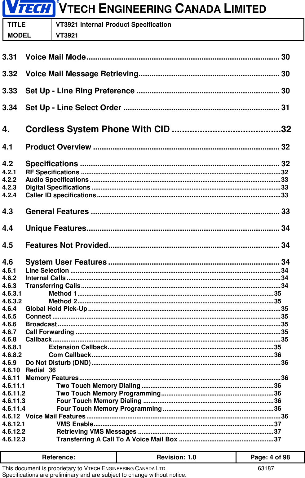
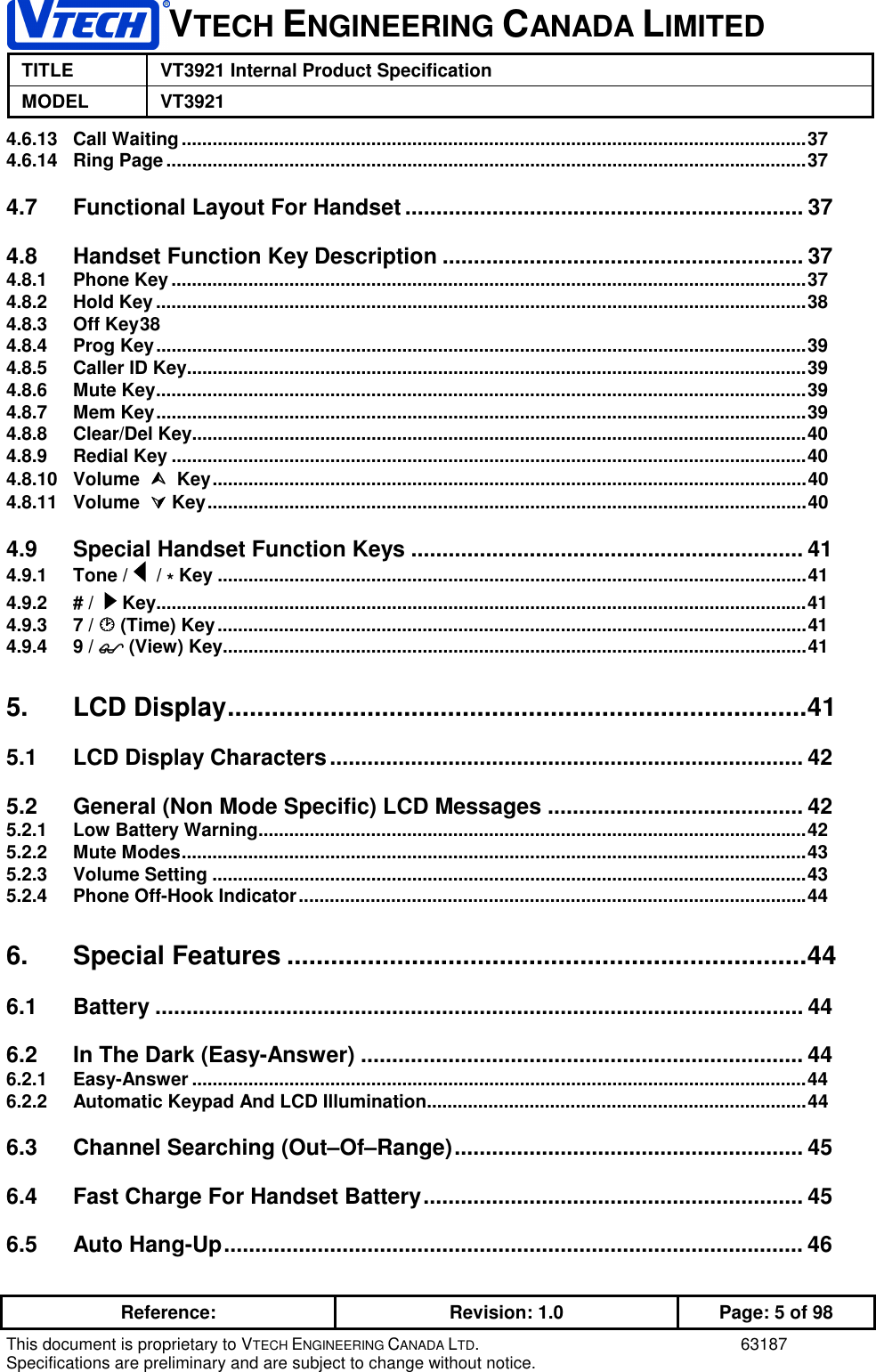
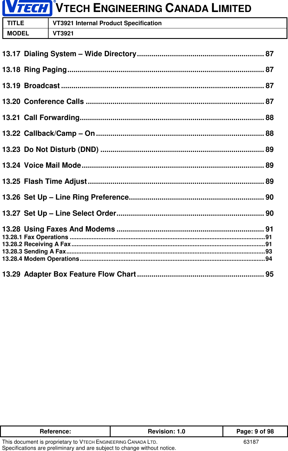
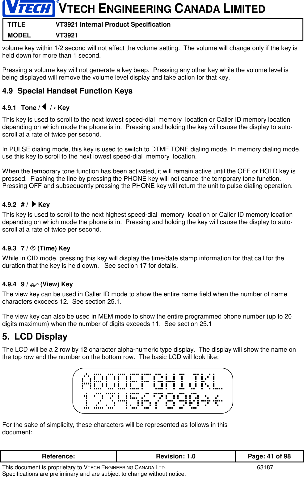
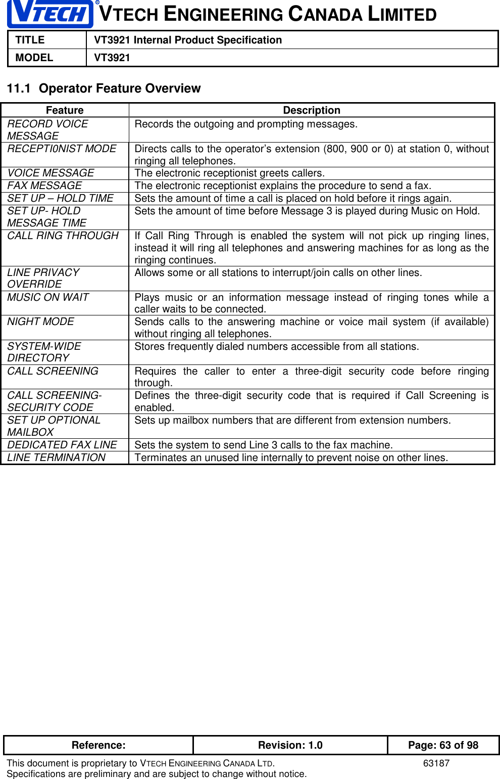
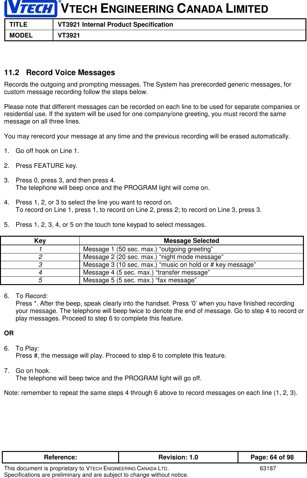
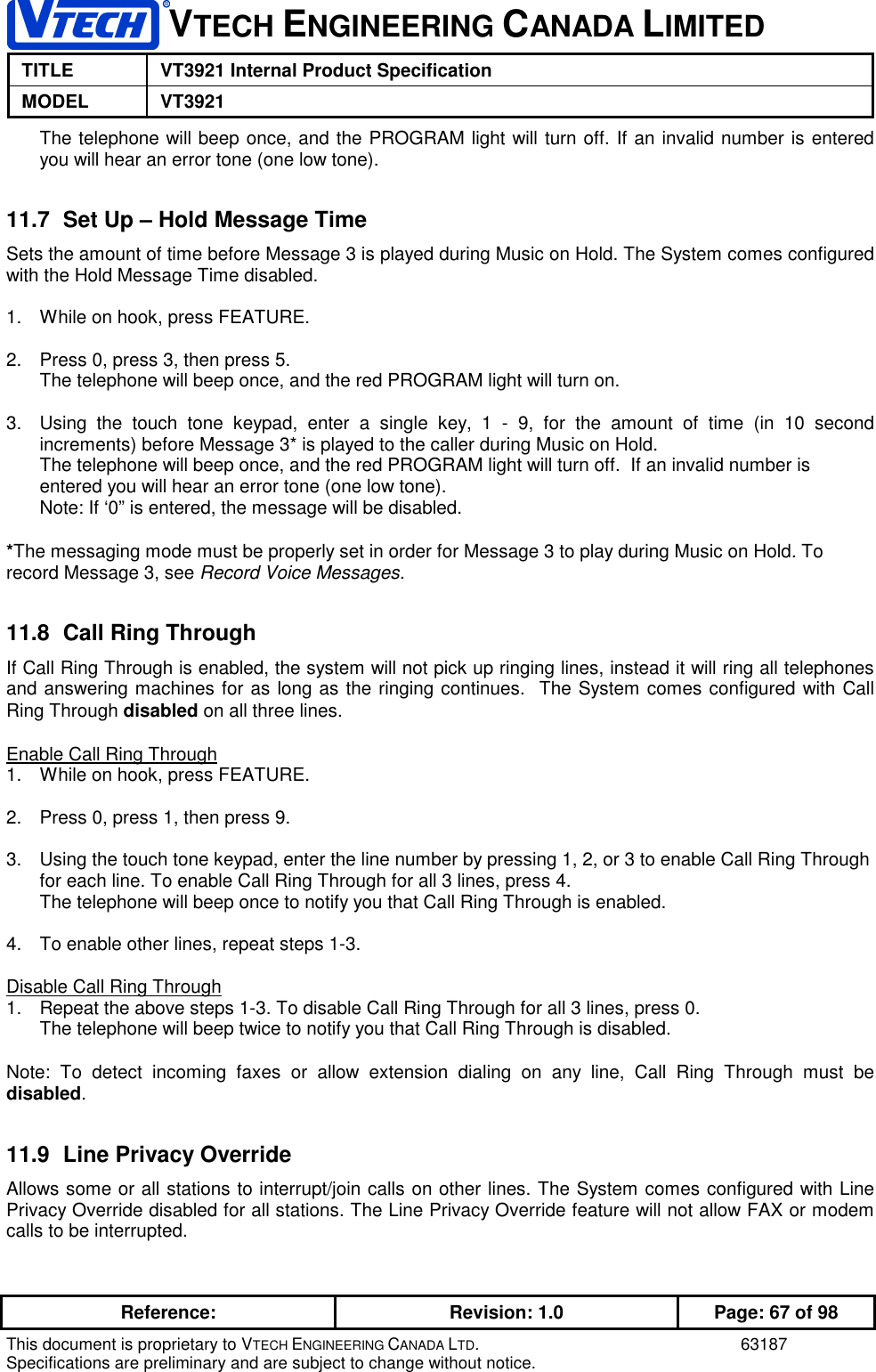
![VTECH ENGINEERING CANADA LIMITEDTITLE VT3921 Internal Product SpecificationMODEL VT3921Reference: Revision: 1.0 Page: 42 of 98This document is proprietary to VTECH ENGINEERING CANADA LTD. 63187Specifications are preliminary and are subject to change without notice.ABCDEFGHIJKL1234567890 ïïïïNote: All LCD message are left justified to provide a consistency in message presentation for the user.5.1 LCD Display CharactersAnything displayed on the LCD will be cleared off after 30 seconds of inactivity with the exception of theoperation defined in section 25.1Alpha characters shown on the display will be upper or lower case. The following symbols correspondingto a portion of those available in the standard ASCII character set can also be displayed. The charactersand symbols that can be displayed are as follows:AlphaCharacters AlphaCharacters(cont’d)AlphaCharacters(cont’d)AlphaCharacters(cont’d)Numericcharacters Symbols Symbols(cont’d)ANAn1 ‘BOBo 2ç“CPCp3 ( -DQDq 4 ) .ERE r 5 * ,FSFs6& ;GTG t 7 / :HUHu 8%=IVIv9$<JWJ w0 # >KXKx @+LYLy !MZMz ?5.2 General (Non Mode Specific) LCD Messages5.2.1 Low Battery WarningWhen the handset battery voltage drops below between 3.3[TBD] and 3.5[TBD] volts, the unit will show“LOW BATTERY” on the top line of the display.LOW BATTERYA warning tone is emitted from the handset when the phone is first activated during a low batterycondition. If the handset is being used for CID memory reviewing, Mem programming or Mem dialing, the](https://usermanual.wiki/VTech-Telecommunications/80-4290-00/User-Guide-63187-Page-42.png)