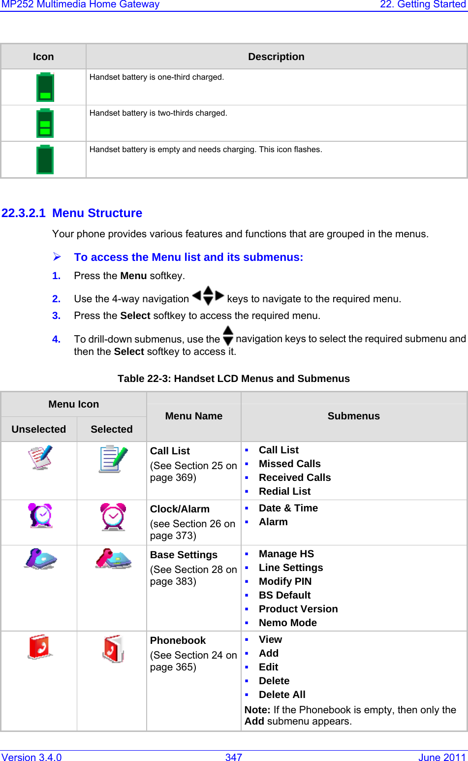
VTech Telecommunications 80-7597-00 1.9GHz Cordless Phone User Manual Users manual
VTech Telecommunications Ltd 1.9GHz Cordless Phone Users manual
UserManual.wiki
>
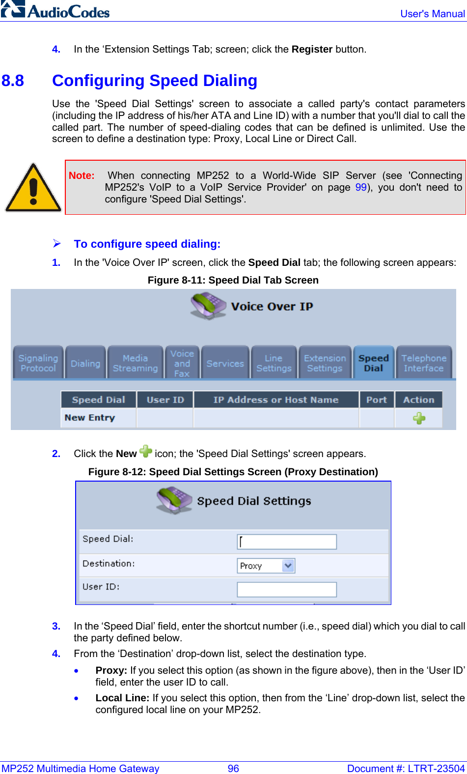
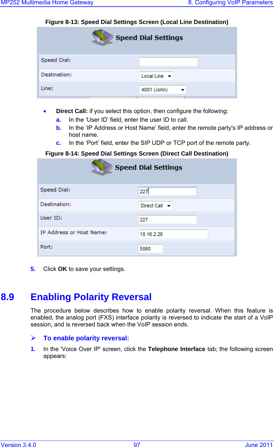
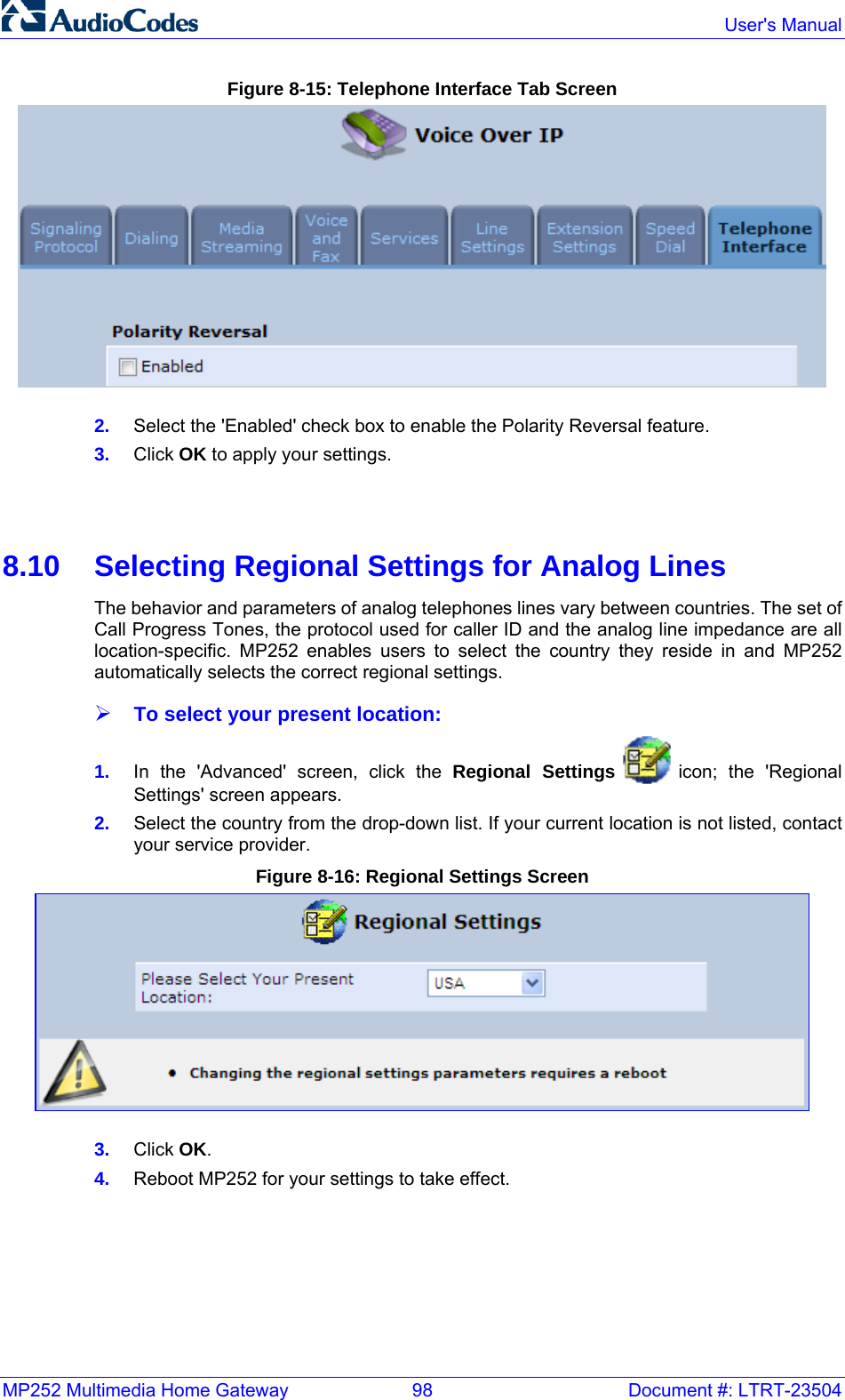
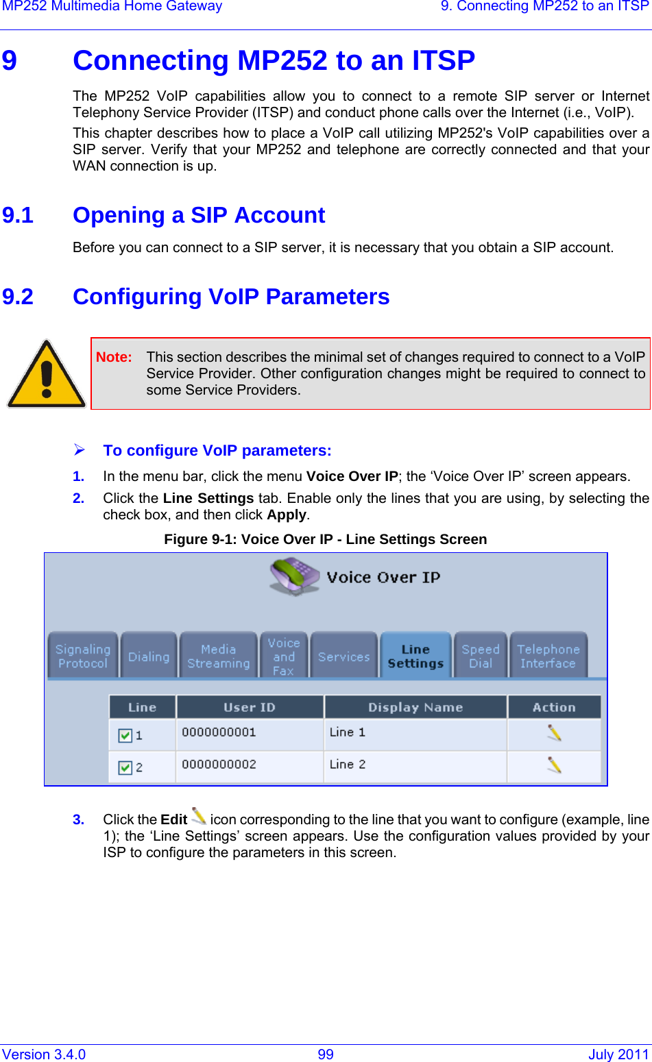
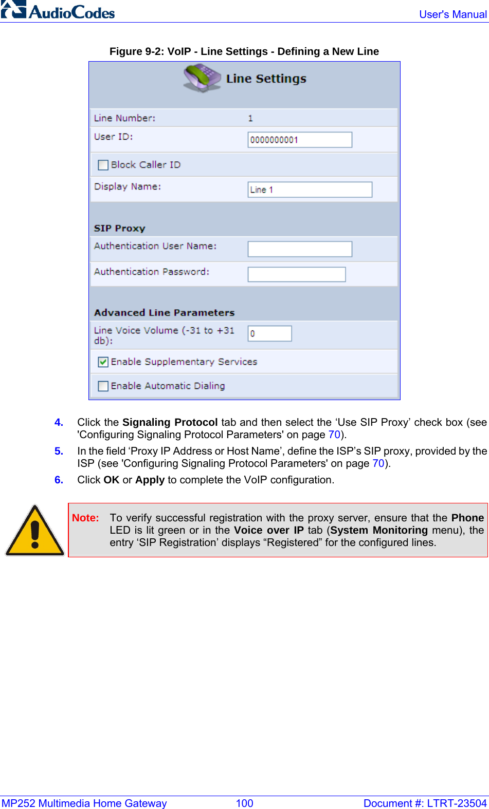
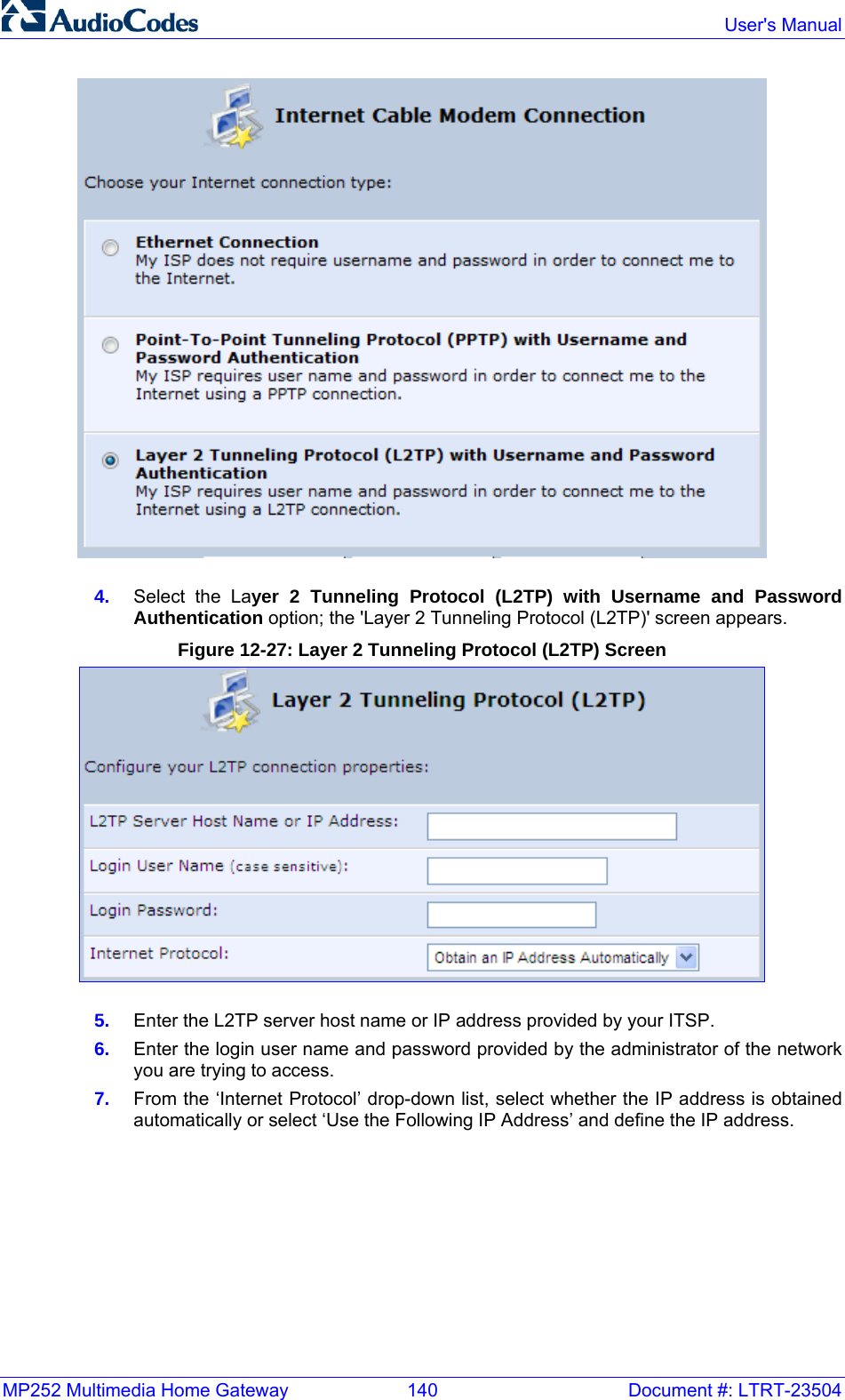
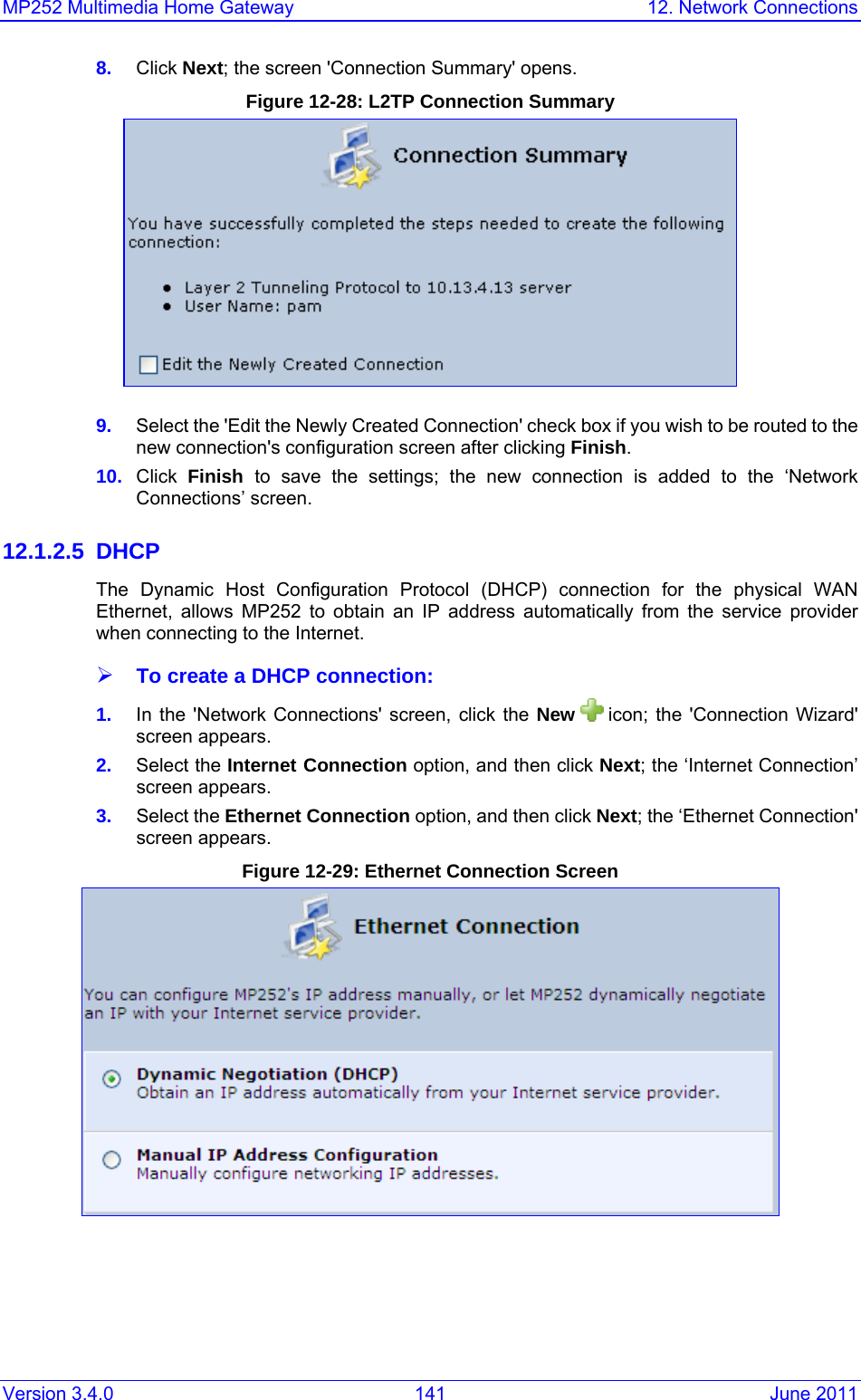
VTech Telecommunications
>
80-7597-00 User Manual
>
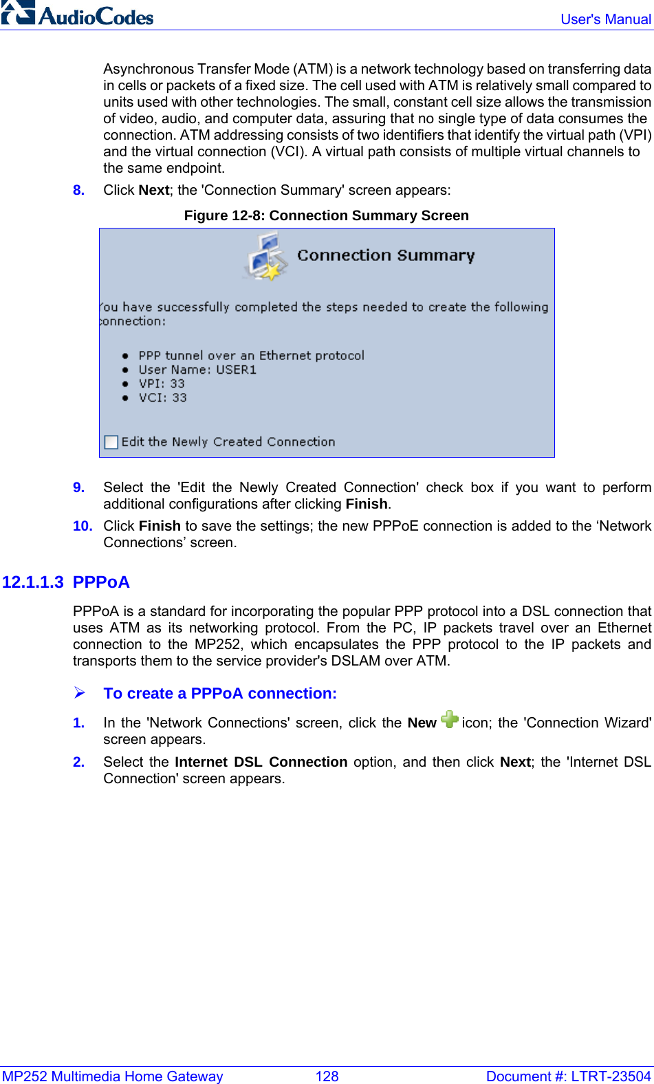
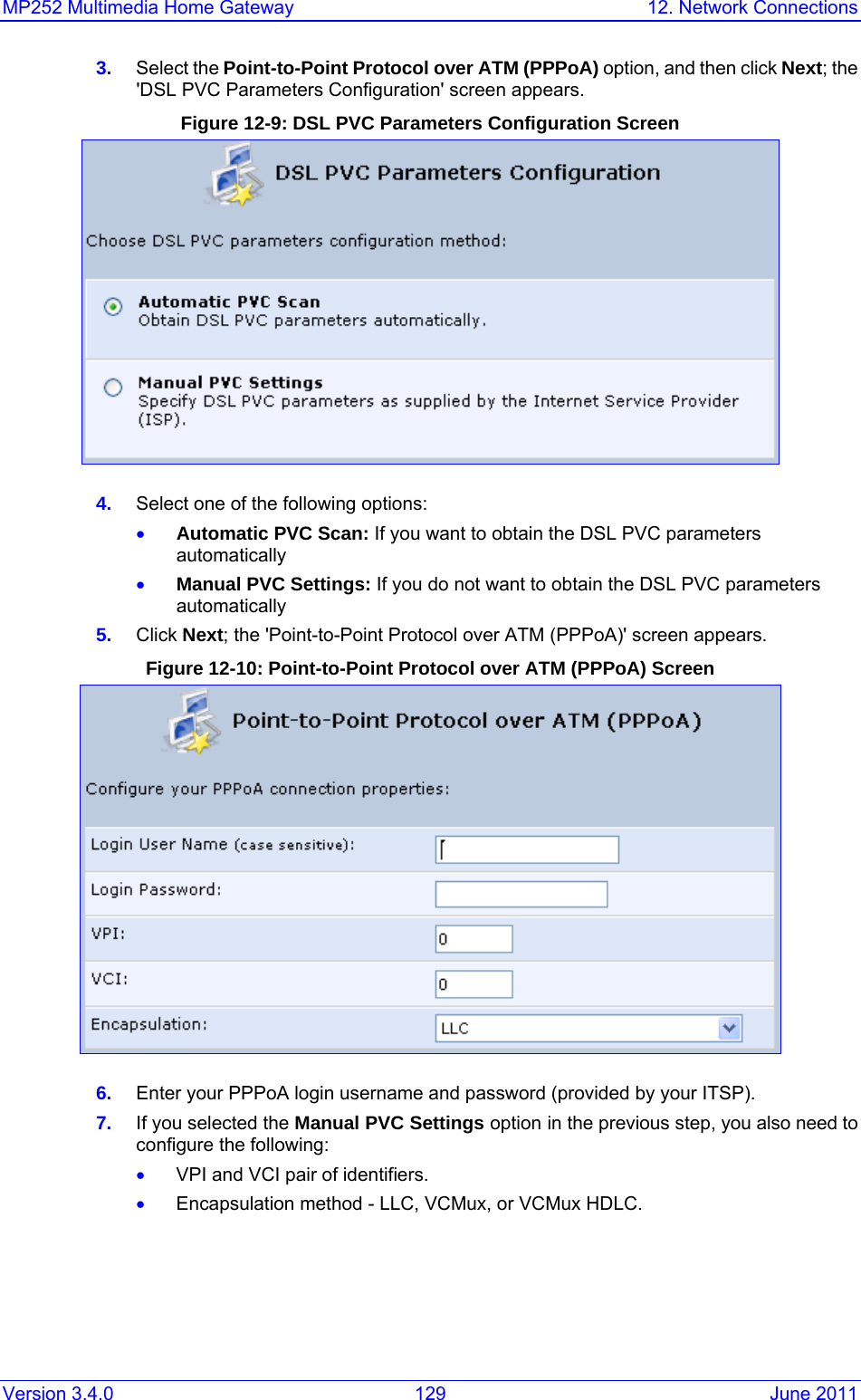
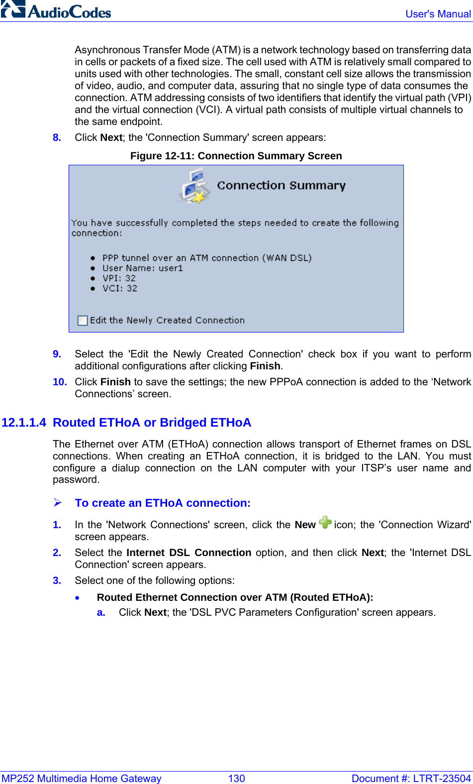
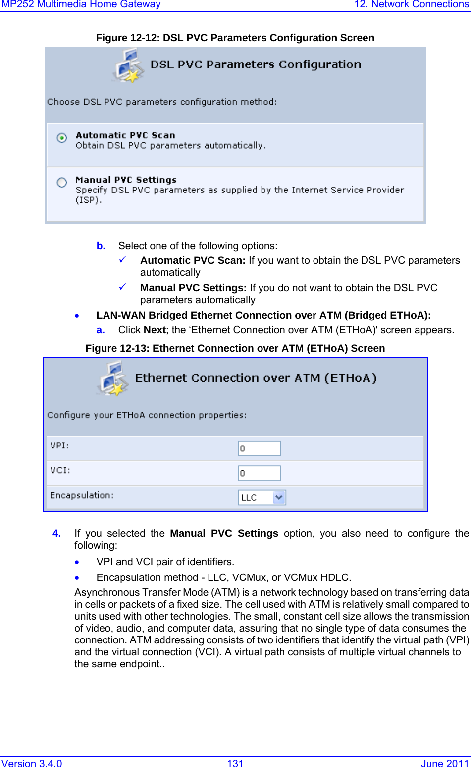
Users manual
Contents
1.
Users manual
2.
manual
3.
users manual
4.
Users Manual
Users manual
Navigation menu
Upload a User Manual
Namespaces
Wiki Guide
HTML
PDF
Info
Views
User Manual
Discussion / Help
Navigation
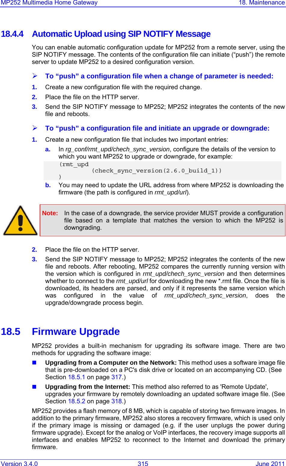
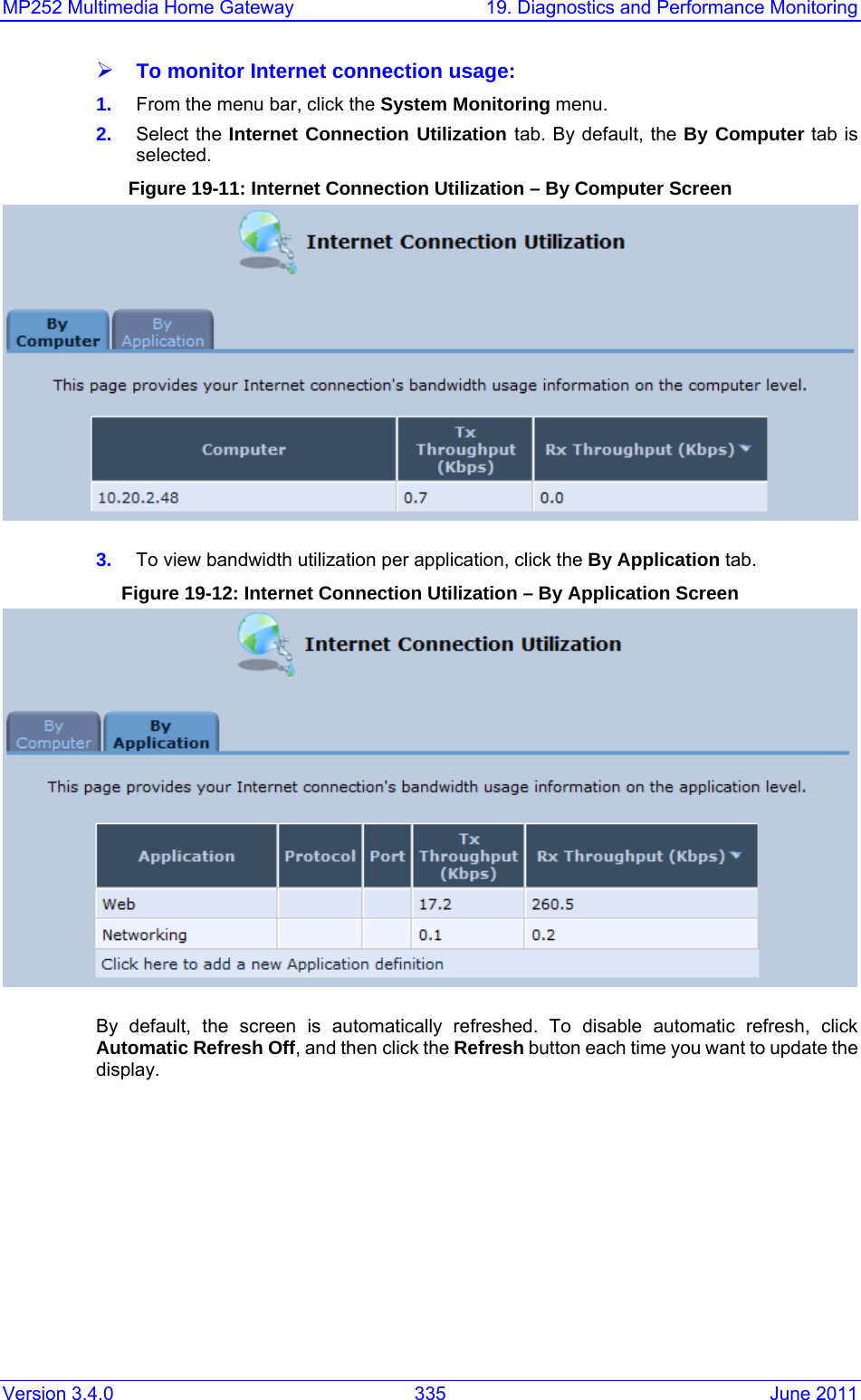
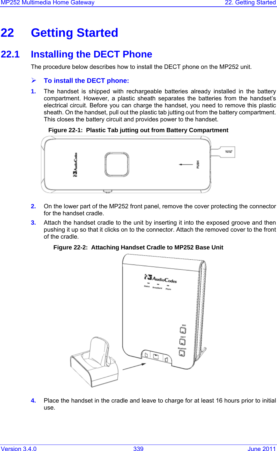
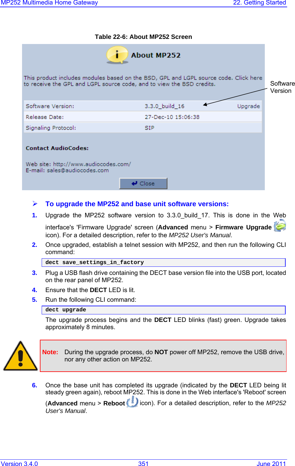
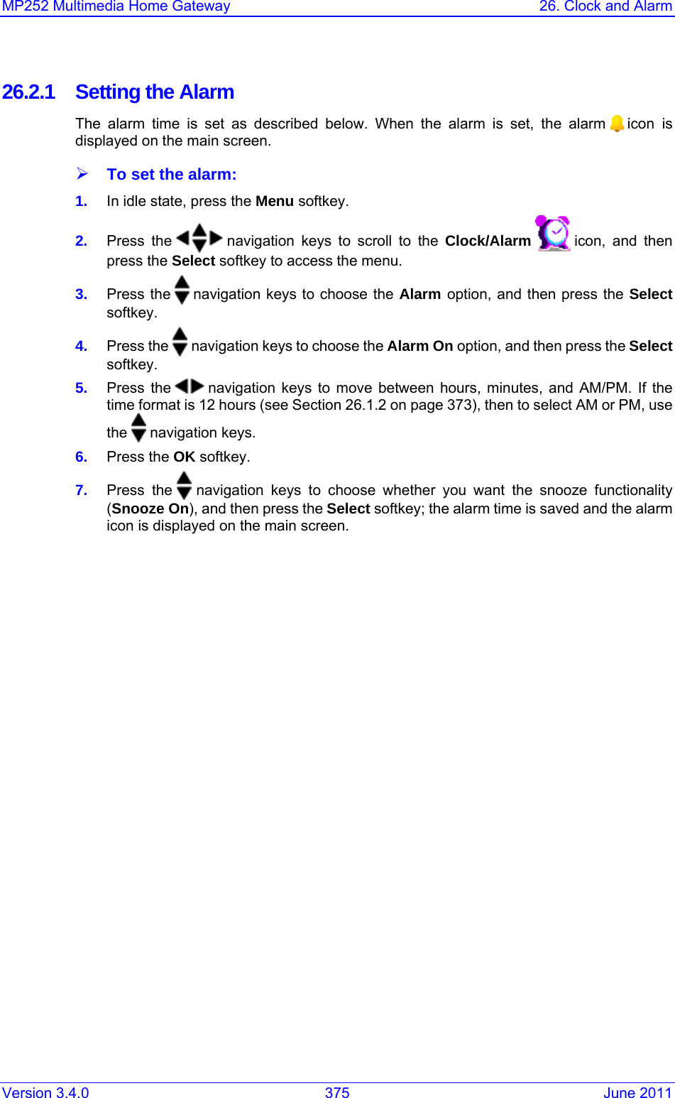
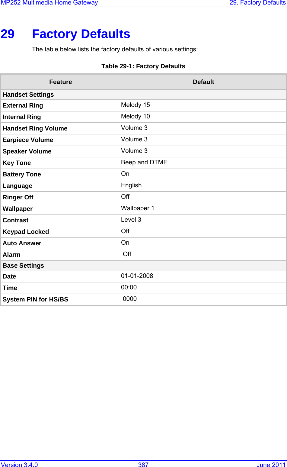
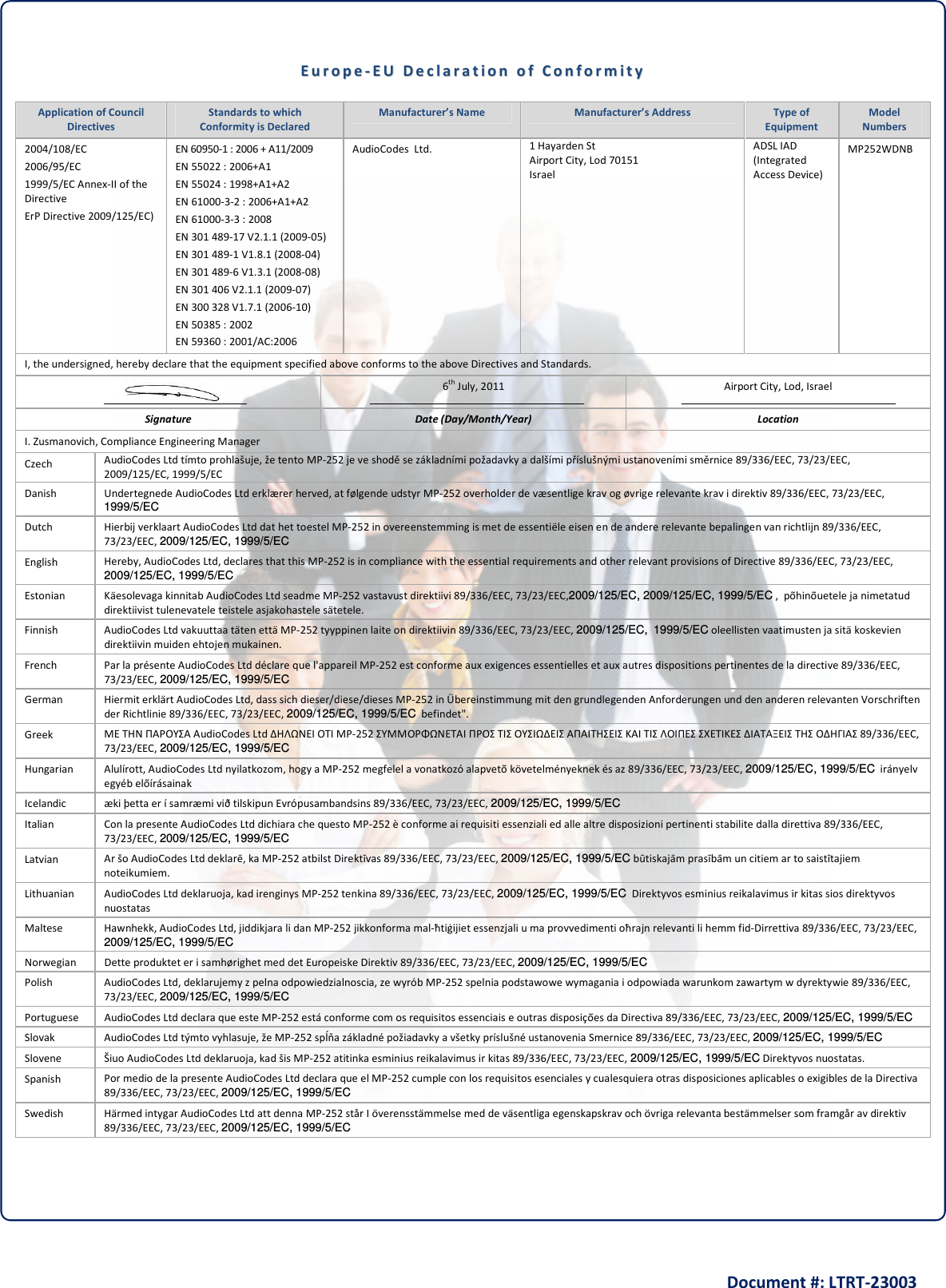
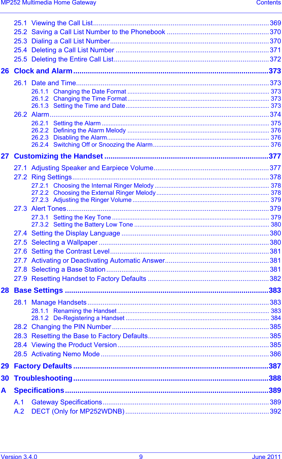
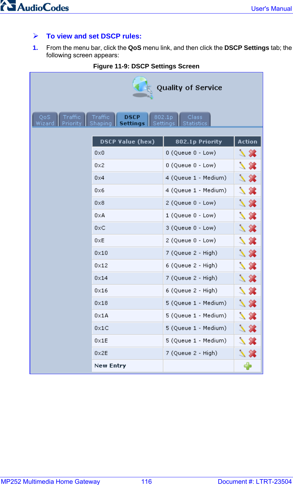
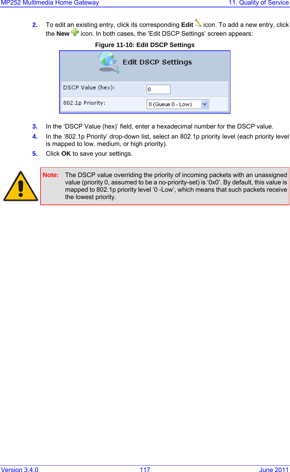
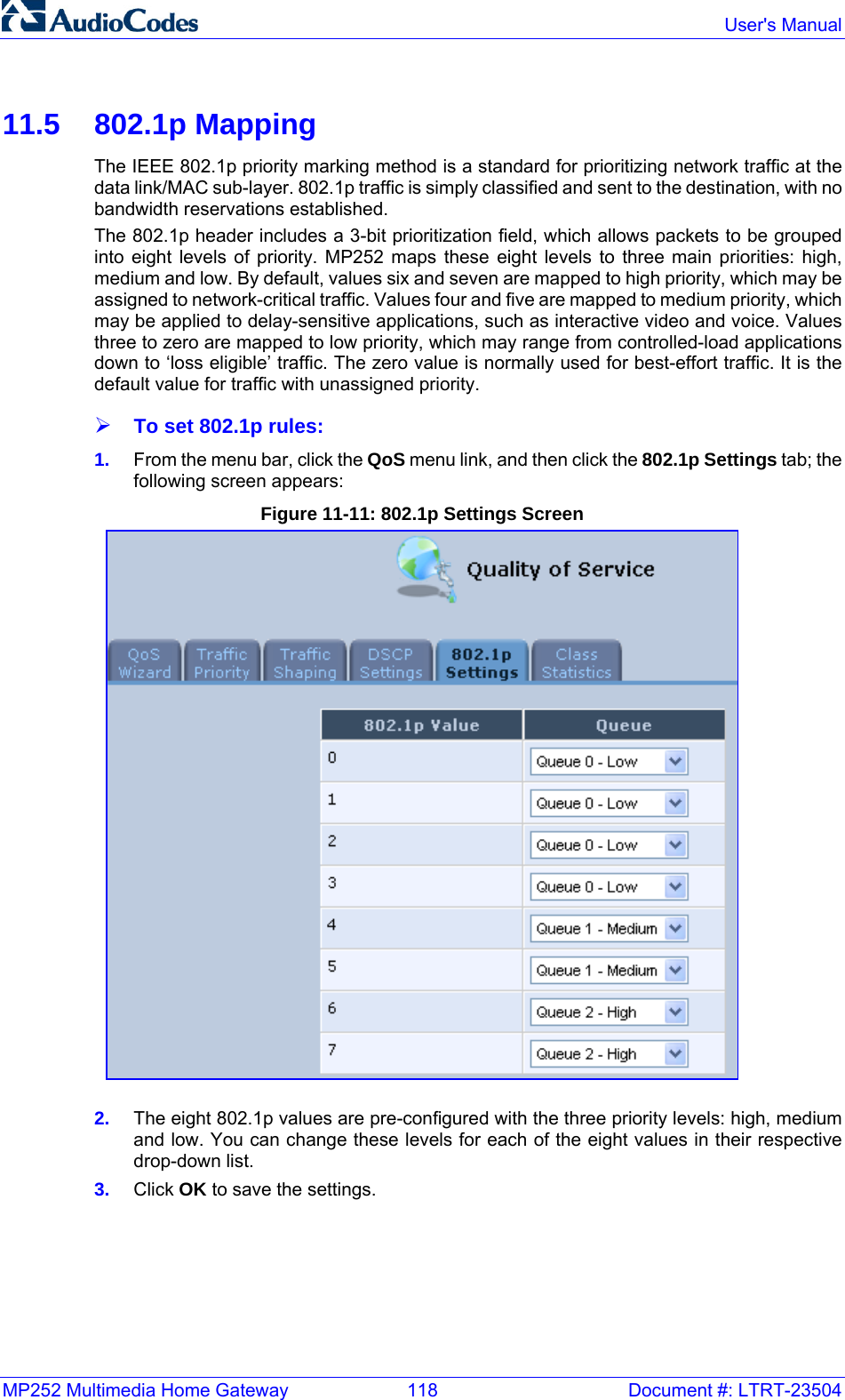
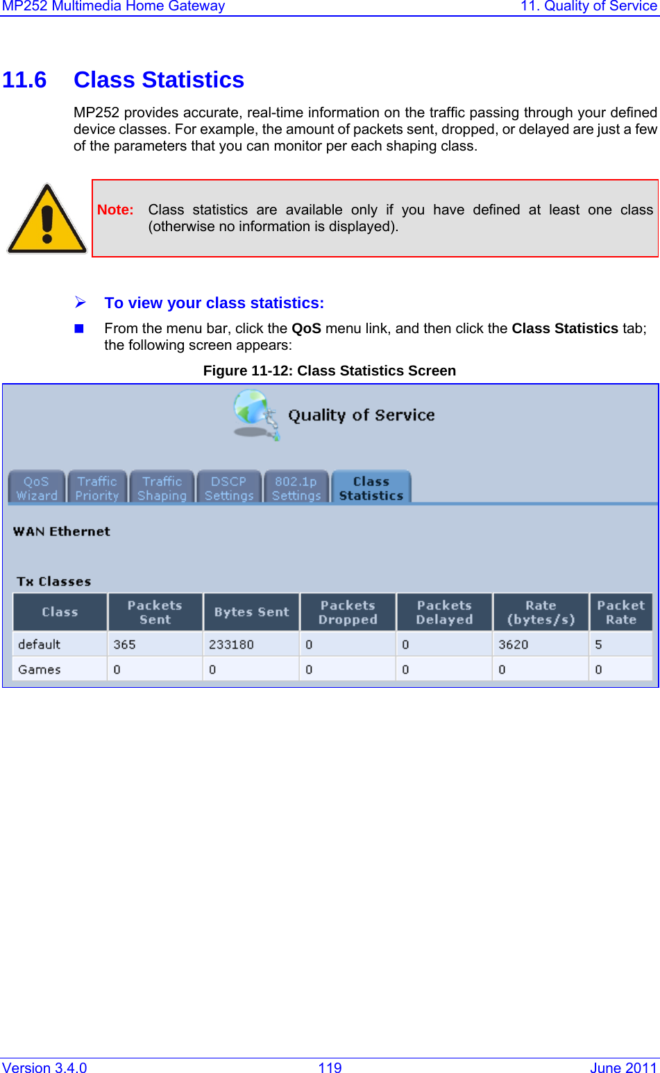
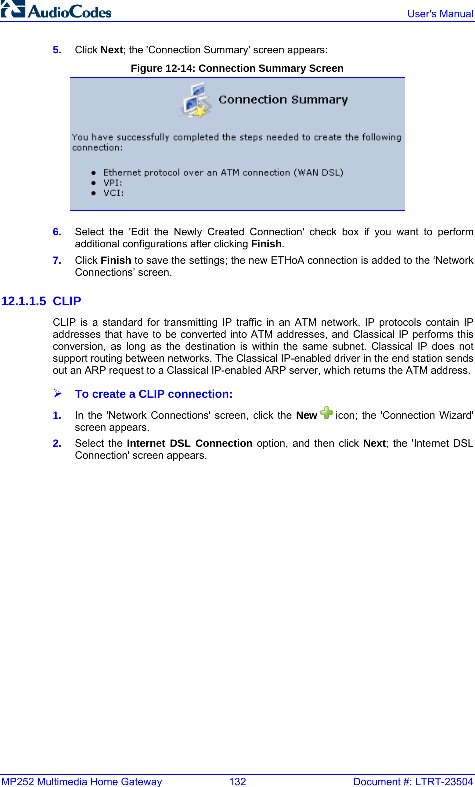
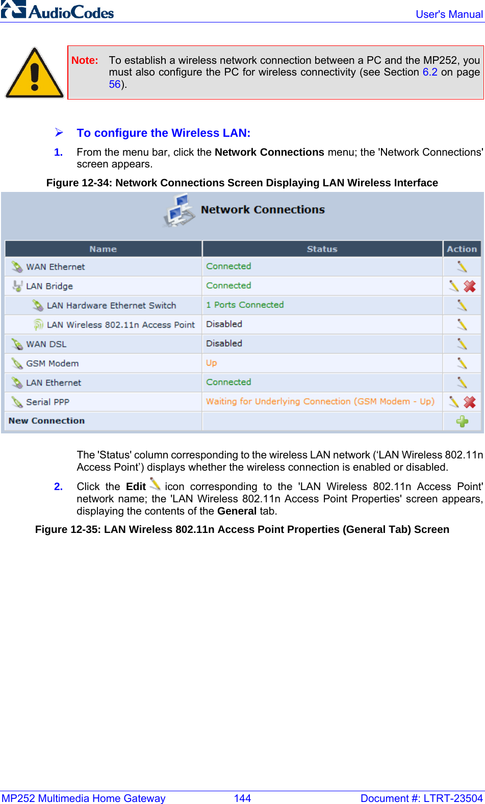
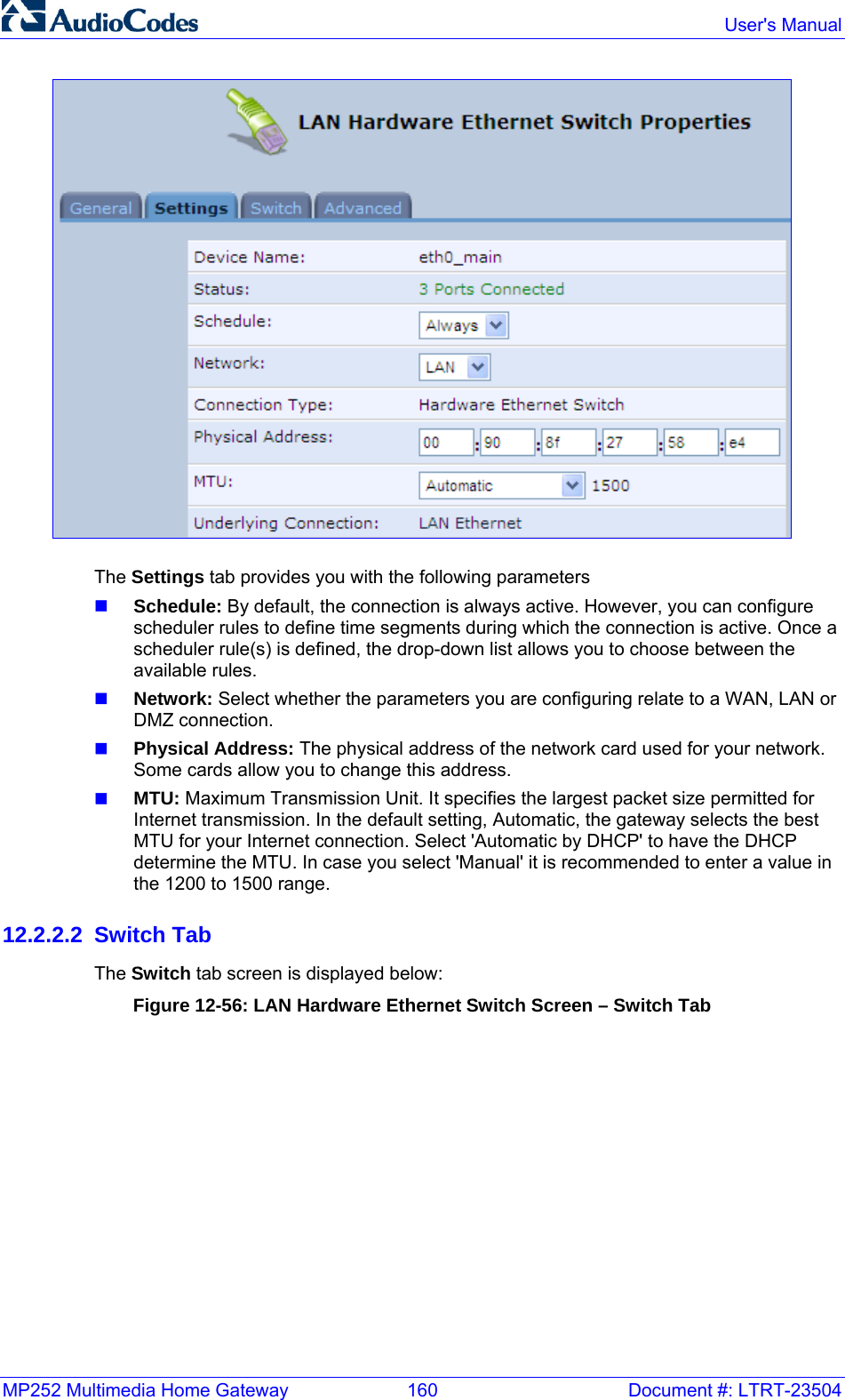
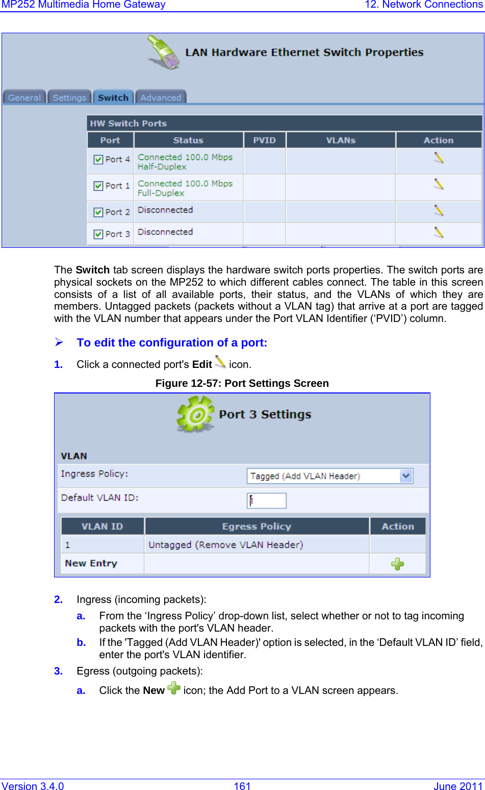
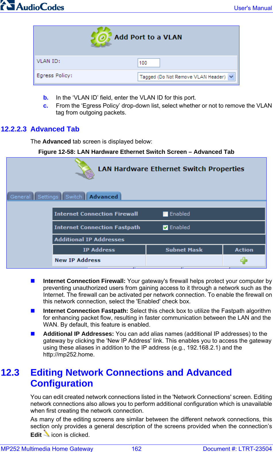
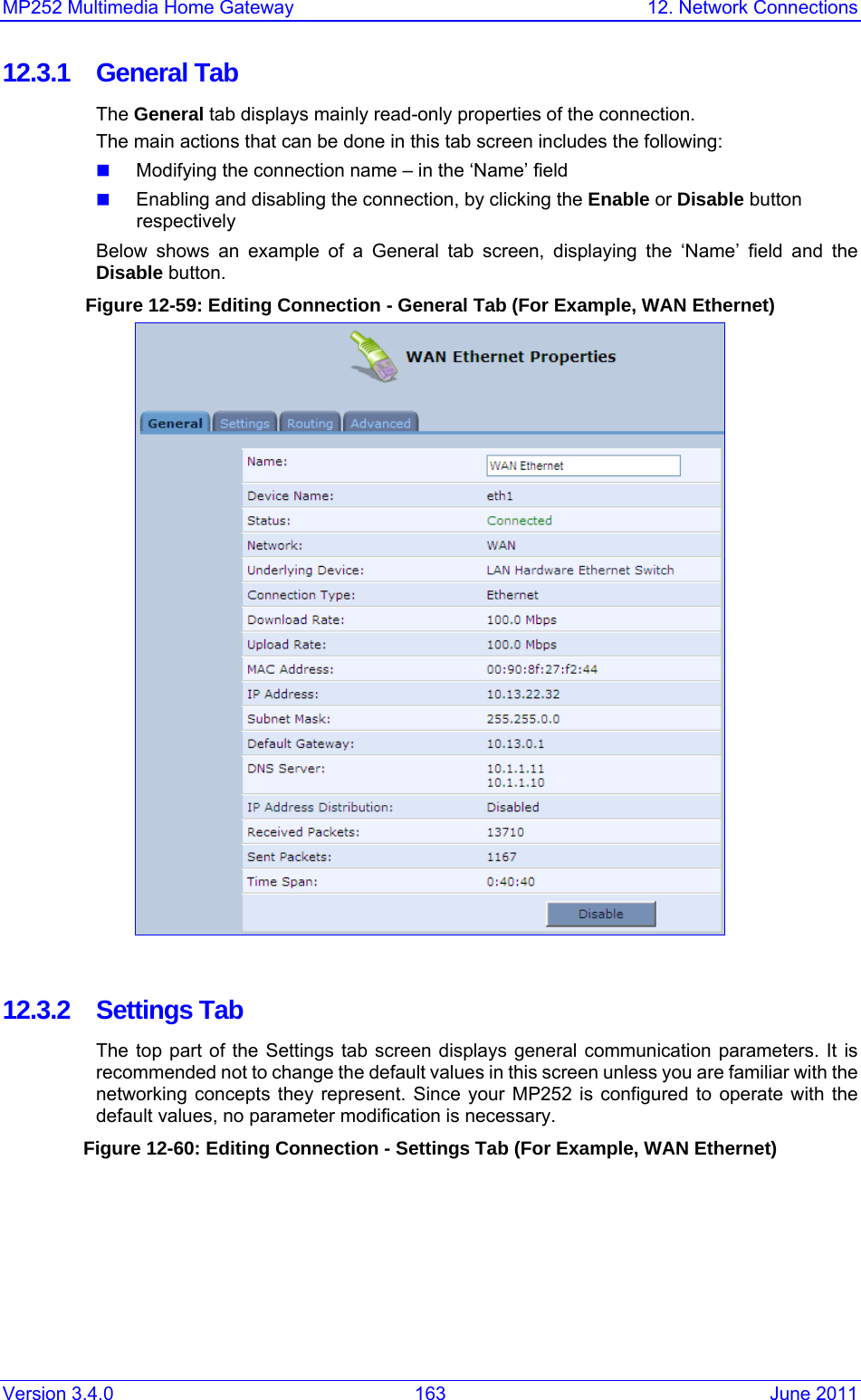
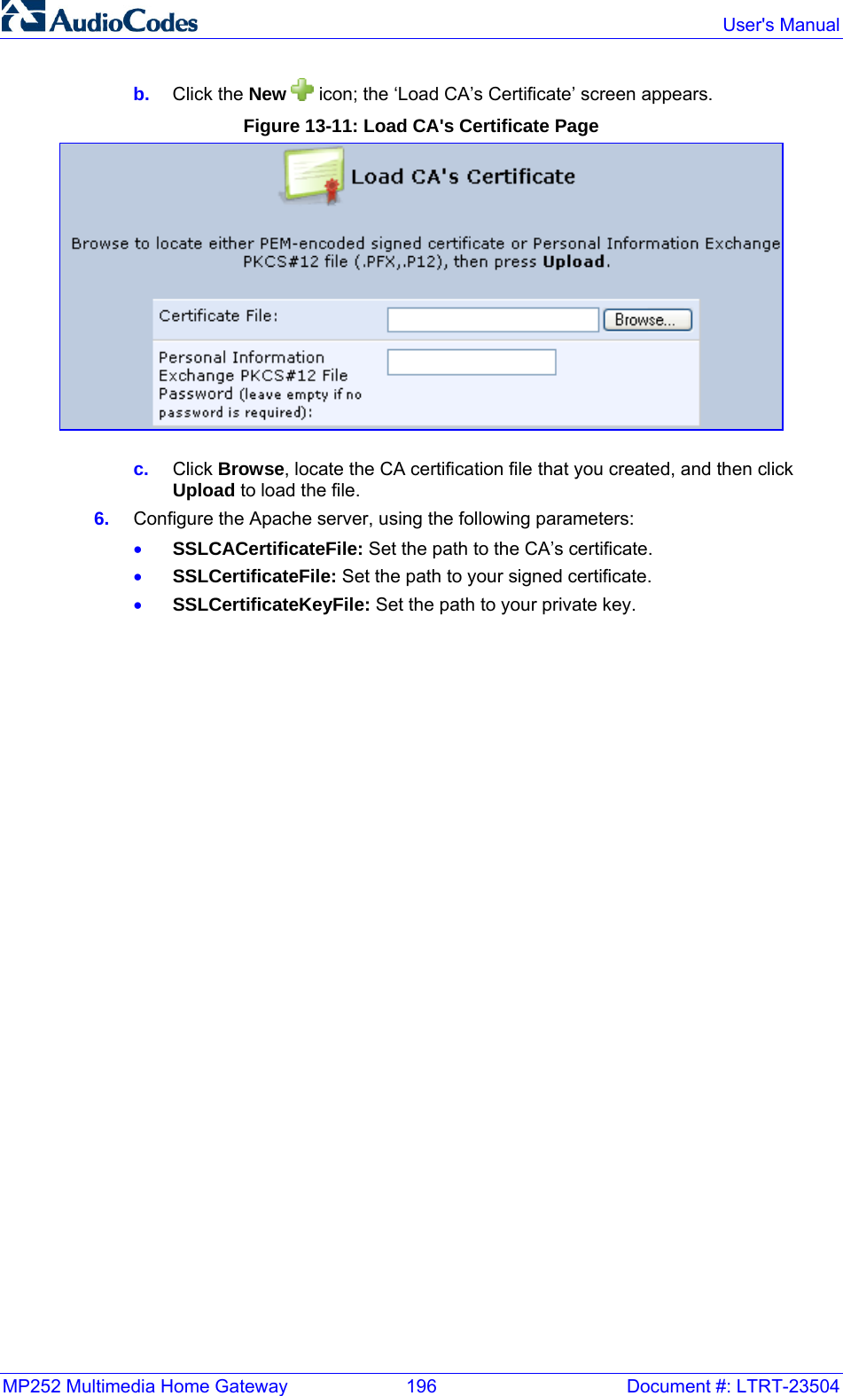
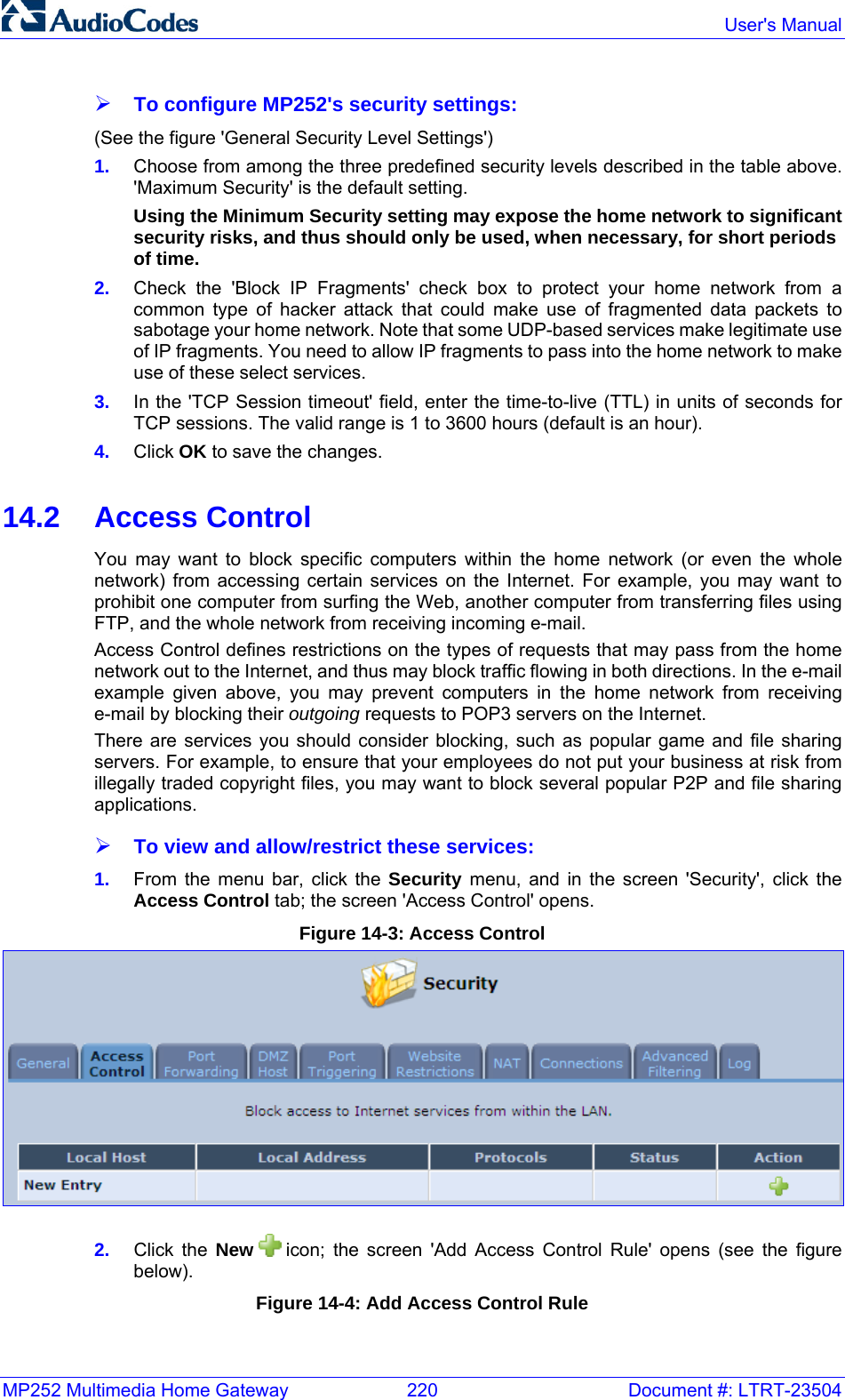
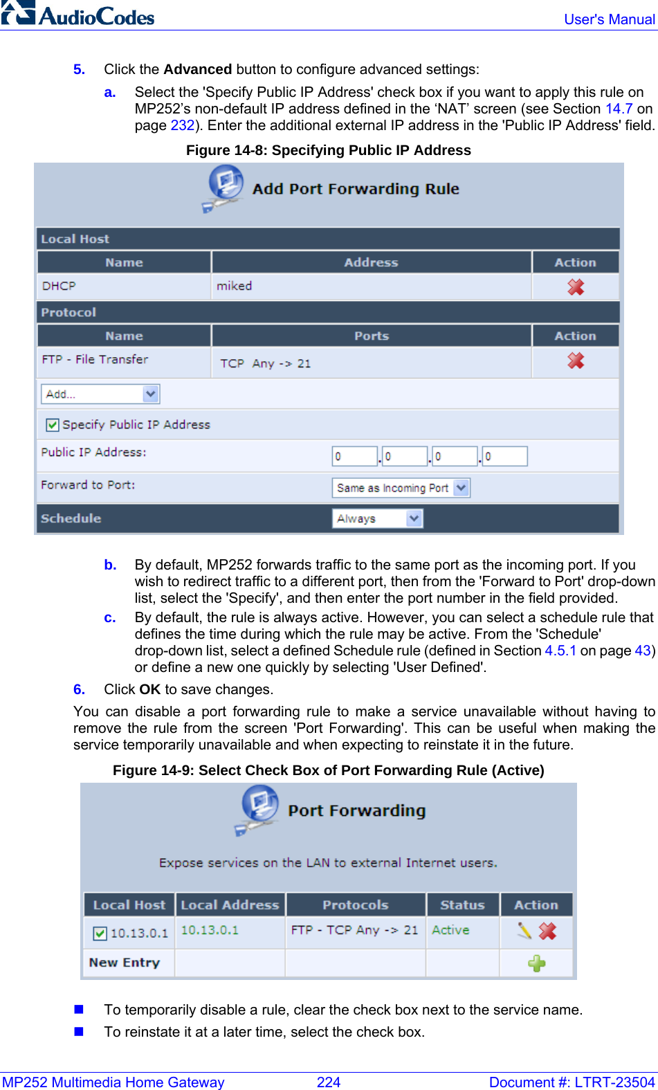
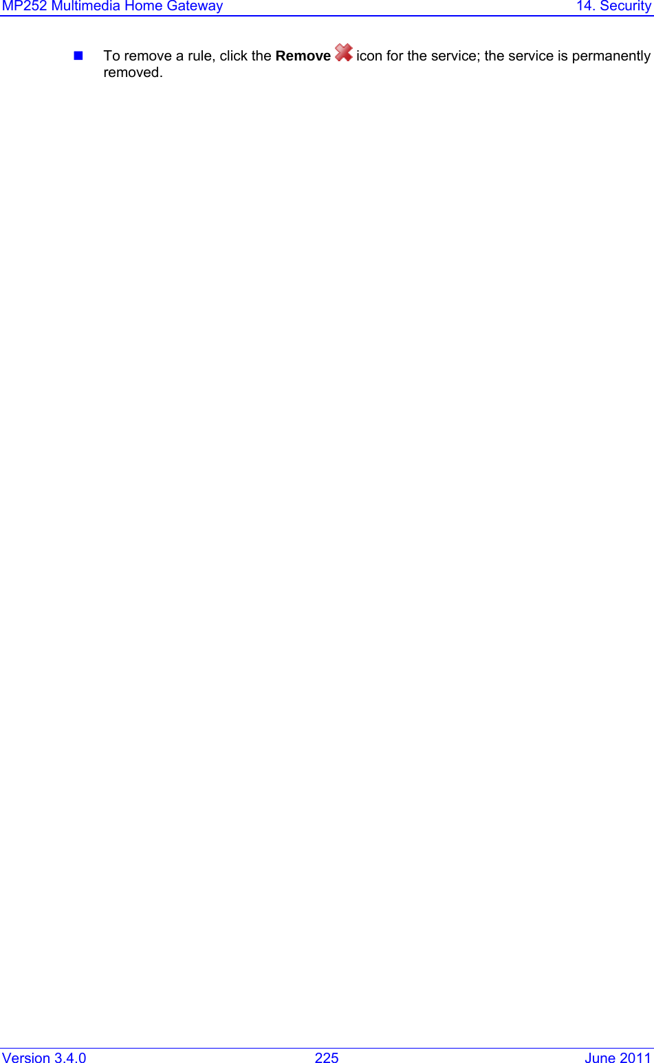
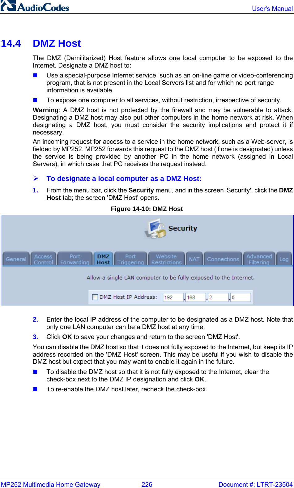
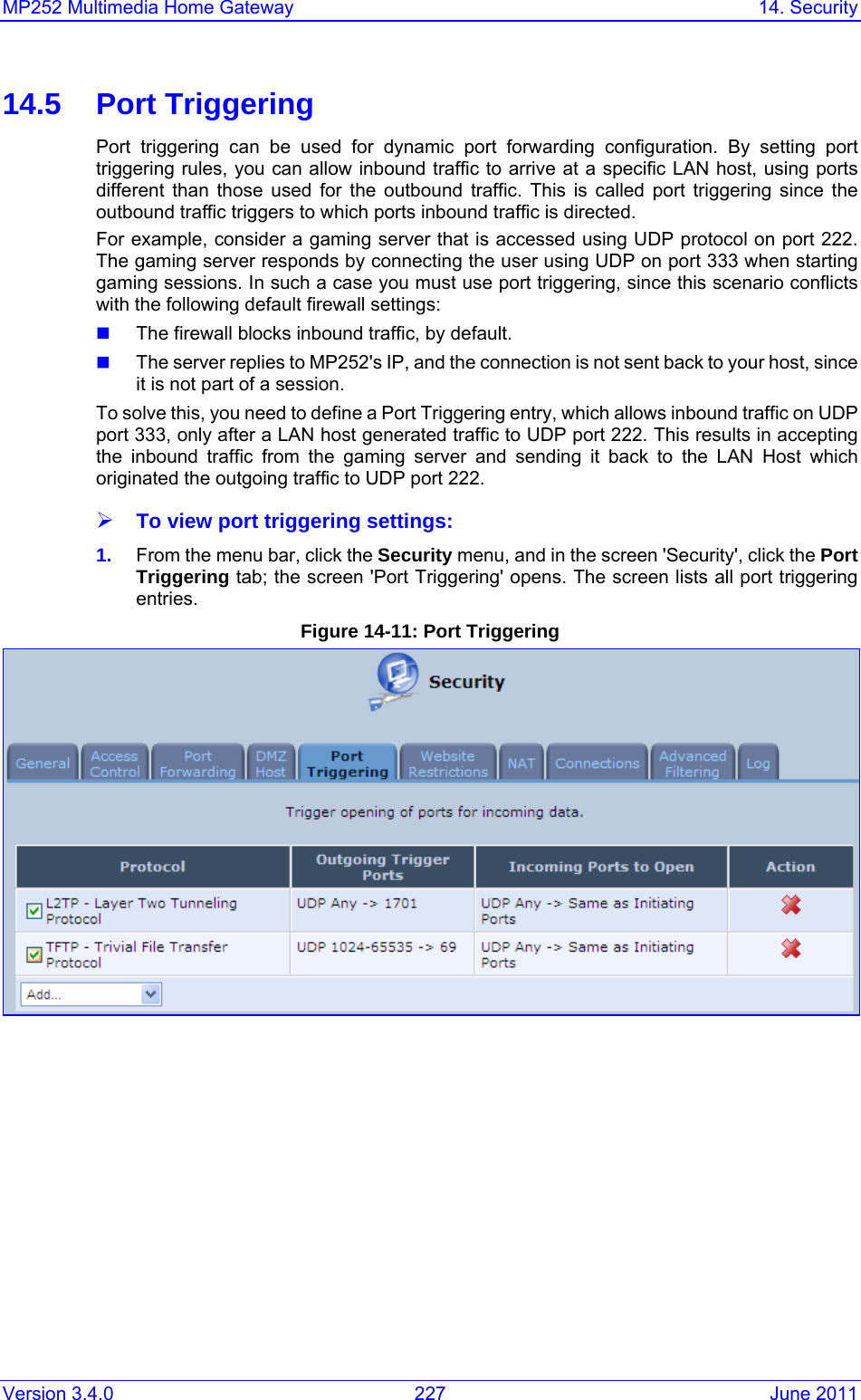
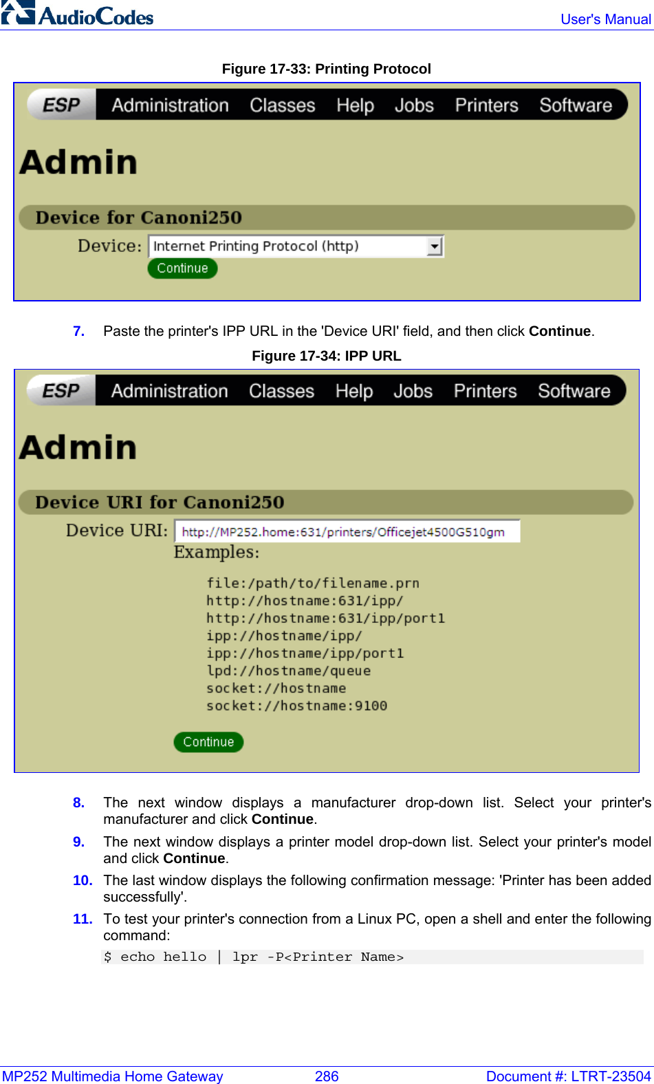
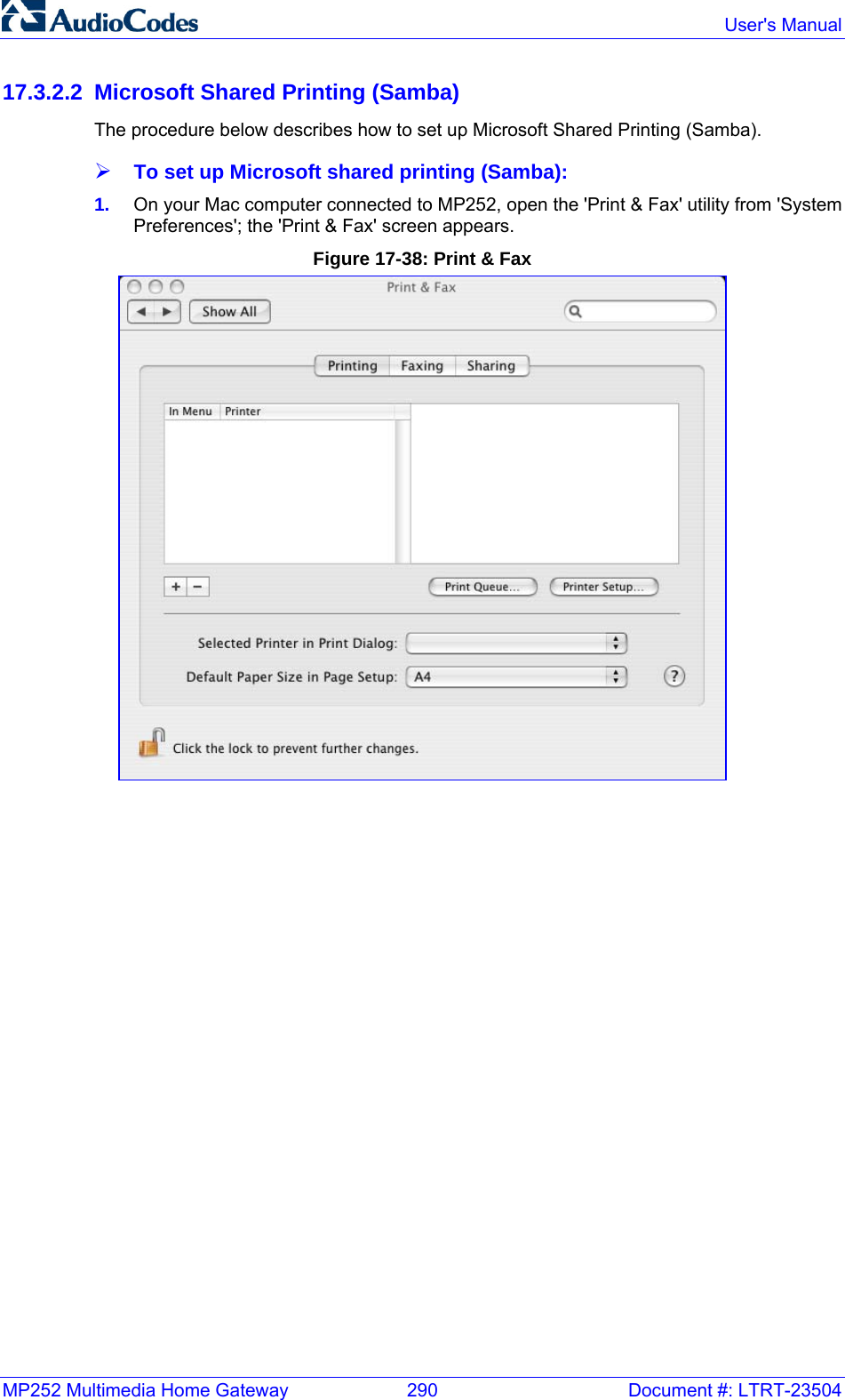
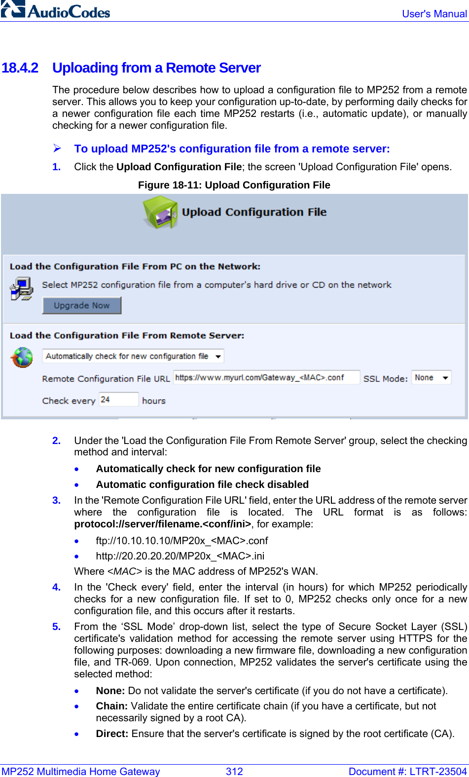
![Important Product Information for MP-252 Series Document #: LTRT-23003 TThhaannkk--yyoouu ffoorr CChhoooossiinngg AAuuddiiooCCooddeess This important product information includes Regulatory and Safety information. Before you start using this product, please read the Safety Instructions provided. These Instructions can also be downloaded from the AudioCodes Website at http://www.audiocodes.com/library. This document, the Installation Manual and User’s Manual (as well as software files and other documentation) can be downloaded from the AudioCodes Website at http://www.audiocodes.com/downloads. Check that all items as listed in the Installation Manual are supplied in the shipped package. If any items are missing or if you have any queries, contact your AudioCodes sales representative. If your product was purchased directly from AudioCodes, then contact support@audiocodes.com. If the product was purchased from AudioCodes’ Distributors, Partners, or Resellers, then use the contact details provided by these sellers. WWaarrnniinngg The device will be inoperable when the mains power fails and the battery backup is not connected. IInndduussttrryy CCaannaaddaa NNoottiiccee This equipment meets the applicable Industry Canada Terminal Equipment technical specifications. This is confirmed by the registration numbers. The abbreviation, IC, before the registration number signifies that registration was performed based on a declaration of conformity indicating that Industry Canada technical specifications were met. It does not imply that Industry Canada approved the equipment. FFoorr CCuussttoommeerrss iinn CCaannaaddaa This Class [B] digital apparatus complies with Canadian ICES-003. Cet appareil numérique de la classe [B] est conforme à la norme NMB-003 du Canada. Operation is subject to the following two conditions: (1) this device may not cause interference, and (2) this device must accept any interference, including interference that may cause undesired operation of the device. This device and its antenna(s) must not be co-located or operating in conjunction with any other antenna or transmitter. The County Code Selection feature is disabled for products marketed in the US/Canada. IICC RRaaddiiaattiioonn EExxppoossuurree SSttaatteemmeenntt This equipment complies with IC RSS-102 radiation exposure limits set forth for an uncontrolled environment. This equipment should be installed and operated with minimum distance of 20 cm between the radiator and your body. SSaaffeettyy NNoottiiccee 1. To avoid risk of fire, use 26 AWG or higher wiring to connect the FXO, ADSL telecom ports. 2. Disconnect TNV circuit connector before removing cover. 3. Unit must be powered only by power limited Class 2 certified power adapter Ports Safety Status Ethernet (100Base-TX) SELV FXS TNV-2 FXO, ADSL TNV-3](https://usermanual.wiki/VTech-Telecommunications/80-7597-00.Users-manual/User-Guide-1504581-Page-1.png)
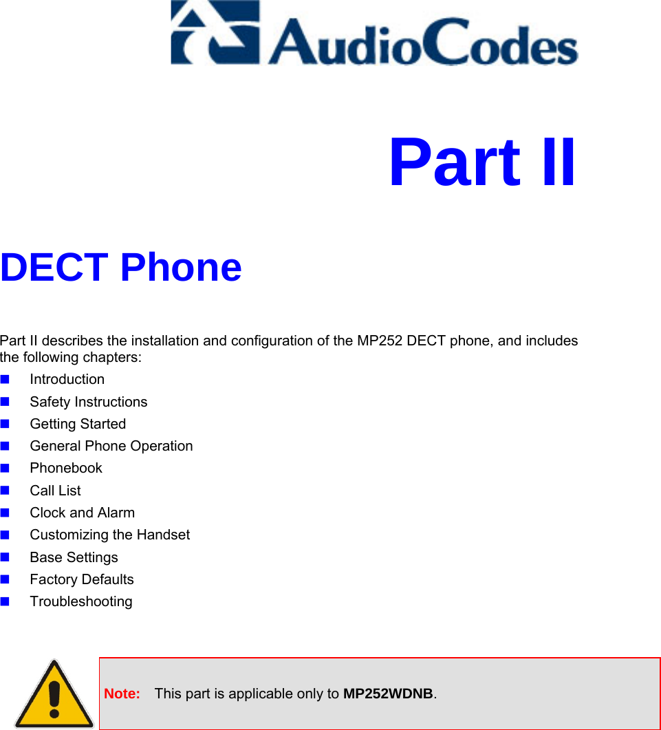
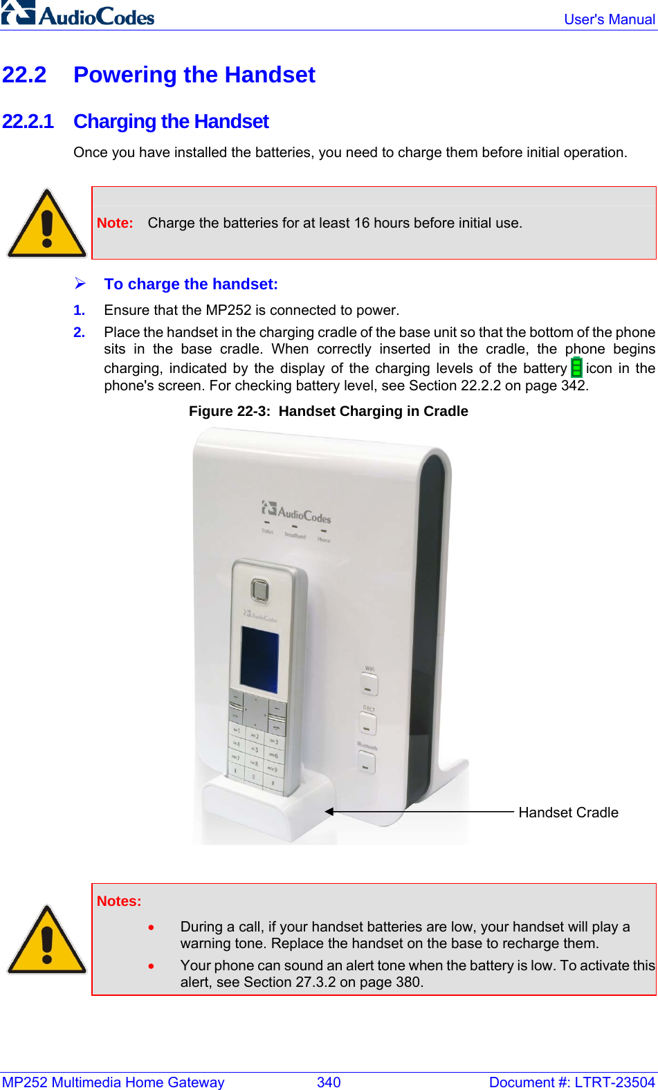
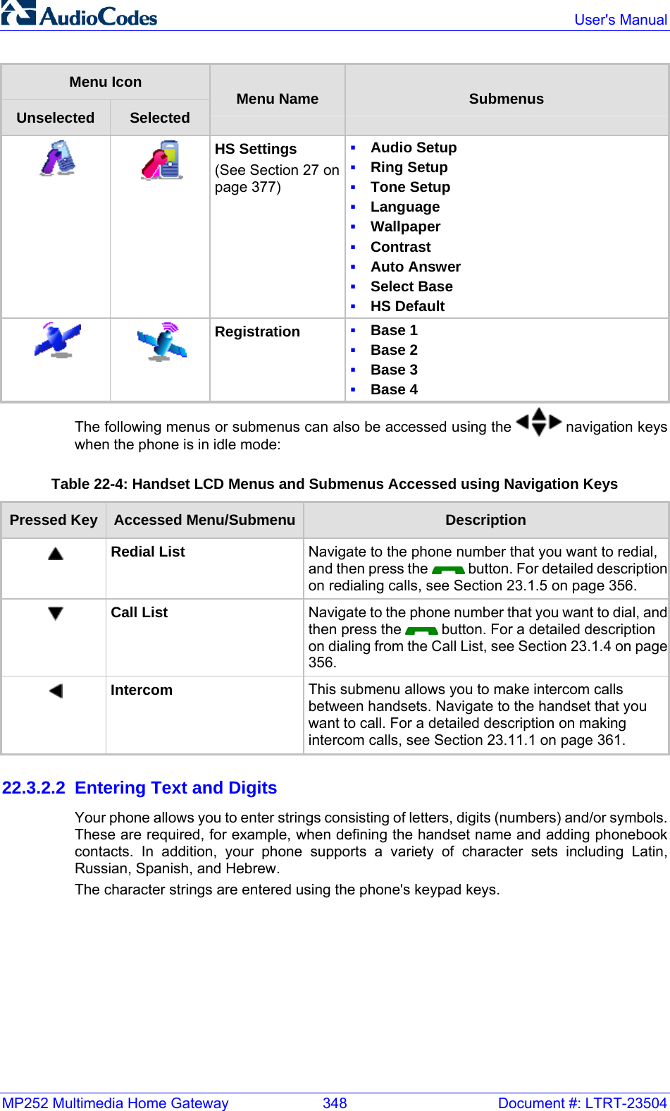
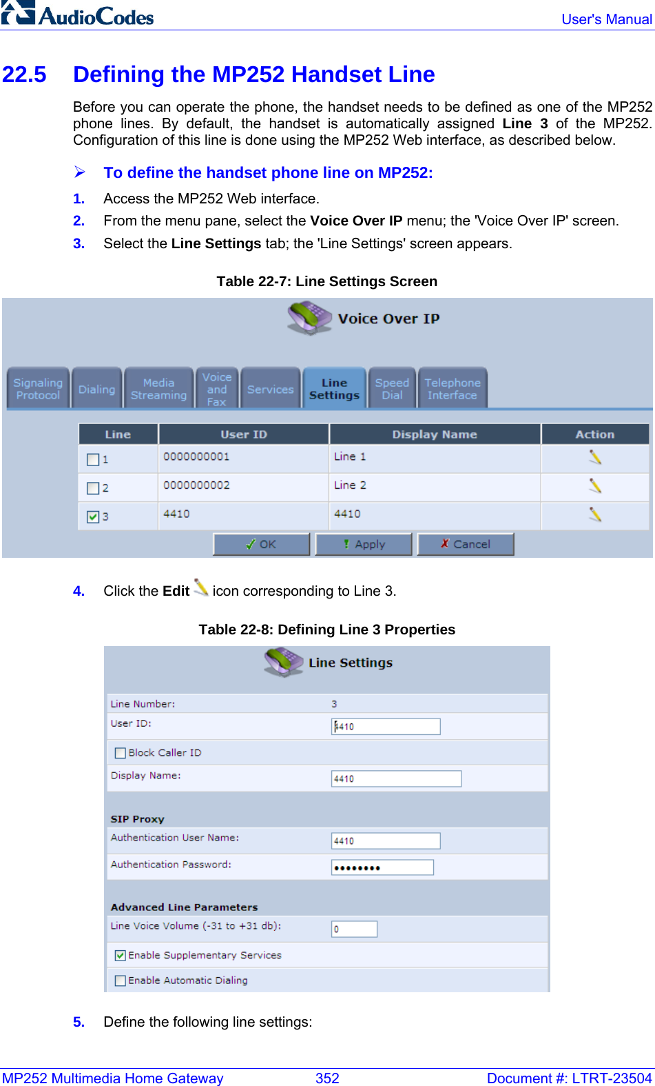
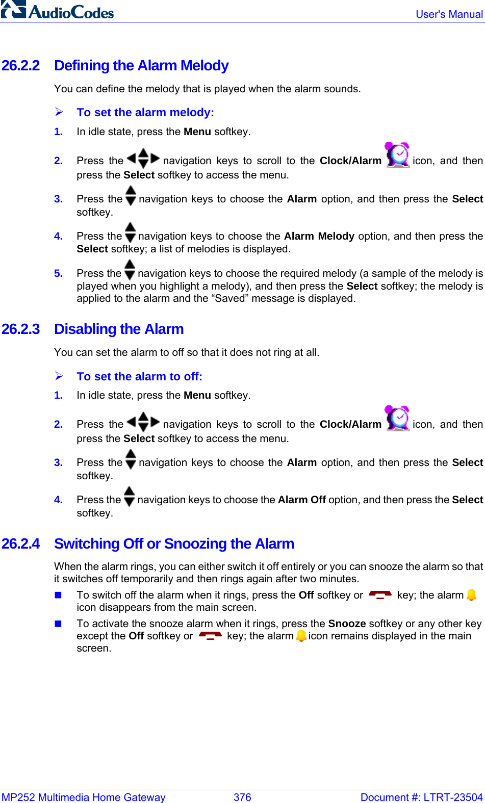
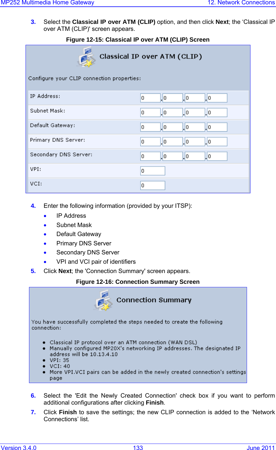
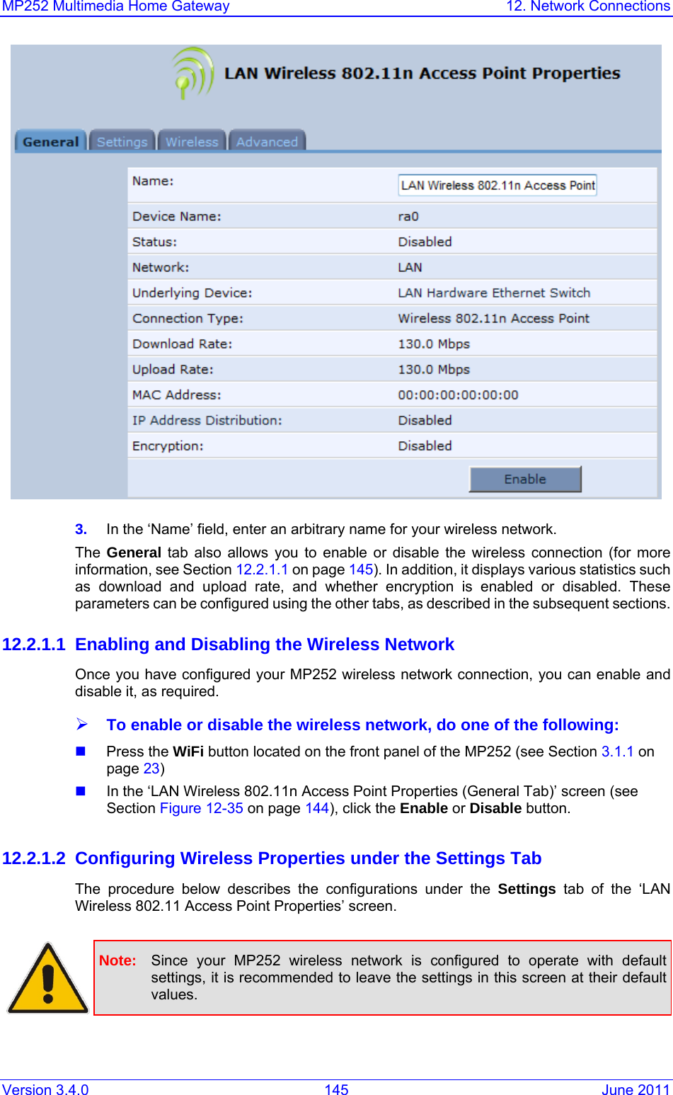
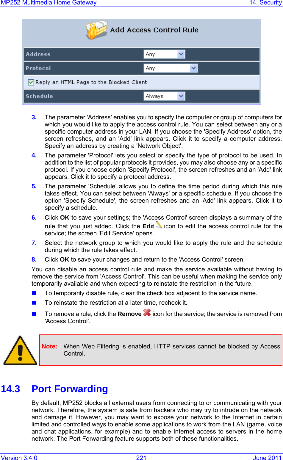
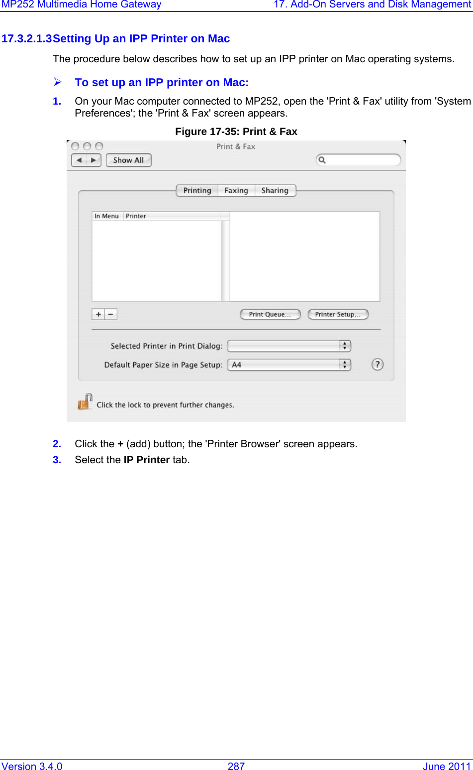
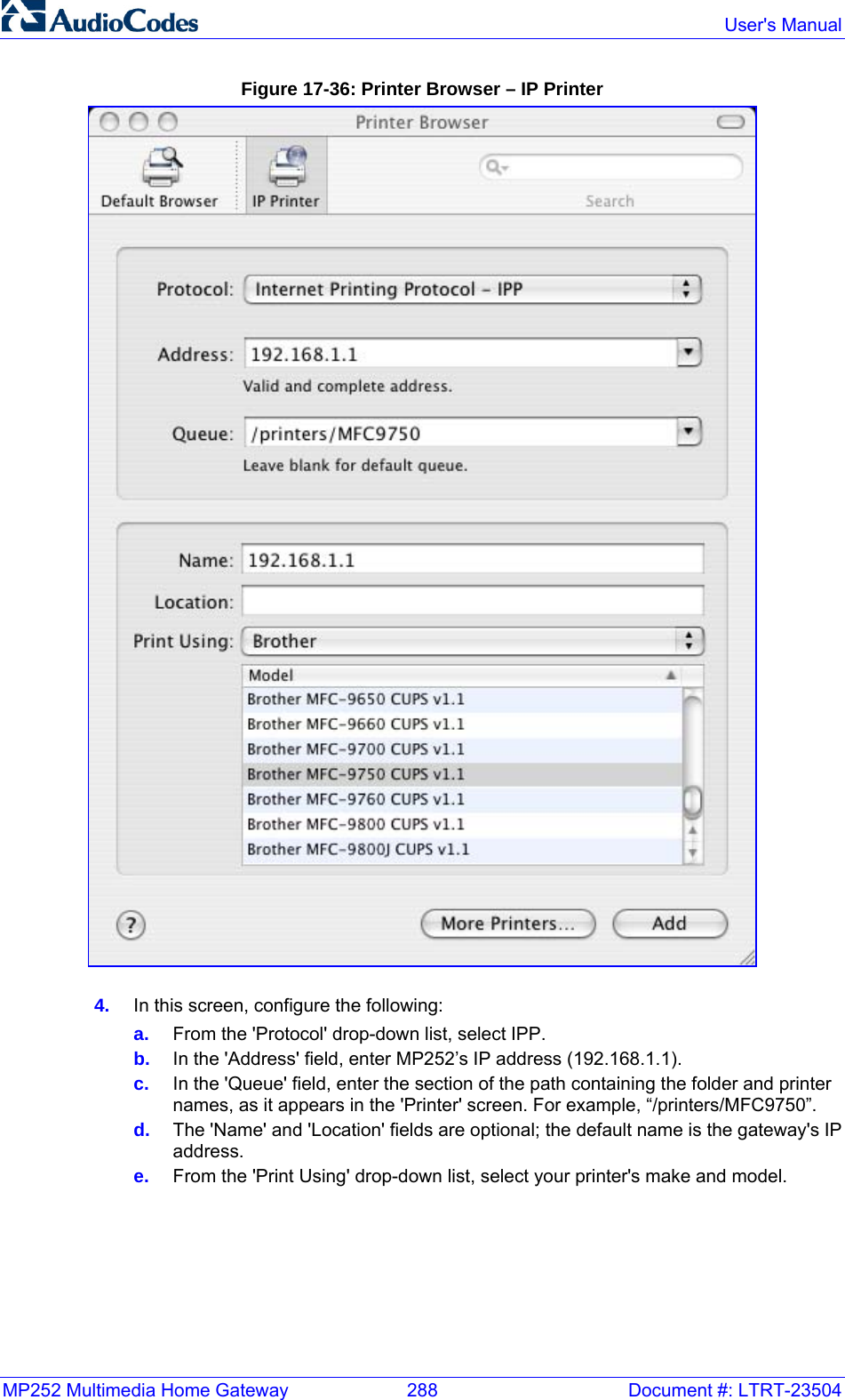
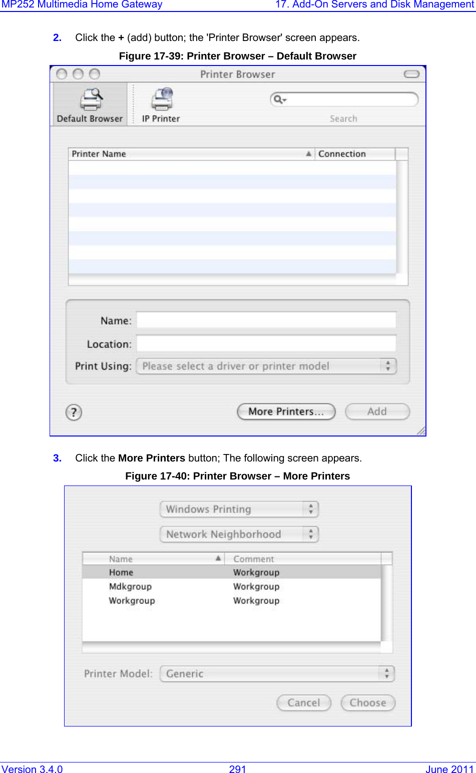
![MP252 Multimedia Home Gateway 1. Introduction Version 3.4.0 19 June 2011 For Customers in Canada This Class [B] digital apparatus complies with Canadian ICES-003. Cet appareil numérique de la classe [B] est conforme à la norme NMB-003 du Canada. Operation is subject to the following two conditions: (1) this device may not cause interference, and (2) this device must accept any interference, including interference that may cause undesired operation of the device. This device and its antenna(s) must not be co-located or operating in conjunction with any other antenna or transmitter. The County Code Selection feature is disabled for products marketed in the US/Canada. IC Radiation Exposure Statement This equipment complies with IC RSS-102 radiation exposure limits set forth for an uncontrolled environment. This equipment should be installed and operated with minimum distance of 20 cm between the radiator and your body.](https://usermanual.wiki/VTech-Telecommunications/80-7597-00.Users-manual/User-Guide-1504581-Page-23.png)
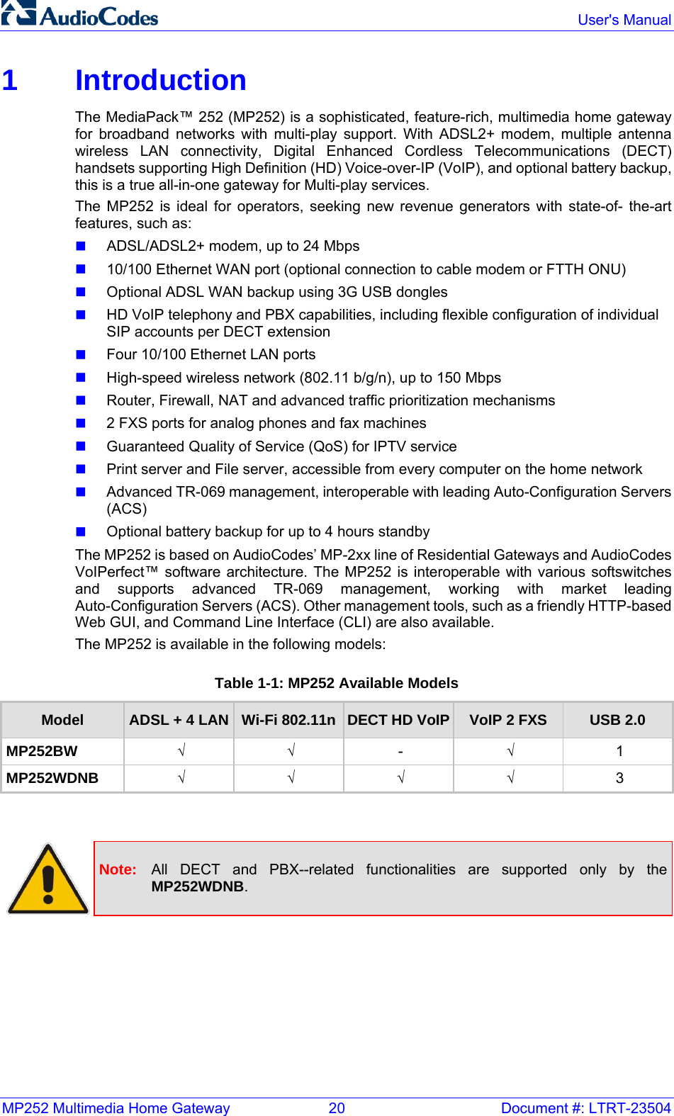
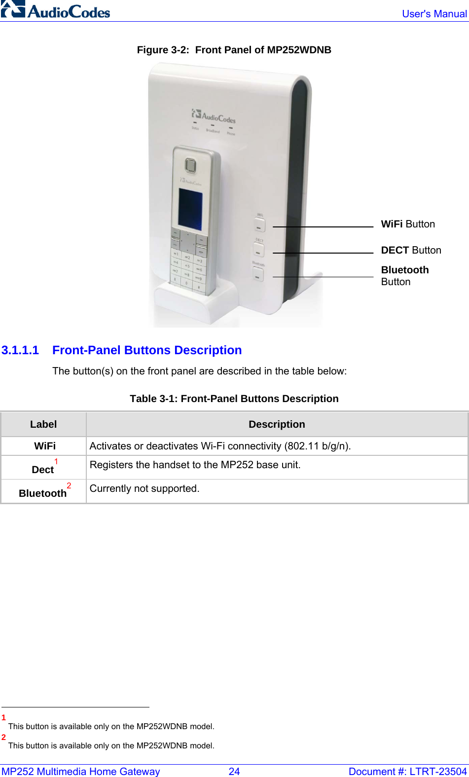
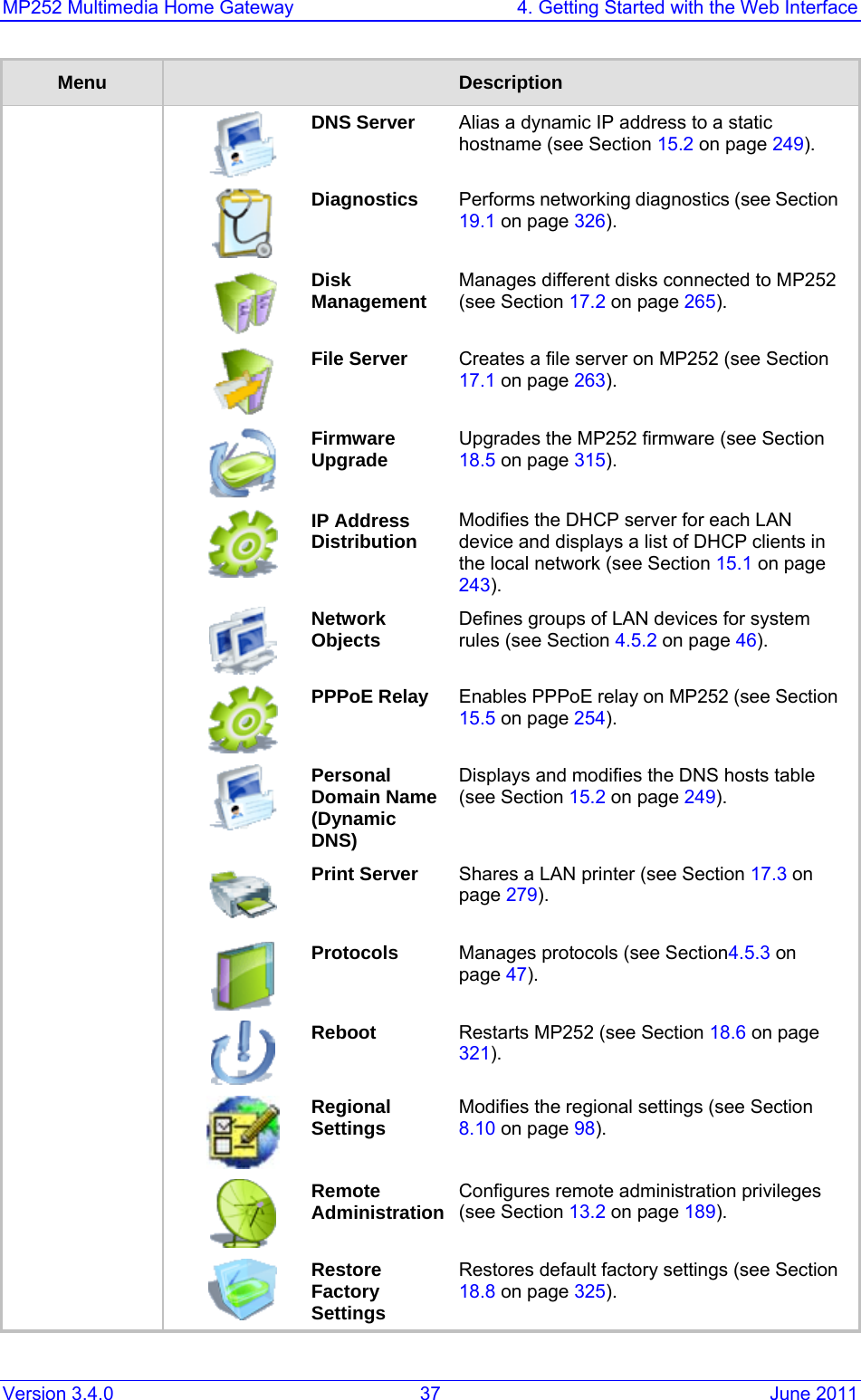
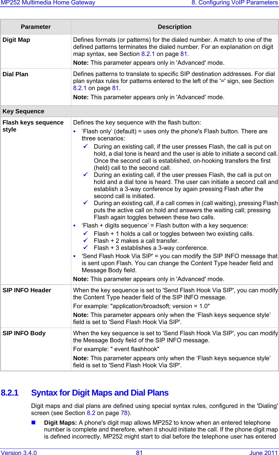
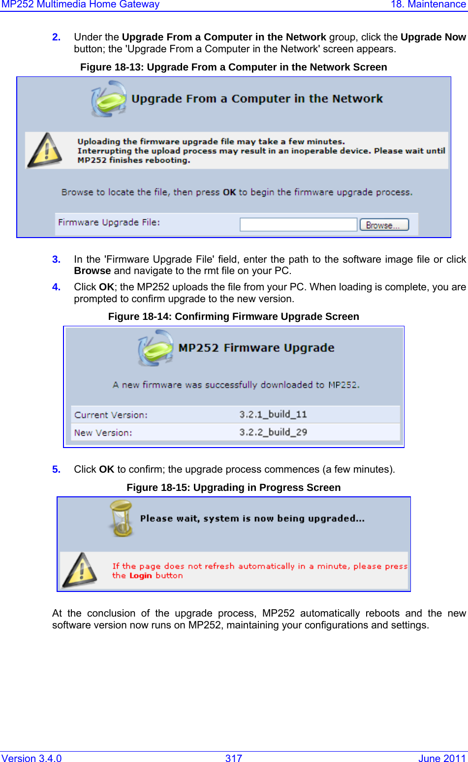
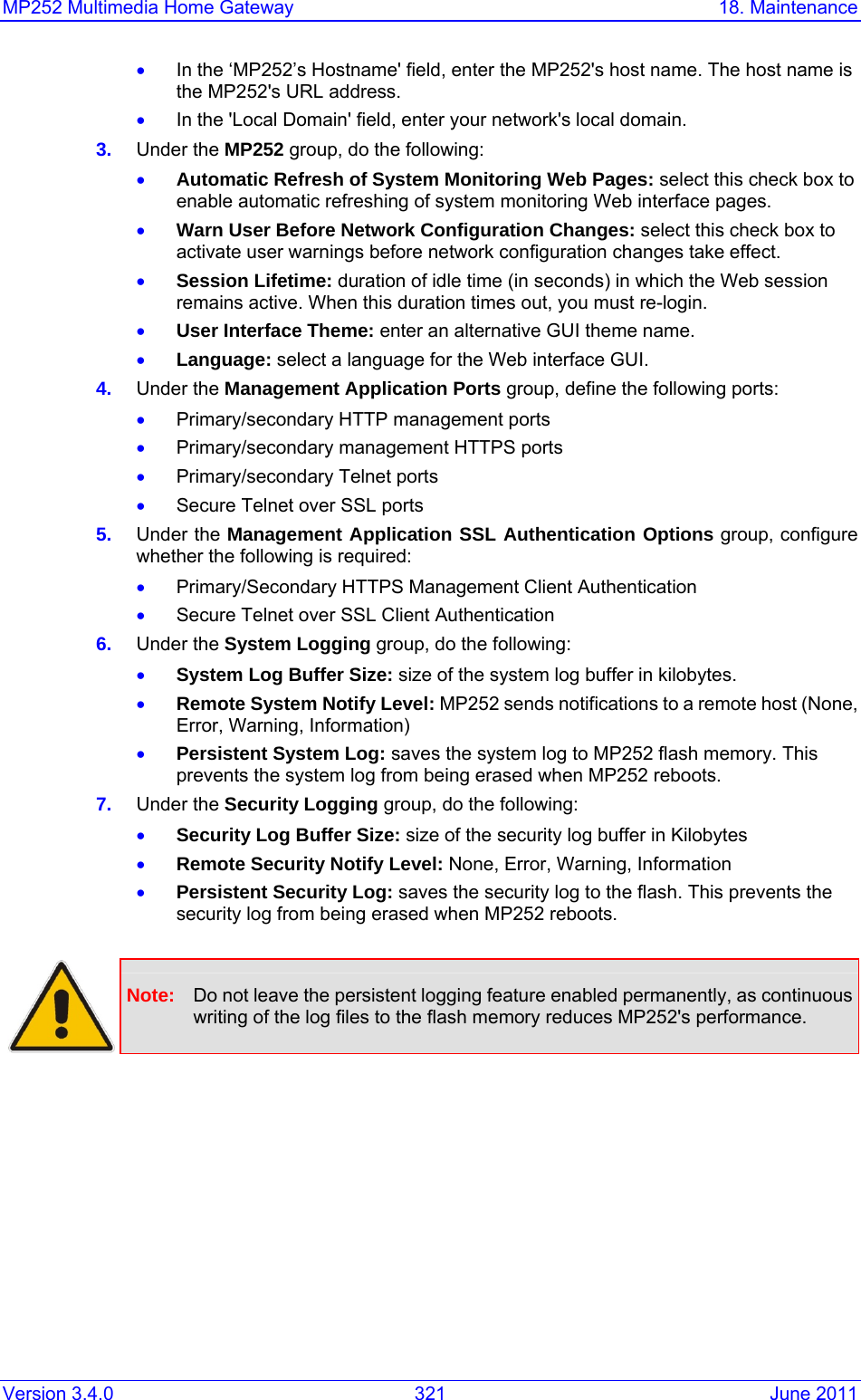
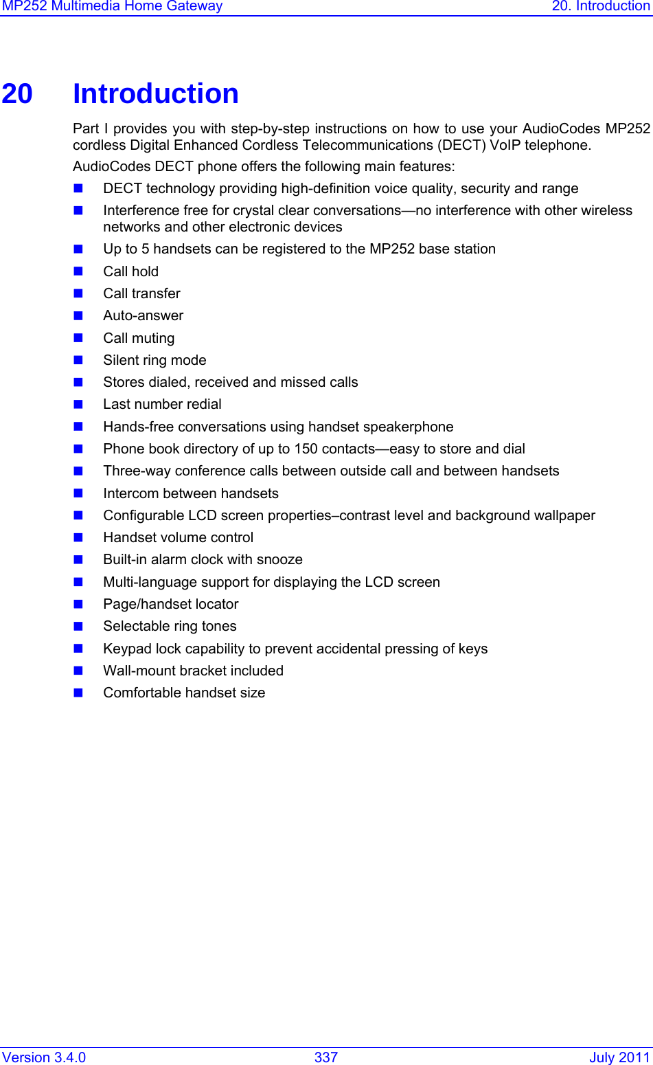
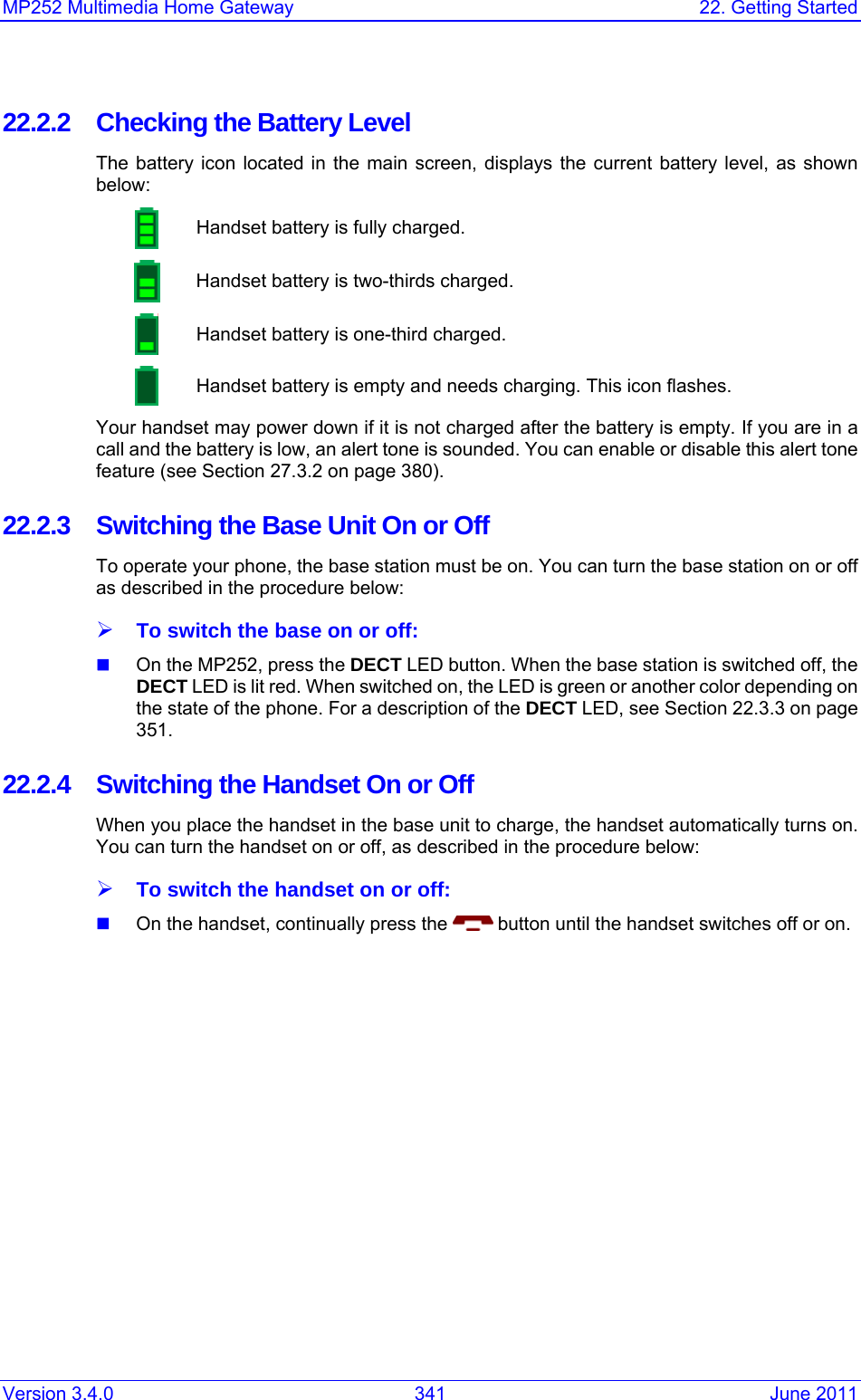
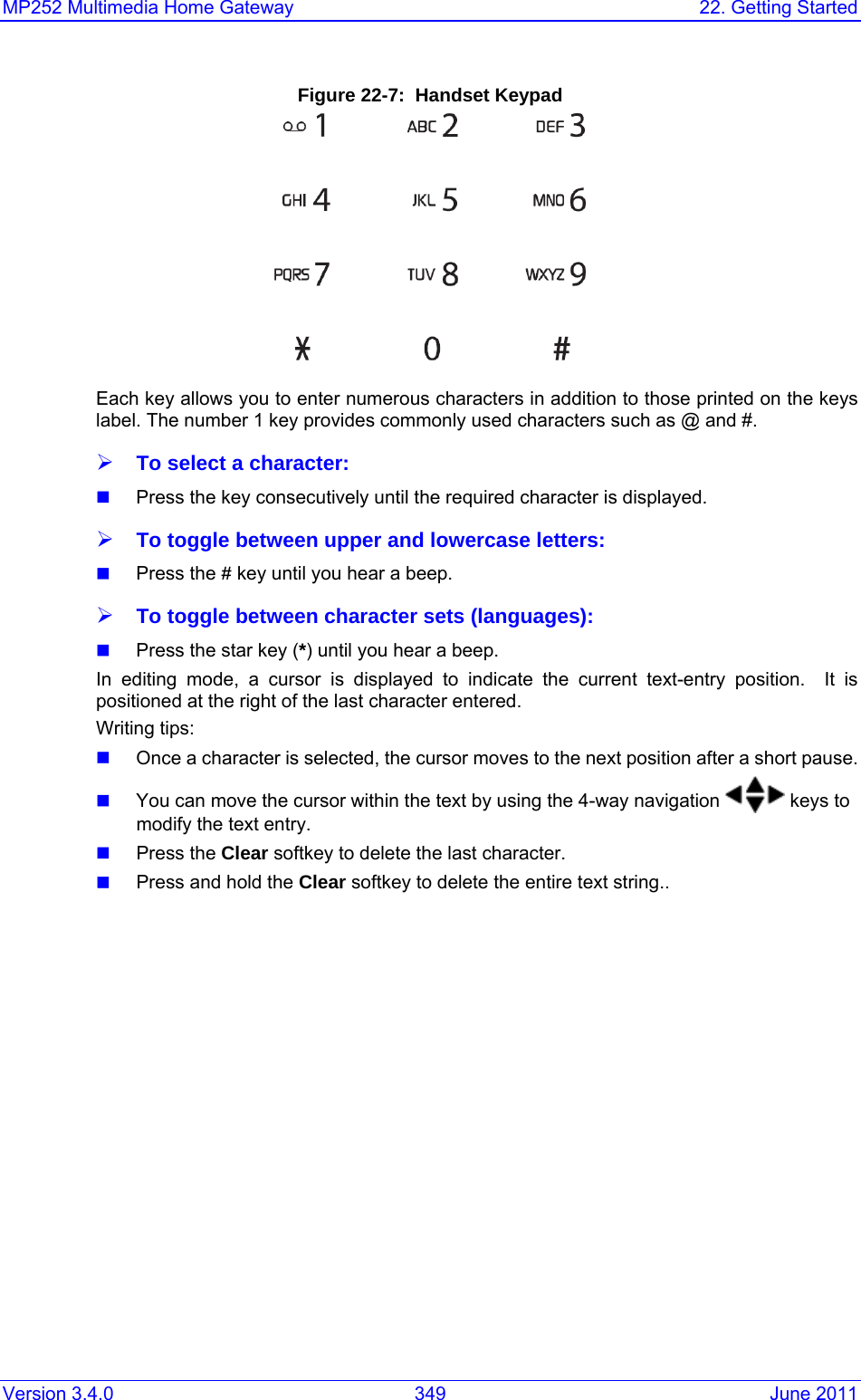
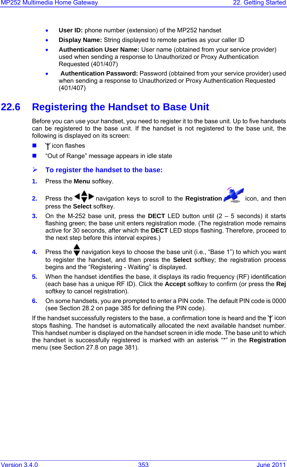
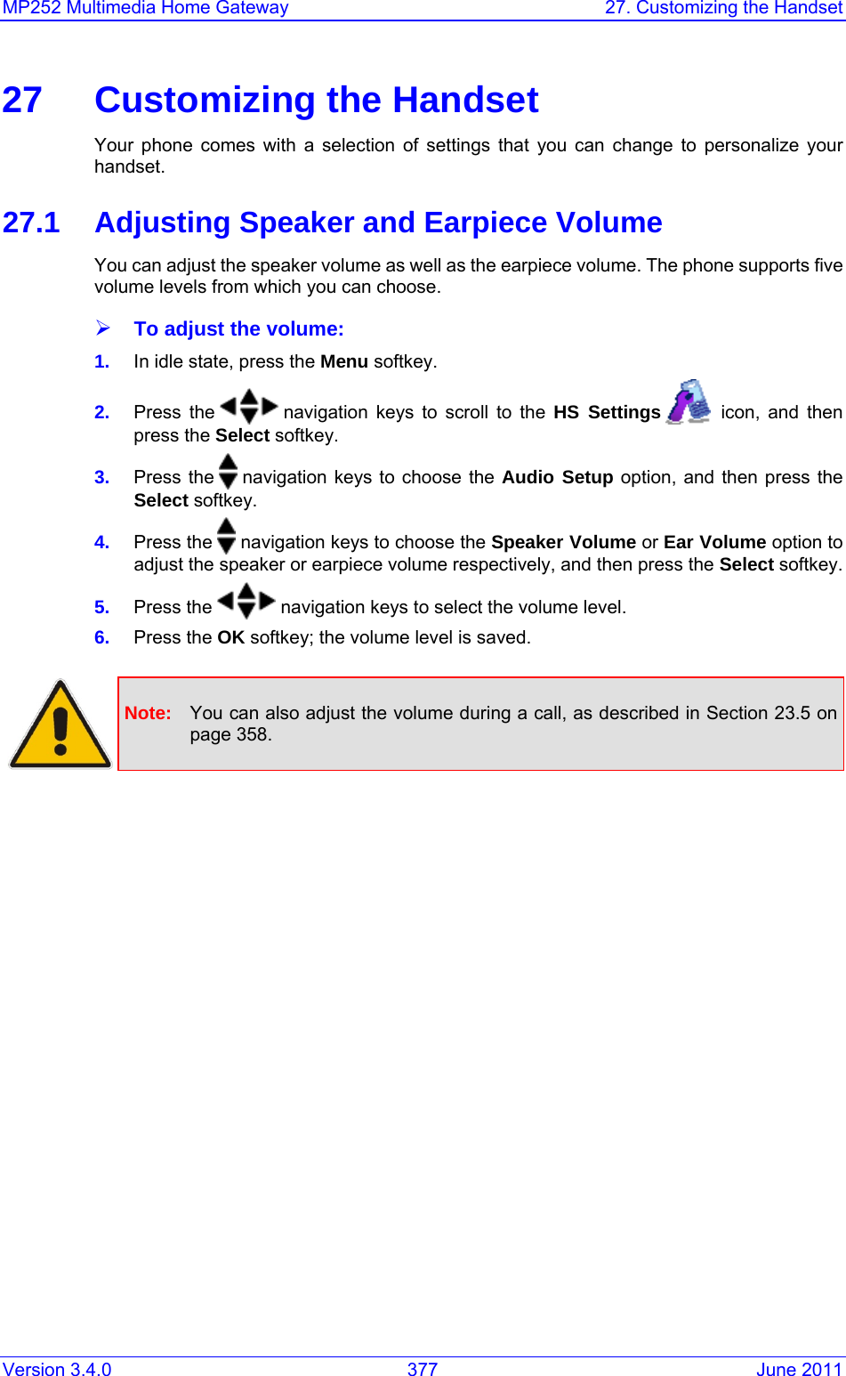
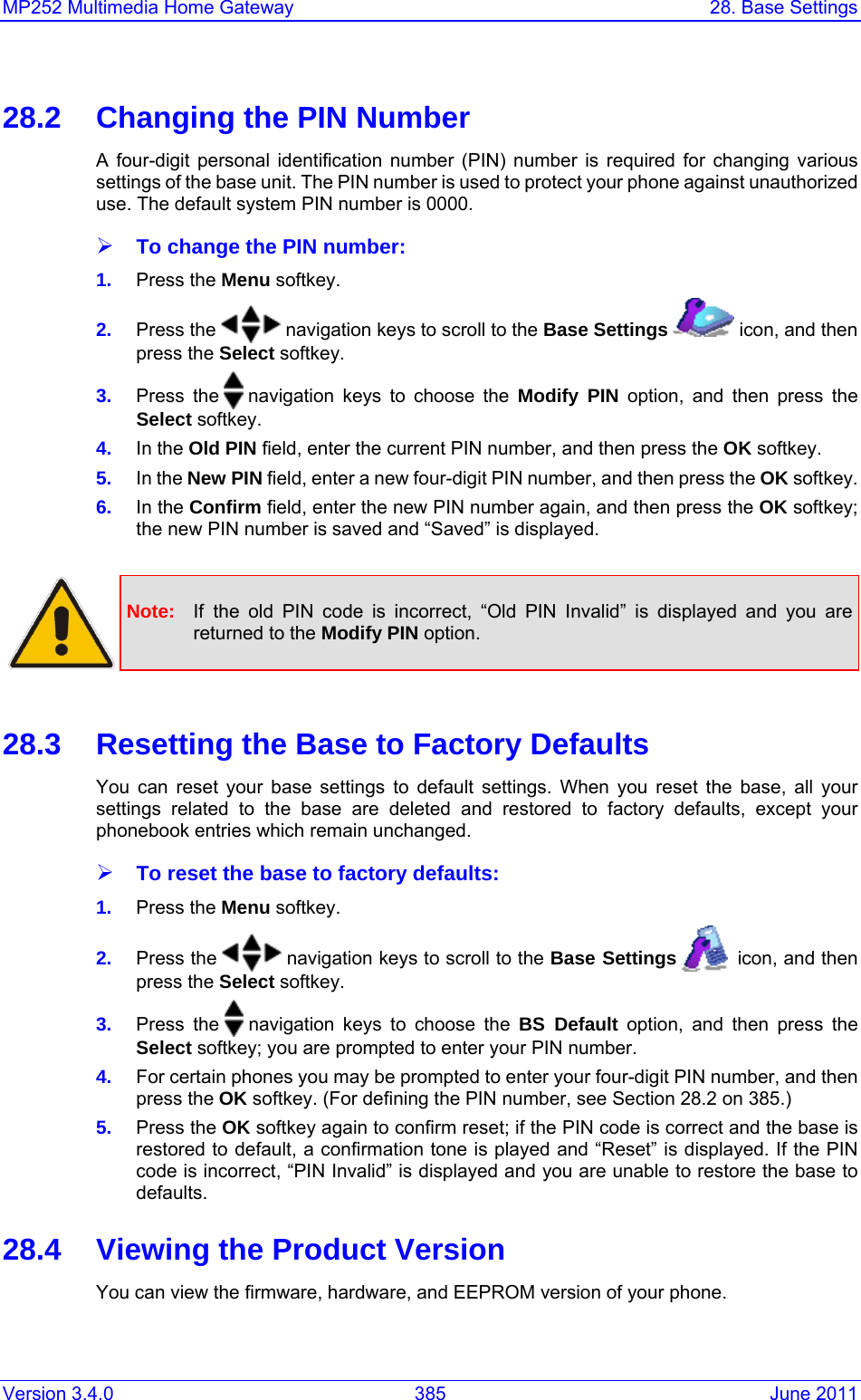
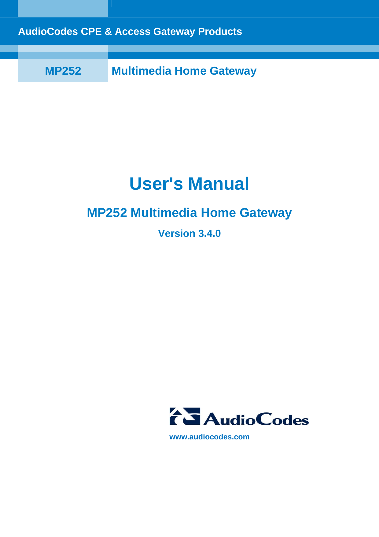
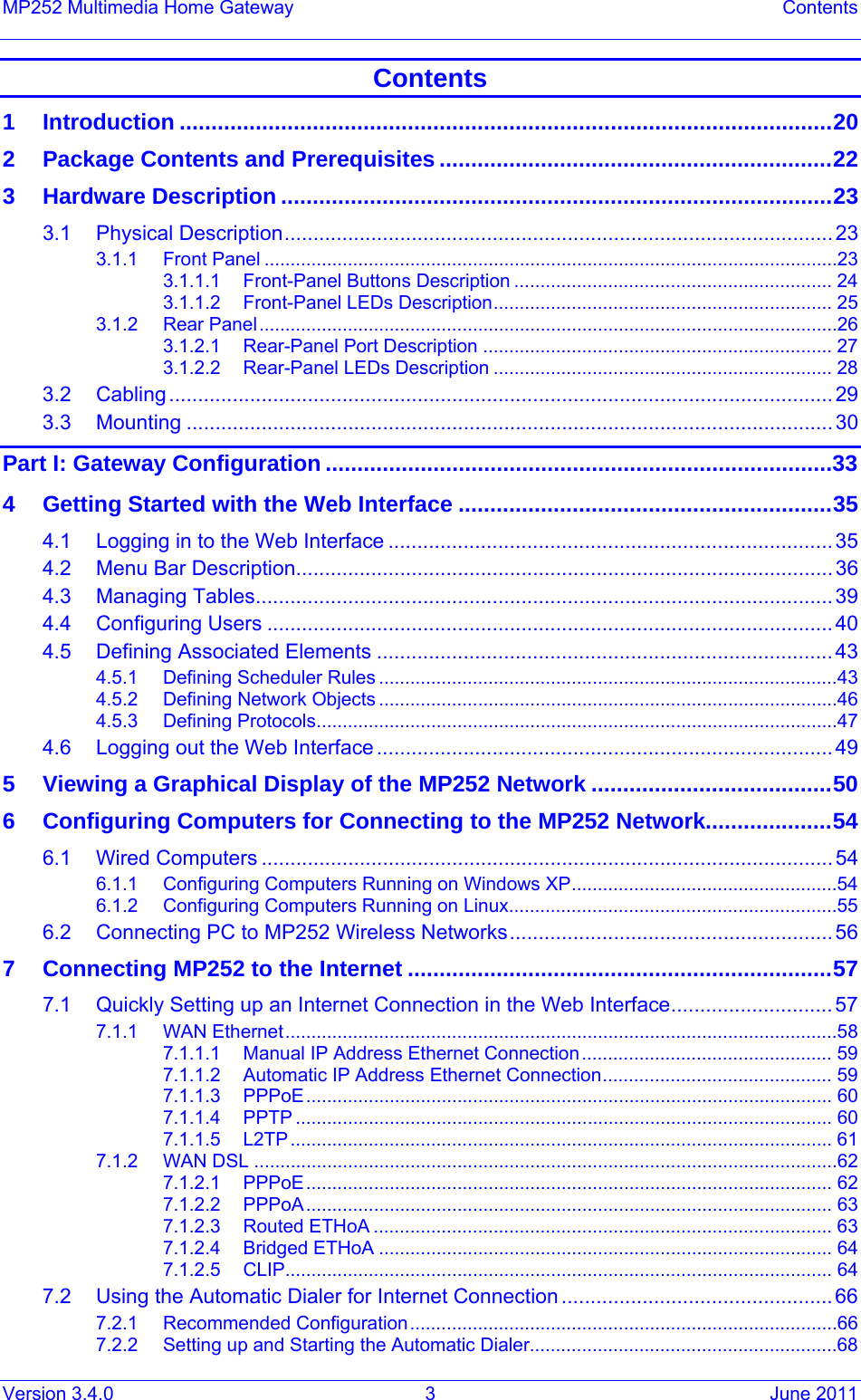
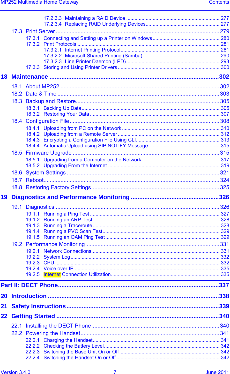
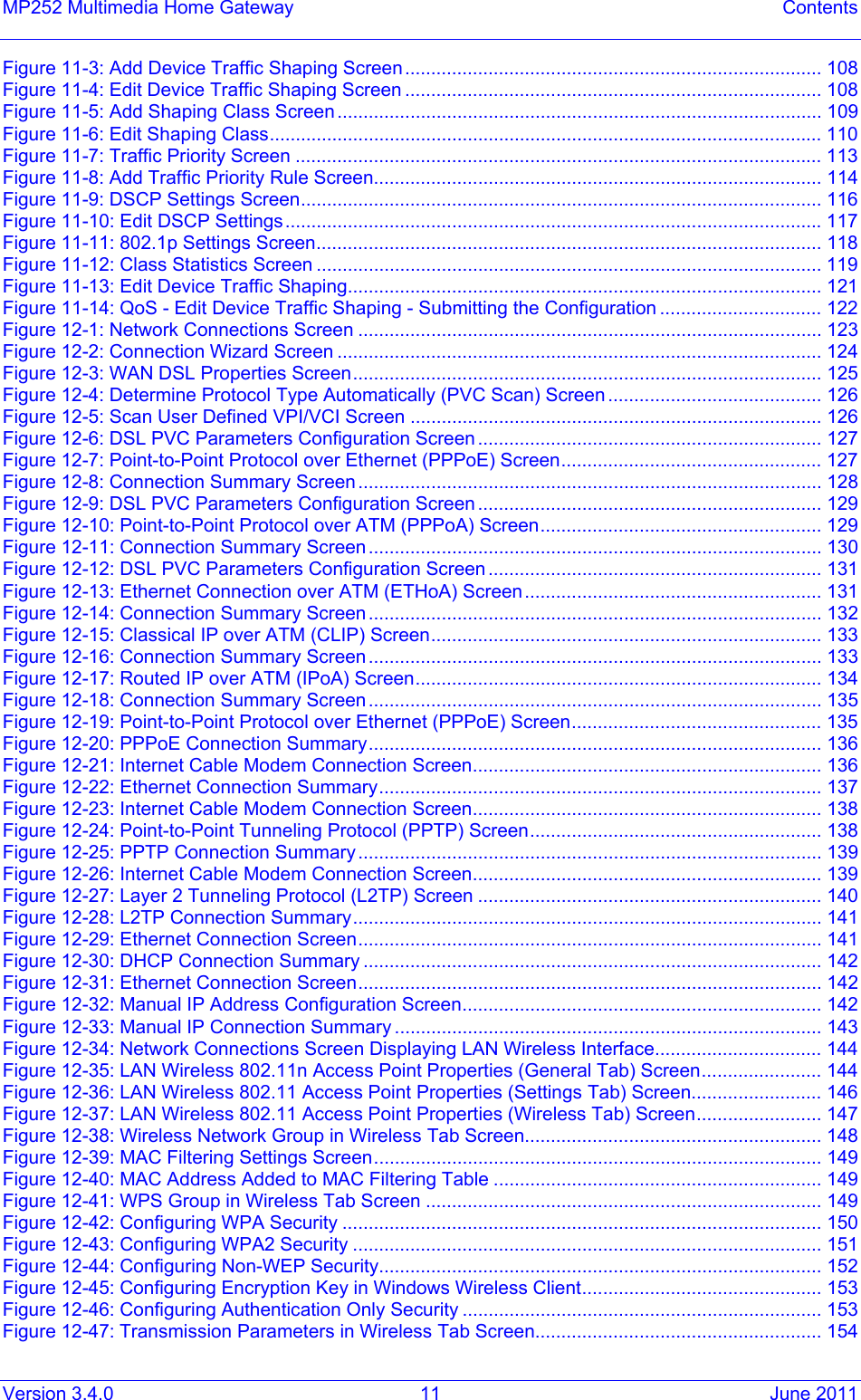
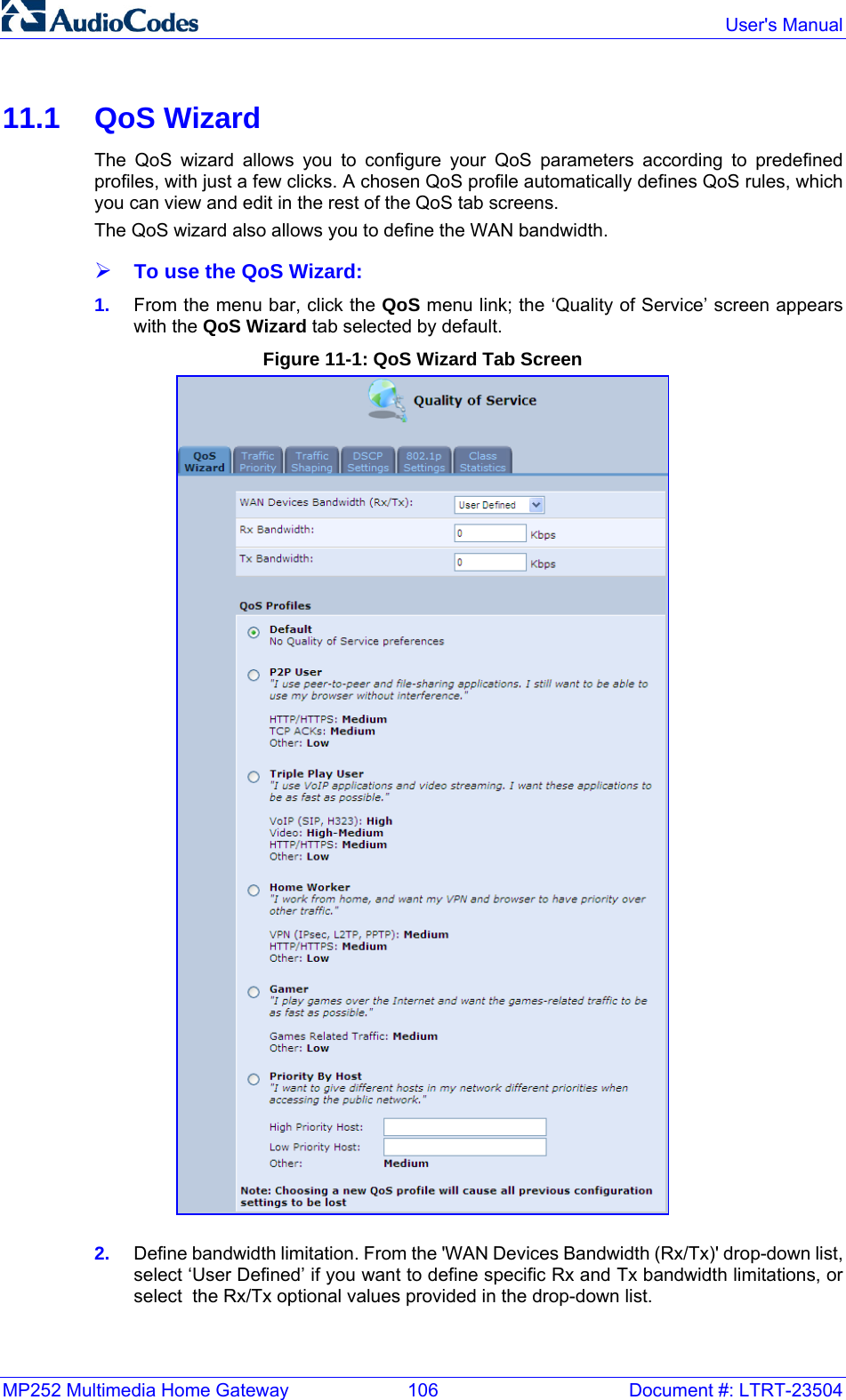
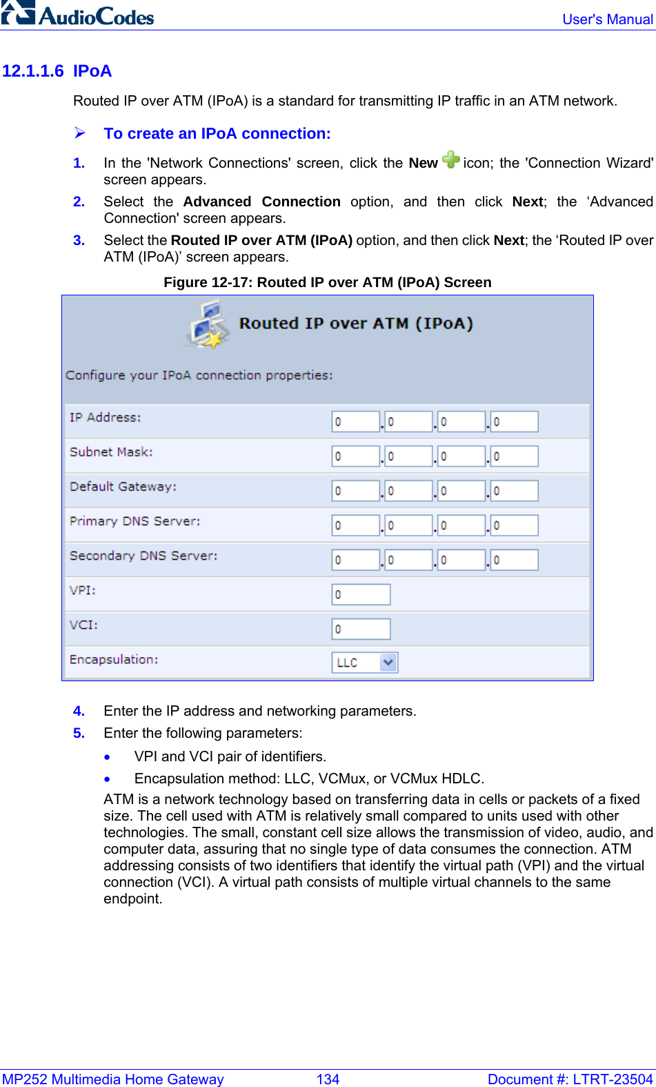
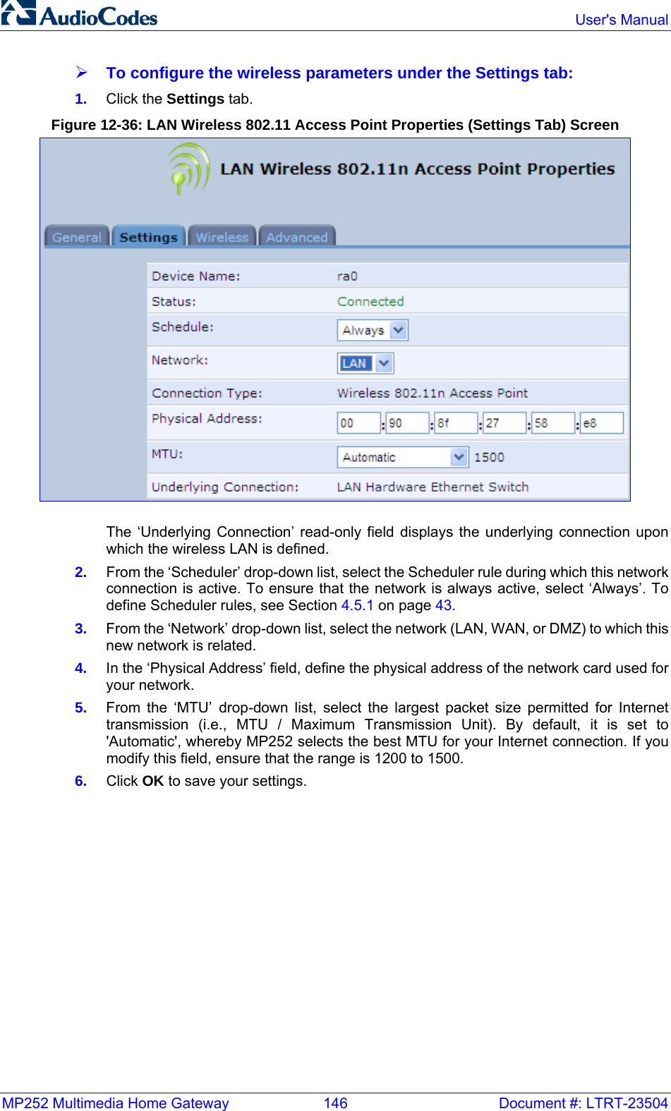
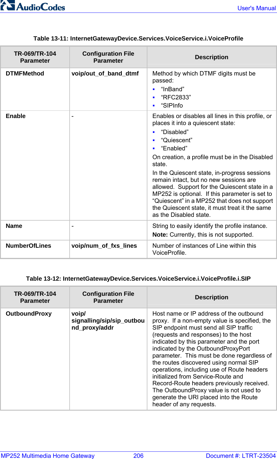
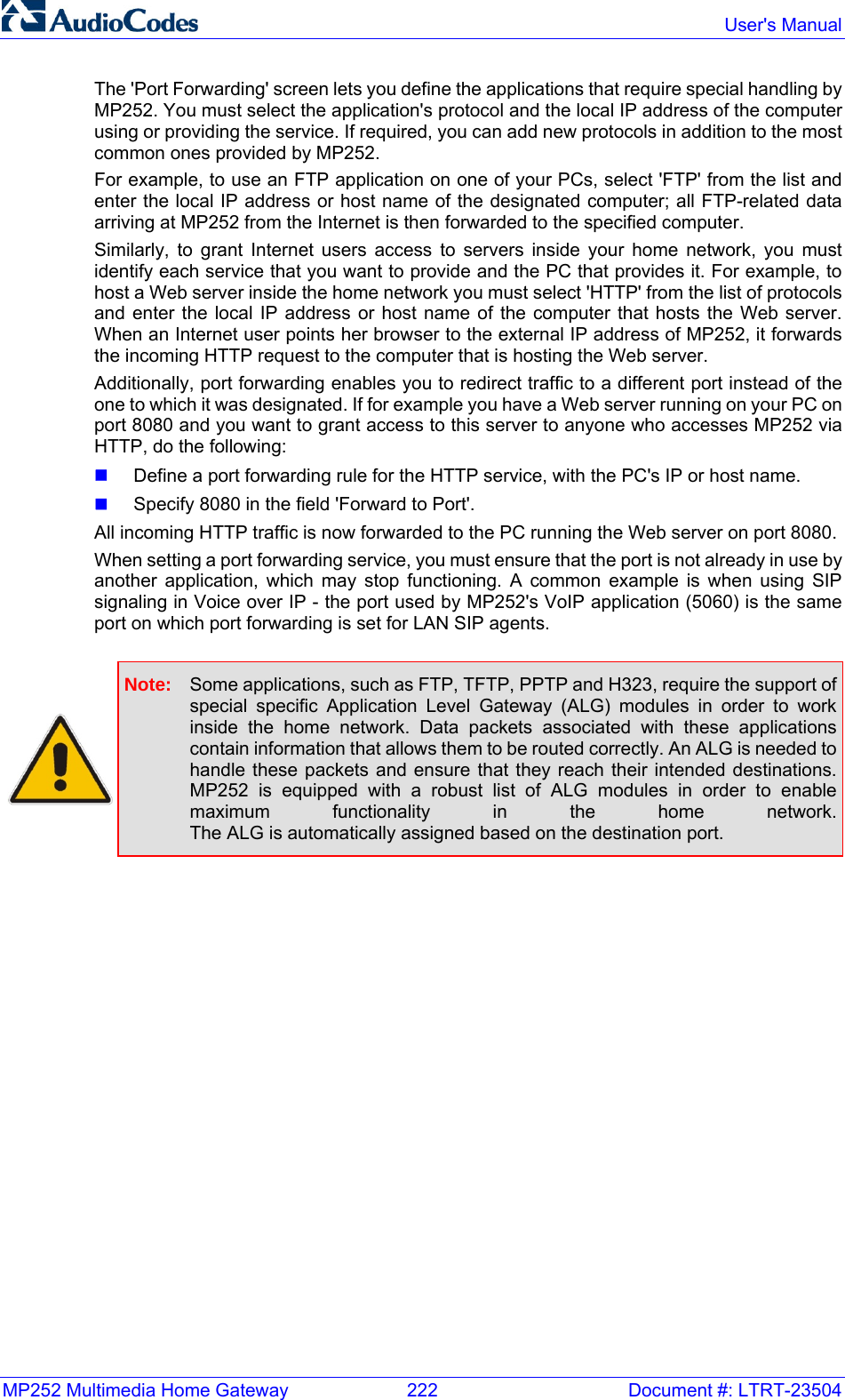
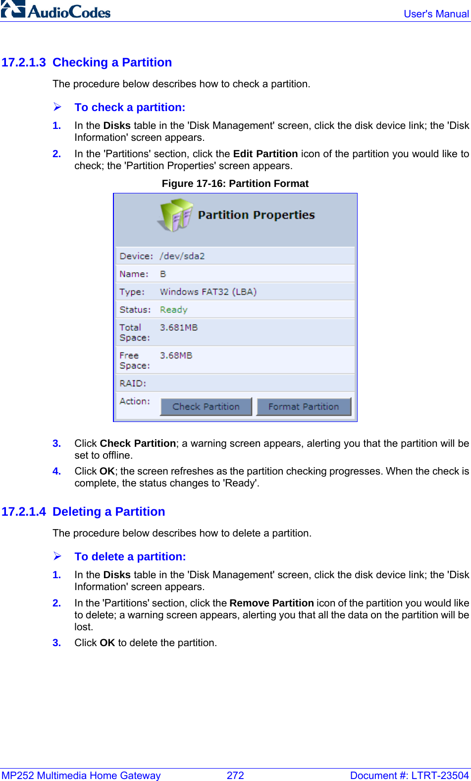
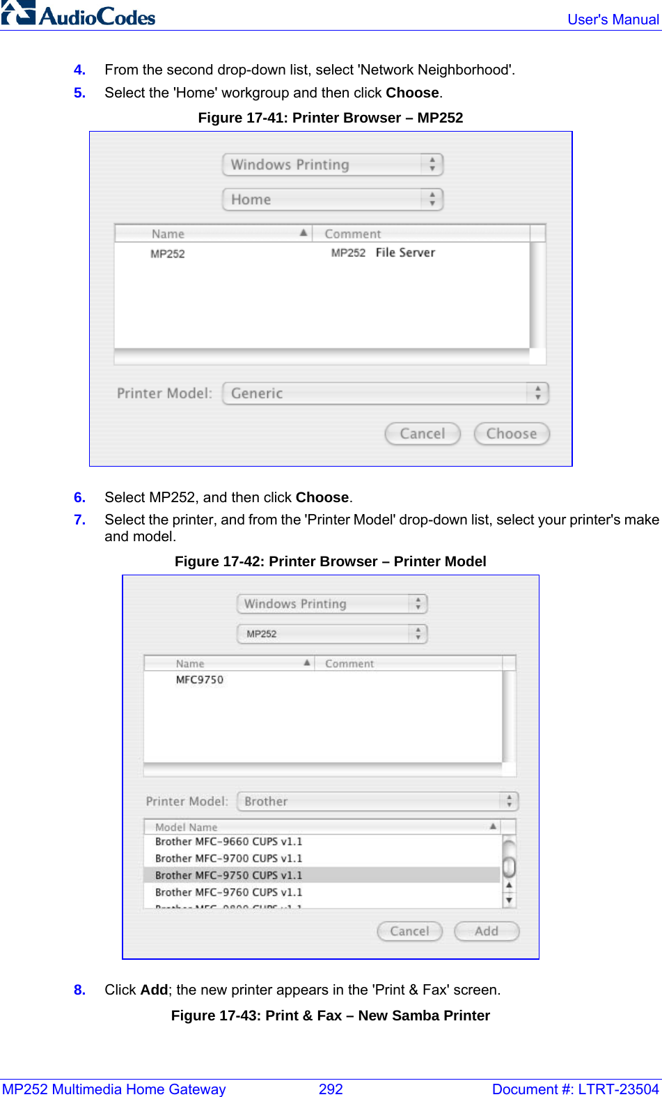
![MP252 Multimedia Home Gateway 82 Document #: LTRT-23504 User's Manual all the required digits. A digit map is defined either by a (case insensitive) "string" or by a list of strings. Each string in the list is an alternative numbering scheme, specified either as a set of digits or as an expression over which MP252 attempts to find a shortest possible match. The syntax that can be used in each numbering scheme is described in the table below. Dial Plans: A dial plan translates specific patterns into specific SIP destination addresses. For example, dial plan rule "4xxx=Line_\\\@10.1.2.3" sends a dialed number consisting of the digit “4” followed by any three digits to IP address 10.1.2.3. The syntax of the pattern on the left of the '=' sign is described in the table below. Table 8-3: Dial Plan (for Left of '=' Sign) and Digit Map Syntax Type Syntax Digit A digit from "0" to "9". DTMF A digit, or one of the symbols "A", "B", "C", "D", "#", or "*". Extensions may be defined. Wildcard The symbol "x" which denotes any digit ("0" to "9"). Range One or more DTMF symbols enclosed between square brackets ("[" and "]"). Sub-range Two digits separated by a hyphen ("-") which matches any digit between and including the two. The subrange can only be used inside a range construct, i.e., between "[" and "]". Position A period (".") which matches an arbitrary number, including zero, of occurrences ofthe preceding construct. For example: [2-9]11|0|100|101|011xxx.|9011xxx.|1[2-9]xxxxxxxxx|91[2-9]xxxxxxxxx|9[2-9]xxxxxx|*xx|[8]xxxx|[2-7]xxx [2-9]11: 911 rule: 211, 311, 411, 511, 611, 711, 811, 911 are dialled immediately 0: Local operator rule 100: Auto-attendant default extension 101: Voicemail default extension 011xxx.: International rule without prefix 9011xxx.: International rule with prefix 1[2-9]xxxxxxxxx: LD rule without prefix 91[2-9]xxxxxxxxx: LD rule with prefix 9[2-9]xxxxxx: Local call with prefix *xx: 2-digit star codes [1-7]xx: A regular 3-digit extension that does not start with 9 or 8 is dialed immediately [2-7]xx: A regular 3-digit extension that does not start with 9, 8, or 1 is dialed immediately [2-7]xxx: A regular 4-digit extension that does not start with 9, 8, or 1 is dialed immediately [8]xxx: A 3-digit extension prefixed with an 8 (routes calls directly to voicemail of extension xxx) [8]xxxx: A-4 digit extension prefixed with an 8 (routes calls directly to voicemail of extension xxxx)](https://usermanual.wiki/VTech-Telecommunications/80-7597-00.Users-manual/User-Guide-1504581-Page-86.png)
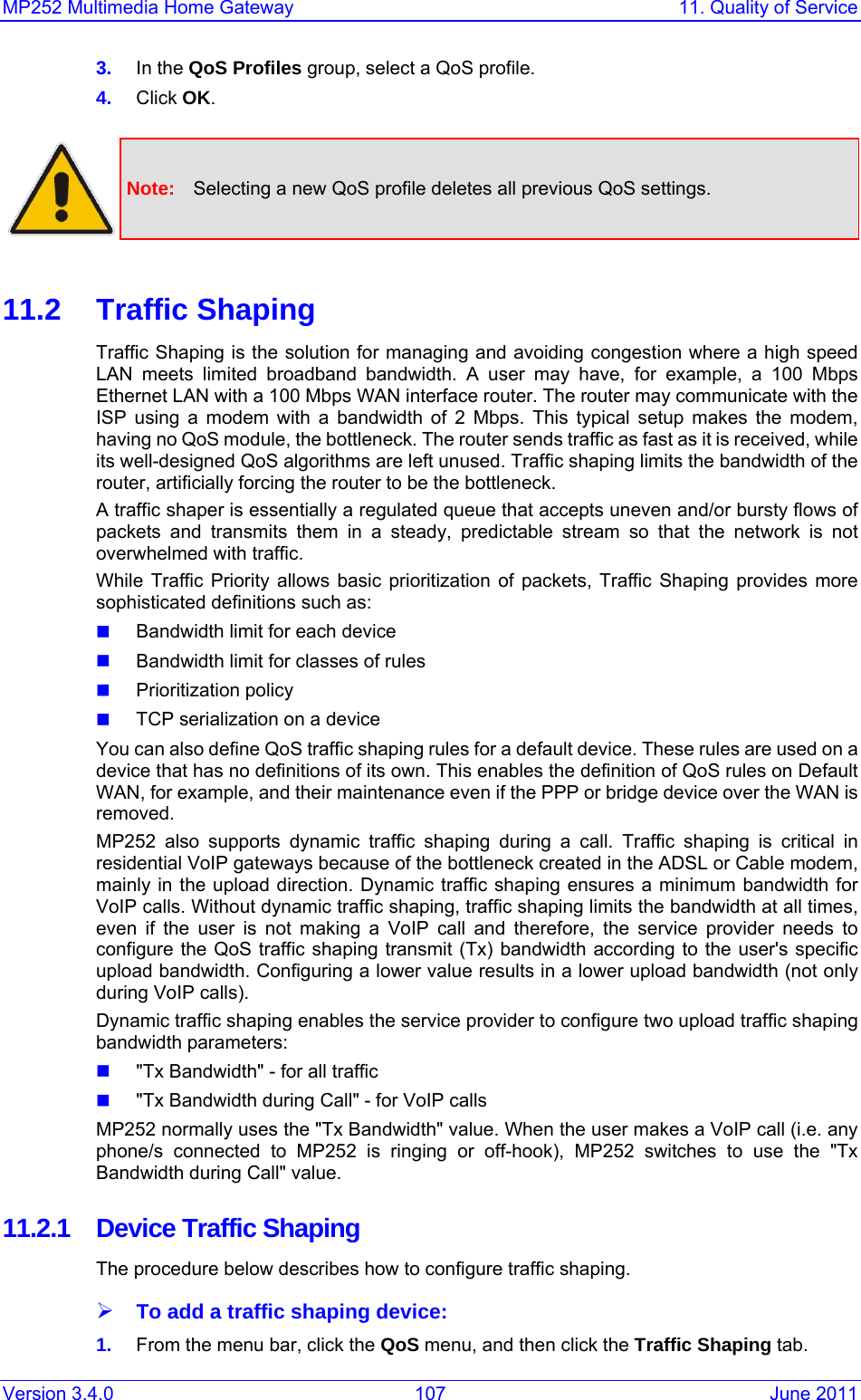
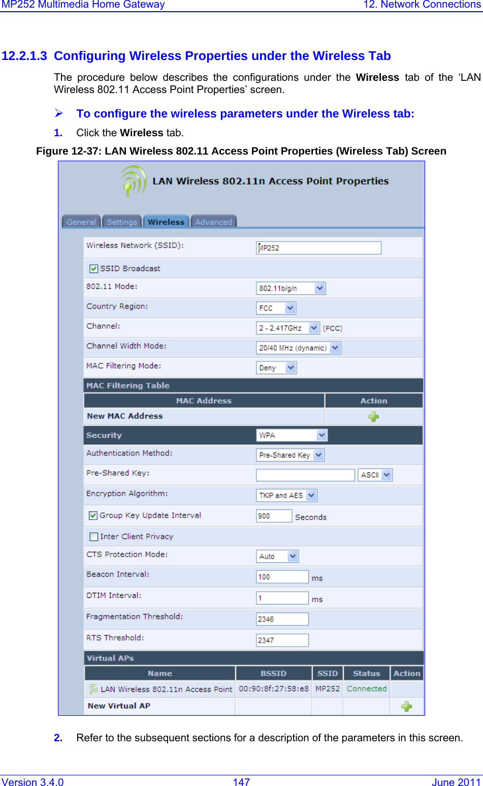
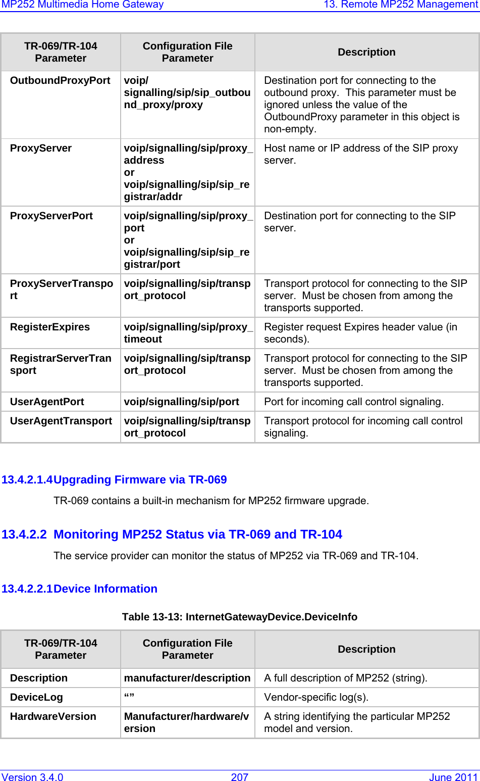
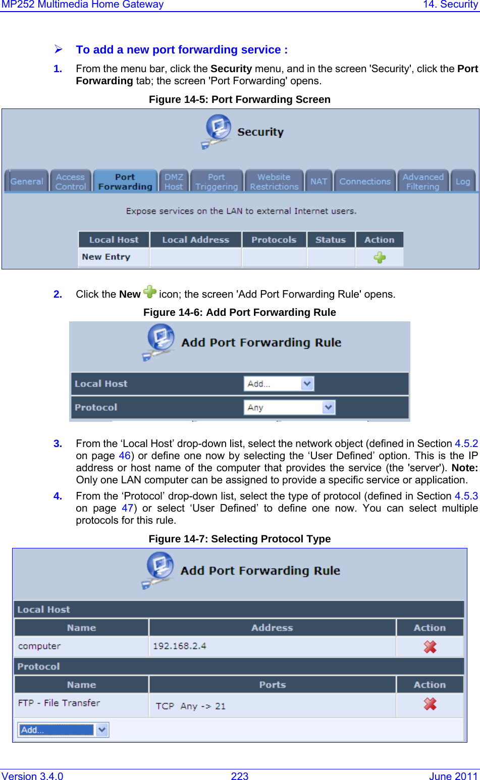

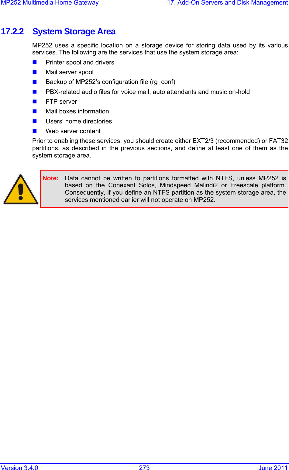
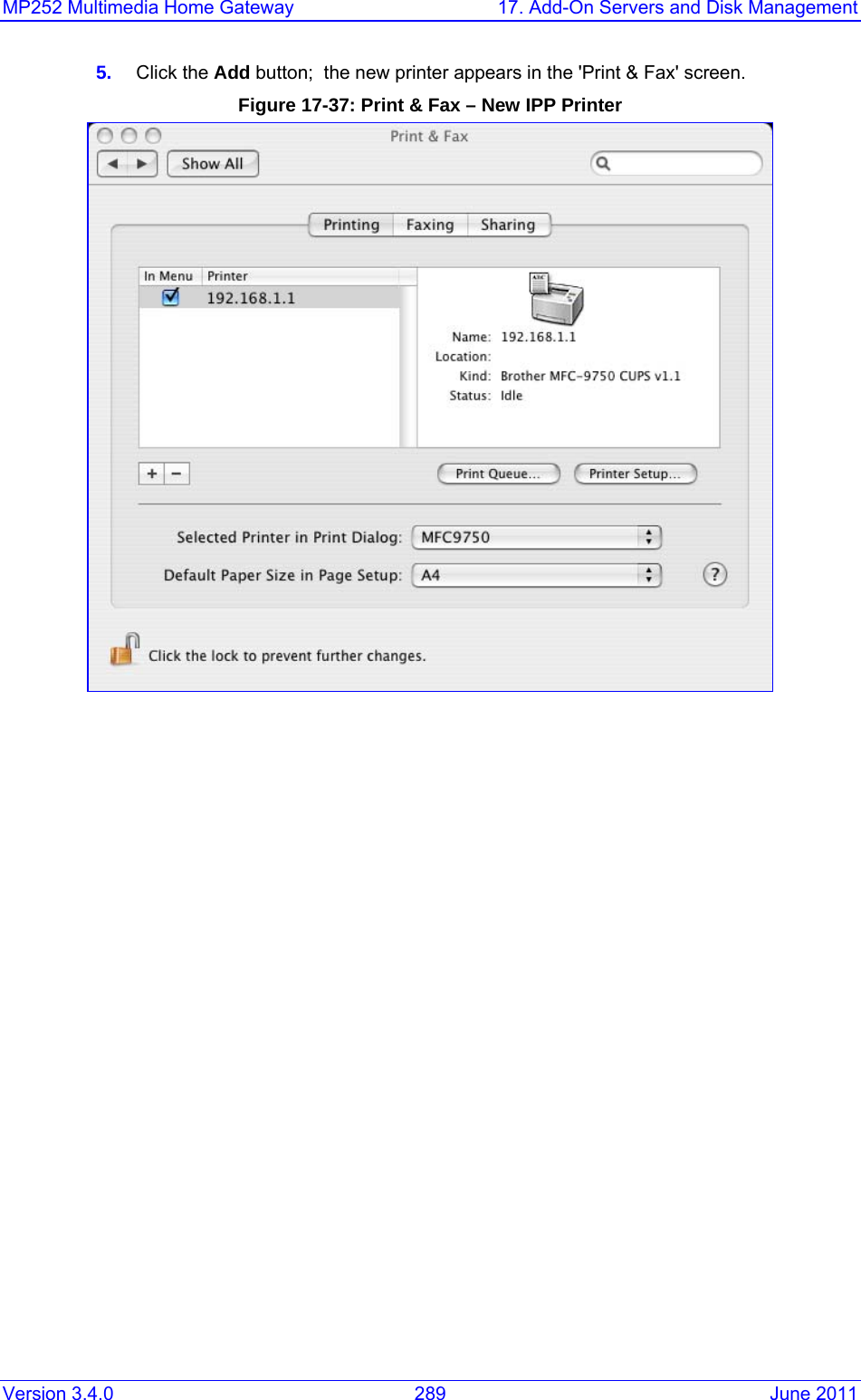
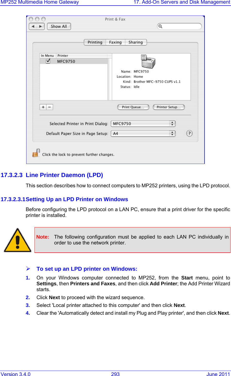
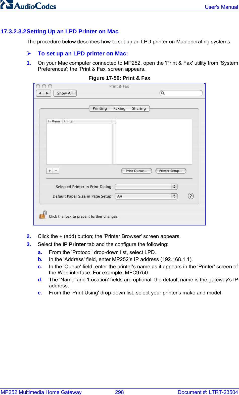
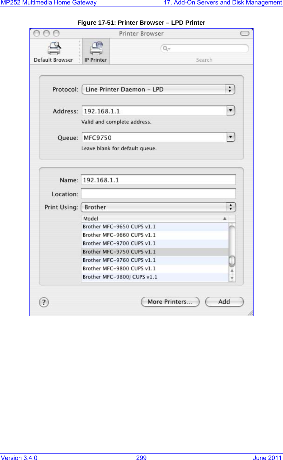
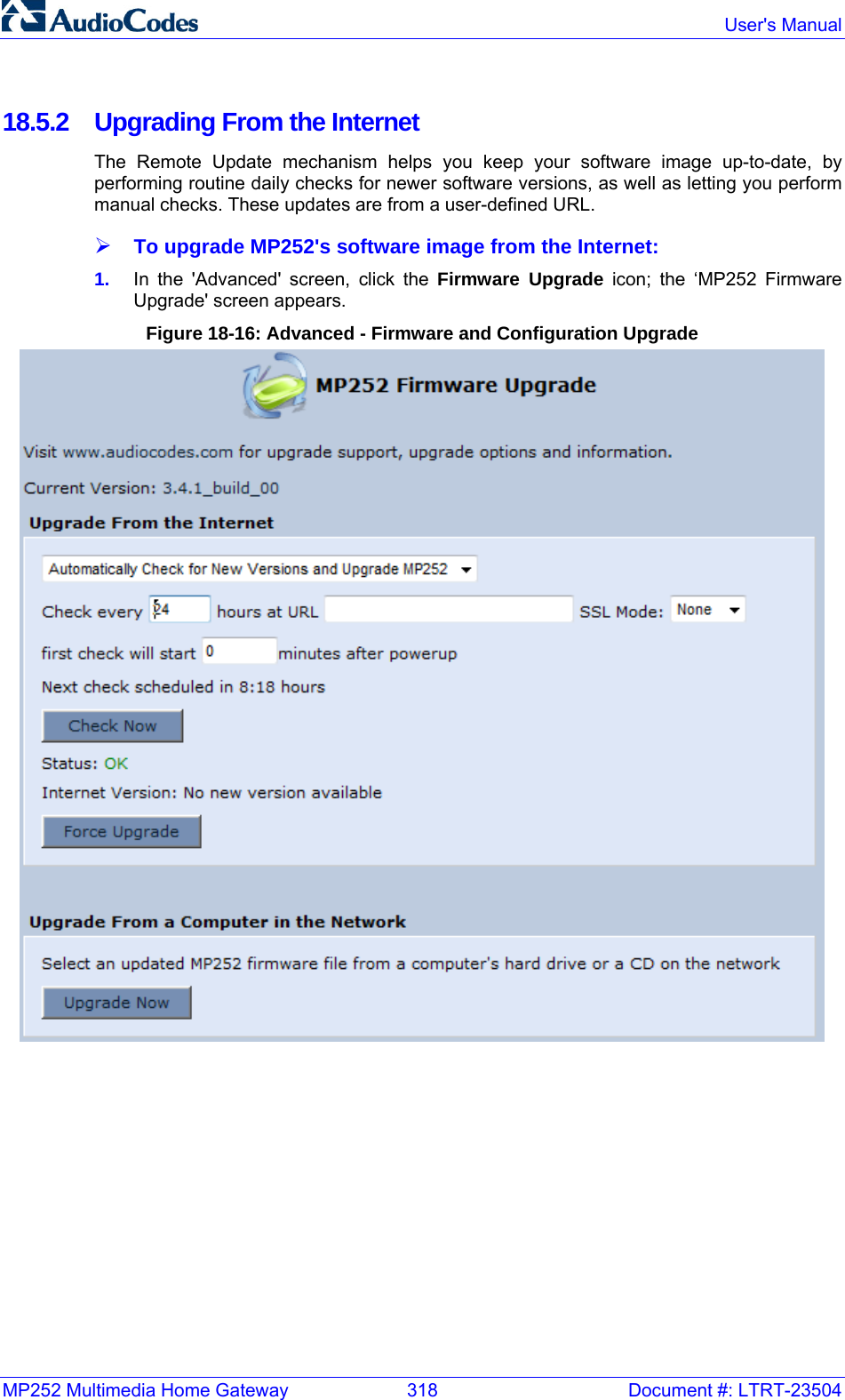
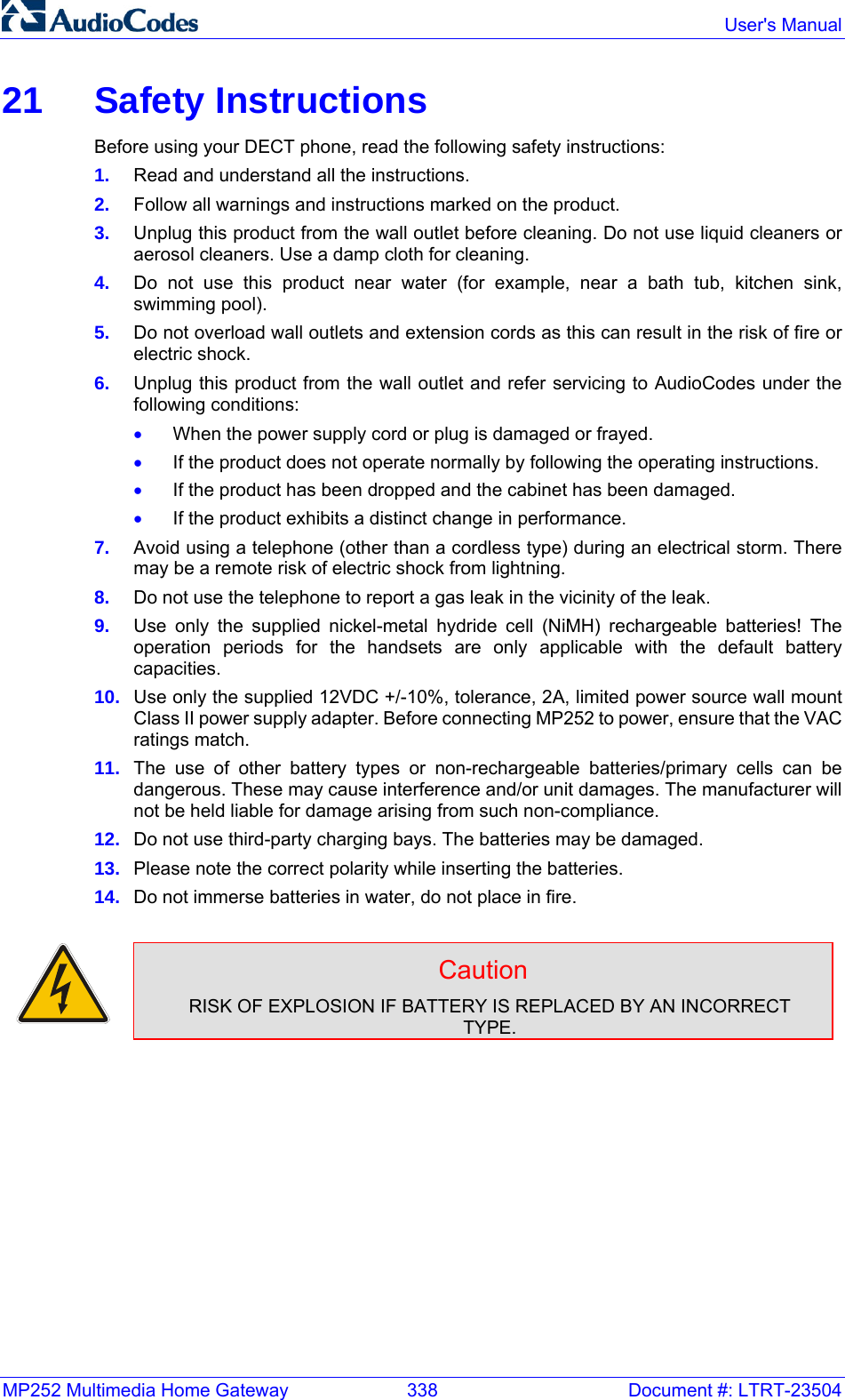
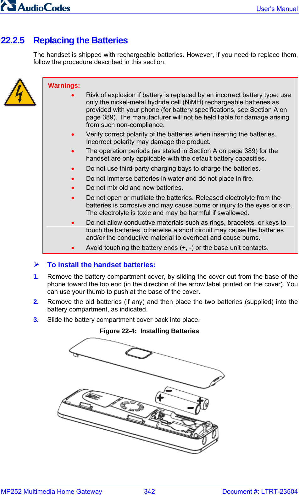
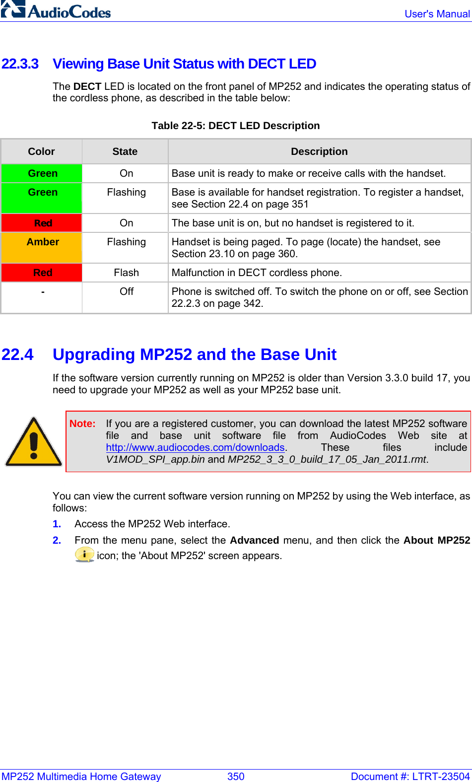
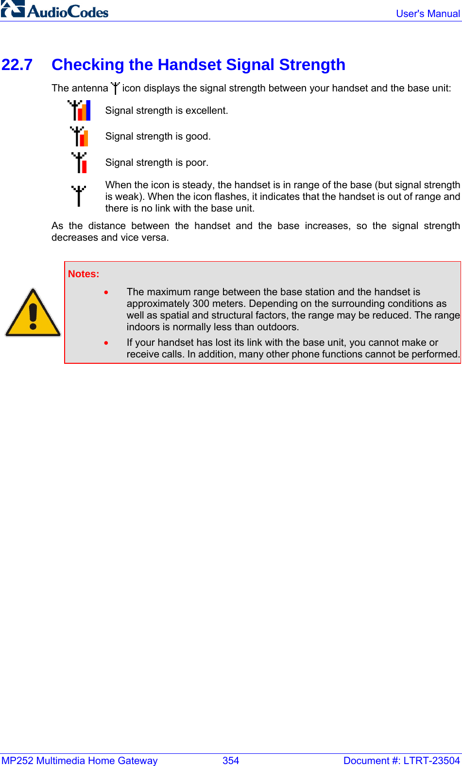
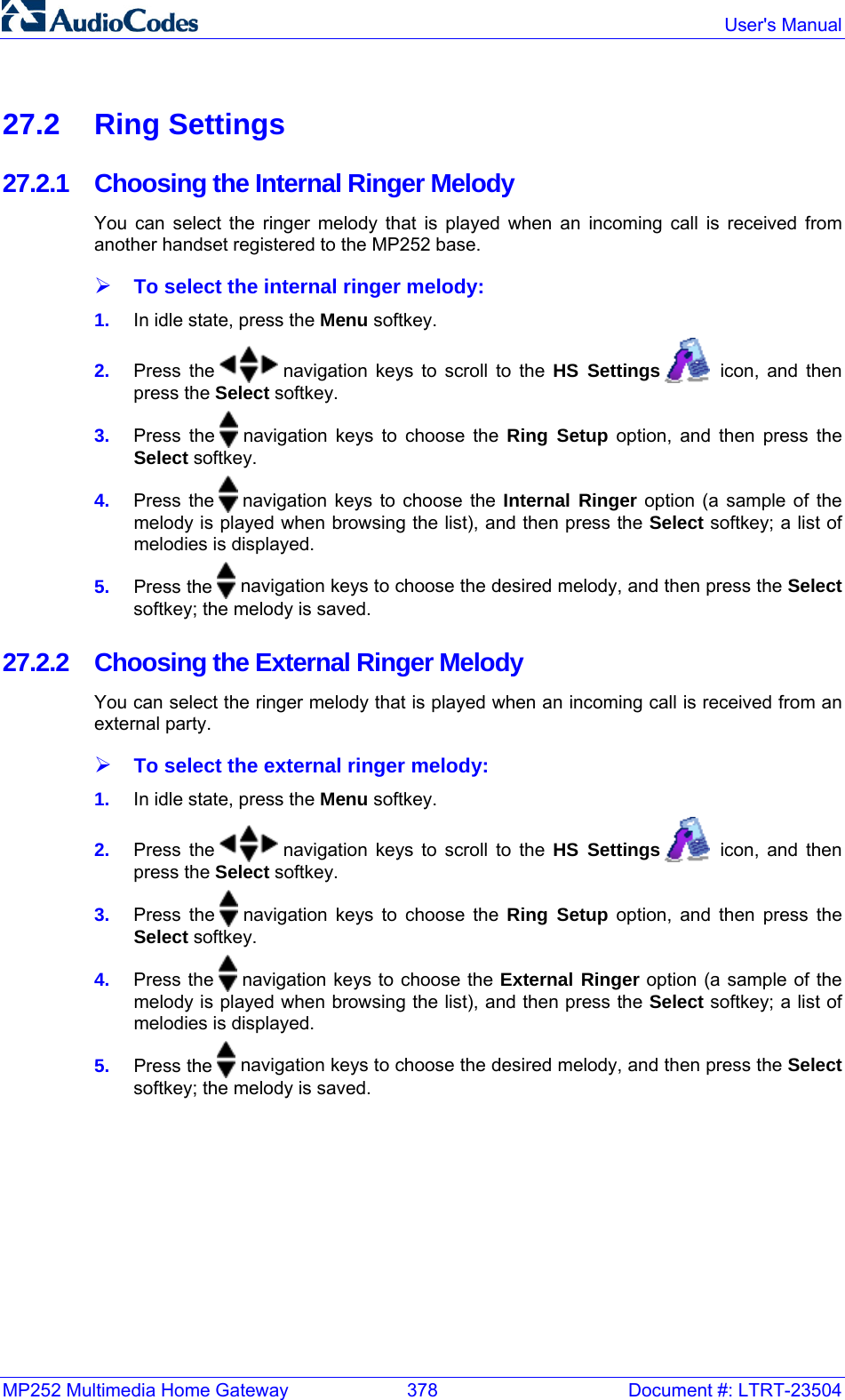
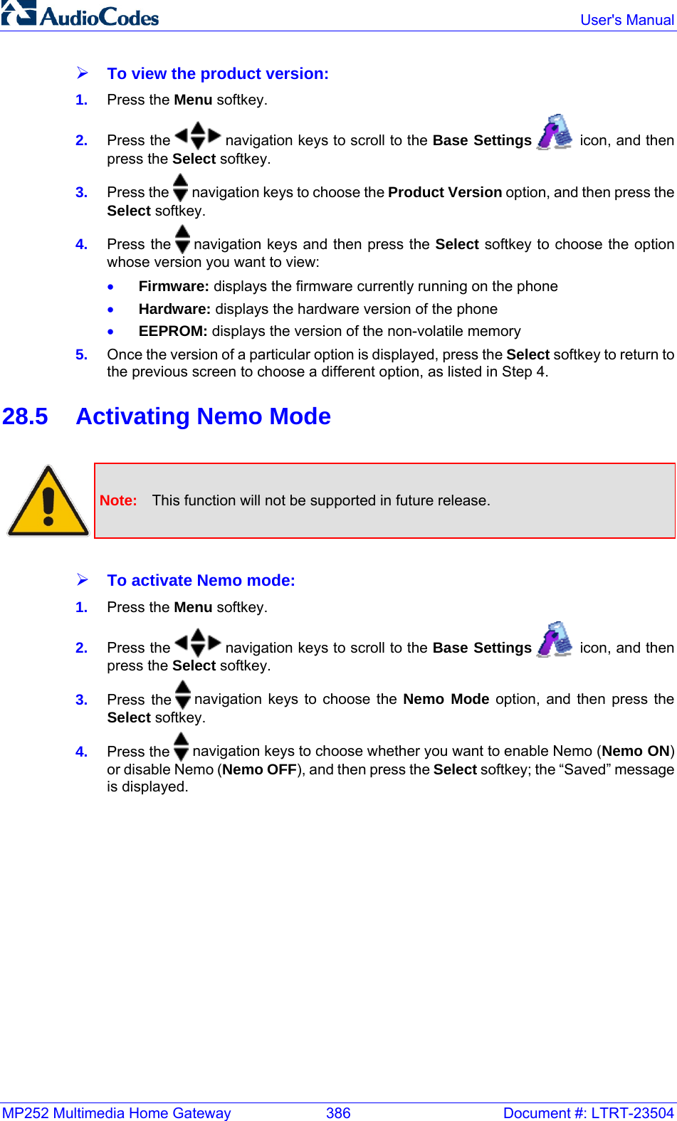
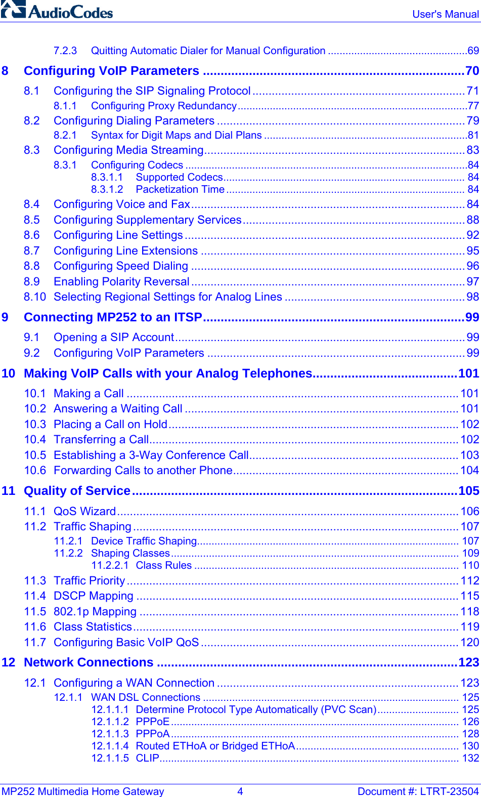
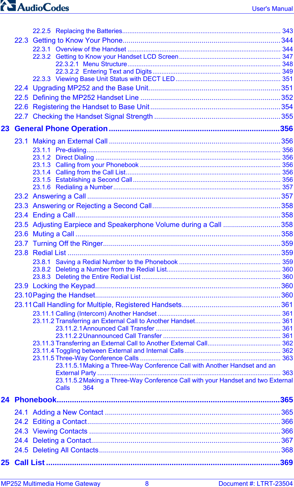
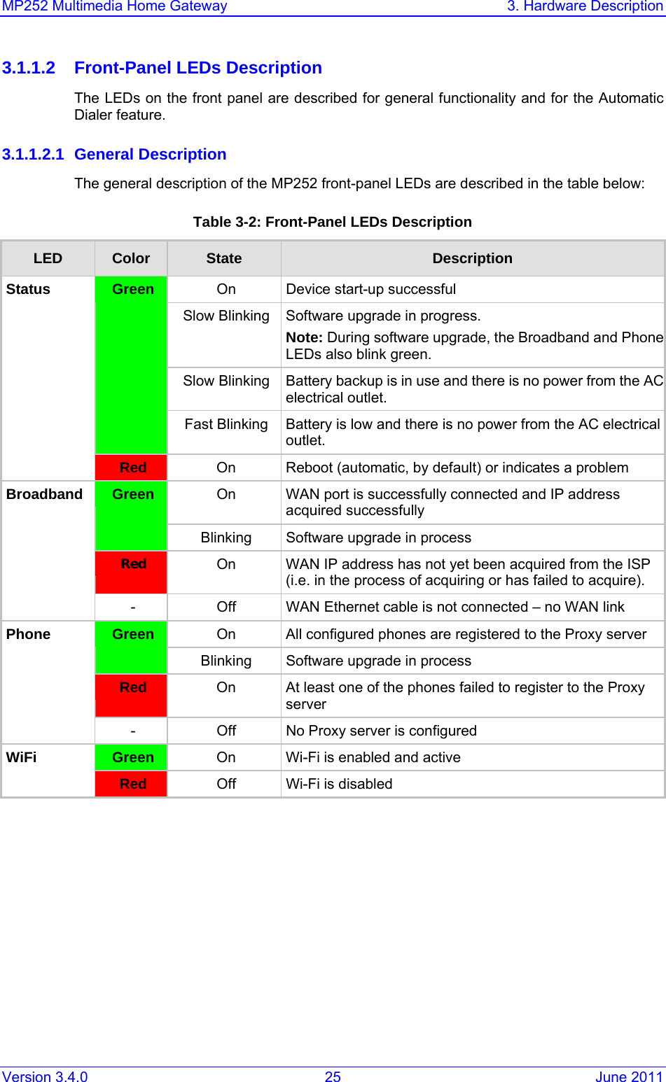
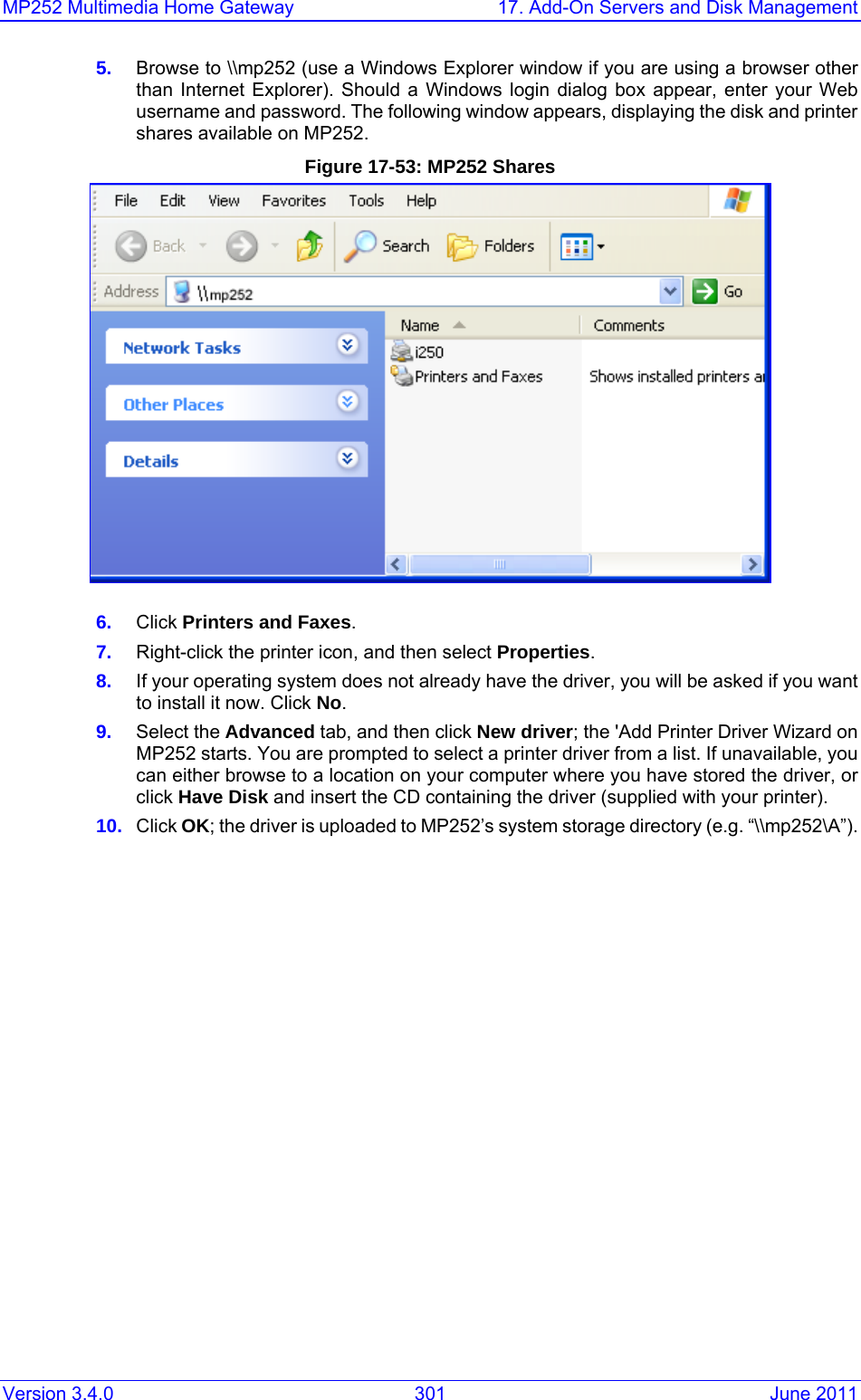
![MP252 Multimedia Home Gateway 300 Document #: LTRT-23504 User's Manual 4. Click Add; the new printer appears in the 'Print & Fax' screen. Figure 17-52: Print & Fax – New LPD Printer 17.3.3 Storing and Using Printer Drivers As explained earlier in this chapter, to use a shared printer connected to MP252, a driver for the printer must be installed on the LAN computer from which the print job is to be sent. You can use the MP252 file server to store printer drivers. The drivers should be uploaded from a Windows computer and stored in the system storage area that you have created on one of the disk partitions. The printer can then be installed on other LAN computers using the driver stored on MP252. ¾ To upload the driver files to MP252: 1. From Window's Start menu, click Run, and then type "cmd" to open a command shell. 2. At the prompt, type net use to view the list of shares and their status. 3. Type net use /del \\mp252\share-B to delete the specific network mapping entry. Alternatively, you can use net use /del * to delete all network mapping entries. 4. Type net use * \\openrg\print$ [Admin's password] [/user:admin]. This ensures that you are logged into the print server using the Admin user and have the permissions to upload files.](https://usermanual.wiki/VTech-Telecommunications/80-7597-00.Users-manual/User-Guide-1504581-Page-304.png)

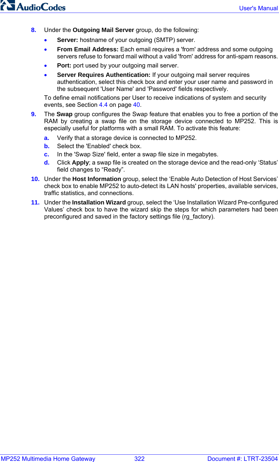
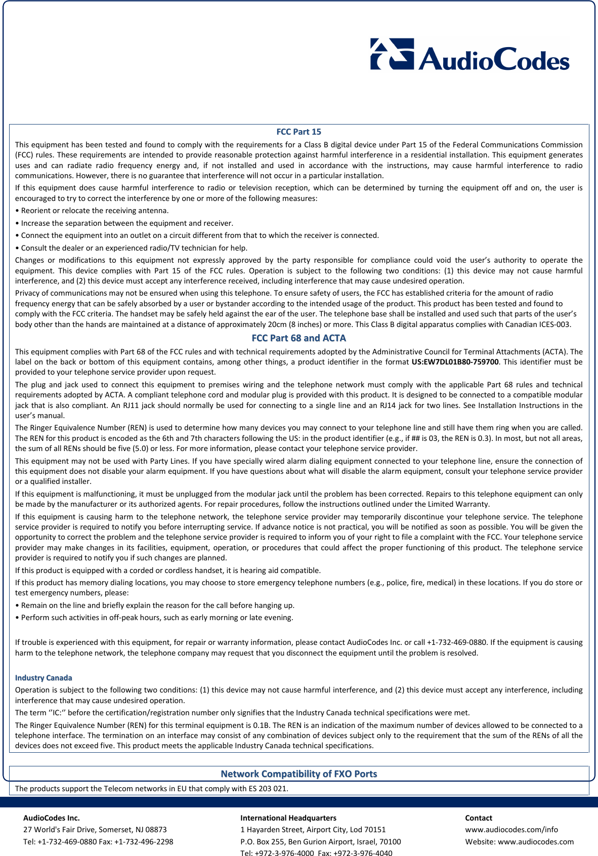
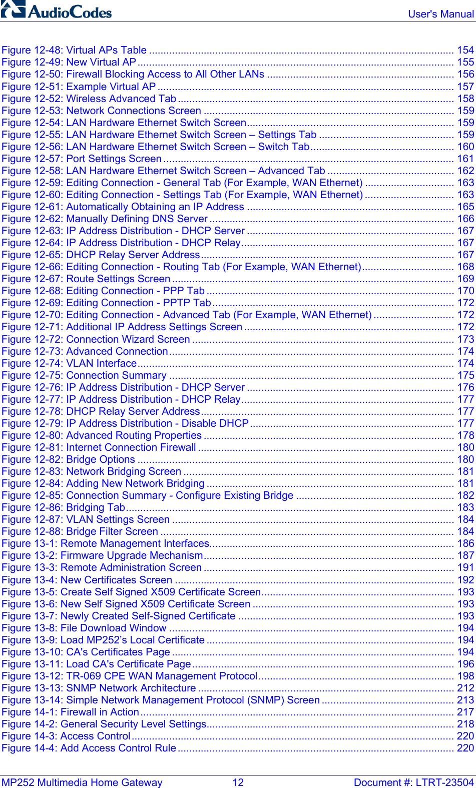
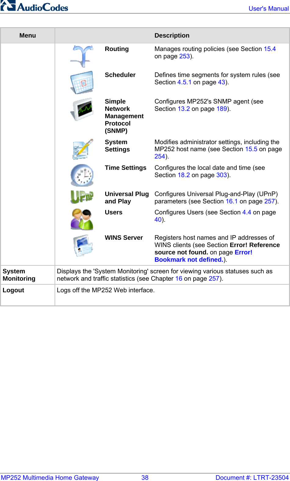
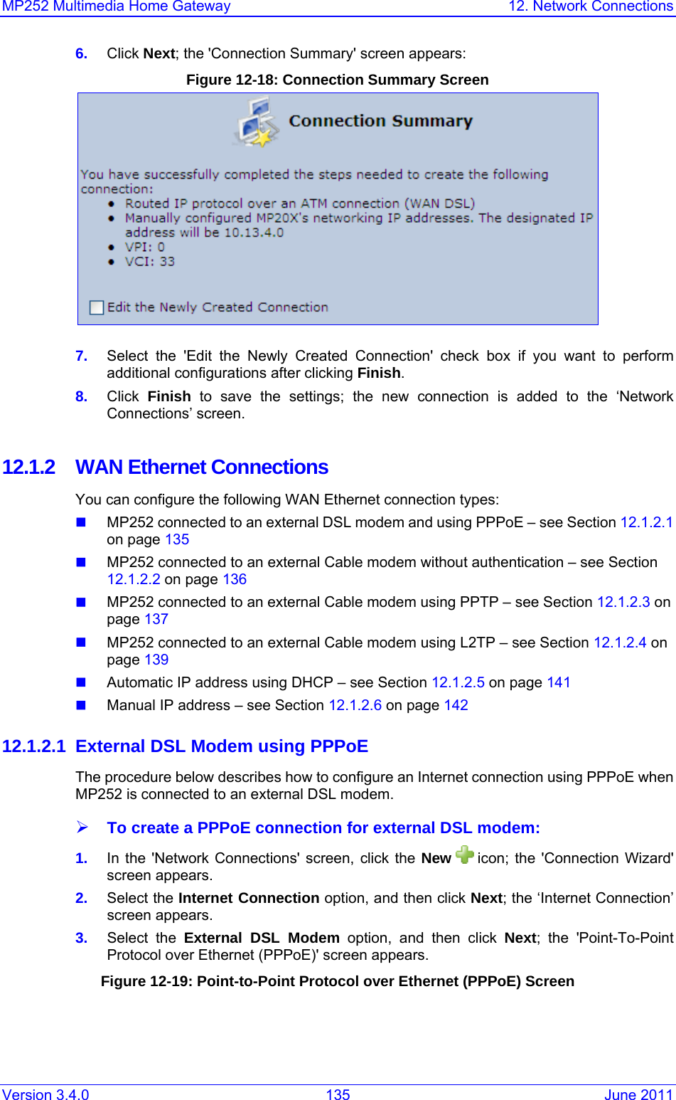
![MP252 Multimedia Home Gateway 314 Document #: LTRT-23504 User's Manual openssl des3 -in <original file> -out <encrypted file> -k <password> -S <salt value> Where, • <original file> is the original clear-text configuration file (*.cfg or *.ini file). • <encrypted file> is the output file (an encrypted *.cfx or *.inx file). • <password> is the password that is used to encrypt the file. • <salt value> is the 8 bytes of a special key value that is combined with the password. The format is 16 hexadecimal digits [0-9,A-F]. An example of this command is shown below: openssl des3 -in c:\temp\try_enc_conf.cfg -out c:\temp\try_enc_conf.cfx -k MyPassword123456 -S 0123456789ABCDEF Notes: • You can choose any <salt value> – MP252 does not have to know about it.• A password can be pre-configured in MP252, using the following CLI command: rg_conf_set_obscure /rmt_config/password <password> • You can also define the password in a configuration file that you download from the server. • If you don’t define a password in the configuration file, a default password is used. Different default passwords are defined per customer, according to the config-file url hostname.](https://usermanual.wiki/VTech-Telecommunications/80-7597-00.Users-manual/User-Guide-1504581-Page-318.png)