VTech Telecommunications 80-7597-00 1.9GHz Cordless Phone User Manual Users manual
VTech Telecommunications Ltd 1.9GHz Cordless Phone Users manual
Contents
- 1. Users manual
- 2. manual
- 3. users manual
- 4. Users Manual
Users manual

Important Product Information for
MP-252 Series
Document #: LTRT
-
23003
T
Th
ha
an
nk
k-
-y
yo
ou
u
f
fo
or
r
C
Ch
ho
oo
os
si
in
ng
g
A
Au
ud
di
io
oC
Co
od
de
es
s
This important product information includes Regulatory and Safety information.
Before you start using this product, please read the Safety Instructions provided. These Instructions can also be downloaded from the AudioCodes Website at
http://www.audiocodes.com/library. This document, the Installation Manual and User’s Manual (as well as software files and other documentation) can be
downloaded from the AudioCodes Website at http://www.audiocodes.com/downloads. Check that all items as listed in the Installation Manual are supplied in the
shipped package. If any items are missing or if you have any queries, contact your AudioCodes sales representative. If your product was purchased directly from
AudioCodes, then contact support@audiocodes.com. If the product was purchased from AudioCodes’ Distributors, Partners, or Resellers, then use the contact details
provided by these sellers.
W
Wa
ar
rn
ni
in
ng
g
The device will be inoperable when the mains power fails and the battery backup is not connected.
I
In
nd
du
us
st
tr
ry
y
C
Ca
an
na
ad
da
a
N
No
ot
ti
ic
ce
e
This equipment meets the applicable Industry Canada Terminal Equipment technical specifications. This is confirmed by the registration numbers. The abbreviation,
IC, before the registration number signifies that registration was performed based on a declaration of conformity indicating that Industry Canada technical
specifications were met. It does not imply that Industry Canada approved the equipment.
F
Fo
or
r
C
Cu
us
st
to
om
me
er
rs
s
i
in
n
C
Ca
an
na
ad
da
a
This Class [B] digital apparatus complies with Canadian ICES-003.
Cet appareil numérique de la classe [B] est conforme à la norme NMB-003 du Canada.
Operation is subject to the following two conditions: (1) this device may not cause interference, and (2) this device must accept any interference, including
interference that may cause undesired operation of the device.
This device and its antenna(s) must not be co-located or operating in conjunction with any other antenna or transmitter.
The County Code Selection feature is disabled for products marketed in the US/Canada.
I
IC
C
R
Ra
ad
di
ia
at
ti
io
on
n
E
Ex
xp
po
os
su
ur
re
e
S
St
ta
at
te
em
me
en
nt
t
This equipment complies with IC RSS-102 radiation exposure limits set forth for an uncontrolled environment. This equipment should be installed and operated with
minimum distance of 20 cm between the radiator and your body.
S
Sa
af
fe
et
ty
y
N
No
ot
ti
ic
ce
e
1. To avoid risk of fire, use 26 AWG or higher wiring to connect the FXO, ADSL telecom ports.
2. Disconnect TNV circuit connector before removing cover.
3. Unit must be powered only by power limited Class 2 certified power adapter
Ports Safety Status
Ethernet (100Base-TX) SELV
FXS TNV-2
FXO, ADSL TNV-3

AudioCodes Inc.
27 World's Fair Drive, Somerset, NJ 08873
Tel: +1-732-469-0880 Fax: +1-732-496-2298
International Headquarters
1 Hayarden Street, Airport City, Lod 70151
P.O. Box 255, Ben Gurion Airport, Israel, 70100
Tel: +972-3-976-4000 Fax: +972-3-976-4040
Contact
www.audiocodes.com/info
Website: www.audiocodes.com
F
FC
CC
C
P
Pa
ar
rt
t
1
15
5
This equipment has been tested and found to comply with the requirements for a Class B digital device under Part 15 of the Federal Communications Commission
(FCC) rules. These requirements are intended to provide reasonable protection against harmful interference in a residential installation. This equipment generates
uses and can radiate radio frequency energy and, if not installed and used in accordance with the instructions, may cause harmful interference to radio
communications. However, there is no guarantee that interference will not occur in a particular installation.
If this equipment does cause harmful interference to radio or television reception, which can be determined by turning the equipment off and on, the user is
encouraged to try to correct the interference by one or more of the following measures:
• Reorient or relocate the receiving antenna.
• Increase the separation between the equipment and receiver.
• Connect the equipment into an outlet on a circuit different from that to which the receiver is connected.
• Consult the dealer or an experienced radio/TV technician for help.
Changes or modifications to this equipment not expressly approved by the party responsible for compliance could void the user’s authority to operate the
equipment. This device complies with Part 15 of the FCC rules. Operation is subject to the following two conditions: (1) this device may not cause harmful
interference, and (2) this device must accept any interference received, including interference that may cause undesired operation.
Privacy of communications may not be ensured when using this telephone. To ensure safety of users, the FCC has established criteria for the amount of radio
frequency energy that can be safely absorbed by a user or bystander according to the intended usage of the product. This product has been tested and found to
comply with the FCC criteria. The handset may be safely held against the ear of the user. The telephone base shall be installed and used such that parts of the user’s
body other than the hands are maintained at a distance of approximately 20cm (8 inches) or more. This Class B digital apparatus complies with Canadian ICES-003.
F
FC
CC
C
P
Pa
ar
rt
t
6
68
8
a
an
nd
d
A
AC
CT
TA
A
This equipment complies with Part 68 of the FCC rules and with technical requirements adopted by the Administrative Council for Terminal Attachments (ACTA). The
label on the back or bottom of this equipment contains, among other things, a product identifier in the format US:EW7DL01B80-759700. This identifier must be
provided to your telephone service provider upon request.
The plug and jack used to connect this equipment to premises wiring and the telephone network must comply with the applicable Part 68 rules and technical
requirements adopted by ACTA. A compliant telephone cord and modular plug is provided with this product. It is designed to be connected to a compatible modular
jack that is also compliant. An RJ11 jack should normally be used for connecting to a single line and an RJ14 jack for two lines. See Installation Instructions in the
user’s manual.
The Ringer Equivalence Number (REN) is used to determine how many devices you may connect to your telephone line and still have them ring when you are called.
The REN for this product is encoded as the 6th and 7th characters following the US: in the product identifier (e.g., if ## is 03, the REN is 0.3). In most, but not all areas,
the sum of all RENs should be five (5.0) or less. For more information, please contact your telephone service provider.
This equipment may not be used with Party Lines. If you have specially wired alarm dialing equipment connected to your telephone line, ensure the connection of
this equipment does not disable your alarm equipment. If you have questions about what will disable the alarm equipment, consult your telephone service provider
or a qualified installer.
If this equipment is malfunctioning, it must be unplugged from the modular jack until the problem has been corrected. Repairs to this telephone equipment can only
be made by the manufacturer or its authorized agents. For repair procedures, follow the instructions outlined under the Limited Warranty.
If this equipment is causing harm to the telephone network, the telephone service provider may temporarily discontinue your telephone service. The telephone
service provider is required to notify you before interrupting service. If advance notice is not practical, you will be notified as soon as possible. You will be given the
opportunity to correct the problem and the telephone service provider is required to inform you of your right to file a complaint with the FCC. Your telephone service
provider may make changes in its facilities, equipment, operation, or procedures that could affect the proper functioning of this product. The telephone service
provider is required to notify you if such changes are planned.
If this product is equipped with a corded or cordless handset, it is hearing aid compatible.
If this product has memory dialing locations, you may choose to store emergency telephone numbers (e.g., police, fire, medical) in these locations. If you do store or
test emergency numbers, please:
• Remain on the line and briefly explain the reason for the call before hanging up.
• Perform such activities in off-peak hours, such as early morning or late evening.
If trouble is experienced with this equipment, for repair or warranty information, please contact AudioCodes Inc. or call +1-732-469-0880. If the equipment is causing
harm to the telephone network, the telephone company may request that you disconnect the equipment until the problem is resolved.
I
In
nd
du
us
st
tr
ry
y
C
Ca
an
na
ad
da
a
Operation is subject to the following two conditions: (1) this device may not cause harmful interference, and (2) this device must accept any interference, including
interference that may cause undesired operation.
The term ‘’IC:‘’ before the certification/registration number only signifies that the Industry Canada technical specifications were met.
The Ringer Equivalence Number (REN) for this terminal equipment is 0.1B. The REN is an indication of the maximum number of devices allowed to be connected to a
telephone interface. The termination on an interface may consist of any combination of devices subject only to the requirement that the sum of the RENs of all the
devices does not exceed five. This product meets the applicable Industry Canada technical specifications.
N
Ne
et
tw
wo
or
rk
k
C
Co
om
mp
pa
at
ti
ib
bi
il
li
it
ty
y
o
of
f
F
FX
XO
O
P
Po
or
rt
ts
s
The products support the Telecom networks in EU that comply with ES 203 021.

Document #: LTRT
-
23003
E
Eu
ur
ro
op
pe
e-
-E
EU
U
D
De
ec
cl
la
ar
ra
at
ti
io
on
n
o
of
f
C
Co
on
nf
fo
or
rm
mi
it
ty
y
Application of Council
Directives
Standards to which
Conformity is Declared
Manufacturer’s Name Manufacturer’s Address Type of
Equipment
Model
Numbers
2004/108/EC
2006/95/EC
1999/5/EC Annex-II of the
Directive
ErP Directive 2009/125/EC)
EN 60950-1 : 2006 + A11/2009
EN 55022 : 2006+A1
EN 55024 : 1998+A1+A2
EN 61000-3-2 : 2006+A1+A2
EN 61000-3-3 : 2008
EN 301 489-17 V2.1.1 (2009-05)
EN 301 489-1 V1.8.1 (2008-04)
EN 301 489-6 V1.3.1 (2008-08)
EN 301 406 V2.1.1 (2009-07)
EN 300 328 V1.7.1 (2006-10)
EN 50385 : 2002
EN 59360 : 2001/AC:2006
AudioCodes Ltd. 1 Hayarden St
Airport City, Lod 70151
Israel
ADSL IAD
(Integrated
Access Device)
MP252WDNB
I, the undersigned, hereby declare that the equipment specified above conforms to the above Directives and Standards.
6th July, 2011 Airport City, Lod, Israel
Signature Date (Day/Month/Year) Location
I. Zusmanovich, Compliance Engineering Manager
Czech AudioCodes Ltd tímto prohlašuje, že tento MP-252 je ve shodě se základními požadavky a dalšími příslušnými ustanoveními směrnice 89/336/EEC, 73/23/EEC,
2009/125/EC, 1999/5/EC
Danish Undertegnede AudioCodes Ltd erklærer herved, at følgende udstyr MP-252 overholder de væsentlige krav og øvrige relevante krav i direktiv 89/336/EEC, 73/23/EEC,
1999/5/EC
Dutch Hierbij verklaart AudioCodes Ltd dat het toestel MP-252 in overeenstemming is met de essentiële eisen en de andere relevante bepalingen van richtlijn 89/336/EEC,
73/23/EEC, 2009/125/EC, 1999/5/EC
English Hereby, AudioCodes Ltd, declares that this MP-252 is in compliance with the essential requirements and other relevant provisions of Directive 89/336/EEC, 73/23/EEC,
2009/125/EC, 1999/5/EC
Estonian Käesolevaga kinnitab AudioCodes Ltd seadme MP-252 vastavust direktiivi 89/336/EEC, 73/23/EEC,2009/125/EC, 2009/125/EC, 1999/5/EC , põhinõuetele ja nimetatud
direktiivist tulenevatele teistele asjakohastele sätetele.
Finnish AudioCodes Ltd vakuuttaa täten että MP-252 tyyppinen laite on direktiivin 89/336/EEC, 73/23/EEC, 2009/125/EC, 1999/5/EC oleellisten vaatimusten ja sitä koskevien
direktiivin muiden ehtojen mukainen.
French Par la présente AudioCodes Ltd déclare que l'appareil MP-252 est conforme aux exigences essentielles et aux autres dispositions pertinentes de la directive 89/336/EEC,
73/23/EEC, 2009/125/EC, 1999/5/EC
German Hiermit erklärt AudioCodes Ltd, dass sich dieser/diese/dieses MP-252 in Übereinstimmung mit den grundlegenden Anforderungen und den anderen relevanten Vorschriften
der Richtlinie 89/336/EEC, 73/23/EEC, 2009/125/EC, 1999/5/EC befindet".
Greek ΜΕ ΤΗΝ ΠΑΡΟΥΣΑ AudioCodes Ltd ΔΗΛΩΝΕΙ ΟΤΙ MP-252 ΣΥΜΜΟΡΦΩΝΕΤΑΙ ΠΡΟΣ ΤΙΣ ΟΥΣΙΩΔΕΙΣ ΑΠΑΙΤΗΣΕΙΣ ΚΑΙ ΤΙΣ ΛΟΙΠΕΣ ΣΧΕΤΙΚΕΣ ΔΙΑΤΑΞΕΙΣ ΤΗΣ ΟΔΗΓΙΑΣ 89/336/EEC,
73/23/EEC, 2009/125/EC, 1999/5/EC
Hungarian Alulírott, AudioCodes Ltd nyilatkozom, hogy a MP-252 megfelel a vonatkozó alapvetõ követelményeknek és az 89/336/EEC, 73/23/EEC, 2009/125/EC, 1999/5/EC irányelv
egyéb elõírásainak
Icelandic æki þetta er í samræmi við tilskipun Evrópusambandsins 89/336/EEC, 73/23/EEC, 2009/125/EC, 1999/5/EC
Italian Con la presente AudioCodes Ltd dichiara che questo MP-252 è conforme ai requisiti essenziali ed alle altre disposizioni pertinenti stabilite dalla direttiva 89/336/EEC,
73/23/EEC, 2009/125/EC, 1999/5/EC
Latvian Ar šo AudioCodes Ltd deklarē, ka MP-252 atbilst Direktīvas 89/336/EEC, 73/23/EEC, 2009/125/EC, 1999/5/EC būtiskajām prasībām un citiem ar to saistītajiem
noteikumiem.
Lithuanian AudioCodes Ltd deklaruoja, kad irenginys MP-252 tenkina 89/336/EEC, 73/23/EEC, 2009/125/EC, 1999/5/EC Direktyvos esminius reikalavimus ir kitas sios direktyvos
nuostatas
Maltese Hawnhekk, AudioCodes Ltd, jiddikjara li dan MP-252 jikkonforma mal-ħtiġijiet essenzjali u ma provvedimenti oħrajn relevanti li hemm fid-Dirrettiva 89/336/EEC, 73/23/EEC,
2009/125/EC, 1999/5/EC
Norwegian Dette produktet er i samhørighet med det Europeiske Direktiv 89/336/EEC, 73/23/EEC, 2009/125/EC, 1999/5/EC
Polish AudioCodes Ltd, deklarujemy z pelna odpowiedzialnoscia, ze wyrób MP-252 spelnia podstawowe wymagania i odpowiada warunkom zawartym w dyrektywie 89/336/EEC,
73/23/EEC, 2009/125/EC, 1999/5/EC
Portuguese AudioCodes Ltd declara que este MP-252 está conforme com os requisitos essenciais e outras disposições da Directiva 89/336/EEC, 73/23/EEC, 2009/125/EC, 1999/5/EC
Slovak AudioCodes Ltd týmto vyhlasuje, že MP-252 spĺňa základné požiadavky a všetky príslušné ustanovenia Smernice 89/336/EEC, 73/23/EEC, 2009/125/EC, 1999/5/EC
Slovene Šiuo AudioCodes Ltd deklaruoja, kad šis MP-252 atitinka esminius reikalavimus ir kitas 89/336/EEC, 73/23/EEC, 2009/125/EC, 1999/5/EC Direktyvos nuostatas.
Spanish Por medio de la presente AudioCodes Ltd declara que el MP-252 cumple con los requisitos esenciales y cualesquiera otras disposiciones aplicables o exigibles de la Directiva
89/336/EEC, 73/23/EEC, 2009/125/EC, 1999/5/EC
Swedish Härmed intygar AudioCodes Ltd att denna MP-252 står I överensstämmelse med de väsentliga egenskapskrav och övriga relevanta bestämmelser som framgår av direktiv
89/336/EEC, 73/23/EEC, 2009/125/EC, 1999/5/EC
AudioCodes CPE & Access Gateway Products
MP252 Multimedia Home Gateway
User's Manual
MP252BW and MP252WDNB
MediaPack™ 252 Multimedia Home Gateway Series
Version 3.4.0
Document #: LTRT-23504

Version 3.4.0 3 June 2011
MP252 Multimedia Home Gateway Contents
Contents
1Introduction .......................................................................................................20
2Package Contents and Prerequisites ..............................................................22
3Hardware Description .......................................................................................23
3.1Physical Description............................................................................................... 23
3.1.1Front Panel ..............................................................................................................23
3.1.1.1Front-Panel Buttons Description ............................................................. 24
3.1.1.2Front-Panel LEDs Description................................................................. 25
3.1.2Rear Panel...............................................................................................................26
3.1.2.1Rear-Panel Port Description ................................................................... 27
3.1.2.2Rear-Panel LEDs Description ................................................................. 28
3.2Cabling................................................................................................................... 29
3.3Mounting ................................................................................................................30
Part I: Gateway Configuration ................................................................................33
4Getting Started with the Web Interface ...........................................................35
4.1Logging in to the Web Interface .............................................................................35
4.2Menu Bar Description............................................................................................. 36
4.3Managing Tables.................................................................................................... 39
4.4Configuring Users ..................................................................................................40
4.5Defining Associated Elements ...............................................................................43
4.5.1Defining Scheduler Rules ........................................................................................43
4.5.2Defining Network Objects ........................................................................................46
4.5.3Defining Protocols....................................................................................................47
4.6Logging out the Web Interface............................................................................... 49
5Viewing a Graphical Display of the MP252 Network ......................................50
6Configuring Computers for Connecting to the MP252 Network....................54
6.1Wired Computers ...................................................................................................54
6.1.1Configuring Computers Running on Windows XP...................................................54
6.1.2Configuring Computers Running on Linux...............................................................55
6.2Connecting PC to MP252 Wireless Networks........................................................56
7Connecting MP252 to the Internet ...................................................................57
7.1Quickly Setting up an Internet Connection in the Web Interface............................ 57
7.1.1WAN Ethernet..........................................................................................................58
7.1.1.1Manual IP Address Ethernet Connection................................................ 59
7.1.1.2Automatic IP Address Ethernet Connection............................................ 59
7.1.1.3PPPoE..................................................................................................... 60
7.1.1.4PPTP ....................................................................................................... 60
7.1.1.5L2TP........................................................................................................ 61
7.1.2WAN DSL ................................................................................................................62
7.1.2.1PPPoE..................................................................................................... 62
7.1.2.2PPPoA..................................................................................................... 63
7.1.2.3Routed ETHoA ........................................................................................ 63
7.1.2.4Bridged ETHoA ....................................................................................... 64
7.1.2.5CLIP......................................................................................................... 64
7.2Using the Automatic Dialer for Internet Connection ............................................... 66
7.2.1Recommended Configuration..................................................................................66
7.2.2Setting up and Starting the Automatic Dialer...........................................................68

MP252 Multimedia Home Gateway 4 Document #: LTRT-23504
User's Manual
7.2.3Quitting Automatic Dialer for Manual Configuration ................................................69
8Configuring VoIP Parameters ..........................................................................70
8.1Configuring the SIP Signaling Protocol ..................................................................71
8.1.1Configuring Proxy Redundancy...............................................................................77
8.2Configuring Dialing Parameters .............................................................................79
8.2.1Syntax for Digit Maps and Dial Plans ......................................................................81
8.3Configuring Media Streaming................................................................................. 83
8.3.1Configuring Codecs .................................................................................................84
8.3.1.1Supported Codecs................................................................................... 84
8.3.1.2Packetization Time .................................................................................. 84
8.4Configuring Voice and Fax..................................................................................... 84
8.5Configuring Supplementary Services..................................................................... 88
8.6Configuring Line Settings....................................................................................... 92
8.7Configuring Line Extensions ..................................................................................95
8.8Configuring Speed Dialing .....................................................................................96
8.9Enabling Polarity Reversal ..................................................................................... 97
8.10Selecting Regional Settings for Analog Lines ........................................................98
9Connecting MP252 to an ITSP..........................................................................99
9.1Opening a SIP Account.......................................................................................... 99
9.2Configuring VoIP Parameters ................................................................................ 99
10Making VoIP Calls with your Analog Telephones.........................................101
10.1Making a Call .......................................................................................................101
10.2Answering a Waiting Call .....................................................................................101
10.3Placing a Call on Hold.......................................................................................... 102
10.4Transferring a Call................................................................................................ 102
10.5Establishing a 3-Way Conference Call................................................................. 103
10.6Forwarding Calls to another Phone...................................................................... 104
11Quality of Service............................................................................................105
11.1QoS Wizard.......................................................................................................... 106
11.2Traffic Shaping..................................................................................................... 107
11.2.1Device Traffic Shaping.......................................................................................... 107
11.2.2Shaping Classes................................................................................................... 109
11.2.2.1Class Rules ........................................................................................... 110
11.3Traffic Priority .......................................................................................................112
11.4DSCP Mapping .................................................................................................... 115
11.5802.1p Mapping ...................................................................................................118
11.6Class Statistics..................................................................................................... 119
11.7Configuring Basic VoIP QoS ................................................................................120
12Network Connections .....................................................................................123
12.1Configuring a WAN Connection ...........................................................................123
12.1.1WAN DSL Connections ........................................................................................ 125
12.1.1.1Determine Protocol Type Automatically (PVC Scan)............................ 125
12.1.1.2PPPoE................................................................................................... 126
12.1.1.3PPPoA................................................................................................... 128
12.1.1.4Routed ETHoA or Bridged ETHoA........................................................ 130
12.1.1.5CLIP....................................................................................................... 132

Version 3.4.0 5 June 2011
MP252 Multimedia Home Gateway Contents
12.1.1.6IPoA....................................................................................................... 134
12.1.2WAN Ethernet Connections.................................................................................. 135
12.1.2.1External DSL Modem using PPPoE...................................................... 135
12.1.2.2External Cable Modem without Authentication ..................................... 136
12.1.2.3External Cable Modem with PPTP........................................................ 137
12.1.2.4External Cable Modem with L2TP......................................................... 139
12.1.2.5DHCP .................................................................................................... 141
12.1.2.6Manual IP Address................................................................................ 142
12.2LAN Connection ...................................................................................................143
12.2.1Wireless LAN ........................................................................................................ 143
12.2.1.1Enabling and Disabling the Wireless Network ...................................... 145
12.2.1.2Configuring Wireless Properties under the Settings Tab ...................... 145
12.2.1.3Configuring Wireless Properties under the Wireless Tab ..................... 147
12.2.1.4Advanced Tab ....................................................................................... 158
12.2.2LAN Hardware Ethernet Switch............................................................................ 158
12.2.2.1Settings Tab .......................................................................................... 159
12.2.2.2Switch Tab............................................................................................. 160
12.2.2.3Advanced Tab ....................................................................................... 162
12.3Editing Network Connections and Advanced Configuration................................. 162
12.3.1General Tab.......................................................................................................... 163
12.3.2Settings Tab.......................................................................................................... 163
12.3.2.1Internet Protocol Settings...................................................................... 165
12.3.3Routing Tab .......................................................................................................... 168
12.3.4Wireless Tab......................................................................................................... 169
12.3.5Switch Tab ............................................................................................................ 169
12.3.6Bridging Tab ......................................................................................................... 169
12.3.7PPP Tab ............................................................................................................... 170
12.3.8PPTP tab .............................................................................................................. 171
12.3.9Advanced Tab....................................................................................................... 172
12.4VLAN Settings...................................................................................................... 173
12.4.1Settings Tab.......................................................................................................... 175
12.4.1.1IP Address Distribution.......................................................................... 176
12.4.2Routing Tab .......................................................................................................... 178
12.4.3Advanced Tab....................................................................................................... 179
12.5LAN-WAN Bridge Settings ...................................................................................180
12.5.1Editing LAN-WAN Bridging................................................................................... 182
13Remote MP252 Management..........................................................................185
13.1Overview ..............................................................................................................185
13.1.1Remote Configuration........................................................................................... 185
13.1.2Remote Management ........................................................................................... 186
13.1.2.1Firmware Upgrade................................................................................. 187
13.1.2.2Status and Performance Monitoring...................................................... 188
13.1.2.3Alarms, Notifications and Logging......................................................... 189
13.2Enabling Remote Management............................................................................ 189
13.3Securing Remote Management with Certificates ................................................. 192
13.4Remote Configuration and Management Interfaces ............................................ 197
13.4.1Embedded Web Server ........................................................................................ 197
13.4.2TR-069 and TR-104 CPE WAN Management Protocol ....................................... 198
13.4.2.1Configuring MP252 via TR-069 and TR-104......................................... 199
13.4.2.2Monitoring MP252 Status via TR-069 and TR-104 ............................... 207
13.4.2.3Security Concerns and Measures ......................................................... 211
13.4.3SNMP.................................................................................................................... 212
13.4.3.1Enabling SNMP in the Web Interface.................................................... 212
13.4.3.2Configuring MP252 via SNMP .............................................................. 213
13.4.3.3Status Monitoring of System and Network Interfaces via SNMP.......... 214

MP252 Multimedia Home Gateway 6 Document #: LTRT-23504
User's Manual
13.4.3.4Security Concerns and Measures ......................................................... 214
13.4.4Syslog ................................................................................................................... 215
13.4.5Automatic File Download ...................................................................................... 215
13.4.5.1Firmware File Download........................................................................ 215
13.4.5.2Configuration File Download ................................................................. 215
13.4.5.3Security Concerns and Measures ......................................................... 216
13.4.6Telnet CLI ............................................................................................................. 216
14Security............................................................................................................217
14.1General Security Level Settings........................................................................... 218
14.2Access Control..................................................................................................... 220
14.3Port Forwarding.................................................................................................... 221
14.4DMZ Host .............................................................................................................226
14.5Port Triggering .....................................................................................................227
14.6Website Restrictions ............................................................................................229
14.7NAT ...................................................................................................................... 232
14.8Connections .........................................................................................................236
14.9Advanced Filtering ...............................................................................................237
14.10Security Log .........................................................................................................240
15Advanced Networking Features.....................................................................243
15.1IP Address Distribution......................................................................................... 243
15.1.1DHCP Server Parameters .................................................................................... 245
15.1.2DHCP Relay Parameters...................................................................................... 246
15.1.3Viewing DHCP Clients .......................................................................................... 247
15.1.4Defining Static DHCP Clients ............................................................................... 247
15.2DNS Server ..........................................................................................................249
15.3Dynamic DNS....................................................................................................... 250
15.4Routing................................................................................................................. 253
15.4.1Managing Routing Table Rules ............................................................................ 253
15.4.2Routing Protocols ................................................................................................. 254
15.5PPPoE Relay ....................................................................................................... 254
16Home Media.....................................................................................................257
16.1Universal Plug and Play .......................................................................................257
16.1.1Enabling UPnP on MP252.................................................................................... 257
16.1.2Adding UPnP-enabled PC to Home Network ....................................................... 258
16.1.3Monitoring Connection between MP252 and Internet .......................................... 258
16.1.4Making Local Services available to PCs on Internet ............................................ 259
17Add-On Servers and Disk Management ........................................................263
17.1External File Server.............................................................................................. 263
17.1.1Automatic File Sharing.......................................................................................... 264
17.2Disk Management ................................................................................................265
17.2.1Disk Partitions....................................................................................................... 267
17.2.1.1Connecting a Mass Storage Device...................................................... 267
17.2.1.2Formatting a Partition............................................................................ 271
17.2.1.3Checking a Partition .............................................................................. 272
17.2.1.4Deleting a Partition ................................................................................ 272
17.2.2System Storage Area............................................................................................ 273
17.2.3RAID Management ............................................................................................... 275
17.2.3.1Creating a RAID Device ........................................................................ 275
17.2.3.2Using a RAID Device............................................................................. 277

Version 3.4.0 7 June 2011
MP252 Multimedia Home Gateway Contents
17.2.3.3Maintaining a RAID Device ................................................................... 277
17.2.3.4Replacing RAID Underlying Devices..................................................... 277
17.3Print Server ..........................................................................................................279
17.3.1Connecting and Setting up a Printer on Windows................................................ 280
17.3.2Print Protocols ...................................................................................................... 281
17.3.2.1Internet Printing Protocol....................................................................... 281
17.3.2.2Microsoft Shared Printing (Samba) ....................................................... 290
17.3.2.3Line Printer Daemon (LPD)................................................................... 293
17.3.3Storing and Using Printer Drivers ......................................................................... 300
18Maintenance ....................................................................................................302
18.1About MP252 ....................................................................................................... 302
18.2Date & Time .........................................................................................................303
18.3Backup and Restore............................................................................................. 305
18.3.1Backing Up Data................................................................................................... 305
18.3.2Restoring Your Data ............................................................................................. 307
18.4Configuration File................................................................................................. 308
18.4.1Uploading from PC on the Network ...................................................................... 310
18.4.2Uploading from a Remote Server ......................................................................... 312
18.4.3Encrypting a Configuration File Using CLI............................................................ 313
18.4.4Automatic Upload using SIP NOTIFY Message................................................... 315
18.5Firmware Upgrade ............................................................................................... 315
18.5.1Upgrading from a Computer on the Network........................................................ 317
18.5.2Upgrading From the Internet ................................................................................ 319
18.6System Settings ...................................................................................................321
18.7Reboot.................................................................................................................. 324
18.8Restoring Factory Settings................................................................................... 325
19Diagnostics and Performance Monitoring ....................................................326
19.1Diagnostics...........................................................................................................326
19.1.1Running a Ping Test ............................................................................................. 327
19.1.2Running an ARP Test........................................................................................... 328
19.1.3Running a Traceroute ........................................................................................... 328
19.1.4Running a PVC Scan Test.................................................................................... 329
19.1.5Running an OAM Ping Test.................................................................................. 329
19.2Performance Monitoring....................................................................................... 331
19.2.1Network Connections............................................................................................ 331
19.2.2System Log........................................................................................................... 332
19.2.3CPU ...................................................................................................................... 332
19.2.4Voice over IP ........................................................................................................ 335
19.2.5Internet Connection Utilization.............................................................................. 335
Part II: DECT Phone...............................................................................................337
20Introduction .....................................................................................................338
21Safety Instructions..........................................................................................339
22Getting Started ................................................................................................340
22.1Installing the DECT Phone................................................................................... 340
22.2Powering the Handset.......................................................................................... 341
22.2.1Charging the Handset........................................................................................... 341
22.2.2Checking the Battery Level................................................................................... 342
22.2.3Switching the Base Unit On or Off........................................................................ 342
22.2.4Switching the Handset On or Off .......................................................................... 342

MP252 Multimedia Home Gateway 8 Document #: LTRT-23504
User's Manual
22.2.5Replacing the Batteries......................................................................................... 343
22.3Getting to Know Your Phone................................................................................ 344
22.3.1Overview of the Handset ...................................................................................... 344
22.3.2Getting to Know your Handset LCD Screen......................................................... 347
22.3.2.1Menu Structure...................................................................................... 348
22.3.2.2Entering Text and Digits........................................................................ 349
22.3.3Viewing Base Unit Status with DECT LED........................................................... 351
22.4Upgrading MP252 and the Base Unit................................................................... 351
22.5Defining the MP252 Handset Line ....................................................................... 352
22.6Registering the Handset to Base Unit ..................................................................354
22.7Checking the Handset Signal Strength ................................................................355
23General Phone Operation...............................................................................356
23.1Making an External Call .......................................................................................356
23.1.1Pre-dialing............................................................................................................. 356
23.1.2Direct Dialing ........................................................................................................ 356
23.1.3Calling from your Phonebook ............................................................................... 356
23.1.4Calling from the Call List....................................................................................... 356
23.1.5Establishing a Second Call ................................................................................... 356
23.1.6Redialing a Number .............................................................................................. 357
23.2Answering a Call ..................................................................................................357
23.3Answering or Rejecting a Second Call................................................................. 358
23.4Ending a Call........................................................................................................ 358
23.5Adjusting Earpiece and Speakerphone Volume during a Call ............................. 358
23.6Muting a Call ........................................................................................................358
23.7Turning Off the Ringer.......................................................................................... 359
23.8Redial List ............................................................................................................359
23.8.1Saving a Redial Number to the Phonebook ......................................................... 359
23.8.2Deleting a Number from the Redial List................................................................ 360
23.8.3Deleting the Entire Redial List .............................................................................. 360
23.9Locking the Keypad.............................................................................................. 360
23.10Paging the Handset.............................................................................................. 360
23.11Call Handling for Multiple, Registered Handsets.................................................. 361
23.11.1Calling (Intercom) Another Handset ..................................................................... 361
23.11.2Transferring an External Call to Another Handset................................................ 361
23.11.2.1Announced Call Transfer ...................................................................... 361
23.11.2.2Unannounced Call Transfer .................................................................. 361
23.11.3Transferring an External Call to Another External Call......................................... 362
23.11.4Toggling between External and Internal Calls...................................................... 362
23.11.5Three-Way Conference Calls ............................................................................... 363
23.11.5.1Making a Three-Way Conference Call with Another Handset and an
External Party ....................................................................................................... 363
23.11.5.2Making a Three-Way Conference Call with your Handset and two External
Calls 364
24Phonebook.......................................................................................................365
24.1Adding a New Contact ......................................................................................... 365
24.2Editing a Contact.................................................................................................. 366
24.3Viewing Contacts .................................................................................................366
24.4Deleting a Contact................................................................................................ 367
24.5Deleting All Contacts............................................................................................ 368
25Call List ............................................................................................................369

Version 3.4.0 9 June 2011
MP252 Multimedia Home Gateway Contents
25.1Viewing the Call List............................................................................................. 369
25.2Saving a Call List Number to the Phonebook ...................................................... 370
25.3Dialing a Call List Number.................................................................................... 370
25.4Deleting a Call List Number ................................................................................. 371
25.5Deleting the Entire Call List.................................................................................. 372
26Clock and Alarm..............................................................................................373
26.1Date and Time...................................................................................................... 373
26.1.1Changing the Date Format ................................................................................... 373
26.1.2Changing the Time Format................................................................................... 373
26.1.3Setting the Time and Date.................................................................................... 373
26.2Alarm.................................................................................................................... 374
26.2.1Setting the Alarm .................................................................................................. 375
26.2.2Defining the Alarm Melody ................................................................................... 376
26.2.3Disabling the Alarm............................................................................................... 376
26.2.4Switching Off or Snoozing the Alarm.................................................................... 376
27Customizing the Handset ...............................................................................377
27.1Adjusting Speaker and Earpiece Volume............................................................. 377
27.2Ring Settings........................................................................................................ 378
27.2.1Choosing the Internal Ringer Melody ................................................................... 378
27.2.2Choosing the External Ringer Melody .................................................................. 378
27.2.3Adjusting the Ringer Volume ................................................................................ 379
27.3Alert Tones........................................................................................................... 379
27.3.1Setting the Key Tone ............................................................................................ 379
27.3.2Setting the Battery Low Tone ............................................................................... 380
27.4Setting the Display Language ..............................................................................380
27.5Selecting a Wallpaper .......................................................................................... 380
27.6Setting the Contrast Level.................................................................................... 381
27.7Activating or Deactivating Automatic Answer....................................................... 381
27.8Selecting a Base Station...................................................................................... 381
27.9Resetting Handset to Factory Defaults ................................................................ 382
28Base Settings ..................................................................................................383
28.1Manage Handsets ................................................................................................383
28.1.1Renaming the Handset......................................................................................... 383
28.1.2De-Registering a Handset .................................................................................... 384
28.2Changing the PIN Number ................................................................................... 385
28.3Resetting the Base to Factory Defaults................................................................ 385
28.4Viewing the Product Version ................................................................................385
28.5Activating Nemo Mode ......................................................................................... 386
29Factory Defaults..............................................................................................387
30Troubleshooting..............................................................................................388
ASpecifications..................................................................................................389
A.1Gateway Specifications........................................................................................ 389
A.2DECT (Only for MP252WDNB) ............................................................................ 392

MP252 Multimedia Home Gateway 10 Document #: LTRT-23504
User's Manual
List of Figures
Figure 1-1: MP252 Typical Application..................................................................................................21
Figure 3-1: Front Panel of MP252BW ...................................................................................................23
Figure 3-2: Front Panel of MP252WDNB ..............................................................................................24
Figure 3-3: Rear Panel of MP252BW....................................................................................................26
Figure 3-4: Rear Panel of MP252WDNB...............................................................................................27
Figure 3-5: Cabling MP252....................................................................................................................29
Figure 3-6: MP 252 Wall Mount Bracket ................................................................................................31
Figure 3-7: Attaching Phone Base to Wall Mount ..................................................................................32
Figure 4-1: Login Screen ........................................................................................................................35
Figure 4-2: Typical Table Structure ........................................................................................................39
Figure 4-3: Users Screen .......................................................................................................................40
Figure 4-4: Users Settings Screen .........................................................................................................41
Figure 4-5: Group Settings Screen.........................................................................................................43
Figure 4-6: Scheduler Rules Screen ......................................................................................................43
Figure 4-7: Edit Scheduler Rule Screen.................................................................................................44
Figure 4-8: Edit Time Segment Screen ..................................................................................................45
Figure 4-9: Edit Hour Range Screen ......................................................................................................45
Figure 4-10: Network Objects Screen ....................................................................................................46
Figure 4-11: Edit Network Objects Screen .............................................................................................46
Figure 4-12: Edit Item Screen ................................................................................................................46
Figure 4-13: Advanced - Protocols.........................................................................................................47
Figure 4-14: Advanced - Protocols - Edit Service ..................................................................................48
Figure 4-15: Advanced - Protocols - Edit Service - Server Ports...........................................................48
Figure 5-1: Map View Screen (Example) ...............................................................................................51
Figure 6-1: Internet Protocol (TCP/IP) Properties Dialog Box................................................................55
Figure 6-2: Available Wireless Networks................................................................................................56
Figure 7-1: Quick Setup Screen .............................................................................................................58
Figure 7-2: Manual IP Address WAN Ethernet Connection ...................................................................59
Figure 7-3: Automatic IP Address WAN Ethernet Connection ...............................................................60
Figure 7-4: PPPoE WAN Ethernet Connection ......................................................................................60
Figure 7-5: PPTP WAN Ethernet Connection ........................................................................................61
Figure 7-6: L2TP WAN Ethernet Connection .........................................................................................61
Figure 7-7: PPPoE WAN DSL Internet Connection ...............................................................................62
Figure 7-8: PPPoA WAN DSL Internet Connection ...............................................................................63
Figure 7-9: Routed ETHoA WAN DSL Internet Connection...................................................................63
Figure 7-10: Bridged ETHoA WAN DSL Internet Connection ................................................................64
Figure 7-11: CLIP WAN DSL Internet Connection .................................................................................65
Figure 8-1: Signaling Protocol Tab Screen ............................................................................................72
Figure 8-2: Configuring Proxy Redundancy ...........................................................................................78
Figure 8-3: Dialing Tab Screen ..............................................................................................................79
Figure 8-4: Media Streaming Tab Screen ..............................................................................................83
Figure 8-5: Voice and Fax Tab Screen ..................................................................................................84
Figure 8-6: Services Tab Screen............................................................................................................88
Figure 8-7: Line Settings Tab Screen.....................................................................................................92
Figure 8-8: Line Settings Screen for a New Line....................................................................................93
Figure 8-9: Extension Settings Tab Screen............................................................................................95
Figure 8-10: Extension Settings Screen.................................................................................................95
Figure 8-11: Speed Dial Tab Screen......................................................................................................96
Figure 8-12: Speed Dial Settings Screen (Proxy Destination) ...............................................................96
Figure 8-13: Speed Dial Settings Screen (Local Line Destination)........................................................97
Figure 8-14: Speed Dial Settings Screen (Direct Call Destination)........................................................97
Figure 8-15: Telephone Interface Tab Screen .......................................................................................98
Figure 8-16: Regional Settings Screen ..................................................................................................98
Figure 9-1: Voice Over IP - Line Settings Screen ..................................................................................99
Figure 9-2: VoIP - Line Settings - Defining a New Line....................................................................... 100
Figure 11-1: QoS Wizard Tab Screen ................................................................................................. 106
Figure 11-2: Quality of Service – Traffic Shaping Screen ................................................................... 108

Version 3.4.0 11 June 2011
MP252 Multimedia Home Gateway Contents
Figure 11-3: Add Device Traffic Shaping Screen................................................................................ 108
Figure 11-4: Edit Device Traffic Shaping Screen ................................................................................ 108
Figure 11-5: Add Shaping Class Screen ............................................................................................. 109
Figure 11-6: Edit Shaping Class.......................................................................................................... 110
Figure 11-7: Traffic Priority Screen ..................................................................................................... 113
Figure 11-8: Add Traffic Priority Rule Screen...................................................................................... 114
Figure 11-9: DSCP Settings Screen.................................................................................................... 116
Figure 11-10: Edit DSCP Settings....................................................................................................... 117
Figure 11-11: 802.1p Settings Screen................................................................................................. 118
Figure 11-12: Class Statistics Screen ................................................................................................. 119
Figure 11-13: Edit Device Traffic Shaping........................................................................................... 121
Figure 11-14: QoS - Edit Device Traffic Shaping - Submitting the Configuration ............................... 122
Figure 12-1: Network Connections Screen ......................................................................................... 123
Figure 12-2: Connection Wizard Screen ............................................................................................. 124
Figure 12-3: WAN DSL Properties Screen.......................................................................................... 125
Figure 12-4: Determine Protocol Type Automatically (PVC Scan) Screen ......................................... 126
Figure 12-5: Scan User Defined VPI/VCI Screen ............................................................................... 126
Figure 12-6: DSL PVC Parameters Configuration Screen .................................................................. 127
Figure 12-7: Point-to-Point Protocol over Ethernet (PPPoE) Screen.................................................. 127
Figure 12-8: Connection Summary Screen ......................................................................................... 128
Figure 12-9: DSL PVC Parameters Configuration Screen .................................................................. 129
Figure 12-10: Point-to-Point Protocol over ATM (PPPoA) Screen...................................................... 129
Figure 12-11: Connection Summary Screen....................................................................................... 130
Figure 12-12: DSL PVC Parameters Configuration Screen ................................................................ 131
Figure 12-13: Ethernet Connection over ATM (ETHoA) Screen......................................................... 131
Figure 12-14: Connection Summary Screen....................................................................................... 132
Figure 12-15: Classical IP over ATM (CLIP) Screen........................................................................... 133
Figure 12-16: Connection Summary Screen....................................................................................... 133
Figure 12-17: Routed IP over ATM (IPoA) Screen.............................................................................. 134
Figure 12-18: Connection Summary Screen....................................................................................... 135
Figure 12-19: Point-to-Point Protocol over Ethernet (PPPoE) Screen................................................ 135
Figure 12-20: PPPoE Connection Summary....................................................................................... 136
Figure 12-21: Internet Cable Modem Connection Screen................................................................... 136
Figure 12-22: Ethernet Connection Summary..................................................................................... 137
Figure 12-23: Internet Cable Modem Connection Screen................................................................... 138
Figure 12-24: Point-to-Point Tunneling Protocol (PPTP) Screen........................................................ 138
Figure 12-25: PPTP Connection Summary ......................................................................................... 139
Figure 12-26: Internet Cable Modem Connection Screen................................................................... 139
Figure 12-27: Layer 2 Tunneling Protocol (L2TP) Screen .................................................................. 140
Figure 12-28: L2TP Connection Summary.......................................................................................... 141
Figure 12-29: Ethernet Connection Screen......................................................................................... 141
Figure 12-30: DHCP Connection Summary ........................................................................................ 142
Figure 12-31: Ethernet Connection Screen......................................................................................... 142
Figure 12-32: Manual IP Address Configuration Screen..................................................................... 142
Figure 12-33: Manual IP Connection Summary .................................................................................. 143
Figure 12-34: Network Connections Screen Displaying LAN Wireless Interface................................ 144
Figure 12-35: LAN Wireless 802.11n Access Point Properties (General Tab) Screen....................... 144
Figure 12-36: LAN Wireless 802.11 Access Point Properties (Settings Tab) Screen......................... 146
Figure 12-37: LAN Wireless 802.11 Access Point Properties (Wireless Tab) Screen........................ 147
Figure 12-38: Wireless Network Group in Wireless Tab Screen......................................................... 148
Figure 12-39: MAC Filtering Settings Screen...................................................................................... 149
Figure 12-40: MAC Address Added to MAC Filtering Table ............................................................... 149
Figure 12-41: WPS Group in Wireless Tab Screen ............................................................................ 149
Figure 12-42: Configuring WPA Security ............................................................................................ 150
Figure 12-43: Configuring WPA2 Security .......................................................................................... 151
Figure 12-44: Configuring Non-WEP Security..................................................................................... 152
Figure 12-45: Configuring Encryption Key in Windows Wireless Client.............................................. 153
Figure 12-46: Configuring Authentication Only Security ..................................................................... 153
Figure 12-47: Transmission Parameters in Wireless Tab Screen....................................................... 154

MP252 Multimedia Home Gateway 12 Document #: LTRT-23504
User's Manual
Figure 12-48: Virtual APs Table .......................................................................................................... 154
Figure 12-49: New Virtual AP.............................................................................................................. 155
Figure 12-50: Firewall Blocking Access to All Other LANs ................................................................. 156
Figure 12-51: Example Virtual AP ....................................................................................................... 157
Figure 12-52: Wireless Advanced Tab ................................................................................................ 158
Figure 12-53: Network Connections Screen ....................................................................................... 159
Figure 12-54: LAN Hardware Ethernet Switch Screen........................................................................ 159
Figure 12-55: LAN Hardware Ethernet Switch Screen – Settings Tab ............................................... 159
Figure 12-56: LAN Hardware Ethernet Switch Screen – Switch Tab.................................................. 160
Figure 12-57: Port Settings Screen ..................................................................................................... 161
Figure 12-58: LAN Hardware Ethernet Switch Screen – Advanced Tab ............................................ 162
Figure 12-59: Editing Connection - General Tab (For Example, WAN Ethernet) ............................... 163
Figure 12-60: Editing Connection - Settings Tab (For Example, WAN Ethernet) ............................... 163
Figure 12-61: Automatically Obtaining an IP Address ........................................................................ 165
Figure 12-62: Manually Defining DNS Server ..................................................................................... 166
Figure 12-63: IP Address Distribution - DHCP Server ........................................................................ 167
Figure 12-64: IP Address Distribution - DHCP Relay.......................................................................... 167
Figure 12-65: DHCP Relay Server Address........................................................................................ 167
Figure 12-66: Editing Connection - Routing Tab (For Example, WAN Ethernet)................................ 168
Figure 12-67: Route Settings Screen .................................................................................................. 169
Figure 12-68: Editing Connection - PPP Tab ...................................................................................... 170
Figure 12-69: Editing Connection - PPTP Tab.................................................................................... 172
Figure 12-70: Editing Connection - Advanced Tab (For Example, WAN Ethernet) ............................ 172
Figure 12-71: Additional IP Address Settings Screen ......................................................................... 172
Figure 12-72: Connection Wizard Screen ........................................................................................... 173
Figure 12-73: Advanced Connection................................................................................................... 174
Figure 12-74: VLAN Interface.............................................................................................................. 174
Figure 12-75: Connection Summary ................................................................................................... 175
Figure 12-76: IP Address Distribution - DHCP Server ........................................................................ 176
Figure 12-77: IP Address Distribution - DHCP Relay.......................................................................... 177
Figure 12-78: DHCP Relay Server Address........................................................................................ 177
Figure 12-79: IP Address Distribution - Disable DHCP....................................................................... 177
Figure 12-80: Advanced Routing Properties ....................................................................................... 178
Figure 12-81: Internet Connection Firewall ......................................................................................... 180
Figure 12-82: Bridge Options .............................................................................................................. 180
Figure 12-83: Network Bridging Screen .............................................................................................. 181
Figure 12-84: Adding New Network Bridging ...................................................................................... 181
Figure 12-85: Connection Summary - Configure Existing Bridge ....................................................... 182
Figure 12-86: Bridging Tab.................................................................................................................. 183
Figure 12-87: VLAN Settings Screen .................................................................................................. 184
Figure 12-88: Bridge Filter Screen ...................................................................................................... 184
Figure 13-1: Remote Management Interfaces..................................................................................... 186
Figure 13-2: Firmware Upgrade Mechanism....................................................................................... 187
Figure 13-3: Remote Administration Screen ....................................................................................... 191
Figure 13-4: New Certificates Screen ................................................................................................. 192
Figure 13-5: Create Self Signed X509 Certificate Screen................................................................... 193
Figure 13-6: New Self Signed X509 Certificate Screen ...................................................................... 193
Figure 13-7: Newly Created Self-Signed Certificate ........................................................................... 193
Figure 13-8: File Download Window ................................................................................................... 194
Figure 13-9: Load MP252’s Local Certificate ...................................................................................... 194
Figure 13-10: CA's Certificates Page .................................................................................................. 194
Figure 13-11: Load CA's Certificate Page........................................................................................... 196
Figure 13-12: TR-069 CPE WAN Management Protocol.................................................................... 198
Figure 13-13: SNMP Network Architecture ......................................................................................... 212
Figure 13-14: Simple Network Management Protocol (SNMP) Screen .............................................. 213
Figure 14-1: Firewall in Action............................................................................................................. 217
Figure 14-2: General Security Level Settings...................................................................................... 218
Figure 14-3: Access Control ................................................................................................................ 220
Figure 14-4: Add Access Control Rule ................................................................................................ 220

Version 3.4.0 13 June 2011
MP252 Multimedia Home Gateway Contents
Figure 14-5: Port Forwarding Screen .................................................................................................. 223
Figure 14-6: Add Port Forwarding Rule............................................................................................... 223
Figure 14-7: Selecting Protocol Type .................................................................................................. 223
Figure 14-8: Specifying Public IP Address .......................................................................................... 224
Figure 14-9: Select Check Box of Port Forwarding Rule (Active) ....................................................... 224
Figure 14-10: DMZ Host...................................................................................................................... 226
Figure 14-11: Port Triggering .............................................................................................................. 227
Figure 14-12: Adding Port Triggering Rules........................................................................................ 228
Figure 14-13: Edit Service Server Ports.............................................................................................. 228
Figure 14-14: Edit Service Server Ports.............................................................................................. 228
Figure 14-15: Edit Service Opened Ports............................................................................................ 229
Figure 14-16: New Port Triggering Rule.............................................................................................. 229
Figure 14-17: Website Restrictions ..................................................................................................... 230
Figure 14-18: Restricted Website........................................................................................................ 230
Figure 14-19: Add a Specific Host....................................................................................................... 231
Figure 14-20: Add a Specific Schedule ............................................................................................... 231
Figure 14-21: NAT Screen................................................................................................................... 233
Figure 14-22: Adding a NAT IP Address............................................................................................. 233
Figure 14-23: Adding NAT/NAPT Rule................................................................................................ 234
Figure 14-24: Connections Screen...................................................................................................... 236
Figure 14-25: Advanced Filtering ........................................................................................................ 237
Figure 14-26: Add Advanced Filter...................................................................................................... 238
Figure 14-27: Add a Specific Host....................................................................................................... 239
Figure 14-28: Set Priority Rule ............................................................................................................ 239
Figure 14-29: Security Log .................................................................................................................. 240
Figure 14-30: Security Log Settings .................................................................................................... 241
Figure 15-1: DHCP Server Summary.................................................................................................. 244
Figure 15-2: DHCP Settings Screen ................................................................................................... 245
Figure 15-3: DHCP Settings................................................................................................................ 246
Figure 15-4: DHCP Relay Server Address Screen ............................................................................. 246
Figure 15-5: DHCP Connection Screen .............................................................................................. 247
Figure 15-6: DHCP Connection Settings Screen ................................................................................ 247
Figure 15-7: DNS Server ..................................................................................................................... 250
Figure 15-8: DNS Entry ....................................................................................................................... 250
Figure 15-9: Personal Domain Name (Dynamic DNS) Screen ........................................................... 251
Figure 15-10: Personal Domain Name (Dynamic DNS) - Adding ....................................................... 251
Figure 15-11: Routing Rules................................................................................................................ 253
Figure 15-12: Route Settings Screen .................................................................................................. 253
Figure 15-13: PPPoE Relay Screen.................................................................................................... 255
Figure 16-1: Advanced - Universal Plug n Play................................................................................... 257
Figure 16-2: My Network Places ......................................................................................................... 258
Figure 16-3: Internet Connection Status ............................................................................................. 259
Figure 16-4: Internet Connection Properties ....................................................................................... 260
Figure 16-5: Advanced Settings .......................................................................................................... 260
Figure 16-6: Service Settings .............................................................................................................. 261
Figure 16-7: Service Settings – Add Service....................................................................................... 261
Figure 17-1: File Server Screen .......................................................................................................... 263
Figure 17-2: File Server Share Settings Screen.................................................................................. 264
Figure 17-3: User Screen .................................................................................................................... 265
Figure 17-4: File Server Screen with the Share .................................................................................. 265
Figure 17-5: Disk Management Screen............................................................................................... 266
Figure 17-6: Manually Defining System Storage Area ........................................................................ 267
Figure 17-7: Disk Information .............................................................................................................. 268
Figure 17-8: Partition Type.................................................................................................................. 268
Figure 17-9: Partition Size................................................................................................................... 269
Figure 17-10: Partition Format ............................................................................................................ 269
Figure 17-11: Partition File System ..................................................................................................... 269
Figure 17-12: Partition Summary ........................................................................................................ 270
Figure 17-13: Formatting Complete – Partition Ready........................................................................ 270

MP252 Multimedia Home Gateway 14 Document #: LTRT-23504
User's Manual
Figure 17-14: Partition Properties ....................................................................................................... 271
Figure 17-15: Partition Format ............................................................................................................ 271
Figure 17-16: Partition Format ............................................................................................................ 272
Figure 17-17: Disk Management Screen – Check Box Cleared ......................................................... 274
Figure 17-18: RAID Properties Screen................................................................................................ 275
Figure 17-19: Partition Format Screen ................................................................................................ 276
Figure 17-20: Partition File System Screen......................................................................................... 276
Figure 17-21: Partition Summary Screen ............................................................................................ 276
Figure 17-22: Added RAID Devices .................................................................................................... 277
Figure 17-23: Advanced – Print Server Screen................................................................................... 279
Figure 17-24: Advanced – Printer Screen ........................................................................................... 279
Figure 17-25: MP252 Shares .............................................................................................................. 280
Figure 17-26: Printer Screen – IPP URL ............................................................................................. 282
Figure 17-27: Local or Network Printer ............................................................................................... 282
Figure 17-28: Specify a Printer............................................................................................................ 282
Figure 17-29: Printer Screen – IPP URL ............................................................................................. 284
Figure 17-30: Linux CUPS Management ............................................................................................ 284
Figure 17-31: Add Printer .................................................................................................................... 285
Figure 17-32: Printer Name................................................................................................................. 285
Figure 17-33: Printing Protocol............................................................................................................ 286
Figure 17-34: IPP URL ........................................................................................................................ 286
Figure 17-35: Print & Fax .................................................................................................................... 287
Figure 17-36: Printer Browser – IP Printer .......................................................................................... 288
Figure 17-37: Print & Fax – New IPP Printer....................................................................................... 289
Figure 17-38: Print & Fax .................................................................................................................... 290
Figure 17-39: Printer Browser – Default Browser................................................................................ 291
Figure 17-40: Printer Browser – More Printers.................................................................................... 291
Figure 17-41: Printer Browser – MP252.............................................................................................. 292
Figure 17-42: Printer Browser – Printer Model.................................................................................... 292
Figure 17-43: Print & Fax – New Samba Printer................................................................................. 292
Figure 17-44: Local Printer.................................................................................................................. 294
Figure 17-45: Select a Printer Port...................................................................................................... 294
Figure 17-46: Add Port ........................................................................................................................ 295
Figure 17-47: Additional Port Information............................................................................................ 295
Figure 17-48: Printer Port Monitor Configuration ................................................................................ 296
Figure 17-49: Add Printer Wizard........................................................................................................ 297
Figure 17-50: Print & Fax .................................................................................................................... 298
Figure 17-51: Printer Browser – LPD Printer....................................................................................... 299
Figure 17-52: Print & Fax – New LPD Printer ..................................................................................... 300
Figure 17-53: MP252 Shares .............................................................................................................. 301
Figure 18-1: About MP252 Screen...................................................................................................... 302
Figure 18-2: Date and Time Screen .................................................................................................... 303
Figure 18-3: Time Server Settings Screen .......................................................................................... 304
Figure 18-4: Backup and Restore Screen........................................................................................... 305
Figure 18-5: Edit Backup Screen ........................................................................................................ 306
Figure 18-6: Restore Screen ............................................................................................................... 307
Figure 18-7: Configuration File Screen ............................................................................................... 308
Figure 18-8: Upload Configuration File ............................................................................................... 310
Figure 18-9: Loading Configuration File from a PC on the Network ................................................... 310
Figure 18-10: Successful Configuration File Uploading ...................................................................... 311
Figure 18-11: Upload Configuration File ............................................................................................. 312
Figure 18-12: MP252 Firmware Upgrade Screen ............................................................................... 317
Figure 18-13: Upgrade From a Computer in the Network Screen ...................................................... 318
Figure 18-14: Confirming Firmware Upgrade Screen ......................................................................... 318
Figure 18-15: Upgrading in Progress Screen...................................................................................... 318
Figure 18-16: Advanced - Firmware and Configuration Upgrade ....................................................... 319
Figure 18-17: System Settings Screen (Only Partial View due to Screen Size) ................................. 321
Figure 18-18: Reboot Screen .............................................................................................................. 324
Figure 18-19: Restore Factory Settings Screen.................................................................................. 325

Version 3.4.0 15 June 2011
MP252 Multimedia Home Gateway Contents
Figure 19-1: Diagnostics Screen ......................................................................................................... 326
Figure 19-2: Running a Ping Test ....................................................................................................... 328
Figure 19-3: Running an ARP Test ..................................................................................................... 328
Figure 19-4: Running a Traceroute ..................................................................................................... 329
Figure 19-5: Running a PVC Scan ...................................................................................................... 329
Figure 19-6: Running an OAM Ping Test ............................................................................................ 330
Figure 19-7: Network Connections Screen ......................................................................................... 331
Figure 19-8: System Log Screen......................................................................................................... 332
Figure 19-9: CPU Screen .................................................................................................................... 334
Figure 19-10: VoIP Screen.................................................................................................................. 335
Figure 19-11: Internet Connection Utilization – By Computer Screen ................................................ 336
Figure 19-12: Internet Connection Utilization – By Application Screen .............................................. 336
Figure 22-1: Plastic Tab jutting out from Battery Compartment ......................................................... 340
Figure 22-2: Attaching Handset Cradle to MP252 Base Unit............................................................. 340
Figure 22-3: Handset Charging in Cradle........................................................................................... 341
Figure 22-4: Installing Batteries.......................................................................................................... 343
Figure 22-5: Areas of the Handset ..................................................................................................... 344
Figure 22-6: Areas of the Handset LCD Screen................................................................................. 347
Figure 22-7: Handset Keypad ............................................................................................................ 350

MP252 Multimedia Home Gateway 16 Document #: LTRT-23504
User's Manual
List of Tables
Table 1-1: MP252 Available Models.......................................................................................................20
Table 3-1: Front-Panel Buttons Description ...........................................................................................24
Table 3-2: Front-Panel LEDs Description...............................................................................................25
Table 3-3: Front-Panel LED Descriptions for Automatic Dialer Feature ................................................26
Table 3-4: Rear-Panel Ports Description................................................................................................27
Table 3-5: Rear-Panel LEDs Description ...............................................................................................28
Table 4-1: Menu Description ..................................................................................................................36
Table 4-2: Table Action Icons Description..............................................................................................39
Table 5-1: Map View Icon Description....................................................................................................52
Table 8-1: Signaling Protocol Tab Parameters Description ...................................................................72
Table 8-2: Dialing Tab Parameters Description .....................................................................................80
Table 8-3: Dial Plan (for Left of '=' Sign) and Digit Map Syntax .............................................................82
Table 8-4: Media Streaming Tab Parameters Description .....................................................................83
Table 8-5: Voice and Fax Tab Parameters Description .........................................................................86
Table 8-6: Services Tab Parameters Description ..................................................................................89
Table 12-1: Wireless Tab – Basic Wireless Access Point Parameters Description............................ 148
Table 12-2: Settings Tab - Parameter Descriptions ............................................................................ 164
Table 12-3: Routing Parameters ......................................................................................................... 168
Table 12-4: PPP Tab Parameter Descriptions .................................................................................... 170
Table 12-5: PPTP Tab Parameter Descriptions.................................................................................. 172
Table 12-6: VLAN Interface - General Communication Parameters................................................... 175
Table 12-7: IP Address Distribution Parameters................................................................................. 176
Table 12-8: DHCP Relay..................................................................................................................... 177
Table 12-9: Assigning Static IP Addresses to Network Computers .................................................... 177
Table 12-10: Routing Parameters ....................................................................................................... 179
Table 13-1: Main Configuration Parameter Groups ............................................................................ 186
Table 13-2: Status and Performance Monitoring Parameters............................................................. 188
Table 13-3: Notifications and Logged Events...................................................................................... 189
Table 13-4: Severity of Logged Events ............................................................................................... 189
Table 13-5: Operations per Configuration/Management Interface...................................................... 197
Table 13-6: InternetGatewayDevice.WANDevice.i.WANConnectionDevice.i.WANIPConnection.i.... 199
Table 13-7: InternetGatewayDevice.LANDevice.i.LANEthernetInterfaceConfig................................. 200
Table 13-8: InternetGatewayDevice.LANDevice.i.LANHostConfigManagement................................ 202
Table 13-9: InternetGatewayDevice.Services.VoiceService.i.Capabilities ......................................... 203
Table 13-10: InternetGatewayDevice.Services.VoiceService.i.Capabilities.Codecs.......................... 205
Table 13-11: InternetGatewayDevice.Services.VoiceService.i.VoiceProfile....................................... 206
Table 13-12: InternetGatewayDevice.Services.VoiceService.i.VoiceProfile.i.SIP .............................. 206
Table 13-13: InternetGatewayDevice.DeviceInfo................................................................................ 207
Table 13-14: InternetGatewayDevice.WANDevice.i.WANConnectionDevice.i.
WANIPConnection.i.Stats.................................................................................................................... 209
Table 13-15: InternetGatewayDevice.LANDevice.i.LANEthernetInterfaceConfig.i.Stats ................... 209
Table 13-16: InternetGatewayDevice.Services.VoiceService.i.VoiceProfile.i.Line.i.Stats .................. 210
Table 13-17: Table 3-13: Information Elements Available via MIB-II.................................................. 214
Table 14-1: Behavior for the Three Security Levels............................................................................ 219
Table 17-1: IPP, Samba, and LPD Specifications............................................................................... 281
Table 22-1: Handset Description......................................................................................................... 345
Table 22-2: Handset LCD Icon Descriptions....................................................................................... 347
Table 22-3: Handset LCD Menus and Submenus .............................................................................. 348
Table 22-4: Handset LCD Menus and Submenus Accessed using Navigation Keys ......................... 349
Table 22-5: DECT LED Description .................................................................................................... 351
Table 22-6: About MP252 Screen ....................................................................................................... 352
Table 22-7: Line Settings Screen ........................................................................................................ 353
Table 22-8: Defining Line 3 Properties................................................................................................ 353
Table 29-1: Factory Defaults ............................................................................................................... 387
Table 30-1: Troubleshooting ............................................................................................................... 388
Table A-1: MP252 Router and VoIP Software Specifications ............................................................. 389
Table A-2: MP252WDNB DECT Phone Specifications....................................................................... 392

MP252 Multimedia Home Gateway Notices
Version 3.4.0 17 July 2011
Notice
This document describes the installation and configuration of AudioCodes MP252BW and
MP252WDNB MediaPack™ 252 Multimedia Home Gateway series Version 3.4.0.
Information contained in this document is believed to be accurate and reliable at the time of
printing. However, due to ongoing product improvements and revisions, AudioCodes cannot
guarantee accuracy of printed material after the Date Published nor can it accept responsibility
for errors or omissions. Updates to this document and other documents as well as software files
can be viewed by registered customers at http://www.audiocodes.com/downloads.
© 2011 AudioCodes Inc. All rights reserved
This document is subject to change without notice.
Date Published: May-30-2011
Trademarks
AudioCodes, AC, AudioCoded, Ardito, CTI2, CTI², CTI Squared, HD VoIP, HD VoIP Sounds
Better, InTouch, IPmedia, Mediant, MediaPack, NetCoder, Netrake, Nuera, Open Solutions
Network, OSN, Stretto, TrunkPack, VMAS, VoicePacketizer, VoIPerfect, VoIPerfectHD,
What’s Inside Matters, Your Gateway To VoIP and 3GX are trademarks or registered
trademarks of AudioCodes Limited. All other products or trademarks are property of their
respective owners.
WEEE EU Directive
Pursuant to the WEEE EU Directive, electronic and electrical waste must not be disposed of
with unsorted waste. Please contact your local recycling authority for disposal of this product.
Customer Support
Customer technical support and service are generally provided by AudioCodes’ Distributors,
Partners, and Resellers from whom the product was purchased. For technical support for
products purchased directly from AudioCodes, or for customers subscribed to AudioCodes
Customer Technical Support (ACTS), contact support@audiocodes.com.
Abbreviations and Terminology
Each abbreviation, unless widely used, is spelled out in full when first used. When the term
'device' is used, it refers to MP252.
Regulatory Information
The Regulatory Information can be viewed at www.audiocodes.com/library.
MP252 Multimedia Home Gateway 18 Document #: LTRT-23504
User's Manual
Related Documentation
Document Name
Demo Guide
Multimedia Home Gateway Quick Guide
Release Notes
Routing Performance Technical Application Note
Safety Warnings
Note: Open source software may have been added and/or amended for this product.
For further information please visit our website at:
http://audiocodes.com/support or contact your AudioCodes sales
representative.
Warning: Before connecting MP252 to power:
• Use only the AC/DC power adapter supplied with MP252. Do not use any
other power adapter. This power adapter is a 12 VDC +/-10%, tolerance,
2A, limited power source wall-mount Class II power supply adapter.
• Ensure that the VAC ratings match.
• Ensure that you have read the Regulatory Information, obtained from
www.audiocodes.com/library.

MP252 Multimedia Home Gateway 1. Introduction
Version 3.4.0 19 June 2011
For Customers in Canada
This Class [B] digital apparatus complies with Canadian ICES-003.
Cet appareil numérique de la classe [B] est conforme à la norme NMB-003 du Canada.
Operation is subject to the following two conditions: (1) this device may not cause interference,
and (2) this device must accept any interference, including interference that may cause
undesired operation of the device.
This device and its antenna(s) must not be co-located or operating in conjunction with any other
antenna or transmitter.
The County Code Selection feature is disabled for products marketed in the US/Canada.
IC Radiation Exposure Statement
This equipment complies with IC RSS-102 radiation exposure limits set forth for an uncontrolled
environment. This equipment should be installed and operated with minimum distance of 20 cm
between the radiator and your body.
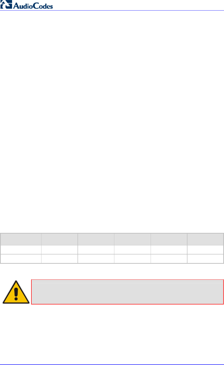
MP252 Multimedia Home Gateway 20 Document #: LTRT-23504
User's Manual
1 Introduction
The MediaPack™ 252 (MP252) is a sophisticated, feature-rich, multimedia home gateway
for broadband networks with multi-play support. With ADSL2+ modem, multiple antenna
wireless LAN connectivity, Digital Enhanced Cordless Telecommunications (DECT)
handsets supporting High Definition (HD) Voice-over-IP (VoIP), and optional battery backup,
this is a true all-in-one gateway for Multi-play services.
The MP252 is ideal for operators, seeking new revenue generators with state-of- the-art
features, such as:
ADSL/ADSL2+ modem, up to 24 Mbps
10/100 Ethernet WAN port (optional connection to cable modem or FTTH ONU)
Optional ADSL WAN backup using 3G USB dongles
HD VoIP telephony and PBX capabilities, including flexible configuration of individual
SIP accounts per DECT extension
Four 10/100 Ethernet LAN ports
High-speed wireless network (802.11 b/g/n), up to 150 Mbps
Router, Firewall, NAT and advanced traffic prioritization mechanisms
2 FXS ports for analog phones and fax machines
Guaranteed Quality of Service (QoS) for IPTV service
Print server and File server, accessible from every computer on the home network
Advanced TR-069 management, interoperable with leading Auto-Configuration Servers
(ACS)
Optional battery backup for up to 4 hours standby
The MP252 is based on AudioCodes’ MP-2xx line of Residential Gateways and AudioCodes
VoIPerfect™ software architecture. The MP252 is interoperable with various softswitches
and supports advanced TR-069 management, working with market leading
Auto-Configuration Servers (ACS). Other management tools, such as a friendly HTTP-based
Web GUI, and Command Line Interface (CLI) are also available.
The MP252 is available in the following models:
Table 1-1: MP252 Available Models
Model ADSL + 4 LAN Wi-Fi 802.11n DECT HD VoIP VoIP 2 FXS USB 2.0
MP252BW √ √ - √ 1
MP252WDNB √ √ √ √ 3
Note: All DECT and PBX--related functionalities are supported only by the
MP252WDNB.
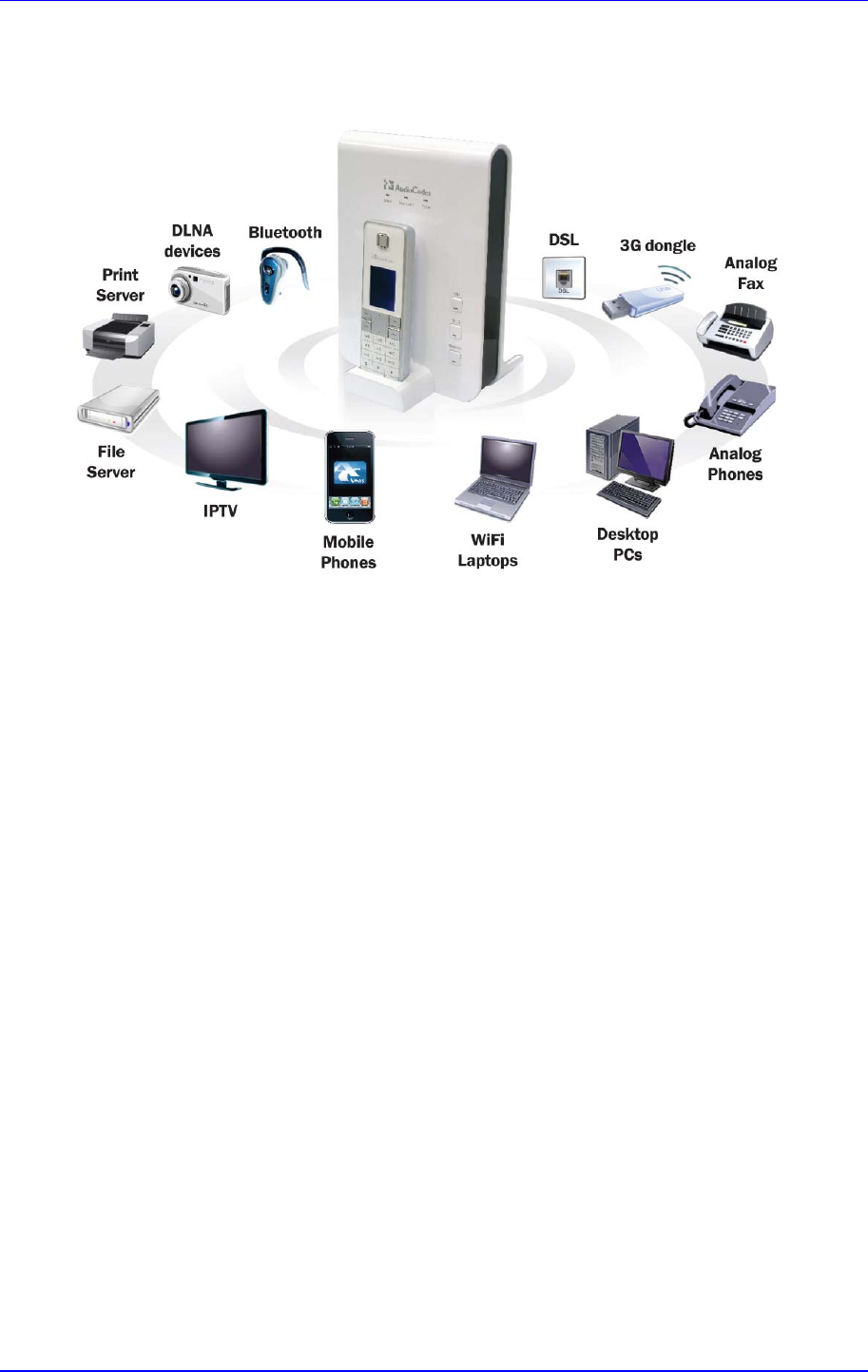
MP252 Multimedia Home Gateway 1. Introduction
Version 3.4.0 21 June 2011
The figure below illustrates the typical applications supported by MP252:
Figure 1-1: MP252 Typical Application

MP252 Multimedia Home Gateway 22 Document #: LTRT-23504
User's Manual
2 Package Contents and Prerequisites
The MP252 is shipped with the following items:
1 x RJ-11 telephone cable
1 x RJ-45 Ethernet cable
12V AC/DC power adaptor (use only supplied)
DECT handset and cradle
Make sure that all these items are included. If any items are missing, contact your sales
representative.
The following prerequisites are required (not supplied by AudioCodes):
A broadband Internet connection
ADSL cable (if required)
Analog telephones
Additional RJ-11 telephone cable (if required)
Additional RJ-45 Ethernet cables (if required)
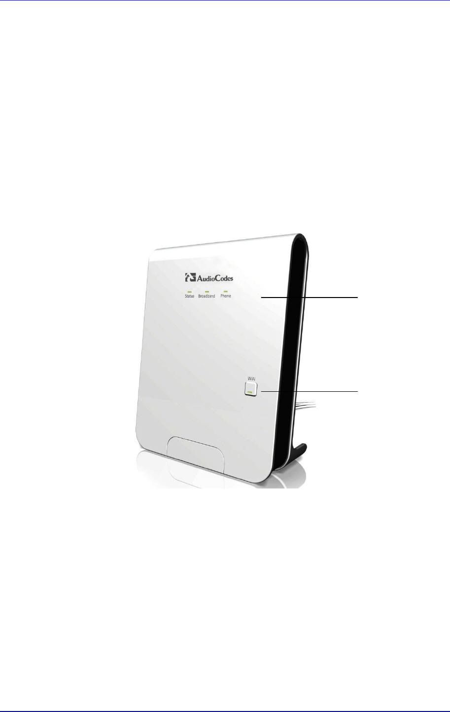
MP252 Multimedia Home Gateway 3. Hardware Description
Version 3.4.0 23 June 2011
3 Hardware Description
This section describes the physical description and cabling of the MP252. This includes both
models (i.e., MP252BW and MP252WDNB).
3.1 Physical Description
The MP252 provides ports, buttons, and LEDs on its front and rear panels.
3.1.1 Front Panel
The front panel provides LEDs for displaying various operating status and button(s) for
activating various features such as Wi-Fi. For more information on the LEDs, see Section
3.1.1.2 on page 25. For more information on the buttons, see Section 3.1.1.1 on page 24.
The figures below display the front panels of the MP252 models.
Figure 3-1: Front Panel of MP252BW
WiFi Button
LEDs
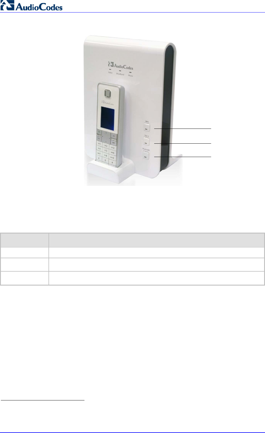
MP252 Multimedia Home Gateway 24 Document #: LTRT-23504
User's Manual
Figure 3-2: Front Panel of MP252WDNB
3.1.1.1 Front-Panel Buttons Description
The button(s) on the front panel are described in the table below:
Table 3-1: Front-Panel Buttons Description
Label Description
WiFi Activates or deactivates Wi-Fi connectivity (802.11 b/g/n).
Dect1 Registers the handset to the MP252 base unit.
Bluetooth2 Currently not supported.
1
This button is available only on the MP252WDNB model.
2
This button is available only on the MP252WDNB model.
WiFi Button
DECT Button
Bluetooth
Button
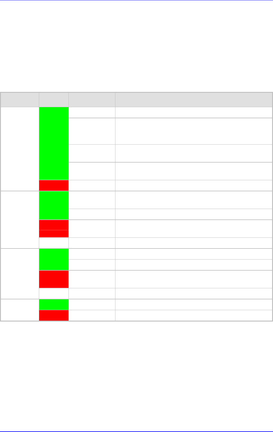
MP252 Multimedia Home Gateway 3. Hardware Description
Version 3.4.0 25 June 2011
3.1.1.2 Front-Panel LEDs Description
The LEDs on the front panel are described for general functionality and for the Automatic
Dialer feature.
3.1.1.2.1 General Description
The general description of the MP252 front-panel LEDs are described in the table below:
Table 3-2: Front-Panel LEDs Description
LED Color State Description
On Device start-up successful
Slow Blinking Software upgrade in progress.
Note: During software upgrade, the Broadband and Phone
LEDs also blink green.
Slow Blinking Battery backup is in use and there is no power from the AC
electrical outlet.
Green
Fast Blinking Battery is low and there is no power from the AC electrical
outlet.
Status
Red On Reboot (automatic, by default) or indicates a problem
On WAN port is successfully connected and IP address
acquired successfully
Green
Blinking Software upgrade in process
Red On WAN IP address has not yet been acquired from the ISP
(i.e. in the process of acquiring or has failed to acquire).
Broadband
- Off WAN Ethernet cable is not connected – no WAN link
On All configured phones are registered to the Proxy server
Green
Blinking Software upgrade in process
Red On At least one of the phones failed to register to the Proxy
server
Phone
- Off No Proxy server is configured
Green On Wi-Fi is enabled and active
WiFi
Red Off Wi-Fi is disabled
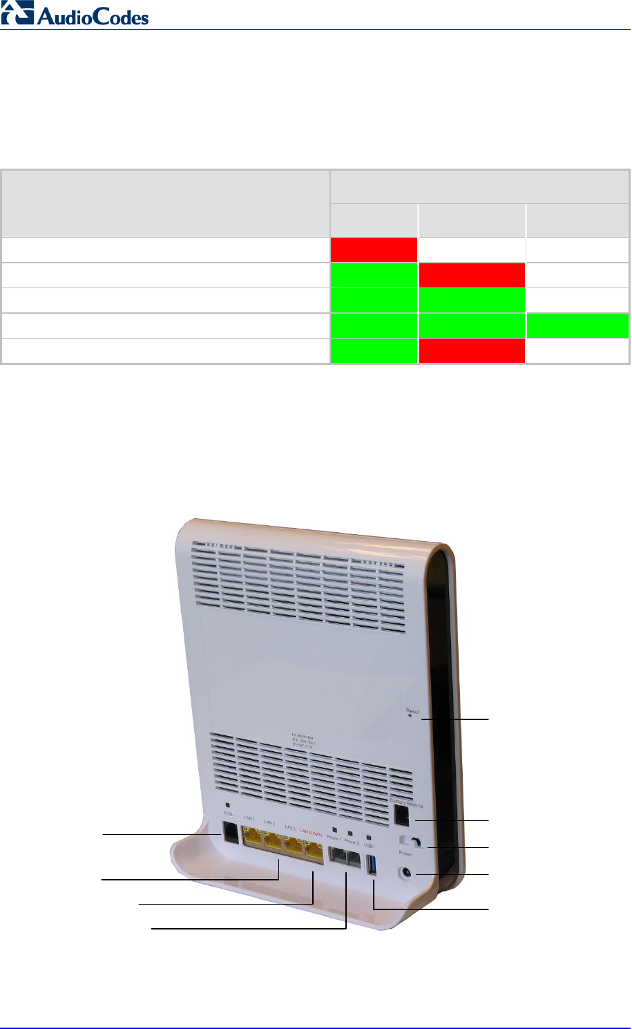
MP252 Multimedia Home Gateway 26 Document #: LTRT-23504
User's Manual
3.1.1.2.2 Automatic Dialer Feature
The table below describes the front-panel LEDs behavior when the Automatic Dialer feature
is used (described in detail in Section 7.2).
Table 3-3: Front-Panel LED Descriptions for Automatic Dialer Feature
LED Stage
Status Broadband Phone
During boot Red Off Off
Before WAN physical link detection Green Blinking Red Off
During automatic dialer operation Green Blinking Green Off
Automatic dialer success Green Green Green*
Automatic dialer failure Green Red Off
* The Phone LED lights green only after MP252 connects to the Internet, downloads its
configuration file, and then registers to the VoIP service.
3.1.2 Rear Panel
The rear panel provides the ports for connecting the various interfaces. The figures below
display the rear panels of the MP252 models.
Figure 3-3: Rear Panel of MP252BW
Reset Button
Battery Backup Port
Power Plug
FXS Phone Ports
LAN/WAN Port
ADSL Port
LAN Ports
USB Plug
Power Button
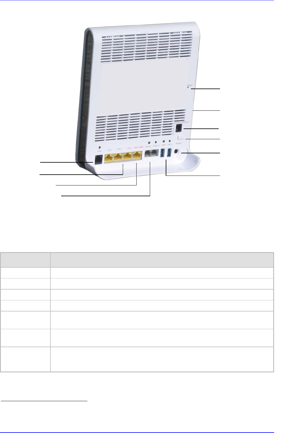
MP252 Multimedia Home Gateway 3. Hardware Description
Version 3.4.0 27 June 2011
Figure 3-4: Rear Panel of MP252WDNB
3.1.2.1 Rear-Panel Port Description
The ports of the rear panel are described in the table below:
Table 3-4: Rear-Panel Ports Description
Label Description
ADSL RJ-11 port for connecting ADSL/ADSL2+ modem (up to 24 Mbps)
LAN 3 x RJ-45 10/100Base-T Ethernet LAN ports
LAN/WAN 1 x RJ-45 10/100Base-T Ethernet LAN or Ethernet WAN port
Phone 2 x RJ-11 FXS ports for connecting analog phones and fax machines
USB3 USB Type A port for print or file servers, or for optional WAN backup using a 3G USB
dongle
Power Power plug for connecting the supplied AC/DC power adapter. A button is located
above this port to switch on the MP252.
Battery Backup Port for connecting an optional battery backup, providing up to four hours standby
power. (The external battery backup system connects to this port and the Power
plug using a splitter cable.)
3
The MP252WDNB model provides two USB ports in this location.
Reset Button
Battery Backup Port
Power Plug
USB (3) Plug
FXS Phone Ports
LAN/WAN Port
ADSL Port
LAN Ports USB (1 & 2)
Plugs
Power Button
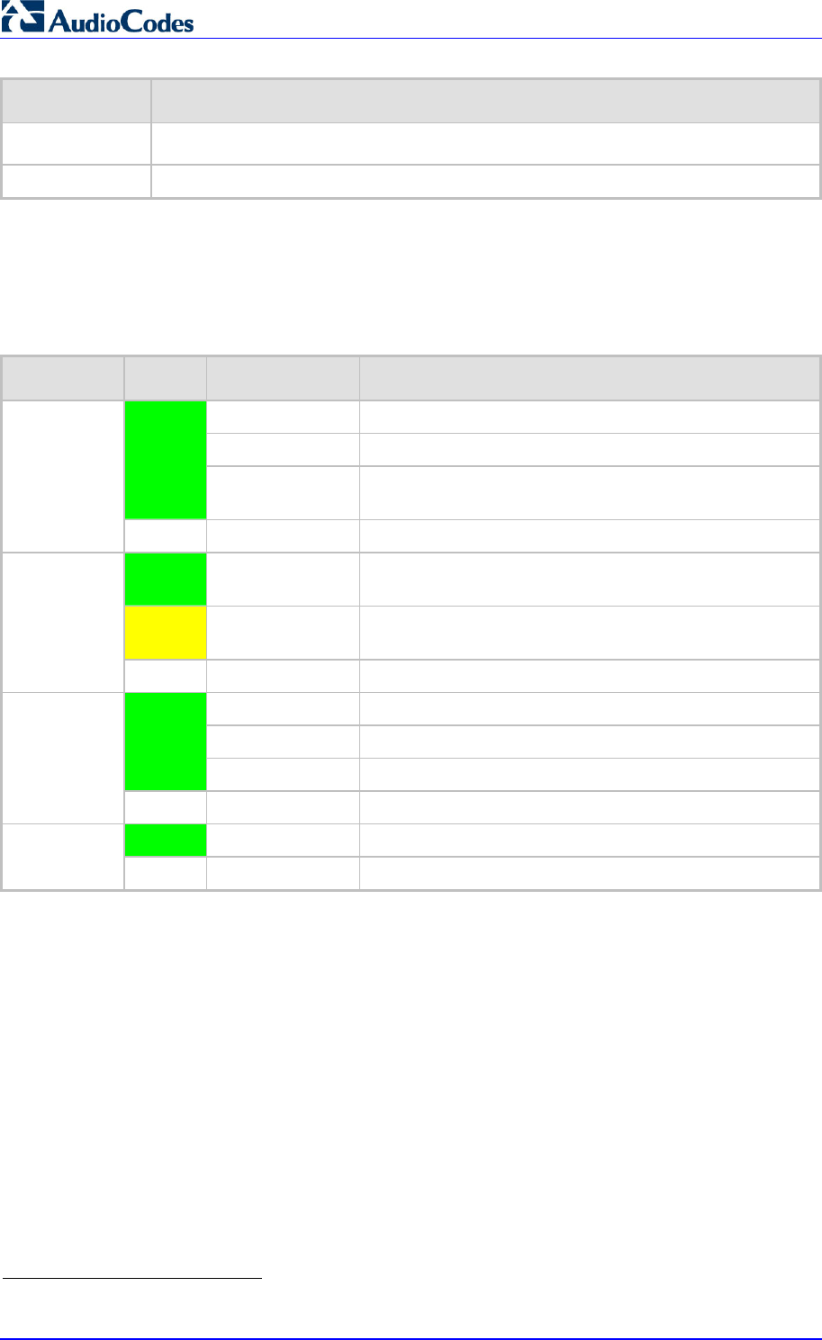
MP252 Multimedia Home Gateway 28 Document #: LTRT-23504
User's Manual
Label Description
USB34 USB port (located on the side panel, as shown in Figure 3-4).
Reset Reset pin button for resetting the MP252.
3.1.2.2 Rear-Panel LEDs Description
The LEDs on the rear panel are described in the table below:
Table 3-5: Rear-Panel LEDs Description
LED Color State Description
On ADSL physical link is up
Slow Blinking ADSL link is synchronizing
Green
Fast Blinking ADSL attempting to train (establishing a connection with
the Internet Service Provider)
ADSL
- Off No physical ADSL link
Green Blinking LAN / WAN connection sending / receiving data at 100
Mbps
Yellow Blinking LAN / WAN connection sending / receiving data at 10
Mbps
LAN / WAN
- Off No LAN / WAN traffic or Ethernet cable is disconnected
On Phone is off-hook
Slow Blinking Phone is ringing
Green
Fast Blinking MP252 is currently being upgraded
Phone
- Off Phone is on-hook and not ringing
Green On USB device is connected
USB
- Off No USB device is connected
4
This USB port is available on the MP252WDNB model.
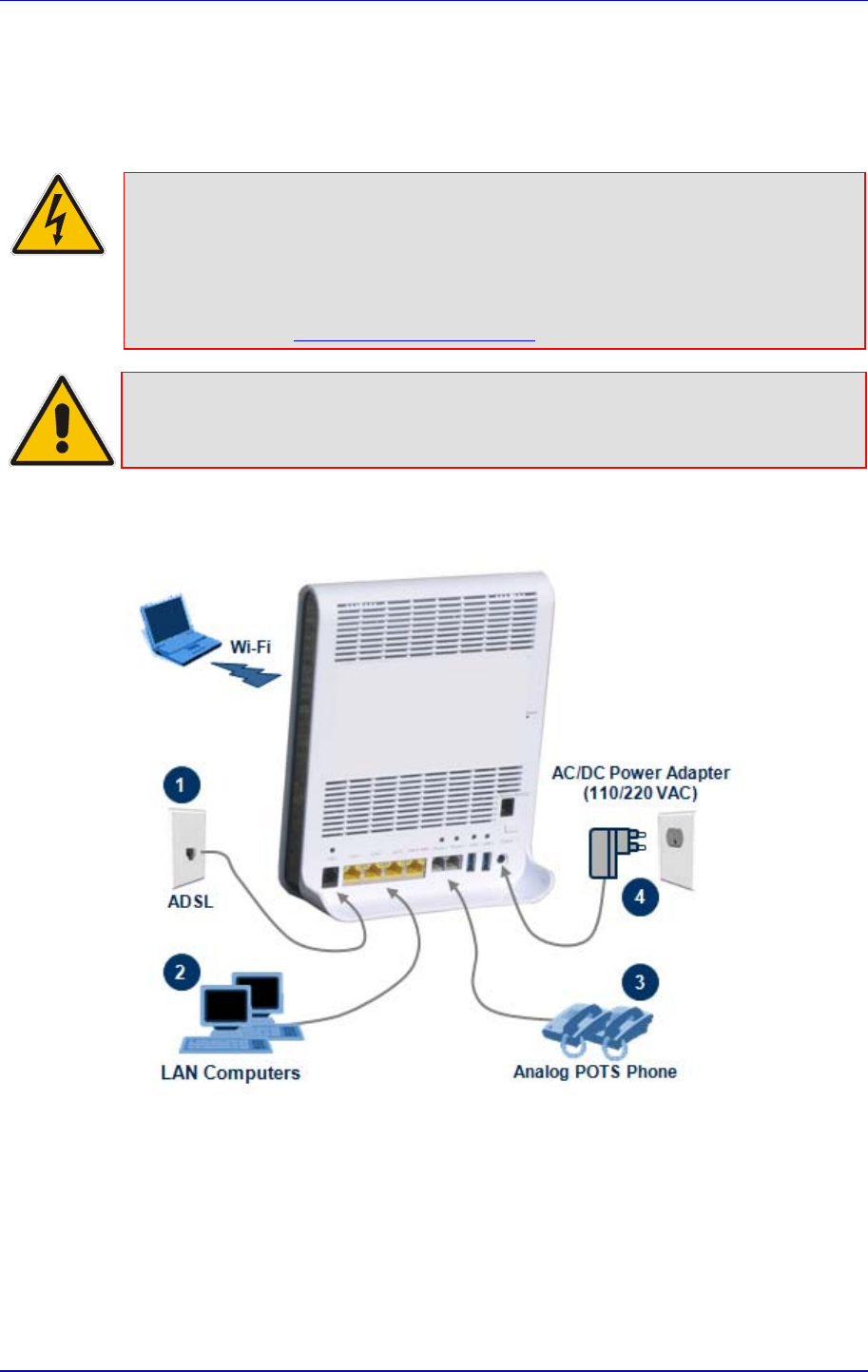
MP252 Multimedia Home Gateway 3. Hardware Description
Version 3.4.0 29 June 2011
3.2 Cabling
The procedure below describes the cabling of the MP252.
Warning:
• Use only the AC/DC power adapter supplied with MP252. Do not use
any other power adapter.
• Ensure that the VAC ratings match.
• Ensure that you have read the MP252 Regulatory Information, obtained
from www.audiocodes.com/library.
Note: The cabling procedures for the MP252 models are identical and therefore, no
distinction is made between the models in this section. However, for
convenience, this section uses the MP252WDNB model as an example.
The figure below displays a summary of the cabling procedures.
Figure 3-5: Cabling MP252
MP252 Multimedia Home Gateway 30 Document #: LTRT-23504
User's Manual
¾ To cable MP252:
1. Connect MP252 to the Internet. The cabling depends on the Internet connection:
• ADSL: connect the ADSL port (located on the rear panel and labeled ADSL) to the
telephone socket, using an RJ-11 telephone cable.
• WAN Ethernet: connect the LAN4/WAN port (located on the rear panel and
labeled LAN 4/WAN) to an external modem, using a CAT-5 Ethernet cable.
Note: Use minimum 26 AWG wire for cabling the ADSL port to the public switched
telephone network (PSTN).
2. Connect the LAN Ethernet ports (labeled LAN 1 - 4) to your LAN computers, using
RJ-45 CAT-5 Ethernet cables.
3. Connect the telephone ports (labeled Phone 1 - 2) to analog telephones, using RJ-11
telephone cables.
4. Connect MP252 to a standard 110/220 VAC electrical wall outlet, using the supplied
AC/DC power adapter.
When MP252 is powered on, the Status LED is lit. After initialization completes (about two
minutes), this LED changes from red to green. If no power is received by
MP252, press the Power button located on the rear panel to switch it on.
3.3 Mounting
You can place MP252 on a desktop or mount it on a wall. For desktop mounting, MP252
provides integrated rubber feet on its base so that it sits firmly on a desktop. Alternatively,
you can hang your MP252 on a wall, using the supplied MP252 wall-mounting bracket, as
described in this section.
Wall mounting consists of the following main procedural stages:
Preparing the mounting screws on the wall
Hanging the mounting bracket on the wall
Attaching MP252 to the mounting bracket
Before you begin, ensure that you have the following items:
Wall-mounting bracket (supplied)
2 x screws
2 x wall anchors
Screwdriver
Note: When choosing a wall on which to mount MP252, consider cable limitations and
wall structure.
¾ To wall-mount MP252:
1. Prepare the wall-mounting screws:
a. Drill two holes in the wall according to the wall-mounting bracket dimensions. The
vertical distance between the holes should be 83 mm (3.27 inches).
b. Insert a wall anchor into each hole.
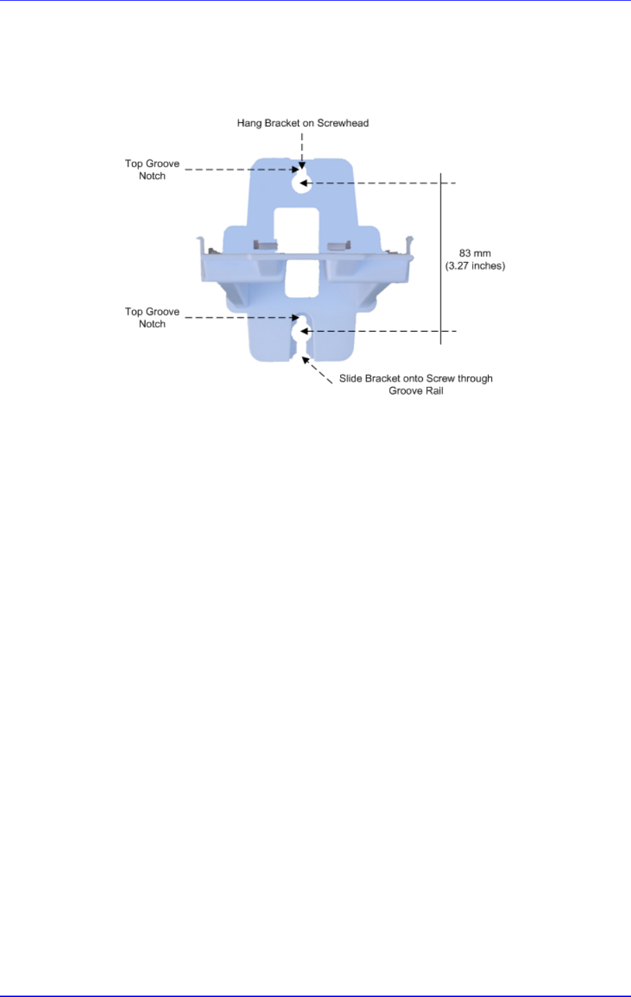
MP252 Multimedia Home Gateway 3. Hardware Description
Version 3.4.0 31 June 2011
c. Using a screwdriver, drive screws of the appropriate size into the anchors, leaving
approximately 4 mm (0.16 inches) of the screw head jutting out. This protrusion will
allow you to hang the mounting bracket on the screw head.
Figure 3-6: MP 252 Wall Mount Bracket
2. Hang the mounting bracket on the wall screws:
a. Gently slide the mounting bracket onto the lower screw so that the screw enters the
bracket's bottom screw groove rail. As you lower the bracket onto the screw,
ensure that the upper screw fits into the bracket's top screw groove.
b. Gently pull down on the mounting bracket so that both screw heads sit firmly and
securely in the top notch of the screw grooves.
3. Attach MP252 to the wall-mounting bracket:
a. Three slits at the base (bottom) of MP252 are covered by rubber caps. Remove
these caps.
b. With its rear panel facing the mounting bracket, hold MP252 at an angle and slide
the base of MP252 under the two latches located on the mounting bracket.
c. Align the three slits on the MP252 base with the three protruding humps located on
the front of the mounting bracket. Align the clip holes on either side of MP252 with
the clips on the mounting bracket.
d. While gently pressing down on MP252, press the clips inwards so that the clips
snap into the base of MP252.

MP252 Multimedia Home Gateway 32 Document #: LTRT-23504
User's Manual
Figure 3-7: Attaching Phone Base to Wall Mount
If for any reason, you want to remove MP252 from the wall, follow the procedure below:
¾ To dismount MP252 from the wall:
1. Press the mounting bracket clips inwards.
2. Lift the MP252 base off the mounting bracket.

Part I
Gateway Configuration
Part I describes the configuration of the MP252 router and VoIP functionality analog, and
includes the following chapters:
Setting up an Internet Connection
Using MP252's Web Interface
Configuring VoIP Parameters
Connecting MP252 to a VoIP Service Provider
Making VoIP Calls
Quality of Service (QoS)
LAN Connection
WAN Connection
Editing Network Connections and Advanced Configuration
VLAN Settings
LAN-WAN Bridge Settings
Remote MP252 Management
Security
Advanced Settings
System Monitoring
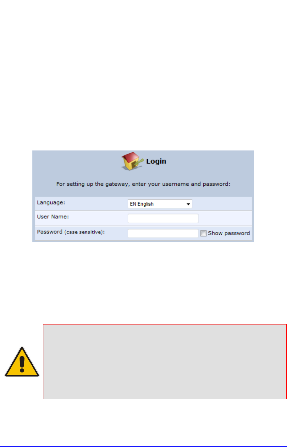
Version 3.4.0 35 July 2011
MP252 Multimedia Home Gateway 4. Getting Started with the Web Interface
4 Getting Started with the Web Interface
The MP252 embedded Web server (Web interface) provides a user-friendly Web-based
management tool that allows you to configure and monitor MP252. This chapter describes
how to access, navigate in, and configure parameters with the Web interface.
4.1 Logging in to the Web Interface
The procedure below describes how to log in to the MP252 Web interface.
¾ To log in to the MP252 Web interface:
1. Connect a PC directly to the LAN port (labeled LAN 1) of the MP252.
2. On your PC, open a Web browser (e.g., Internet Explorer) and in the URL field, enter
http://mp252.home (or 192.168.2.1). If your MP252 is already connected to the
network and you know its IP address, then enter its IP address instead. The ‘Login’
screen appears:
Figure 4-1: Login Screen
3. From the ‘Language’ drop-down list, select the desired language for the Web graphical
user interface (GUI) display.
4. In the 'User Name' and 'Password' fields, define a login username and password,
respectively. This is applicable only if this is your first time that you are logging in to the
Web interface. If you have logged in before, then enter the username and password that
you defined previously.
5. Click Continue; the ‘Quick Setup’ screen appears, allowing you to quickly set up an
Internet connection (as described in Chapter 5 on page 50).
Notes:
• The default username and password is "admin" (case-sensitive).
• If you wish to view the entered password (instead of asterisks), then select
the ‘Show password’ check box.
• You can later change the username and password as described in Section
4.4 on page 323.
• If the Web interface is inactive for 15 minutes after logging in, the ‘Login’
screen appears again, prompting you to re-login.
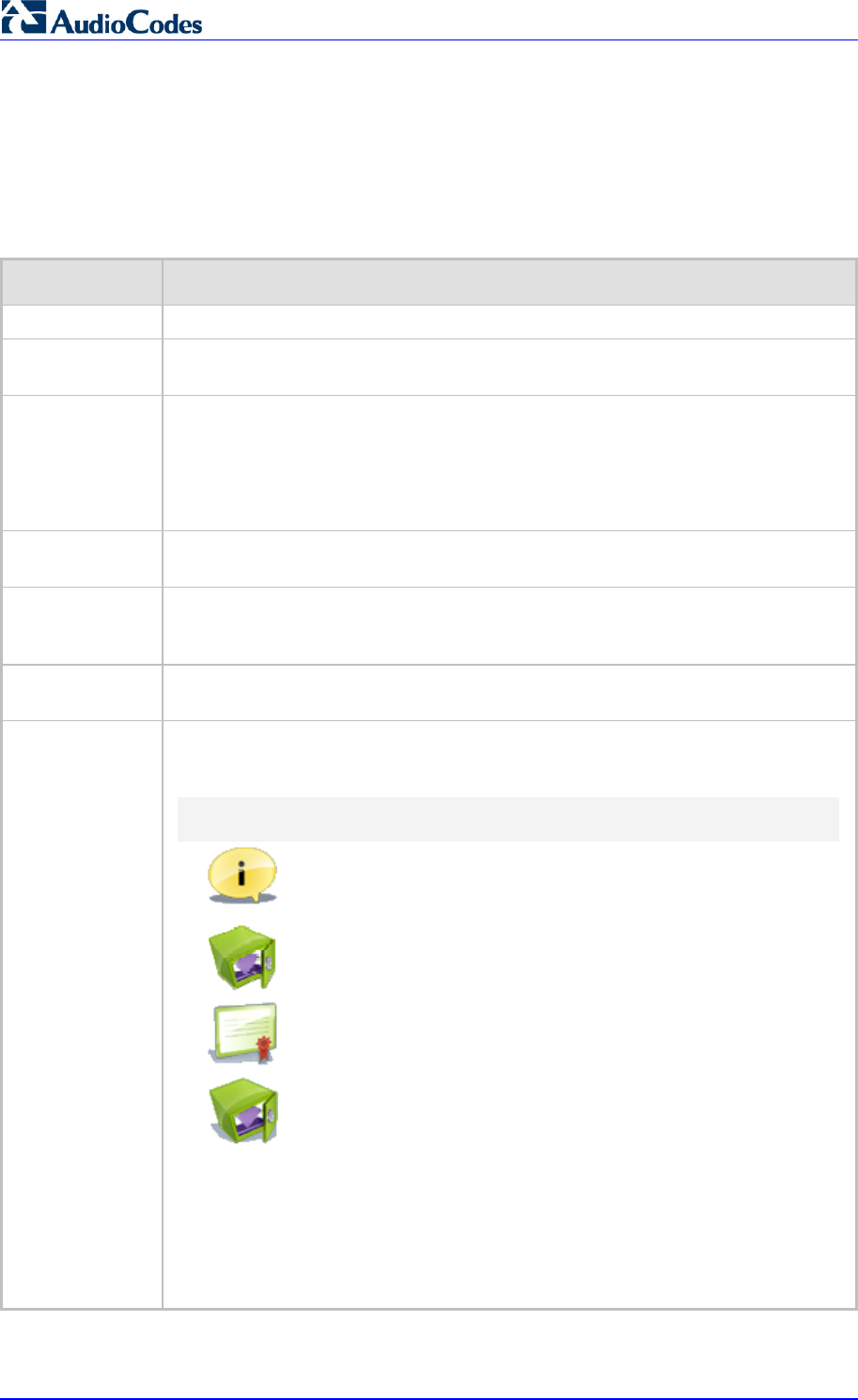
MP252 Multimedia Home Gateway 36 Document #: LTRT-23504
User's Manual
4.2 Menu Bar Description
The Web interface screens are conveniently grouped into related themes under specific
menus. These menus are located in the menu bar. The table below describes these menus.
Table 4-1: Menu Description
Menu Description
Home Displays the Map View (refer to Section 5 on page 50).
Quick Setup Displays the 'Quick Setup' screen for quickly setting up an Internet connection with
MP252 (see Section 7.1 on page 57).
Network
Connections Displays the 'Network Connections' screen for configuring network connections:
LAN (see Chapter 12.2 on page 143)
WAN (see Chapter 12 on page 123)
VLANs (see Chapter 12.4 on page 173)
LAN-WAN bridging (see Section 12.5 on page 180)
Security Displays the 'Security' screen for configuring security-related features such as
Website restrictions (see Chapter 14 on page 217).
Voice Over IP Displays the 'Voice Over IP' screen for configuring the VoIP parameters to use
MP252's VoIP functionality to place and receive calls over the Internet using a
standard telephone set and DECT handset (see Chapter8 on page 70).
QoS Displays the 'Quality Of Service' screen for configuring Quality of Service (QoS) fo
r
MP252 (see Chapter 11 on page 105).
Advanced Displays the 'Advanced' screen for configuring system parameters (e.g., DHCP
server and DNS) and for administrative functions (e.g., changing password, setting
date and time, and upgrading the system).
Icon Name Description
About MP252 Displays technical information about MP252,
including version number (see Section 18.1
on page 302).
Backup and
Restore Backup user and system data (see Section
18.2 on page 303).
Certificates Manages digital certificates (see Section 13.3
on page 192).
Configuration
File
Loads the Configuration File to MP252 (see
Section 18.4 on page 308).
Note: You can hide the Configuration File
icon, by running the following CLI command in
a Telnet session with MP252: rg
_
conf
_
set
rmt_config/hide_config_file_page
1. This is useful, for example, in scenarios
where you want to prevent a user accessing
the Web interface to change the configuration
file.
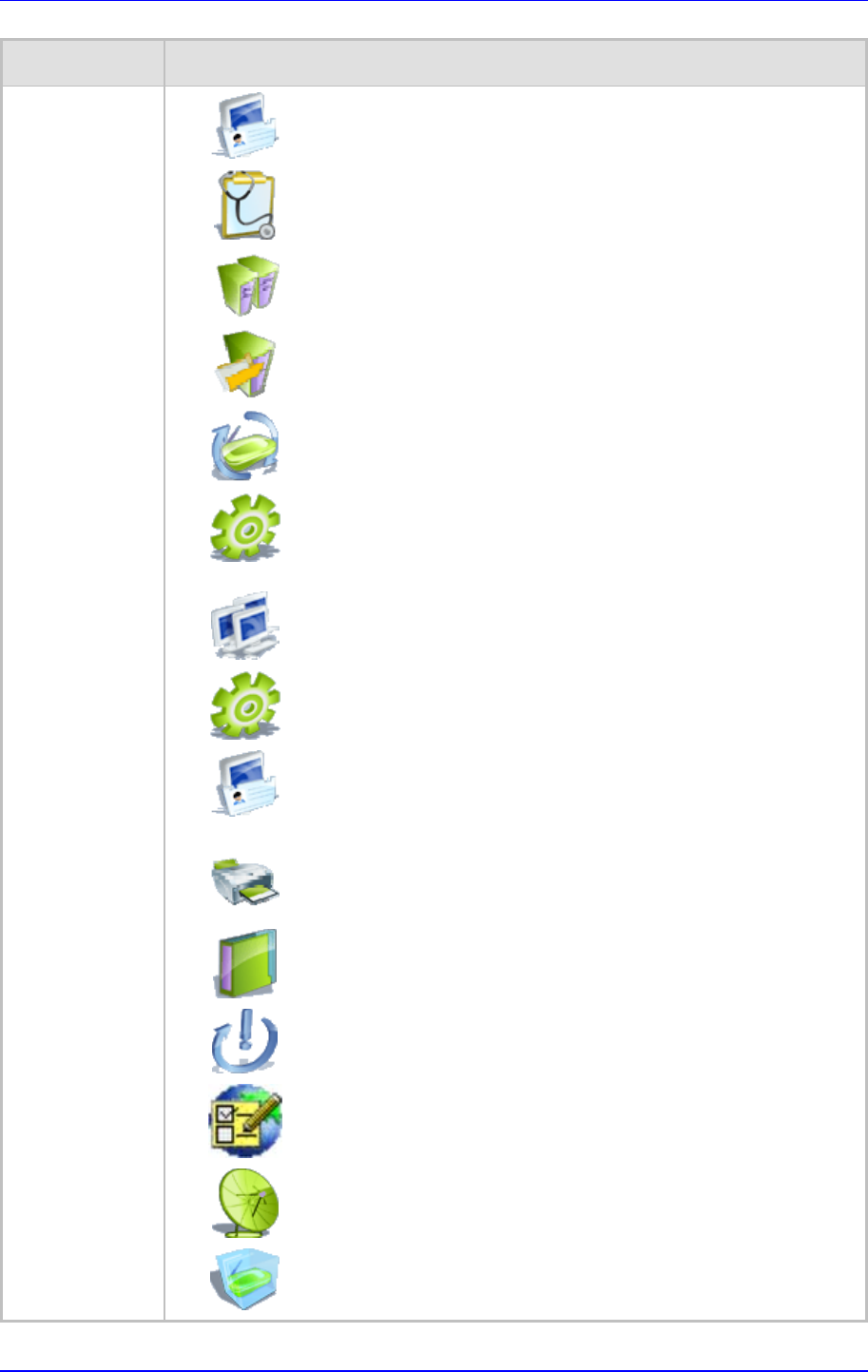
MP252 Multimedia Home Gateway 4. Getting Started with the Web Interface
Version 3.4.0 37 June 2011
Menu Description
DNS Server Alias a dynamic IP address to a static
hostname (see Section 15.2 on page 249).
Diagnostics Performs networking diagnostics (see Section
19.1 on page 326).
Disk
Management Manages different disks connected to MP252
(see Section 17.2 on page 265).
File Server Creates a file server on MP252 (see Section
17.1 on page 263).
Firmware
Upgrade
Upgrades the MP252 firmware (see Section
18.5 on page 315).
IP Address
Distribution
Modifies the DHCP server for each LAN
device and displays a list of DHCP clients in
the local network (see Section 15.1 on page
243).
Network
Objects
Defines groups of LAN devices for system
rules (see Section 4.5.2 on page 46).
PPPoE Relay Enables PPPoE relay on MP252 (see Section
15.5 on page 254).
Personal
Domain Name
(Dynamic
DNS)
Displays and modifies the DNS hosts table
(see Section 15.2 on page 249).
Print Server Shares a LAN printer (see Section 17.3 on
page 279).
Protocols Manages protocols (see Section4.5.3 on
page 47).
Reboot Restarts MP252 (see Section 18.6 on page
321).
Regional
Settings
Modifies the regional settings (see Section
8.10 on page 98).
Remote
Administration Configures remote administration privileges
(see Section 13.2 on page 189).
Restore
Factory
Settings
Restores default factory settings (see Section
18.8 on page 325).
MP252 Multimedia Home Gateway 38 Document #: LTRT-23504
User's Manual
Menu Description
Routing Manages routing policies (see Section 15.4
on page 253).
Scheduler Defines time segments for system rules (see
Section 4.5.1 on page 43).
Simple
Network
Management
Protocol
(SNMP)
Configures MP252's SNMP agent (see
Section 13.2 on page 189).
System
Settings Modifies administrator settings, including the
MP252 host name (see Section 15.5 on page
254).
Time Settings Configures the local date and time (see
Section 18.2 on page 303).
Universal Plug
and Play
Configures Universal Plug-and-Play (UPnP)
parameters (see Section 16.1 on page 257).
Users Configures Users (see Section 4.4 on page
40).
WINS Server Registers host names and IP addresses of
WINS clients (see Section Error! Reference
source not found. on page Error!
Bookmark not defined.).
System
Monitoring Displays the 'System Monitoring' screen for viewing various statuses such as
network and traffic statistics (see Chapter 16 on page 257).
Logout Logs off the MP252 Web interface.
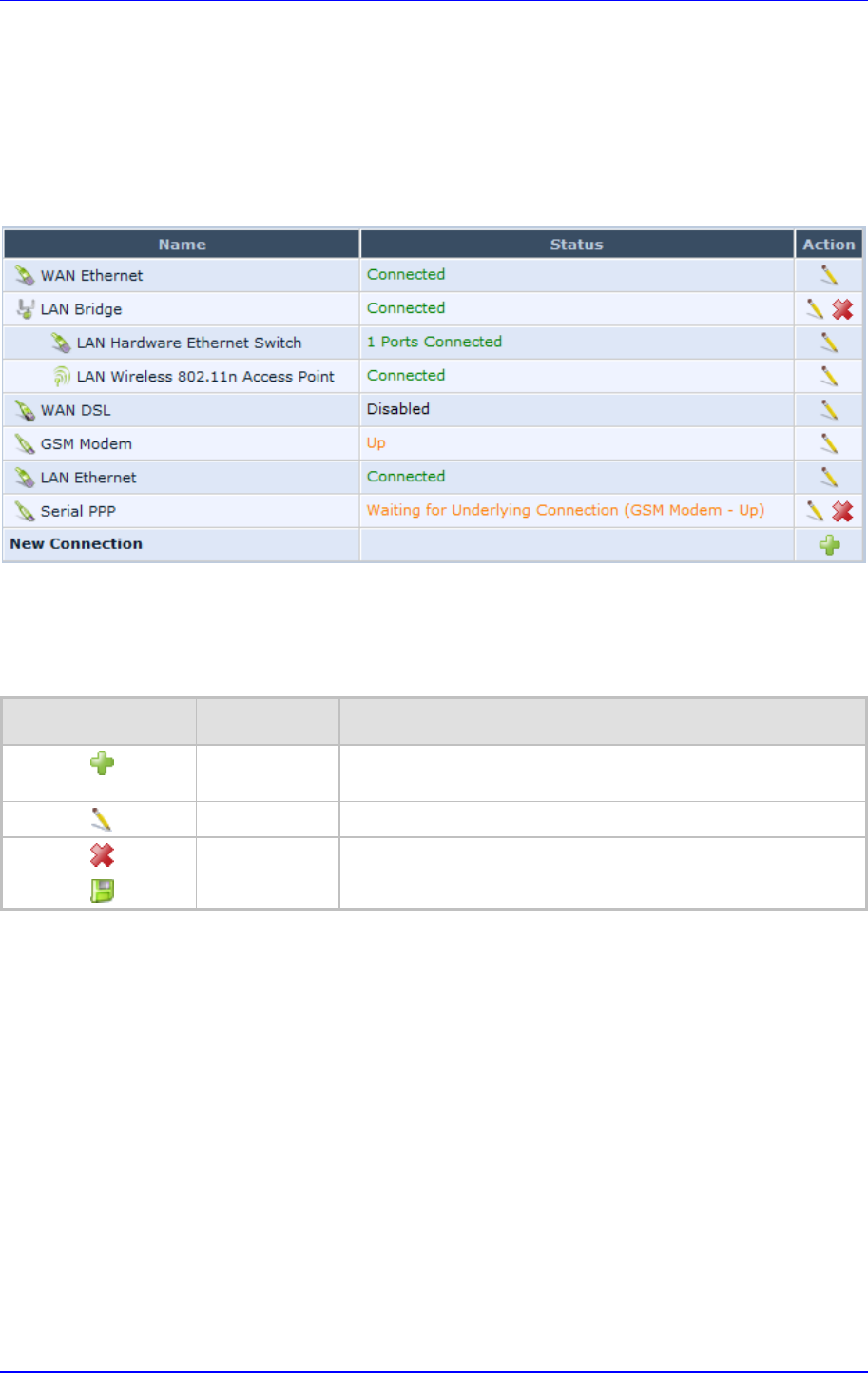
MP252 Multimedia Home Gateway 4. Getting Started with the Web Interface
Version 3.4.0 39 June 2011
4.3 Managing Tables
Tables appear throughout the Web interface for configuring MP252. This section describes
the how to use these tables to configure MP252.
The figure below displays a typical table in the Web interface:
Figure 4-2: Typical Table Structure
Each table row denotes an entry in the table. The table also provides 'Action' icons for
performing various tasks. These icons are described in the table below.
Table 4-2: Table Action Icons Description
Action Icon Name Description
New Adds a new row to the table or opens another screen for
adding an entry.
Edit Modifies a row entry in the table.
Remove Deletes a row entry in the table.
Download Downloads a file to a folder on your computer.
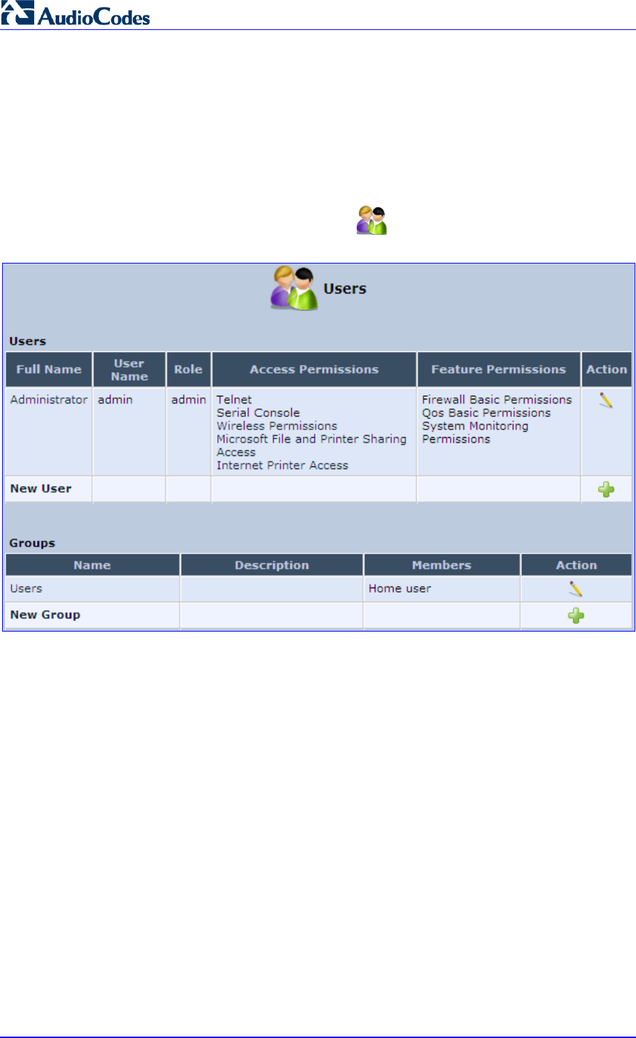
MP252 Multimedia Home Gateway 40 Document #: LTRT-23504
User's Manual
4.4 Configuring Users
The 'Users' screen allows you to add new users and assign login usernames and passwords.
You may also group users according to your preferences. The default user is "Administrator"
with "admin" (case-sensitive) as the username and password.
¾ To configure users:
1. In the 'Advanced' screen, click the Users icon; the 'Users' screen appears.
Figure 4-3: Users Screen
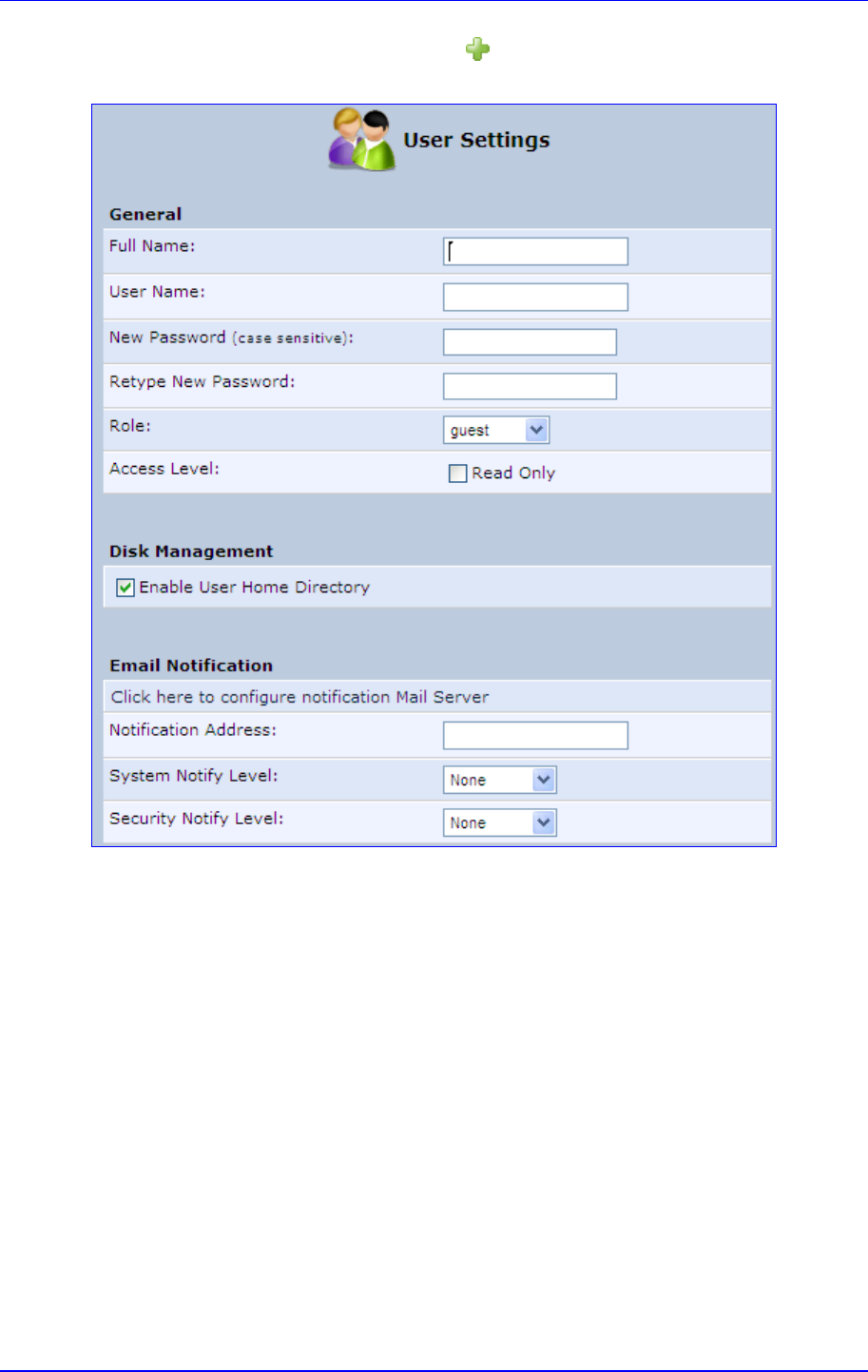
MP252 Multimedia Home Gateway 4. Getting Started with the Web Interface
Version 3.4.0 41 June 2011
2. In the Users table, click the New User icon; the 'Users Settings' screen appears.
Figure 4-4: Users Settings Screen
3. Add a new user by configuring the following fields:
a. Full Name: Enter a remote user's full name.
b. User Name: Enter a user name to access your home network.
c. New Password: Enter a new password for the remote user. If you do not want to
change the remote user's password leave this field empty.
d. Retype New Password: If a new password was assigned, enter it again to verify
correctness.
e. Role: User’s role indicating privilege level, where “admin” possesses all privileges.
f. Access Level – Read Only: Select this check box if you want this user to have
read-only privileges.
g. Disk Management: By default, this option is selected. When activated, it creates a
directory for the user in the 'Home' directory of the system storage area. This
directory is necessary when using various applications such as the mail server.
h. Email Notification: You can use email notification to receive indications of system
events for a predefined severity classification. The available types of events are
'System' or 'Security' events. The available severity of events is 'Error', 'Warning'
and 'Information. If the 'Information' level is selected, the user receives notification
of the 'Information', 'Warning' and 'Error' events. If the 'Warning' level is selected,
the user receives notification of the 'Warning' and 'Error' events etc.
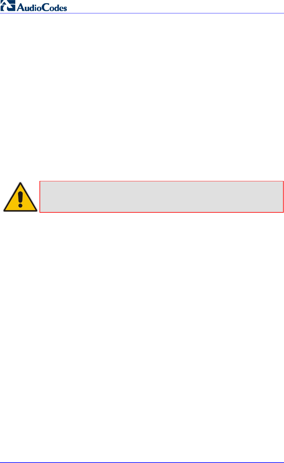
MP252 Multimedia Home Gateway 42 Document #: LTRT-23504
User's Manual
♦ Click here to configure notification mail server: This opens the ‘System
Settings’ screen (see Section 15.5 on page 254) where you can define an
outgoing mail server.
♦ Notification Address: user’s email address.
♦ System Notify Level: By default, the 'None' option is selected, which means
that MP252 does not send notifications to a remote host. To activate the
feature, select one of the following notification types:
9 Error
9 Warning
9 Information
♦ Security Notify Level: The remote security notification level can be one of
the following:
9 None
9 Error
9 Warning
9 Information
4. Click OK.
Note: Modifying any of the user parameters prompts the connection associated with
the user to terminate. For changes to take effect, you should activate the
connection manually after modifying user parameters.
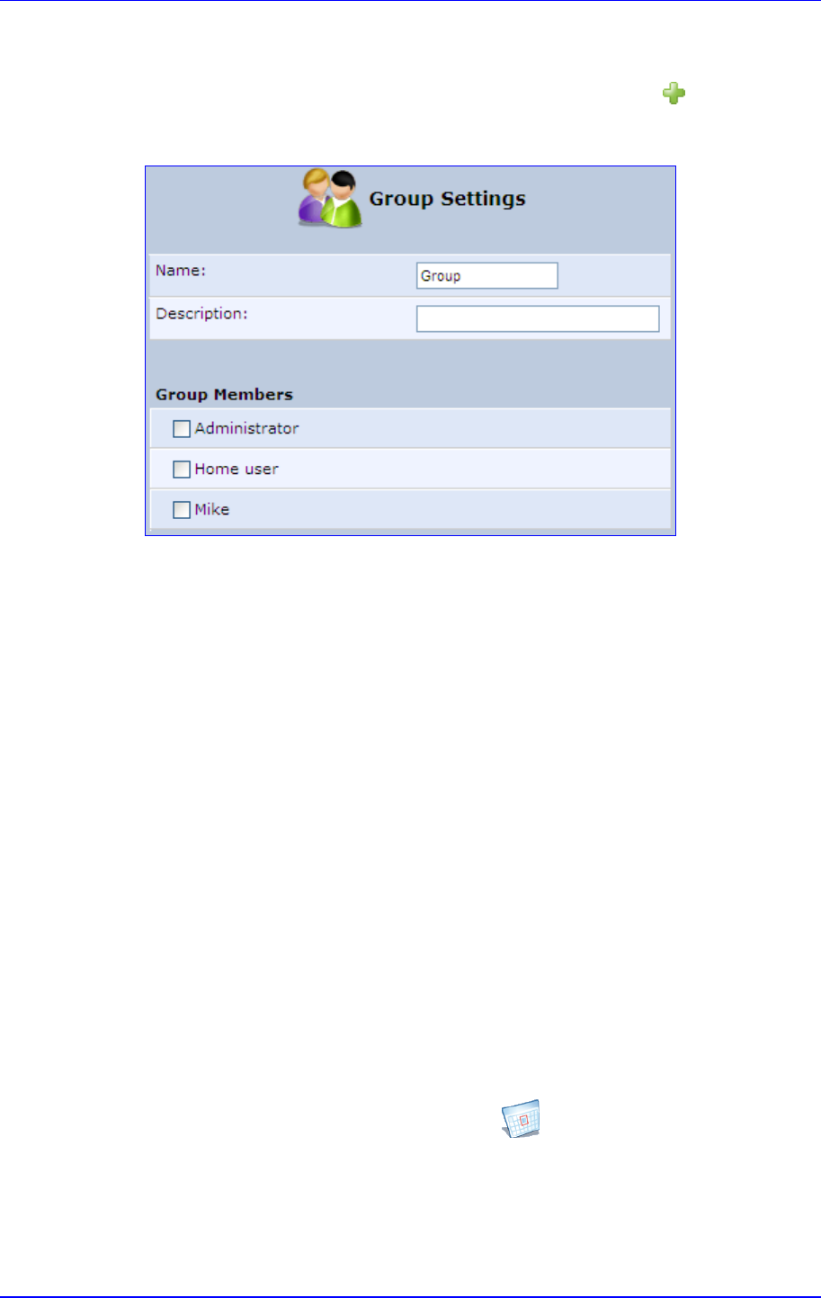
MP252 Multimedia Home Gateway 4. Getting Started with the Web Interface
Version 3.4.0 43 June 2011
¾ To configure user groups:
1. In the 'Users' screen, under the Groups group, click New Group icon; the 'Group
Settings' screen appears.
Figure 4-5: Group Settings Screen
2. In the 'Name' field enter a name for the group.
3. In the 'Description' field, enter a brief description of this group.
4. In the 'Group Members' list, select the users that you want to assign to this group.
5. Click OK.
4.5 Defining Associated Elements
You can define certain elements and then use them later when configuring various features
throughout the Web interface. This is very convenient in that it eliminates the need to
re-configure the same element, especially if used in multiple configuration areas. These
elements include the following:
Scheduler Rules – see Section 4.5.1 on page 43
Network Objects – see Section 4.5.2 on page 46
Protocols – see Section 4.5.3 on page 47
4.5.1 Defining Scheduler Rules
Scheduler rules are used for limiting the activation of firewall rules to specific time periods,
specified in days of the week, and hours.
¾ To define a Rule:
1. In the 'Advanced' screen, click the Scheduler icon; the 'Scheduler Rules' screen
appears.
Figure 4-6: Scheduler Rules Screen
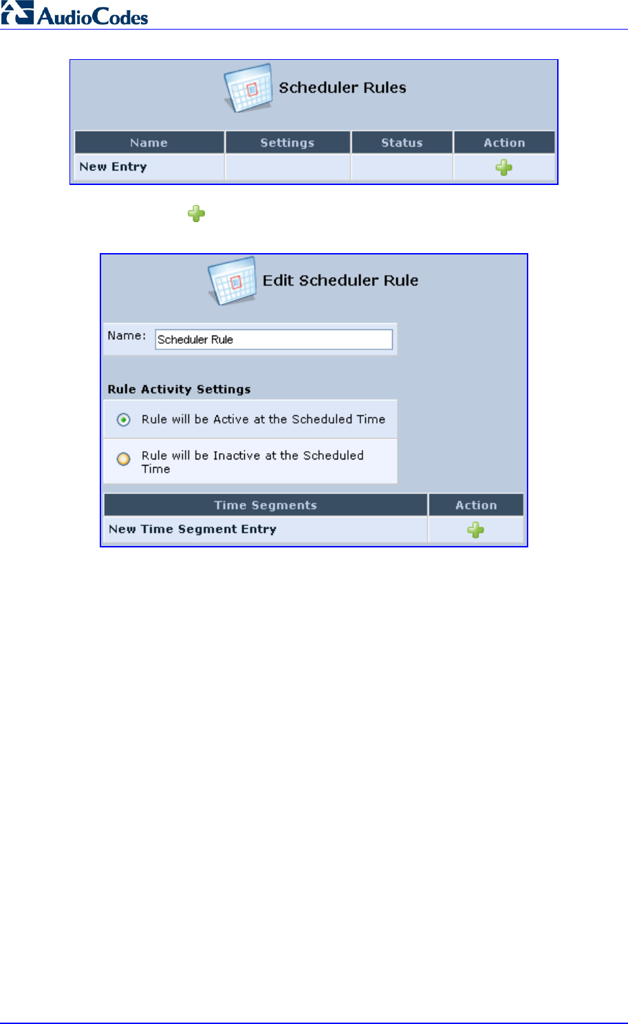
MP252 Multimedia Home Gateway 44 Document #: LTRT-23504
User's Manual
2. Click the New icon; the 'Edit Scheduler Rule' screen appears.
Figure 4-7: Edit Scheduler Rule Screen
3. In the 'Name' field, specify a name for the scheduler rule.
4. Under the Rule Activity Settings group, specify if the rule is active or inactive during
the designated time period, by selecting the appropriate check box.
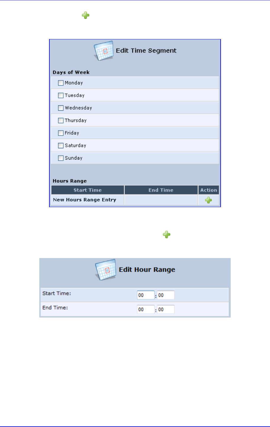
MP252 Multimedia Home Gateway 4. Getting Started with the Web Interface
Version 3.4.0 45 June 2011
5. Click the New icon to define the time segment to which the rule applies; the 'Edit
Time Segment' screen appears.
Figure 4-8: Edit Time Segment Screen
a. Under the Days of Week group, select the days of the week for which you want the
rule to be active.
b. In the Hours Range table, click the New icon to define an active or inactive
hourly range; the ‘Edit Hour Range’ screen appears.
Figure 4-9: Edit Hour Range Screen
c. In the ‘Start Time’ and ‘End Time’ field, enter the time interval in which the
scheduler rule is active or inactive.
6. Click OK to save the settings.
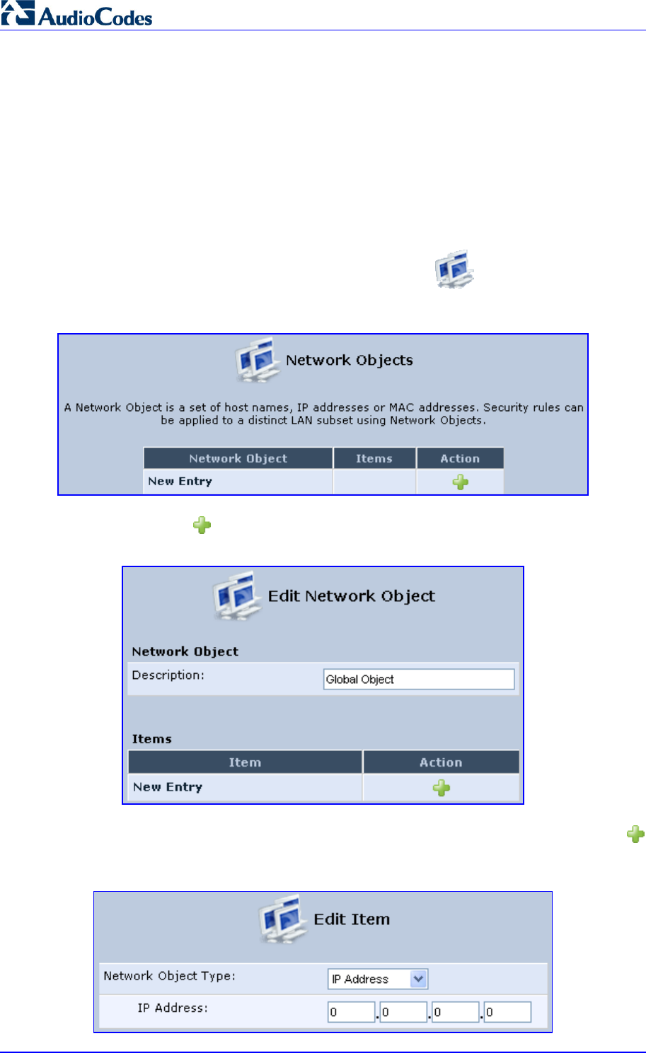
MP252 Multimedia Home Gateway 46 Document #: LTRT-23504
User's Manual
4.5.2 Defining Network Objects
Network objects is a method used to logically define a set of LAN hosts, according to one or
more MAC address, IP address, and host name. Defining such a group can assist when
configuring other system rules. For example, you can use network objects to apply security
rules based on host names instead of IP addresses. This may be useful, since IP addresses
change from time to time. Moreover, it is possible to define network objects according to
MAC addresses, making rule application more persistent against network configuration
settings.
¾ To define a network object:
1. In the 'Advanced' screen, click the Network Objects icon; the 'Network Objects'
screen appears.
Figure 4-10: Network Objects Screen
2. Click the New icon; the 'Edit Network Object' screen appears.
Figure 4-11: Edit Network Objects Screen
3. In the 'Description' field, enter a name for the network object, and then click the New
icon; the 'Edit Item' screen appears.
Figure 4-12: Edit Item Screen

MP252 Multimedia Home Gateway 4. Getting Started with the Web Interface
Version 3.4.0 47 June 2011
4. From the 'Network Object Type' drop-down lists, select a source address type:
• IP Address
• IP Subnet
• IP Range
• MAC Address
• Host Name
• DHCP Option (supporting options 60, 61, and 77)
• All Private IP Addresses
When selecting a method from the drop-down list, the screen refreshes, presenting the
respective fields by which to enter the relevant information.
5. Click OK to save the settings.
4.5.3 Defining Protocols
The Protocols feature incorporates a list of preset and user-defined applications and
common port settings. You can use protocols in various security features such as Access
Control and Port Forwarding. You may add new protocols to support new applications or edit
existing ones according to your needs.
¾ To define a protocol:
1. In the 'Advanced' screen, click the Protocols icon; the 'Protocols' screen appears.
Figure 4-13: Advanced - Protocols
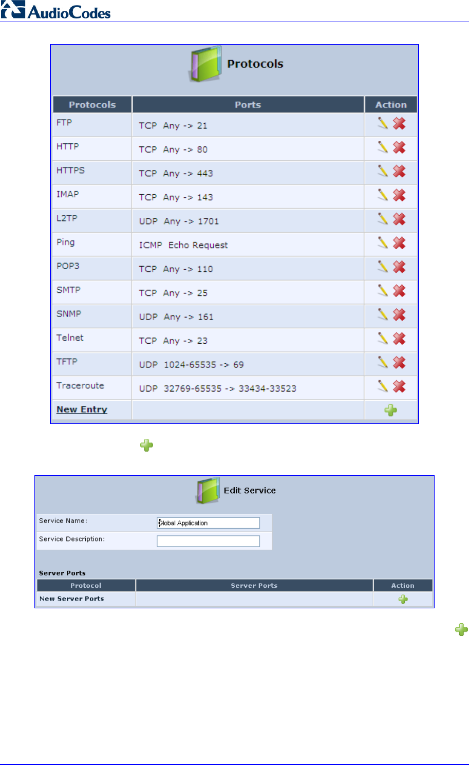
MP252 Multimedia Home Gateway 48 Document #: LTRT-23504
User's Manual
2. Click the New icon; the 'Edit Service' screen appears.
Figure 4-14: Advanced - Protocols - Edit Service
3. In the 'Service Name' field, enter the name of the service, and then click the New
icon; the 'Edit Service Server Ports' screen appears.
Figure 4-15: Advanced - Protocols - Edit Service - Server Ports
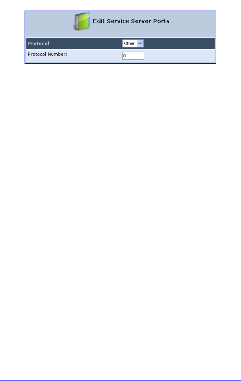
MP252 Multimedia Home Gateway 4. Getting Started with the Web Interface
Version 3.4.0 49 June 2011
4. You may choose any of the protocols available in the drop-down list, or add a new one
by selecting 'Other'. When selecting a protocol from the drop-down list, the screen
refreshes, presenting the respective fields by which to enter the relevant information.
5. Select a protocol and enter the relevant information.
6. Click OK to save the settings.
4.6 Logging out the Web Interface
To log out the MP252, click the Logout menu in the menu bar. When you logged out, the
‘Login’ screen is displayed, allowing you to re-login, if desired.

MP252 Multimedia Home Gateway 50 Document #: LTRT-23504
User's Manual
5 Viewing a Graphical Display of the MP252
Network
The Web interface allows you to view a graphical display of the network elements connected
to MP252. This is displayed in the ‘Map View’ screen, accessed by clicking the Home menu
in the menu bar.
You can click a displayed network element icon to access the relevant screen for configuring
the element.
The figure below displays an example of a network map for a deployed MP252:
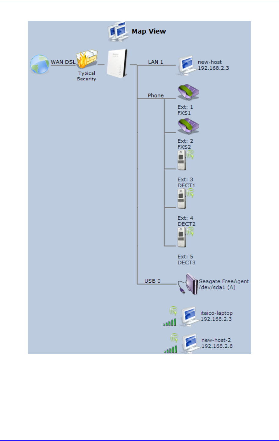
MP252 Multimedia Home Gateway 5. Viewing a Graphical Display of the MP252 Network
Version 3.4.0 51 June 2011
Figure 5-1: Map View Screen (Example)
MP252 Multimedia Home Gateway 52 Document #: LTRT-23504
User's Manual
The table below describes the possible icons that can be displayed in the ‘Map View’ screen:
Table 5-1: Map View Icon Description
Icon Description
Depicts the Internet connection (e.g., WAN Ethernet).
Click this icon to open the 'Quick Setup' screen (see Section 7.1 on page 57).
Depicts the firewall. The height of the wall (yellow "bricks") corresponds to
the security level (Minimum, Typical or Maximum).
Click this icon to open the ‘General Tab’ screen (see Section 14.1 on page
218).
Depicts MP252 and displays the currently software version.
Click this icon to open the 'Quick Setup' screen (see Section 7.1 on page 57).
Depicts an analog telephone connected to MP252.
Click this icon to open the ‘Extension Settings’ screen (see Section 8.7 on
page 95).
Depicts a DECT handset registered to the MP252.
Click this icon to open the ‘Extension Settings’ screen (see Section 8.7 on
page 95).
Depicts a computer (host) in the MP252 network. Each computer connected
to the network appears below the network symbol of the network through
which it is connected. This host is either a DHCP client that has received an
IP lease from MP252, or a host with a static IP address, auto-detected by
MP252.
Click this icon to open the ‘Host Information’ screen, displaying network
information of the host.
Note: MP252 recognizes a physically connected host and displays it in the
Network Map only after network activity from that host has been detected
(e.g. trying to browse to the Web management or to surf the Internet).
Depicts a computer connected to the Internet through the MP252 Wi-Fi
network.
Click this icon to open the ‘Host Information’ screen, displaying network
information of the host.
Depicts a host whose DHCP lease has expired and not renewed. The DHCP
lease is renewed automatically, unless the host is no longer physically
connected to MP252. This icon also depicts a static IP host that has no
network activity.
Depicts a file server (hard drive) that is connected to MP252 (typically
through the USB port). Click this icon to view the file server configuration.
Depicts a printer that is connected to MP252 and is shared by network users.
Click this icon to view the printer's settings.
Depicts a USB driver.

MP252 Multimedia Home Gateway 5. Viewing a Graphical Display of the MP252 Network
Version 3.4.0 53 June 2011
Icon Description
Depicts a USB disk-on-key that is connected to MP252.
Depicts a disconnected device.
MP252 Multimedia Home Gateway 54 Document #: LTRT-23504
User's Manual
6 Configuring Computers for Connecting to
the MP252 Network
This chapter describes how to configure computers to connect to the MP252 network, and
includes the following main areas:
Connecting wired computers – see Section 6.1 on page 54
Connecting wireless network computers – see Section 6.2 on page 56
6.1 Wired Computers
This section describes how to configure computers that connect to the MP252 network
through a LAN cable (i.e., wired).
You can configure the network interface of the computer using one of the following methods:
Statically define an IP address and DNS address
Automatically obtain an IP address using the MP252 embedded DHCP server
This section describes how to configure the computers network for the following operating
systems (OS):
Windows XP – see Section 0 on page 54
Linux – see Section 6.1.2 on page 55
Notes:
• It is recommended to set the computers to automatically obtain their IP
addresses (from a DHCP server).
• Refer to the Quick Installation Guide for instructions relating to installation
on a Windows™ operating system.
6.1.1 Configuring Computers Running on Windows XP
The procedure below describes how to configure a computer running on Windows XP OS to
automatically obtain its IP address (from a DHCP server, for example, MP252).
Note: For computers running Windows, the setup procedure is generally unnecessary
as Windows' default network settings are to obtain an IP address automatically.
However, it is recommended to follow the setup procedure to verify that all
communication parameters are valid and that the physical cable connections
are correct.
¾ To configure a computer running Windows XP for dynamic IP addressing:
1. Access 'Network Connections' from the Control Panel.
2. Right-click the Ethernet connection icon, and then choose Properties.
3. Under the General tab, select the 'Internet Protocol (TCP/IP)' component, and then
click the Properties button; the 'Internet Protocol (TCP/IP) Properties’ dialog box is
displayed.
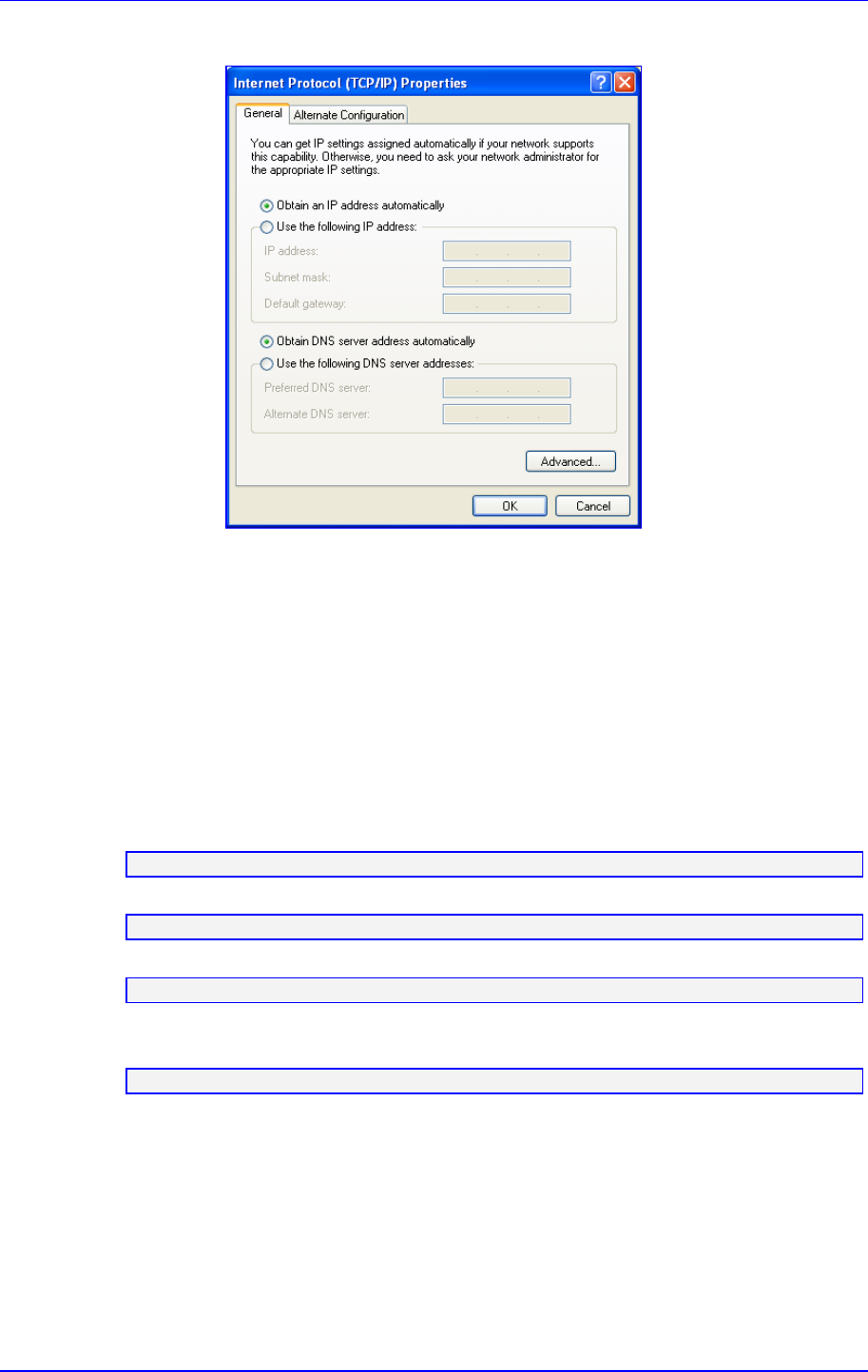
MP252 Multimedia Home Gateway 6. Configuring Computers for Connecting to the MP252 Network
Version 3.4.0 55 June 2011
Figure 6-1: Internet Protocol (TCP/IP) Properties Dialog Box
4. Select the Obtain an IP address automatically option.
5. Select the Obtain DNS server address automatically option.
6. Click OK to save the settings.
6.1.2 Configuring Computers Running on Linux
The procedure below describes how to configure a computer running on Linux OS to
automatically obtain its IP address (from a DHCP server, for example, MP252).
¾ To configure a computer running Linux for dynamic IP addressing:
1. Log in to the system as a super-user, by entering the following command:
su
2. View the network devices and allocated IP's, by typing the following command:
ifconfig
3. At the prompt, type the following command:
pump -i <dev>
Where <dev> is the network device name.
4. View the new allocated IP address, by typing the following command:
ifconfig
5. Make sure that no firewall is active on the device <dev>.
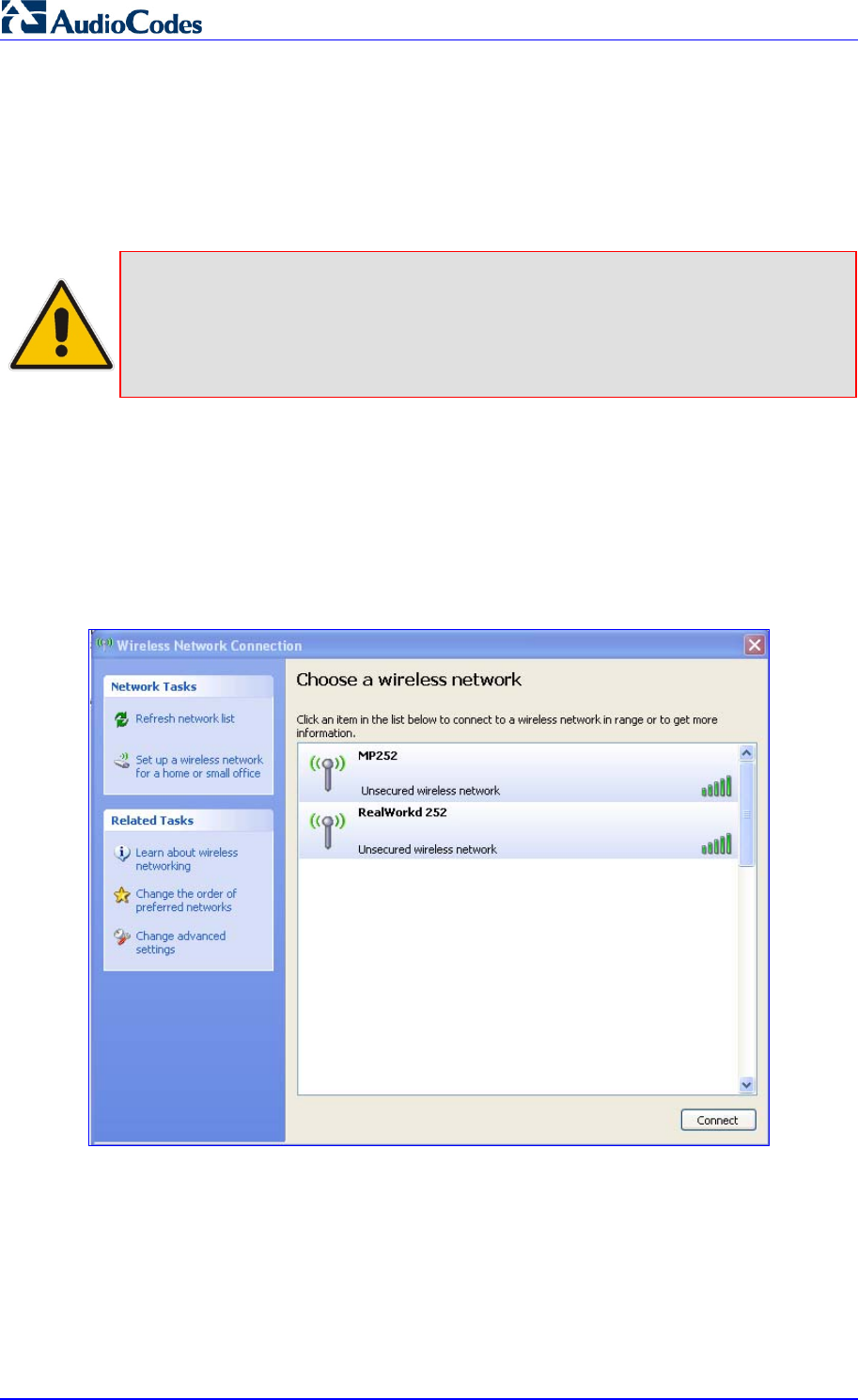
MP252 Multimedia Home Gateway 56 Document #: LTRT-23504
User's Manual
6.2 Connecting PC to MP252 Wireless Networks
This section describes how to configure the LAN computers to connect to the MP252
wireless network. If your computer has wireless capabilities, Windows automatically
recognizes the MP252 wireless network and creates a wireless connection.
Notes:
• To configure the MP252 LAN wireless connection, see Section 12.2.1 on
page 143.
• This section is based on computers running Microsoft Windows XP
Professional.
¾ To configure a computer to connect to MP252 wireless network:
1. From your Windows Start menu, point to Settings, Control Panel, Network
Connections, and then choose Wireless Connection; Windows starts enabling the
wireless connection.
2. On the Windows taskbar, right-click the Wireless Network Connection icon, and then
choose View Available Wireless Connections;
Figure 6-2: Available Wireless Networks
3. Double-click the MP252 wireless network name (i.e., "MP252"); your computer
establishes a wireless connection with MP252, indicated by the display of "Connected".
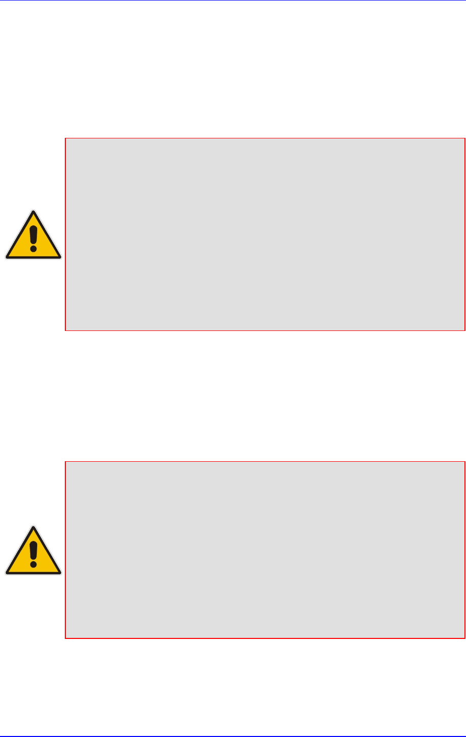
MP252 Multimedia Home Gateway 7. Connecting MP252 to the Internet
Version 3.4.0 57 June 2011
7 Connecting MP252 to the Internet
This section describes how to configure MP252 for connecting it to the Internet (WAN). You
can connect MP252 to the Internet using one of the following methods:
Configuring MP252 through the Web interface – see Section 7.1 on page 57
Using the MP252 Automatic Internet Dialer Detection feature – see Section 7.2 on page
66
Notes:
• MP252 automatically detects the physical WAN type (i.e., Ethernet or
ADSL). To change the WAN type, you must restore MP252 to factory
settings (see Section 18.8).
• When connected to ADSL, the LAN4/WAN Ethernet port can be used for
Ethernet LAN interface.
• When connected to an external modem through the Ethernet LAN4/WAN
port and MP252 obtains an IP address, the ADSL interface is disabled.
• If the Automatic Dialer feature is shipped preconfigured (i.e., enabled), then
MP252 automatically detects the Internet dialer type and therefore, Internet
connection configuration is unnecessary. However, it is recommended to
manually configure the Internet connection after the Automatic Dialer
process has completed (successfully or not). For more information on the
Automatic Dialer feature, see Section 7.2 on page 66.
7.1 Quickly Setting up an Internet Connection in the Web
Interface
You can quickly and easily set up a basic Internet connection using the Web interface’s
'Quick Setup' screen (as shown in Figure 7-1). This screen is displayed when you log in to
the Web interface (or you can click the Quick Setup menu from the menu bar).
Notes:
• Before configuring the MP252 Internet connection, ensure that you have
obtained relevant technical information on the Internet connection type from
your Internet Telephony Service Provider (ITSP). For example, whether you
are connected to the Internet using a static or dynamic IP address, or what
protocols such as PPTP or PPPoE are used to communicate over the
Internet.
• For advanced configuration of the WAN network, use the Network
Connections menu, as described in Section 12.1 on page 123.
• The ‘Email Address’ field in the ‘Quick Setup’ screen defines the
administrator's e-mail. System alerts and notifications are sent to this
address (typically, to the telephony carrier technicians). It is recommended
that only the administrator modify it.
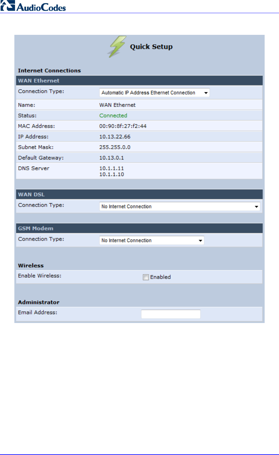
MP252 Multimedia Home Gateway 58 Document #: LTRT-23504
User's Manual
Figure 7-1: Quick Setup Screen
You can configure one of two main Internet connection types:
WAN Ethernet – see Section 7.1.1 on page 58
WAN DSL – see Section 7.1.2 on page 62
7.1.1 WAN Ethernet
MP252 supports the following WAN Ethernet connection types:
Manual IP address
Automatic IP address
Point-to-Point Protocol over Ethernet (PPPoE)
Point-to-Point Tunneling Protocol (PPTP)
Layer 2 Tunneling Protocol (L2TP)
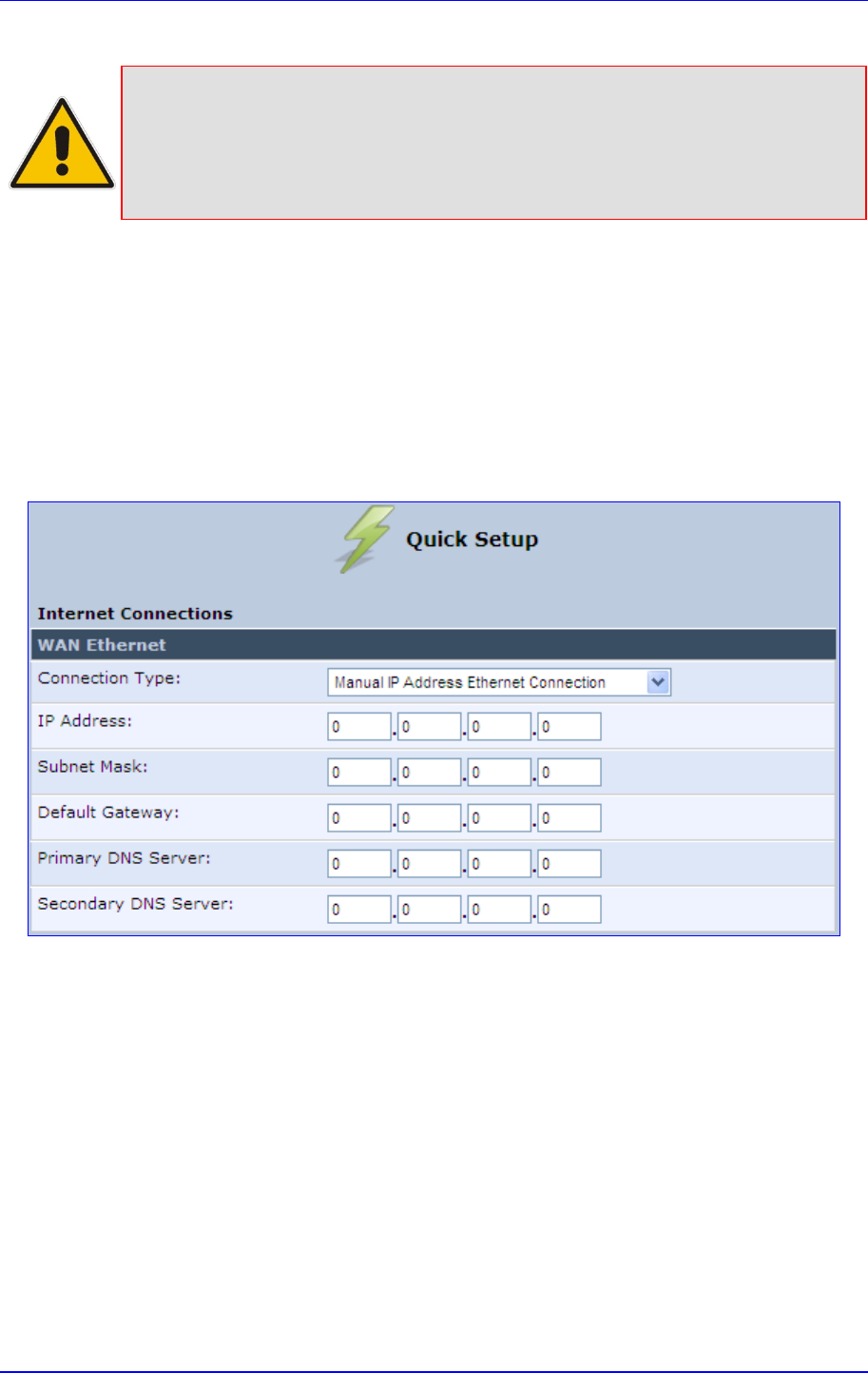
MP252 Multimedia Home Gateway 7. Connecting MP252 to the Internet
Version 3.4.0 59 June 2011
Notes:
• Automatic IP address is the default connection type.
• If you do not need an Internet (WAN Ethernet) connection, then in the
‘Quick Setup’ screen, from the ‘Connection Type’ drop-down list, select ‘
No Internet Connection’.
7.1.1.1 Manual IP Address Ethernet Connection
The procedure below describes how to connect to the Internet using a manually defined IP
address.
¾ To configure a manual IP address connection:
1. Under the WAN Ethernet group, from the 'Connection Type' drop-down list, select
'Manual IP Address Ethernet Connection'.
Figure 7-2: Manual IP Address WAN Ethernet Connection
2. According to your ISP's instructions, specify the following parameters:
• IP address
• Subnet mask
• Default Gateway
• Primary DNS server
• Secondary DNS server
7.1.1.2 Automatic IP Address Ethernet Connection
The procedure below describes how to connect to the Internet by automatically obtaining a
WAN IP address and DNS IP address from a DHCP server on the WAN. This method is the
default connection type.
¾ To configure automatic IP address connection:
Under the WAN Ethernet group, from the 'Connection Type' drop-down list, select
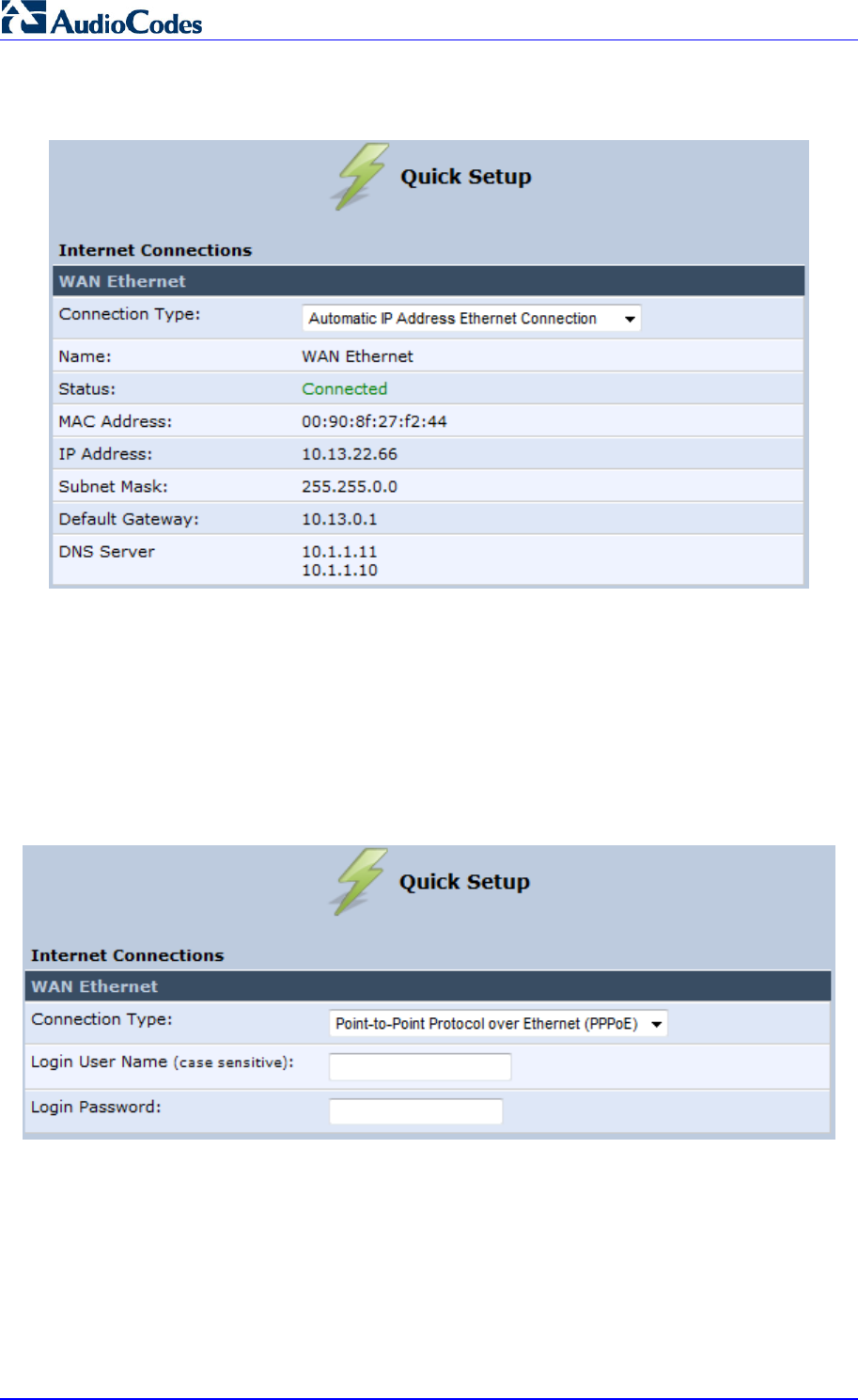
MP252 Multimedia Home Gateway 60 Document #: LTRT-23504
User's Manual
‘Automatic IP Address Ethernet Connection'.
Figure 7-3: Automatic IP Address WAN Ethernet Connection
7.1.1.3 PPPoE
The procedure below describes how to connect to the Internet by PPPoE
¾ To configure PPPoE connection:
1. Under the WAN Ethernet group, from the 'Connection Type' drop-down list, select
'Point-to-Point Protocol over Ethernet (PPPoE)'.
Figure 7-4: PPPoE WAN Ethernet Connection
2. Configure the PPPoE login username and password (provided by your ITSP).
7.1.1.4 PPTP
The procedure below describes how to connect to the Internet by PPTP.
¾ To configure PPTP connection:
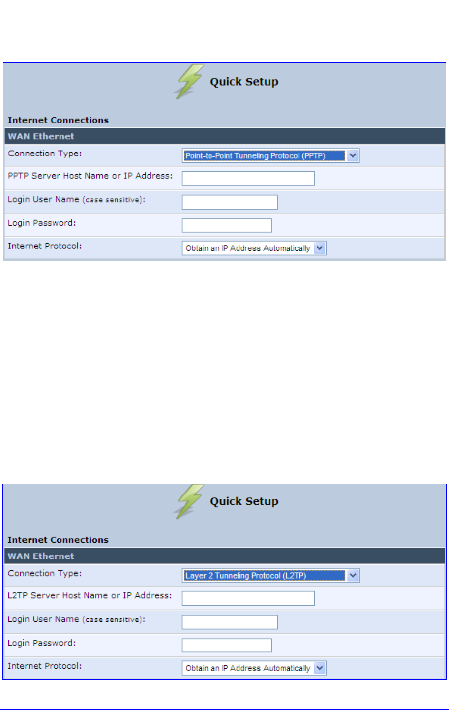
MP252 Multimedia Home Gateway 7. Connecting MP252 to the Internet
Version 3.4.0 61 June 2011
1. Under the WAN Ethernet group, from the 'Connection Type' drop-down list, select
'Point-to-Point Tunneling Protocol (PPTP)'.
Figure 7-5: PPTP WAN Ethernet Connection
2. Configure the following (provided by your ITSP):
• PPTP Server Host Name or IP Address
• Login user name
• Login password
3. From the ‘Internet Protocol’ drop-down lists, select the method for assigning an IP
address (provided by your ITSP).
7.1.1.5 L2TP
The procedure below describes how to connect to the Internet by L2TP.
¾ To configure L2TP connection:
1. Under the WAN Ethernet group, from the 'Connection Type' drop-down list, select
'Layer 2 Tunneling Protocol (L2TP)'.
Figure 7-6: L2TP WAN Ethernet Connection
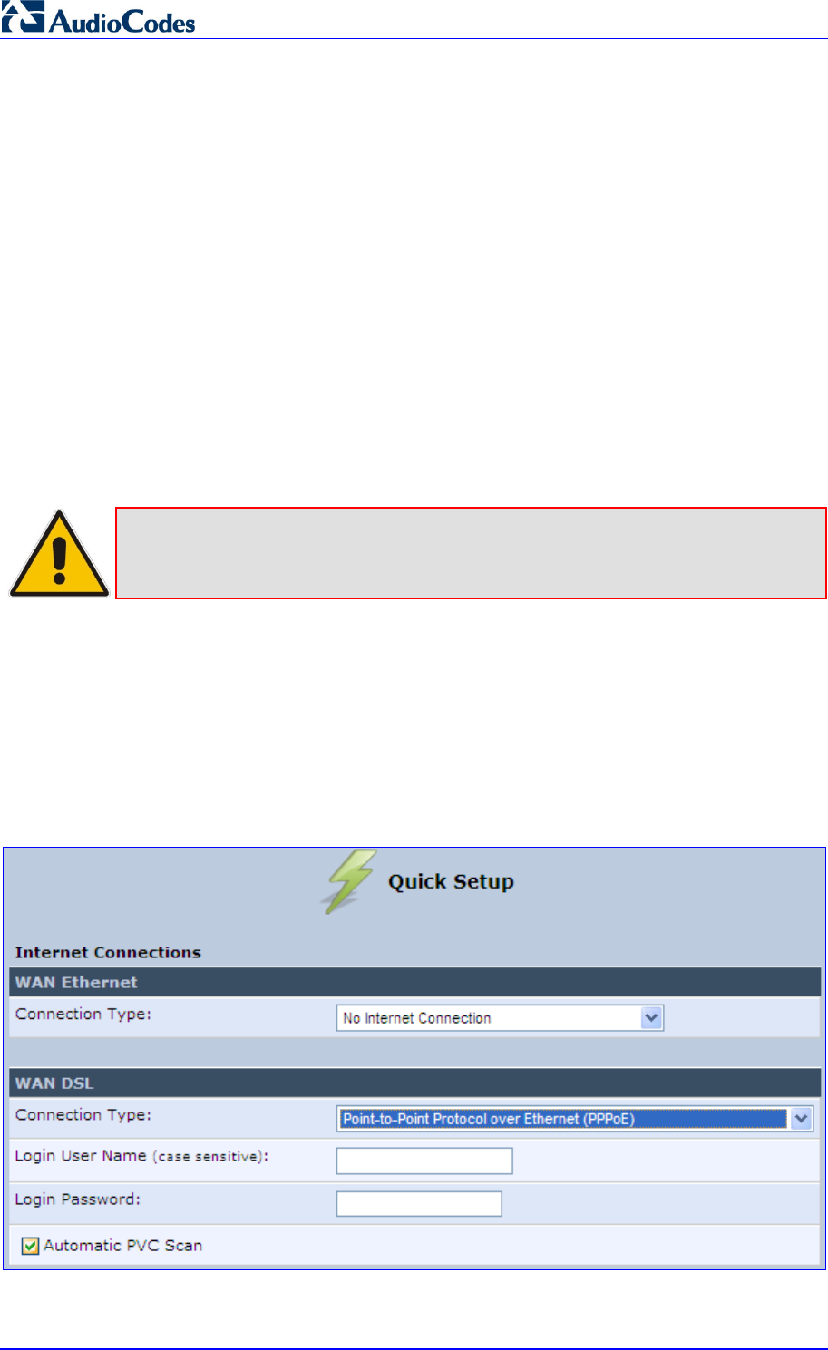
MP252 Multimedia Home Gateway 62 Document #: LTRT-23504
User's Manual
2. Configure the following (provided by your ITSP):
• L2TP Server Host Name or IP Address
• Login user name
• Login password
3. From the ‘Internet Protocol’ drop-down lists, select the method for assigning an IP
address (provided by your ITSP).
7.1.2 WAN DSL
MP252 supports the following WAN DSL connection types:
PPPoE
Point-to-Point Protocol over ATM (PPPoA)
Routed Ethernet Connection over ATM (Routed ETHoA)
LAN-WAN Bridged Ethernet Connection over ATM (Bridged ETHoA)
Classical IP over ATM (CLIP)
Note: If you do not need an Internet (WAN DSL) connection, then in the ‘Quick Setup’
screen, from the ‘Connection Type’ drop-down list, select ‘No Internet
Connection’.
7.1.2.1 PPPoE
The procedure below describes how to connect to the Internet by PPPoE.
¾ To configure PPPoE connection:
1. Under the WAN DSL group, from the 'Connection Type' drop-down list, select
'Point-to-Point Protocol over Ethernet (PPPoE)'.
Figure 7-7: PPPoE WAN DSL Internet Connection
2. Configure the following (provided by your ITSP):
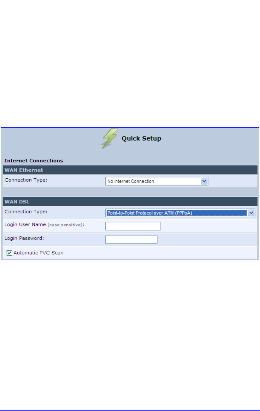
MP252 Multimedia Home Gateway 7. Connecting MP252 to the Internet
Version 3.4.0 63 June 2011
• Login user name
• Login password
3. By default, the 'Automatic PVC Scan' check box is selected, which means that MP252
configures the VPI, VCI, and encapsulation parameters automatically. To configure
these parameters manually, clear this check box (for more information, see Section
12.1.1.1 on page 125).
7.1.2.2 PPPoA
The procedure below describes how to connect to the Internet by PPPoA.
¾ To configure PPPoA connection:
1. Under the WAN DSL group, from the 'Connection Type' drop-down list, select
'Point-to-Point Protocol over ATM (PPPoA)'.
Figure 7-8: PPPoA WAN DSL Internet Connection
2. Configure the following (provided by your ITSP):
• Login user name
• Login password
3. By default, the 'Automatic PVC Scan' check box is selected, which means that MP252
configures the VPI, VCI, and encapsulation parameters automatically. To configure
these parameters manually, clear this check box (for more information, see Section
12.1.1.1 on page 125).
7.1.2.3 Routed ETHoA
The procedure below describes how to connect to the Internet by ETHoA.
¾ To configure routed ETHoA connection:
1. Under the WAN DSL group, from the 'Connection Type' drop-down list, select ‘Routed
Ethernet Connection over ATM (Routed ETHoA)'.
Figure 7-9: Routed ETHoA WAN DSL Internet Connection
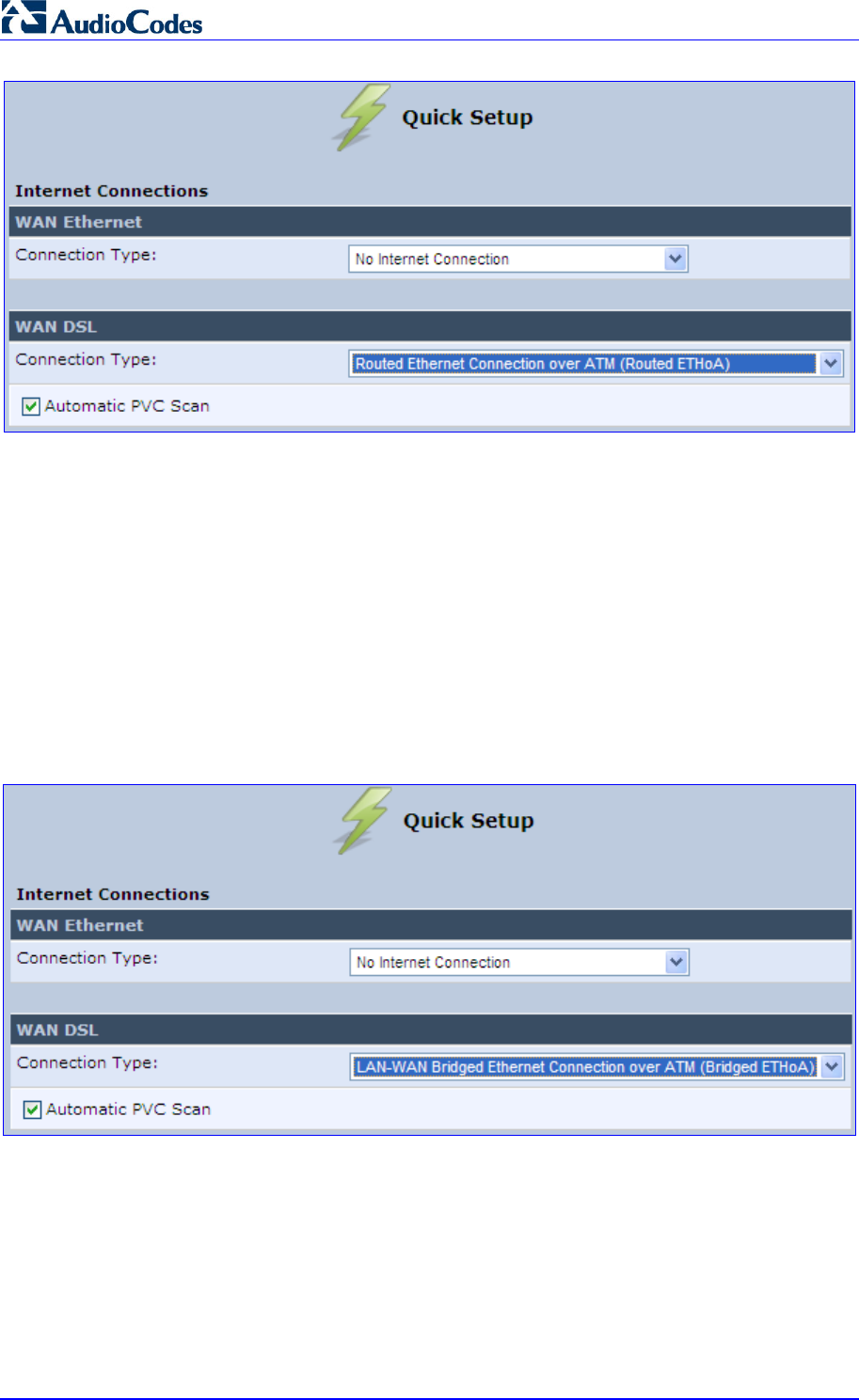
MP252 Multimedia Home Gateway 64 Document #: LTRT-23504
User's Manual
2. By default, the 'Automatic PVC Scan' check box is selected, which means that MP252
configures the VPI, VCI, and encapsulation parameters automatically. To configure
these parameters manually, clear this check box (for more information, see Section
12.1.1.1 on page 125).
7.1.2.4 Bridged ETHoA
The procedure below describes how to connect to the Internet by bridged ETHoA.
¾ To configure bridged ETHoA connection:
1. Under the WAN DSL group, from the 'Connection Type' drop-down list, select
‘LAN-WAN Bridged Ethernet Connection over ATM (Bridged ETHoA)'.
Figure 7-10: Bridged ETHoA WAN DSL Internet Connection
2. By default, the 'Automatic PVC Scan' check box is selected, which means that MP252
configures the VPI, VCI, and encapsulation parameters automatically. To configure
these parameters manually, clear this check box (for more information, see Section
12.1.1.1 on page 125).
7.1.2.5 CLIP
The procedure below describes how to connect to the Internet by CLIP.
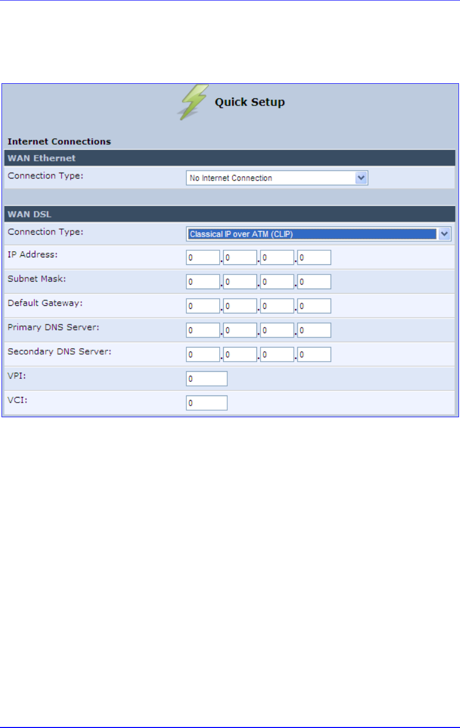
MP252 Multimedia Home Gateway 7. Connecting MP252 to the Internet
Version 3.4.0 65 June 2011
¾ To configure CLIP connection:
1. Under the WAN DSL group, from the 'Connection Type' drop-down list, select ‘Classical
IP over ATM (CLIP)'.
Figure 7-11: CLIP WAN DSL Internet Connection
2. Configure the following (provided by your ITSP):
• IP Address
• Subnet Mask
• Default Gateway IP address
• Primary DNS Server IP address
• Secondary DNS Server IP address
• VPI
• VCI
MP252 Multimedia Home Gateway 66 Document #: LTRT-23504
User's Manual
7.2 Using the Automatic Dialer for Internet Connection
The Automatic Dialer feature allows the service provider to use one type of pre-configured
MP252 for all the following Internet connection types:
WAN Ethernet (DHCP, LT2P or PPPoE)
WAN ADSL (PPPoE)
In the Private Labeling process, the factory setting is burned with the parameters of the
different dialers. When powered-up at the customer site, MP252 first detects the physical
WAN type (ADSL or Ethernet) and then attempts the relevant WAN connection methods.
The indication for a successful result is connection (i.e., receipt of an IP address) and a ping
test.
This section describes the recommended process for using the Automatic Dialer.
Notes:
• If the Automatic Dialer feature is shipped pre-configured (i.e., enabled),
then MP252 automatically detects the Internet dialer type and therefore,
configuration of the Internet connection is not necessary. However, it is
recommended to manually configure the Internet connection after the
Automatic Dialer process has completed (successfully or not).
• If you manually configure the Internet connection in the Web interface, the
Automatic Dialer feature becomes disabled.
7.2.1 Recommended Configuration
The recommended factory settings for the Automatic Dialer feature are shown below:
(auto_dialer_detect
(enabled(1))
(done(0))
(connection_type
(0
(type(DHCP))
(enabled(1))
(max_dialer_conn_time(20))
)
(1
(type(L2TP))
(enabled(1))
(server_ip(<Server Name or IP>))
(username(<User Name>))
(password(<Password>))
(max_dialer_conn_time(120))
)
(2
(type(PPPOE))
MP252 Multimedia Home Gateway 7. Connecting MP252 to the Internet
Version 3.4.0 67 June 2011
(enabled(1))
(username(<User Name>))
(password(<Password>))
(max_dialer_conn_time(120))
)
)
(auto_detect_retries(15))
(ping_retries(4))
(ping_retries_timeout(2))
(ADSL
(vpi(8))
(vci(48))
(encap(LLC))
)
)
(system
(network
(internet_url(<Address or Domain Name for Ping Test>))
)
)
Note: If the ADSL section in the factory settings is omitted, the MP252 performs an
automatic PVC scan. When configuring manual PVC values (VPI and VCI), the
connection is faster.
.
MP252 Multimedia Home Gateway 68 Document #: LTRT-23504
User's Manual
7.2.2 Setting up and Starting the Automatic Dialer
The procedure below describes how to setup and start the Automatic Dialer feature.
¾ To setup and start Automatic Dialer:
1. Power off the MP252.
2. Connect the ADSL or Ethernet cables.
Note: If you are using an ADSL connection, DO NOT connect any cable to the
WAN/LAN4 port. Connecting this port causes the Automatic Dialer to fail.
3. Power on the MP252; the Automatic Dialer begins its operation and you can view the
progress status by checking the MP252 LEDs (see Section 3.1.1.2.2 on page 26).
Notes:
• If the connection is ADSL, the Automatic Dialer usually connects in the first
iteration (after less than 10 seconds, when configuring manual PVC). In
some cases, the Automatic Dialer may connect in the second iteration (up
to 4 minutes).
• If the connection is WAN Ethernet:
- For DHCP, the connection is fast.
- For L2TP, the connection takes up to ~2 minutes.
- For PPPoE, the connection can take up to ~4 minutes.
MP252 Multimedia Home Gateway 7. Connecting MP252 to the Internet
Version 3.4.0 69 June 2011
7.2.3 Quitting Automatic Dialer for Manual Configuration
If, for any reason, you need to manually configure the Internet connection, you first need to
stop the Automatic Dialer feature and then manually configure the connection, as described
below,
¾ To quit Automatic Dialer and manually configure the Internet connection:
1. Power off the MP252.
2. Disconnect the WAN ADSL or Ethernet cable.
3. Power on the MP252.
4. Wait for the Automatic Dialer process to end (i.e., the Broadband LED stops blinking).
5. Log in to the MP252 Web interface.
6. Manually configure the Internet connection using the 'Quick Setup' screen (see Section
7.1 on page 57). This ensures that the Automatic Dialer feature does not re-activate
itself after the MP252 resets.
Once the MP252 successfully connects to the Internet, it downloads its configuration file from
the server.
Note: The configuration file must include the following parameter to indicate that
Automatic Dialer is no longer needed: auto_dialer_detect/done = 1.
MP252 Multimedia Home Gateway 70 Document #: LTRT-23504
User's Manual
8 Configuring VoIP Parameters
The VoIP parameters are mainly configured in the 'Voice over IP' screen. This screen is
accessed by clicking the Voice over IP menu in the side menu bar. The ‘Voice over IP'
screen provides tabs for configuring the following:
Signaling protocol (i.e., Session Initiation Protocol / SIP) – see Section 8.1 on page 70
Dialing – see Section 8.2 on page 78
Media streaming – see Section 8.3 on page 83
Voice and fax – see Section 8.4 on page 84
Supplementary services – see Section 8.5 on page 88
Line settings – see Section 8.6 on page 91
Line extensions – see Section 8.7 on page 94
Speed dials – see Section 8.9 on page 97
Telephone interfaces – see Section 8.9 on page 97
In addition to the above, you can select the region in which your MP252 is located so that
your analog telephone complies with the line standards (e.g., line impedance) of the area.
For more information, see Section 8.10 on page 98.
Notes:
• By default, the ‘Voice over IP’ screens initially display only basic
parameters. To view all the parameters, click the Advanced button in the
required screen.
• Once you have configured the VoIP parameters, you can start using your
analog telephones, as described in Chapter 10 on page 101. For using
your DECT handset(s), see Part II.

MP252 Multimedia Home Gateway 8. Configuring VoIP Parameters
Version 3.4.0 71 June 2011
8.1 Configuring the SIP Signaling Protocol
The procedure below describes how to configure the SIP parameters.
¾ To configure SIP parameters:
1. From the menu bar, click the Voice Over IP menu; the following screen appears:
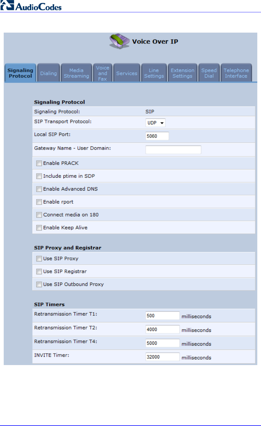
MP252 Multimedia Home Gateway 72 Document #: LTRT-23504
User's Manual
Figure 8-1: Signaling Protocol Tab Screen
2. Configure the parameters, as required. For a description of the parameters displayed on
this screen, see Table 8-1.
3. Click OK to save your settings.
Table 8-1: Signaling Protocol Tab Parameters Description

MP252 Multimedia Home Gateway 8. Configuring VoIP Parameters
Version 3.4.0 73 June 2011
Parameter Description
Signaling Protocol Group
Signaling Protocol (Read-only field.) Displays the signaling protocol running on the device.
Note: Currently, only SIP is supported.
SIP Transport Protocol Defines the SIP transport type - UDP (default), TCP, or TLS.
Note: This parameter appears only in 'Advanced' mode.
Local SIP Port Defines the UDP / TCP port on which the SIP stack listens. The defaul
t
port is 5060.
Note: This parameter appears only in 'Advanced' mode.
Local SIP TLS Port Defines the TLS port on which the SIP stack listens. The default port is
5060.
Note: This parameter appears only if you select ‘TLS’ as the SIP
transport protocol.
Gateway Name - User
Domain Defines the MP252 domain name which is sent in the SIP From heade
r
of outgoing INVITE messages.
Note: This parameter appears only in 'Advanced' mode.
Enable PRACK When enabled, MP252 replies with a PRACK message upon receipt o
f
a reliable provisional response. MP252 does not initiate reliable
provisional responses.
Note: This parameter appears only in 'Advanced' mode.
Include ptime in SDP When enabled, MP252 adds the ptime field to the SDP message body.
Note: This parameter appears only in 'Advanced' mode.
Enable Advanced DNS
Advanced DNS Type
Note: This parameter is available only if the ‘Enable Advanced DNS’
check box is selected.
Enable rport When enabled, MP252 adds the rport parameter to the relevant SIP
message fields.
Note: This parameter appears only in 'Advanced' mode.
Connect media on 180 When enabled, media is connected upon receipt of SIP 180, 183, or
200 messages. When this parameter is disabled, media is connected
upon receipt of 183 and 200 messages only.
Note: This parameter appears only in 'Advanced' mode.
Enable Keep Alive When enabled, a keep-alive notification is sent every user-defined
interval to the SIP registrar server.
Note: This parameter appears only in 'Advanced' mode.
Keep-Alive Type The type of keep-alive mechanism sent to the SIP registrar:
• Using SIP OPTIONS: sends SIP OPTIONS messages
• Using an Empty UDP packet: sends empty UDP packets
Note: This parameter is available only if the ‘Enable Keep Alive’ chec
k
box is selected.
Keep-Alive Period Defines the periodic interval for keep-alive messages.
Note: This parameter is available only if the ‘Enable Keep Alive’ chec
k
box is selected.

MP252 Multimedia Home Gateway 74 Document #: LTRT-23504
User's Manual
Parameter Description
SIP Proxy and Registrar
Use SIP Proxy When checked, outgoing calls are routed to the configured SIP proxy. I
f
the 'Use SIP Proxy IP and Port for Registration' check box is also
selected, the configured SIP proxy is also used as the registrar,
allowing incoming calls.
Host Name or Address Defines the IP address or host name of the SIP proxy.
Note: This parameter is available only if the ‘Use SIP Proxy’ check bo
x
is selected.
Proxy Port Defines the port (UDP, TCP, or TLS) of the SIP proxy.
Note: This parameter is available only if the ‘Use SIP Proxy’ check bo
x
is selected.
Maximum Number of
Authentication Retries Defines how many times authenticated register messages are re-sent i
f
SIP 401 or 407 responses with a different “nonce” are received.
Note: This parameter is available only if the ‘Use SIP Proxy’ check bo
x
is selected.
Use SIP Proxy IP and Port
for Registration When selected (default), the SIP proxy’s IP address and port is also
used for registration. When selected, there is no need to configure the
address / port of the registrar (only the ‘Register Expires’ and ‘Registe
r
Expires Failed’ parameters – described later).
Note: This parameter is available only if the ‘Use SIP Proxy’ check bo
x
is selected.
Sip Security MP252's firewall can be configured to block incoming packets that have
the SIP signaling port as their destination. You can configure up to two
SIP entities (for example, the SIP Proxy or an SBC), which are not
blocked by the firewall.
The default value is ‘Allow all SIP traffic’.
Note: This parameter is available only if the ‘Use SIP Proxy’ check bo
x
is selected.
Address Type Selects the address type of the additional SIP entity - IP address or
host name.
Note: This parameter is available only if the 'Sip Security' field is set to
‘Allow SIP traffic from Proxy and Additional SIP Entity’.
SIP Entity Address Defines the address or host name (depending on the settings of the
‘Address Type’ field) of the additional SIP entity.
Note: This parameter is available only if the 'Sip Security' field is set to
‘Allow SIP traffic from Proxy and Additional SIP Entity’.
Use Redundant Proxy Enables the use of a redundant proxy.
Note: This parameter is available only if the 'Use SIP Proxy IP and Por
t
for Registration' check box is selected.
Redundant Proxy Address Defines the IP address of the redundant proxy.
Note: This parameter is available only if the 'Use Redundant Proxy’
check box is selected.
Redundant Proxy Port Defines the port of the redundant proxy.
Note: This parameter is available only if the 'Use Redundant Proxy’
check box is selected.

MP252 Multimedia Home Gateway 8. Configuring VoIP Parameters
Version 3.4.0 75 June 2011
Parameter Description
Redundant Proxy Keep Alive
Period Defines the interval between keep-alive packets (SIP OPTIONS) which
are used by the proxy redundancy mechanism to check the connection
status.
Note: This parameter is available only if the 'Use Redundant Proxy’
check box is selected.
Switch back to Primary SIP
proxy when available When selected, MP252 switches back to the primary proxy server
when communication with it returns.
Use SIP Registrar When selected, enables the use of a separate SIP registrar server.
Registrar Address Defines the IP address or host name of the registrar server.
Note: This parameter is available only if the 'Use SIP Registrar’ check
box is selected.
Registrar Port Defines the port (UDP or TCP) of the registrar server.
Note: This parameter is available only if the 'Use SIP Registrar’ check
box is selected.
Register Expires Defines the registration timeout, in seconds.
Note: This parameter is available only if the 'Use SIP Registrar’ or ‘Use
SIP Proxy IP and Port for Registration’ check box is selected.
Register Failed Expires Defines the timeout between registration attempts in case of a
registration failure (e.g. due to a network problem).
Note: This parameter is available only if the 'Use SIP Registrar’ or ‘Use
SIP Proxy IP and Port for Registration’ check box is selected.
Use SIP Outbound Proxy When selected (default), an outbound SIP proxy is used (all SIP
messages are sent to this server as the first hop).
Note: This parameter appears only in 'Advanced' mode.
Outbound Proxy IP Defines the IP address of the outbound Proxy. If this parameter is set,
all outgoing messages (including registration messages) are sent to
this Proxy according to the Stack behavior.
Note: This parameter is available only if 'Use SIP Outbound Proxy' is
selected.
Outbound Proxy Port The Port on which the outbound Proxy listens.
Note: This parameter is available only if 'Use SIP Outbound Proxy' is
selected.
SIP Timers
Note: This group appears only in 'Advanced' mode.
Retransmission Timer T1 The SIP T1 retransmission timer according to RFC 3261
Retransmission Timer T2 The SIP T2 retransmission timer according to RFC 3261
Retransmission Timer T4 The SIP T4 retransmission timer according to RFC 3261
INVITE Timer The SIP INVITE timer according to RFC 3261
NAT Traversal
Enable STUN When selected, the SIP STUN Manager is enabled. The SIP STUN
Manager resolves private addresses to public addresses.
Note: This parameter appears only in 'Advanced' mode.

MP252 Multimedia Home Gateway 76 Document #: LTRT-23504
User's Manual
Parameter Description
STUN Server Address Defines the IP address of the STUN server used to resolve private
addresses.
Note: This parameter is available only if 'Enable STUN' is selected.
STUN Server Port Defines the port of the STUN server.
Note: This parameter is available only if 'Enable STUN' is selected.
Subnet Mask Defines the subnet mask address of the STUN server used to resolve
private addresses.
Note: This parameter is available only if 'Enable STUN' is selected.

MP252 Multimedia Home Gateway 8. Configuring VoIP Parameters
Version 3.4.0 77 June 2011
8.1.1 Configuring Proxy Redundancy
The Redundant Proxy feature allows the configuration of a backup SIP proxy server to
increase Quality of Service (QoS). Once this feature is enabled, MP252 identifies cases
where the primary proxy does not respond to SIP signaling messages. In these cases,
MP252 registers to the redundant proxy and seamlessly continues normal functionality,
without any noticeable connectivity failure or malfunction with the primary proxy.
The Redundant Proxy feature includes two operational modes:
Asymmetric mode: This mode assigns the primary proxy a higher priority for
registration over the redundant proxy. Once MP252 is registered to the primary proxy, it
sends keep-alive messages (using SIP OPTIONS messages) to the primary proxy. If
the primary proxy does not respond, MP252 registers to the redundant proxy, but
continues sending keep-alive messages to the primary proxy. If the primary proxy
responds to these keep-alive messages, MP252 re-registers to the primary proxy.
Symmetric mode: In this mode, both proxies are assigned the same priority for
registration. Once MP252 is registered to a proxy (primary or redundant), it sends
keep-alive messages to this proxy. MP252 switches proxies only once the proxy to
which it has registered does not respond.
In both modes, the following applies:
If MP252 is not registered (i.e., if the proxy server - redundant or primary - to which
MP252 currently tries to register does not respond), MP252 attempts to register to an
alternative proxy. These attempts continue until MP252 successfully registers.
If this feature is enabled and you reboot MP252, it registers to the last proxy to which it
was trying to register (not necessarily to the primary proxy).
¾ To configure proxy redundancy:
1. From the menu bar, click the Voice Over IP menu; the Signaling Protocol tab screen
appears.
2. Define a primary proxy server (under the SIP Proxy and Registrar group):
a. Select the ‘Use SIP Proxy’ check box.
b. In the 'Host Name or Address' field, enter the primary proxy's IP address.
c. In the 'Proxy Port' field, enter the primary proxy's port number.
3. Define a redundancy proxy server (under the SIP Proxy and Registrar group):
a. Select one of the following check boxes: 'Use SIP Registrar' or 'Use SIP Proxy IP
and Port for Registration'.
a. Select the 'Use Redundant Proxy' check box.
b. In the 'Redundant Proxy Address' field, enter the redundant proxy's IP address or
DNS name.
c. In the 'Redundant Proxy Port' field, enter the redundant proxy's port number.
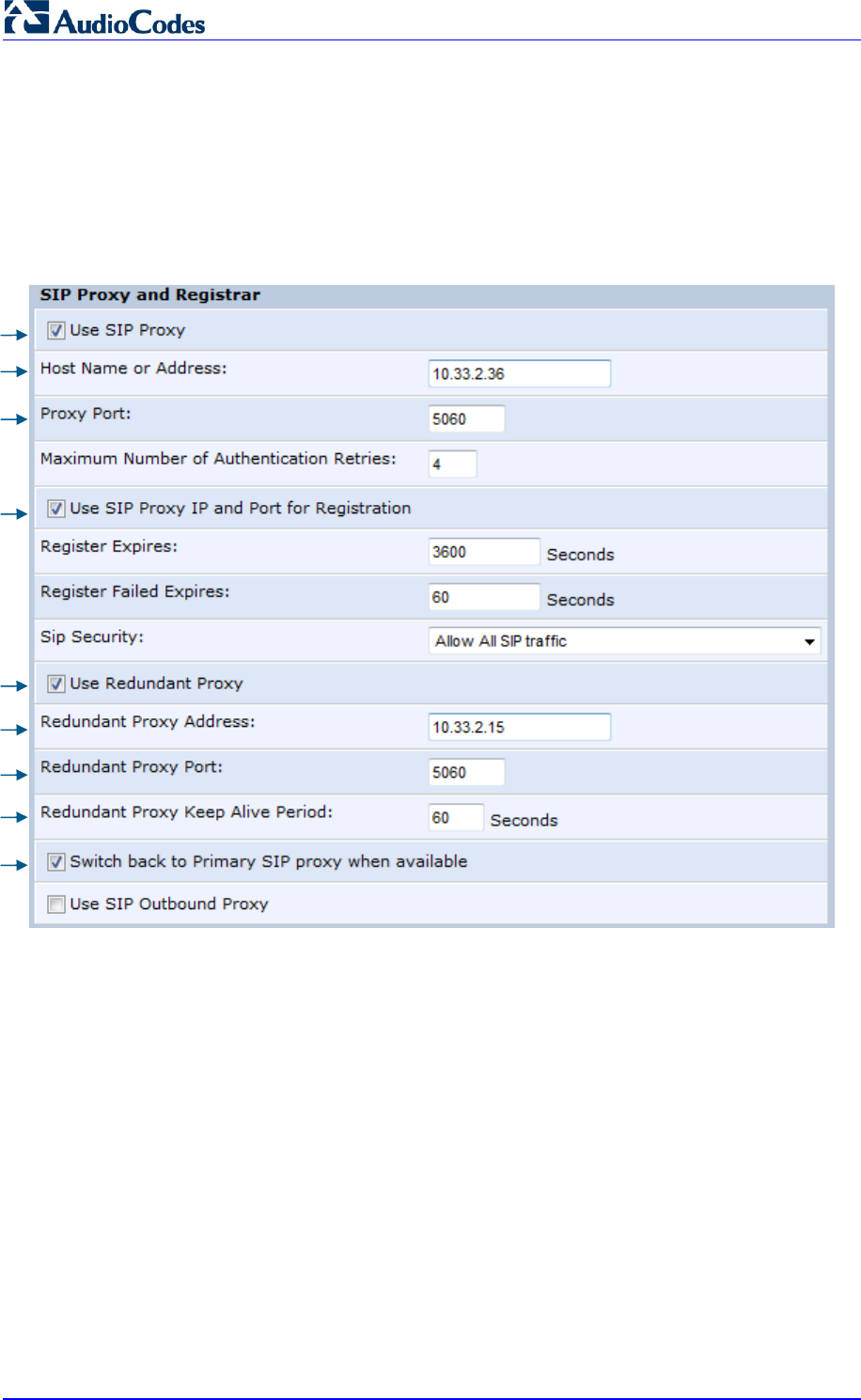
MP252 Multimedia Home Gateway 78 Document #: LTRT-23504
User's Manual
d. In the 'Redundant Proxy Keep Alive Period' field, enter the rate (in seconds) of the
keep-alive messages for sending to the proxy. The valid range is 10 to 86,400
seconds (i.e., 24 hours). The default value is 60 sec.
e. To toggle between Symmetric and Asymmetric modes, use the 'Switch back to
Primary SIP proxy when available' check box.
♦ Asymmetric mode - select the check box (i.e., mark it)
♦ Symmetric mode - clear the check box
Figure 8-2: Configuring Proxy Redundancy
4. Click OK to save your settings.
2-a
3-a
2-b
2-c
3-a
3-b
3-c
3-d
3-e
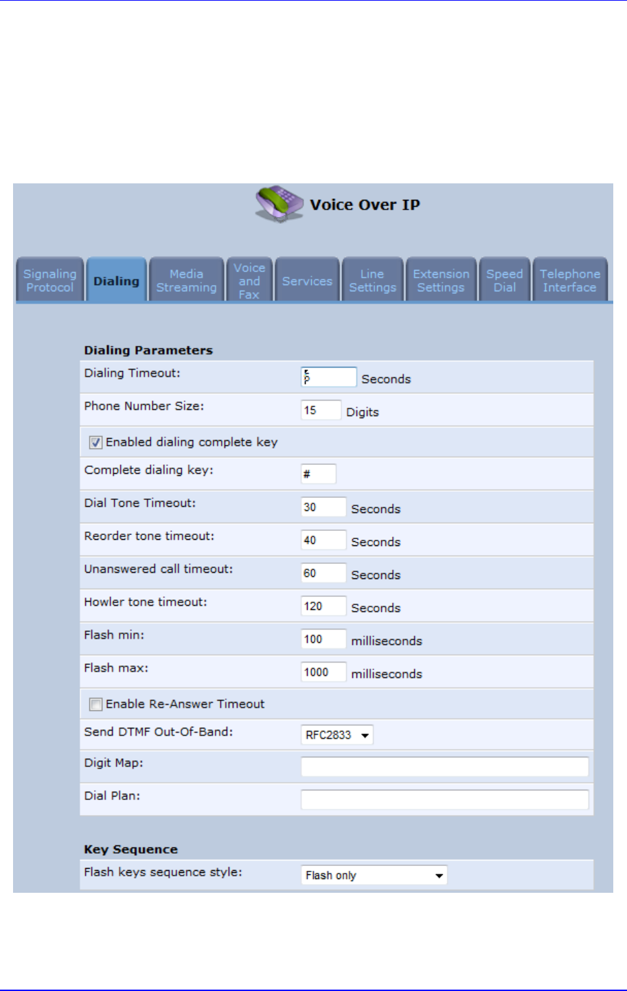
MP252 Multimedia Home Gateway 8. Configuring VoIP Parameters
Version 3.4.0 79 June 2011
8.2 Configuring Dialing Parameters
The procedure below describes how to configure the dialing parameters.
¾ To configure dialing parameters:
1. In the 'Voice Over IP' screen, click the Dialing tab; the following screen appears.
Figure 8-3: Dialing Tab Screen
2. Configure the parameters, as required. For a description of the parameters displayed on
this screen, see Table 8-2.
3. Click OK to save your settings.

MP252 Multimedia Home Gateway 80 Document #: LTRT-23504
User's Manual
Table 8-2: Dialing Tab Parameters Description
Parameter Description
Dialing Parameters
Dialing Timeout Defines the duration (in seconds) of allowed inactivity between dialed digits.
When you work with a proxy, the number you have dialed before the dialing
process has timed out is sent to the proxy as the user ID to be called. This is
useful for calling remote parties without creating a speed dial entry
(assuming the remote party is registered with the proxy).
Phone Number Size Defines the maximum length of shortcut numbers that you can enter and the
maximum number of digits that you can dial.
Enabled dialing
complete key When selected (default), you can define a key that when pressed forces
MP252 to make a call to the dialed digits even if there is no match in the dial
plan or digit map. The key is defined in the ‘Complete dialing key’ field, which
appears when this parameter is selected.
Note: This parameter appears only in 'Advanced' mode.
Complete dialing key Defines the key that when pressed forces MP252 to make a call to the dialed
digits even if there is no match in the dial plan or digit map. The default value
is the pound (#) key.
Note: This parameter is available only if the ‘Enabled dialing complete key’ is
selected.
Dial Tone Timeout Defines the duration of the dial tone (in seconds). If the limit is exceeded, the
dial tone stops and you a reorder tone is played.
Reorder Tone Timeout Defines the duration (in seconds) of the reorder tone. The reorder tone is
played, for example, when MP252 receives a SIP 486 response. If the limit is
exceeded, the reorder tone stops and a howler tone is played.
Note: This parameter appears only in 'Advanced' mode.
Unanswered call
timeout Defines the timeout before MP252 automatically sends a SIP CANCEL
message. When MP252 makes a call and the other side doesn’t answer,
MP252 sends a CANCEL message after this timeout.
Note: This parameter appears only in 'Advanced' mode.
Howler Tone Timeout Defines the duration (in seconds) of the howler tone. If the limit is exceeded,
the howler tone stops playing. The howler tone informs a user that the user's
phone has been left in an off-hook state.
Note: This parameter appears only in 'Advanced' mode.
Flash min Defines the duration (in ms) after which you can begin to perform a flash
hook.
Flash max Defines the maximum duration (in ms) that the flash hook button can be
pressed, after which the call is disconnected.
Enable Re-Answer
Timeout When selected, the ‘Re-Answer Timeout’ field appears, allowing you to
define the timeout after on-hooking an active call and then off-hooking it
again. Once this time expires and the phone has not been off-hooked again,
the call is disconnected.
Send DTMF Out-Of-
Band
Defines how the DTMF tones are sent (‘Inband’, ‘RFC2833’, or ‘Via SIP’).
DTMFs are the tones generated by your telephone's keypad.
Note: This parameter appears only in 'Advanced' mode.

MP252 Multimedia Home Gateway 8. Configuring VoIP Parameters
Version 3.4.0 81 June 2011
Parameter Description
Digit Map Defines formats (or patterns) for the dialed number. A match to one of the
defined patterns terminates the dialed number. For an explanation on digit
map syntax, see Section 8.2.1 on page 81.
Note: This parameter appears only in 'Advanced' mode.
Dial Plan Defines patterns to translate to specific SIP destination addresses. For dial
plan syntax rules for patterns entered to the left of the '=' sign, see Section
8.2.1 on page 81.
Note: This parameter appears only in 'Advanced' mode.
Key Sequence
Flash keys sequence
style
Defines the key sequence with the flash button:
‘Flash only’ (default) = uses only the phone's Flash button. There are
three scenarios:
9 During an existing call, if the user presses Flash, the call is put on
hold, a dial tone is heard and the user is able to initiate a second call.
Once the second call is established, on-hooking transfers the first
(held) call to the second call.
9 During an existing call, if the user presses Flash, the call is put on
hold and a dial tone is heard. The user can initiate a second call and
establish a 3-way conference by again pressing Flash after the
second call is initiated.
9 During an existing call, if a call comes in (call waiting), pressing Flash
puts the active call on hold and answers the waiting call; pressing
Flash again toggles between these two calls.
‘Flash + digits sequence’ = Flash button with a key sequence:
9 Flash + 1 holds a call or toggles between two existing calls.
9 Flash + 2 makes a call transfer.
9 Flash + 3 establishes a 3-way conference.
'Send Flash Hook Via SIP' = you can modify the SIP INFO message that
is sent upon Flash. You can change the Content Type header field and
Message Body field.
Note: This parameter appears only in 'Advanced' mode.
SIP INFO Header When the key sequence is set to 'Send Flash Hook Via SIP', you can modif
y
the Content Type header field of the SIP INFO message.
For example: "application/broadsoft; version = 1.0"
Note: This parameter appears only when the ‘Flash keys sequence style’
field is set to 'Send Flash Hook Via SIP'.
SIP INFO Body When the key sequence is set to 'Send Flash Hook Via SIP', you can modif
y
the Message Body field of the SIP INFO message.
For example: " event flashhook"
Note: This parameter appears only when the ‘Flash keys sequence style’
field is set to 'Send Flash Hook Via SIP'.
8.2.1 Syntax for Digit Maps and Dial Plans
Digit maps and dial plans are defined using special syntax rules, configured in the 'Dialing'
screen (see Section 8.2 on page 78).
Digit Maps: A phone's digit map allows MP252 to know when an entered telephone
number is complete and therefore, when it should initiate the call. If the phone digit map
is defined incorrectly, MP252 might start to dial before the telephone user has entered
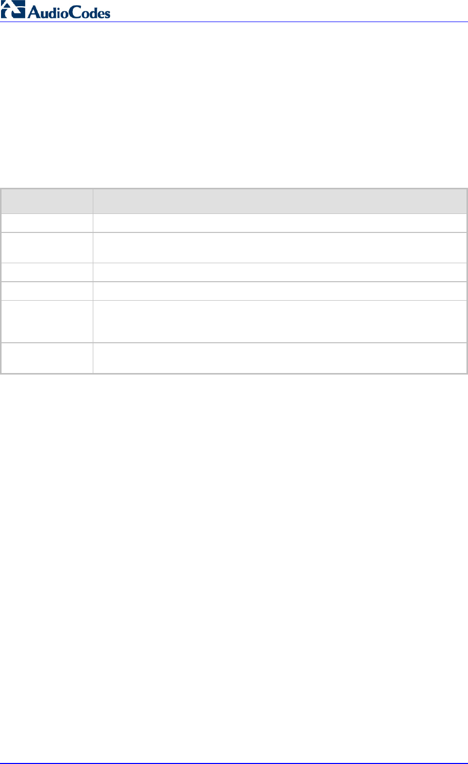
MP252 Multimedia Home Gateway 82 Document #: LTRT-23504
User's Manual
all the required digits. A digit map is defined either by a (case insensitive) "string" or by a
list of strings. Each string in the list is an alternative numbering scheme, specified either
as a set of digits or as an expression over which MP252 attempts to find a shortest
possible match. The syntax that can be used in each numbering scheme is described in
the table below.
Dial Plans: A dial plan translates specific patterns into specific SIP destination
addresses. For example, dial plan rule "4xxx=Line_\\\@10.1.2.3" sends a dialed
number consisting of the digit “4” followed by any three digits to IP address 10.1.2.3.
The syntax of the pattern on the left of the '=' sign is described in the table below.
Table 8-3: Dial Plan (for Left of '=' Sign) and Digit Map Syntax
Type Syntax
Digit A digit from "0" to "9".
DTMF A digit, or one of the symbols "A", "B", "C", "D", "#", or "*". Extensions may be
defined.
Wildcard The symbol "x" which denotes any digit ("0" to "9").
Range One or more DTMF symbols enclosed between square brackets ("[" and "]").
Sub-range Two digits separated by a hyphen ("-") which matches any digit between and
including the two. The subrange can only be used inside a range construct, i.e.,
between "[" and "]".
Position
A
period (".") which matches an arbitrary number, including zero, of occurrences o
f
the preceding construct.
For example:
[2-9]11|0|100|101|011xxx.|9011xxx.|1[2-9]xxxxxxxxx|91[2-9]xxxxxxxxx|9[2-9]xxxxxx|*xx|[8]x
xxx|[2-7]xxx
[2-9]11: 911 rule: 211, 311, 411, 511, 611, 711, 811, 911 are dialled immediately
0: Local operator rule
100: Auto-attendant default extension
101: Voicemail default extension
011xxx.: International rule without prefix
9011xxx.: International rule with prefix
1[2-9]xxxxxxxxx: LD rule without prefix
91[2-9]xxxxxxxxx: LD rule with prefix
9[2-9]xxxxxx: Local call with prefix
*xx: 2-digit star codes
[1-7]xx: A regular 3-digit extension that does not start with 9 or 8 is dialed immediately
[2-7]xx: A regular 3-digit extension that does not start with 9, 8, or 1 is dialed
immediately
[2-7]xxx: A regular 4-digit extension that does not start with 9, 8, or 1 is dialed
immediately
[8]xxx: A 3-digit extension prefixed with an 8 (routes calls directly to voicemail of
extension xxx)
[8]xxxx: A-4 digit extension prefixed with an 8 (routes calls directly to voicemail of
extension xxxx)
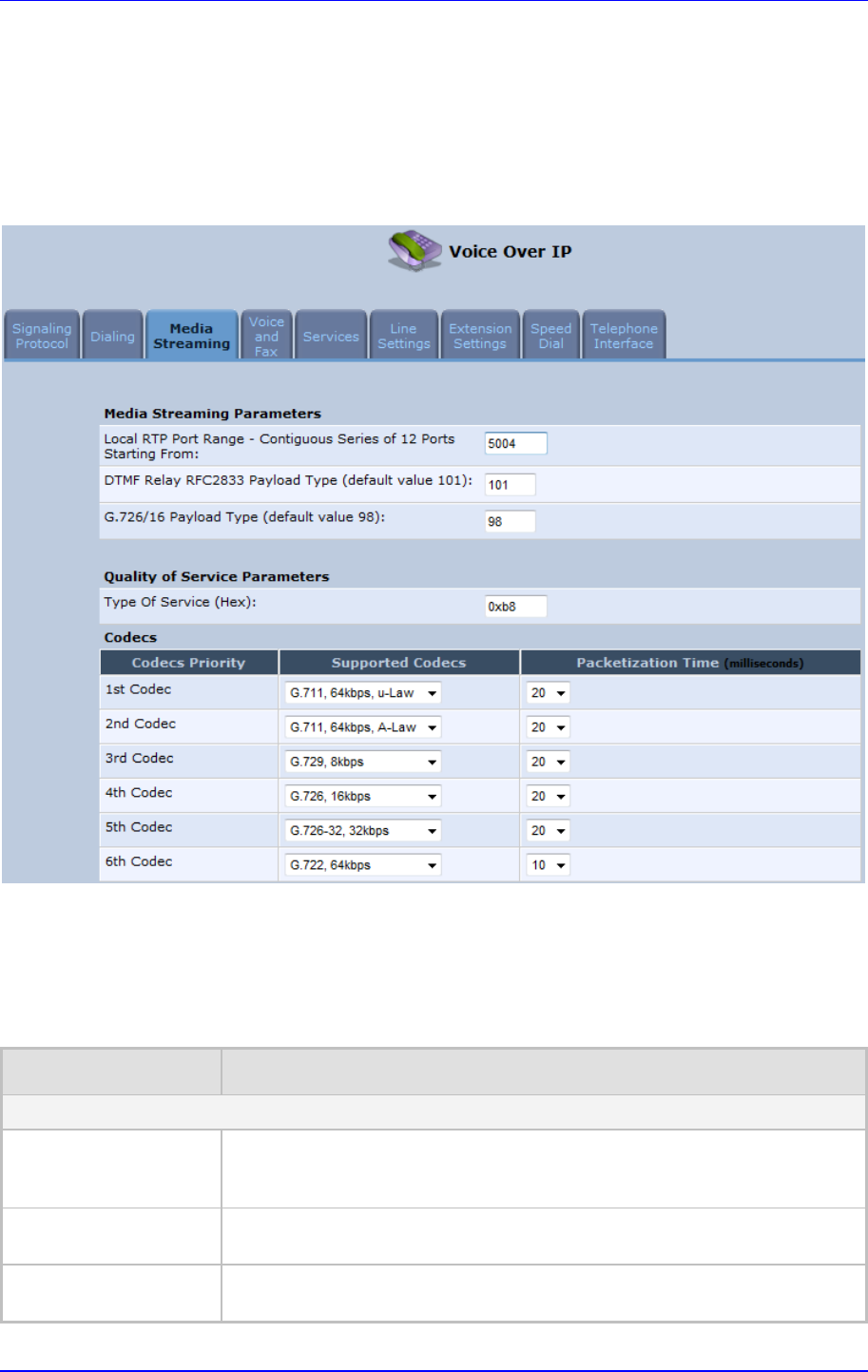
MP252 Multimedia Home Gateway 8. Configuring VoIP Parameters
Version 3.4.0 83 June 2011
8.3 Configuring Media Streaming
The procedure below describes how to configure the media streaming parameters.
¾ To configure media streaming parameters:
In the 'Voice Over IP' screen, click the Media Streaming tab; following screen appears.
Figure 8-4: Media Streaming Tab Screen
4. Configure the parameters, as required. For a description of the parameters displayed on
this screen, see Table 8-4.
5. Click OK to save your settings.
Table 8-4: Media Streaming Tab Parameters Description
Parameter Description
Media Streaming Parameters
Local RTP Port Range -
Contiguous Series of 8
Ports Starting From:
Defines the port range for Real Time Protocol (RTP) voice transport.
DTMF Relay RFC 2833
Payload Type Defines the RTP payload type used for RFC 2833 DTMF relay packets. The
range is 0-255. The default is 101.
G.726/16 Payload Type Defines the RTP payload type used for 16 kbps G.726 packets. The range is
0-255. The default is 98.

MP252 Multimedia Home Gateway 84 Document #: LTRT-23504
User's Manual
Parameter Description
Quality of Service Parameters
Type of Service (Hex) This is a part of the IP header that defines the type of routing service to be
used to tag outgoing voice packets originated from MP252. It is used to
inform routers along the way that this packet should get specific QoS. Leave
this value as 0xb8 (default) if you are unfamiliar with the Differentiated
Services IP protocol parameter.
Codecs
1st - 6th Codec Defines the voice codec. For more information, see 8.3.1 on page 84.
8.3.1 Configuring Codecs
Codecs define the method of relaying voice data. Different codecs have different
characteristics, such as data compression and voice quality. For example, G.723 is a codec
that uses compression, so it is good for use where bandwidth is limited but its voice quality is
not as good compared to other codecs such as the G.711.
8.3.1.1 Supported Codecs
To make a call, at least one codec must be enabled. Moreover, all codecs may be enabled
for best performance. When you start a call to a remote party, your available codecs are
compared against the remote party's to determine the codec used. The priority by which the
codecs are compared is according to their order of appearance in the table (descending
order). To change the priorities, rearrange the codecs in the required order.
If there is no codec that both parties have made available, the call attempt fails. Note that if
more than one codec is common to both parties, you cannot force which of the common
codecs that were found are used by the remote party's client. If you do wish to force the use
of a specific codec, leave only that codec checked.
8.3.1.2 Packetization Time
The Packetization Time is the length of the digital voice segment that each packet holds. The
default is 20 millisecond packets. Selecting 10 millisecond packets reduces the delay but
increases the bandwidth consumption.
8.4 Configuring Voice and Fax
The procedure below describes how to configure the voice and fax parameters.
¾ To configure voice and fax parameters:
1. In the 'Voice Over IP' screen, click the Voice and Fax tab; the following screen appears.
Figure 8-5: Voice and Fax Tab Screen
MP252 Multimedia Home Gateway 8. Configuring VoIP Parameters
Version 3.4.0 85 June 2011
2. Configure the parameters, as required. For a description of the parameters displayed on
this screen, see Table 8-5.
3. Click OK to save your settings.

MP252 Multimedia Home Gateway 86 Document #: LTRT-23504
User's Manual
Table 8-5: Voice and Fax Tab Parameters Description
Parameter Description
Gain Control
Enable Automatic Gain
Control Enables the Automatic Gain Control (AGC) mechanism. The AGC
mechanism adjusts the level of the received signal to maintain a steady
(configurable) volume level.
Automatic Gain Control
Direction Defines the AGC direction (local or remote user).
Note: This parameter appears only if the ‘Enable Automatic Gain Control’
check box is selected.
Target Energy Defines the signal energy value (in dBm) that the AGC attempts to attain.
The range is 0 to -63 dBm. The default value is -19 dBm.
Note: This parameter appears only if the ‘Enable Automatic Gain Control’
check box is selected.
Jitter Buffer
Minimum Delay Defines the initial and minimal delay of the adaptive jitter buffer mechanism,
which compensates for network problems. The value should be set
according to the expected average jitter in the network (in milliseconds). The
default is 35 msec.
Optimization Factor Defines the adaptation rate of the jitter buffer mechanism. Higher values
cause the jitter buffer to respond faster to increased network jitter. The
default is 7.
Silence Compression
Enable Silence
Compression Enables silence compression, which reduces the network bandwidth
consumption. The default is disabled.
Enable G.711/G.726
Comfort Noise
Enables the Comfort Noise generation feature. When enabled and silence is
detected, MP252 transmits a series of parameters called Silence Information
Descriptor (SID), which are used to reproduce the local background noise at
the remote (receiving) side.
Note: This parameter appears only if the ‘Enable Silence Compression’
check box is selected.
Echo Cancellation
Enable Echo
Cancellation Enables (default) echo cancellation (disabling echo cancellation should be
done for testing purposes only).
Fax and Modem Settings
Fax Transport Mode Selects the way fax calls are handled:
9 Transparent = Fax is transferred in-band (like a voice call) - can be
used if the codec is G.711
9 T.38 Relay = Fax is relayed to the remote side according to the T.38
standard
9 Voice Band Data = Switch to G.711 via SIP messaging
9 Bypass = An automatic switch to AudioCodes' proprietary payload
type (102, 103).
Max Rate Defines the maximum fax rate.
2.4 Kbps, 4.8 Kbps, 7.2 Kbps, 9.6 Kbps, 12 Kbps or 14.4 Kbps (default).
Note: This parameter appears only if 'Fax Transport Mode' is set to ‘T.38
Relay’.

MP252 Multimedia Home Gateway 8. Configuring VoIP Parameters
Version 3.4.0 87 June 2011
Parameter Description
Max Buffer Defines the maximum amount of T.38 data stored on the MP252. The valid
range is 128 to 2048. The default is 1024.
Note: This parameter appears only if 'Fax Transport Mode' is set to ‘T.38
Relay’.
Max Datagram Defines the maximum total size of TCP/UDPTL packets that can be received
at the remote gateway. The valid range is 160 to 1020. The default is 320.
Note: This parameter appears only if 'Fax Transport Mode' is set to ‘T.38
Relay’.
Image Data
Redundancy Level
Defines the level for output Image Data (2400…14400 bps).
0 = No redundancy
1 to 3 = Redundancy level
Note: This parameter appears only if 'Fax Transport Mode' is set to ‘T.38
Relay’.
T30 Control Data
Redundancy Level Defines the redundancy level for output T.30 Control Data (300 bps).
0 = No redundancy
1 to 7 = Redundancy level
Note: This parameter appears only if 'Fax Transport Mode' is set to ‘T.38
Relay’.
Fax Relay Jitter Buffer
Delay
Defines the Fax Relay Jitter Buffer.
0 = Adaptive Jitter Buffer. The MP252 sets the Jitter Buffer size
automatically and then adapts it according to network conditions.
1 to 511 = Fixed Jitter Buffer size (in msec).
Note: This parameter appears only if 'Fax Transport Mode' is set to ‘T.38
Relay’.
Error Correction Mode Enables (default) fax error correction mode (ECM).
Note: This parameter appears only if 'Fax Transport Mode' is set to ‘T.38
Relay’.
Fax Bypass Payload
Type
Defines the payload type for fax in Bypass mode.
Note: This parameter appears only if 'Fax Transport Mode' is set to ‘Bypass’.
Modem Transport Mode Selects the way modem calls are handled:
Transparent = Data is transferred in-band (like a voice call). This can be
used if the codec is G.711.
Voice Band Data = Switch to G.711 via SIP messaging.
Bypass = An automatic switch to AudioCodes' proprietary payload type
(102, 103).
Note: If the Fax transport mode is Bypass or VBD, it must match the Modem
transport mode.
Modem Bypass
Payload Type Defines the payload type for modems in Bypass mode.
Note: This parameter appears only if 'Modem Transport Mode' is set
‘Bypass’.
Fax/Modem Bypass
Codec Defines the codec for the VBD and Bypass modes. PCMA (default) or
PCMU.
G.711 64 kbps A-Law
-OR-
G.711 64 kbps u-Law

MP252 Multimedia Home Gateway 88 Document #: LTRT-23504
User's Manual
Parameter Description
CED Transfer Mode By Fax Relay: When MP252 is the receiver side, Switch to Fax relay is
enabled upon CED. This allows a high reliable fax-over-IP call
establishment at the beginning of CED tone.
In Voice Or PCM Bypass: When MP252 is the receiver side, to avoid
possible conflicts with low-speed modems, the CED (ANS) relay by FoIP
protocol may be disabled by setting the CED transfer mode to ‘In Voice
Or PCM Bypass’. In this case, MP252 does not initiate the Fax Relay on
detecting CED tone in absence of CNG, but switches to VBD or remains
in voice mode (depends on the Modem Transport Mode). MP252
switches to FoIP later when it defines exactly that a monitored call is the
fax call (CED and CND or V.21 Preamble).
Enable CNG Detection Enables detection of the fax CNG signal. When the local fax machine
connected to MP252 receives a fax, MP252 switches to T.38 fax relay upon
detection of the CED signal from the remote fax. If the local fax machine
sends a fax, MP252 switches to T.38 only after detecting the CNG signal
from the local side and the CED signal from the remote side. If this check bo
x
is selected, MP252 switches to T.38 relay immediately upon detection of the
CNG signal from the local side, without waiting for the CED signal from the
remote side. The default is disabled.
Switch To Fax Only By
The Answering Side
Typically, switching to fax mode is the responsibility of the answering side.
However, in some cases, the sending machine can also switch to fax mode.
If this check box is marked, the sending machine does not switch to fax, but
allows the answering side to detect the fax and switch to fax mode.
8.5 Configuring Supplementary Services
The procedure below describes how to configure the services parameters.
¾ To configure supplementary services:
1. In the 'Voice Over IP' screen, click the Services tab; the following screen appears.
Figure 8-6: Services Tab Screen
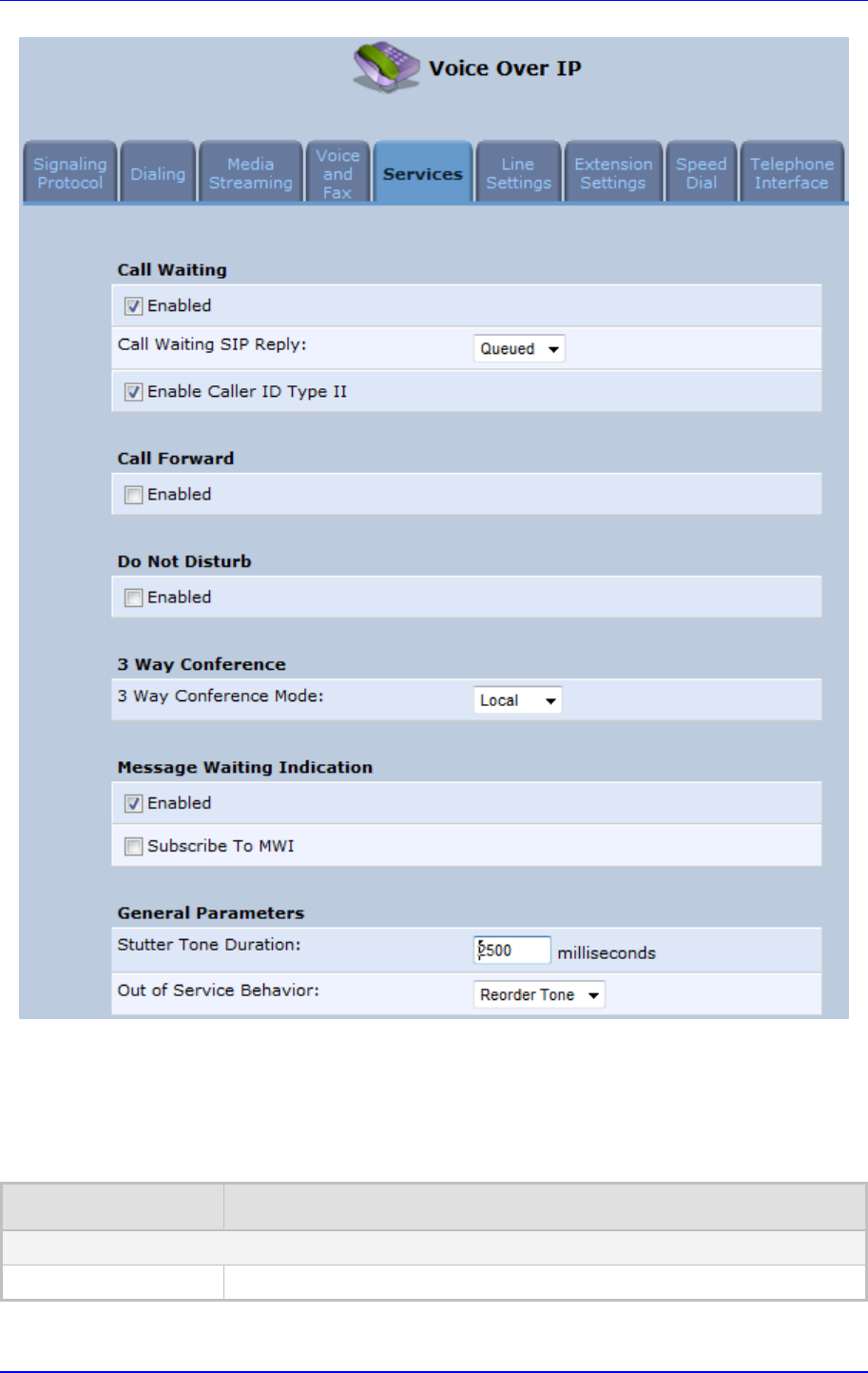
MP252 Multimedia Home Gateway 8. Configuring VoIP Parameters
Version 3.4.0 89 June 2011
2. Configure the parameters, as required. For a description of the parameters displayed on
this screen, see Table 8-6.
3. Click OK to save your settings.
Table 8-6: Services Tab Parameters Description
Parameter Description
Call Waiting
Enabled Enables the Call Waiting feature.

MP252 Multimedia Home Gateway 90 Document #: LTRT-23504
User's Manual
Parameter Description
Call Waiting SIP Reply Defines the SIP response (180 Ringing or 182 Queued - default) sent when
another call arrives while a call is in progress.
Note: This parameter appears only if Call Waiting is enabled.
Enable Caller ID Type II Enables caller ID of a waiting call (Called Caller ID type 2).
Note: This parameter appears only if Call Waiting is enabled.
Call Forward
Enabled Enables call forwarding. The Call Forward feature permits a user to redirect
incoming calls addressed to another number. The user’s ability to originate
calls is unaffected by Call Forward.
Note: The Call Forward feature is functional only when MP252 is registered
to a proxy.
Call Forward Type Defines the type of call forwarding:
Unconditional: Incoming calls are forwarded independently of the status
of the endpoint.
Busy: Incoming calls are forwarded only if the endpoint is busy, i.e., if all
lines are active.
No Reply: Incoming calls are forwarded only if the endpoint does not
answer before a user-defined timeout (see ‘Time for No Reply Forward’
parameter).
Note: This parameter appears only if Call Forward is enabled.
Time for No Reply
Forward Defines the timeout after which the call is forwarded if the endpoint does not
answer. If you specify 5 seconds, for example, and 'No Reply' is selected fo
r
parameter 'Call Forward Type' (see above), incoming calls are forwarded
only after 5 seconds lapse.
Note: This parameter is available only when ‘No Reply’ is selected for the
parameter 'Call Forward Type'.
Key Sequence The default is *72 but users can modify to any sequence of up to 2 digits, i.e.,
*n or *nm.
Do Not Disturb
Enabled Enables the Do Not Disturb (DND) feature. This feature allows you to
prevent incoming calls from ringing at your phone. When enabled, callers
receive a busy signal or an announcement. The DND is activated using the
phone keypad. The default is disabled.
Key Sequence Defines the key sequence to activate and deactivate the DND feature.
3 Way Conference
3 Way Conference
Mode Selects how 3-way conference calls are handled:
Local: locally by MP252
Remote: by a remote media server (RFC 4240)
Media Server Address The address of the remote media server that handles conference calls.
Note: This parameter is available only when ‘Remote’ is selected for the
parameter '3 Way Conference Mode'.

MP252 Multimedia Home Gateway 8. Configuring VoIP Parameters
Version 3.4.0 91 June 2011
Parameter Description
Message Waiting Indication
Enabled If a user has an unheard voice mail message, a stutter dial tone is heard
when the user picks up the phone. In addition, MP252 generates an FSK
signal to the phone to indicate that a message is waiting. If the telephone
connected to MP252 supports this feature, an MWI ‘envelope icon’ is
displayed.
Subscribe to MWI Select this check box if you must register with a MWI subscriber server. If so,
configure the three parameters below.
MWI Server IP Address
or Host Name Defines the IP address or host name of the MWI server.
Note: This parameter is available only when the check box 'Subscribe to
MWI' is selected.
MWI Server Port Defines the port number of the MWI server.
Note: This parameter is available only when the check box 'Subscribe to
MWI' is selected.
MWI Subscribe
Expiration Time Defines the interval between registrations.
Note: This parameter is available only when the check box 'Subscribe to
MWI' is selected.
General Parameters
Stutter Tone Duration When you enable message waiting and an unheard message exists, a stutte
r
tone is played to the phone for the duration configured by this parameter
and/or when you activate the call forwarding feature (see Section 10.6 on
page 103).
Out of Service Behavior Defines the tone which is played instead of a dial tone if the user configured a
registrar IP and the registration failed. When the Reorder tone is selected, a
Reorder tone is played instead of a dial tone. If “No Tone” is selected, then no
tone is played.
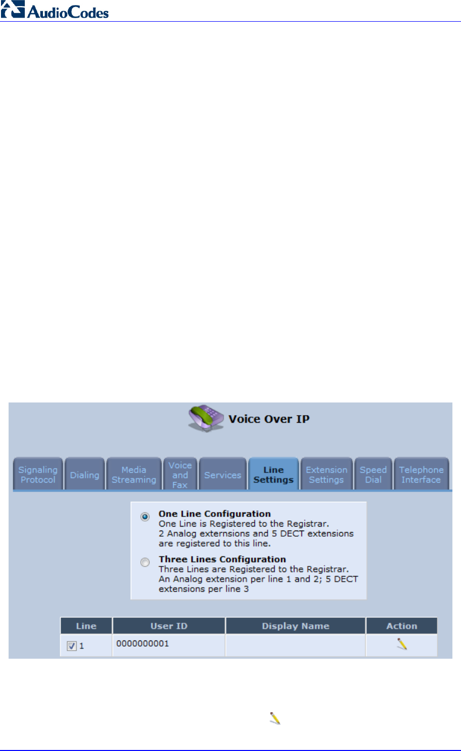
MP252 Multimedia Home Gateway 92 Document #: LTRT-23504
User's Manual
8.6 Configuring Line Settings
Before you can make phone calls, you need to configure lines. Lines are SIP logical ID
numbers (i.e., telephone numbers), which are registered to the SIP proxy server, and for
which you are charged for calls you make on it.
MP252 supports two line-configuration modes:
One-Line Configuration: In this mode, only one line is configured to represent all the
physical telephone extensions on MP252 (i.e., two analog phones and five DECT
handsets):
• When you receive an incoming call, all the extensions on the line ring, and you can
answer from any one of them. When you do answer, the other extensions stop
ringing.
• If you receive another incoming call when you already have an established call on
one extension, all the idle extensions ring, and the busy extension hears a call
waiting tone.
• You can make outgoing calls from any of the extensions.
• You can make multiple concurrent calls (i.e., each extension makes a call to a
different destination and at the same time).
Three-Lines Configuration: In this mode, three lines can be configured:
• Line 1 for the analog telephone connected to the MP252 port labeled Phone 1
• Line 2 for the analog telephone connected to the MP252 port labeled Phone 2
• Line 3 for all the DECT handsets (up to five)
¾ To configure lines:
1. In the 'Voice Over IP' screen, click the Line Settings tab; the following screen appears.
Figure 8-7: Line Settings Tab Screen
2. Select the configuration mode options – One Line Configuration or Three Lines
Configuration; the table lists the lines according to the selected line configuration
mode.
3. For each line, click the corresponding Edit icon to configure the line; the following
screen appears:
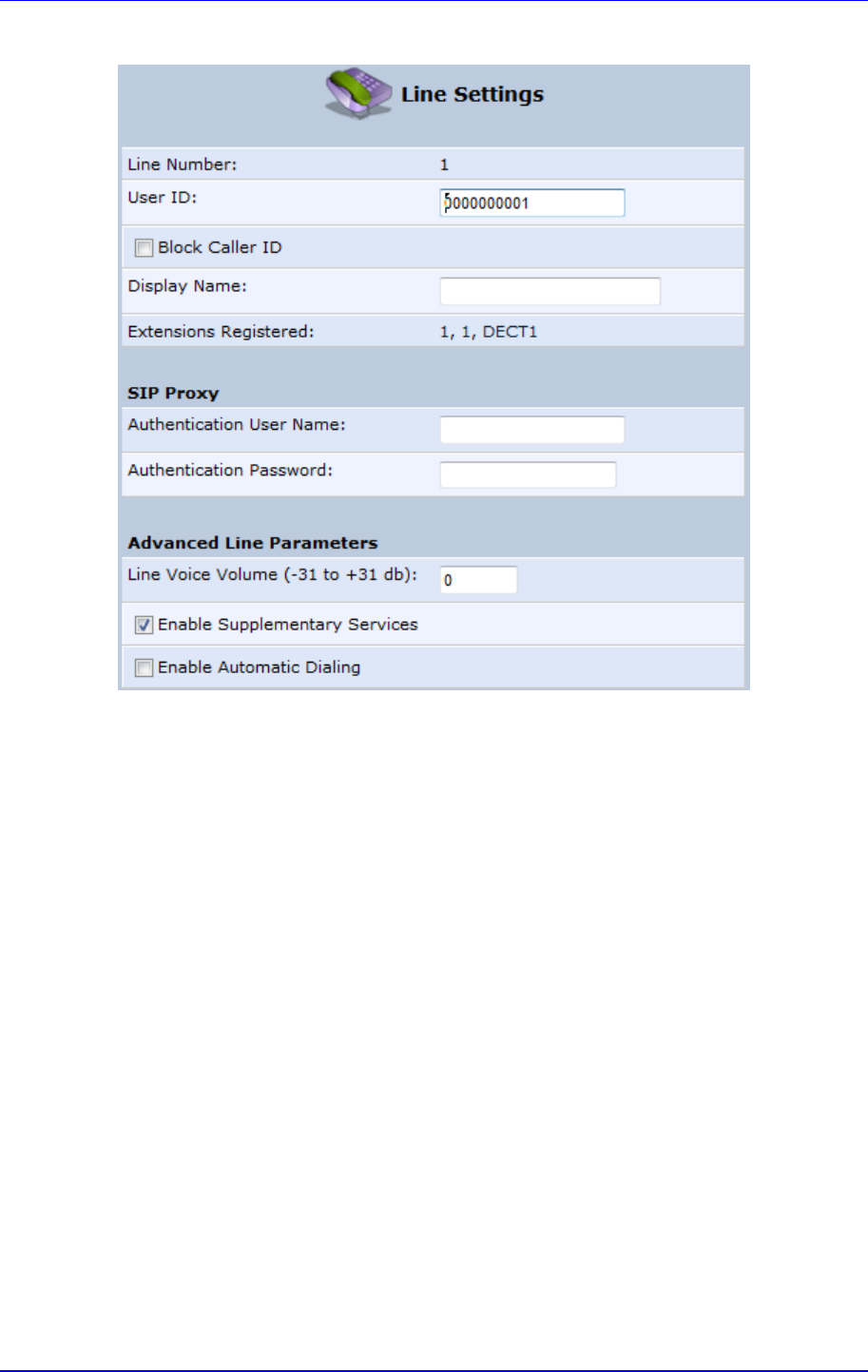
MP252 Multimedia Home Gateway 8. Configuring VoIP Parameters
Version 3.4.0 93 June 2011
Figure 8-8: Line Settings Screen for a New Line
The screen displays the following read-only information:
• Line Number: line number
• Extensions Registered: extensions registered to this line
4. In the ‘User ID’ field, enter phone's VoIP user ID used for identification to initiate and
accept calls.
5. To hide the phone’s ID from the remote party, select the ‘Block Caller ID’ check box.
6. In the ‘Display Name’ field, enter a name to intuitively identify the line. This is also
displayed to remote parties as your caller ID.
7. Under the SIP Proxy group, define the SIP proxy server:
a. In the ‘Authentication User Name’ field, enter the user name received from your
VoIP service provider. This is used when sending a response to Unauthorized or
Proxy Authentication Requested (401/407).
b. In the ‘Authentication Password’ field, enter the password received from your VoIP
service provider. This is used when sending a response to Unauthorized or Proxy
Authentication Requested (401/407).
8. In the ‘Line Voice Volume’ field, enter the voice volume of the line (i.e., the gain from the
network toward the local phone). The default is 0 dB.
9. To enable supplementary services on this line, select the ‘Enable Supplementary
Services’ check box.
10. To enable automatic dialing (which automatically dials a user-defined phone number
when the line is off-hooked longer than a user-defined time), do the following:
c. Select the ‘Enable Automatic Dialing’ check box.

MP252 Multimedia Home Gateway 94 Document #: LTRT-23504
User's Manual
d. In the ‘Automatic Dialing Timeout’ field, enter the time after which automatic dialing
is activated if the user has not started dialing before this timeout. When set to 0,
automatic dialing is performed immediately.
e. In the ‘Automatic Dialing Destination’ field, enter the destination that is
automatically dialed. This can be a phone number or a domain name (for example,
user@101.10.13.2 or user@domain name).
11. Click OK to save your settings.
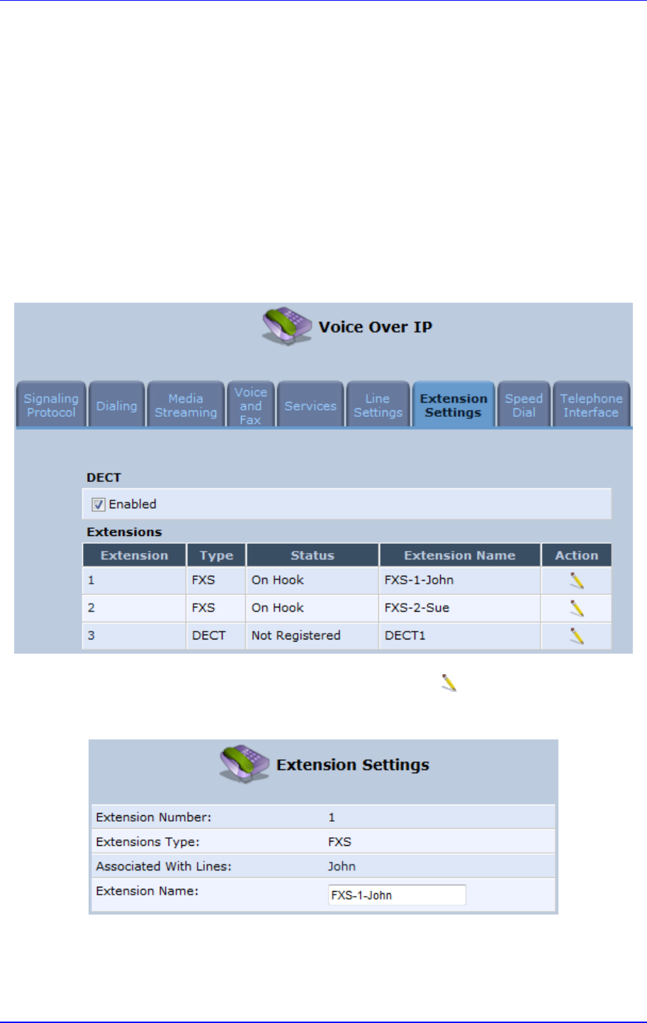
MP252 Multimedia Home Gateway 8. Configuring VoIP Parameters
Version 3.4.0 95 June 2011
8.7 Configuring Line Extensions
Extensions are the physical telephony extensions on MP252. These can either be FXS ports
(for analog telephones) or cordless DECT handsets.
Once you have defined your lines, you can do the following:
Define an arbitrary name for each extension (to help you identify the extension).
Initiate the registration process of the lines with the proxy server (and DECT with base
unit)
¾ To configure line extensions:
1. In the 'Voice Over IP' screen, click the Extension Settings tab; the following screen
appears.
Figure 8-9: Extension Settings Tab Screen
2. For each line extension, click the corresponding Edit icon to define a name for the
extension; the following screen appears:
Figure 8-10: Extension Settings Screen
3. Click OK to save your settings.
¾ To register the lines:
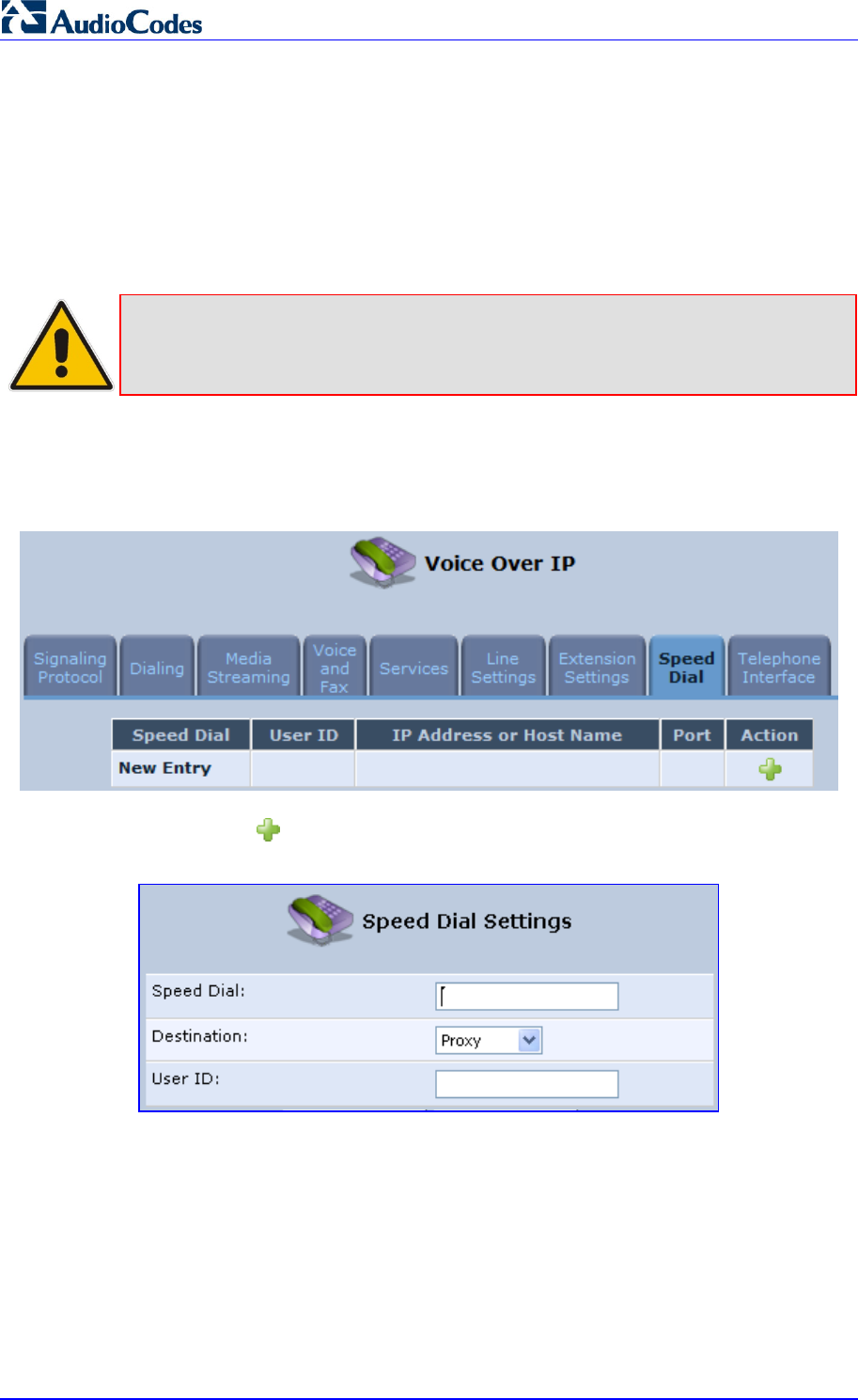
MP252 Multimedia Home Gateway 96 Document #: LTRT-23504
User's Manual
4. In the ‘Extension Settings Tab; screen; click the Register button.
8.8 Configuring Speed Dialing
Use the 'Speed Dial Settings' screen to associate a called party's contact parameters
(including the IP address of his/her ATA and Line ID) with a number that you'll dial to call the
called part. The number of speed-dialing codes that can be defined is unlimited. Use the
screen to define a destination type: Proxy, Local Line or Direct Call.
Note: When connecting MP252 to a World-Wide SIP Server (see 'Connecting
MP252's VoIP to a VoIP Service Provider' on page 99), you don't need to
configure 'Speed Dial Settings'.
¾ To configure speed dialing:
1. In the 'Voice Over IP' screen, click the Speed Dial tab; the following screen appears:
Figure 8-11: Speed Dial Tab Screen
2. Click the New icon; the 'Speed Dial Settings' screen appears.
Figure 8-12: Speed Dial Settings Screen (Proxy Destination)
3. In the ‘Speed Dial’ field, enter the shortcut number (i.e., speed dial) which you dial to call
the party defined below.
4. From the ‘Destination’ drop-down list, select the destination type.
• Proxy: If you select this option (as shown in the figure above), then in the ‘User ID’
field, enter the user ID to call.
• Local Line: If you select this option, then from the ‘Line’ drop-down list, select the
configured local line on your MP252.
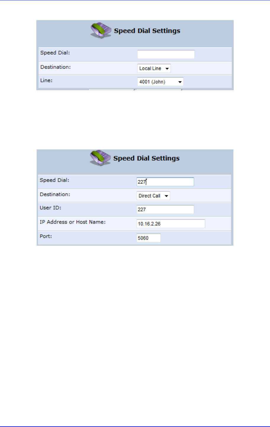
MP252 Multimedia Home Gateway 8. Configuring VoIP Parameters
Version 3.4.0 97 June 2011
Figure 8-13: Speed Dial Settings Screen (Local Line Destination)
• Direct Call: if you select this option, then configure the following:
a. In the ‘User ID’ field, enter the user ID to call.
b. In the ‘IP Address or Host Name’ field, enter the remote party's IP address or
host name.
c. In the ‘Port’ field, enter the SIP UDP or TCP port of the remote party.
Figure 8-14: Speed Dial Settings Screen (Direct Call Destination)
5. Click OK to save your settings.
8.9 Enabling Polarity Reversal
The procedure below describes how to enable polarity reversal. When this feature is
enabled, the analog port (FXS) interface polarity is reversed to indicate the start of a VoIP
session, and is reversed back when the VoIP session ends.
¾ To enable polarity reversal:
1. In the 'Voice Over IP' screen, click the Telephone Interface tab; the following screen
appears:
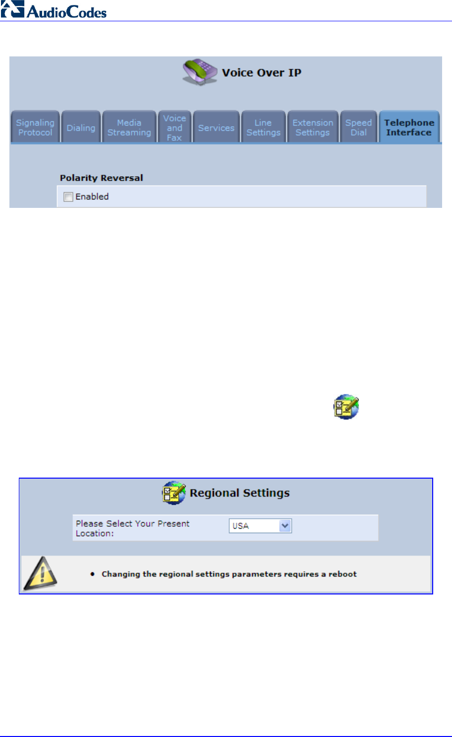
MP252 Multimedia Home Gateway 98 Document #: LTRT-23504
User's Manual
Figure 8-15: Telephone Interface Tab Screen
2. Select the 'Enabled' check box to enable the Polarity Reversal feature.
3. Click OK to apply your settings.
8.10 Selecting Regional Settings for Analog Lines
The behavior and parameters of analog telephones lines vary between countries. The set of
Call Progress Tones, the protocol used for caller ID and the analog line impedance are all
location-specific. MP252 enables users to select the country they reside in and MP252
automatically selects the correct regional settings.
¾ To select your present location:
1. In the 'Advanced' screen, click the Regional Settings icon; the 'Regional
Settings' screen appears.
2. Select the country from the drop-down list. If your current location is not listed, contact
your service provider.
Figure 8-16: Regional Settings Screen
3. Click OK.
4. Reboot MP252 for your settings to take effect.
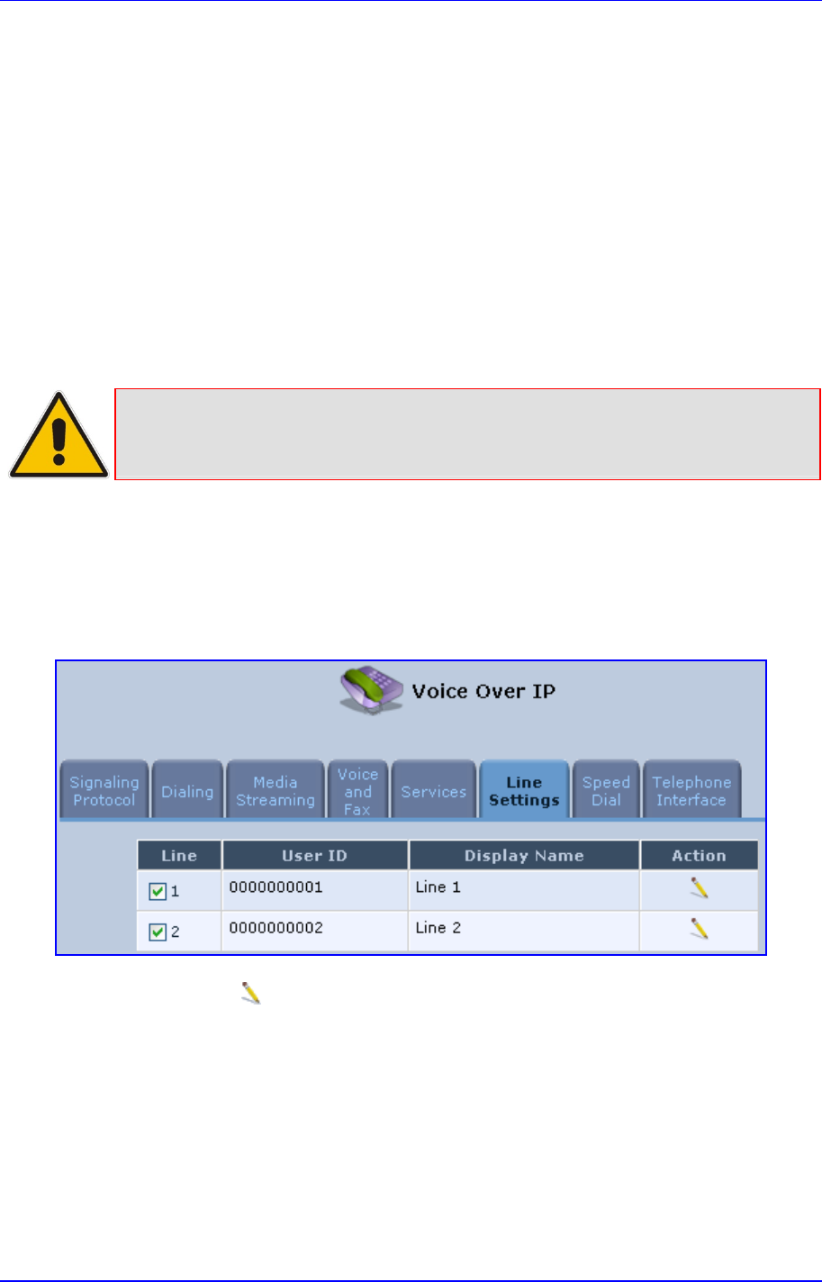
Version 3.4.0 99 July 2011
MP252 Multimedia Home Gateway 9. Connecting MP252 to an ITSP
9 Connecting MP252 to an ITSP
The MP252 VoIP capabilities allow you to connect to a remote SIP server or Internet
Telephony Service Provider (ITSP) and conduct phone calls over the Internet (i.e., VoIP).
This chapter describes how to place a VoIP call utilizing MP252's VoIP capabilities over a
SIP server. Verify that your MP252 and telephone are correctly connected and that your
WAN connection is up.
9.1 Opening a SIP Account
Before you can connect to a SIP server, it is necessary that you obtain a SIP account.
9.2 Configuring VoIP Parameters
Note: This section describes the minimal set of changes required to connect to a VoIP
Service Provider. Other configuration changes might be required to connect to
some Service Providers.
¾ To configure VoIP parameters:
1. In the menu bar, click the menu Voice Over IP; the ‘Voice Over IP’ screen appears.
2. Click the Line Settings tab. Enable only the lines that you are using, by selecting the
check box, and then click Apply.
Figure 9-1: Voice Over IP - Line Settings Screen
3. Click the Edit icon corresponding to the line that you want to configure (example, line
1); the ‘Line Settings’ screen appears. Use the configuration values provided by your
ISP to configure the parameters in this screen.
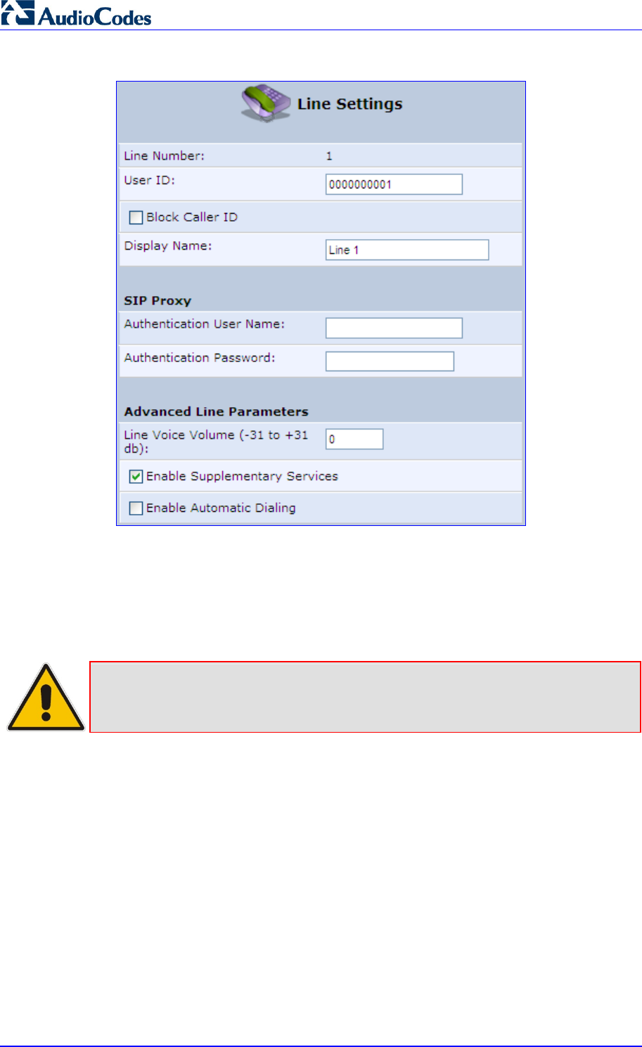
MP252 Multimedia Home Gateway 100 Document #: LTRT-23504
User's Manual
Figure 9-2: VoIP - Line Settings - Defining a New Line
4. Click the Signaling Protocol tab and then select the ‘Use SIP Proxy’ check box (see
'Configuring Signaling Protocol Parameters' on page 70).
5. In the field ‘Proxy IP Address or Host Name’, define the ISP’s SIP proxy, provided by the
ISP (see 'Configuring Signaling Protocol Parameters' on page 70).
6. Click OK or Apply to complete the VoIP configuration.
Note: To verify successful registration with the proxy server, ensure that the Phone
LED is lit green or in the Voice over IP tab (System Monitoring menu), the
entry ‘SIP Registration’ displays “Registered” for the configured lines.

Version 3.4.0 101 July 2011
MP252 Multimedia Home Gateway 10. Making VoIP Calls with your Analog Telephones
10 Making VoIP Calls with your Analog
Telephones
Analog telephone users that are connected to MP252 can place calls, put calls on hold,
transfer calls, and establish three-way conferences. This chapter describes how to perform
these operations.
Note: For information on using the DECT phone, see Part II.
10.1 Making a Call
The procedure below describes how to make a call.
¾ To make a call:
1. Pick up the phone.
2. Make sure that you can hear a dial tone
3. Dial the remote party's number or the user-defined speed dial number (if configured in
Section 8.8 on page 96).
10.2 Answering a Waiting Call
The procedure below describes how to answer a waiting call. This depends on how you
configured the flash-hook functionality, using the ‘Flash keys sequence style’ parameter in
Section 8.2 on page 79. To enable call waiting, see Section 8.5 on page 88.
¾ To answer a waiting call when 'Flash only' is set:
1. When you hear a call waiting tone (during a call), press the flash key button on your
phone; the active call is put on hold and switches to the waiting call.
2. To return to the original call, press the flash button again. You can toggle from one party
to another by pressing the flash button.
¾ To answer a waiting call when 'Flash + digits sequence' is set:
1. When you hear the call waiting tone (during a call), press the flash key button on your
phone and then press the '1' key; the original call is put on hold and switches to the
waiting call.
2. To return to the original call, press flash + 1 again. You can toggle from one party to
another by pressing flash + 1.

MP252 Multimedia Home Gateway 102 Document #: LTRT-23504
User's Manual
10.3 Placing a Call on Hold
The procedure below describes how to place a call on hold. This depends on how you
configured the flash-hook functionality, using the ‘Flash keys sequence style’ parameter in
Section 8.2 on page 79.
¾ To place the remote party on hold when 'Flash only' is set:
During a call, press the flash key button on your phone; a dial tone is heard. At this point
you can initiate a second call by dialing another party's number.
Note: If you press the flash key button again before the second party answers, the
call is established with the original call. If, however, the second party answers
and you press the flash key button, a 3-way conference is established.
¾ To place the remote party on hold when 'Flash + digits sequence' is set:
1. Press the flash key button key and then press the '1' key on your phone; the phone plays
a dial tone. At this point you can initiate a second call by dialing another party's number.
2. To cancel the hold state and resume the previous phone call, press the flash key button
and then press '1'.
10.4 Transferring a Call
The procedure below describes how to transfer an established call to another destination.
This depends on how you configured the flash-hook functionality, using the ‘Flash keys
sequence style’ parameter in Section 8.2 on page 79.
¾ To transfer a call when 'Flash only' is set:
1. During a call with party B, press the flash key button on your phone; party B is placed on
hold and a dial tone is heard.
2. Dial party C's number.
3. You can wait for C to answer or not.
4. On-hook your phone; party B is now transferred to party C.
¾ To transfer a call when 'Flash + digits sequence' is set:
1. During a call with party B, press the flash key button and then press the '1' key on the
phone; party B is placed on hold and a dial tone is heard.
2. Dial party C's number.
3. You can wait for C to answer or not.
4. Press the flash key button key and then press '2'; party B is transferred to party C (and a
warning tone is heard).

MP252 Multimedia Home Gateway 10. Making VoIP Calls with your Analog Telephones
Version 3.4.0 103 June 2011
10.5 Establishing a 3-Way Conference Call
The procedure below describes how to establish a 3-way conference call. The method for
doing this depends on how you configured the flash-hook functionality, using the ‘Flash keys
sequence style’ parameter in Section 8.2 on page 79. In addition, to configure 3-way
conferencing, see Section 8.5 on page 88.
¾ To establish a 3-way conference call when 'Flash only' is set:
1. During a call with party B, press the flash key button on your phone; Party B is placed on
hold and a dial tone is heard.
2. Dial party C's number and wait until the call is established.
3. Press the flash key button again to add parties B and C to a 3-way conference call.
4. To end the 3-way conference call, on-hook your phone (or alternatively, press the flash
key button again).
¾ To establish a 3-way conference call when 'Flash + digits sequence' is
set:
1. During a call with party B, press the flash key button on your phone and then press the
'1' key; Party B is placed on hold and a dial tone is heard.
2. Dial party C's number and wait until the call is established.
3. Press the flash key button and then press the '3' key to add B and C to a 3-way
conference call.
4. To end the 3-way conference call, on-hook your phone (or alternatively, press the flash
key button and then press the '3' key).

MP252 Multimedia Home Gateway 104 Document #: LTRT-23504
User's Manual
10.6 Forwarding Calls to another Phone
The procedure below describes how to automatically forward incoming (received) calls to
another phone. Before you can forward calls, you need to enable and configure call
forwarding as described in Section 8.5 on page 88.
Note: The Call Forward feature is functional only when MP252 is registered to a proxy.
¾ To forward calls to another phone:
1. Pick up the phone and make sure that you can hear a dial tone.
2. Dial the call forward key sequence (according to your configuration), for example, *32; a
dial tone is heard.
3. Dial the number of the phone to where you want calls forwarded; a stutter tone is heard.
4. Replace the receiver; all incoming calls are forwarded. Every time you pick up the
phone receiver, a stutter tone is played (for the length of time, as you configured for the
'Stutter Tone Duration' parameter).
¾ To deactivate call forwarding:
1. Pick up the phone; a stutter tone is heard.
2. Dial the call forward key sequence.
3. Replace the receiver.
4. To make sure that call forwarding has been de-activated, pick up the phone again; a
regular dial tone should be heard (not the stutter tone).

Version 3.4.0 105 July 2011
MP252 Multimedia Home Gateway 11. Quality of Service
11 Quality of Service
Network-based applications and traffic are growing at a high rate, producing an
ever-increasing demand for bandwidth and network capacity. For obvious reasons,
bandwidth and capacity cannot be expanded infinitely, requiring that bandwidth-demanding
services be delivered over existing infrastructure, without incurring additional, expansive
investments.
The next logical means of ensuring optimal use of existing resources are Quality of Service
(QoS) mechanisms for congestion management and avoidance. QoS refers to the capability
of a network device to provide better service to selected network traffic. This is achieved by
shaping the traffic and processing higher priority traffic before lower priority traffic.
As QoS is dependent on the "weakest link in the chain", failure of but a single component
along the data path to assure priority packet transmission can easily cause a VoIP call or a
Video on Demand (VoD) broadcast to fail miserably. QoS must therefore obviously be
addressed end-to-end.
The following are the potential bottleneck areas that need be taken into consideration when
implementing an end-to-end QoS-enabled service.
The Local Area Network: LANs have finite bandwidth, and are typically limited to 100
Mbps. When given the chance, some applications consume all available network
bandwidth. In business networks, a large number of network-attached devices can lead
to congestion. The need for QoS mechanisms is more apparent in wireless LANs,
where bandwidth is even more limited (typically no more than 20 Mbps on 802.11g
networks).
The Broadband Router: All network traffic passes through and is processed by the
broadband router. It is therefore a natural focal point for QoS implementation. Lack of
sufficient buffer space, memory or processing power, and poor integration among
system components can result in highly undesirable real-time service performance. The
only way to assure high QoS is the use of proper and tightly-integrated router operating
system software and applications, which can effectively handle multiple real-time
services simultaneously.
The Broadband Connection: Typically, the most significant bottleneck of the network,
this is where the high speed LAN meets limited broadband bandwidth. Special QoS
mechanisms must be built into routers to ensure that this sudden drop in connectivity
speed is taken into account when prioritizing and transmitting real-time service-related
data packets.
The Internet: Internet routers typically have a limited amount of memory and bandwidth
available to them, so that congestions may easily occur when links are over-utilized,
and routers attempt to queue packets and schedule them for retransmission. One must
also consider the fact that while Internet backbone routers take some prioritization into
account when making routing decisions, all data packets are treated equally under
congested conditions.
Note: For recommended QoS configuration see Section 11.7 on page 120.
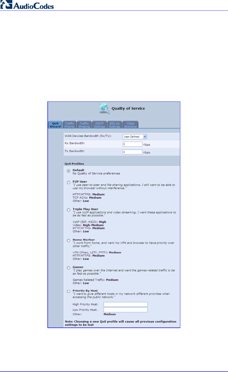
MP252 Multimedia Home Gateway 106 Document #: LTRT-23504
User's Manual
11.1 QoS Wizard
The QoS wizard allows you to configure your QoS parameters according to predefined
profiles, with just a few clicks. A chosen QoS profile automatically defines QoS rules, which
you can view and edit in the rest of the QoS tab screens.
The QoS wizard also allows you to define the WAN bandwidth.
¾ To use the QoS Wizard:
1. From the menu bar, click the QoS menu link; the ‘Quality of Service’ screen appears
with the QoS Wizard tab selected by default.
Figure 11-1: QoS Wizard Tab Screen
2. Define bandwidth limitation. From the 'WAN Devices Bandwidth (Rx/Tx)' drop-down list,
select ‘User Defined’ if you want to define specific Rx and Tx bandwidth limitations, or
select the Rx/Tx optional values provided in the drop-down list.

MP252 Multimedia Home Gateway 11. Quality of Service
Version 3.4.0 107 June 2011
3. In the QoS Profiles group, select a QoS profile.
4. Click OK.
Note: Selecting a new QoS profile deletes all previous QoS settings.
11.2 Traffic Shaping
Traffic Shaping is the solution for managing and avoiding congestion where a high speed
LAN meets limited broadband bandwidth. A user may have, for example, a 100 Mbps
Ethernet LAN with a 100 Mbps WAN interface router. The router may communicate with the
ISP using a modem with a bandwidth of 2 Mbps. This typical setup makes the modem,
having no QoS module, the bottleneck. The router sends traffic as fast as it is received, while
its well-designed QoS algorithms are left unused. Traffic shaping limits the bandwidth of the
router, artificially forcing the router to be the bottleneck.
A traffic shaper is essentially a regulated queue that accepts uneven and/or bursty flows of
packets and transmits them in a steady, predictable stream so that the network is not
overwhelmed with traffic.
While Traffic Priority allows basic prioritization of packets, Traffic Shaping provides more
sophisticated definitions such as:
Bandwidth limit for each device
Bandwidth limit for classes of rules
Prioritization policy
TCP serialization on a device
You can also define QoS traffic shaping rules for a default device. These rules are used on a
device that has no definitions of its own. This enables the definition of QoS rules on Default
WAN, for example, and their maintenance even if the PPP or bridge device over the WAN is
removed.
MP252 also supports dynamic traffic shaping during a call. Traffic shaping is critical in
residential VoIP gateways because of the bottleneck created in the ADSL or Cable modem,
mainly in the upload direction. Dynamic traffic shaping ensures a minimum bandwidth for
VoIP calls. Without dynamic traffic shaping, traffic shaping limits the bandwidth at all times,
even if the user is not making a VoIP call and therefore, the service provider needs to
configure the QoS traffic shaping transmit (Tx) bandwidth according to the user's specific
upload bandwidth. Configuring a lower value results in a lower upload bandwidth (not only
during VoIP calls).
Dynamic traffic shaping enables the service provider to configure two upload traffic shaping
bandwidth parameters:
"Tx Bandwidth" - for all traffic
"Tx Bandwidth during Call" - for VoIP calls
MP252 normally uses the "Tx Bandwidth" value. When the user makes a VoIP call (i.e. any
phone/s connected to MP252 is ringing or off-hook), MP252 switches to use the "Tx
Bandwidth during Call" value.
11.2.1 Device Traffic Shaping
The procedure below describes how to configure traffic shaping.
¾ To add a traffic shaping device:
1. From the menu bar, click the QoS menu, and then click the Traffic Shaping tab.
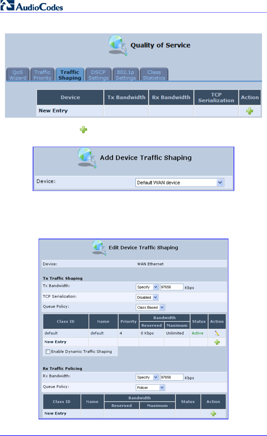
MP252 Multimedia Home Gateway 108 Document #: LTRT-23504
User's Manual
Figure 11-2: Quality of Service – Traffic Shaping Screen
2. Click the New icon; the 'Add Device Traffic Shaping’ screen appears.
Figure 11-3: Add Device Traffic Shaping Screen
3. From the ‘Device’ drop-down list, select the device for which you want to shape traffic.
The list includes all interfaces (e.g., All LAN Devices, All WAN Devices) and VPNs such
as PPoE, PPTP and L2TP (if defined). For example, select 'WAN Ethernet', and then
click OK; the ’Edit Device Traffic Shaping’ screen appears.
Figure 11-4: Edit Device Traffic Shaping Screen

MP252 Multimedia Home Gateway 11. Quality of Service
Version 3.4.0 109 June 2011
4. Under the Tx Traffic Shaping group, from the ‘Tx Bandwidth’ drop-down list, select
‘Specify’ and define the MP252’s maximum transmission bandwidth rate in the
corresponding field. The purpose is to limit the bandwidth of the WAN interface to that of
the weakest outbound link, for instance, the DSL speed provided by the ISP. This forces
MP252 to be the network bottleneck, where sophisticated QoS prioritization can be
performed. If the device’s bandwidth is not limited correctly, the bottleneck is an
unknown router or modem on the network path, rendering MP252 QoS useless. To
configure unlimited bandwidth, select ‘Unlimited’.
5. Under the Rx Traffic Policing group, from the ‘Rx Bandwidth’ drop-down list, select
‘Specify’ and define the MP252’s maximum receive bandwidth rate in the corresponding
field. This limits MP252’s bandwidth receipt rate to that of the DSL modem.
6. From the ‘TCP Serialization’ drop-down list, select whether to enable TCP serialization.
The screen refreshes, displaying the ’Maximum Delay’ field. This allows you to define
the maximum allowed transmission time frame (in milliseconds) of a single packet. Any
packet that requires a longer time to be transmitted is fragmented to smaller sections.
This avoids transmission of large, bursty packets that may cause delay or jitter for
real-time traffic such as VoIP.
7. Select the ‘Enable Dynamic Traffic Shaping’ check box if you want to configure traffic
shaping specifically for VoIP calls (see Section 11.2 on page 107). When selected, the
‘Tx Bandwidth During VoIP Call’ field appears. Enter the bandwidth for VoIP calls.
MP252 normally uses the "Tx Bandwidth" parameter value. When the user makes a
VoIP call (i.e. any phone connected to MP252 is ringing or off-hook), MP252 switches to
use the "Tx Bandwidth during Call" parameter value.
11.2.2 Shaping Classes
The bandwidth of a device can be divided to reserve constant portions of bandwidth to
user-defined traffic types. Such a portion is known as a Shaping Class. When not used by its
user-defined traffic type or owner (for example, VoIP), the class is then available to all other
traffic. However when needed, the entire class is reserved solely for its owner. Moreover, you
can limit the maximum bandwidth that a class can use even if the entire bandwidth is
available.
When a shaping class is defined for a specific traffic type, two shaping classes are created.
The second class is the 'Default Class', responsible for all the packets that do not match the
defined shaping class or any other classes that may be defined on the device. This can be
viewed in the Class Statistics screen.
¾ To add a shaping class:
1. From the menu bar, click the QoS menu, and then click the Traffic Shaping tab.
2. Click the Edit icon corresponding to the added Device (e.g., WAN); the 'Edit Device
Traffic Shaping' screen appears.
3. Under the Tx Traffic Shaping group, click the New icon; the 'Add Shaping Class'
screen appears.
Figure 11-5: Add Shaping Class Screen
4. In the ‘Name’ field, enter a name for the class, and then click OK; the 'Edit Device Traffic
Shaping' screen appears.
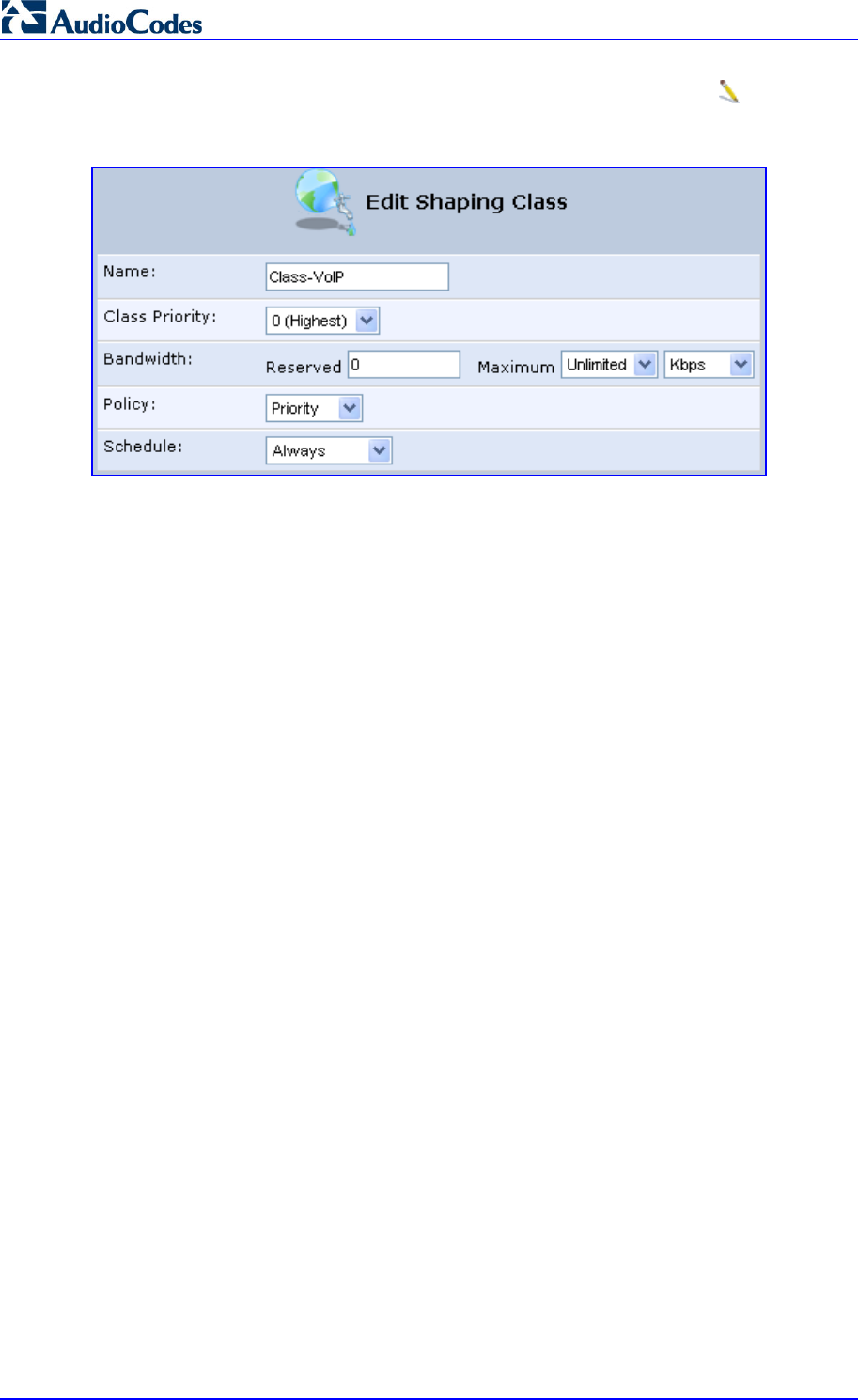
MP252 Multimedia Home Gateway 110 Document #: LTRT-23504
User's Manual
5. Edit the newly added shaping class, by clicking the corresponding Edit icon; the 'Edit
Shaping Class' screen appears.
Figure 11-6: Edit Shaping Class
6. In the ‘Name’ field, modify the class name, if required.
7. From the ‘Class Priority’ drop-down list, select the priority level for the class, where zero
is the highest and seven the lowest.
8. In the ‘Bandwidth’ field, define the bandwidth for the class:
• Reserved: reserved (i.e., guaranteed) bandwidth (Committed Information Rate /
CIR) in kbps.
• Maximum: specify the maximum bandwidth
9. From the ‘Policy’ drop-down list, select the policy for routing packets within the class:
• Priority: Priority queuing uses multiple queues so that traffic is distributed among
queues based on priority. This priority is defined according to packet priority, which
can be defined explicitly by a DSCP value or an 802.1p value.
• FIFO: First In First Out. This priority queue ignores any previously-marked packet
priority.
• Fairness: The fairness algorithm ensures no starvation by granting all packets a
certain level of priority.
• RED: Random Early Detection. Utilizes statistical methods to drop packets in a
‘probabilistic’ way before queues overflow. Dropping packets in this way slows a
source down enough to keep the queue steady and reduces the number of packets
that would be lost when a queue overflows and a host is transmitting at a high rate.
10. From the ‘Schedule’ drop-down list, select the scheduler rule (defined in Section 4.5.1
on page 43) that defines the time segments during which the class can be active. By
default, the class is always active.
11. Click OK to save your settings.
11.2.2.1 Class Rules
Class rules define which packets belong to the class. Without class rules, the shaping class
has no effect. Each class can have outbound and inbound rules for outgoing and incoming
traffic respectively. For example, you can define that all outgoing packets from computer A in
your LAN belong to your VoIP class. These packets are limited to the class settings
(bandwidth, schedule, etc.). In addition, you can define the traffic protocol and priority for
each rule (this is not mandatory as in Traffic Priority rules).
11.2.2.1.1 Inbound and Outbound Data

MP252 Multimedia Home Gateway 11. Quality of Service
Version 3.4.0 111 June 2011
MP252 can control outgoing data easily. It can queue packets, delay them, give precedence
to other packets, or drop them. This helps in resolving upload (Tx) traffic bottlenecks and in
most cases is sufficient. However, in the case of download (Rx) traffic bottlenecks, the ability
to control the flow is much more limited. MP252 cannot queue packets, since in most cases
the LAN is much faster than the WAN and when MP252 receives a packet from the WAN, it
passes it immediately to the LAN.
QoS for ingress data has the following limitations, which do not exist for outgoing data:
QoS can only be applied to TCP streams (UDP streams cannot be delayed)
No borrowing mechanism
When reserving Rx bandwidth, it is strictly taken from the bandwidth of all other classes

MP252 Multimedia Home Gateway 112 Document #: LTRT-23504
User's Manual
In addition, MP252 cannot control the behavior of its WAN (usually the ISP), which may not
have proper QoS handling. Let’s look at a scenario of downloading a large file and surfing the
Internet at the same time. Downloading the file is distinguished by small requests, followed
by very large responses. This may result in blocking HTML traffic at the ISP. A solution for
such a scenario is limiting the bandwidth of low-priority TCP connections (such as file
download).
To add outbound and inbound class rules, see 11.3 on page 112.
Note: The hierarchy of the class rules is determined by the order of their addition to the
class. For example, if your first rule is match packets with any source address,
any destination address, and any protocol to this class; then all packets
traversing MP252 are associated with the specific class. Any rules defined later
do not have any effect.
11.3 Traffic Priority
Traffic Priority allows you to manage and avoid traffic congestion by defining inbound and
outbound priority rules for each device on your MP252. These rules determine the priority
assigned to packets traveling through the device. QoS parameters (DSCP marking and
packet priority) are set per packet, on an application basis.
You can set QoS parameters using flexible rules, according to the following parameters:
Source/destination IP address, MAC address or host name
Device
Source/destination ports
Limit the rule to specific days and hours
MP252 supports two priority marking methods for packet prioritization:
DSCP
802.1p Priority
The matching of packets by rules is connection-based, known as Stateful Packet Inspection
(SPI), using the same connection-tracking mechanism used by the firewall. Once a packet
matches a rule, all subsequent packets with the same attributes receive the same QoS
parameters, both inbound and outbound.
A packet can match more than one rule, and therefore:
The first class rule has precedence over all other class rules (scanning is stopped once
the first rule is reached).
The first traffic-priority (classless) rule has precedence over all other traffic-priority rules.
There is no prevention of a traffic-priority rule conflicting with a class rule. In this case,
the priority and DSCP setting of the class rule (if given) takes precedence.
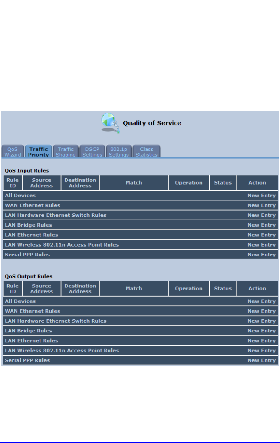
MP252 Multimedia Home Gateway 11. Quality of Service
Version 3.4.0 113 June 2011
Connection-based QoS also allows inheriting QoS parameters by some of the applications
that open subsequent connections. For instance, you can define QoS rules on SIP and the
rules then apply to both control and data ports (even if the data ports are unknown). This
feature applies to all applications that have ALG at firewall:
Any
User Defined (FTP, HTTP, HTTPS, TFTP, IMAP, PING, POP3, SNMP, SMTP, Telnet,
L2TP, Traceroute or any other protocol)
¾ To set traffic priority rules:
1. From the menu bar, click the QoS menu, and then select the Traffic Priority tab; the
'Traffic Priority' screen appears.
Figure 11-7: Traffic Priority Screen
This screen is divided into two identical groups - ’QoS Input Rules’ and ’QoS Output
Rules’ - for prioritizing inbound and outbound traffic respectively. Each group lists all the
devices on which rules can be set. You can set rules on all devices at once by clicking
the New Entry link corresponding to 'All Devices'
2. After clicking the appropriate New Entry link, the 'Add Traffic Priority Rule' screen
appears.
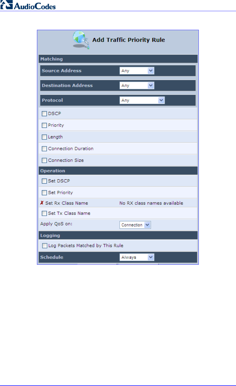
MP252 Multimedia Home Gateway 114 Document #: LTRT-23504
User's Manual
Figure 11-8: Add Traffic Priority Rule Screen
3. Under the Matching group, configure the matching characteristics:
a. From the ‘Source Address’ drop-down list, select 'Any', 'User Defined' or the host
as the source address of the packets sent to or received from the network object. If
you have created network objects (see Section 4.5.2 on page 46), then these are
also displayed in the list (or you can create one by selecting ‘User Defined’).
b. From the ‘Destination Address’ drop-down list, select the network object for the
destination address of the packets sent to or received from the network object. See
Step 3 above for a detailed explanation on the options.
c. From the ‘Protocol’ drop-down list, select the protocol. You can apply the rule to all
protocols (i.e., ‘Any’) or select an already defined protocol. You can create a new
protocol by selecting ‘User Defined’, and then following the procedure described in
Section 4.5.3 on page 47.
d. To match DSCP, select the ‘DSCP’ check box, and then enter the DSCP markings.
e. To match priority, select the ‘Priority’ check box, and then select the priority of the
packets.

MP252 Multimedia Home Gateway 11. Quality of Service
Version 3.4.0 115 June 2011
f. To match the Device, select the ‘Device’ check box, and then select the Device
interface.
g. To match packet or data length, select the ‘Length’ check box, and then enter the
data or packet length.
h. To match connection duration, select the ‘Connection Duration’ check box, and
then enter the duration of the connection (greater or less than).
i. To match connection size, select the ‘Connection Size’ check box, and then enter
the connection size.
4. Under the Operation group, configure the QoS operation:
a. Select the ‘Set DSCP’ check box to mark a DSCP value on packets matching this
rule and then enter the hexadecimal value of the DSCP.
b. Select the ‘Set Priority’ check box to add a priority to the rule and then select the
priority level (where 0 is the lowest and 7 the highest). This sets the priority of a
packet on the connection matching the rule, while routing the packet.
c. Select the ‘Tx Class Name’ check box, and then select the class name that you
defined.
d. From the ‘Apply QoS on’ drop-down list, select whether you want to apply the QoS
rule on the connection or on the packet.
5. Select the ‘Log Packets Matched by This Rule’ check box to log the first packet from a
connection that matches by this rule.
6. From the ‘Schedule’ drop-down list, select the time segments during which the rule may
be active. By default, the rule is always active (i.e., ‘Always’). If you have defined
Scheduler rules (see Section 4.5.1 on page 43), then these are also displayed as
options. To define a new one Scheduler rule, select ‘User Defined’.
7. Click OK to save the settings.
11.4 DSCP Mapping
To understand Differentiated Services Code Point (DSCP), one must first be familiarized with
the Differentiated Services (DiffServ) model. DiffServ is a Class of Service (CoS) model that
enhances best-effort Internet services by differentiating traffic by users, service requirements
and other criteria. Packets are specifically marked, allowing network nodes to provide
different levels of service, as appropriate for voice calls, video playback or other
delay-sensitive applications, via priority queuing or bandwidth allocation, or by choosing
dedicated routes for specific traffic flows.
DiffServ defines a field in IP packet headers referred to as DSCP. Hosts or routers passing
traffic to a DiffServ-enabled network typically mark each transmitted packet with an
appropriate DSCP. The DSCP markings are used by DiffServ network routers to
appropriately classify packets and to apply particular queue handling or scheduling behavior.
MP252 provides a table of predefined DSCP values, which are mapped to 802.1p priority
marking method. You can edit or delete any of the existing DSCP setting, as well as add new
entries.
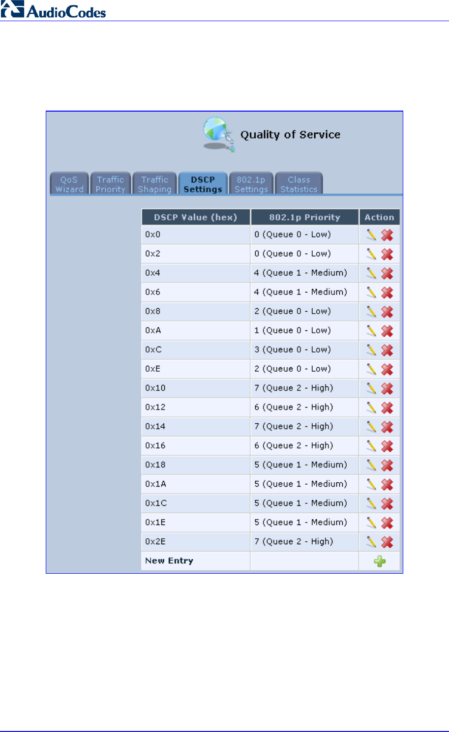
MP252 Multimedia Home Gateway 116 Document #: LTRT-23504
User's Manual
¾ To view and set DSCP rules:
1. From the menu bar, click the QoS menu link, and then click the DSCP Settings tab; the
following screen appears:
Figure 11-9: DSCP Settings Screen
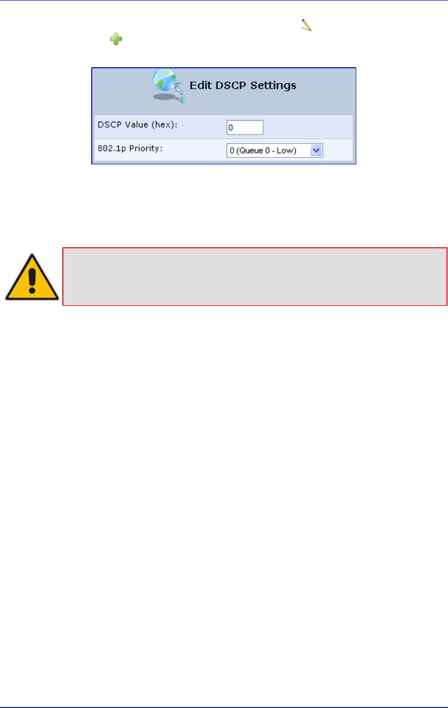
MP252 Multimedia Home Gateway 11. Quality of Service
Version 3.4.0 117 June 2011
2. To edit an existing entry, click its corresponding Edit icon. To add a new entry, click
the New icon. In both cases, the ’Edit DSCP Settings’ screen appears:
Figure 11-10: Edit DSCP Settings
3. In the ‘DSCP Value (hex)’ field, enter a hexadecimal number for the DSCP value.
4. In the ‘802.1p Priority’ drop-down list, select an 802.1p priority level (each priority level
is mapped to low, medium, or high priority).
5. Click OK to save your settings.
Note: The DSCP value overriding the priority of incoming packets with an unassigned
value (priority 0, assumed to be a no-priority-set) is ‘0x0’. By default, this value is
mapped to 802.1p priority level ‘0 -Low’, which means that such packets receive
the lowest priority.
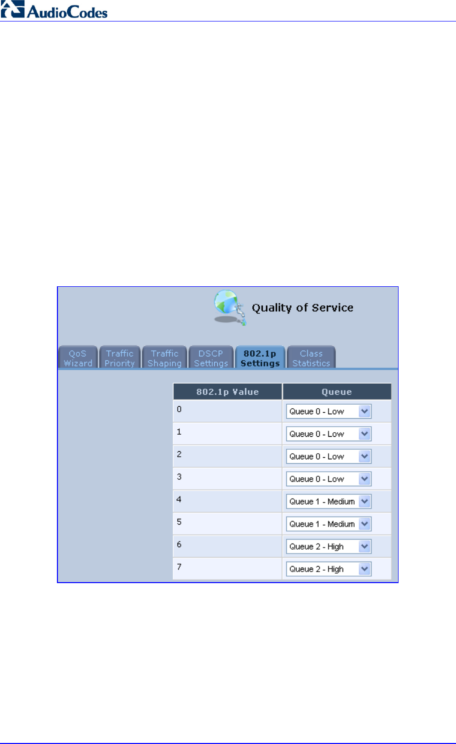
MP252 Multimedia Home Gateway 118 Document #: LTRT-23504
User's Manual
11.5 802.1p Mapping
The IEEE 802.1p priority marking method is a standard for prioritizing network traffic at the
data link/MAC sub-layer. 802.1p traffic is simply classified and sent to the destination, with no
bandwidth reservations established.
The 802.1p header includes a 3-bit prioritization field, which allows packets to be grouped
into eight levels of priority. MP252 maps these eight levels to three main priorities: high,
medium and low. By default, values six and seven are mapped to high priority, which may be
assigned to network-critical traffic. Values four and five are mapped to medium priority, which
may be applied to delay-sensitive applications, such as interactive video and voice. Values
three to zero are mapped to low priority, which may range from controlled-load applications
down to ‘loss eligible’ traffic. The zero value is normally used for best-effort traffic. It is the
default value for traffic with unassigned priority.
¾ To set 802.1p rules:
1. From the menu bar, click the QoS menu link, and then click the 802.1p Settings tab; the
following screen appears:
Figure 11-11: 802.1p Settings Screen
2. The eight 802.1p values are pre-configured with the three priority levels: high, medium
and low. You can change these levels for each of the eight values in their respective
drop-down list.
3. Click OK to save the settings.
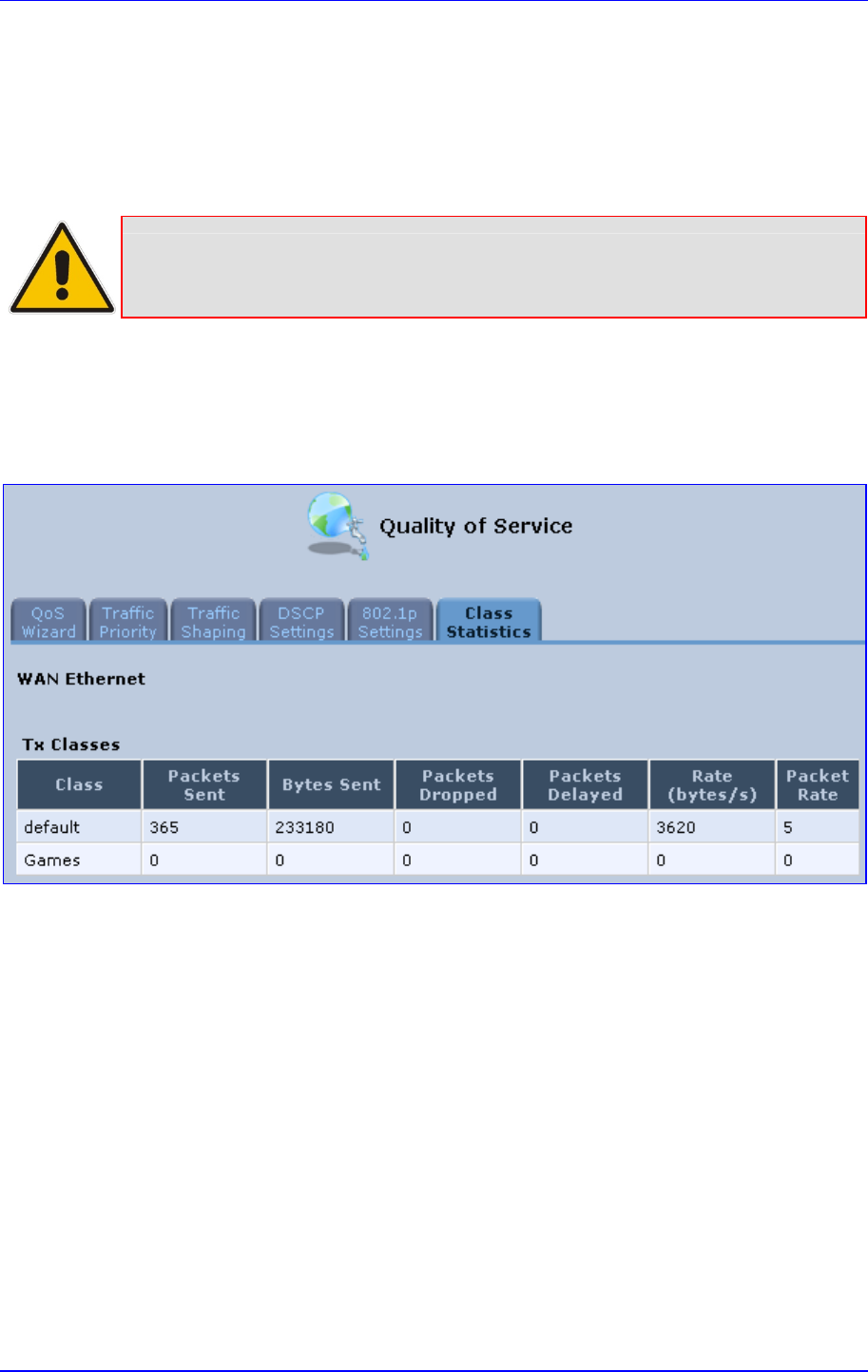
MP252 Multimedia Home Gateway 11. Quality of Service
Version 3.4.0 119 June 2011
11.6 Class Statistics
MP252 provides accurate, real-time information on the traffic passing through your defined
device classes. For example, the amount of packets sent, dropped, or delayed are just a few
of the parameters that you can monitor per each shaping class.
Note: Class statistics are available only if you have defined at least one class
(otherwise no information is displayed).
¾ To view your class statistics:
From the menu bar, click the QoS menu link, and then click the Class Statistics tab;
the following screen appears:
Figure 11-12: Class Statistics Screen

MP252 Multimedia Home Gateway 120 Document #: LTRT-23504
User's Manual
11.7 Configuring Basic VoIP QoS
The 'Traffic Shaping' feature only ensures priority to calls that originate from inside MP252.
When giving VoIP priority over data, the bottleneck is effectively moved from the Cable /
ADSL modem into MP252. To give priority to calls from the LAN, you must define a traffic
priority rule (for SIP and RTP from the device on the LAN).
This section recommends a minimal QoS configuration that ensures sufficient QoS for VoIP
calls when MP252 is connected behind a broadband (cable or DSL) modem with limited
uplink bandwidth and the user runs bandwidth-consuming applications on the PC.
Since most modems do not have any priority mechanisms, the Tx bandwidth of MP252
should be limited according to the modem’s uplink bandwidth. Since MP252 automatically
gives higher priority to VoIP packets (in its internal queues), it is not necessary to define
traffic shaping classes.
¾ To configure basic QoS for VoIP:
1. From the menu bar, click the QoS menu link, and then click the Traffic Shaping tab; the
‘Traffic Shaping’ screen appears.
2. Click the New icon; the screen 'Add Device Traffic Shaping' appears.
3. From the 'Device' drop-down list, select 'Default WAN Device' (or your PPTP/L2TP
connection you have created), and then click OK; the 'Edit Device Traffic Shaping'
screen appears.
4. Limit the Tx bandwidth (in the 'Tx Bandwidth' field) according to your modem’s uplink
bandwidth.
5. To prevent jitter in outgoing RTP packets, from the 'TCP Serialization' drop-down list,
select 'Enabled', and then in the 'Maximum Delay' field, define the maximum allowed
delay (e.g. 20 milliseconds). This causes long TCP packets to be fragmented when
there is an active voice call.
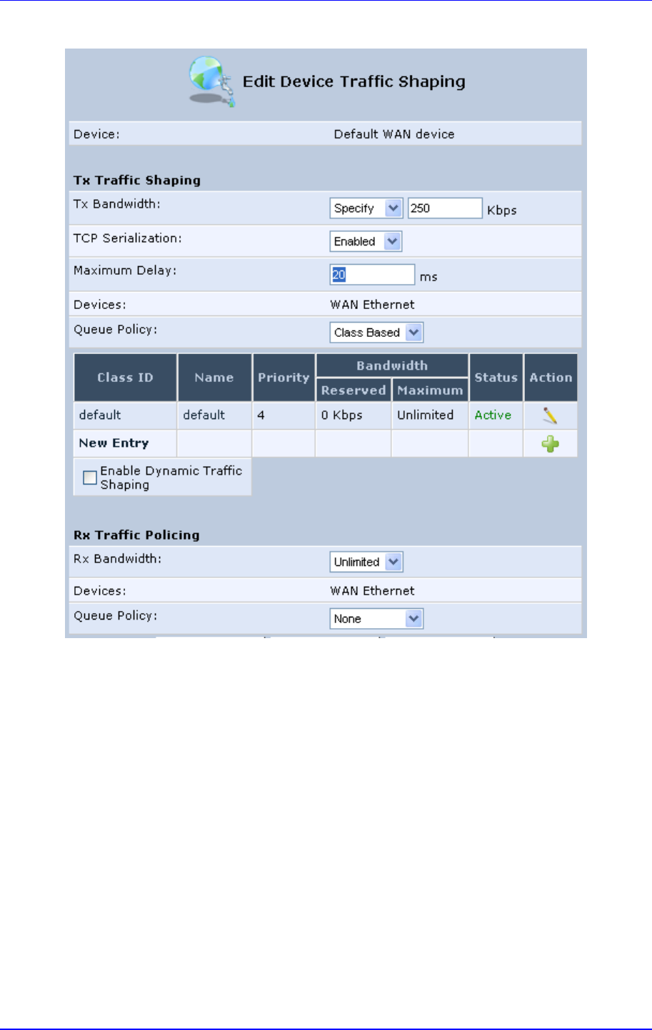
MP252 Multimedia Home Gateway 11. Quality of Service
Version 3.4.0 121 June 2011
Figure 11-13: Edit Device Traffic Shaping
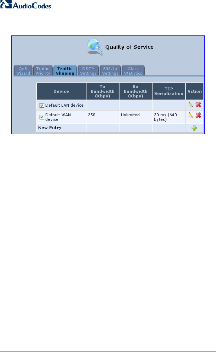
MP252 Multimedia Home Gateway 122 Document #: LTRT-23504
User's Manual
6. Click OK to apply the new definition.
Figure 11-14: QoS - Edit Device Traffic Shaping - Submitting the Configuration
7. Click OK again.

Version 3.4.0 123 July 2011
MP252 Multimedia Home Gateway 12. Network Connections
12 Network Connections
This chapter provides a detailed description on how to configure the following network
connections:
WAN – see Section 12.1 on page 123
LAN – see Section 12.2 on page 143
VLANs – see Section 12.4 on page 173
LAN-WAN Bridging – see Section 12.5 on page 180
12.1 Configuring a WAN Connection
This section describes how to configure your WAN Internet (WAN Ethernet or WAN DSL)
connection.
The WAN connection is configured in the ‘Network Connections’ screen, which provides a
connection wizard that guides you through the network configuration stages.
Notes:
• To quickly configure a basic WAN connection, use the ‘Quick Setup’
screen, as described in Section 7.1 on page 57.
• Before configuring the MP252 Internet connection, ensure that you have
obtained relevant technical information on the Internet connection type from
your Internet Telephony Service Provider (ITSP). For example, whether you
are connected to the Internet using a static or dynamic IP address, or what
protocols such as PPTP or PPPoE are used to communicate over the
Internet.
• MP252 automatically detects the physical WAN type (i.e., Ethernet or
ADSL). To change the WAN type, you must restore MP252 to factory
settings (see Section 18.8).
• When connected to ADSL, the LAN4/WAN Ethernet port can be used for
Ethernet LAN interface.
• When connected to an external modem through the Ethernet LAN4/WAN
port and MP252 obtains an IP address, the ADSL interface is disabled.
• If the Automatic Dialer feature is shipped preconfigured (i.e., enabled), then
MP252 automatically detects the Internet dialer type and therefore, Internet
connection configuration is unnecessary. However, it is recommended to
manually configure the Internet connection after the Automatic Dialer
process has completed (successfully or not). For more information on the
Automatic Dialer feature, see Section 7.2 on page 66.
¾ To start the Connection Wizard:
1. From the menu bar, click the Network Connections menu; the 'Network Connections'
screen appears.
Figure 12-1: Network Connections Screen
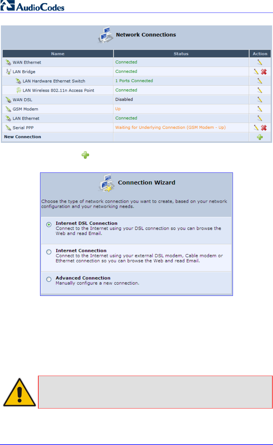
MP252 Multimedia Home Gateway 124 Document #: LTRT-23504
User's Manual
1. Click the New icon; the ‘Connection Wizard’ screen appears:
Figure 12-2: Connection Wizard Screen
2. Select the required network connection group:
• Internet DSL Connection: configures an Internet connection when using the
MP252 integrated DSL modem (see Section 12.1.1 on page 125)
• Internet Connection: configures an Internet connection when using an external
DSL modem, Cable modem or Ethernet connection modem (see Section 12.1.2 on
page 135)
• Advanced Connection: configures the WAN connection types as well as network
bridging and VLANs
Notes:
• For configuring VLANS, see Section 12.4 on page 173.
• For configuring network bridging, see Section 12.5 on page 180.
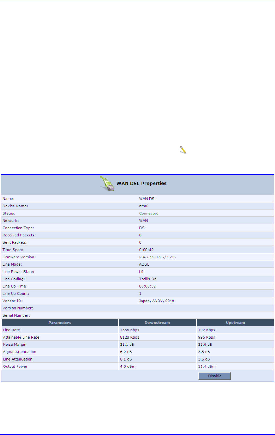
MP252 Multimedia Home Gateway 12. Network Connections
Version 3.4.0 125 June 2011
12.1.1 WAN DSL Connections
You can configure the following WAN DSL connection types:
Determine Protocol Type Automatically (PVC scan) – see Section 12.1.1.1 on page 125
Point-to-Point Protocol over Ethernet (PPPoE) – see Section 12.1.1.2 on page 126
Point-to-Point Protocol over ATM (PPPoA) – see Section 12.1.1.3 on page 128
Routed Ethernet Connection over ATM (Routed ETHoA) – see Section 12.1.1.4 on
page 130
LAN-WAN Bridged Ethernet Connection over ATM (Bridged ETHoA) – see Section
12.1.1.4 on page 130
Classical IP over ATM (CLIP) – see Section 12.1.1.5 on page 132
Routed IP over ATM (IPoA) – see Section 12.1.1.6 on page 134
If you have established a WAN DSL connection, you can view the properties of this
connection as described below.
¾ To view the WAN DSL properties:
In the ‘Network Connections’ screen, click the Edit icon corresponding to the WAN
DSL network connection; the ‘WAN DSL Properties’ screen appears:
Figure 12-3: WAN DSL Properties Screen
12.1.1.1 Determine Protocol Type Automatically (PVC Scan)
The Determine Protocol Type Automatically (PVC Scan) connection type automatically
scans for a VPI/VCI pair, necessary when connecting to DSL. If such a pair is not found, your
service provider should supply you with one.
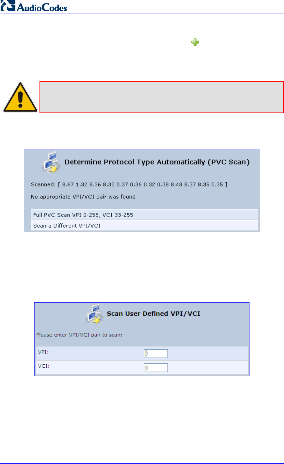
MP252 Multimedia Home Gateway 126 Document #: LTRT-23504
User's Manual
¾ To automatically scan for a VPI / VCI pair:
1. In the 'Network Connections' screen, click the New icon; the 'Connection Wizard'
screen appears.
2. Select the Internet DSL Connection option, and then click Next; the 'Internet DSL
Connection' screen appears.
Note: You can also create a PVC connection using the Advanced Connection
option.
3. Select the Determine Protocol Type Automatically (PVC Scan) option, and then click
Next; the scan begins, refreshing the screen every few seconds to display the progress.
Figure 12-4: Determine Protocol Type Automatically (PVC Scan) Screen
You can click the following links:
Full PVC Scan VPI 0-255, VCI 33-255: initiates a longer, more thorough scan, between
VPI 0-255 and VCI 33-255.
Scan a Different VPI/VCI: scans for specific VPI/VCI pair. The 'Scan User Defined
VPI/VCI' screen appears (as shown below). Enter the VPI/VCI pair you wish to scan and
then click OK.
Figure 12-5: Scan User Defined VPI/VCI Screen
12.1.1.2 PPPoE
PPPoE relies on two widely accepted standards, PPP and Ethernet. PPPoE enables your
home network PCs that communicate on an Ethernet System network to exchange
information with PCs on the Internet. PPPoE supports the protocol layers and authentication
widely used in PPP and enables a point-to-point connection to be established in the normally
multipoint architecture of Ethernet. A discovery process in PPPoE determines the Ethernet
MAC address of the remote device to establish a session.
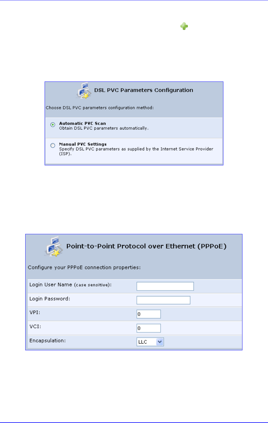
MP252 Multimedia Home Gateway 12. Network Connections
Version 3.4.0 127 June 2011
¾ To create a PPPoE connection:
1. In the 'Network Connections' screen, click the New icon; the 'Connection Wizard'
screen appears.
2. Select the Internet DSL Connection option, and then click Next; the 'Internet DSL
Connection' screen appears.
3. Select the Point-to-Point Protocol over Ethernet (PPPoE) option, and then click
Next; the 'DSL PVC Parameters Configuration' screen appears.
Figure 12-6: DSL PVC Parameters Configuration Screen
4. Select one of the following options:
• Automatic PVC Scan: If you want to obtain the DSL PVC parameters
automatically
• Manual PVC Settings: If you do not want to obtain the DSL PVC parameters
automatically
5. Click Next; the 'Point-to-Point Protocol over Ethernet (PPPoE)' screen appears.
Figure 12-7: Point-to-Point Protocol over Ethernet (PPPoE) Screen
6. Enter your PPPoE login username and password (provided by your ITSP).
7. If you selected the Manual PVC Settings option in the previous step, you also need to
configure the following:
• VPI and VCI pair of identifiers.
• Encapsulation method - LLC, VCMux, or VCMux HDLC.
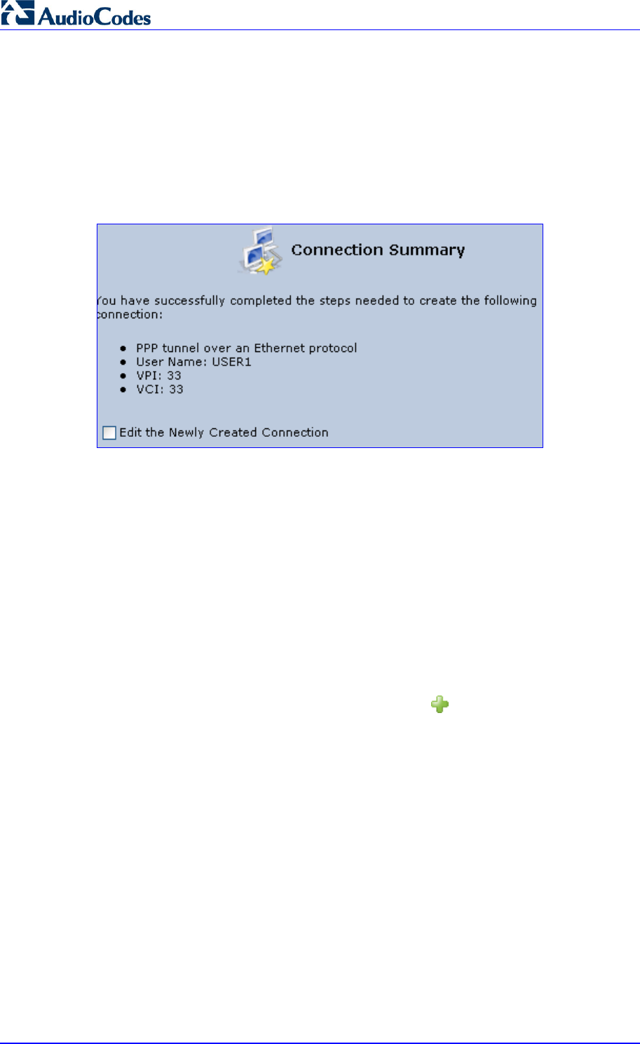
MP252 Multimedia Home Gateway 128 Document #: LTRT-23504
User's Manual
Asynchronous Transfer Mode (ATM) is a network technology based on transferring data
in cells or packets of a fixed size. The cell used with ATM is relatively small compared to
units used with other technologies. The small, constant cell size allows the transmission
of video, audio, and computer data, assuring that no single type of data consumes the
connection. ATM addressing consists of two identifiers that identify the virtual path (VPI)
and the virtual connection (VCI). A virtual path consists of multiple virtual channels to
the same endpoint.
8. Click Next; the 'Connection Summary' screen appears:
Figure 12-8: Connection Summary Screen
9. Select the 'Edit the Newly Created Connection' check box if you want to perform
additional configurations after clicking Finish.
10. Click Finish to save the settings; the new PPPoE connection is added to the ‘Network
Connections’ screen.
12.1.1.3 PPPoA
PPPoA is a standard for incorporating the popular PPP protocol into a DSL connection that
uses ATM as its networking protocol. From the PC, IP packets travel over an Ethernet
connection to the MP252, which encapsulates the PPP protocol to the IP packets and
transports them to the service provider's DSLAM over ATM.
¾ To create a PPPoA connection:
1. In the 'Network Connections' screen, click the New icon; the 'Connection Wizard'
screen appears.
2. Select the Internet DSL Connection option, and then click Next; the 'Internet DSL
Connection' screen appears.
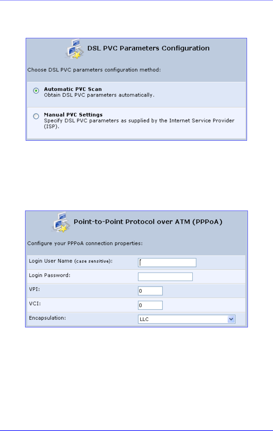
MP252 Multimedia Home Gateway 12. Network Connections
Version 3.4.0 129 June 2011
3. Select the Point-to-Point Protocol over ATM (PPPoA) option, and then click Next; the
'DSL PVC Parameters Configuration' screen appears.
Figure 12-9: DSL PVC Parameters Configuration Screen
4. Select one of the following options:
• Automatic PVC Scan: If you want to obtain the DSL PVC parameters
automatically
• Manual PVC Settings: If you do not want to obtain the DSL PVC parameters
automatically
5. Click Next; the 'Point-to-Point Protocol over ATM (PPPoA)' screen appears.
Figure 12-10: Point-to-Point Protocol over ATM (PPPoA) Screen
6. Enter your PPPoA login username and password (provided by your ITSP).
7. If you selected the Manual PVC Settings option in the previous step, you also need to
configure the following:
• VPI and VCI pair of identifiers.
• Encapsulation method - LLC, VCMux, or VCMux HDLC.
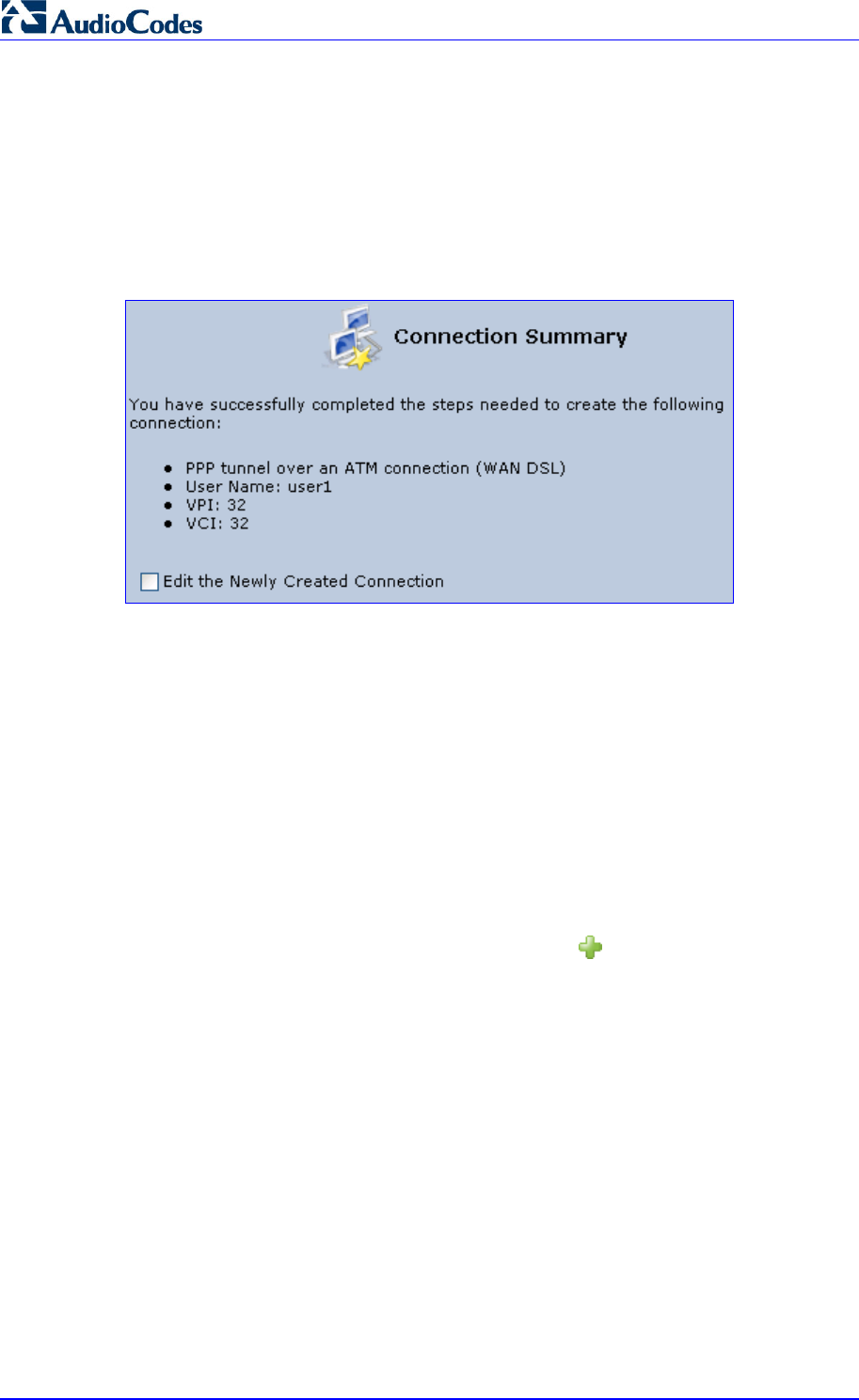
MP252 Multimedia Home Gateway 130 Document #: LTRT-23504
User's Manual
Asynchronous Transfer Mode (ATM) is a network technology based on transferring data
in cells or packets of a fixed size. The cell used with ATM is relatively small compared to
units used with other technologies. The small, constant cell size allows the transmission
of video, audio, and computer data, assuring that no single type of data consumes the
connection. ATM addressing consists of two identifiers that identify the virtual path (VPI)
and the virtual connection (VCI). A virtual path consists of multiple virtual channels to
the same endpoint.
8. Click Next; the 'Connection Summary' screen appears:
Figure 12-11: Connection Summary Screen
9. Select the 'Edit the Newly Created Connection' check box if you want to perform
additional configurations after clicking Finish.
10. Click Finish to save the settings; the new PPPoA connection is added to the ‘Network
Connections’ screen.
12.1.1.4 Routed ETHoA or Bridged ETHoA
The Ethernet over ATM (ETHoA) connection allows transport of Ethernet frames on DSL
connections. When creating an ETHoA connection, it is bridged to the LAN. You must
configure a dialup connection on the LAN computer with your ITSP’s user name and
password.
¾ To create an ETHoA connection:
1. In the 'Network Connections' screen, click the New icon; the 'Connection Wizard'
screen appears.
2. Select the Internet DSL Connection option, and then click Next; the 'Internet DSL
Connection' screen appears.
3. Select one of the following options:
• Routed Ethernet Connection over ATM (Routed ETHoA):
a. Click Next; the 'DSL PVC Parameters Configuration' screen appears.
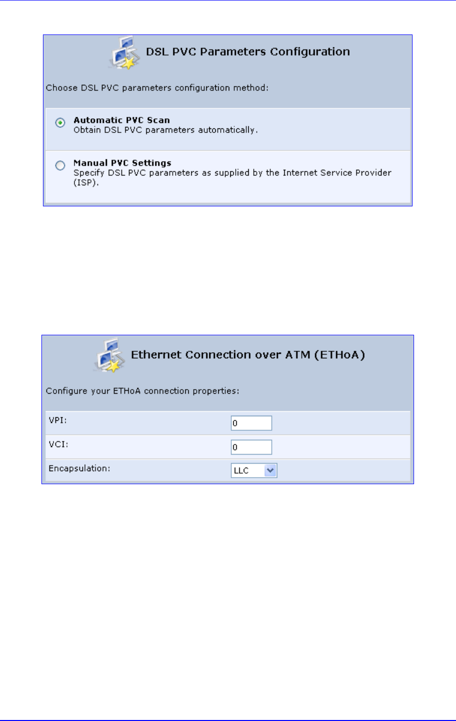
MP252 Multimedia Home Gateway 12. Network Connections
Version 3.4.0 131 June 2011
Figure 12-12: DSL PVC Parameters Configuration Screen
b. Select one of the following options:
9 Automatic PVC Scan: If you want to obtain the DSL PVC parameters
automatically
9 Manual PVC Settings: If you do not want to obtain the DSL PVC
parameters automatically
• LAN-WAN Bridged Ethernet Connection over ATM (Bridged ETHoA):
a. Click Next; the ‘Ethernet Connection over ATM (ETHoA)' screen appears.
Figure 12-13: Ethernet Connection over ATM (ETHoA) Screen
4. If you selected the Manual PVC Settings option, you also need to configure the
following:
• VPI and VCI pair of identifiers.
• Encapsulation method - LLC, VCMux, or VCMux HDLC.
Asynchronous Transfer Mode (ATM) is a network technology based on transferring data
in cells or packets of a fixed size. The cell used with ATM is relatively small compared to
units used with other technologies. The small, constant cell size allows the transmission
of video, audio, and computer data, assuring that no single type of data consumes the
connection. ATM addressing consists of two identifiers that identify the virtual path (VPI)
and the virtual connection (VCI). A virtual path consists of multiple virtual channels to
the same endpoint..
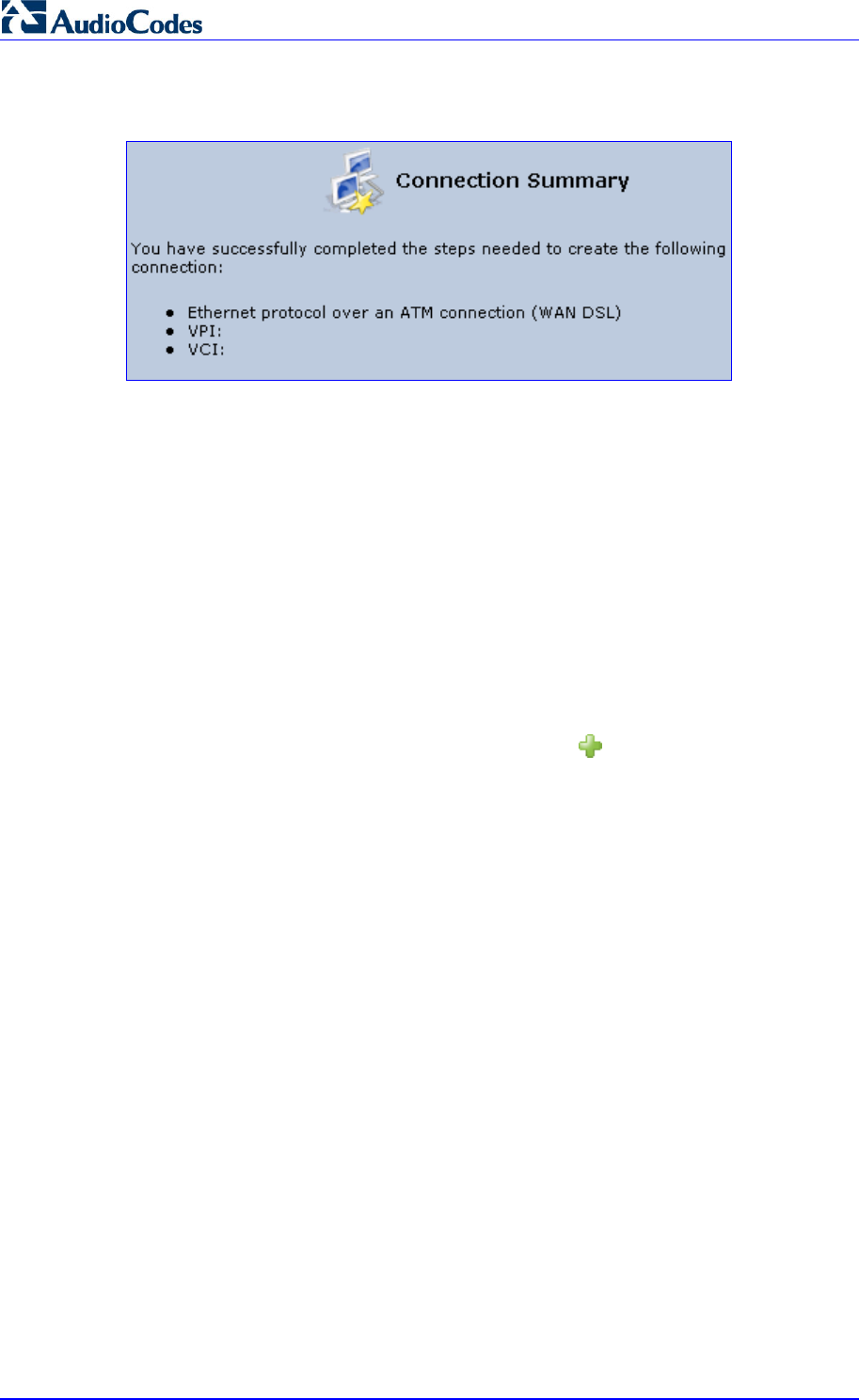
MP252 Multimedia Home Gateway 132 Document #: LTRT-23504
User's Manual
5. Click Next; the 'Connection Summary' screen appears:
Figure 12-14: Connection Summary Screen
6. Select the 'Edit the Newly Created Connection' check box if you want to perform
additional configurations after clicking Finish.
7. Click Finish to save the settings; the new ETHoA connection is added to the ‘Network
Connections’ screen.
12.1.1.5 CLIP
CLIP is a standard for transmitting IP traffic in an ATM network. IP protocols contain IP
addresses that have to be converted into ATM addresses, and Classical IP performs this
conversion, as long as the destination is within the same subnet. Classical IP does not
support routing between networks. The Classical IP-enabled driver in the end station sends
out an ARP request to a Classical IP-enabled ARP server, which returns the ATM address.
¾ To create a CLIP connection:
1. In the 'Network Connections' screen, click the New icon; the 'Connection Wizard'
screen appears.
2. Select the Internet DSL Connection option, and then click Next; the 'Internet DSL
Connection' screen appears.
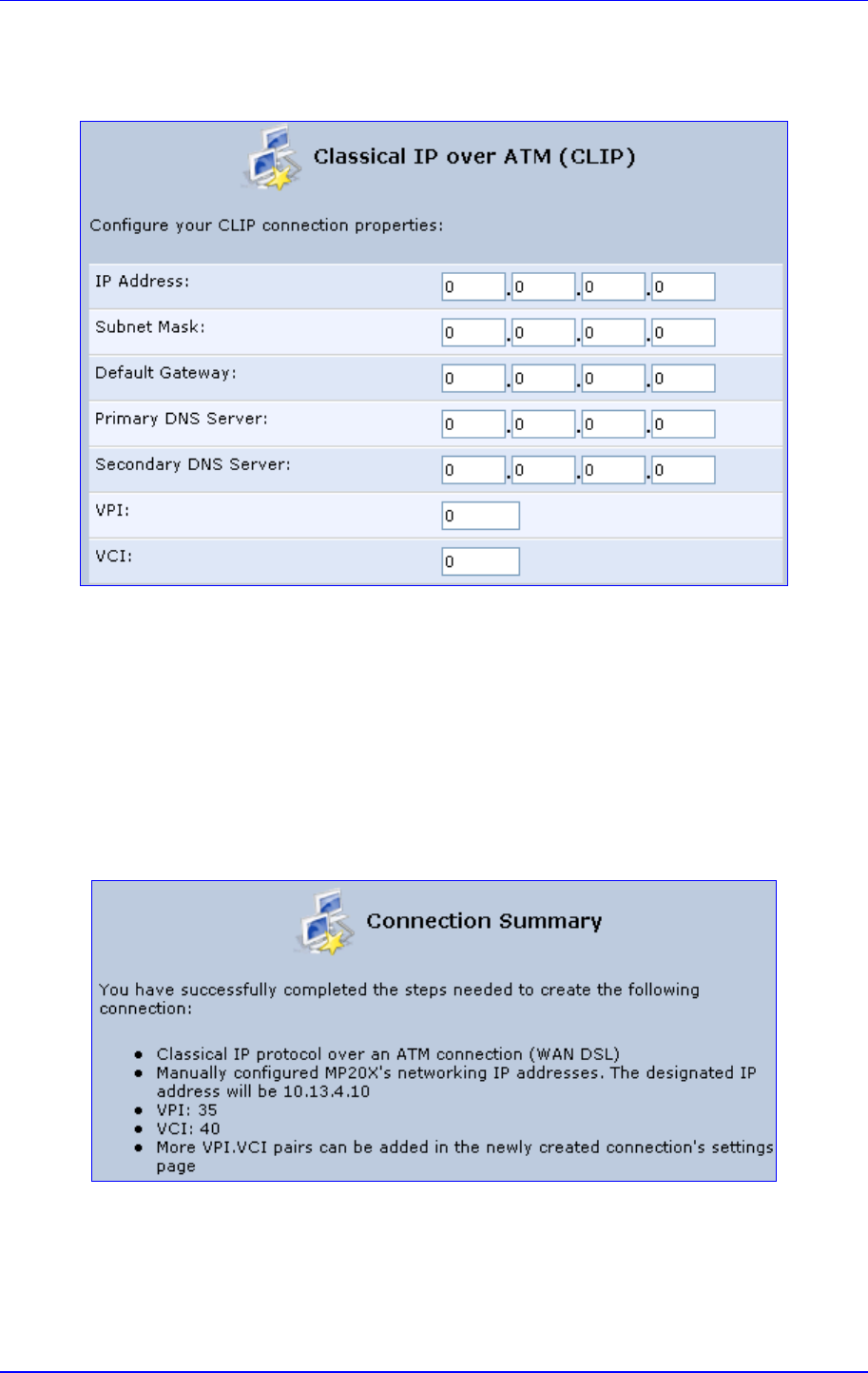
MP252 Multimedia Home Gateway 12. Network Connections
Version 3.4.0 133 June 2011
3. Select the Classical IP over ATM (CLIP) option, and then click Next; the ‘Classical IP
over ATM (CLIP)' screen appears.
Figure 12-15: Classical IP over ATM (CLIP) Screen
4. Enter the following information (provided by your ITSP):
• IP Address
• Subnet Mask
• Default Gateway
• Primary DNS Server
• Secondary DNS Server
• VPI and VCI pair of identifiers
5. Click Next; the 'Connection Summary' screen appears.
Figure 12-16: Connection Summary Screen
6. Select the 'Edit the Newly Created Connection' check box if you want to perform
additional configurations after clicking Finish.
7. Click Finish to save the settings; the new CLIP connection is added to the ‘Network
Connections’ list.
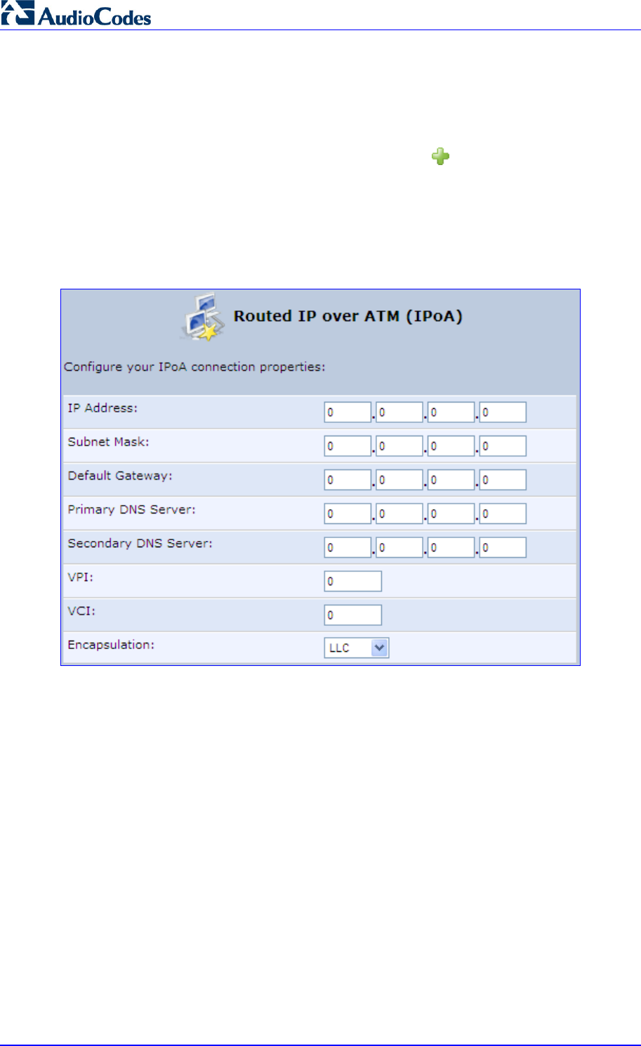
MP252 Multimedia Home Gateway 134 Document #: LTRT-23504
User's Manual
12.1.1.6 IPoA
Routed IP over ATM (IPoA) is a standard for transmitting IP traffic in an ATM network.
¾ To create an IPoA connection:
1. In the 'Network Connections' screen, click the New icon; the 'Connection Wizard'
screen appears.
2. Select the Advanced Connection option, and then click Next; the ‘Advanced
Connection' screen appears.
3. Select the Routed IP over ATM (IPoA) option, and then click Next; the ‘Routed IP over
ATM (IPoA)’ screen appears.
Figure 12-17: Routed IP over ATM (IPoA) Screen
4. Enter the IP address and networking parameters.
5. Enter the following parameters:
• VPI and VCI pair of identifiers.
• Encapsulation method: LLC, VCMux, or VCMux HDLC.
ATM is a network technology based on transferring data in cells or packets of a fixed
size. The cell used with ATM is relatively small compared to units used with other
technologies. The small, constant cell size allows the transmission of video, audio, and
computer data, assuring that no single type of data consumes the connection. ATM
addressing consists of two identifiers that identify the virtual path (VPI) and the virtual
connection (VCI). A virtual path consists of multiple virtual channels to the same
endpoint.
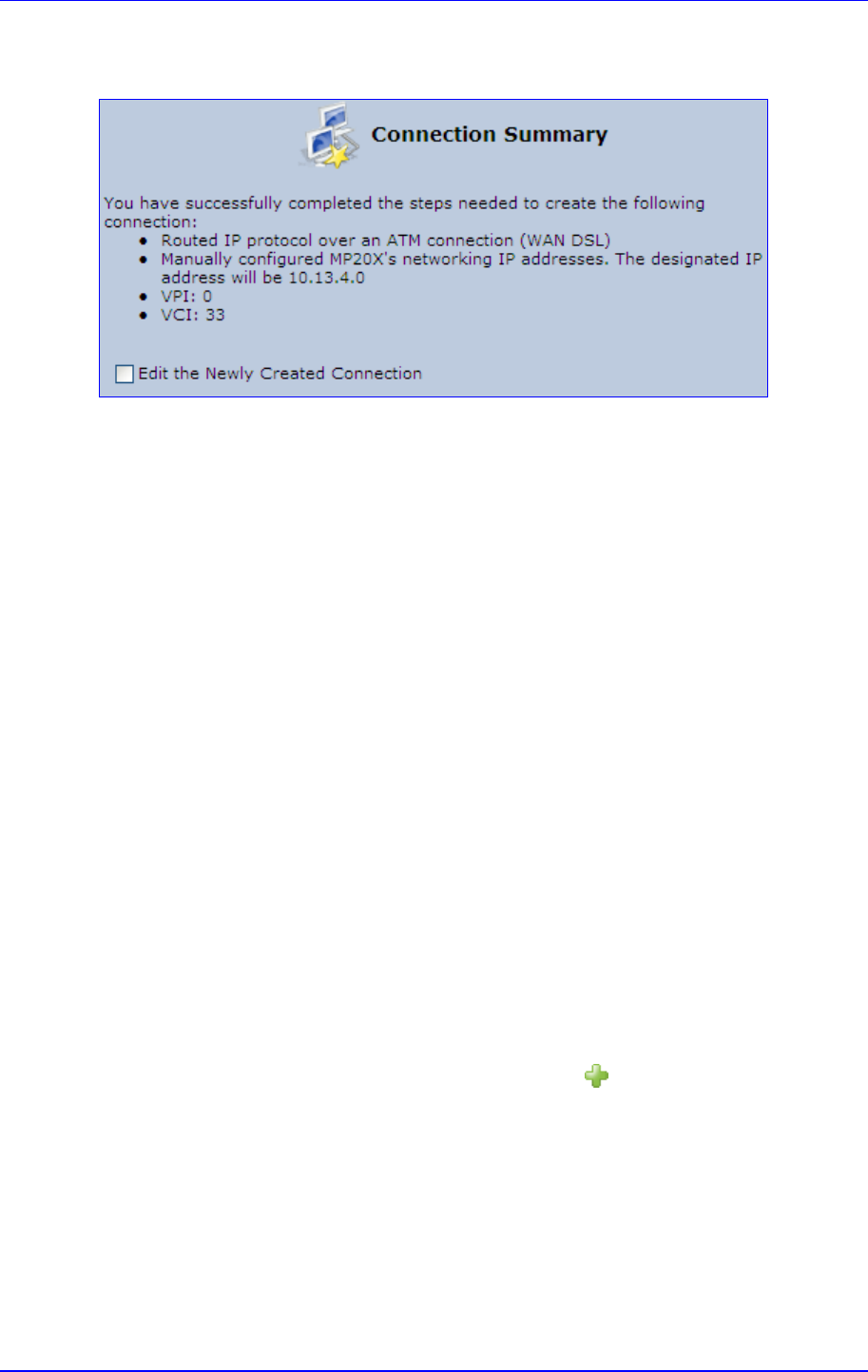
MP252 Multimedia Home Gateway 12. Network Connections
Version 3.4.0 135 June 2011
6. Click Next; the 'Connection Summary' screen appears:
Figure 12-18: Connection Summary Screen
7. Select the 'Edit the Newly Created Connection' check box if you want to perform
additional configurations after clicking Finish.
8. Click Finish to save the settings; the new connection is added to the ‘Network
Connections’ screen.
12.1.2 WAN Ethernet Connections
You can configure the following WAN Ethernet connection types:
MP252 connected to an external DSL modem and using PPPoE – see Section 12.1.2.1
on page 135
MP252 connected to an external Cable modem without authentication – see Section
12.1.2.2 on page 136
MP252 connected to an external Cable modem using PPTP – see Section 12.1.2.3 on
page 137
MP252 connected to an external Cable modem using L2TP – see Section 12.1.2.4 on
page 139
Automatic IP address using DHCP – see Section 12.1.2.5 on page 141
Manual IP address – see Section 12.1.2.6 on page 142
12.1.2.1 External DSL Modem using PPPoE
The procedure below describes how to configure an Internet connection using PPPoE when
MP252 is connected to an external DSL modem.
¾ To create a PPPoE connection for external DSL modem:
1. In the 'Network Connections' screen, click the New icon; the 'Connection Wizard'
screen appears.
2. Select the Internet Connection option, and then click Next; the ‘Internet Connection’
screen appears.
3. Select the External DSL Modem option, and then click Next; the 'Point-To-Point
Protocol over Ethernet (PPPoE)' screen appears.
Figure 12-19: Point-to-Point Protocol over Ethernet (PPPoE) Screen
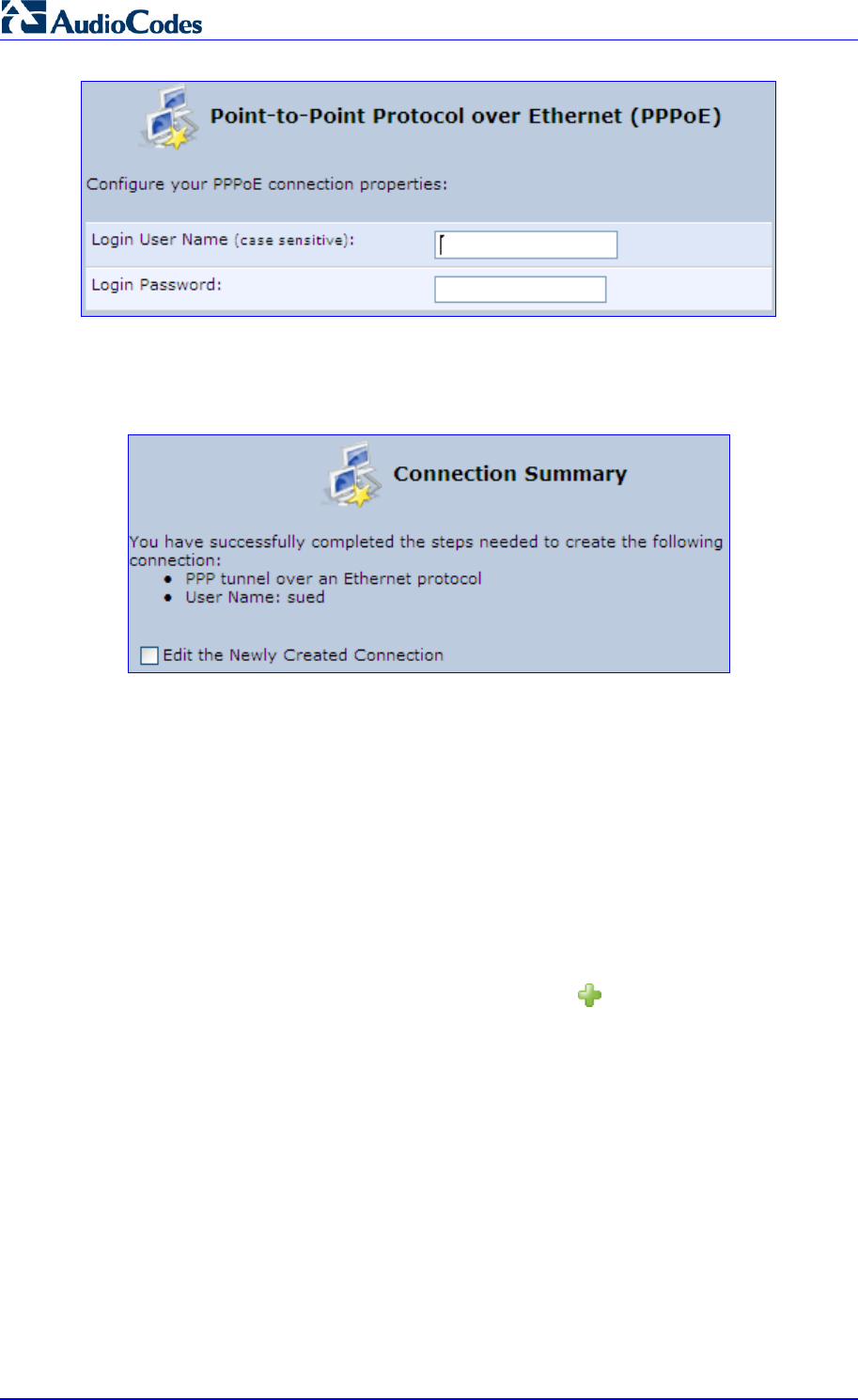
MP252 Multimedia Home Gateway 136 Document #: LTRT-23504
User's Manual
4. Enter the login PPPoE username and password.
5. Click Next; the screen 'Connection Summary' opens.
Figure 12-20: PPPoE Connection Summary
6. Select the 'Edit the Newly Created Connection' check box if you wish to be routed to the
new connection's configuration screen after clicking Finish.
7. Click Finish to save the settings; the new PPPoE connection is added to the ‘Network
Connections’ screen.
12.1.2.2 External Cable Modem without Authentication
The procedure below describes how to configure an Internet connection when MP252 is
connected to an external Cable modem and the ITSP does not require a username nor
password to connect.
¾ To create an Ethernet connection for external Cable modem:
1. In the 'Network Connections' screen, click the New icon; the 'Connection Wizard'
screen appears.
2. Select the Internet Connection option, and then click Next; the ‘Internet Connection’
screen appears.
3. Select the External Cable Modem option, and then click Next; the ‘Internet Cable
Modem Connection' screen appears.
Figure 12-21: Internet Cable Modem Connection Screen
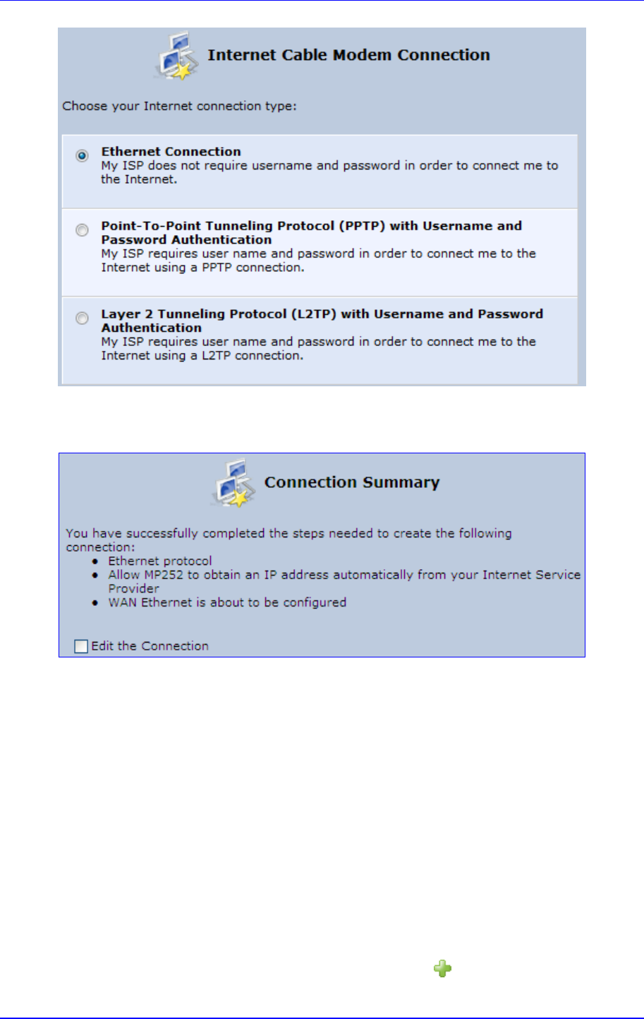
MP252 Multimedia Home Gateway 12. Network Connections
Version 3.4.0 137 June 2011
4. Select the Ethernet Connection option; the 'Connection Summary' screen appears.
Figure 12-22: Ethernet Connection Summary
5. Select the 'Edit the Connection' check box if you wish to be routed to the new
connection's configuration screen after clicking Finish.
6. Click Finish to save the settings; the new connection is added to the ‘Network
Connections’ screen.
12.1.2.3 External Cable Modem with PPTP
The procedure below describes how to configure an Internet connection when MP252 is
connected to an external Cable modem and using the PPTP protocol.
Point-to-Point Tunneling Protocol (PPTP) is a protocol developed by Microsoft targeted at
creating VPN connections over the Internet. This enables remote users to access MP252 via
any ISP that supports PPTP on its servers. PPTP encapsulates network traffic, encrypts
content using Microsoft's Point-to-Point Encryption (MPPE) protocol that is based on RC4,
and routes using the generic routing encapsulation (GRE) protocol.
¾ To create PPTP for external Cable modem:
1. In the 'Network Connections' screen, click the New icon; the 'Connection Wizard'
screen appears.
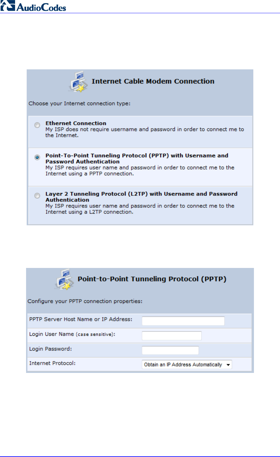
MP252 Multimedia Home Gateway 138 Document #: LTRT-23504
User's Manual
2. Select the Internet Connection option, and then click Next; the ‘Internet Connection’
screen appears.
3. Select the External Cable Modem option, and then click Next; the ‘Internet Cable
Modem Connection' screen appears.
Figure 12-23: Internet Cable Modem Connection Screen
4. Select the Point-To-Point Tunneling Protocol (PPTP) with Username and
Password Authentication option; the ‘Point-to-Point Tunneling Protocol (PPTP)'
screen appears.
Figure 12-24: Point-to-Point Tunneling Protocol (PPTP) Screen
5. Enter the PPTP server host name or IP address provided by your ITSP.
6. Enter the login user name and password provided by the administrator of the network
you are trying to access.
7. From the ‘Internet Protocol’ drop-down list, select whether the IP address is obtained
automatically or select ‘Use the Following IP Address’ and define the IP address.
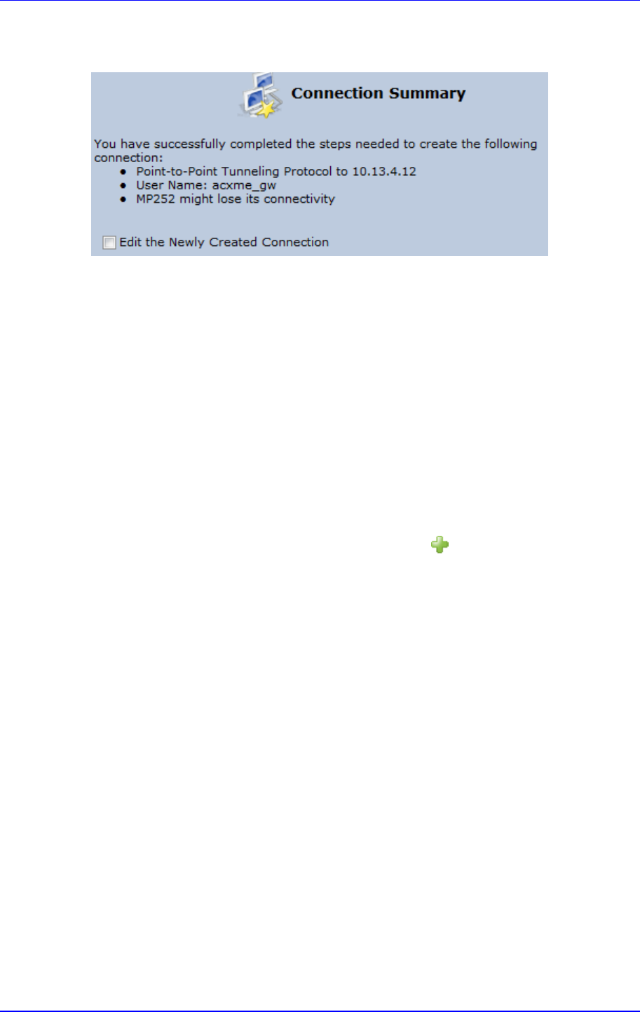
MP252 Multimedia Home Gateway 12. Network Connections
Version 3.4.0 139 June 2011
8. Click Next; the screen 'Connection Summary' opens.
Figure 12-25: PPTP Connection Summary
9. Select the 'Edit the Newly Created Connection' check box if you wish to be routed to the
new connection's configuration screen after clicking Finish.
10. Click Finish to save the settings; the new connection is added to the ‘Network
Connections’ screen.
12.1.2.4 External Cable Modem with L2TP
You can connect MP252 to the Internet using an external cable modem where the
connection is L2TP. L2TP is an extension to the PPP protocol, enabling MP252 to create
VPN connections. Derived from Microsoft's PPTP and Cisco's Layer 2 Forwarding (L2F)
technology, L2TP encapsulates PPP frames into IP packets either at the remote user's PC or
at an ISP that has an L2TP Remote Access Concentrator (LAC). The LAC transmits the
L2TP packets over the network to the L2TP Network Server (LNS) at the corporate side
¾ To create L2RP for external Cable modem:
1. In the 'Network Connections' screen, click the New icon; the 'Connection Wizard'
screen appears.
2. Select the Internet Connection option, and then click Next; the ‘Internet Connection’
screen appears.
3. Select the External Cable Modem option, and then click Next; the ‘Internet Cable
Modem Connection' screen appears.
Figure 12-26: Internet Cable Modem Connection Screen
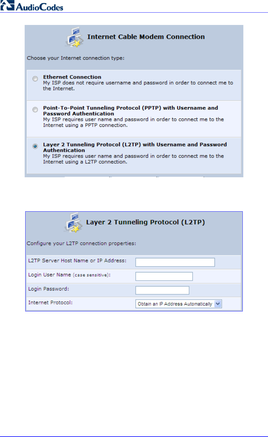
MP252 Multimedia Home Gateway 140 Document #: LTRT-23504
User's Manual
4. Select the Layer 2 Tunneling Protocol (L2TP) with Username and Password
Authentication option; the 'Layer 2 Tunneling Protocol (L2TP)' screen appears.
Figure 12-27: Layer 2 Tunneling Protocol (L2TP) Screen
5. Enter the L2TP server host name or IP address provided by your ITSP.
6. Enter the login user name and password provided by the administrator of the network
you are trying to access.
7. From the ‘Internet Protocol’ drop-down list, select whether the IP address is obtained
automatically or select ‘Use the Following IP Address’ and define the IP address.
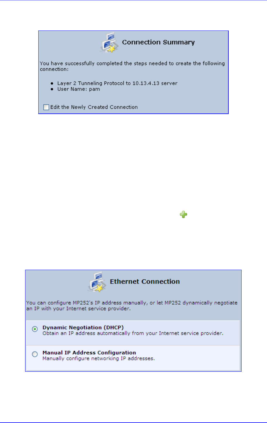
MP252 Multimedia Home Gateway 12. Network Connections
Version 3.4.0 141 June 2011
8. Click Next; the screen 'Connection Summary' opens.
Figure 12-28: L2TP Connection Summary
9. Select the 'Edit the Newly Created Connection' check box if you wish to be routed to the
new connection's configuration screen after clicking Finish.
10. Click Finish to save the settings; the new connection is added to the ‘Network
Connections’ screen.
12.1.2.5 DHCP
The Dynamic Host Configuration Protocol (DHCP) connection for the physical WAN
Ethernet, allows MP252 to obtain an IP address automatically from the service provider
when connecting to the Internet.
¾ To create a DHCP connection:
1. In the 'Network Connections' screen, click the New icon; the 'Connection Wizard'
screen appears.
2. Select the Internet Connection option, and then click Next; the ‘Internet Connection’
screen appears.
3. Select the Ethernet Connection option, and then click Next; the ‘Ethernet Connection'
screen appears.
Figure 12-29: Ethernet Connection Screen
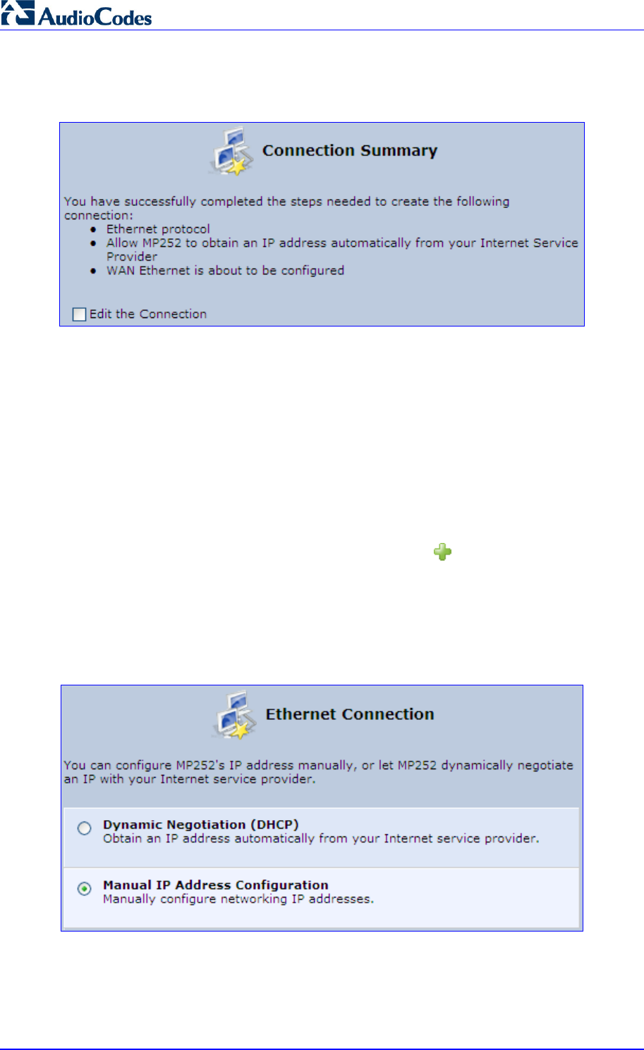
MP252 Multimedia Home Gateway 142 Document #: LTRT-23504
User's Manual
4. Select the Dynamic Negotiation (DHCP) option, and then click Next; the screen
'Connection Summary' opens.
Figure 12-30: DHCP Connection Summary
5. Select the 'Edit the Connection' check box if you wish to be routed to the new
connection's configuration screen after clicking Finish.
6. Click Finish to save the settings; the new connection is added to the ‘Network
Connections’ screen.
12.1.2.6 Manual IP Address
The Manual IP Address feature is used to manually configure the networking IP addresses
when connecting to the Internet.
¾ To manually configure the IP address:
1. In the 'Network Connections' screen, click the New icon; the 'Connection Wizard'
screen appears.
2. Select the Internet Connection option, and then click Next; the ‘Internet Connection’
screen appears.
3. Select the Ethernet Connection option, and then click Next; the ‘Ethernet Connection'
screen appears.
Figure 12-31: Ethernet Connection Screen
4. Select the Manual IP Address Configuration option, and then click Next; the screen
‘Manual IP Address Configuration’ opens.
Figure 12-32: Manual IP Address Configuration Screen
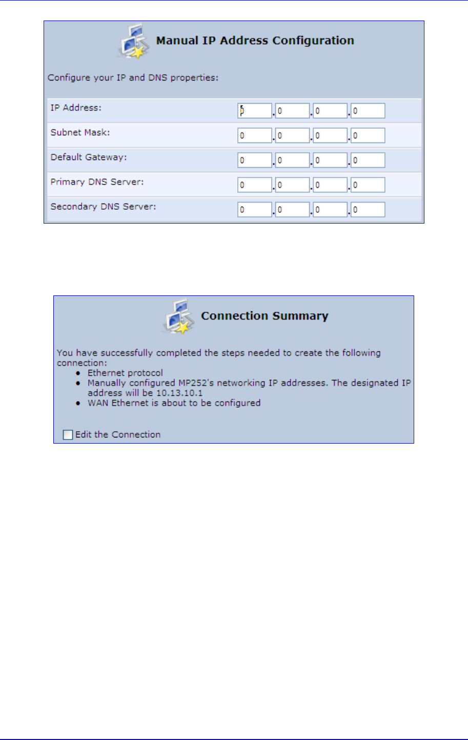
MP252 Multimedia Home Gateway 12. Network Connections
Version 3.4.0 143 June 2011
5. Configure the IP address and other network parameters, and then click Next; Select the
Manual IP Address Configuration option, and then click Next; the 'Connection
Summary' screen appears.
Figure 12-33: Manual IP Connection Summary
6. Select the 'Edit the Connection' check box if you wish to be routed to the new
connection's configuration screen after clicking Finish.
7. Click Finish to save the settings; the new connection is added to the ‘Network
Connections’ screen.
12.2 LAN Connection
This section describes how to configure the following MP252 LAN connections:
Wireless LAN
LAN hardware Ethernet switch
12.2.1 Wireless LAN
This section describes how to configure the MP252 wireless network. This network is
configured in the ‘Network Connections’ screen, which provides a connection wizard that
guides you through the network configuration stages.
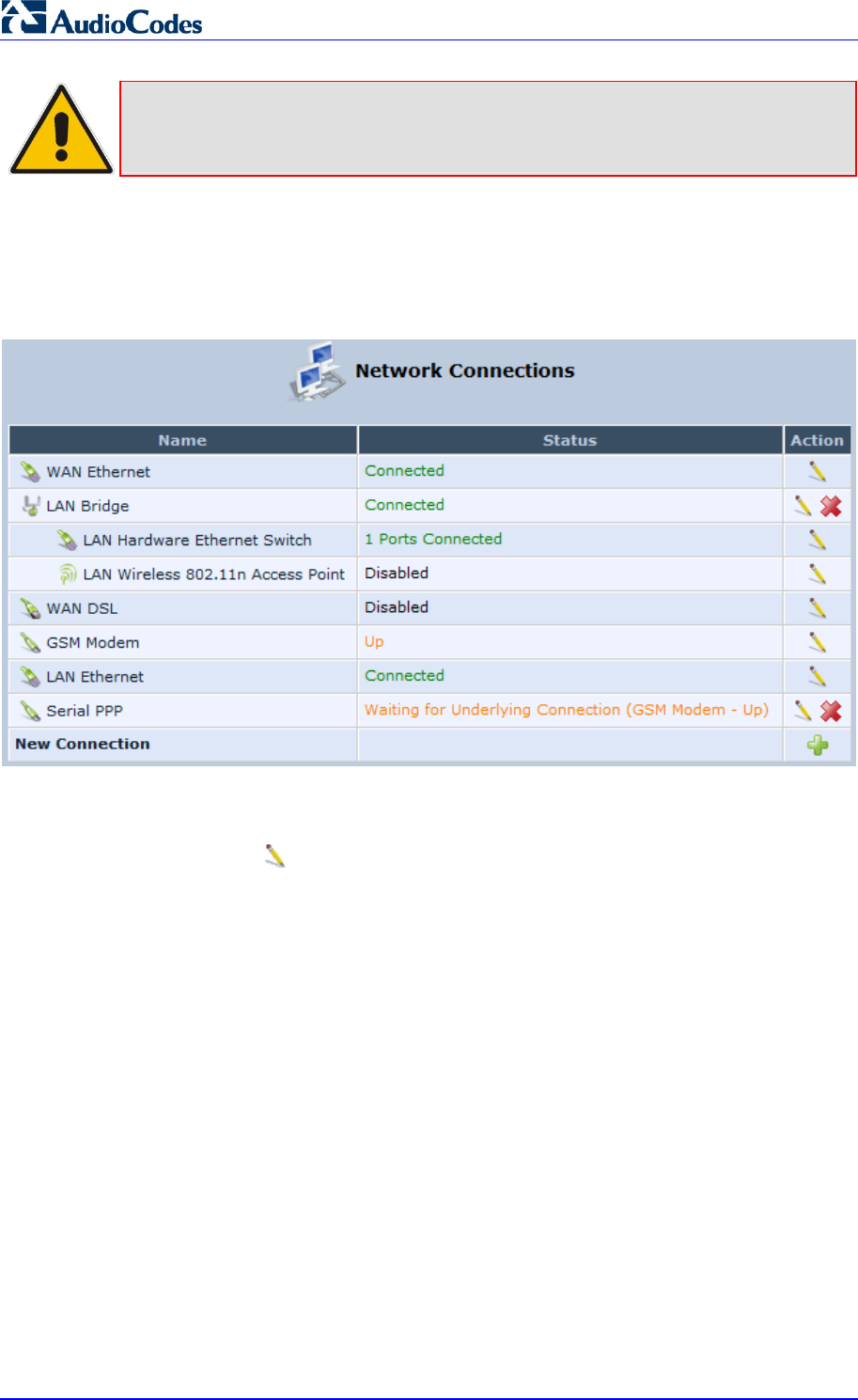
MP252 Multimedia Home Gateway 144 Document #: LTRT-23504
User's Manual
Note: To establish a wireless network connection between a PC and the MP252, you
must also configure the PC for wireless connectivity (see Section 6.2 on page
56).
¾ To configure the Wireless LAN:
1. From the menu bar, click the Network Connections menu; the 'Network Connections'
screen appears.
Figure 12-34: Network Connections Screen Displaying LAN Wireless Interface
The 'Status' column corresponding to the wireless LAN network (‘LAN Wireless 802.11n
Access Point’) displays whether the wireless connection is enabled or disabled.
2. Click the Edit icon corresponding to the 'LAN Wireless 802.11n Access Point'
network name; the 'LAN Wireless 802.11n Access Point Properties' screen appears,
displaying the contents of the General tab.
Figure 12-35: LAN Wireless 802.11n Access Point Properties (General Tab) Screen
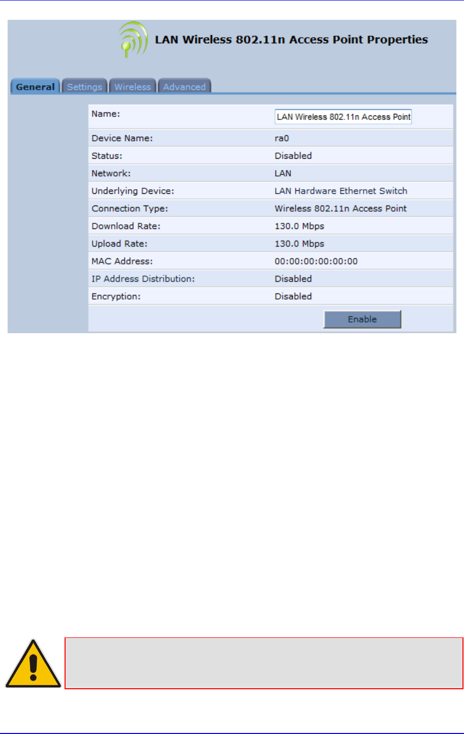
MP252 Multimedia Home Gateway 12. Network Connections
Version 3.4.0 145 June 2011
3. In the ‘Name’ field, enter an arbitrary name for your wireless network.
The General tab also allows you to enable or disable the wireless connection (for more
information, see Section 12.2.1.1 on page 145). In addition, it displays various statistics such
as download and upload rate, and whether encryption is enabled or disabled. These
parameters can be configured using the other tabs, as described in the subsequent sections.
12.2.1.1 Enabling and Disabling the Wireless Network
Once you have configured your MP252 wireless network connection, you can enable and
disable it, as required.
¾ To enable or disable the wireless network, do one of the following:
Press the WiFi button located on the front panel of the MP252 (see Section 3.1.1 on
page 23)
In the ‘LAN Wireless 802.11n Access Point Properties (General Tab)’ screen (see
Section Figure 12-35 on page 144), click the Enable or Disable button.
12.2.1.2 Configuring Wireless Properties under the Settings Tab
The procedure below describes the configurations under the Settings tab of the ‘LAN
Wireless 802.11 Access Point Properties’ screen.
Note: Since your MP252 wireless network is configured to operate with default
settings, it is recommended to leave the settings in this screen at their default
values.
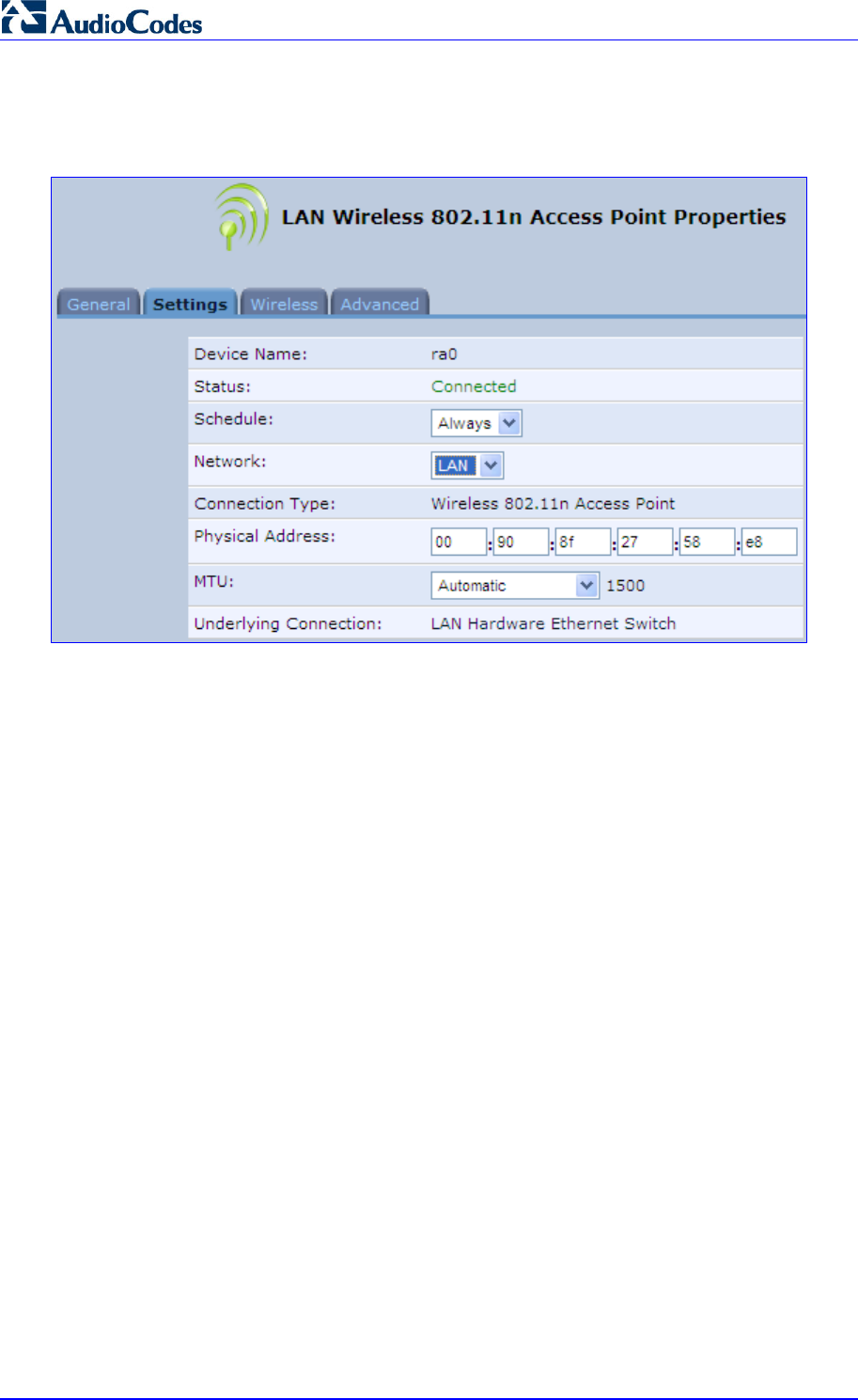
MP252 Multimedia Home Gateway 146 Document #: LTRT-23504
User's Manual
¾ To configure the wireless parameters under the Settings tab:
1. Click the Settings tab.
Figure 12-36: LAN Wireless 802.11 Access Point Properties (Settings Tab) Screen
The ‘Underlying Connection’ read-only field displays the underlying connection upon
which the wireless LAN is defined.
2. From the ‘Scheduler’ drop-down list, select the Scheduler rule during which this network
connection is active. To ensure that the network is always active, select ‘Always’. To
define Scheduler rules, see Section 4.5.1 on page 43.
3. From the ‘Network’ drop-down list, select the network (LAN, WAN, or DMZ) to which this
new network is related.
4. In the ‘Physical Address’ field, define the physical address of the network card used for
your network.
5. From the ‘MTU’ drop-down list, select the largest packet size permitted for Internet
transmission (i.e., MTU / Maximum Transmission Unit). By default, it is set to
'Automatic', whereby MP252 selects the best MTU for your Internet connection. If you
modify this field, ensure that the range is 1200 to 1500.
6. Click OK to save your settings.
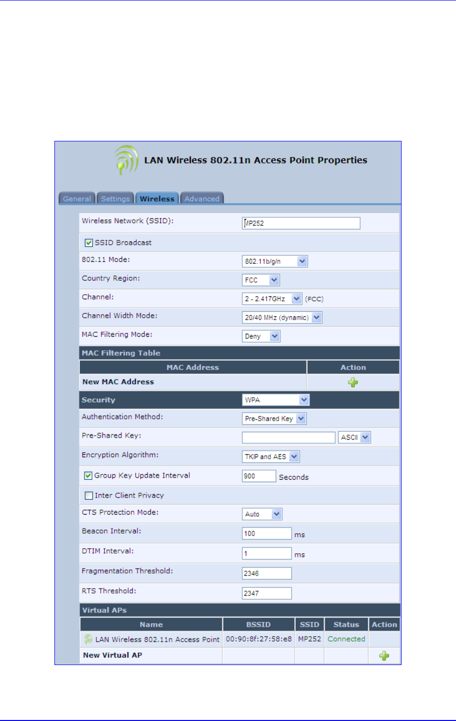
MP252 Multimedia Home Gateway 12. Network Connections
Version 3.4.0 147 June 2011
12.2.1.3 Configuring Wireless Properties under the Wireless Tab
The procedure below describes the configurations under the Wireless tab of the ‘LAN
Wireless 802.11 Access Point Properties’ screen.
¾ To configure the wireless parameters under the Wireless tab:
1. Click the Wireless tab.
Figure 12-37: LAN Wireless 802.11 Access Point Properties (Wireless Tab) Screen
2. Refer to the subsequent sections for a description of the parameters in this screen.
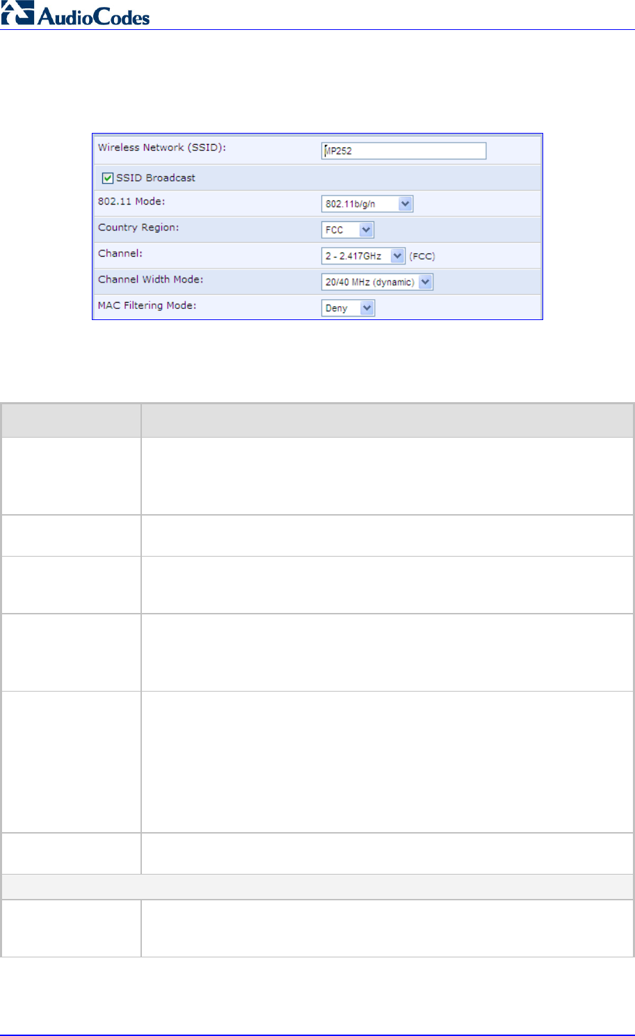
MP252 Multimedia Home Gateway 148 Document #: LTRT-23504
User's Manual
12.2.1.3.1 Wireless Network Group
This group in the Wireless tab screen configures the basic wireless access point settings.
Figure 12-38: Wireless Network Group in Wireless Tab Screen
The table below describes the parameters in this group:
Table 12-1: Wireless Tab – Basic Wireless Access Point Parameters Description
Parameter Description
Wireless Network
(SSID) Enter the name of the wireless network. This name is needed for a wireless
device to attach to your wireless network (see Section 6.2 on page 56).
Note: The default wireless (Wi-Fi) network name (SSID) is “MP252” (and is
unsecured).
SSID Broadcast Select this check box to enable the SSID's broadcast. SSID broadcast is used to
hide the name of the AP (SSID) from clients.
802.11 Mode Select the wireless communication standard that is compatible with your client's
wireless card: 802.11b/g Mixed, 802.11g Only, 802.11b Only, 802.11b/g/n,
802.11g/n, 802.11n Only.
Country Region Select the Wi-Fi country region for allowing only permitted channels
(frequencies) for the region.
Note: This parameter determines the available channel options listed in the
‘Channel’ parameter.
Channel Select the appropriate channel to correspond with your network settings. All
devices in your wireless network must broadcast on different channels to
function correctly.
Note: The available channels depend on the country region (configured by the
‘Country Region’ parameter) in which you are operating MP252. For example, i
f
you selected ‘FCC’ as the country region, the available channels from which you
can select conform to the U.S.A. Regulatory Authority FCC (Federal
Communications Commission).
Channel Width
Mode Select the available transmit data rate of the wireless network: 20 MHz only or
20/40 MHz dynamic.
Virtual APS
Virtual APS You can set up multiple virtual wireless LAN's on MP252. Such virtual wireless
LANs are referred to as "Virtual APs" (virtual access points). For a detailed
description on configuring Virtual APS, see 'Virtual Access Points' on page 154.
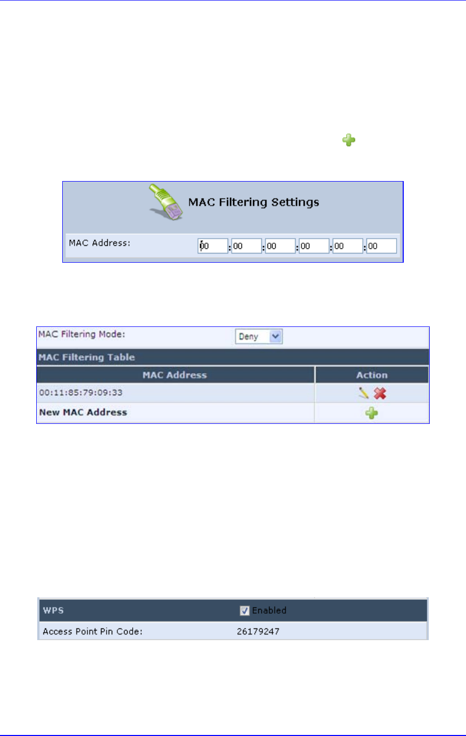
MP252 Multimedia Home Gateway 12. Network Connections
Version 3.4.0 149 June 2011
12.2.1.3.2 Configuring MAC Filtering
The procedure below describes how to filter wireless users according to their MAC
addresses. You can define as list of MAC addresses and for the entire list, either allow or
deny access.
¾ To define MAC filtering:
1. From the 'MAC Filtering Mode' drop-down list, select either 'Allow' or 'Deny' (or ‘Disable’
if you do not want use MAC filtering).
2. In the MAC Filtering Table, click the New MAC Address icon; the 'MAC Filtering
Settings' screen appears.
Figure 12-39: MAC Filtering Settings Screen
3. In the 'MAC Address' field, enter the MAC address to be filtered.
4. Click OK; the MAC address is listed in the MAC Filtering table.
Figure 12-40: MAC Address Added to MAC Filtering Table
12.2.1.3.3 Enabling Wi-Fi Protected Setup (WPS)
The procedure below describes how to enable WPS. WPS is a method for simplifying the
security setup and management of wireless networks. This feature is disabled by default. By
enabling it, you can control the setup of your wireless security, which is defined in the
Security group.
¾ To enable WPS:
Under the WPS group, select ‘Enabled’; an access point pin code is automatically
generated and displayed.
Figure 12-41: WPS Group in Wireless Tab Screen
The access point pin code is an eight digit pin number, provided by the wireless client's
software. When attempting to connect a wireless client to MP252, you must be aware of its
setup method.
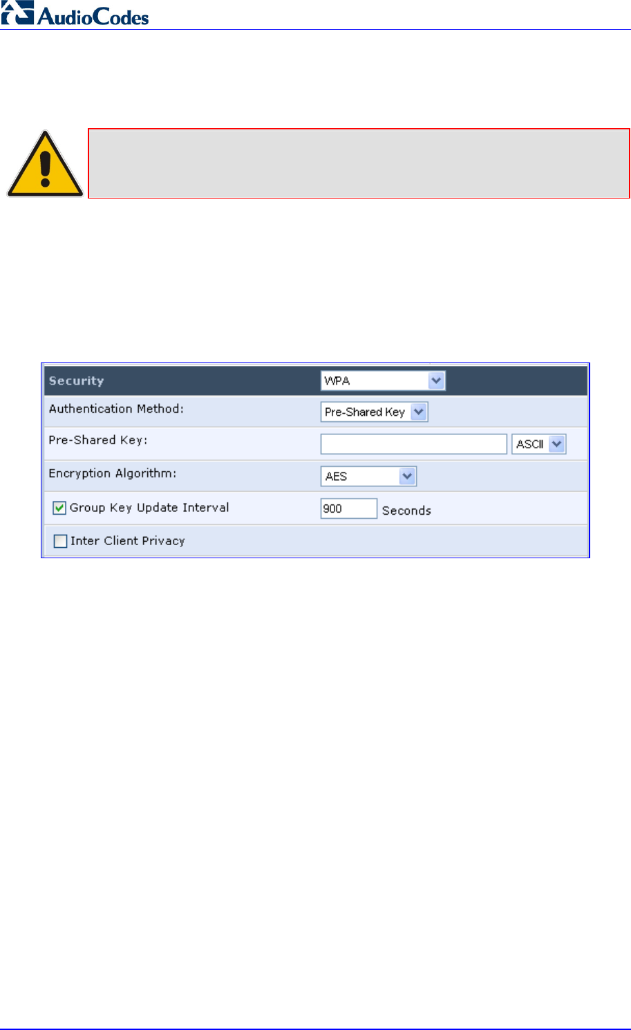
MP252 Multimedia Home Gateway 150 Document #: LTRT-23504
User's Manual
12.2.1.3.4 Configuring Wireless Security
The procedure below describes how to configure wireless security.
Note: WPS supports only the WPA security protocol. Therefore, when enabled (see
Section 12.2.1.3.3 on page 149), only the WPA protocols are available (in the
‘Security’ drop-down list described below).
¾ To define wireless security:
1. From the 'Security' drop-down list, select the type of security protocol; the screen
refreshes, displaying parameters relevant to the selected protocol:
• None: disables security on your wireless connection.
• WPA: WPA is a data encryption method for 802.11 wireless LANs.
Figure 12-42: Configuring WPA Security
Configure the following fields:
b. Authentication Method: select the required authentication method
('Pre-Shared Key' and '802.1x').
c. Pre-Shared Key: this field appears only if you selected ‘Pre-Shared Key’ in
the ‘Authentication Method field. Enter your encryption key (using either an
ASCII or a Hex value), by selecting the value type in the drop-down list
provided.
d. Encryption Algorithm: select 'TKIP' (Temporal Key Integrity Protocol), 'AES'
(Advanced Encryption Standard) or both ('TKIP and AES') for the encryption
algorithm.
e. Group Key Update Interval: select this check box, and then enter the time
interval in seconds for updating a group key.
f. Inter Client Privacy: select this check box to prevent communication
between the wireless network clients using the same access point. When
enable, clients are unable to view and access each other's shared directories.
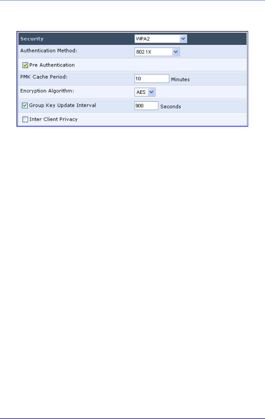
MP252 Multimedia Home Gateway 12. Network Connections
Version 3.4.0 151 June 2011
• WPA2: WPA2 is an enhanced version of WPA, and defines the 802.11i protocol.
Figure 12-43: Configuring WPA2 Security
a. Authentication Method: select the authentication method ('Pre-Shared Key'
and '802.1x').
b. Pre-Shared Key: this field appears only if you selected this authentication
method. Enter your encryption key in either an ASCII or a Hex value (by
selecting the value type in the drop-down list provided).
c. Pre Authentication: This field appears only when selecting the 802.1x
authentication method. Select this option to enable MP252 to accept RADIUS
authentication requests from computers connected to other access points.
This enables roaming from one wireless network to another.
d. PMK Cache Period: This field appears only when selecting the 802.1x
authentication method. This field defines the number of minutes before
deletion (and renewal) of the Pairwise Master Key used for authentication.
e. Encryption Algorithm: encryption algorithm for WPA2 is the Advanced
Encryption Standard (AES).
f. Group Key Update Interval: Defines the time interval in seconds for updating
a group key.
g. Inter Client Privacy: select the check box to prevent communication between
the wireless network clients using the same access point. Clients will not be
able to view and access each other's shared directories.
• WPA and WPA2: WPA and WPA2 is a mixed data encryption method. For a
description of these fields, see WPA and WPA2 above.
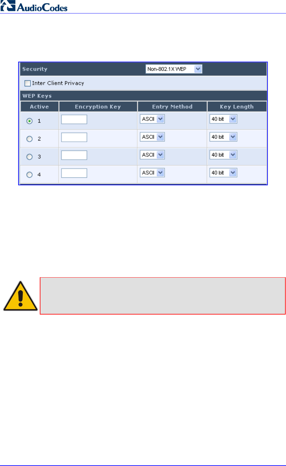
MP252 Multimedia Home Gateway 152 Document #: LTRT-23504
User's Manual
• Non-802.1x WEP: data encryption method utilizing a statically defined key for
wireless clients that do not use 802.1x for authentication, but use WEP for
encryption. You may define up to four keys, but use only one at a time.
Figure 12-44: Configuring Non-WEP Security
a. Inter Client Privacy: select this check box to prevent communication
between the wireless network clients using the same access point. Clients will
not be able to view and access each other's shared directories.
b. WEP Keys table:
9 Active: select the encryption key to be activated.
9 Encryption Key: enter the encryption key until the entire field is filled.
The key cannot be shorter than the field's length.
9 Entry Method: select the character type for the key: ASCII or HEX.
9 Key Length: select the key length in bits: 40 or 104 bits.
Note: The encryption key must be defined in the wireless Windows client as well. This
is done in the Connection Properties Configuration window (your encryption key
is entered in both the 'Network key' and 'Confirm network key' fields, as shown in
the figure below.
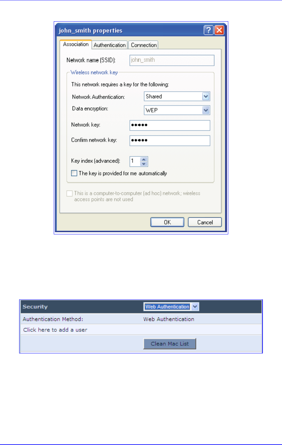
MP252 Multimedia Home Gateway 12. Network Connections
Version 3.4.0 153 June 2011
Figure 12-45: Configuring Encryption Key in Windows Wireless Client
• Web Authentication: wireless clients attempting to connect to the wireless
connection (Internet) receive a Web Authentication screen, requiring the clients to
authenticate themselves before they are able to use the connection. To add a Web
client user, click the Click here to add a user link. MP252 keeps record of
authenticated clients. To clear this list, click the Clean Mac List button. Clients
need to re-authenticate themselves to use the wireless connection.
Figure 12-46: Configuring Authentication Only Security
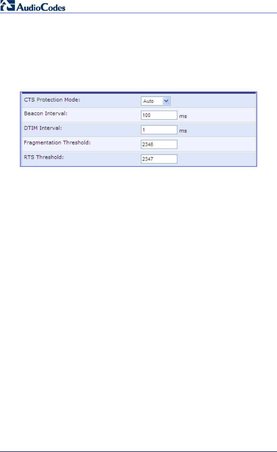
MP252 Multimedia Home Gateway 154 Document #: LTRT-23504
User's Manual
12.2.1.3.5 Configuring Transmission Properties
The procedure below describes how to configure wireless transmission properties.
¾ To configure the transmission properties:
1. Access the Wireless tab screen.
Figure 12-47: Transmission Parameters in Wireless Tab Screen
2. From the ‘CTS Protection Mode’ drop-down list, select whether you want to enable or
disable this feature (‘Always' to enable CTS or 'Auto' to have MP252 automatically
decide whether or not to use this feature). CTS Protection Mode boosts your MP252's
ability to intercept 802.11g and 802.11b transmissions. Conversely, CTS Protection
Mode decreases performance. Leave this feature disabled unless you encounter
severe communication difficulties between MP252 and 802.11g products.
3. In the ‘Beacon Interval’ field, enter how often the beacon packet is sent. A beacon is a
packet broadcast by MP252 to synchronize the wireless network.
4. In the ‘DTIM Interval’ field, enter the Delivery Traffic Indication Message (DTIM)
countdown value that informs wireless clients of the next opportunity to receive
multicast and broadcast messages. This value ranges between 1 and 16384.
5. In the ‘Fragmentation Threshold’ field, enter the packet size threshold above which
packets are fragmented into multiple packets. Try to increase the fragmentation
threshold if you encounter high packet error rates. Do not set the threshold too low,
since this can result in reduced networking performance.
6. In the ‘RTS Threshold’ field, enter the packet threshold size below which the Request to
Send (RTS) / Clear to Send (CTS) mechanism are not active. MP252 sends RTS
packets to the wireless client to negotiate the dispatching of data. The wireless client
responds with a CTS packet, signaling that transmission can commence. If you
encounter inconsistent data flow, try a slight reduction in the RTS threshold size.
12.2.1.3.6 Adding Virtual Access Points
You can set up multiple virtual wireless LAN's on MP252, limited. Such virtual wireless LANs
are referred to as "Virtual APs" (virtual access points). In the Wireless tab's screen, under
the section 'Virtual APs' section, MP252's physical wireless access point is displayed first,
and on top of which virtual connections may be created.
Figure 12-48: Virtual APs Table
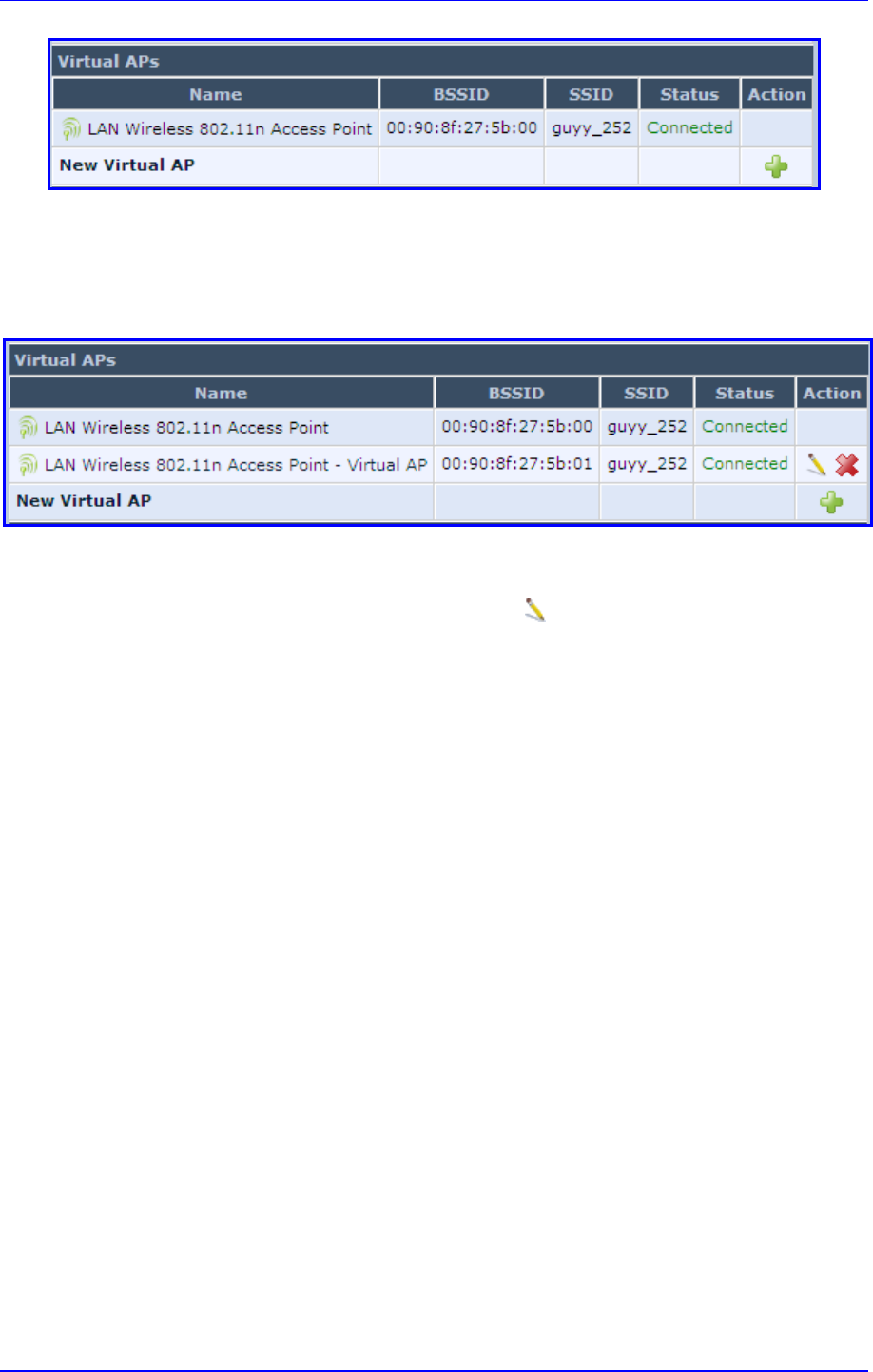
MP252 Multimedia Home Gateway 12. Network Connections
Version 3.4.0 155 June 2011
¾ To create a virtual connection:
1. In the Wireless tab's screen, under the section 'Virtual APs' section, click the New
Virtual AP link; the screen refreshes, displaying the new virtual connection.
Figure 12-49: New Virtual AP
The new virtual connection is also added to the list of connections in the 'Network
Connections' screen (Network Connections menu), and is configurable like any other
connection (by clicking its corresponding Edit icon).
A useful implementation of Virtual AP's is to define a virtual connection with a different SSID
value to dedicate it for guest access. Through this connection, guests are able to access the
WAN, but they are denied access to other wireless LANs provided by MP252. To do so,
perform the following:
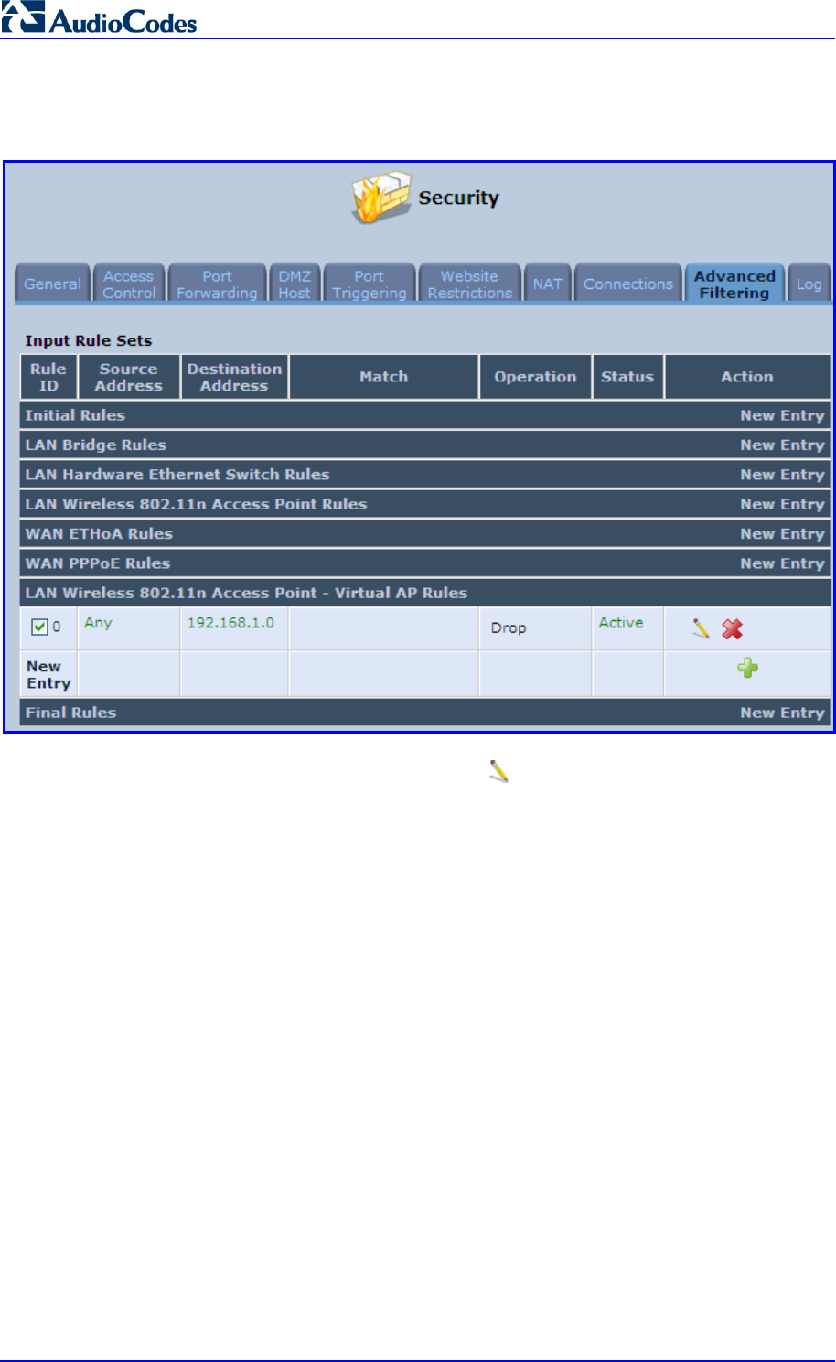
MP252 Multimedia Home Gateway 156 Document #: LTRT-23504
User's Manual
2. Set a firewall rule that blocks access to all other MP252 LANs (Security menu >
Advanced Filtering tab).
Figure 12-50: Firewall Blocking Access to All Other LANs
3. In the Wireless tab's screen, click the Edit icon corresponding to the Virtual AP to
open the virtual connection's 'LAN Wireless 802.11n Access Point - Virtual AP
Properties' screen:
a. In the 'Internet Protocol' section under the 'Settings' sub-tab, enter an IP address
for the connection by selecting 'Use the Following IP Address'.
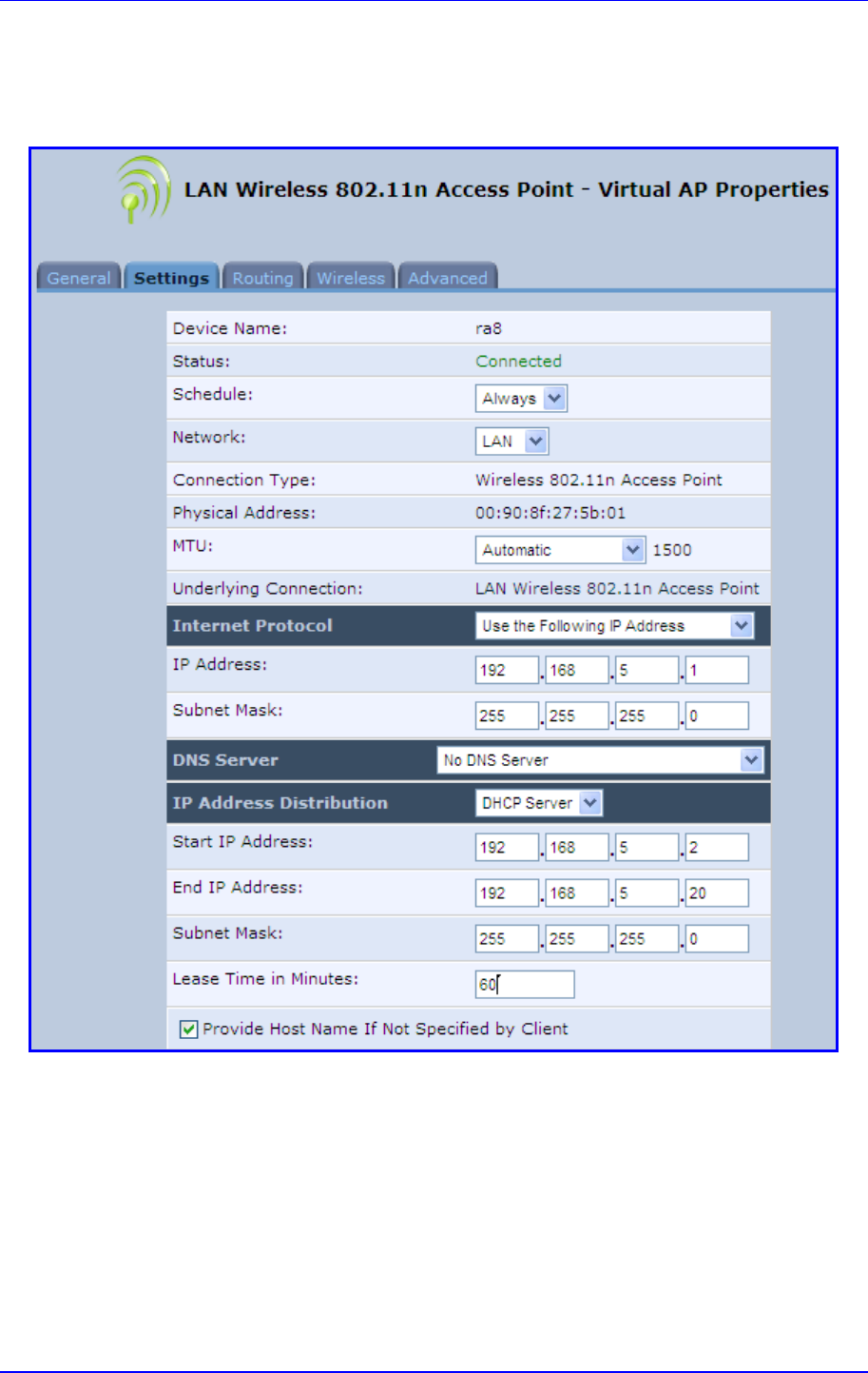
MP252 Multimedia Home Gateway 12. Network Connections
Version 3.4.0 157 June 2011
b. In the 'IP Address Distribution' section, select 'DHCP Server' and enter the IP
range from which IP addresses will be granted to wireless guests.
c. Click OK.
Figure 12-51: Example Virtual AP
After performing this procedure, you have secured all of your wireless connections. A guest
is only able to connect to the "Guests" wireless LAN, from which only the WAN access is
granted.
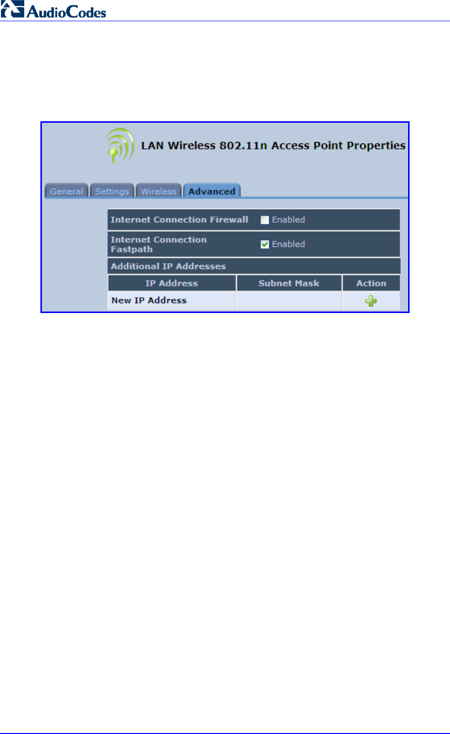
MP252 Multimedia Home Gateway 158 Document #: LTRT-23504
User's Manual
12.2.1.4 Advanced Tab
The Advanced tab allows you to enable your firewall on your wireless network connection as
well as define alias names.
Figure 12-52: Wireless Advanced Tab
Internet Connection Firewall: Your MP252's firewall helps protect your computer by
preventing unauthorized users from gaining access to it through a network such as the
Internet. The firewall can be activated per network connection. To enable the firewall on
this network connection, select the 'Enabled' check box.
Internet Connection Fastpath: Select this check box to utilize the Fastpath algorithm
for enhancing packet flow, resulting in faster communication between the LAN and the
WAN
Additional IP Addresses: You can add alias names (additional IP addresses) to
MP252 by clicking the New IP Address link. This enables you to access MP252 using
these aliases in addition to the IP address (e.g., 192.168.2.1) and http://mp252.home.
12.2.2 LAN Hardware Ethernet Switch
The LAN Hardware Ethernet Switch interface represents the physical ports on MP252.
¾ To configure the LAN hardware Ethernet switch:
4. From the menu bar, click the Network Connections menu; the 'Network Connections'
screen appears.
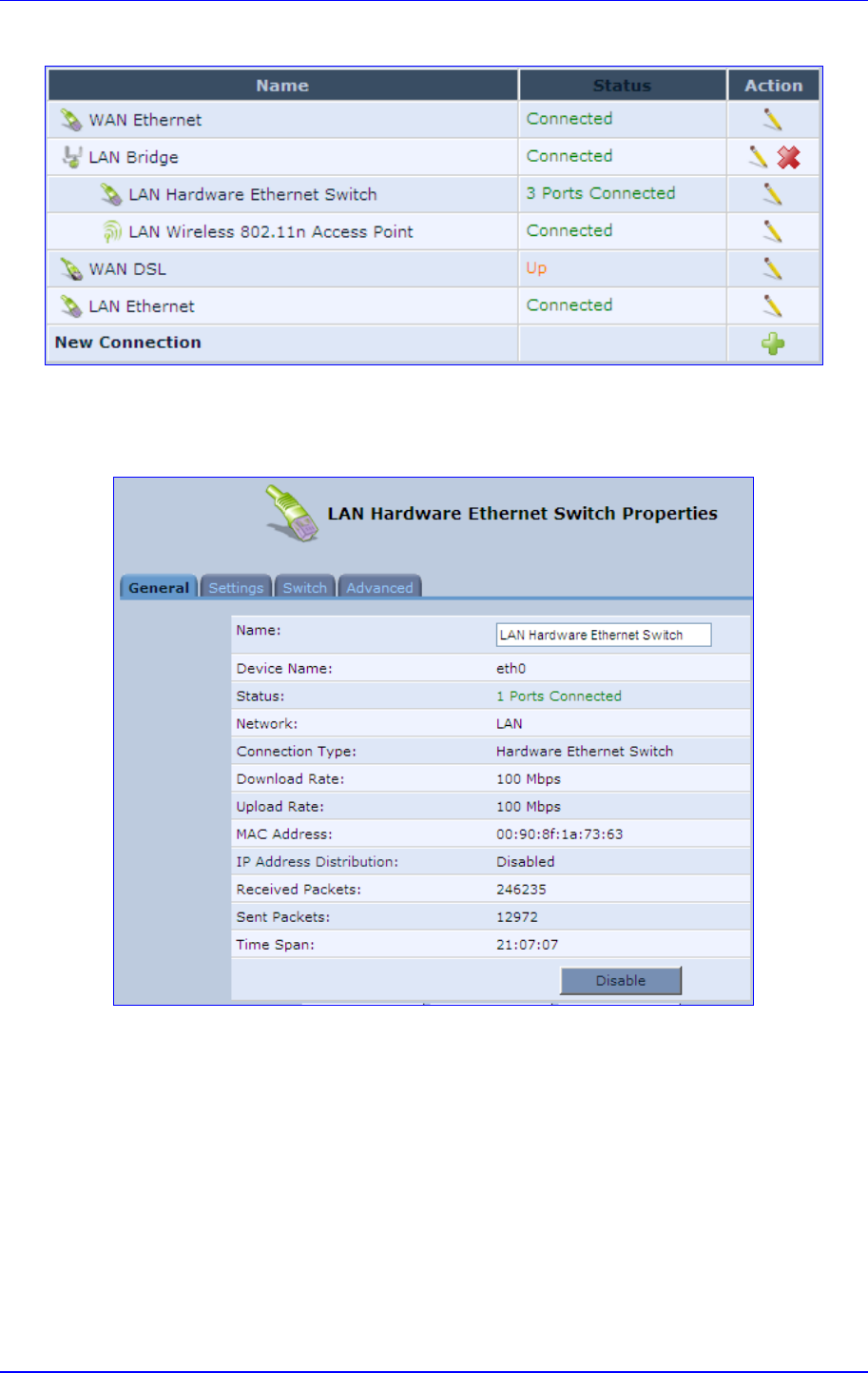
MP252 Multimedia Home Gateway 12. Network Connections
Version 3.4.0 159 June 2011
Figure 12-53: Network Connections Screen
5. Click the LAN Hardware Ethernet Switch link; the LAN Hardware Ethernet Switch
Properties screen appears:
Figure 12-54: LAN Hardware Ethernet Switch Screen
6. The General tab allows you to assign a name to this connection as well as disable or
enable the connection, by clicking the Enable or Disable buttons respectively.
12.2.2.1 Settings Tab
The Settings tab screen is displayed below:
Figure 12-55: LAN Hardware Ethernet Switch Screen – Settings Tab
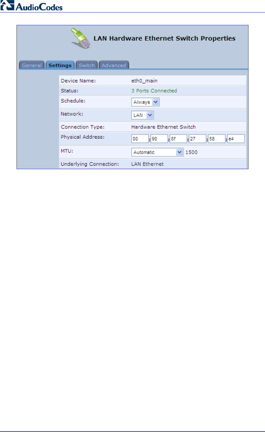
MP252 Multimedia Home Gateway 160 Document #: LTRT-23504
User's Manual
The Settings tab provides you with the following parameters
Schedule: By default, the connection is always active. However, you can configure
scheduler rules to define time segments during which the connection is active. Once a
scheduler rule(s) is defined, the drop-down list allows you to choose between the
available rules.
Network: Select whether the parameters you are configuring relate to a WAN, LAN or
DMZ connection.
Physical Address: The physical address of the network card used for your network.
Some cards allow you to change this address.
MTU: Maximum Transmission Unit. It specifies the largest packet size permitted for
Internet transmission. In the default setting, Automatic, the gateway selects the best
MTU for your Internet connection. Select 'Automatic by DHCP' to have the DHCP
determine the MTU. In case you select 'Manual' it is recommended to enter a value in
the 1200 to 1500 range.
12.2.2.2 Switch Tab
The Switch tab screen is displayed below:
Figure 12-56: LAN Hardware Ethernet Switch Screen – Switch Tab
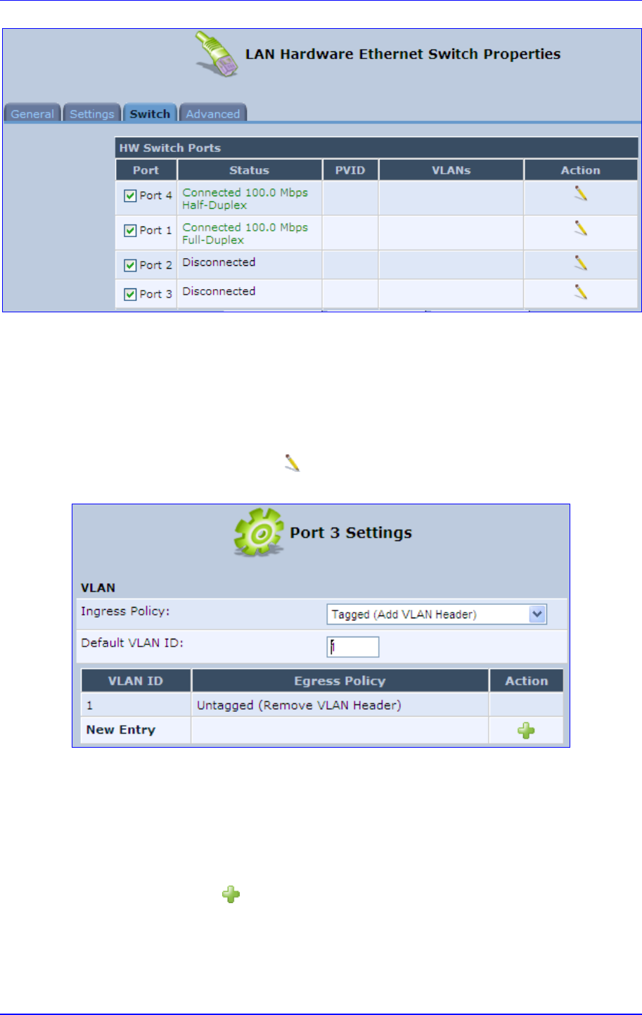
MP252 Multimedia Home Gateway 12. Network Connections
Version 3.4.0 161 June 2011
The Switch tab screen displays the hardware switch ports properties. The switch ports are
physical sockets on the MP252 to which different cables connect. The table in this screen
consists of a list of all available ports, their status, and the VLANs of which they are
members. Untagged packets (packets without a VLAN tag) that arrive at a port are tagged
with the VLAN number that appears under the Port VLAN Identifier (‘PVID’) column.
¾ To edit the configuration of a port:
1. Click a connected port's Edit icon.
Figure 12-57: Port Settings Screen
2. Ingress (incoming packets):
a. From the ‘Ingress Policy’ drop-down list, select whether or not to tag incoming
packets with the port's VLAN header.
b. If the 'Tagged (Add VLAN Header)' option is selected, in the ‘Default VLAN ID’ field,
enter the port's VLAN identifier.
3. Egress (outgoing packets):
a. Click the New icon; the Add Port to a VLAN screen appears.
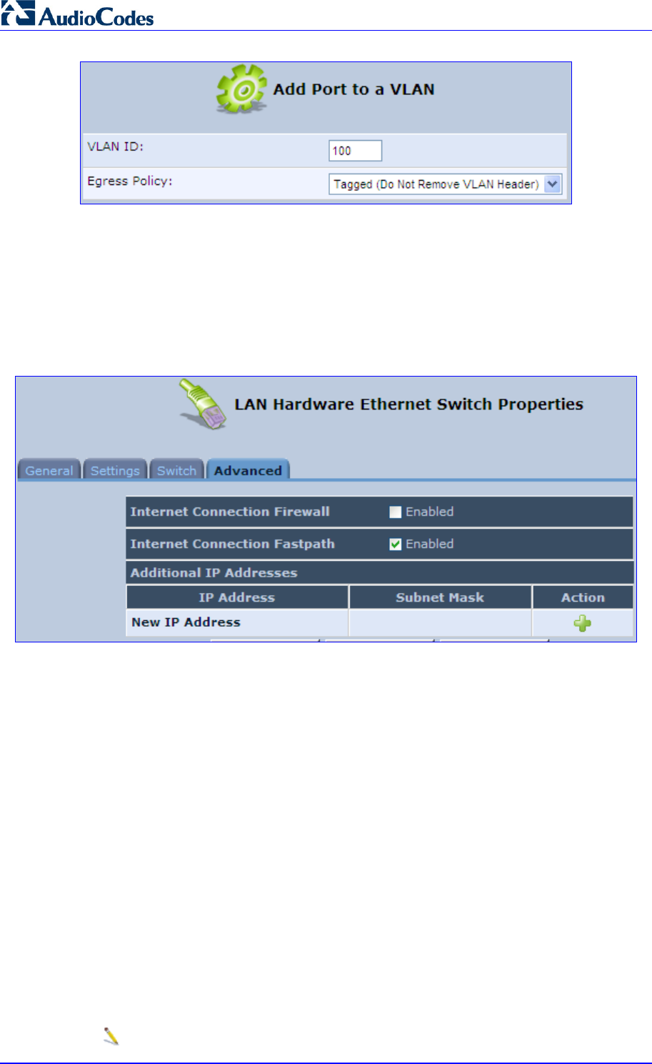
MP252 Multimedia Home Gateway 162 Document #: LTRT-23504
User's Manual
b. In the ‘VLAN ID’ field, enter the VLAN ID for this port.
c. From the ‘Egress Policy’ drop-down list, select whether or not to remove the VLAN
tag from outgoing packets.
12.2.2.3 Advanced Tab
The Advanced tab screen is displayed below:
Figure 12-58: LAN Hardware Ethernet Switch Screen – Advanced Tab
Internet Connection Firewall: Your gateway's firewall helps protect your computer by
preventing unauthorized users from gaining access to it through a network such as the
Internet. The firewall can be activated per network connection. To enable the firewall on
this network connection, select the 'Enabled' check box.
Internet Connection Fastpath: Select this check box to utilize the Fastpath algorithm
for enhancing packet flow, resulting in faster communication between the LAN and the
WAN. By default, this feature is enabled.
Additional IP Addresses: You can add alias names (additional IP addresses) to the
gateway by clicking the 'New IP Address' link. This enables you to access the gateway
using these aliases in addition to the IP address (e.g., 192.168.2.1) and the
http://mp252.home.
12.3 Editing Network Connections and Advanced
Configuration
You can edit created network connections listed in the 'Network Connections' screen. Editing
network connections also allows you to perform additional configuration which is unavailable
when first creating the network connection.
As many of the editing screens are similar between the different network connections, this
section only provides a general description of the screens provided when the connection’s
Edit icon is clicked.
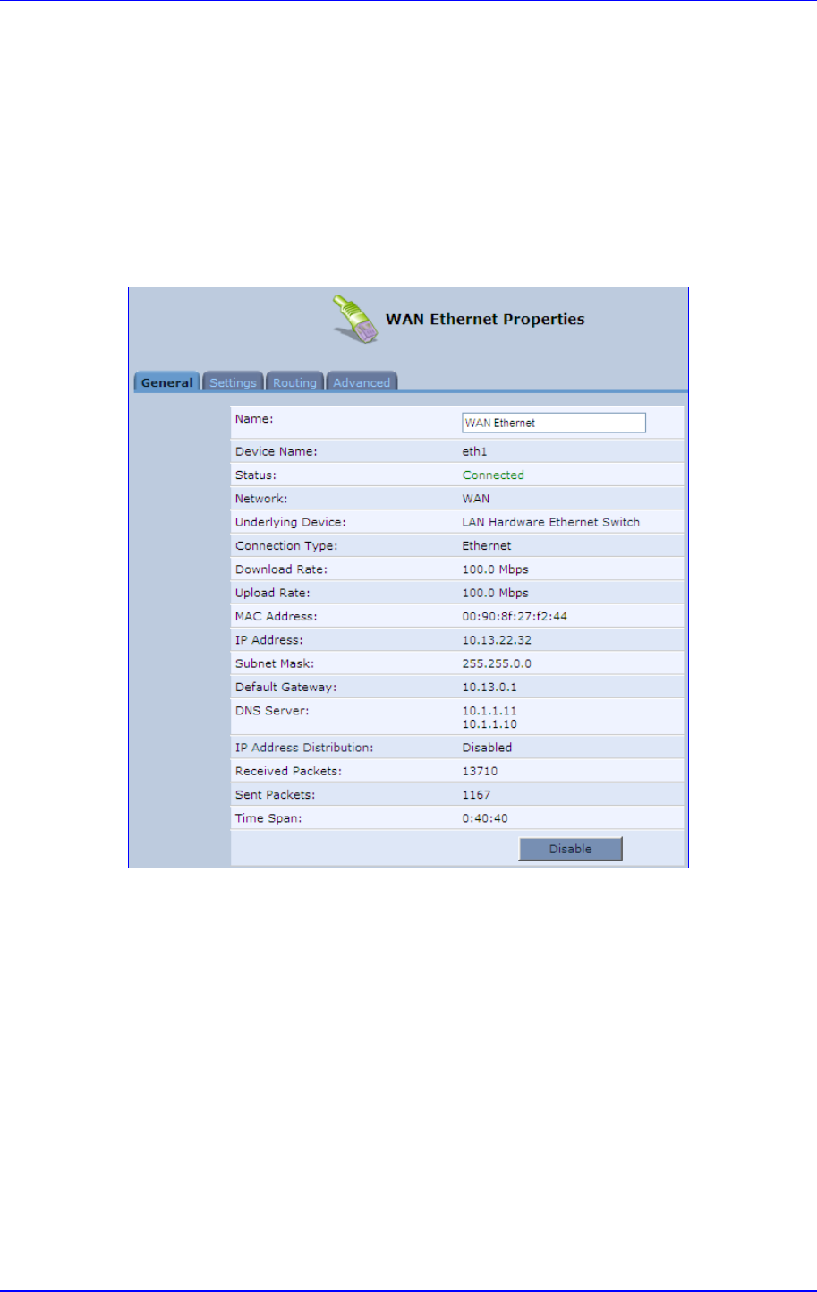
MP252 Multimedia Home Gateway 12. Network Connections
Version 3.4.0 163 June 2011
12.3.1 General Tab
The General tab displays mainly read-only properties of the connection.
The main actions that can be done in this tab screen includes the following:
Modifying the connection name – in the ‘Name’ field
Enabling and disabling the connection, by clicking the Enable or Disable button
respectively
Below shows an example of a General tab screen, displaying the ‘Name’ field and the
Disable button.
Figure 12-59: Editing Connection - General Tab (For Example, WAN Ethernet)
12.3.2 Settings Tab
The top part of the Settings tab screen displays general communication parameters. It is
recommended not to change the default values in this screen unless you are familiar with the
networking concepts they represent. Since your MP252 is configured to operate with the
default values, no parameter modification is necessary.
Figure 12-60: Editing Connection - Settings Tab (For Example, WAN Ethernet)
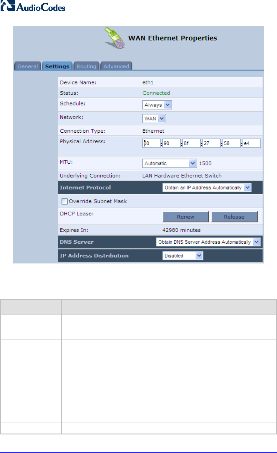
MP252 Multimedia Home Gateway 164 Document #: LTRT-23504
User's Manual
The Settings tab screen allows you to configure the following:
Table 12-2: Settings Tab - Parameter Descriptions
Parameter Description
Schedule You can select a Scheduler rule that defines time segments during which the
connection is active. To configure scheduler rules, see Section 4.5.1 on page
43.
Network Select whether the connection relates to a LAN, WAN, or DMZ connection.
Every network connection can be configured as one of these types. This
provides flexibility and increased functionality. For example, you may define tha
t
a LAN Ethernet connection on MP252 operates as a WAN network. This means
that all hosts in this LAN will be referred to as WAN computers, both by
computers outside MP252 and by MP252 itself. WAN and firewall rules may be
applied, such as on any other WAN network.
Another example, is that a network connection can be defined as a DMZ
(Demilitarized) network. Although the network is physically inside MP252, it will
function as an unsecured, independent network, for which MP252 merely acts
as a router.
Physical Address The physical address of the network card used for your network.
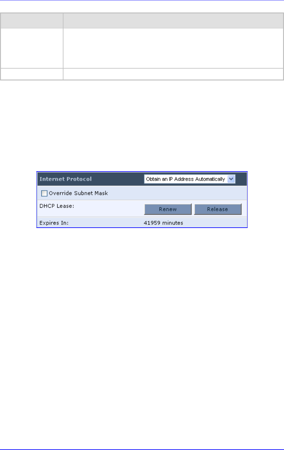
MP252 Multimedia Home Gateway 12. Network Connections
Version 3.4.0 165 June 2011
Parameter Description
MTU Maximum Transmission Unit (MTU) species the largest packet size permitted fo
r
Internet transmission. In the default setting, ‘Automatic’, the MP252 selects the
best MTU for your Internet connection. Select 'Automatic by DHCP' to have the
DHCP determine the MTU. In case you change to ‘Manual’, you can enter the
largest packet size, you should leave this value in the 1200 to 1500 range.
Internet Protocol For a description, see Section 12.3.2.1.
12.3.2.1 Internet Protocol Settings
The 'Internet Protocol' group defines the Internet Protocol options. Select one of the following
Internet Protocol options from the 'Internet Protocol' drop-down list:
No IP Address
Obtain an IP Address Automatically: Your WAN connection is configured by default
to act as a DHCP client. You should keep this configuration in case your service
provider supports DHCP, or if you are connecting using a dynamic IP address.
Figure 12-61: Automatically Obtaining an IP Address
The server that assigns the MP252 with an IP address also assigns a subnet mask. You
can override the dynamically assigned subnet mask by selecting the 'Override Subnet
Mask' check box and specifying your own mask instead.
You can click the Release button to release the current leased IP address. Once the
address has been released, the button text changes to 'Renew'. Use the Renew button
to renew the leased IP address.
For defining DNS and DHCP servers, see sections 12.3.2.1.1 and 12.3.2.1.2
respectively.
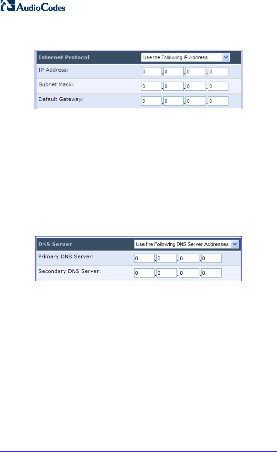
MP252 Multimedia Home Gateway 166 Document #: LTRT-23504
User's Manual
Use the Following IP Address: Your WAN connection can be configured using a
permanent (static) IP address. Your service provider should provide you with this IP
address, subnet mask and the default MP252 IP address.
For defining DNS and DHCP servers, see sections 12.3.2.1.1 and 12.3.2.1.2
respectively.
12.3.2.1.1 DNS Server
Domain Name System (DNS) is the method by which websites or domain names are
translated into IP addresses. You can configure the connection to automatically obtain a
DNS server address, or specify such an address manually, according to the information
provided by your ISP.
From the 'DNS Server' drop-down list, you can select one of the following methods:
Obtain DNS Server Address Automatically: the connection automatically obtains a
DNS server address.
Use the Following DNS Server Addresses: manually configure DNS server - specify
up to two different DNS server addresses - one primary, the other secondary:
Figure 12-62: Manually Defining DNS Server
No DNS Server: select this if there is no DNS server.
12.3.2.1.2 IP Address Distribution
The 'IP Address Distribution' section allows you to configure the device's Dynamic Host
Configuration Protocol (DHCP) server parameters. The DHCP automatically assigns IP
addresses to network PCs. If you enable this feature, make sure that you also configure your
network PCs as DHCP clients.
Select one of the following options from the 'IP Address Distribution' drop-down list:
Disabled: Select this option to statically assign IP addresses to your network
computers.
DHCP Server: Enables DHCP server:
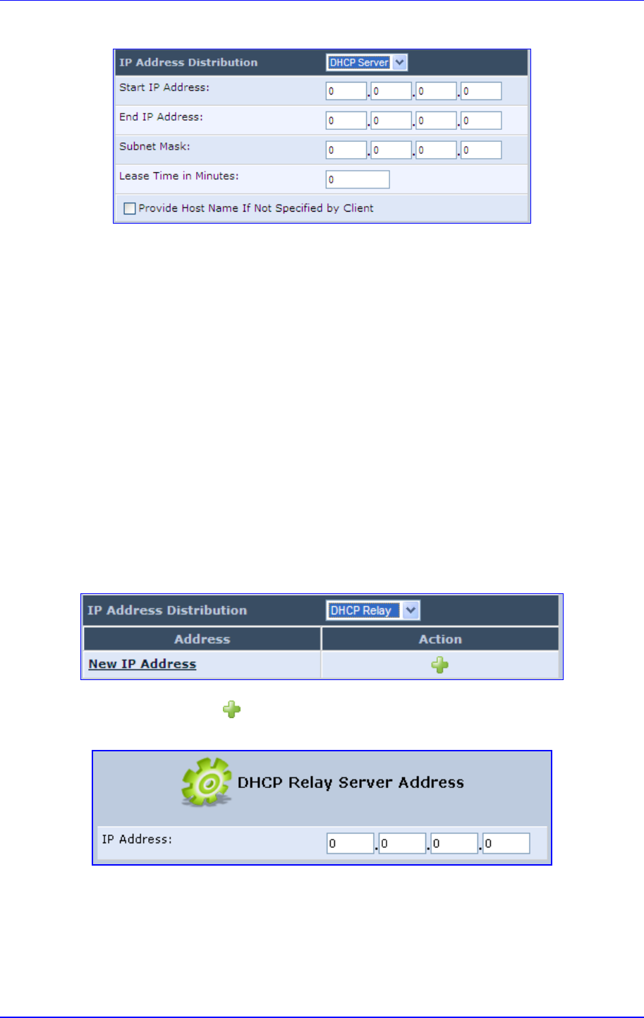
MP252 Multimedia Home Gateway 12. Network Connections
Version 3.4.0 167 June 2011
Figure 12-63: IP Address Distribution - DHCP Server
• Start IP Address: The first IP address that may be assigned to a LAN host. Since
the device's default IP address is 192.168.2.1, this address must be 192.168.2.2 or
greater.
• End IP Address: The last IP address in the range that can be used to
automatically assign IP addresses to LAN hosts.
• Subnet Mask: A mask used to determine to what subnet an IP address belongs.
• Lease Time In Minutes: Each device is assigned an IP address by the DHCP
server for this amount of time when it connects to the network. When the lease
expires, the server determines if the computer has disconnected from the network.
If it has, the server may reassign this IP address to a newly-connected computer.
This feature ensures that IP addresses that are not in use become available for
other computers on the network.
• Provide Host Name If Not Specified by Client: If the DHCP client does not have
a host name, the device automatically assigns one for him
DHCP Relay: The MP252 can act as a DHCP relay in case you would like to
dynamically assign IP addresses from a DHCP server other than MP252's DHCP
server. Note that when selecting this option, you must also change the device's WAN to
work in routing mode.
Figure 12-64: IP Address Distribution - DHCP Relay
1. Click the New icon; the 'DHCP Relay Server Address' screen appears:
Figure 12-65: DHCP Relay Server Address
2. Specify the IP address of the DHCP server, and then click OK to save the settings.
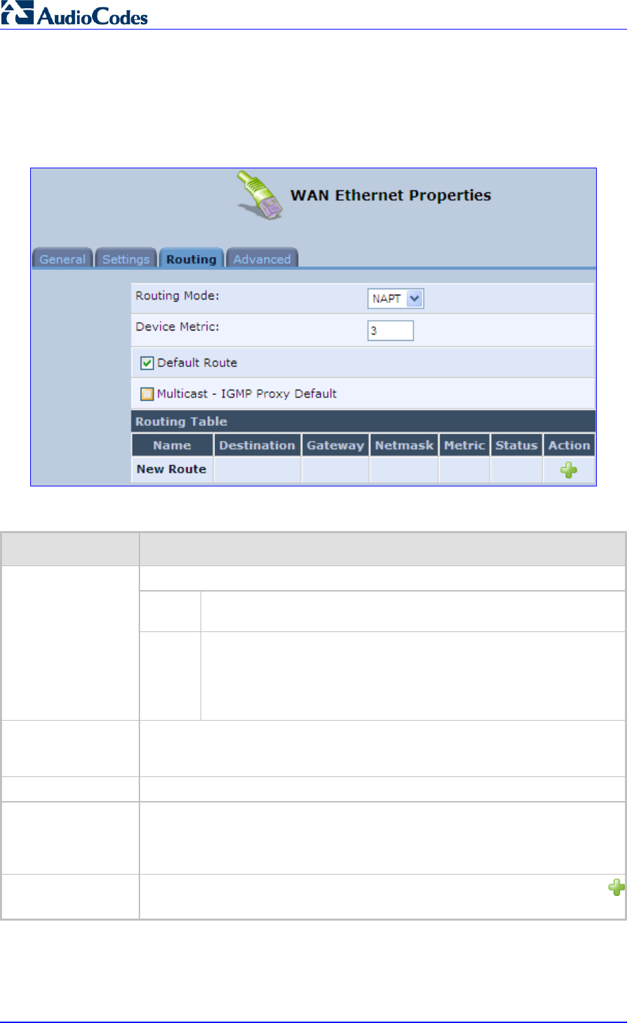
MP252 Multimedia Home Gateway 168 Document #: LTRT-23504
User's Manual
12.3.3 Routing Tab
You can choose to setup your MP252 to use static or dynamic routing. Dynamic routing
automatically adjusts how packets travel on the network, whereas static routing specifies a
fixed routing path to neighboring destinations.
Figure 12-66: Editing Connection - Routing Tab (For Example, WAN Ethernet)
Table 12-3: Routing Parameters
Parameter Description
Select one of the following Routing modes:
Route Use route mode if you want your MP252 to function as a router
between two networks.
Routing Mode
NAPT Network Address and Port Translation (NAPT) refers to network
address translation involving the mapping of port numbers, allowing
multiple machines to share a single IP address. Use NAPT if your LAN
encompasses multiple devices, a topology that necessitates port
translation in addition to address translation.
Device Metric The device metric is a value used by the MP252 to determine whether one route
is superior to another, considering parameters such as bandwidth, delay, and
more.
Default Route Select this check box to define this device as a the default route.
Multicast - IGMP
Proxy Default
IGMP proxy enables the system to issue IGMP host messages on behalf of
hosts that the system discovered through standard IGMP interfaces. IGMP
proxy enables the routing of multicast packets according to the IGMP requests
of LAN devices asking to join multicast groups.
Routing Table Allows you to add or modify routes when this device is active. Click the New
icon to add a route (as shown in the figure below) or edit existing routes.
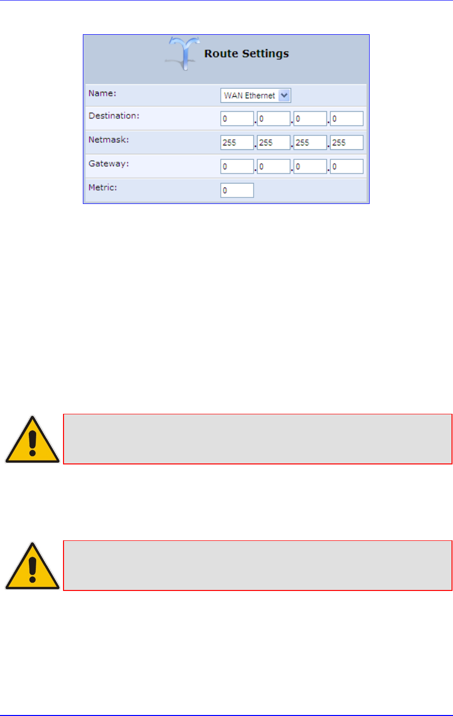
MP252 Multimedia Home Gateway 12. Network Connections
Version 3.4.0 169 June 2011
Figure 12-67: Route Settings Screen
Name: Select the network device.
Destination: destination host, subnet address, network address, or default route. The
destination for a default route is 0.0.0.0.
Netmask: Netmask used in conjunction with the destination to determine when a route
is used.
Gateway: Enter the MP252's IP address.
Metric: A measurement of the preference of a route. Typically, the lowest metric is the
most preferred route. If multiple routes exist to a given destination network, the route
with the lowest metric is used.:
12.3.4 Wireless Tab
For a description of the Wireless tab, see Section Error! Reference source not found. on
page Error! Bookmark not defined..
Note: This tab is applicable only to LAN Wireless connections.
12.3.5 Switch Tab
For a description of the Switch tab, see Section 12.2.2.2 on page 160.
Note: This tab is applicable only to LAN Hardware Ethernet Switch connections.
12.3.6 Bridging Tab
For a description of the Bridging tab, see Section 12.5.1 on page 182.
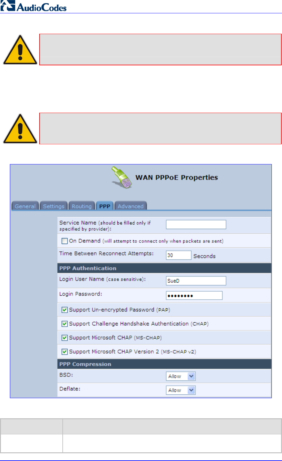
MP252 Multimedia Home Gateway 170 Document #: LTRT-23504
User's Manual
Note: This tab is applicable only to LAN-WAN Bridging connections.
12.3.7 PPP Tab
The PPT tab displays the PPPoE settings.
Note: This tab is applicable only to PPP connections.
Figure 12-68: Editing Connection - PPP Tab
Table 12-4: PPP Tab Parameter Descriptions
Parameter Description
On Demand Use PPP on demand to initiate the PPP session only when packets are actuall
y
sent over the Internet.

MP252 Multimedia Home Gateway 12. Network Connections
Version 3.4.0 171 June 2011
Parameter Description
Idle Time Before
Hanging Up Specify the amount of idle time (during which no data is sent or received) that
should elapse before the gateway disconnects the PPP connection.
Note: This parameter appears only if On Demand is selected.
Time Between
Reconnect
Attempts
Specify the duration between PPP reconnected attempts, as provided by your
ISP.
PPP Authentication PPP supports four authentication protocols: Password Authentication Protocol
(PAP), Challenge Handshake Authentication Protocol (CHAP), Microsoft CHAP
version 1, and Microsoft CHAP version 2.
This section allows you to select the authentication protocols your MP252 may
use when negotiating with a PPTP server. Select all the protocols if no
information is available about the server's authentication protocols. Note that
encryption is performed only if 'Microsoft CHAP', 'Microsoft CHAP version 2', or
both are selected.
Login User Name: login username according to ISP
Login Password: login password according to ISP
Support Un-encrypted Password (PAP): PAP is a simple, plaintext
authentication scheme. The username and password are requested by your
networking peer in plain text. PAP, however, is not a secure authentication
protocol. Man-in-the-middle attacks can easily determine the remote access
client's password. PAP offers no protection against replay attacks, remote
client impersonation, or remote server impersonation.
Support Challenge Handshake Authentication (CHAP): CHAP is a
challenge-response authentication protocol that uses MD5 to hash the
response to a challenge. CHAP protects against replay attacks by using an
arbitrary challenge string per authentication attempt.
Support Microsoft CHAP: Select this check box if you are communicating
with a peer that uses Microsoft CHAP authentication protocol.
Support Microsoft CHAP Version 2: Select this check box if you are
communicating with a peer that uses Microsoft CHAP Version 2
authentication protocol.
PPP Compression The PPP Compression Control Protocol (CCP) is responsible for configuring,
enabling, and disabling data compression algorithms on both ends of the
point-to-point link. It is also used to signal a failure of the compression/
decompression mechanism in a reliable manner. For each compression
algorithm, select one of the following from the drop down menu.
Reject: Reject PPP connections with peers that use the compression
algorithm.
Allow: Allow PPP connections with peers that use the compression
algorithm.
Require: Ensure a connection with a peer is using the compression
algorithm.
12.3.8 PPTP tab
The PPTP tab displays the PPTP settings.
Note: This tab is applicable only to PPTP connections.
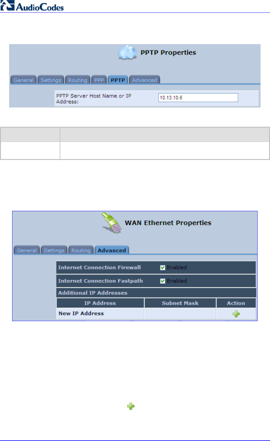
MP252 Multimedia Home Gateway 172 Document #: LTRT-23504
User's Manual
Figure 12-69: Editing Connection - PPTP Tab
Table 12-5: PPTP Tab Parameter Descriptions
Parameter Description
PPTP Server Host
Name or IP Address PPTP server host name or IP address provided by your ISP.
12.3.9 Advanced Tab
The Advanced tab provides various advanced configurations.
Figure 12-70: Editing Connection - Advanced Tab (For Example, WAN Ethernet)
Internet Connection Firewall: Your MP252's firewall helps protect your computer by
preventing unauthorized users from gaining access to it through a network such as the
Internet. The firewall can be activated per network connection. To enable the firewall on
this network connection, select the 'Enabled' check box. You can click the Internet
Connection Firewall link to access the ‘Security’ screen (see Section 14.1 on page
218).
Internet Connection Fastpath: Select this check box to utilize the Fastpath algorithm
for enhancing packet flow, resulting in faster communication between the LAN and the
WAN.
Additional IP Addresses: You can also add alias names (additional IP addresses) to
the MP252, by clicking the New icon. This enables you to access the MP252 using
these aliases in addition to the default IP addresses.
Figure 12-71: Additional IP Address Settings Screen
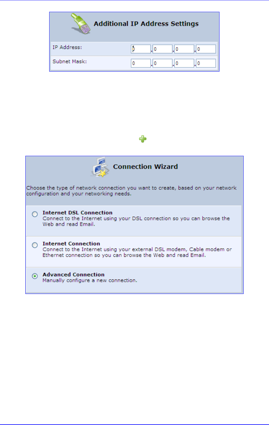
MP252 Multimedia Home Gateway 12. Network Connections
Version 3.4.0 173 June 2011
12.4 VLAN Settings
¾ To create a new VLAN interface:
1. From the menu bar, click the Network Connections menu, and then in the screen
'Network Connections' click the New icon; the 'Connection Wizard' screen appears.
Figure 12-72: Connection Wizard Screen
2. Select the 'Advanced Connection' option, and then click Next; the 'Advanced
Connection' screen appears.
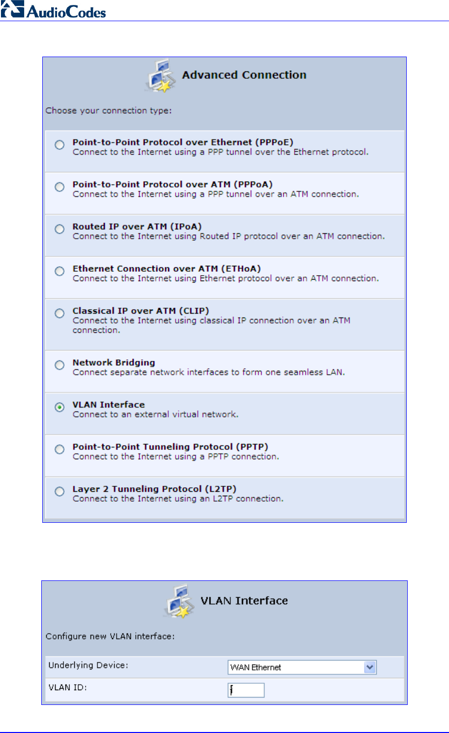
MP252 Multimedia Home Gateway 174 Document #: LTRT-23504
User's Manual
Figure 12-73: Advanced Connection
3. Select the 'VLAN Interface' option, and then click Next; the 'VLAN Interface' screen
appears.
Figure 12-74: VLAN Interface

MP252 Multimedia Home Gateway 12. Network Connections
Version 3.4.0 175 June 2011
4. From the 'Underlying Device' drop-down list, select the underlying device (device's
Ethernet connections) for this interface.
5. In the 'VLAN ID' field, enter a value to serve as the VLAN ID, and then click Next; the
'Connection Summary' screen appears.
Figure 12-75: Connection Summary
6. Check the 'Edit the Newly Created Connection' check box to be routed to the new
connection's configuration screen after clicking Finish.
7. Click Finish to save the settings; the new VLAN interface is added to the network
connections list; it’s configurable like any other connection.
12.4.1 Settings Tab
The Settings tab of the 'VLAN Properties' displays general communication parameters. It’s
recommended to leave the values in this screen at their defaults unless you’re familiar with
the networking concepts they represent. Since your Telephone Adapter is configured to
operate with the default values, no parameter modification is necessary. You can configure
the following general connection settings:
Table 12-6: VLAN Interface - General Communication Parameters
Parameter Description
Schedule By default, the connection is always active. However, you can configure
scheduler rules in order to define time segments during which the connection
may be active. Once a scheduler rule(s) is defined (via Advanced>Scheduler
Rules), this field changes to a drop-down list, allowing you to choose between
the available rules. To configure scheduler rules, see Section 10.11.
Network Select whether the parameters you are configuring relate to a WAN, LAN or
DMZ connection, by selecting the connection type from the drop-down list. For
detailed information, see Section 4.2.
Physical Address The physical address of the network card used for your network.
MTU MTU is the Maximum Transmission Unit. It specifies the largest packet size
permitted for Internet transmission. In the default setting, Automatic, the
Telephone Adapter selects the best MTU for your Internet connection. In case
you change to manual, you can enter the largest packet size, you should leave
this value in the 1200 to 1500 range.
Underlying
Connection The Ethernet device that the connection is implemented over.
Select one of the following Internet Protocol options from the 'Internet Protocol' drop down
menu:

MP252 Multimedia Home Gateway 176 Document #: LTRT-23504
User's Manual
No IP Address
Obtain an IP Address Automatically
Use the Following IP Address
Note that according to the selection you make in the 'Internet Protocol' drop down menu, the
screen refreshes and displays relevant configuration settings.
No IP Address: Select 'No IP Address' if you require that your Telephone Adapter has
no IP address. This can be useful if you are working in an environment where you are
not connected to other networks, such as the Internet.
Obtain an IP Address Automatically: Your WAN connection is configured by default
to act as a DHCP client. You should keep this configuration in case your service
provider supports DHCP, or if you are connecting using a dynamic IP address. The
server that assigns the Telephone Adapter with an IP address also assigns a subnet
mask. You can override the dynamically assigned subnet mask by selecting the
'Override Subnet Mask' and specifying your own mask instead. You can click the
Release button to release the current leased IP address. Once the address has been
released, the button text changes to 'Renew'. Use the Renew button to renew the
leased IP address.
Use the Following IP Address: Your WAN connection can be configured using a
permanent (static) IP address. Your service provider should provide you with this IP
address, subnet mask and the default Telephone Adapter IP address.
12.4.1.1 IP Address Distribution
The 'IP Address Distribution' section allows you to configure the device's Dynamic Host
Configuration Protocol (DHCP) server parameters. The DHCP automatically assigns IP
addresses to network PCs. If you enable this feature, make sure that you also configure your
network PCs as DHCP clients. For a comprehensive description of this feature, see Section
10.28.
Select one of the following options from the 'IP Address Distribution' drop-down list:
Table 12-7: IP Address Distribution Parameters
Parameter Description
DHCP Server Start IP Address The first IP address that may be assigned to a LAN host. Since
the device's default IP address is 192.168.2.1, this address must be 192.168.2.2
or greater.
End IP Address The last IP address in the range that can be used to automatically assign IP
addresses to LAN hosts.
Subnet Mask A mask used to determine to what subnet an IP address belongs. An example o
f
a subnet mask value is 255.255.0.0.
Lease Time In
Minutes Each device is assigned an IP address by the DHCP server for a this amount o
f
time, when it connects to the network. When the lease expires the server
determines if the computer has disconnected from the network. If it has, the
server may reassign this IP address to a newly-connected computer. This
feature ensures that IP addresses that are not in use become available for othe
r
computers on the network.
Provide Host Name If
Not Specified by
Client
If the DHCP client does not have a host name, the device automatically assigns
one for him.
Figure 12-76: IP Address Distribution - DHCP Server
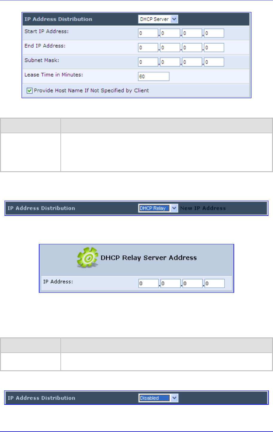
MP252 Multimedia Home Gateway 12. Network Connections
Version 3.4.0 177 June 2011
Table 12-8: DHCP Relay
Parameter Description
DHCP Relay Your device can act as a DHCP relay in case you would like to dynamically
assign IP addresses from a DHCP server other than your Telephone Adapter's
DHCP server. Note that when selecting this option you must also change the
device's WAN to work in routing mode. For detailed information, see Section
10.28.2.
1. After selecting 'DHCP Relay' from the drop down list, a New IP Address link appears:
Figure 12-77: IP Address Distribution - DHCP Relay
2. Click the New IP Address link; the 'DHCP Relay Server Address' screen appears:
Figure 12-78: DHCP Relay Server Address
3. Specify the IP address of the DHCP server.
4. Click OK to save the settings.
Table 12-9: Assigning Static IP Addresses to Network Computers
Parameter Description
Disabled Select 'Disabled' from the drop-down list to statically assign IP addresses to you
r
network computers.
Figure 12-79: IP Address Distribution - Disable DHCP
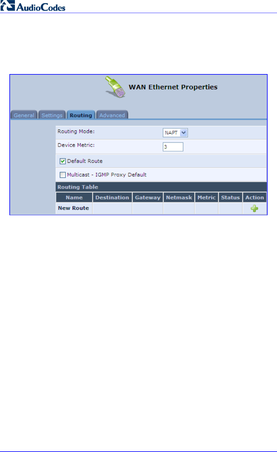
MP252 Multimedia Home Gateway 178 Document #: LTRT-23504
User's Manual
12.4.2 Routing Tab
You can choose to setup your Telephone Adapter to use static or dynamic routing. Dynamic
routing automatically adjusts how packets travel on the network, whereas static routing
specifies a fixed routing path to neighboring destinations.
Figure 12-80: Advanced Routing Properties

MP252 Multimedia Home Gateway 12. Network Connections
Version 3.4.0 179 June 2011
Table 12-10: Routing Parameters
Parameter Description
Routing Select 'Advanced' or 'Basic' routing.
Routing Mode Select one of the following Routing modes:
Route: Use route mode if you want your device to function as a router
between two networks.
NAT: Network Address Translation (NAT) translates IP addresses to a valid,
public address on the Internet. This adds security since internal LAN
addresses are not transmitted over the Internet. In addition, NAT allows
many addresses to exist behind a single valid address. Use the NAT routing
mode if your LAN consists of a single device, otherwise collisions may occu
r
if more than one device attempts to communicate using the same port.
NAPT: Network Address and Port Translation (NAPT) refers to network
address translation involving the mapping of port numbers, allowing multiple
machines to share a single IP address. Use NAPT if your LAN encompasses
multiple devices, a topology that necessitates port translation in addition to
address translation.
Device Metric The device metric is a value used by the device to determine whether one route
is superior to another, considering parameters such as bandwidth, delay, and
more.
Default Route Select this check box to define this device as a the default route.
Multicast IGMP Proxy Internal IGMP proxy enables the system to issue IGMP host
messages on behalf of hosts that the system discovered through standard IGMP
interfaces. IGMP proxy enables the routing of multicast packets according to the
IGMP requests of LAN devices asking to join multicast groups. Select the
'Multicast IGMP Proxy Internal' check-box to enable this feature.
Routing Table Allows you to add or modify routes when this device is active. Use the New
Route button to add a route or edit existing routes.
12.4.3 Advanced Tab
Your Telephone Adapter’s firewall helps protect your computer by preventing unauthorized
users from gaining access to it through a network such as the Internet. The firewall can be
activated per network connection. To enable the firewall on this network connection, select
the 'Enabled' check box. For detailed information on your device's security features, see
Section 5.
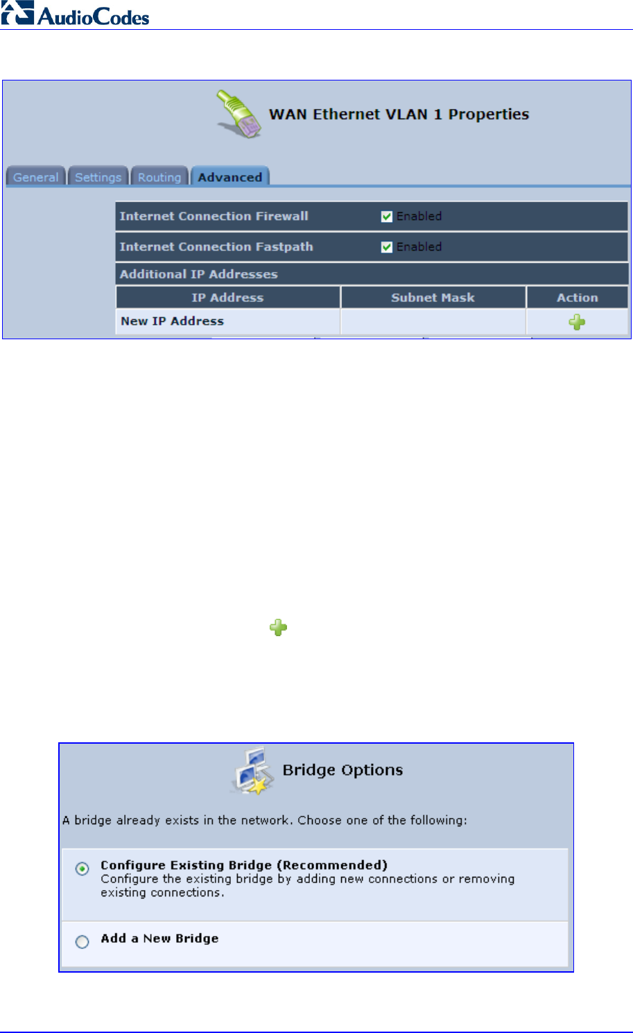
MP252 Multimedia Home Gateway 180 Document #: LTRT-23504
User's Manual
Figure 12-81: Internet Connection Firewall
You can add alias names (additional IP addresses) to the MP252 by clicking the 'New IP
Address' link. This enables you to access the device using these aliases in addition to the IP
address (e.g., 192.168.2.1) and http://mp252.home.
12.5 LAN-WAN Bridge Settings
A WAN-LAN bridge is a bridge over WAN and LAN devices. In such a setup, computers on
the MP252 LAN side can get IP addresses that are known on the WAN side.
¾ To configure an existing bridge or create a new one:
1. From the menu bar, click the Network Connections menu, and in the screen 'Network
Connections' click the New icon; the 'Connection Wizard' screen appears.
2. Select the 'Advanced Connection' option, and then click Next; the 'Advanced
Connection' screen appears.
3. Select the 'Network Bridging' option, and then click Next; the screen 'Bridge Options'
opens.
Figure 12-82: Bridge Options
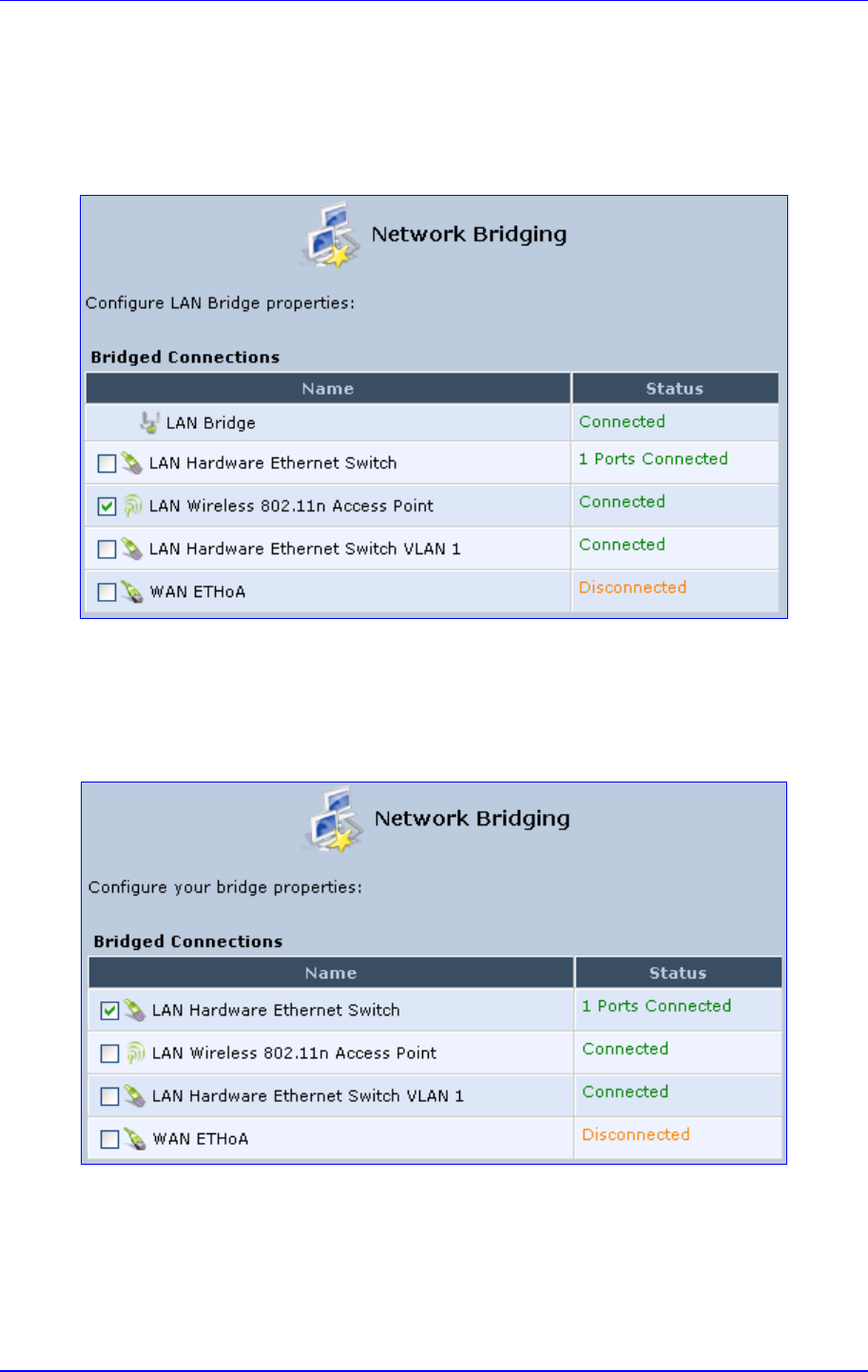
MP252 Multimedia Home Gateway 12. Network Connections
Version 3.4.0 181 June 2011
4. Select whether to configure an existing bridge (this option only appears if a bridge
exists) or to add a new one:
• Configure Existing Bridge: Select this option and then click Next; the screen
'Network Bridging' opens, allowing you to add new connections or remove existing
ones, by selecting or clearing their respective check boxes.
Figure 12-83: Network Bridging Screen
For example, checking the WAN check box creates a LAN-WAN bridge.
• Add a New Bridge: Select this option and then click Next; a different 'Network
Bridging' screen appears, allowing you to add a bridge over the unbridged
connections, by selecting their respective check boxes.
Figure 12-84: Adding New Network Bridging
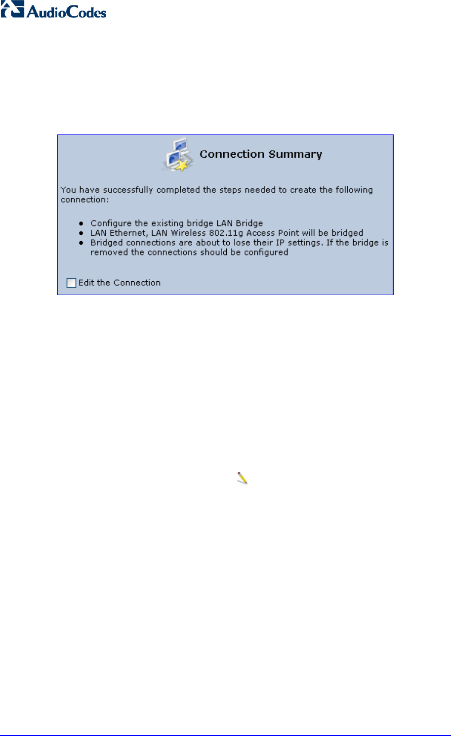
MP252 Multimedia Home Gateway 182 Document #: LTRT-23504
User's Manual
Important notes:
• The same connections cannot be shared by two bridges.
• A bridge cannot be bridged.
• Bridged connections lose their IP settings.
5. Click Next; the screen 'Connection Summary' opens, corresponding to your changes.
Figure 12-85: Connection Summary - Configure Existing Bridge
6. Select the check box 'Edit the Connection' to be routed to the new connection's
configuration screen after clicking Finish.
7. Click Finish to save the settings; the new bridge is added to the network connections
list; it's configurable like any other bridge.
12.5.1 Editing LAN-WAN Bridging
You can edit existing LAN-WAN bridges that are listed in the Connections list. This is done in
the Bridging tab, which allows you to specify the LAN and WAN devices that you would like
to join under the network bridge.
¾ To edit LAN-WAN bridging:
1. From the menu bar, click the Network Connections menu, and then in the screen
'Network Connections' click the Edit icon corresponding the bridged network; the
'Connection Wizard' screen appears.
2. Click the Bridge tab; the LAN Bridge Properties screen appears.
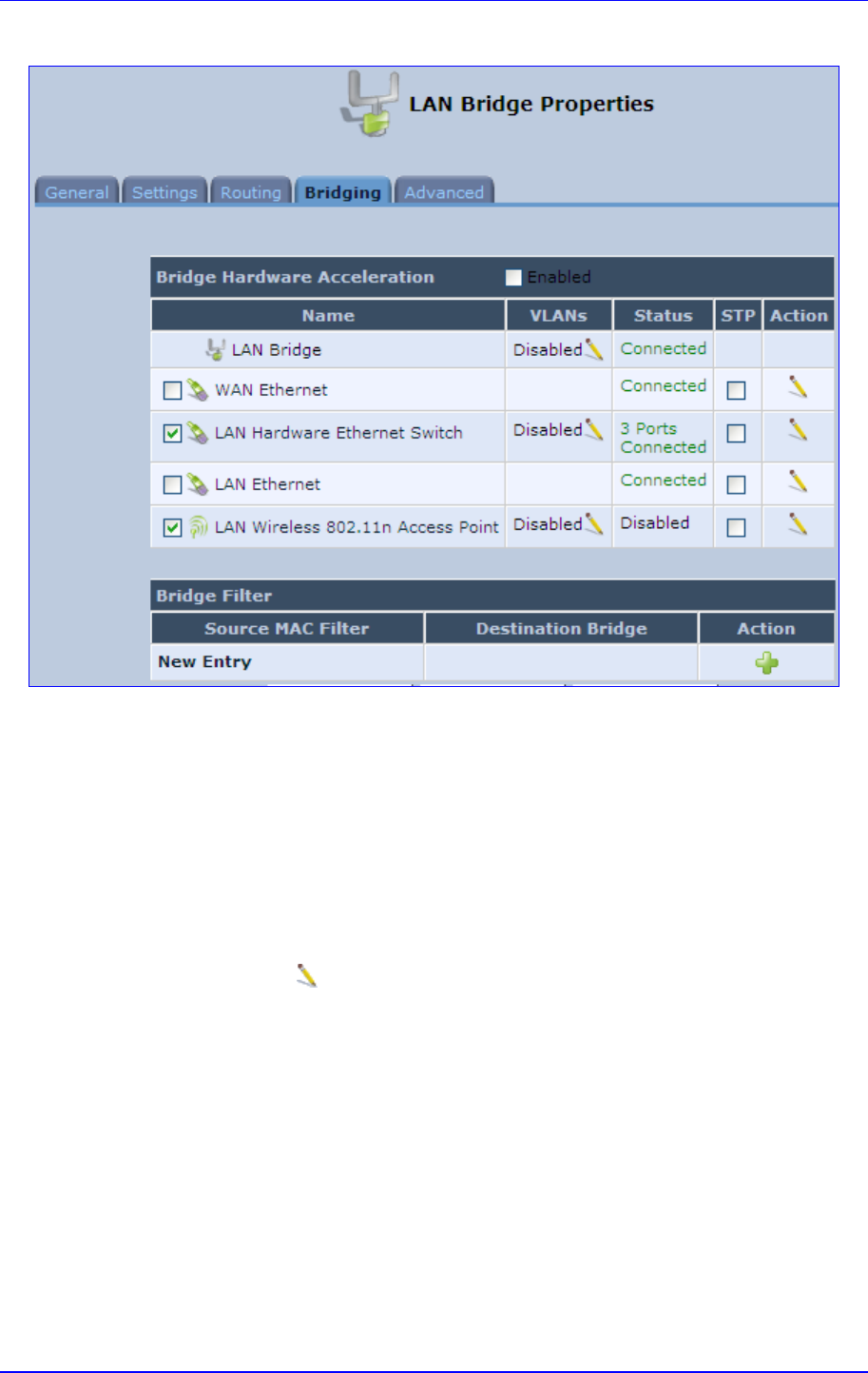
MP252 Multimedia Home Gateway 12. Network Connections
Version 3.4.0 183 June 2011
Figure 12-86: Bridging Tab
3. Select the check boxes corresponding to the connection names that you want to bridge,
or clear the check boxes of connections that you do not want to bridge.
4. Select the ‘Bridge Hardware Acceleration’ check box to utilizes the Fastpath algorithm,
which enhances packet flow, resulting in faster communication between the LAN and
the WAN (excluding the wireless connection).
5. Select the 'STP' check box to enable the Spanning Tree Protocol (STP) on the device.
You should use this to ensure that there are no loops in your network configuration, and
apply these settings if your network consists of multiple switches, or other bridges apart
from those created by the MP252
6. To configure VLANs for each network connection in the bridge:
a. Click the Edit icon in the 'VLANs' column corresponding to a network that you
want to assign specific Virtual LANs; the ‘VLAN Settings’ screen appears.
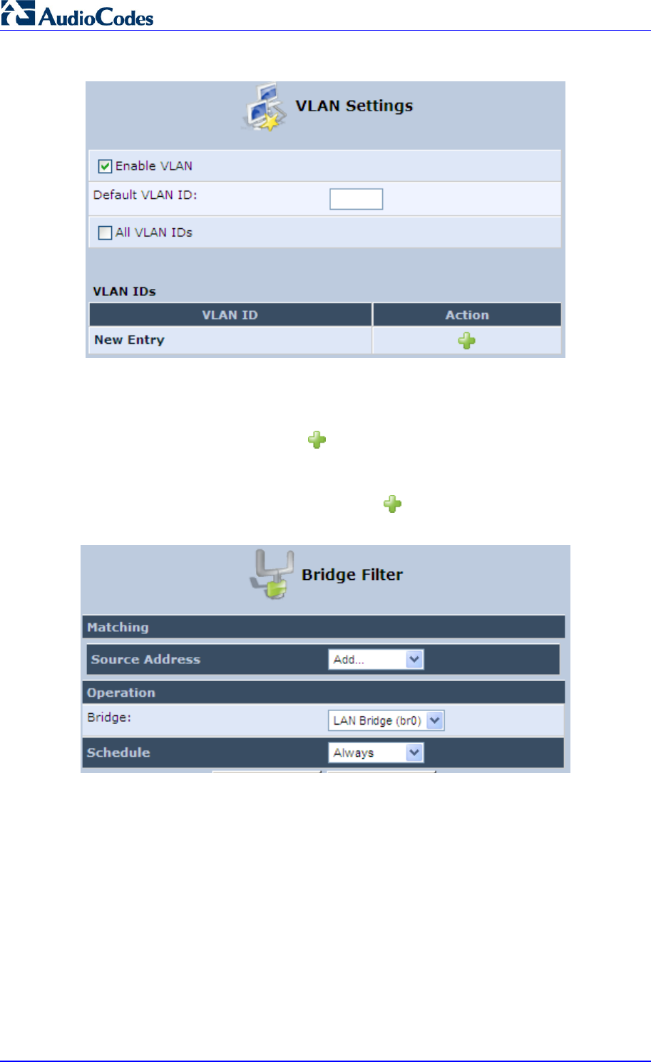
MP252 Multimedia Home Gateway 184 Document #: LTRT-23504
User's Manual
Figure 12-87: VLAN Settings Screen
b. Select the ‘Enable VLAN’ check box to enable VLANs on this connection; the
screen refreshes and additional parameters appear.
c. In the ‘Default VLAN ID’ field, enter a VLAN ID for this connection or add additional
VLANs by clicking the New icon, and then enter another VLAN ID.
7. To create a traffic filtering rule on the bridge to enable direct packet flow between the
WAN and the LAN (i.e., Bridge Filtering):
a. In the ‘Bridge Filter’ table, click the New icon; the ‘Bridge Filter’ screen appears.
Figure 12-88: Bridge Filter Screen
b. From the ‘Source Address’ drop-down list, select a Network Object (defined in
Section 4.5.2 on page 46) or create a new one by clicking ‘User Defined’. You can
define a traffic filtering rule that enables direct packet flow between the WAN and
the LAN host that will be placed under the WAN-LAN bridge. This filtering rule can
be based on either a LAN host's MAC address or one of its DHCP options.
c. From the 'Operation' drop-down list, select the bridge.
d. Click OK.

Version 3.4.0 185 July 2011
MP252 Multimedia Home Gateway 13. Remote MP252 Management
13 Remote MP252 Management
This chapter provides an overview of the MP252 remote configuration and management
support. In addition, this chapter describes how to enable and secure remote management,
as well configure MP252 through SNMP and TR069.
13.1 Overview
MP252 is designed to be mass-deployed. One of the keys to guarantee end-user satisfaction
and true toll-quality service in mass field deployment is comprehensive remote configuration
and management capabilities:
Automatic and remote configuration updates
Automatic and remote firmware updates
Remote diagnosis of problems reported by the user
Remote collection of statistical information regarding the quality of the service
Remote notifications of problems in the service
13.1.1 Remote Configuration
By default, MP252 is provided with factory default settings, which are common to all MP252
devices (except for the MAC address). The factory settings allow the user to connect to
MP252's Web interface through the LAN.
By default, the WAN interface is configured for DHCP (i.e., automatically obtains its IP
address from a DHCP server). The default configuration should not include any VoIP service
provider settings (such as a SIP proxy).
In some cases, AudioCodes can ship MP252 devices that are pre-configured with some
customer-specific parameters. This set of parameters is usually defined as the new "factory
settings" for the specific customer.
MP252's factory default settings and the current configuration running on MP252 are stored
on MP252's non-volatile flash memory. The current configuration can be remotely updated
using several configuration interfaces:
HTTP-based Web server
SNMP
TR-069
Configuration file upload/download
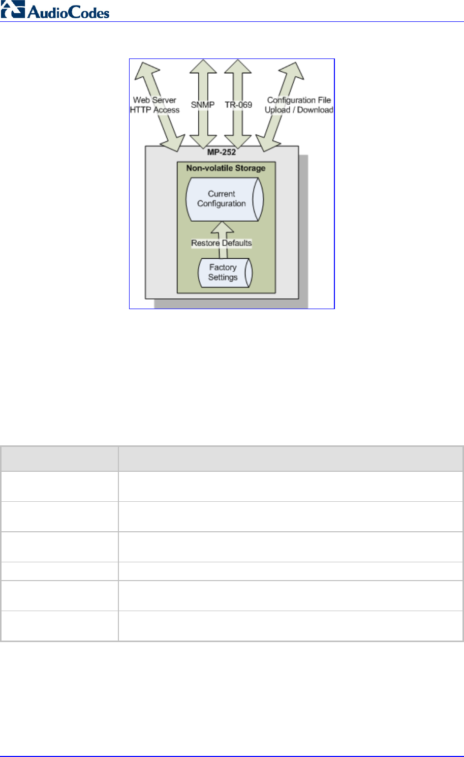
MP252 Multimedia Home Gateway 186 Document #: LTRT-23504
User's Manual
Figure 13-1: Remote Management Interfaces
All configuration interfaces access the same internal configuration repository. The
configuration file represents the complete set of MP252 configuration parameters. Specific
configuration interfaces (e.g. SNMP and TR-069) might support access only to a sub-set of
these configuration parameters.
At any time, the factory settings can be restored using the Web interface or by pressing the
Reset pin-hole button while MP252 is being powered up.
The table below lists the main MP252 configuration parameter groups:
Table 13-1: Main Configuration Parameter Groups
Group Description
VoIP Parameters relating to the VoIP functionality (e.g. analog interface, SIP
signaling, voice and fax, media streaming)
WAN Interface The main WAN Internet connection (this group is also referred to as the
"Quick Setup").
Network Connections Configuration of all network connections (LAN and WAN), including
advanced connections such as VLANs.
Security Parameters relating to the internal firewall.
QoS Configuration of Quality of Service parameters such as priorities and traffic
shaping.
System / Advanced Configuration of system parameters such as Remote Update and Remote
Access and advanced parameters such as Dynamic DNS, UPnP.
A typical set of parameters that a service provider may want to configure include the
following:
Remote access and/or automatic firmware and configuration update parameters
VoIP configuration: SIP proxy, line settings (User IP, Password)
QoS parameters (e.g. traffic shaping)
13.1.2 Remote Management
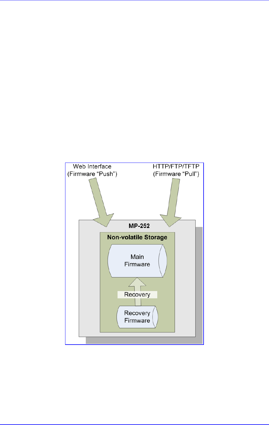
MP252 Multimedia Home Gateway 13. Remote MP252 Management
Version 3.4.0 187 June 2011
Remote management includes the following:
Firmware upgrade
Status and performance monitoring
Alarms, notifications, and logs
13.1.2.1 Firmware Upgrade
Service providers require the ability to update MP252's firmware in the field (e.g. in case of
maintenance releases or releases that support new required features). The process is
required to be automatic, allowing mass update, which is robust and fail-safe.
MP252's firmware is stored on the non-volatile flash memory. MP252's flash memory is
capable of storing a recovery firmware that ensures a fail-safe operation (even if the user
unplugs the power during the firmware burning process).
MP252's firmware can be upgraded using one of the following mechanisms:
The new firmware can be "pushed" (uploaded) to MP252, using the MP252 Web
interface
The new firmware can be "pulled" (downloaded) by MP252 from a remote HTTP, FTP,
or TFTP server
Figure 13-2: Firmware Upgrade Mechanism
MP252 Multimedia Home Gateway 188 Document #: LTRT-23504
User's Manual
The remote firmware download process can be triggered by one of the following:
MP252 checks for a new firmware upon MP252 restart
MP252 periodically checks for a new firmware
Manual trigger using CLI, TR-069, SNMP or Web
Note: Unless forced, MP252 downloads and upgrades to the new firmware only if its
version number is higher than the firmware version currently running on MP252.
The version number is not taken from the image file name, but from the header
of the image file.
13.1.2.2 Status and Performance Monitoring
The ability to remotely monitor the status of MP252 is critical to the service provider, who
wants to support users without having to send a technician on site (avoiding the "truck roll").
The service provider may want to know the current status of MP252 (e.g. is it registered to
the SIP proxy, is the phone off-hook) or some statistical information (e.g. average packet loss
during a call).
MP252 maintains a set of status and performance information internally. This information (or
parts of it) can be retrieved via the different management interfaces (e.g. Web, or TR-069).
The table below describes the status and performance monitoring (statistical) information
available in MP252.
Table 13-2: Status and Performance Monitoring Parameters
Group Description
VoIP Current status information per line:
9 Phone state
9 Registration status
9 Source, codec and type of current call
9 Packet loss, jitter and delay of current call
Network Connections Current status information per interface:
9 Connection status
9 Allocated IP address
9 Received and transmitted packets
System Software version information
Hardware version information
System Up time

MP252 Multimedia Home Gateway 13. Remote MP252 Management
Version 3.4.0 189 June 2011
13.1.2.3 Alarms, Notifications and Logging
Instead of periodically polling MP252 to obtain its current status, the service provider may
want MP252 to notify abnormal events or to send regular reports to a logging server. Both
options are supported by MP252. The table below lists the relevant interfaces for alarms and
notifications.
Table 13-3: Notifications and Logged Events
Group Notifications and Logged Events
VoIP Notifications: Registration error or timeout
Logged Events:
9 End of call (Call Detail Record logging)
9 SIP messages logging (optional - for debugging)
Network Connections Notifications: Connection up / down
Security Logged Events: Security log (configurable)
System Notifications:
9 System restart
9 Firmware / configuration update
Logged Events: Debug-level logging (optional)
Note that the terms Alarm and Notification represent the same thing. The difference between
alarm/notification and logging is that an alarm is normally used to represent an abnormal
event (e.g. registration error), while logged events can represent either regular events (e.g.
end of call) or abnormal events.
The table below lists the event severity levels defined in MP252. Typically, events with
severity of Error or Emergency are notified in addition to being logged.
Table 13-4: Severity of Logged Events
Severity Description
Debug Debug-level messages.
Notice Normal but significant condition. Notices requiring attention at a later time.
Non-error conditions that might require special handling.
Error Recoverable / temporary error condition.
Emergency System is unusable. The most severe messages that prevent continuation o
f
operation, such as immediate system shutdown.
13.2 Enabling Remote Management
You can access and manage MP252 not only from within the home network, but also from
the Internet. This allows you to view or change settings while travelling. It also enables you to
allow your ISP to change settings or help you troubleshoot functionality or communication
issues from a remote location.
Remote access to MP252 is blocked by default to ensure the security of your home network.
However, remote access is supported by the following services, and you may use the
'Remote Access Configuration' screen to selectively enable these services if they are
needed.

MP252 Multimedia Home Gateway 190 Document #: LTRT-23504
User's Manual
Notes:
• Telnet and Web-Management can be used to modify the settings of the
firewall or to disable it. You can also change local IP addresses and other
settings, making it difficult or impossible to access MP252 from the home
network. Therefore, remote access to Telnet or HTTP services should be
blocked and should only be permitted when absolutely necessary.
• Encrypted remote administration is done using a secure SSL connection
that requires an SSL certificate. When accessing MP252 for the first time
using encrypted remote administration, you are prompted by your browse
r
with a warning regarding certificate authentication. This is because
MP252's SSL certificate is self generated. When encountering this
message under these circumstances, ignore it and continue. It should be
noted that even though this message appears, the self-generated
certificate is safe, and provides you with a secure SSL connection. You
can also assign a user-defined certificate to MP252.
¾ To enable remote access to MP252 services:
1. In the 'Advanced' screen, click the Remote Administration icon; the 'Remote
Administration' screen appears.
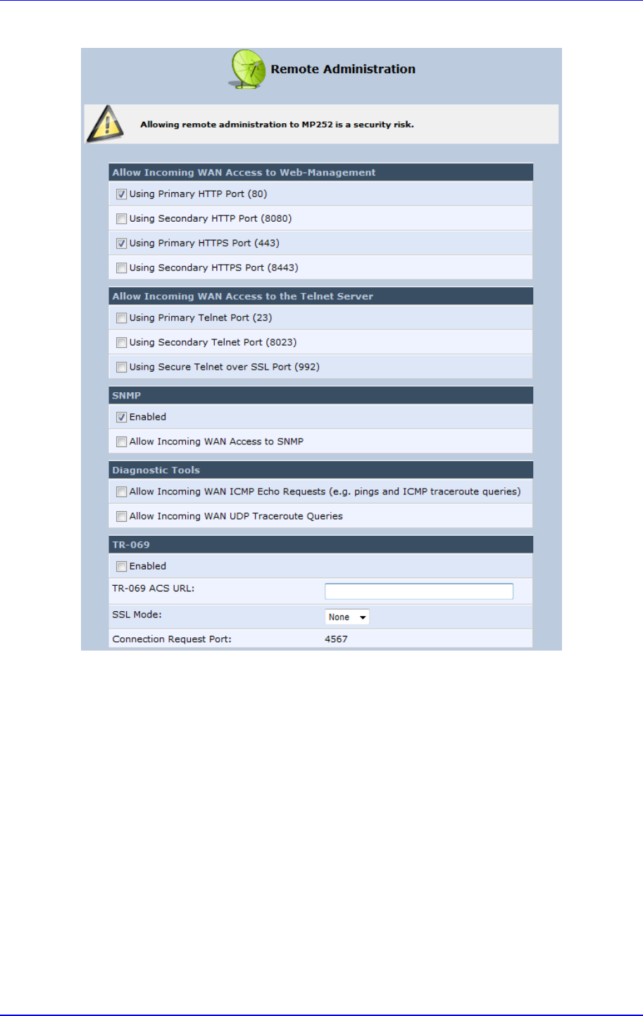
MP252 Multimedia Home Gateway 13. Remote MP252 Management
Version 3.4.0 191 June 2011
Figure 13-3: Remote Administration Screen
2. Select the services that you would like to make available to computers on the Internet.
• Allow Incoming WAN Access to Web-Management: Allows access (from a Web
browser) to the Web management interface and to all system settings and
parameters. Both secure (HTTPS) and non-secure (HTTP) access is available.
• Allow Incoming WAN Access to the Telnet Server: Allows access to the
command-line session and to all system settings and parameters (using a
text-based terminal).
• SNMP: Allows Simple Network Management Protocol (SNMP) requests to
remotely configure and monitor MP252.
• Diagnostic Tools: Allows remote access for ping and traceroute (over UDP)
troubleshooting.
• TR-069: TR-069 is a WAN management protocol for communication between
Customer Premise Equipment (CPE) and an Auto-Configuration Server (ACS). It
defines a mechanism that encompasses secure auto-configuration of a CPE, and
also incorporates other CPE management functions into a common framework.
3. Click OK to save your changes.
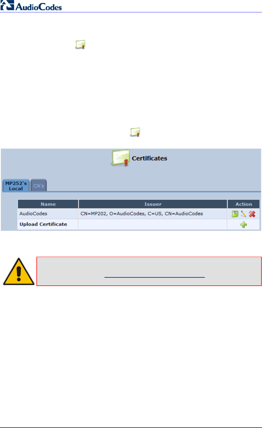
MP252 Multimedia Home Gateway 192 Document #: LTRT-23504
User's Manual
13.3 Securing Remote Management with Certificates
The Certificates icon allows you to configure certificates. When a service provider
implements remote provisioning in which a unique configuration file (per MP252) is placed on
a server located on the WAN, the service provider can ensure that only its deployed MP252
units are able to connect to the HTTP server via HTTPS. This is performed by using a
certification validation process (client-server).
There are two types of certificates:
Self-signed certificates
Certificate Authority (CA) signed certificates
The procedure below describes how to operate with self-signed certificates.
¾ To operate with self-signed certificates:
1. In the 'Advanced' screen, click the icon; the 'Certificates' screen appears.
Figure 13-4: New Certificates Screen
2. Create a self-signed certificate:
Note: You can also create a self-signed certificate using the OpenSSL utility,
downloaded from http://sial.org/howto/openssl/self-signed.
a. Select the MP252’s Local tab.
b. Click the Create Self Signed Certificate button; the 'Create Self Signed X509
Certificate' screen appears.
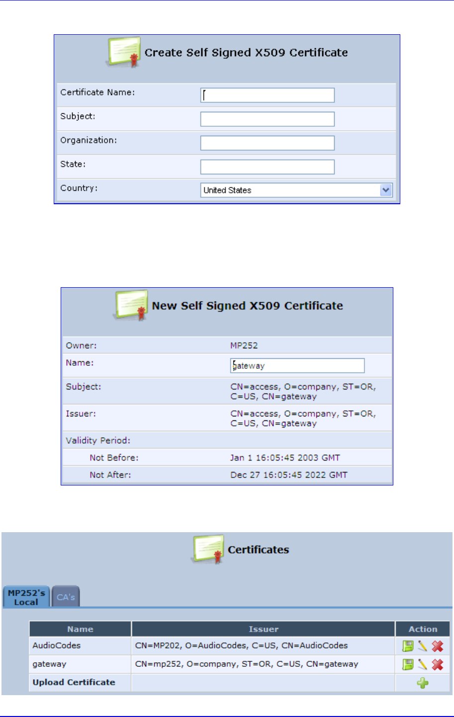
MP252 Multimedia Home Gateway 13. Remote MP252 Management
Version 3.4.0 193 June 2011
Figure 13-5: Create Self Signed X509 Certificate Screen
c. Enter the fields as required, and then click Generate; a message appears notifying
you that MP252 is generating the certificate.
d. After a few moments, click Refresh; the 'New Self Signed X509 Certificate' screen
appears.
Figure 13-6: New Self Signed X509 Certificate Screen
e. Click OK; the new certificate appears listed in the 'Certificates' screen.
Figure 13-7: Newly Created Self-Signed Certificate
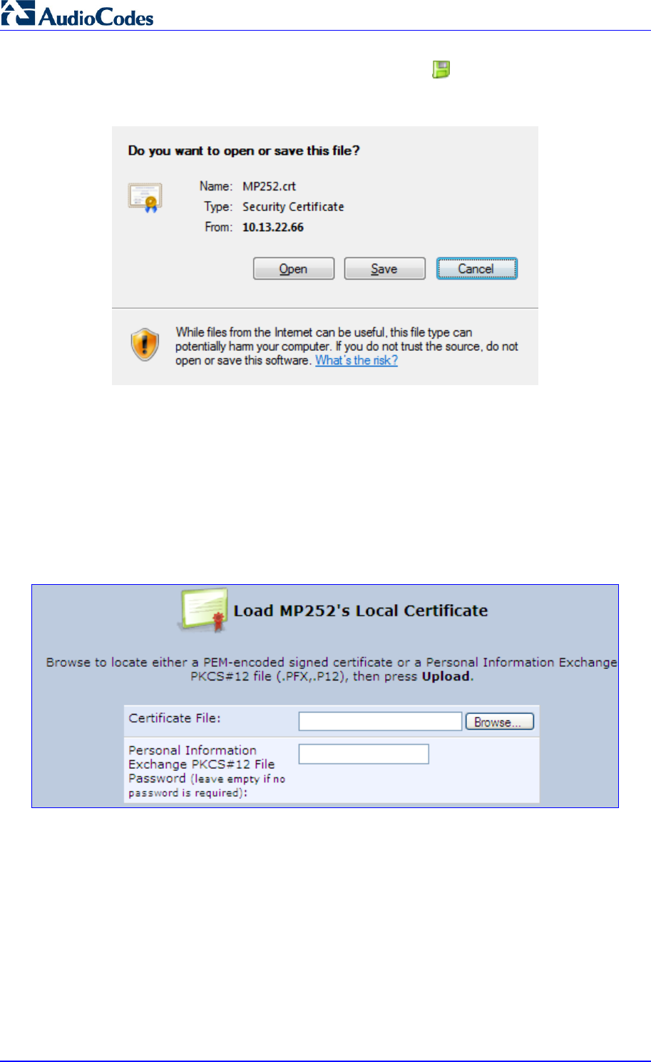
MP252 Multimedia Home Gateway 194 Document #: LTRT-23504
User's Manual
f. In the 'Certificates' screen, click the Download icon corresponding to the new
self-signed certificate that you created; the 'File Download' window appears.
Figure 13-8: File Download Window
g. Click Save, and then browse to the folder to where you want to save the file; the file
is saved as a *.crt file.
3. Configure the Apache server, by configuring the SSLCACertificateFile parameter to
point to the location where the certificate file is located. Since this is a self-signed
certificate, you are also considered the CA.
4. Load the self-signed certificate to MP252:
a. In the 'Certificates' screen, click the Upload Certificate link; the ‘Load MP252’s
Local Certificate’ screen appears.
Figure 13-9: Load MP252’s Local Certificate
b. Click Browse, locate the certification file that you created, and then click Upload to
load the file.
5. Load the CA’s certificate to MP252:
a. Select the CA’s tab; the ‘CA’s’ screen appears.
Figure 13-10: CA's Certificates Page
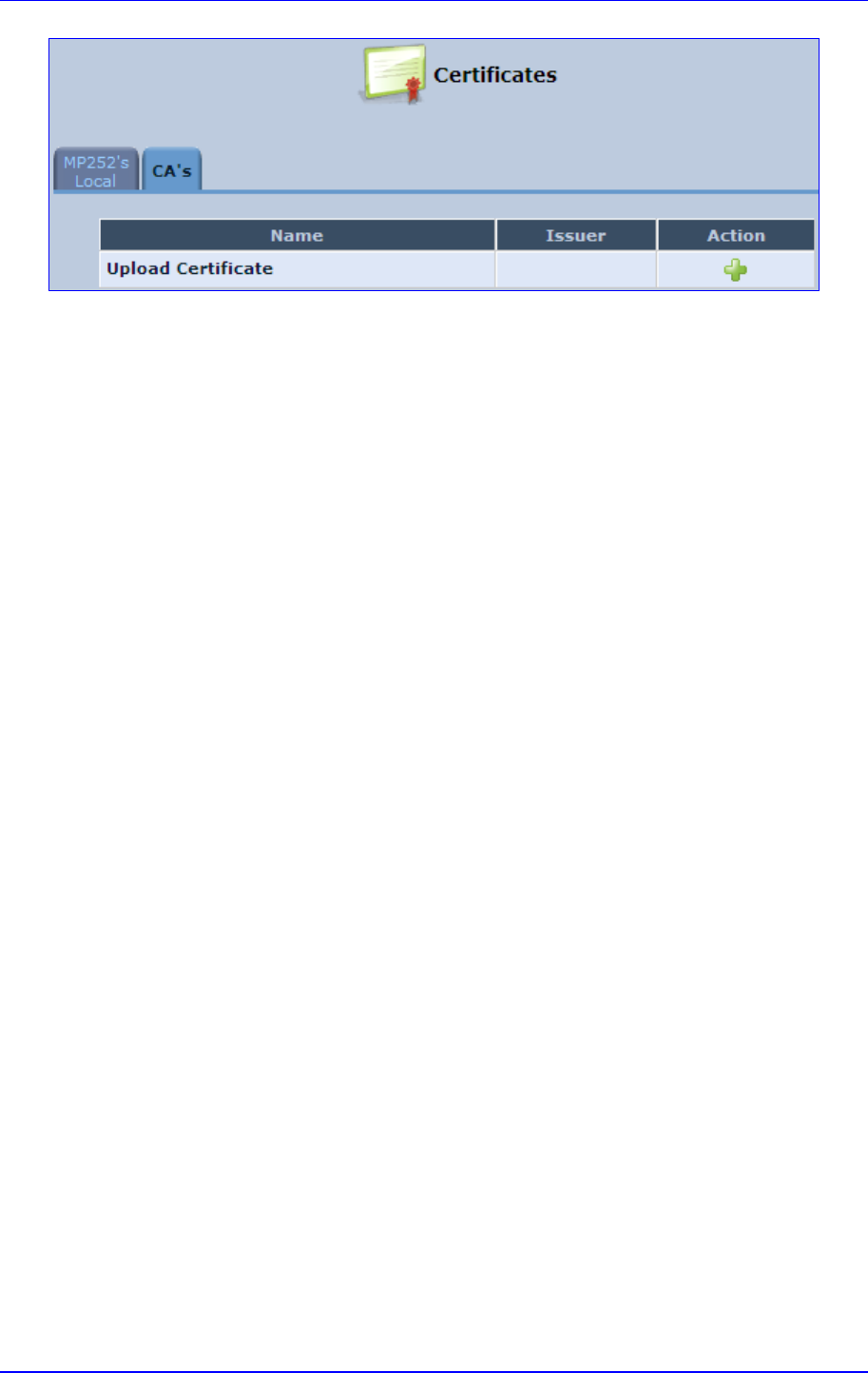
MP252 Multimedia Home Gateway 13. Remote MP252 Management
Version 3.4.0 195 June 2011

MP252 Multimedia Home Gateway 196 Document #: LTRT-23504
User's Manual
b. Click the New icon; the ‘Load CA’s Certificate’ screen appears.
Figure 13-11: Load CA's Certificate Page
c. Click Browse, locate the CA certification file that you created, and then click
Upload to load the file.
6. Configure the Apache server, using the following parameters:
• SSLCACertificateFile: Set the path to the CA’s certificate.
• SSLCertificateFile: Set the path to your signed certificate.
• SSLCertificateKeyFile: Set the path to your private key.

MP252 Multimedia Home Gateway 13. Remote MP252 Management
Version 3.4.0 197 June 2011
13.4 Remote Configuration and Management Interfaces
MP252 supports the following remote configuration and management interfaces:
Web server (GUI) over HTTP/HTTPS
TR-069 and TR-104
SNMP
Syslog
Firmware or configuration file download through HTTP/HTTPS and FTP/TFTP
CLI over Telnet/SSH
The table below lists the possible operations over these different interfaces:
Table 13-5: Operations per Configuration/Management Interface
Operation Web GUI TR-069 SNMP Syslog File D/L CLI
Configuration Update Yes Yes Yes No Yes Yes
Firmware Upgrade Yes Yes Yes No Yes Yes
Status Monitoring Yes Yes Yes No No Yes
Debugging and
Diagnostics Yes No No Yes No Yes
Service providers can choose to combine several management interfaces, for example,
automatic file download for configuration and firmware updates plus SNMP for alarms.
13.4.1 Embedded Web Server
MP252 provides an embedded Web server with a rich Graphical User Interface (GUI). The
Web server can be accessed from the local LAN interface (e.g. by the home user) or from the
WAN interface (e.g. by the service provider support personnel). The Web GUI provides easy
and intuitive configuration of all MP252 parameters (i.e., VoIP, network interfaces, security,
QoS and advanced system settings). In addition, the Web GUI provides status monitoring
pages, diagnostic pages and enabled firmware upgrade.
Typically, service providers do not want to configure each MP252 manually and therefore,
they do not use the Web server in live deployments. However, the Web server is still useful
for:
Trying different configurations in the lab during the integration phases
Creating mass-configuration template files
Debugging special customer problems (by accessing the Web server from the WAN
interface)
Since the Web server allows all configuration and management operations, it is important to
protect it. The following security measures are available:
The Web server is user and password protected. Several users can be defined. A
special user with limited-access (only to the 'Quick Setup' screen) can be defined.
The access to the Web server can be blocked from the WAN and/or LAN interfaces.
Access to the Web server can be limited to specific IP addresses.
Secured HTTP (HTTPS) is supported. It is possible to enable HTTPS-only, if required.
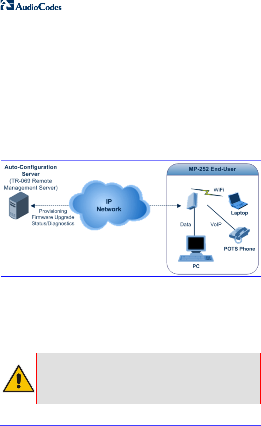
MP252 Multimedia Home Gateway 198 Document #: LTRT-23504
User's Manual
The HTTP and/or HTTPS port can be modified (from the default 80 and 8080).
13.4.2 TR-069 and TR-104 CPE WAN Management Protocol
TR-069 is a WAN management protocol intended for communication between Customer
Premise Equipment (CPE) or residential devices (such as MP252), and an
Auto-Configuration Server (ACS), residing on the service provider's side. It defines a
mechanism that encompasses secure auto configuration of CPE, and also incorporates
other CPE management functions into a common framework. In simpler terms, TR-069 is a
protocol that enables remote server management of theMP252. Such a protocol is useful, for
example, for remotely and securely controlling MP252 by the CPE provider. The standard is
published by the DSL Forum. TR-069 runs over SOAP/HTTP and enables device
configuration, management (including firmware upgrade), and status monitoring. TR-104 is
an extension of TR-069 for VoIP configuration and monitoring.
The TR standards are published by the DSL forum:
TR-069: http://www.broadband-forum.org/technical/download/TR-069.pdf
TR-104: http://www.broadband-forum.org/technical/download/TR-104.pdf
Figure 13-12: TR-069 CPE WAN Management Protocol
The TR-069 protocol allows an ACS to provision a CPE or collection of CPE based on a
variety of criteria. The provisioning mechanism includes specific provisioning parameters
and a general mechanism for adding vendor-specific provisioning capabilities as needed.
The provisioning mechanism allows CPE provisioning at the time of initial connection to the
broadband access network, and the ability to re-provision at any subsequent time. This
includes support for asynchronous ACS-initiated re-provisioning of CPE. TR-069 defines
several Remote Procedure Call (RPC) methods, as well as a large number of parameters,
which may be set or read. Some of these methods and parameters are defined as
mandatory.
Notes:
• MP252 was tested for interoperability with two ACS vendors – Motive and
FriendlyTR69. Working with other ACS types may require specific
interoperability effort.
• The parameter values in the subsequent tables are sample values only
taken from an ACS.

MP252 Multimedia Home Gateway 13. Remote MP252 Management
Version 3.4.0 199 June 2011
13.4.2.1 Configuring MP252 via TR-069 and TR-104
TR-069 allows basic configuration of MP252. The configuration is defined in a hierarchical
tree-like structure according to the TR-069 standard.
13.4.2.1.1 Configuring the WAN Interface
Table 13-6: InternetGatewayDevice.WANDevice.i.WANConnectionDevice.i.WANIPConnection.i
TR-069/TR-104
Parameter Configuration File
Parameter Description
AddressingType mt_cwmp_param_wan_con
n_ip_addressing_type_get/
set
The method used to assign an address to the
WAN side interface of the CPE for this
connection:
“DHCP”
“Static”
ConnectionStatus mt_cwmp_param_wan_con
n_ip_status_get Current status of the connection:
“Unconfigured”
“Connecting”
“Connected”
“PendingDisconnect”
“Disconneting”
“Disconnected”
ConnectionType mt_cwmp_param_wan_con
n_ppp_type_get Specifies the connection type of the
connection instance:
“Unconfigured”
“IP_Routed”
“DHCP_Spoofed”
“PPPoE_Bridged”
“PPPoE_Relay”
“PPTP_Relay”
“L2TP_Relay”
DefaultGateway mt_cwmp_param_wan_con
n_ip_default_gateway_get/
set
The IP address of the default gateway for this
connection. This parameter is configurable
only if the AddressingType is Static.
DNSEnabled mt_cwmp_param_wan_con
n_ip_dns_enabled_get/set Whether or not the device should attempt to
query a DNS server across this connection.
DNSOverrideAllowed mt_cwmp_param_wan_con
n_ip_dnsoverrideallowed_
get/set
Whether or not a manually set, non-empty
DNS address can be overridden by a DNS
entry received from the WAN.
DNSServers mt_cwmp_param_wan_con
n_xxx_dnsservers_get/set(
i)
Comma-separated list of DNS server IP
addresses for this connection. Support for
more than three DNS Servers is optional.
Enable mt_cwmp_param_wan_con
n_xxx_enable_get/set(1) Enables or disables the connection instance.
On creation of a WANIPConnection instance,
it is initially disabled.
ExternalIPAddress mt_cwmp_param_wan_con
n_xxx_externalip_get(i) The external IP address used by NAT for this
connection. This parameter is configurable
only if the AddressingType is Static.

MP252 Multimedia Home Gateway 200 Document #: LTRT-23504
User's Manual
TR-069/TR-104
Parameter Configuration File
Parameter Description
MaxMTUSize mt_cwmp_param_wan_con
n_ip_max_mtu_size_get/se
t( i)
The maximum allowed size of an Ethernet
frame from LAN-side devices.
Name mt_cwmp_param_wan_con
n_xxx_name_get/set(i) User-readable name of this connection.
NATEnabled mt_cwmp_param_wan_con
n_xxx_nat_enabled_get/set
(i )
Indicates if NAT is enabled for this connection.
PortMappingNumberO
f
Entries
- Total number of port mapping entries.
PossibleConnectionTy
pes
- A comma-separated list indicating the types o
f
connections possible for this connection
instance. Each element of the list is an
enumeration of:
“Unconfigured”
“IP_Routed”
“IP_Bridged”
RouteProtocolRx mt_cwmp_param_wan_con
n_xxx_route_protocol_rx_
get/set
Defines the Rx protocol to be used:
“Off”
“RIPv1” (Optional)
“RIPv2” (Optional)
“OSPF” (Optional)
RSIPAvailable mt_cwmp_param_wan_con
n_xxx_rsip_available_get(i) Indicates if Realm-specific IP (RSIP) is
available as a feature on MP252.
ShapingRate - Rate to shape this connection’s egress traffic
to.
If less than or equal to 100, in percentages of
the rate of the highest rate-constrained layer
over which the packet travels on egress. The
rate is limited over the window period
specified by ShapeWindow.
If greater than 100, in bits per second.
A value of -1 indicates no shaping.
SubnetMask lan_host_config_managem
ent_get/set
rg_conf dhcps/ netmask
Subnet mask of the WAN interface. This
parameter is configurable only if the
AddressingType is Static.
SpecVersion “” Currently, 1.0 is the only available version.
Uptime - The time in seconds that this connection has
been up.
13.4.2.1.2 Configuring the LAN Interface
Table 13-7: InternetGatewayDevice.LANDevice.i.LANEthernetInterfaceConfig

MP252 Multimedia Home Gateway 13. Remote MP252 Management
Version 3.4.0 201 June 2011
TR-069/TR-104
Parameter Configuration File
Parameter Description
Enable device_eic_enable_get/set Enables or disables this interface.
MACAddress device_mac_address_get The physical address of the interface.
MaxBitRate device_max_bit_rate_get The maximum upstream and downstream
bit rate available for this connection:
“10”
“100”
“1000”
“Auto”
Status device_status_get The status of the interface:
“Up”
“NoLink”
“Error”
“Disabled”

MP252 Multimedia Home Gateway 202 Document #: LTRT-23504
User's Manual
Table 13-8: InternetGatewayDevice.LANDevice.i.LANHostConfigManagement
TR-069/TR-104
Parameter Configuration File
Parameter Description
AllowedMACAddres
ses
allowed_mac_addresses_g
et/set Represents a comma-separated list of
hardware addresses that are allowed to
connect to this connection if
MACAddressControlEnabled is 1 for a
given interface.
DHCPLeaseTime dhcp_lease_time_get/set Specifies the lease time in seconds of client
assigned addresses. A value of -1
indicates an infinite lease.
DHCPRelay dhcp_relay_get/set Determines if the DHCP server performs
the role of a server (0) or a relay (1) on the
LAN interface.
DHCPServerEnable lan_host_config_managem
ent_get/set
rg_conf dhcps/enable
Enables or disables the DHCP server on
the LAN interface.
DNSServers dhcps_dns_servers_get/se
t Comma-separated list of DNS servers
offered to DHCP clients. Support for more
than three DNS Servers is optional.
DomainName domain_name_get/set Sets the domain name for clients on the
LAN interface.
IPRouters ip_routers_get/set Comma-separated list of IP addresses of
routers on this subnet. Also known as
default gateway. Support for more than one
Router address is optional.
MaxAddress lan_host_config_managem
ent_get/set
rg_conf dhcps/end_ip
Specifies the last address in the pool to be
assigned by the DHCP server on the LAN
interface.
MinAddress lan_host_config_managem
ent_get/set
rg_conf dhcps/start_ip
Specifies the first address in the pool to be
assigned by the DHCP server on the LAN
interface.
SubnetMask lan_host_config_managem
ent_get/set
rg_conf dhcps/ netmask
Specifies the client’s network subnet mask.

MP252 Multimedia Home Gateway 13. Remote MP252 Management
Version 3.4.0 203 June 2011
13.4.2.1.3 Configuring VoIP via TR-104
Table 13-9: InternetGatewayDevice.Services.VoiceService.i.Capabilities
TR-069/TR-104
Parameter Configuration File
Parameter Description
ButtonMap - Support for a configurable button map. A true
value indicates support for a configurable
button map via the
VoiceService.{i}.VoiceProfile.{i}.ButtonMap
object.
DSCPCoupled - A true value indicates that the CPE is
constrained such that transmitted call control
packets use the same DSCP marking as
transmitted RTP packets.
If the value is true, the CPE must not support
the DSCPMark parameter for call control.
EthernetTaggingCou
pled
- A true value indicates that the CPE is
constrained such that transmitted call control
packets use the same Ethernet tagging (VLAN
ID Ethernet Priority) as transmitted RTP
packets.
If the value is true, the CPE must not support
the VLANIDMark or EthernetPriorityMark
parameters within a call control object (e.g.,
SIP, MGCP, or H323).
FaxPassThrough - Support for fax pass-through. A true value
indicates support for the parameter
VoiceService.{i}.VoiceProfile.{i}.FaxPassThro
ugh. (True if
voip/audio/fax/fax_transport_mode equals
Bypass)
FaxT38 - Support for T.38 fax. A true value indicates
support for the object
VoiceService.{i}.VoiceProfile.{i}.FaxT38.
MaxLineCount voip/num_of_fxs_lines Maximum number of lines supported across all
profiles.
MaxProfileCount - Maximum number of distinct voice profiles
supported.
MaxSessionCount - Maximum number of voice sessions supported
across all lines and profiles. (This might differ
from MaxLineCount if each line can support
more than one session for CPE provided
conference calling. This value can be less than
the product of MaxLineCount and
MaxSessionsPerLine.)
MaxSessionsPerLin
e
- Maximum number of voice sessions supported
for any given line across all profiles. A value
greater than one indicates support for CPE
provided conference calling.

MP252 Multimedia Home Gateway 204 Document #: LTRT-23504
User's Manual
TR-069/TR-104
Parameter Configuration File
Parameter Description
ModemPassThrough - Support for modem pass-through. A true value
indicates support for the parameter
VoiceService.{i}.VoiceProfile.{i}.ModemPassT
hrough.
NumberingPlan - Support for a configurable numbering plan. A
true value indicates support for a configurable
numbering plan via the
VoiceService.{i}.VoiceProfile.{i}.NumberingPla
n object.
PSTNSoftSwitchOve
r
- A true value indicates MP252 is capable of
supporting the PSO_Activate Facility Action,
which allows a call to be switched to a PSTN
FXO.
Note: Currently, this parameter is not
supported.
Regions pkg\mgt\lib\mgt_regiona
l_settings.c
slic_dsp_general_and_r
egional_settings_param
s_array
Comma-separated list of geographic regions
supported by MP252. Each item in the list
must be an alpha-2 (two-character alphabetic)
country code as specified by ISO 3166.
An empty list indicates that MP252 does not
support region-based customization.
Note: This format is currently not supported.
RingGeneration - Support for ring generation. A true value
indicates support for control of ring generation
via the
VoiceService.{i}.VoiceProfile.{i}.Line.{i}.Ringer
object.
A true value also indicates that the
RingDescriptionsEditable,
PatternBasedRingGeneration and
FileBasedRingGeneration parameters in this
object are present.
RTCP - Support for RTCP.
RTPRedundancy - Support for RTP payload redundancy as
defined in RFC 2198. A true value indicates
support for
VoiceService.{i}.VoiceProfile.{i}.RTP.Redunda
ncy.
SignalingProtocols voip/signalling/protocol Signal protocol:
“SIP”
“MGCP”
Each entry can be appended with a version
indicator in the form “/X.Y”. For example:
“SIP/2.0”.
Note: Only one protocol is supported at a time.
SRTP - Support for SRTP.
Note: Currently, SRTP is not supported.

MP252 Multimedia Home Gateway 13. Remote MP252 Management
Version 3.4.0 205 June 2011
TR-069/TR-104
Parameter Configuration File
Parameter Description
ToneGeneration - Support for tone generation. A true value
indicates support for the object
VoiceService.{i}.VoiceProfile.{i}.Tone.
A true value also indicates that the
ToneDescriptionsEditable,
PatternBasedToneGeneration and
FileBasedToneGeneration parameters in this
object are present.
VoicePortTests - Support for remotely accessible voice-port
tests. A true value indicates support for the
VoiceService.{i}.PhyInterface.{i}.Tests object.
Table 13-10: InternetGatewayDevice.Services.VoiceService.i.Capabilities.Codecs
TR-069/TR-104
Parameter Configuration File
Parameter Description
Codec voip/codec/i/name Identifier of the type of codec.
EntryID voip/codec/i/ Unique identifier for each entry in the table.
PacketizationPeriod voip/codec/i/ptime Comma-separated list of supported
packetization periods (in milliseconds), or
continuous ranges of packetization periods.
Ranges are indicated as a hyphen-separated
pair of unsigned integers.
For example:
“20” indicates a single discrete value.
“10, 20, 30” indicates a set of discrete
values.
“5-40” indicates a continuous inclusive
range.
“5-10, 20, 30” indicates a continuous
range in addition to a set of discrete
values.
A range must only be indicated if all values
within the range are supported.
Note: Currently, only a single ptime per
codec is supported.

MP252 Multimedia Home Gateway 206 Document #: LTRT-23504
User's Manual
Table 13-11: InternetGatewayDevice.Services.VoiceService.i.VoiceProfile
TR-069/TR-104
Parameter Configuration File
Parameter Description
DTMFMethod voip/out_of_band_dtmf Method by which DTMF digits must be
passed:
“InBand”
“RFC2833”
“SIPInfo
Enable - Enables or disables all lines in this profile, or
places it into a quiescent state:
“Disabled”
“Quiescent”
“Enabled”
On creation, a profile must be in the Disabled
state.
In the Quiescent state, in-progress sessions
remain intact, but no new sessions are
allowed. Support for the Quiescent state in a
MP252 is optional. If this parameter is set to
“Quiescent” in a MP252 that does not support
the Quiescent state, it must treat it the same
as the Disabled state.
Name - String to easily identify the profile instance.
Note: Currently, this is not supported.
NumberOfLines voip/num_of_fxs_lines Number of instances of Line within this
VoiceProfile.
Table 13-12: InternetGatewayDevice.Services.VoiceService.i.VoiceProfile.i.SIP
TR-069/TR-104
Parameter Configuration File
Parameter Description
OutboundProxy voip/
signalling/sip/sip_outbou
nd_proxy/addr
Host name or IP address of the outbound
proxy. If a non-empty value is specified, the
SIP endpoint must send all SIP traffic
(requests and responses) to the host
indicated by this parameter and the port
indicated by the OutboundProxyPort
parameter. This must be done regardless of
the routes discovered using normal SIP
operations, including use of Route headers
initialized from Service-Route and
Record-Route headers previously received.
The OutboundProxy value is not used to
generate the URI placed into the Route
header of any requests.

MP252 Multimedia Home Gateway 13. Remote MP252 Management
Version 3.4.0 207 June 2011
TR-069/TR-104
Parameter Configuration File
Parameter Description
OutboundProxyPort voip/
signalling/sip/sip_outbou
nd_proxy/proxy
Destination port for connecting to the
outbound proxy. This parameter must be
ignored unless the value of the
OutboundProxy parameter in this object is
non-empty.
ProxyServer voip/signalling/sip/proxy_
address
or
voip/signalling/sip/sip_re
gistrar/addr
Host name or IP address of the SIP proxy
server.
ProxyServerPort voip/signalling/sip/proxy_
port
or
voip/signalling/sip/sip_re
gistrar/port
Destination port for connecting to the SIP
server.
ProxyServerTranspo
rt
voip/signalling/sip/transp
ort_protocol Transport protocol for connecting to the SIP
server. Must be chosen from among the
transports supported.
RegisterExpires voip/signalling/sip/proxy_
timeout Register request Expires header value (in
seconds).
RegistrarServerTran
sport
voip/signalling/sip/transp
ort_protocol Transport protocol for connecting to the SIP
server. Must be chosen from among the
transports supported.
UserAgentPort voip/signalling/sip/port Port for incoming call control signaling.
UserAgentTransport voip/signalling/sip/transp
ort_protocol Transport protocol for incoming call control
signaling.
13.4.2.1.4 Upgrading Firmware via TR-069
TR-069 contains a built-in mechanism for MP252 firmware upgrade.
13.4.2.2 Monitoring MP252 Status via TR-069 and TR-104
The service provider can monitor the status of MP252 via TR-069 and TR-104.
13.4.2.2.1 Device Information
Table 13-13: InternetGatewayDevice.DeviceInfo
TR-069/TR-104
Parameter Configuration File
Parameter Description
Description manufacturer/description A full description of MP252 (string).
DeviceLog “” Vendor-specific log(s).
HardwareVersion Manufacturer/hardware/v
ersion A string identifying the particular MP252
model and version.

MP252 Multimedia Home Gateway 208 Document #: LTRT-23504
User's Manual
TR-069/TR-104
Parameter Configuration File
Parameter Description
Manufacturer manufacturer/vendor_na
me A string identifying the manufacturer of
MP252, i.e., AudioCodes.
ManufacturerOUI manufacturer/vendor_oui Organizationally unique identifier of the
device manufacturer. Represented as a six
hexadecimal-digit value using all upper-case
letters and including any leading zeros.
ModelName manufacturer/model_num
ber A string identifying the model name of
MP252.
ProductClass manufacturer/product_cla
ss Identifier of the class of product for which the
serial number applies. That is, for a given
manufacturer, this parameter is used to
identify the product or class of product over
which the SerialNumber parameter is unique.
ProvisioningCode cwmp/provisioning_code Identifier of the primary service provider and
other provisioning information, which may be
used by the Server to determine service
provider-specific customization and
provisioning parameters.
If non-empty, this argument must be in the
form of a hierarchical descriptor with one or
more nodes specified. Each node in the
hierarchy is represented as a 4-character
sub-string, containing only numerals or
upper-case letters. If there is more than one
node indicated, each node is separated by a
"." (dot). For example, “TLCO” and
“TLCO.GRP2”.
SerialNumber Manufacturer/hardware/s
erial_num Serial number of MP252.
SoftwareVersion system/external_version A string identifying the software version
currently installed in MP252.
To allow version comparisons, this element
must be in the form of dot-delimited integers,
where each successive integer represents a
more minor category of variation. For
example, 3.0.21 where the components
mean Major.Minor.Build.
UpTime - Time in seconds since MP252 was last reset.

MP252 Multimedia Home Gateway 13. Remote MP252 Management
Version 3.4.0 209 June 2011
13.4.2.2.2 WAN Status
Table 13-14: InternetGatewayDevice.WANDevice.i.WANConnectionDevice.i.
WANIPConnection.i.Stats
TR-069/TR-104
Parameter Configuration File
Parameter Description
EthernetBytesRecei
ved
mt_cwmp_param_wan_co
nn_ip_stats_get
(STAT_RX_BYTES)
Total number of bytes received over all
connections within the same
WANConnectionDevice that share a common
MAC address since MP252 was last reset.
EthernetBytesSent mt_cwmp_param_wan_co
nn_ppp_stats_get (
STAT_TX_BYTES)
Total number of bytes sent over all
connections within the same
WANConnectionDevice that share a common
MAC address since MP252 was last reset.
EthernetPacketsRec
eived
mt_cwmp_param_wan_co
nn_ppp_stats_get
( STAT_RX_PACKETS)
Total number of Ethernet packets received
over all connections within the same
WANConnectionDevice that share a common
MAC address since MP252 was last reset.
EthernetPacketsSen
t
mt_cwmp_param_wan_co
nn_ppp_stats_get Total number of Ethernet packets sent over
all connections within the same
WANConnectionDevice that share a common
MAC address since MP252 was last reset.
13.4.2.2.3 LAN Status
Table 13-15: InternetGatewayDevice.LANDevice.i.LANEthernetInterfaceConfig.i.Stats
TR-069/TR-104
Parameter Configuration File
Parameter Description
BytesReceived mt_voip_get_state (line,
state) Total number of bytes received over the
interface since MP252 was last reset.
BytesSent mt_voip_get_state(line,
state) Total number of bytes sent over the interface
since MP252 was last reset.
PacketsReceived mt_voip_get_state(line,
state) Total number of packets received over the
interface since MP252 was last reset.
PacketsSent mt_voip_get_state(line,
state) Total number of packets sent over the
interface since MP252 was last reset.

MP252 Multimedia Home Gateway 210 Document #: LTRT-23504
User's Manual
13.4.2.2.4 VoIP Status via TR-104
Table 13-16: InternetGatewayDevice.Services.VoiceService.i.VoiceProfile.i.Line.i.Stats
TR-069/TR-104
Parameter Configuration File
Parameter Description
ResetStatistics - When set to one, it resets the statistics for
this voice line. Always False when read.
PacketsSent mt_voip_get_state(line,
state) Total number of RTP packets sent for this
line.
PacketsReceived mt_voip_get_state(line,
state) Total number of RTP packets received for
this line.
BytesSent mt_voip_get_state(line,
state) Total number of RTP payload bytes sent for
this line.
BytesReceived mt_voip_get_state(line,
state) Total number of RTP payload bytes received
for this line.
PacketsLost mt_voip_get_state(line,
state) Total number of RTP packets that have been
lost for this line.
Overruns - Total number of times the receive jitter buffer
has overrun for this line.
Underruns - Total number of times the receive jitter buffer
has underrun for this line.
IncomingCallsReceive
d
- Total incoming calls received.
IncomingCallsAnswere
d
- Total incoming calls answered by the local
user.
IncomingCallsConnect
ed
- Total incoming calls that successfully
completed call setup signaling.
IncomingCallsFailed - Total incoming calls that failed to successfully
complete call setup signaling.
OutgoingCallsAttempt
ed
- Total outgoing calls attempted.
OutgoingCallsAnswere
d
- Total outgoing calls answered by the called
party.
OutgoingCallsConnect
ed
- Total outgoing calls that successfully
completed call setup signaling.
OutgoingCallsFailed - Total outgoing calls that failed to successfully
complete call setup signaling.
CallsDropped - Total calls that were successfully connected
(incoming or outgoing), but dropped
unexpectedly while in progress without
explicit user termination.
TotalCallTime - Cumulative call duration (in seconds).
ServerDownTime - The number of seconds MP252 is unable to
maintain a connection to the server. Applies
only to SIP.

MP252 Multimedia Home Gateway 13. Remote MP252 Management
Version 3.4.0 211 June 2011
TR-069/TR-104
Parameter Configuration File
Parameter Description
ReceivePacketLossRat
e
mt_voip_get_state(line,
state) Current receive packet loss rate (in
percentage).
FarEndPacketLossRat
e
- Current far-end receive packet lost rate (in
percentage).
ReceiveInterarrivalJitte
r
- Current receive interarrival jitter (in
microseconds).
FarEndInterarrivalJitte
r
- Current Interarrival jitter (in microseconds) as
reported from the far-end device via RTCP.
RoundTripDelay mt_voip_get_state Current round-trip delay (in microseconds).
AverageReceiveInterar
rivalJitter
- Average receive interarrival jitter (in
microseconds) since the beginning of the
current call.
AverageFarEndInterarr
ivalJitter
- Average far-end interarrival jitter (in
microseconds) since the beginning of the
current call.
AverageRoundTripDel
ay
- Average round-trip delay (in microseconds)
since the beginning of the current call. This is
the average of the RoundTripDelay statistics
accumulated each time the delay is
calculated.
13.4.2.3 Security Concerns and Measures
The CPE WAN Management Protocol is designed to allow a high degree of security in the
interactions that use it. The CPE WAN Management Protocol is designed to prevent
tampering with the transactions that take place between a CPE and ACS, provide
confidentiality for these transactions, and allow various levels of authentication.
The following security mechanisms are incorporated in this protocol:
The protocol supports the use of SSL/TLS for communications transport between CPE
and ACS. This provides transaction confidentiality, data integrity, and allows
certificate-based authentication between the CPE and ACS.
The HTTP layer provides an alternative means of CPE authentication based on shared
secrets.
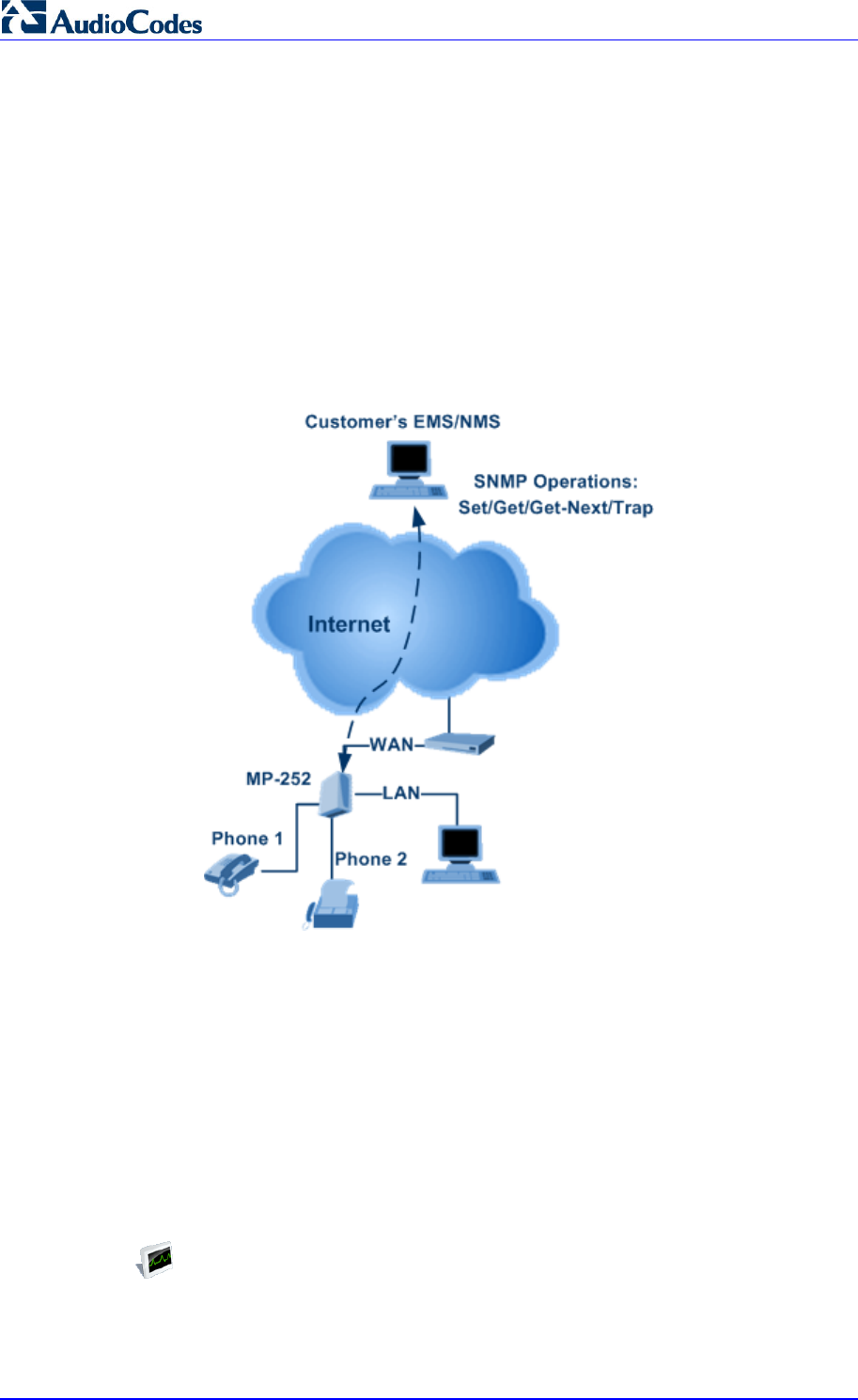
MP252 Multimedia Home Gateway 212 Document #: LTRT-23504
User's Manual
13.4.3 SNMP
Simple Network Management Protocol (SNMP) is used in network management systems to
configure and monitor network-attached devices. SNMP is an IETF standard defined by RFC
1157, 1441 and additional RFCs for specific Management Information Base (MIBs).
MP252 contains an embedded SNMP agent and supports SNMPv1, SNMPv2 and partially
supports SNMPv3. For monitoring of the network interfaces, the standard SNMP MIB-II
(RFC 1213) is supported. For more options, a proprietary MIB, AC-MP20X-MIB includes the
following sections:
acMP20xConfig: for changing MP252's configuration
acMP20xStatus: for monitoring MP252's status
The figure below shows the SNMP network architecture:
Figure 13-13: SNMP Network Architecture
13.4.3.1 Enabling SNMP in the Web Interface
Simple Network Management Protocol (SNMP) enables Network Management Systems
(NMSs) to remotely configure and monitor your MP252. Your ISP may use SNMP to identify
and resolve technical problems. Technical information regarding the properties of MP252's
SNMP agent should be provided by your ISP.
The procedure below describes how to configure the SNMP agent embedded on
the MP252.
¾ To configure MP252's SNMP agent:
1. In the 'Advanced' screen, click the Simple Network Management Protocol (SNMP)
icon; the 'Simple Network Management Protocol (SNMP)' screen appears.
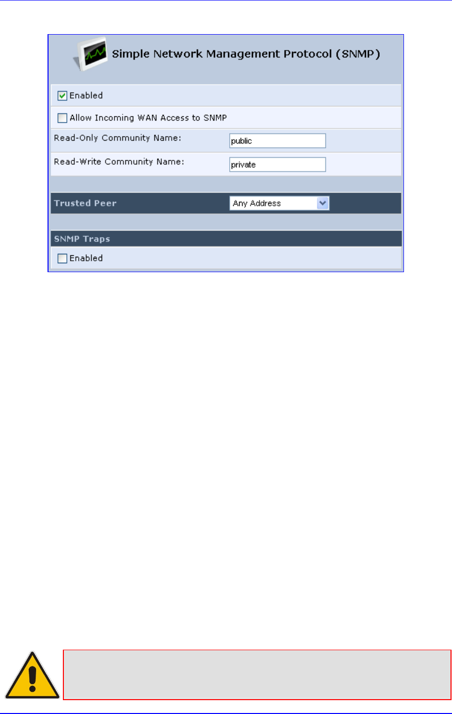
MP252 Multimedia Home Gateway 13. Remote MP252 Management
Version 3.4.0 213 June 2011
Figure 13-14: Simple Network Management Protocol (SNMP) Screen
2. Select the 'Enabled' check box to enable SNMP.
3. Select the ‘Allow Incoming WAN Access to SNMP’ check box to allow access to
MP252's SNMP agent over the Internet.
4. In the ‘Read-Only Community Names’ and ‘Read-Write Community Names’
fields, enter the SNMP community strings. These strings are passwords used in SNMP
messages between the management system and MP252. A read-only community
allows the manager to monitor MP252. A read-write community allows the manager to
monitor and configure MP252.
5. From the ‘Trusted Pair’ drop-down list, enter the IP address, or subnet of addresses that
identify which remote management stations are allowed to perform SNMP operations
on MP252.
6. Under the SNMP Traps group, select the ‘Enabled’ check box to allow MP252 to send
messages (traps) to a remote management station to notify the manager about the
occurrence of important events or serious conditions.
• Version: SNMP version - SNMP v1 or SNMP v2c traps.
• Destination: remote management station's IP address.
• Community: community name that is associated with the trap messages.
7. Click OK to save your settings.
13.4.3.2 Configuring MP252 via SNMP
The acMP20xConfig MIB section is structured in a similar hierarchy as MP252's Web GUI.
Each parameter in the MIB has a matching parameter in the Web GUI and a matching
parameter in the gateway’s configuration file. The MIB file defines the valid range and the
default value for each parameter. Typically, the customer integrates the MP20x MIB into the
customer's Network Management System (NMS) to automate the configuration process.
Note: A special MIB object is defined to allow MP252 firmware upgrade triggered by
SNMP. The object acMP20xRemoteUpdate triggers a remote upgrade from the
SNMP-configured URL.
MP252 Multimedia Home Gateway 214 Document #: LTRT-23504
User's Manual
13.4.3.3 Status Monitoring of System and Network Interfaces via SNMP
SMNP can be used to monitor the status of MP252. Status monitoring of the system and
network interfaces can be done via the standard MIB-II
(iso(1).org(3).dod(6).internet(1).mgmt(2).mib-2(1)). The following table shows some of the
information elements available via MIB-II:
Table 13-17: Table 3-13: Information Elements Available via MIB-II
Section Available Information
system Description
Version Information
Up-time
interfaces Information per network interface:
Description
Type
Speed
MAC address
Traffic statistics
Errors
ip Assigned IP addresses and IP-related parameters
icmp, udp, tcp Transport-protocol specific statistical information
ifMIB Information about network interfaces per RFC 2233
13.4.3.4 Security Concerns and Measures
Since SNMP allows write-access to configuration parameters, it is important to protect this
interface. The following security measures are available:
A community string (password) can be defined for read-only access and for read/write
access.
It is possible to limit access to SNMP to a trusted peer (single IP address or a range of
addresses).
SNMPv3 provides an significant security improvement over SNMPv1/2. Version 2.8.0
will support SNMPv3 and will allow the service provider to configure SNMPv3 security
parameters.
SNMP traffic can be allowed over an IPSec secured connection – check availability with
AudioCodes.

MP252 Multimedia Home Gateway 13. Remote MP252 Management
Version 3.4.0 215 June 2011
13.4.4 Syslog
Syslog is a standard protocol for reporting and logging of messages over IP network and is
defined by RFC 3164. MP252 enables the service provider to configure a Syslog server and
a severity level above which errors are sent to the server. Typically, only error-level
messages should be sent to the Syslog server (in order not to flood it with irrelevant
debug-level information). For debugging, it is possible to temporarily allow logging for
debug-level messages (e.g. for SIP messages).
Many free Syslog servers exist, including Kiwi Syslog Daemon' (http://www.kiwisyslog.co'm
http://www.kiwisyslog.com).
Note: Since Syslog is used only to output messages from MP252, it does not contain
any security concerns.
13.4.5 Automatic File Download
A practical, straight-forward and easy to implement method for mass configuration and
firmware update is automatic file download from a remote file server (via HTTP, FTP, or
TFTP). This method is used by many service providers.
13.4.5.1 Firmware File Download
MP252's firmware files contain information about the target product type and the firmware
version information.
13.4.5.2 Configuration File Download
MP252 supports two configuration file formats, a *.conf file and an *.ini file. Both files define
the same parameters, but in a different format; the *.conf file has a hierarchical tree-like
structure and the *.ini file is "flat" (defining the full path for each parameter).
As with the firmware file, the configuration file can be “pushed” to MP252 via the Web server
or “pulled” by MP252 from a remote server. This section refers only to the second option.
When MP252 downloads a file from a remote server, it performs the following actions:
Decrypts the file, if it is encrypted.
Checks that the file version is later than the current configuration file version (if it is not
later, the new configuration is not used).
Checks the software version with which the configuration file was created (if the file was
created with a later software version, it is not used).

MP252 Multimedia Home Gateway 216 Document #: LTRT-23504
User's Manual
Merges the configuration file with the current configuration:
• Parameters that appear in the new file are modified or added
• Parameters that do not appear in the new file remain in their existing value
Notes:
• It is recommended that the configuration file (that is downloaded from the
network), contains only the small subset of parameters that the service
provider needs to update remotely.
• To create the configuration file, it is recommended to use a MP252 that is
restored to factory settings, modify the required parameters using the Web
GUI, and then upload the configuration file from MP252 with the option to
get only the modified configuration fields enabled.
13.4.5.3 Security Concerns and Measures
The main security hazard in automatic file download is that a hacker can force MP252 to
download a file from the hacker's server instead of the service provider’s legitimate server.
Another concern is exposing information such as the SIP proxy IP address and user and
password information in the configuration file (if the hacker is sniffing the network).
The following security measures are available to prevent this:
The configuration file can be encrypted using 3DES with pre-configured key. This
prevents the user from learning the format of the file and obtaining information from it.
HTTPS can be used to further encrypt the transport.
HTTPS certificates can be used to allow MP252 to authenticate the server and also to
prevent the user from acquiring the file from the server.
13.4.6 Telnet CLI
MP252 features a Command Line Interface (CLI) over Telnet. The CLI enables the service
provider to manage MP252 (e.g. reboot, force a firmware upgrade), to obtain information
about the status of the device (e.g. VoIP calls, network interfaces, version information), to
change the configuration and to perform different debugging tasks (e.g. enable debug
logging, enable packet recording).
Typically, the CLI interface is only used for debugging and diagnostics, since it does not
allow mass configuration and monitoring.
Since the CLI allows all configuration and management operations, it is important to protect
it. The following security measures are available:
The CLI is user and password protected (same as the Web).
Telnet access can be blocked from the WAN and/or LAN interfaces.
It is possible to limit Telnet access to specific IP addresses.
Future versions will support SSH.
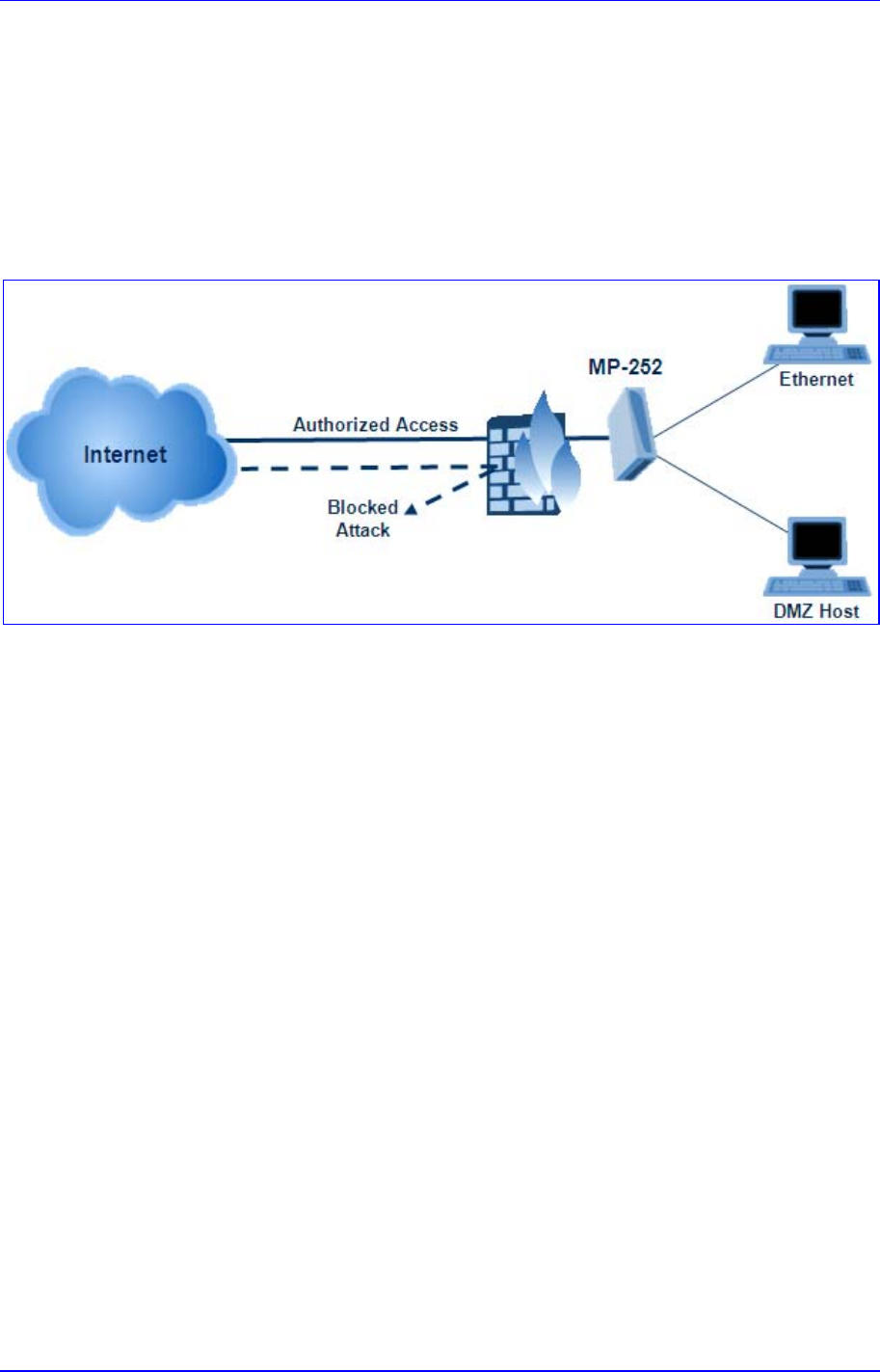
Version 3.4.0 217 July 2011
MP252 Multimedia Home Gateway 14. Security
14 Security
MP252's security suite includes comprehensive and robust security services: Stateful Packet
Inspection Firewall, user authentication protocols and password protection mechanisms.
These features together allow users to connect their computers to the Internet and
simultaneously be protected from the security threats of the Internet.
The firewall, which is the cornerstone of your MP252's security suite, has been exclusively
tailored to the needs of the residential/office user and has been pre-configured to provide
optimum security.
Figure 14-1: Firewall in Action
MP252 firewall provides both the security and flexibility that home and office users seek. It
provides a managed, professional level of network security while enabling the safe use of
interactive applications, such as Internet gaming and video-conferencing.
Additional features, including surfing restrictions and access control, can also be easily
configured locally by the user through a user-friendly Web-based interface, or remotely by a
service provider.
MP252 firewall supports advanced filtering, designed to allow comprehensive control over
the firewall's behavior. You can define specific input and output rules, control the order of
logically similar sets of rules and make a distinction between rules that apply to WAN and
LAN network devices.
The Web-based management screens in the Security section feature the following:
The 'General' screen allows you to choose the security level for the firewall (see'
General Security Level Settings' on page 218).
The 'Access Control' screen can be used to restrict access from the home network to
the Internet (see 'Local Servers (Port Forwarding)' on page 221).
The 'Port Forwarding' screen can be used to enable access from the Internet to
specified services provided by computers in the home network and special Internet
applications (see 'Port Forwarding' on page 221).
The 'DMZ Host' screen allows you to configure a LAN host to receive all traffic arriving at
your MP252, which does not belong to a known session (see' Port Triggering' on page
227).
The 'Port Triggering' screen allows you to define port triggering entries, to dynamically
open the firewall for some protocols or ports. (see 'Remote Administration' on page
253).
The 'Website Restrictions' allows you to block LAN access to a certain host or web site
on the Internet (see 'Website Restrictions' on page 229).
'Advanced Filtering' allows you to implicitly control the firewall setting and rules (see
'Advanced Filtering' on page 236).
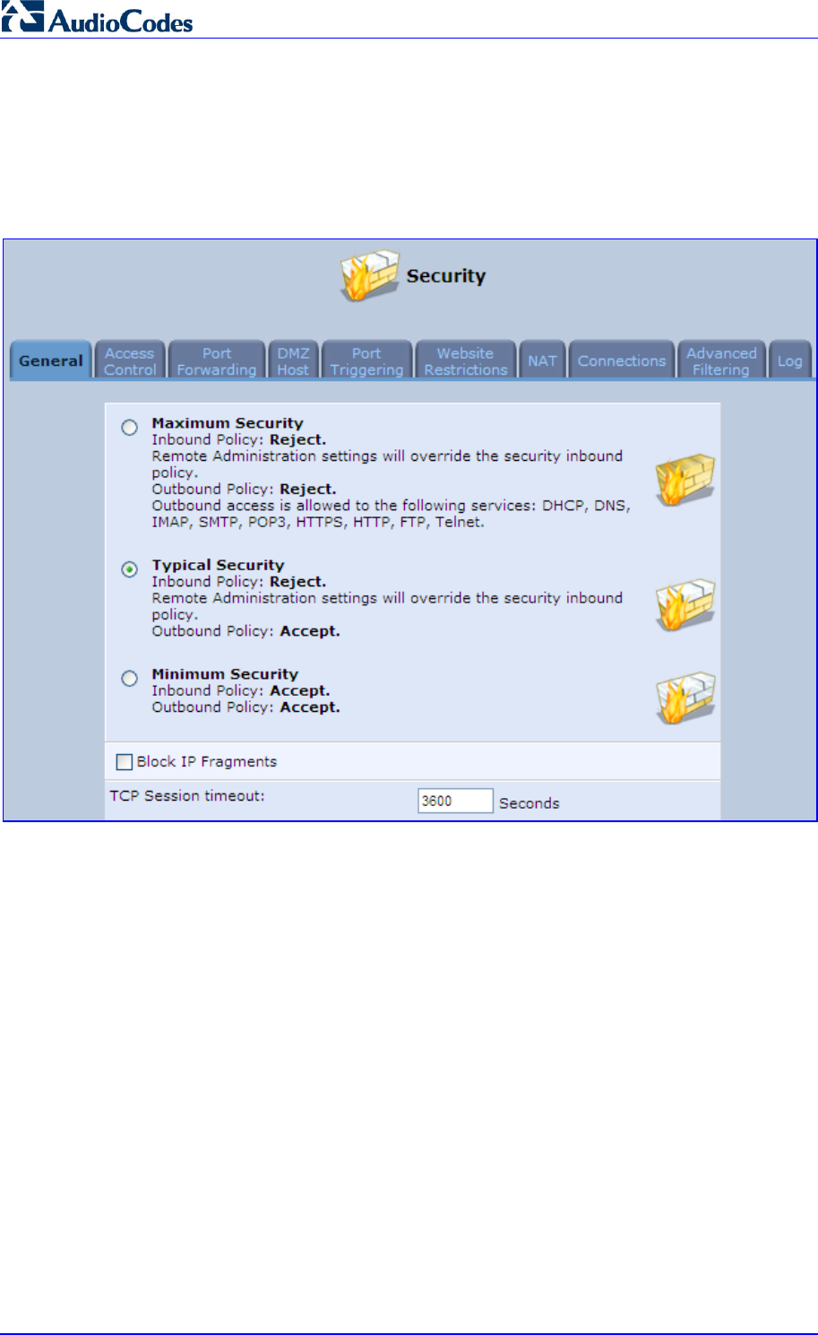
MP252 Multimedia Home Gateway 218 Document #: LTRT-23504
User's Manual
'Security Log' allows you to view and configure the firewall Log (see Security Log).
14.1 General Security Level Settings
Use the 'Security Settings' screen to configure the MP252's basic security settings.
Figure 14-2: General Security Level Settings
The firewall regulates the flow of data between the home network and the Internet. Both
incoming and outgoing data are inspected and then either accepted (allowed to pass through
MP252) or rejected (barred from passing through MP252) according to a flexible and
configurable set of rules. These rules are designed to prevent unwanted intrusions from the
outside, while allowing home users access to the Internet services that they require.
The firewall rules specify what types of services available on the Internet may be accessed
from the home network and what types of services available in the home network may be
accessed from the Internet. Each request for a service that the firewall receives, whether
originating in the Internet or from a computer in the home network, is checked against the set
of firewall rules to determine whether the request should be allowed to pass through the
firewall. If the request is permitted to pass, then all subsequent data associated with this
request (a "session") are also allowed to pass, regardless of its direction.
For example, when you point your Web browser to a Web page on the Internet, a request is
sent out to the Internet for this page. When the request reaches MP252, the firewall identifies
the request type and origin--HTTP and a specific PC in your home network, in this case.
Unless you have configured access control to block requests of this type from this computer,
the firewall allows this request to pass out onto the Internet (see 'WAN PPPoE' on page 173
for more on setting access controls). When the Web page is returned from the Web server
the firewall associates it with this session and allows it to pass, regardless of whether HTTP
access from the Internet to the home network is blocked or permitted.

MP252 Multimedia Home Gateway 14. Security
Version 3.4.0 219 June 2011
Note that it is the origin of the request, not subsequent responses to this request, that
determines whether a session can be established or not.
You can choose from among three pre-defined security levels for MP252: Minimum, Typical,
and Maximum (the default setting). The table below summarizes the behavior of MP252 for
each of the three security levels.
Table 14-1: Behavior for the Three Security Levels
Security Level Requests Originating
in the WAN
(Incoming Traffic)
Requests
Originating
in the LAN
(Outgoing Traffic)
Maximum
Security
(Default)
Blocked: No access to home network
from Internet, except as configured in the
Local Servers, DMZ host and Remote
Access screens
Limited: Only commonly- used services,
such as Web- browsing and e-mail, are
permitted
Typical Security Blocked: No access to home network
from Internet, except as configured in the
Local Servers, DMZ host and Remote
Access screens
Unrestricted: All services are permitted,
except as configured in the Access
Control screen
Minimum
Security Unrestricted: Permits full access from
Internet to home network; all connection
attempts permitted.
Unrestricted: All services are permitted,
except as configured in the Access
Control screen
These services include Telnet, FTP, HTTP, HTTPS, DNS, IMAP, POP3 and SMTP.
The list of allowed services at 'Maximum Security' mode can be edited in the screen' 'Access
Contro'l on page 220'.
Some applications (such as some Internet messengers and Peer-To-Peer client
applications) tend to use these ports if they cannot connect with their own default ports.
When applying this behaviour, these applications are not blocked outbound, even at
Maximum Security Level.
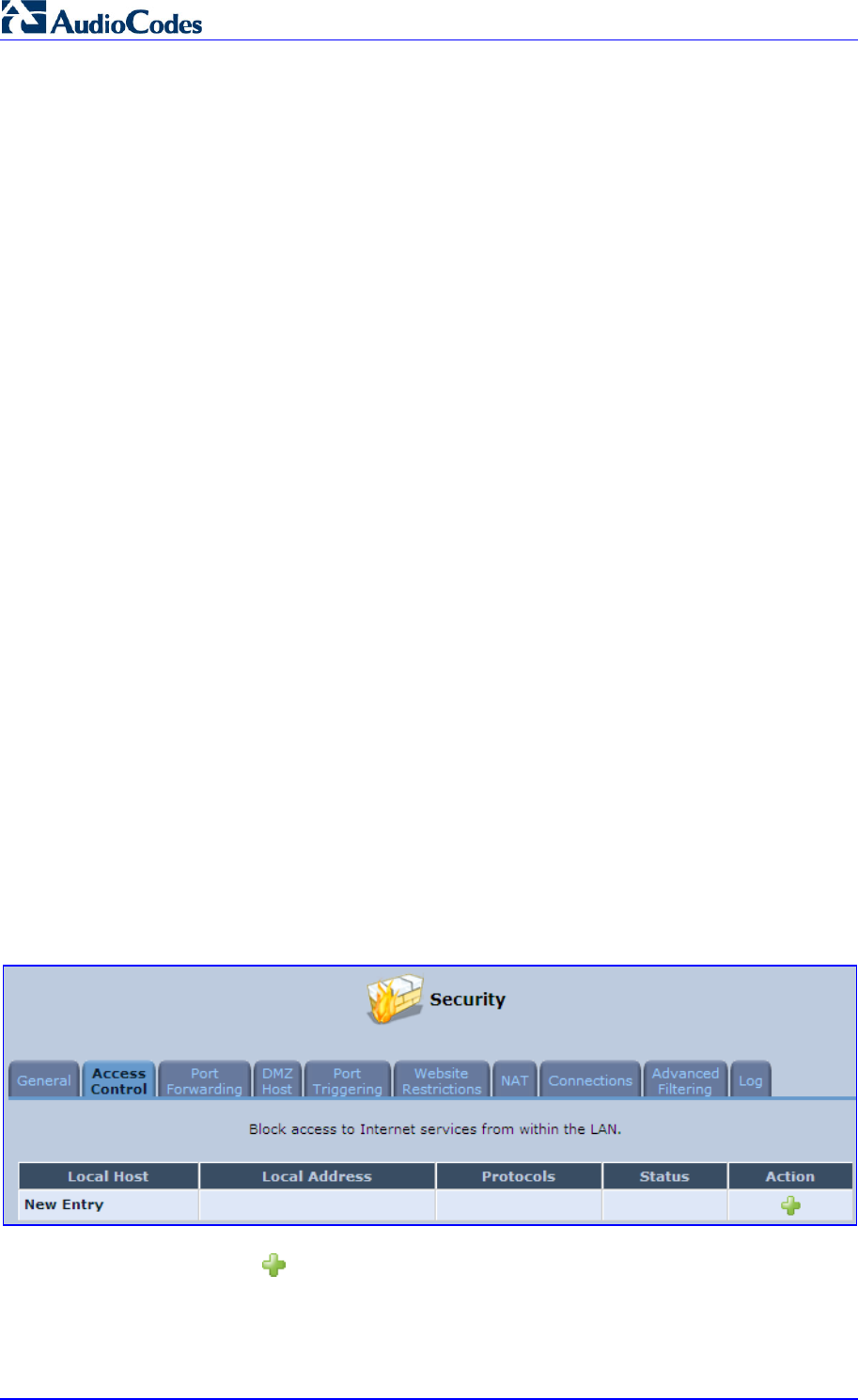
MP252 Multimedia Home Gateway 220 Document #: LTRT-23504
User's Manual
¾ To configure MP252's security settings:
(See the figure 'General Security Level Settings')
1. Choose from among the three predefined security levels described in the table above.
'Maximum Security' is the default setting.
Using the Minimum Security setting may expose the home network to significant
security risks, and thus should only be used, when necessary, for short periods
of time.
2. Check the 'Block IP Fragments' check box to protect your home network from a
common type of hacker attack that could make use of fragmented data packets to
sabotage your home network. Note that some UDP-based services make legitimate use
of IP fragments. You need to allow IP fragments to pass into the home network to make
use of these select services.
3. In the 'TCP Session timeout' field, enter the time-to-live (TTL) in units of seconds for
TCP sessions. The valid range is 1 to 3600 hours (default is an hour).
4. Click OK to save the changes.
14.2 Access Control
You may want to block specific computers within the home network (or even the whole
network) from accessing certain services on the Internet. For example, you may want to
prohibit one computer from surfing the Web, another computer from transferring files using
FTP, and the whole network from receiving incoming e-mail.
Access Control defines restrictions on the types of requests that may pass from the home
network out to the Internet, and thus may block traffic flowing in both directions. In the e-mail
example given above, you may prevent computers in the home network from receiving
e-mail by blocking their outgoing requests to POP3 servers on the Internet.
There are services you should consider blocking, such as popular game and file sharing
servers. For example, to ensure that your employees do not put your business at risk from
illegally traded copyright files, you may want to block several popular P2P and file sharing
applications.
¾ To view and allow/restrict these services:
1. From the menu bar, click the Security menu, and in the screen 'Security', click the
Access Control tab; the screen 'Access Control' opens.
Figure 14-3: Access Control
2. Click the New icon; the screen 'Add Access Control Rule' opens (see the figure
below).
Figure 14-4: Add Access Control Rule
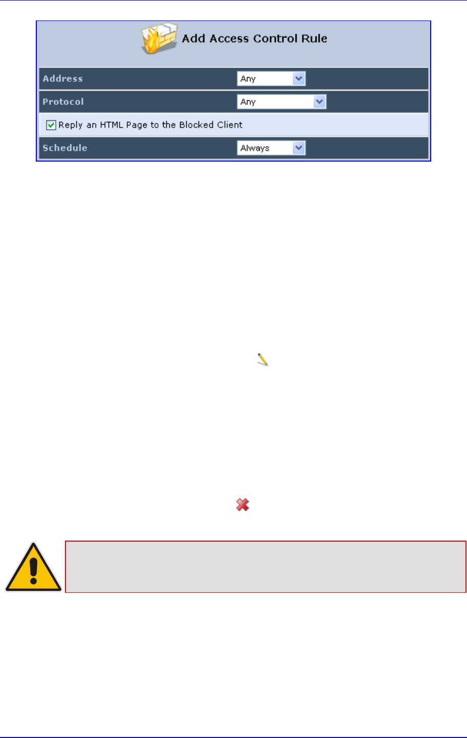
MP252 Multimedia Home Gateway 14. Security
Version 3.4.0 221 June 2011
3. The parameter 'Address' enables you to specify the computer or group of computers for
which you would like to apply the access control rule. You can select between any or a
specific computer address in your LAN. If you choose the 'Specify Address' option, the
screen refreshes, and an 'Add' link appears. Click it to specify a computer address.
Specify an address by creating a 'Network Object'.
4. The parameter 'Protocol' lets you select or specify the type of protocol to be used. In
addition to the list of popular protocols it provides, you may also choose any or a specific
protocol. If you choose option 'Specify Protocol', the screen refreshes and an 'Add' link
appears. Click it to specify a protocol address.
5. The parameter 'Schedule' allows you to define the time period during which this rule
takes effect. You can select between 'Always' or a specific schedule. If you choose the
option 'Specify Schedule', the screen refreshes and an 'Add' link appears. Click it to
specify a schedule.
6. Click OK to save your settings; the 'Access Control' screen displays a summary of the
rule that you just added. Click the Edit icon to edit the access control rule for the
service; the screen 'Edit Service' opens.
7. Select the network group to which you would like to apply the rule and the schedule
during which the rule takes effect.
8. Click OK to save your changes and return to the 'Access Control' screen.
You can disable an access control rule and make the service available without having to
remove the service from 'Access Control'. This can be useful when making the service only
temporarily available and when expecting to reinstate the restriction in the future.
To temporarily disable rule, clear the check box adjacent to the service name.
To reinstate the restriction at a later time, recheck it.
To remove a rule, click the Remove icon for the service; the service is removed from
'Access Control'.
Note: When Web Filtering is enabled, HTTP services cannot be blocked by Access
Control.
14.3 Port Forwarding
By default, MP252 blocks all external users from connecting to or communicating with your
network. Therefore, the system is safe from hackers who may try to intrude on the network
and damage it. However, you may want to expose your network to the Internet in certain
limited and controlled ways to enable some applications to work from the LAN (game, voice
and chat applications, for example) and to enable Internet access to servers in the home
network. The Port Forwarding feature supports both of these functionalities.
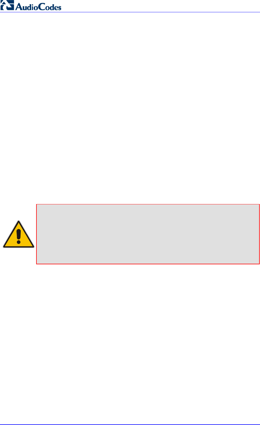
MP252 Multimedia Home Gateway 222 Document #: LTRT-23504
User's Manual
The 'Port Forwarding' screen lets you define the applications that require special handling by
MP252. You must select the application's protocol and the local IP address of the computer
using or providing the service. If required, you can add new protocols in addition to the most
common ones provided by MP252.
For example, to use an FTP application on one of your PCs, select 'FTP' from the list and
enter the local IP address or host name of the designated computer; all FTP-related data
arriving at MP252 from the Internet is then forwarded to the specified computer.
Similarly, to grant Internet users access to servers inside your home network, you must
identify each service that you want to provide and the PC that provides it. For example, to
host a Web server inside the home network you must select 'HTTP' from the list of protocols
and enter the local IP address or host name of the computer that hosts the Web server.
When an Internet user points her browser to the external IP address of MP252, it forwards
the incoming HTTP request to the computer that is hosting the Web server.
Additionally, port forwarding enables you to redirect traffic to a different port instead of the
one to which it was designated. If for example you have a Web server running on your PC on
port 8080 and you want to grant access to this server to anyone who accesses MP252 via
HTTP, do the following:
Define a port forwarding rule for the HTTP service, with the PC's IP or host name.
Specify 8080 in the field 'Forward to Port'.
All incoming HTTP traffic is now forwarded to the PC running the Web server on port 8080.
When setting a port forwarding service, you must ensure that the port is not already in use by
another application, which may stop functioning. A common example is when using SIP
signaling in Voice over IP - the port used by MP252's VoIP application (5060) is the same
port on which port forwarding is set for LAN SIP agents.
Note: Some applications, such as FTP, TFTP, PPTP and H323, require the support of
special specific Application Level Gateway (ALG) modules in order to work
inside the home network. Data packets associated with these applications
contain information that allows them to be routed correctly. An ALG is needed to
handle these packets and ensure that they reach their intended destinations.
MP252 is equipped with a robust list of ALG modules in order to enable
maximum functionality in the home network.
The ALG is automatically assigned based on the destination port.
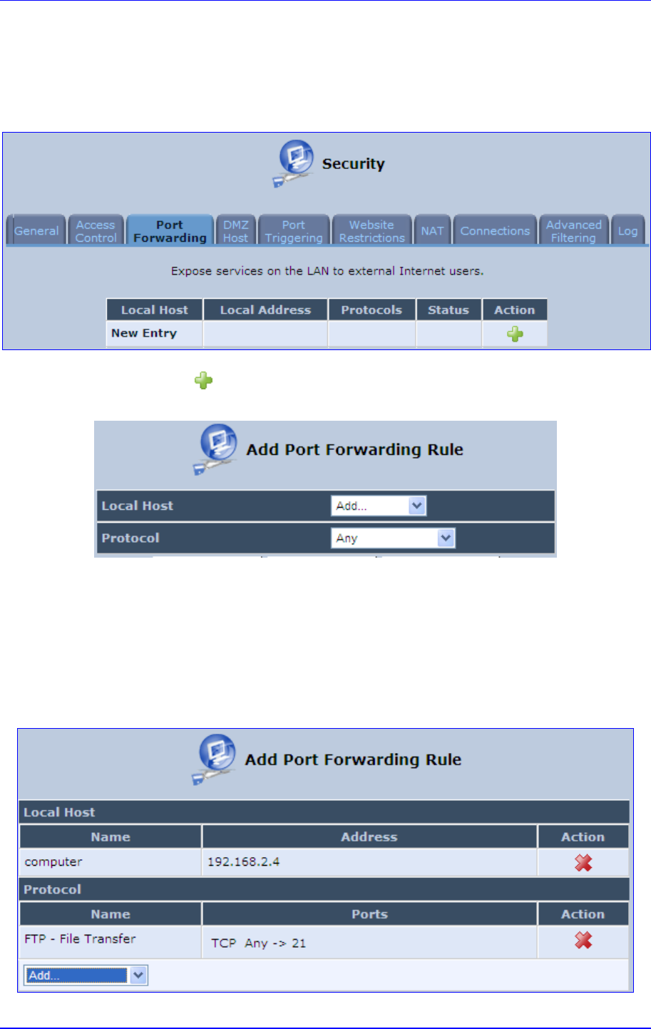
MP252 Multimedia Home Gateway 14. Security
Version 3.4.0 223 June 2011
¾ To add a new port forwarding service :
1. From the menu bar, click the Security menu, and in the screen 'Security', click the Port
Forwarding tab; the screen 'Port Forwarding' opens.
Figure 14-5: Port Forwarding Screen
2. Click the New icon; the screen 'Add Port Forwarding Rule' opens.
Figure 14-6: Add Port Forwarding Rule
3. From the ‘Local Host’ drop-down list, select the network object (defined in Section 4.5.2
on page 46) or define one now by selecting the ‘User Defined’ option. This is the IP
address or host name of the computer that provides the service (the 'server'). Note:
Only one LAN computer can be assigned to provide a specific service or application.
4. From the ‘Protocol’ drop-down list, select the type of protocol (defined in Section 4.5.3
on page 47) or select ‘User Defined’ to define one now. You can select multiple
protocols for this rule.
Figure 14-7: Selecting Protocol Type
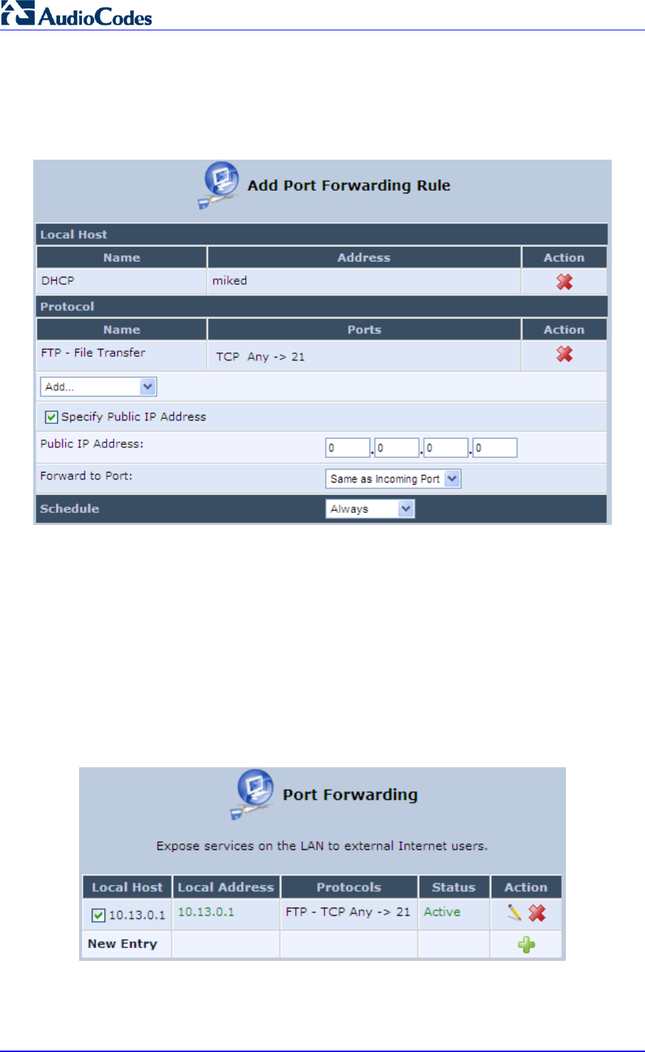
MP252 Multimedia Home Gateway 224 Document #: LTRT-23504
User's Manual
5. Click the Advanced button to configure advanced settings:
a. Select the 'Specify Public IP Address' check box if you want to apply this rule on
MP252’s non-default IP address defined in the ‘NAT’ screen (see Section 14.7 on
page 232). Enter the additional external IP address in the 'Public IP Address' field.
Figure 14-8: Specifying Public IP Address
b. By default, MP252 forwards traffic to the same port as the incoming port. If you
wish to redirect traffic to a different port, then from the 'Forward to Port' drop-down
list, select the 'Specify', and then enter the port number in the field provided.
c. By default, the rule is always active. However, you can select a schedule rule that
defines the time during which the rule may be active. From the 'Schedule'
drop-down list, select a defined Schedule rule (defined in Section 4.5.1 on page 43)
or define a new one quickly by selecting 'User Defined'.
6. Click OK to save changes.
You can disable a port forwarding rule to make a service unavailable without having to
remove the rule from the screen 'Port Forwarding'. This can be useful when making the
service temporarily unavailable and when expecting to reinstate it in the future.
Figure 14-9: Select Check Box of Port Forwarding Rule (Active)
To temporarily disable a rule, clear the check box next to the service name.
To reinstate it at a later time, select the check box.

MP252 Multimedia Home Gateway 14. Security
Version 3.4.0 225 June 2011
To remove a rule, click the Remove icon for the service; the service is permanently
removed.
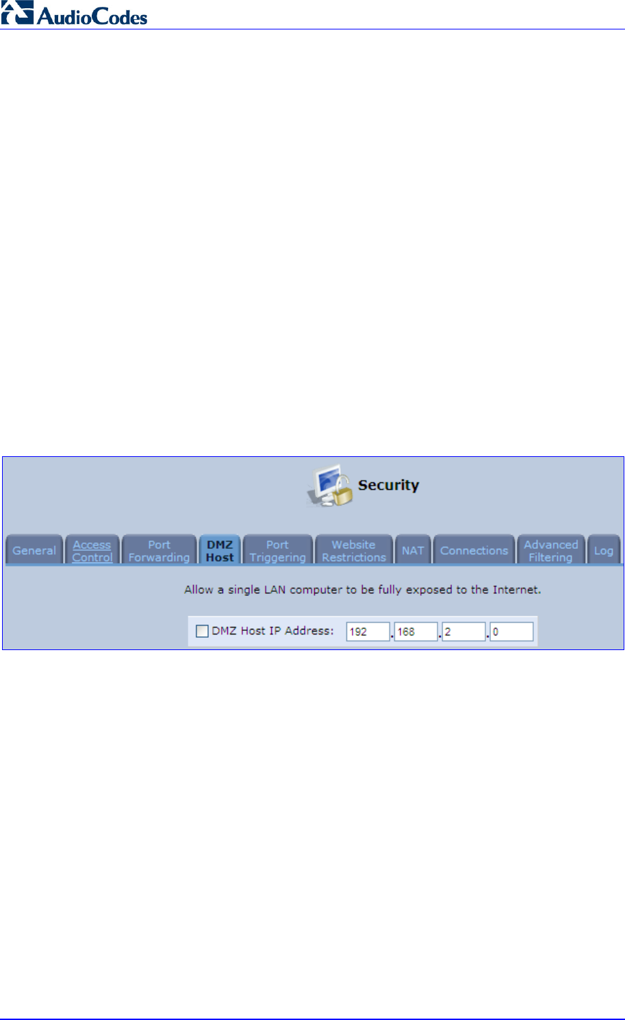
MP252 Multimedia Home Gateway 226 Document #: LTRT-23504
User's Manual
14.4 DMZ Host
The DMZ (Demilitarized) Host feature allows one local computer to be exposed to the
Internet. Designate a DMZ host to:
Use a special-purpose Internet service, such as an on-line game or video-conferencing
program, that is not present in the Local Servers list and for which no port range
information is available.
To expose one computer to all services, without restriction, irrespective of security.
Warning: A DMZ host is not protected by the firewall and may be vulnerable to attack.
Designating a DMZ host may also put other computers in the home network at risk. When
designating a DMZ host, you must consider the security implications and protect it if
necessary.
An incoming request for access to a service in the home network, such as a Web-server, is
fielded by MP252. MP252 forwards this request to the DMZ host (if one is designated) unless
the service is being provided by another PC in the home network (assigned in Local
Servers), in which case that PC receives the request instead.
¾ To designate a local computer as a DMZ Host:
1. From the menu bar, click the Security menu, and in the screen 'Security', click the DMZ
Host tab; the screen 'DMZ Host' opens.
Figure 14-10: DMZ Host
2. Enter the local IP address of the computer to be designated as a DMZ host. Note that
only one LAN computer can be a DMZ host at any time.
3. Click OK to save your changes and return to the screen 'DMZ Host'.
You can disable the DMZ host so that it does not fully exposed to the Internet, but keep its IP
address recorded on the 'DMZ Host' screen. This may be useful if you wish to disable the
DMZ host but expect that you may want to enable it again in the future.
To disable the DMZ host so that it is not fully exposed to the Internet, clear the
check-box next to the DMZ IP designation and click OK.
To re-enable the DMZ host later, recheck the check-box.
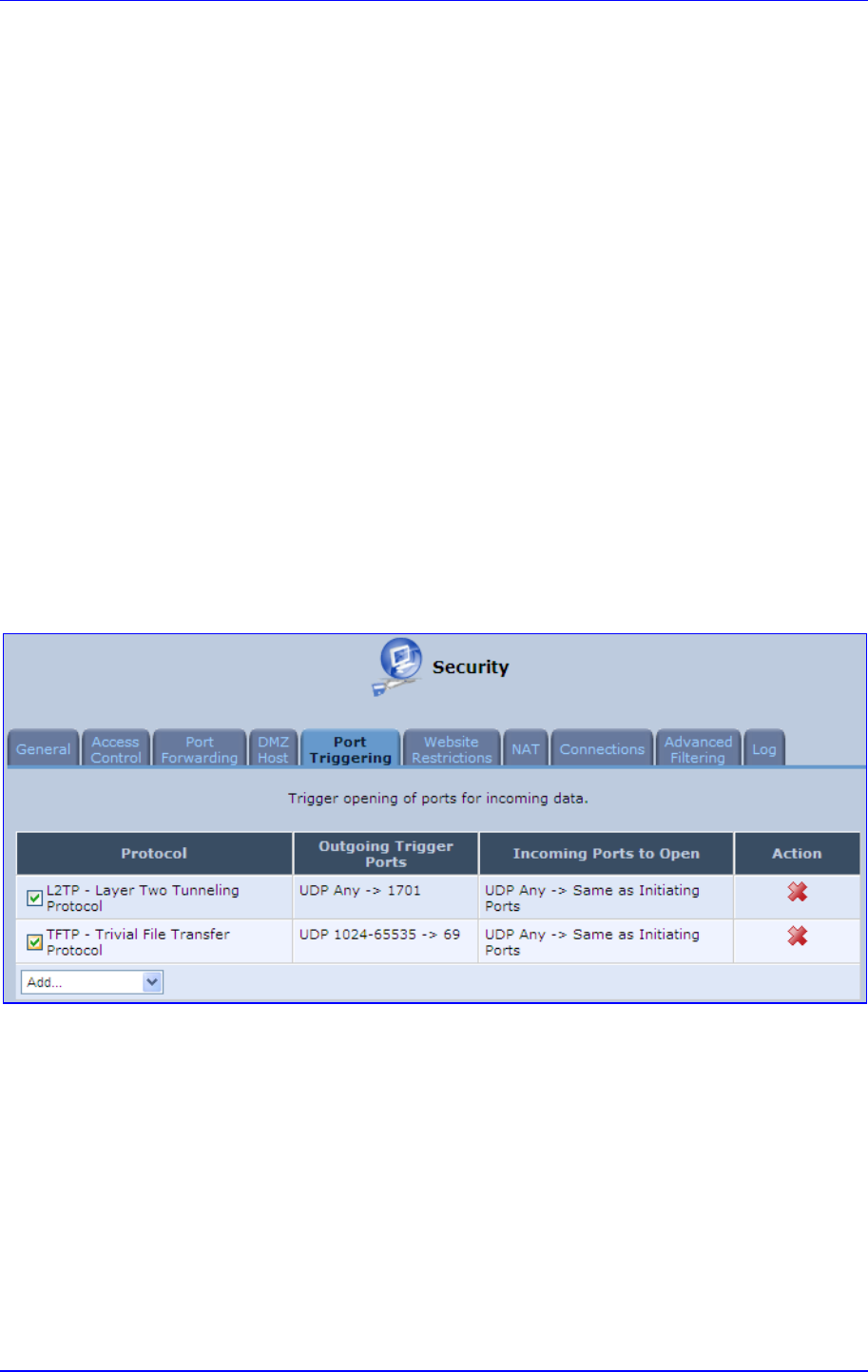
MP252 Multimedia Home Gateway 14. Security
Version 3.4.0 227 June 2011
14.5 Port Triggering
Port triggering can be used for dynamic port forwarding configuration. By setting port
triggering rules, you can allow inbound traffic to arrive at a specific LAN host, using ports
different than those used for the outbound traffic. This is called port triggering since the
outbound traffic triggers to which ports inbound traffic is directed.
For example, consider a gaming server that is accessed using UDP protocol on port 222.
The gaming server responds by connecting the user using UDP on port 333 when starting
gaming sessions. In such a case you must use port triggering, since this scenario conflicts
with the following default firewall settings:
The firewall blocks inbound traffic, by default.
The server replies to MP252's IP, and the connection is not sent back to your host, since
it is not part of a session.
To solve this, you need to define a Port Triggering entry, which allows inbound traffic on UDP
port 333, only after a LAN host generated traffic to UDP port 222. This results in accepting
the inbound traffic from the gaming server and sending it back to the LAN Host which
originated the outgoing traffic to UDP port 222.
¾ To view port triggering settings:
1. From the menu bar, click the Security menu, and in the screen 'Security', click the Port
Triggering tab; the screen 'Port Triggering' opens. The screen lists all port triggering
entries.
Figure 14-11: Port Triggering
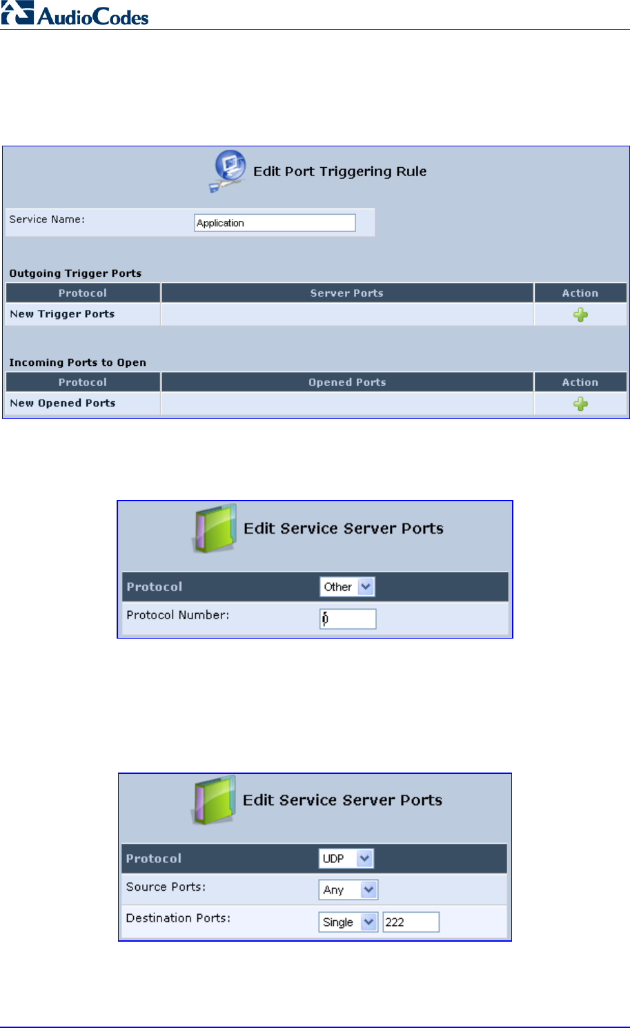
MP252 Multimedia Home Gateway 228 Document #: LTRT-23504
User's Manual
¾ To add an entry for the gaming example above:
1. From the drop-down list, select 'User Defined' to add an entry; the screen 'Edit Service'
opens.
Figure 14-12: Adding Port Triggering Rules
2. Enter a name for the service (e.g., 'game_server'), and then click the link New Trigger
Ports; the screen 'Edit Service Server Ports' opens.
Figure 14-13: Edit Service Server Ports
3. In the 'Protocol' drop-down list, select 'UDP'; the screen refreshes, providing source and
destination port options.
4. Leave the 'Source Ports' drop-down list at its default 'Any'. In the 'Destination Ports'
drop-down list, select 'Single'; the screen refreshes again, providing an additional field
in which you should enter '222' as the destination port.
Figure 14-14: Edit Service Server Ports
5. Click OK to save the settings.
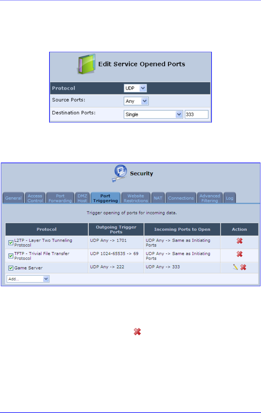
MP252 Multimedia Home Gateway 14. Security
Version 3.4.0 229 June 2011
6. In the screen 'Edit Service', click the link New Opened Ports; the screen 'Edit Service
Opened Ports' opens.
7. Similar to the trigger ports screen, select UDP as the protocol, leave the source port at
'Any', and enter a 333 as the single destination port.
Figure 14-15: Edit Service Opened Ports
8. Click OK to save the settings; the screen 'Edit Service' presents your entered
information. Click OK again to save the port triggering rule; the screen 'Port Triggering'
now includes the new port triggering entry.
Figure 14-16: New Port Triggering Rule
You can disable a port triggering rule without having to remove it from the screen 'Port
Triggering':
To temporarily disable a rule, clear the check box corresponding to the service name.
To reinstate it later, simply reselect the check box.
To remove a rule, click the Remove icon for the service; the service is permanently
removed.
There may be a few default port triggering rules listed when you first access the port
triggering screen. Note that disabling these rules may result in impaired MP252 functionality.
14.6 Website Restrictions
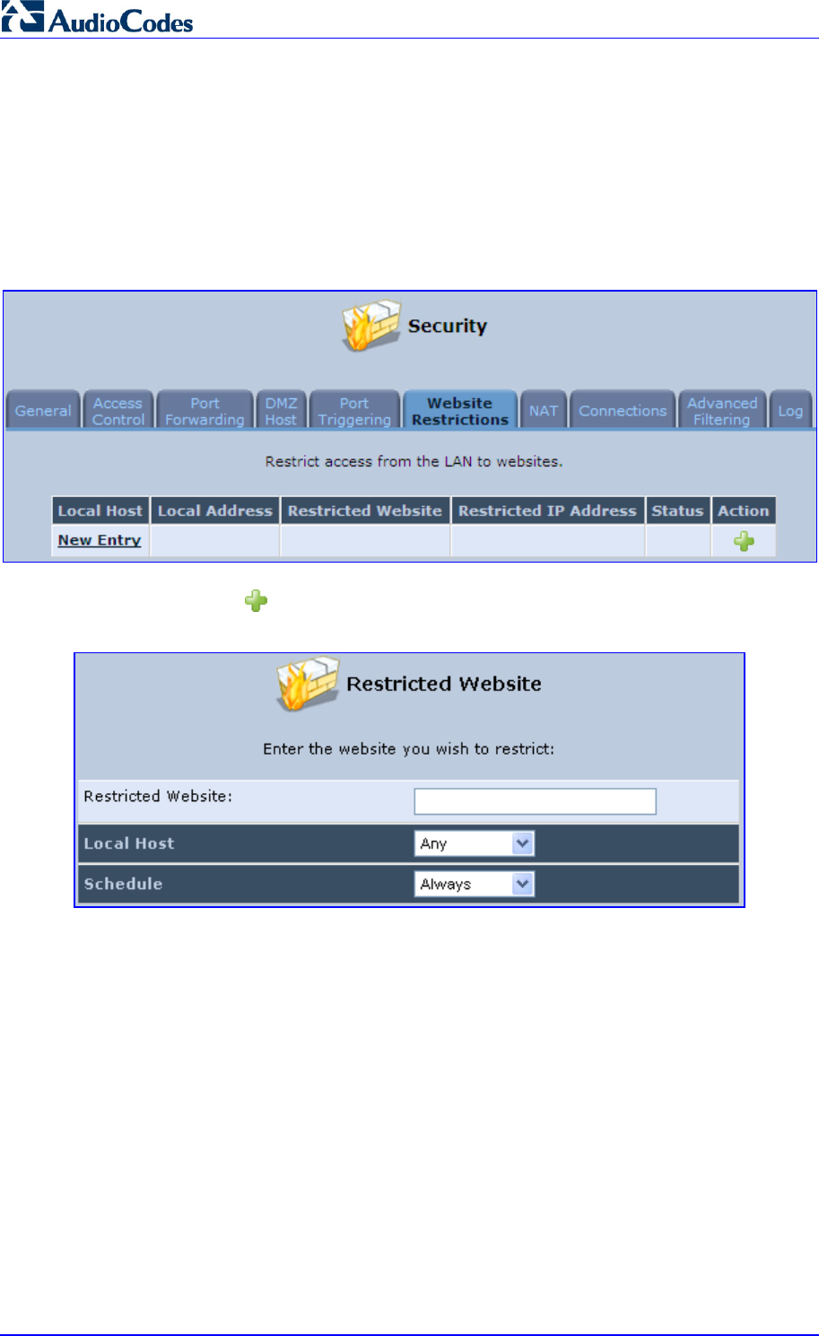
MP252 Multimedia Home Gateway 230 Document #: LTRT-23504
User's Manual
You can configure MP252 to block specific Internet websites so that they cannot be
accessed from computers in the home network. Moreover, restrictions can be applied to a
comprehensive and automatically-updated table of sites to which access is not
recommended.
¾ To block access to a website:
1. From the menu bar, click the Security menu, and in the screen 'Security', click the
Website Restrictions tab; the screen 'Website Restrictions' opens.
Figure 14-17: Website Restrictions
2. Click the New icon; the 'Restricted Website' screen appears.
Figure 14-18: Restricted Website
3. Enter the website address (IP address or URL) that you would like to make inaccessible
from your home network (all Web pages within the site are also blocked). If the website
address has multiple IP addresses, MP252 resolves all additional addresses and
automatically adds them to the restrictions table.
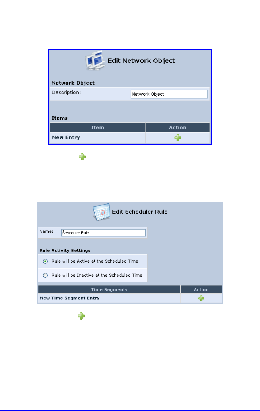
MP252 Multimedia Home Gateway 14. Security
Version 3.4.0 231 June 2011
4. The 'Local Host' drop-down list provides you the ability to specify the computer or group
of computers for which you would like to apply the website restriction. You can select
between any or a specific computer address in your LAN. If you choose the option 'User
Defined', the screen refreshes and the 'Edit Network Object' appears:
Figure 14-19: Add a Specific Host
5. Click the New icon to specify a computer address. Specify an address creating a
'Network Object'.
6. The parameter Schedule allows you to define the time period during which this rule
takes effect. You can select between 'Always' or a specific schedule. If you choose the
option 'User Defined', the screen 'Edit Scheduler Rule' appears:
Figure 14-20: Add a Specific Schedule
7. Click the New icon to specify the time segment, and then click OK.
8. Click OK to save the settings; MP252 attempts to find the site. 'Resolving...' appears in
the Status column while the site is being located (the URL is 'resolved' into one or more
IP addresses).
9. Click the Refresh button to update the status if necessary. If the site is successfully
located, 'Resolved' appears in the status bar; if not, 'Hostname Resolution Failed'
appears.
¾ If MP252 fails to locate the website:
1. Use a Web browser to verify that the website is available. If it is, then you probably
entered the website address incorrectly.

MP252 Multimedia Home Gateway 232 Document #: LTRT-23504
User's Manual
2. If the website is unavailable, return to the screen 'Website Restrictions' later and click
the button Resolve Now to verify that the website can be found and blocked by MP252.
3. You can edit the website restriction by modifying its entry under the column 'Local Host'
in the screen 'Website Restrictions'.
¾ To modify an entry:
1. Click the icon Edit for the restriction; the screen 'Restricted Website' opens. Modify the
website address, group or schedule as required.
2. Click OK to save your changes and return to the screen 'Website Restrictions'.
¾ To ensure that all current IP addresses corresponding to the restricted
websites are blocked:
1. Click the button Resolve Now; MP252 checks each of the restricted website addresses
and ensures that all IP addresses at which this website can be found are included in the
IP addresses column.
You can disable a restriction to make a website available again without having to remove it
from the screen 'Website Restrictions'. This can be useful when making the website
temporarily available and when expecting to block it again in the future.
To temporarily disable a rule, clear the check box adjacent to the service name.
To reinstate it at a later time, recheck the check box.
To remove a rule, click the Remove icon for the service; the service is permanently
removed.
14.7 NAT
MP252 features a configurable Network Address Translation (NAT) and Network Address
Port Translation (NAPT) mechanism, allowing you to control the network addresses and
ports of packets routed through your gateway. When enabling multiple computers on your
network to access the Internet using a fixed number of public IP addresses, you can statically
define which LAN IP address will be translated to which NAT IP address and/or ports.
By default, MP252 operates in NAPT routing mode. However, you can control your network
translation by defining static NAT/NAPT rules. Such rules map LAN computers to NAT IP
addresses. The NAT/NAPT mechanism is useful for managing Internet usage in your LAN,
or complying with various application demands. For example, you can assign your primary
LAN computer with a single NAT IP address, in order to assure its permanent connection to
the Internet. Another example is when an application server with which you wish to connect,
such as a security server, requires that packets have a specific IP address – you can define
a NAT rule for that address.
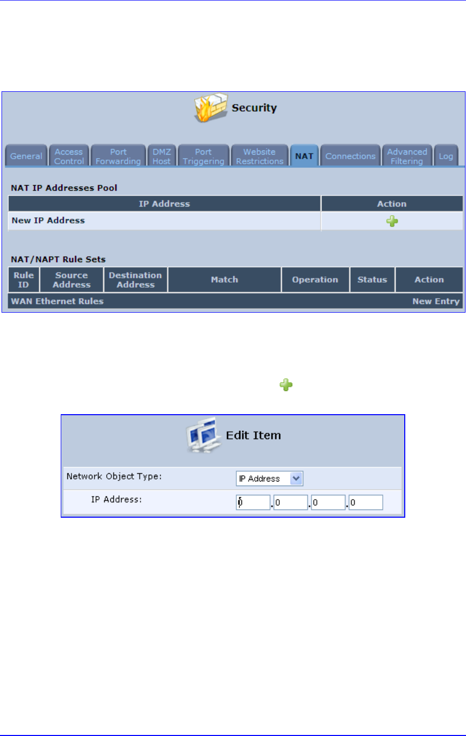
MP252 Multimedia Home Gateway 14. Security
Version 3.4.0 233 June 2011
¾ To define NAT:
1. From the menu bar, click the Security menu, and in the screen 'Security', click the NAT
tab; the screen 'NAT' opens.
Figure 14-21: NAT Screen
2. Before configuring NAT/NAPT rules, you must first enter the additional public IP
addresses obtained from your ISP as your NAT IP addresses, in the 'NAT IP Addresses
Pool' section. The primary IP address used by the WAN device for dynamic NAPT
should not be added to this table.
a. To add a NAT IP address, click the New icon; the 'Edit Item' screen appears.
Figure 14-22: Adding a NAT IP Address
b. From the 'Network Object Type' drop-down list, select between IP address, subnet
or range, and then enter the information respectively, and click OK to save the
settings.
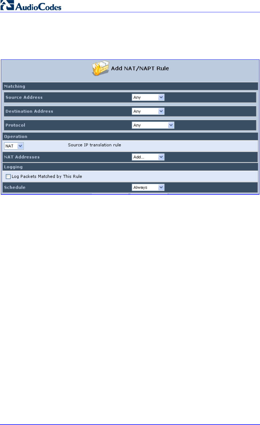
MP252 Multimedia Home Gateway 234 Document #: LTRT-23504
User's Manual
3. To add a new NAT/NAPT rule:
a. In the 'NAT/NAPT Rule Sets' section, click the New Entry link; the 'Add NAT/NAPT
Rule' screen appears.
Figure 14-23: Adding NAT/NAPT Rule
This screen is divided into two main sections: 'Matching' and 'Operation'. The 'Matching'
section defines the LAN addresses to be translated to the external addresses, which are
defined in the 'Operation' section.
4. 'Matching' section (define characteristics of the packets matching the rule):
a. Source Address: source address of packets sent or received by MP252. You can
select the computer or group of computers on which you would like to apply the
rule. To apply the rule on all the LAN hosts, select 'Any' . If you would like to add a
new address, select the 'User Defined'. This commences a sequence to add a new
Network Object, representing the new host.
b. Destination Address: destination address of packets sent or received by MP252.
This address can be configured in the same manner as the source address. This
entry enables further filtration of the packets.
c. Protocol: specifies a traffic protocol. Selecting the 'Show All Services' option
expands the list of available protocols. Select a protocol or add a new one using the
'User Defined' option. This commences a sequence that adds a new Service,
representing the protocol. Using a protocol requires observing the relationship
between a client and a server to distinguish between the source and destination
ports.

MP252 Multimedia Home Gateway 14. Security
Version 3.4.0 235 June 2011
5. Operation section (define the operation to apply on the IP addresses, matching the
criteria defined above): NAT or NAPT.
• NAT Addresses: NAT address into which the original IP address is translated. The
drop-down list displays all of your available NAT addresses/ranges from which you
can select an entry. If you would like to add a single address or a sub-range from
the given pool/range, select the 'User Defined' option. This commences a
sequence that adds a new Network Object, representing the new host.
• NAPT Address: NAPT address into which the original IP address is translated.
The drop-down list displays all of your available NAPT addresses/ranges from
which you can select an entry. If you would like to add a single address or a
sub-range from the given pool/range, select the 'User Defined' option. This
commences a sequence that adds a new Network Object, representing the new
host. . Note, that in this case the network object may only be an IP address, as
NAPT is port-specific.
♦ NAPT Ports: specify the port(s) of the IP address into which the original IP
address is translated. Enter a single port or select 'Range' (the screen
refreshes, enabling you to enter a range of ports).
6. Select the 'Log Packets Matched by This Rule' check box to log the first packet from a
connection that was matched by this rule.
7. By default, the 'Schedule' rule is always active. However, you can configure scheduler
rules to define time segments during which the rule may be active.
8. Click OK to save the settings.
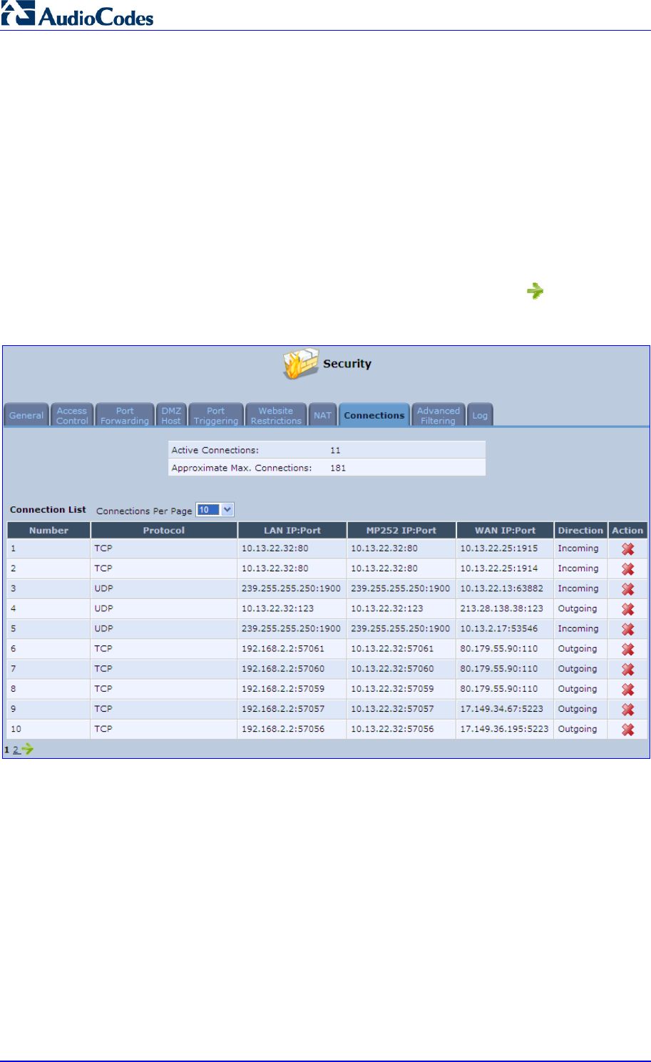
MP252 Multimedia Home Gateway 236 Document #: LTRT-23504
User's Manual
14.8 Connections
The connection list displays all the connections that are currently open, as well as various
details and statistics. You can use this list to close an undesired connection by clicking its
corresponding action icon. The basic display includes the name of the protocol, the different
ports it uses, and the direction in which the connection was initiated.
¾ To view currently open connections:
1. From the menu bar, click the Security menu, and in the screen 'Security', click the
Connections tab; the screen 'Connections' opens.
2. From the Connections Per Page drop-down list, select the number of connections that
you want displayed per page. To browse to the next page, click the icon or the page
number located at the bottom left of the page.
Figure 14-24: Connections Screen
To display additional details in the Connection list, click the Advanced button.
The 'Approximate Max. Connections' value displays the amount of additional concurrent
connections possible.
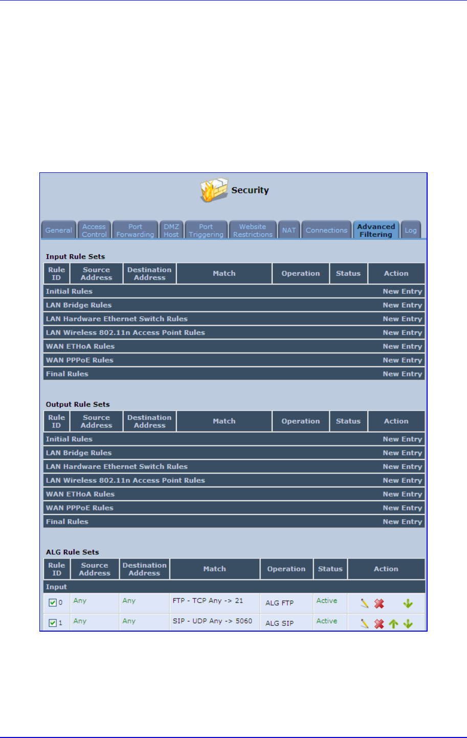
MP252 Multimedia Home Gateway 14. Security
Version 3.4.0 237 June 2011
14.9 Advanced Filtering
Advanced filtering is designed to allow comprehensive control over the firewall's behavior.
You can define specific input and output rules, control the order of logically similar sets of
rules and make a distinction between rules that apply to WAN and LAN devices.
¾ To view MP252's advanced filtering options:
From the menu bar, click the Security menu, and in the screen 'Security', click the
Advanced Filtering tab; the 'Advanced Filtering' opens.
Figure 14-25: Advanced Filtering
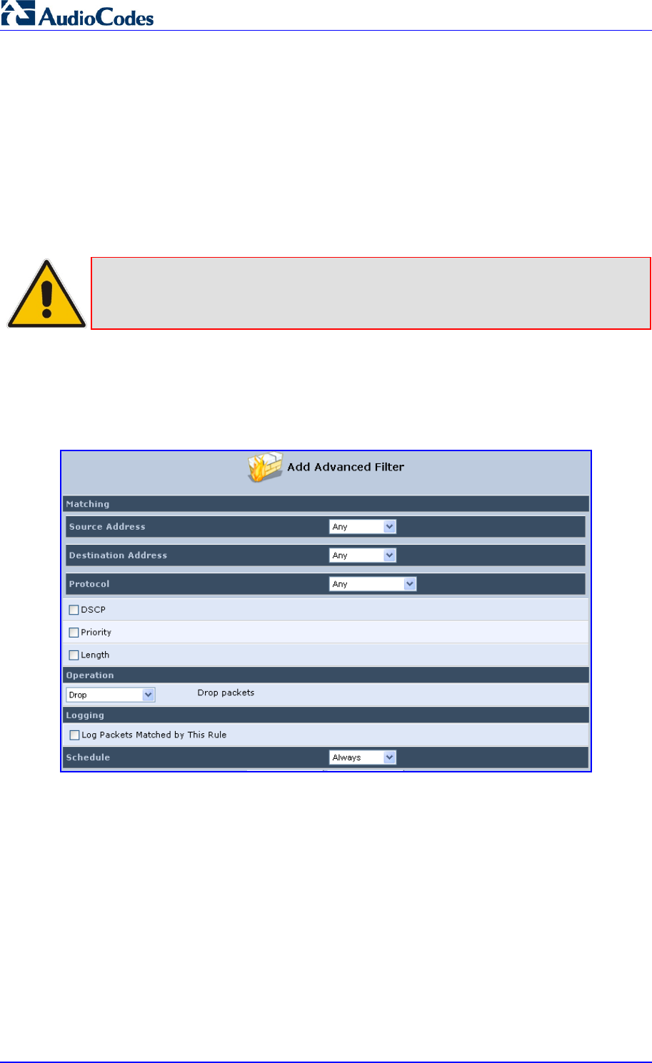
MP252 Multimedia Home Gateway 238 Document #: LTRT-23504
User's Manual
This screen is divided into two identical sections, one for 'Input Rule Sets' and the other for
'Output Rule Sets', which are for configuring inbound and outbound traffic, respectively. Each
section is comprised of subsets, which can be grouped into three main subjects:
1. Initial rules - rules defined here are applied first, on all MP252 devices.
2. Network devices rules - rules can be defined per MP252.
3. Final rules - rules defined here are applied last, on all MP252 devices.
Numerous rules are automatically inserted by the firewall to provide improved security and
block harmful attacks.
Note: The order of appearance of the firewall rules determines the sequence by which
they are applied.
¾ To configure an advanced filtering rule:
1. After choosing the traffic direction and the device on which to set the rule, click the
corresponding link New Entry; the screen 'Add Advanced Filter' opens.
Figure 14-26: Add Advanced Filter
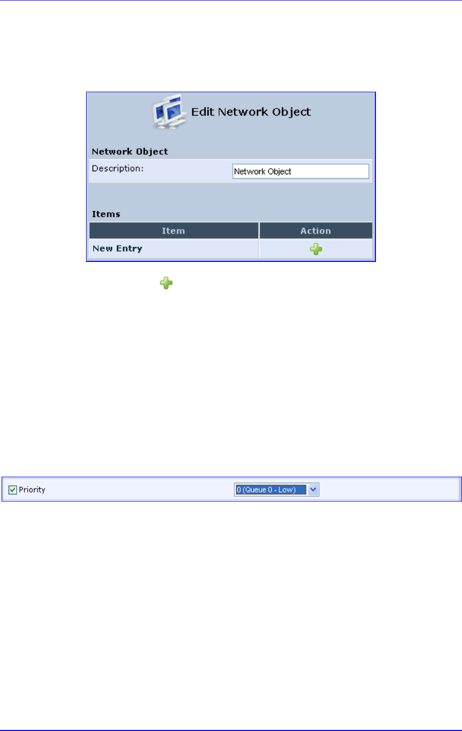
MP252 Multimedia Home Gateway 14. Security
Version 3.4.0 239 June 2011
2. In the section 'Matching', define a match between IP addresses and a traffic protocol:
a. Configure the source address of the packets sent to or received from the network
object. To add an address, select the option 'User Defined' from the drop-down list;
the screen 'Edit Network Object' appears.
Figure 14-27: Add a Specific Host
Click the New icon; this commences a sequence that adds a new network
object.
b. Configure the destination address of the packets sent to or received from the
network object. This address can be configured in the same manner as the source
address.
c. From the 'Protocol' drop-down list, select a specific traffic protocol or add a new
one (by selecting 'User Defined'); the 'Edit Services' screen appears. Click the link
New Server Ports; this commences a sequence that adds a new protocol.
3. Select the check box 'DSCP' to mark a DSCP value on packets matching this rule; the
screen refreshes, allowing you to enter the hexadecimal value of the DSCP.
4. Select the check box 'Priority' to add a priority to the rule; the screen refreshes, allowing
you to select between one of eight priority levels, zero being the lowest and seven the
highest (each priority level is mapped to low/medium/high priority). This sets the priority
of a packet on the connection matching the rule, while routing the packet.
Figure 14-28: Set Priority Rule
5. Select the check box 'Length' to specify the length of packets or the length of their data
portion.
6. In the section 'Operation', define the action of the rule:
• Drop: Deny access to packets that match the source and destination IP addresses
and service ports defined in 'Matching'.
• Reject: Deny access to packets that match the source and destination IP
addresses and service ports defined in 'Matching' and sends and sends an ICMP
error or a TCP reset to the origination peer.
• Accept Connection: Allow access to packets that match the source and
destination IP addresses and service ports defined in 'Matching'. The data transfer
session is handled using Stateful Packet Inspection (SPI).
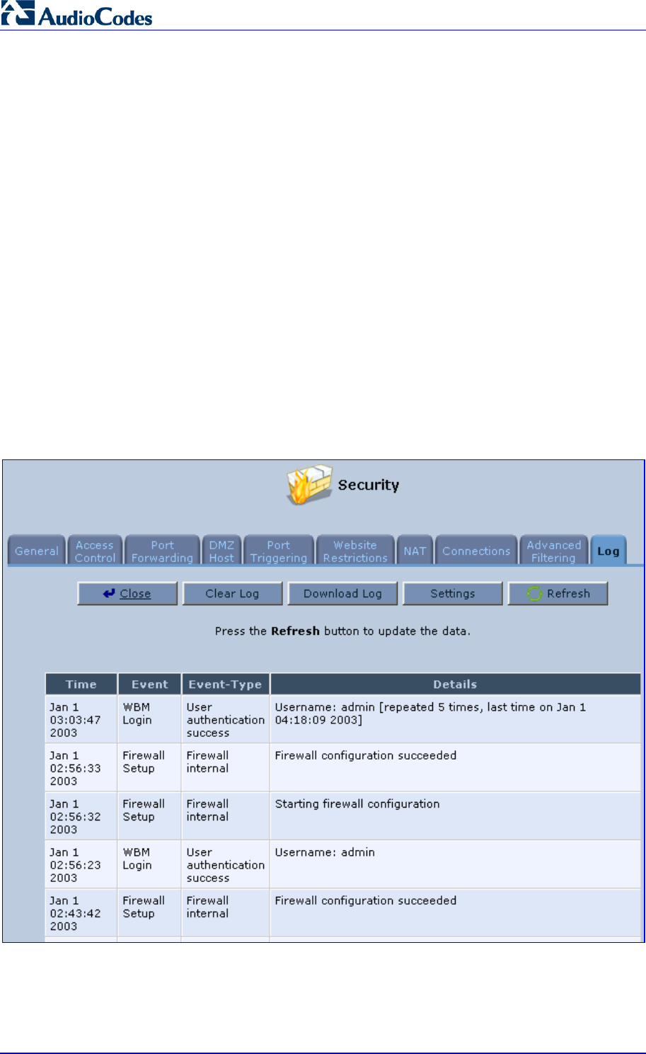
MP252 Multimedia Home Gateway 240 Document #: LTRT-23504
User's Manual
• Accept Packet: Allow access to packets that match the source and destination IP
addresses and service ports defined in 'Matching'. The data transfer session is not
handled using Stateful Packet Inspection (SPI), meaning that other packets that
match this rule are not automatically allowed access. For example, this can useful
when creating rules that allow broadcasting.
7. Under the section 'Logging', select the parameter 'Log Packets Matched By This Rule'
to log the first packet from a connection that was matched by this rule.
8. By default, the 'Schedule' rule is always active. However, you can configure scheduler
rules to define time segments during which the rule may be active.
9. Click OK to save the settings.
14.10 Security Log
The Security log displays a list of firewall-related events, including attempts to establish
inbound and outbound connections, attempts to authenticate at an administrative interface
(Web-based management or Telnet terminal), firewall configuration and system start-up.
¾ To view the Security Log:
1. From the menu bar, click the Security menu, and in the screen 'Security', click the Log
tab; the screen 'Log' opens.
Figure 14-29: Security Log
2. The log table displays the following:
• Time: to determine the time the event occurred.
• Event: type of event. There are five types of events:
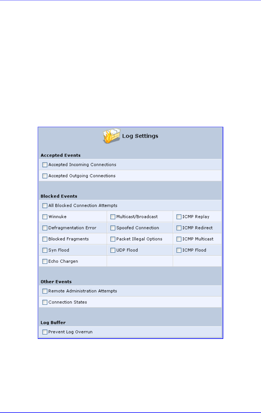
MP252 Multimedia Home Gateway 14. Security
Version 3.4.0 241 June 2011
♦ Inbound Traffic: The event is a result of an incoming packet.
♦ Outbound Traffic: The event is a result of outgoing packet.
♦ Firewall Setup: Configuration message.
♦ WBM Login: Indicates that a user has logged in to WBM.
♦ CLI Login: Indicates that a user has logged in to CLI (via Telnet).
• Event-Type: textual description of the event:
♦ Blocked: The packet was blocked. The message is color-coded red.
♦ Accepted: The packet was accepted. The message is color-coded green.
• Details: details of the packet or the event, such as protocol, IP addresses, ports,
etc.
¾ To change the security log settings:
1. In the 'Log' screen, click Settings; the screen 'Log Settings' opens.
Figure 14-30: Security Log Settings
2. Select the types of activities for which you would like to have a log message generated.
• Accepted Events:
♦ Accepted Incoming Connections: Write a log message for each successful
attempt to establish an inbound connection to the home network.
♦ Accepted Outgoing Connections: Write a log message for each successful
attempt to establish an outgoing connection to the public network.
• Blocked Events:

MP252 Multimedia Home Gateway 242 Document #: LTRT-23504
User's Manual
♦ All Blocked Connection Attempts: Write a log message for each blocked
attempt to establish an inbound connection to the home network or vice versa.
You can enable logging of blocked packets of specific types by disabling this
option, and enabling some of the more specific options below it.
♦ Specific Events: Specify the blocked events that should be monitored. Use
this to monitor specific event such as SynFlood. A log message is generated if
either the corresponding check-box is checked, or the check-box 'All Blocked
Connection Attempts' is checked.
• Other Events:
♦ Remote Administration Attempts: Write a log message for each
remote-administration connection attempt, whether successful or not.
♦ Connection States: Provide extra information about every change in a
connection opened by the firewall. Use this option to track connection
handling by the firewall and Application Level Gateways (ALGs).
• Log Buffer:
♦ Prevent Log Overrun: Select this check box in order to stop logging firewall
activities when the memory allocated for the log fills up.
3. Click OK to save the settings.

Version 3.4.0 243 July 2011
MP252 Multimedia Home Gateway 15. Advanced Networking Features
15 Advanced Networking Features
This chapter describes various advanced networking features such as DHCP.
15.1 IP Address Distribution
The MP252's Dynamic Host Configuration Protocol (DHCP) server makes it possible to
easily add computers that are configured as DHCP clients to the home network. It provides a
mechanism for allocating IP addresses and delivering network configuration parameters to
such hosts. MP252's default DHCP server is the LAN bridge.
A client (host) sends out a broadcast message on the LAN requesting an IP address for itself.
The DHCP server then checks its list of available addresses and leases a local IP address to
the host for a specific period of time and simultaneously designates this IP address as
`taken'. At this point, the host is configured with an IP address for the duration of the lease.
The host can choose to renew an expiring lease or let it expire. If it chooses to renew a lease
then it also receives current information about network services, as it did with the original
lease, allowing it to update its network configurations to reject any changes that may have
occurred since it first connected to the network. If the host wishes to terminate a lease before
its expiration it can send a release message to the DHCP server, which then makes the IP
address available for use by others.
The MP252 embedded DHCP server provides the following features:
Displays a list of all DHCP host devices connected to MP252
Defines the range of IP addresses that can be allocated to the LAN
Defines the length of time for which dynamic IP addresses are allocated
Provides the above configurations for each LAN device and can be configured and
enabled / disabled separately for each LAN device
Can assign a static lease to a LAN PC so that it receives the same IP address each time
it connects to the network even if this IP address is within the range of addresses that
the DHCP server may assign to other computers
Provides the DNS server with the host name and IP address of each PC that is
connected to the LAN
In addition, MP252 can act as a DHCP relay, escalating DHCP responsibilities to a WAN
DHCP server. In this case, MP252 acts merely as a router, while its LAN hosts receives their
IP addresses from an external DHCP server on the WAN.
With MP252's optional Zero Configuration Technology feature, the IP Auto Detection method
detects statically-defined IP addresses in addition to MP252's DHCP clients. It learns all the
IP addresses on the LAN and integrates the collected information with the database of the
DHCP server. This allows the DHCP server to issue valid leases, thus avoiding conflicting IP
addresses used by other computers in the network.
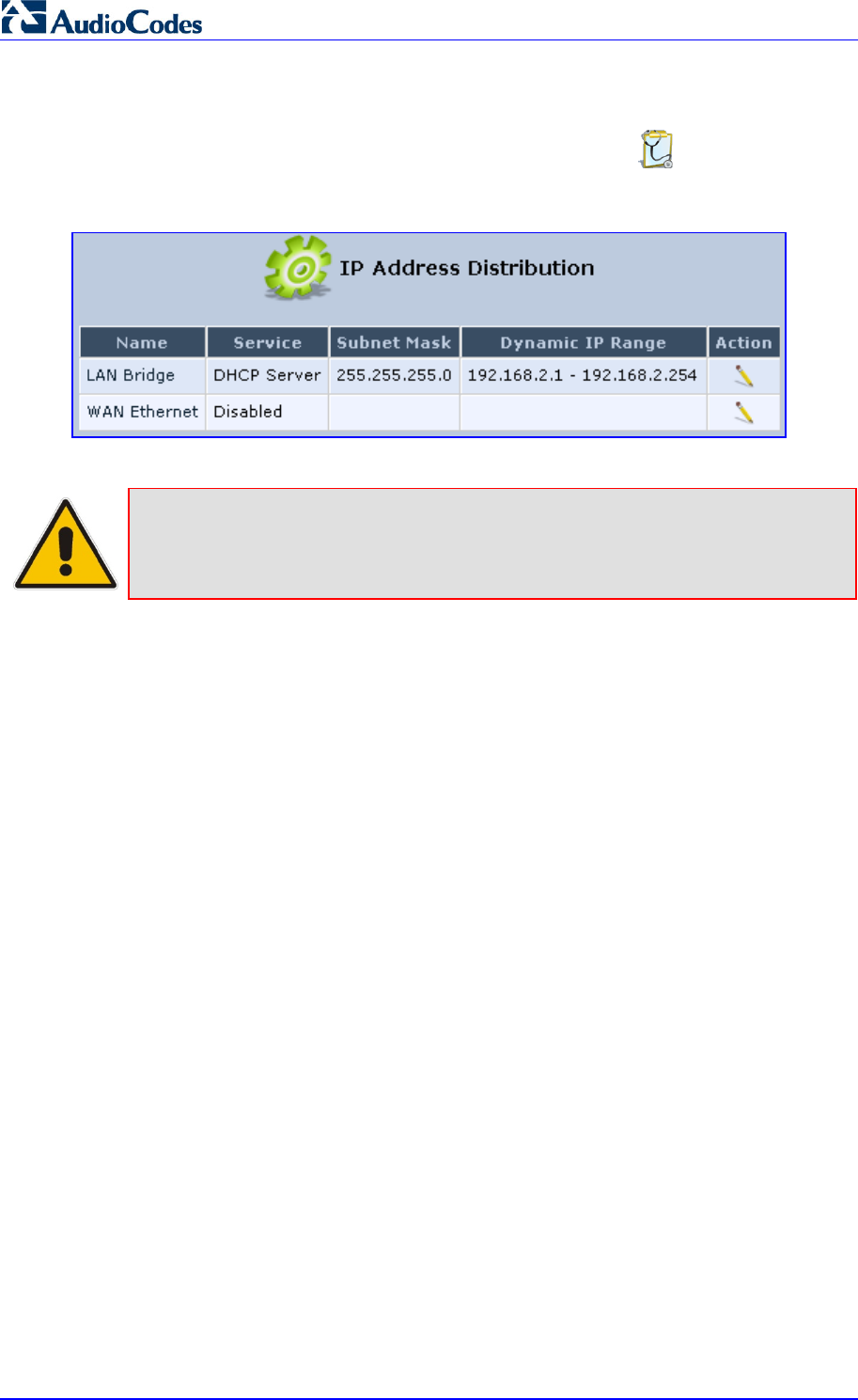
MP252 Multimedia Home Gateway 244 Document #: LTRT-23504
User's Manual
¾ To view services currently provided by the DHCP server:
In the 'Advanced' screen, click the IP Address Distribution icon; the 'IP Address
Distribution' screen appears.
Figure 15-1: DHCP Server Summary
Note: If the 'Service' column displays “Disabled”, then DHCP services are not being
provided to hosts connected to the network through that MP252 interface. This
means that MP252 does not assign IP addresses to these computers, which is
useful if you wish to work with static IP addresses only.
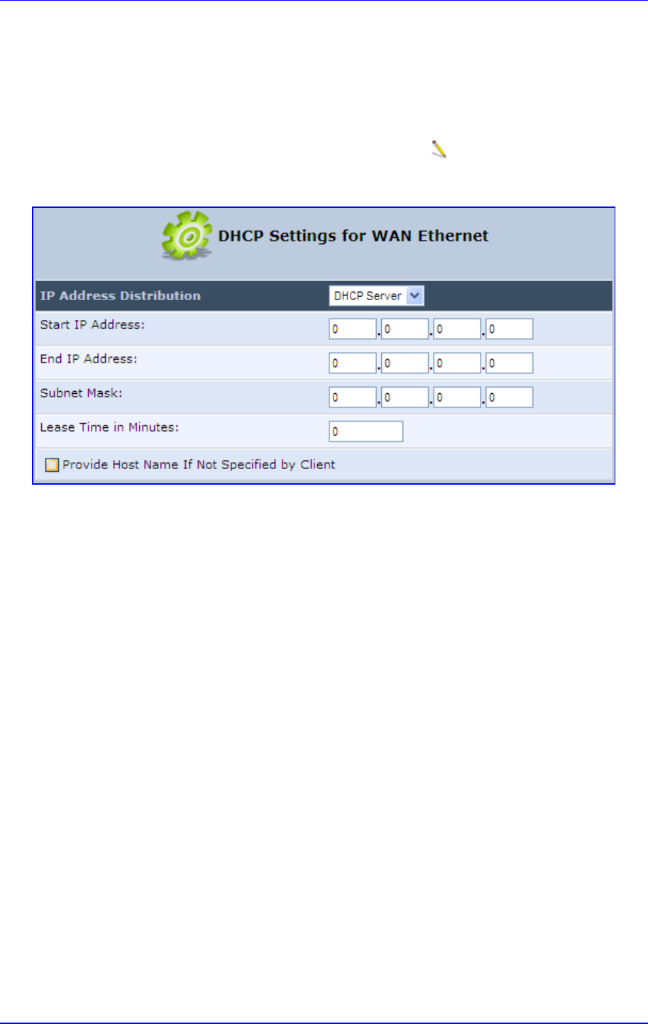
MP252 Multimedia Home Gateway 15. Advanced Networking Features
Version 3.4.0 245 June 2011
15.1.1 DHCP Server Parameters
The procedure below describes how to edit a service provided by the DHCP server.
¾ To edit the DHCP server settings for a device:
1. In the 'IP Address Distribution' screen, click the Edit icon corresponding to the entry
that you want to edit; the DHCP Server settings for this device are displayed.
Figure 15-2: DHCP Settings Screen
2. From the 'IP Address Distribution' drop-down list, select whether to disable the MP252
DHCP server, or enable DHCP (MP252 serves as a DHCP server or DHCP relay).
3. In the ‘Start IP Address’ and ‘End IP Address’ fields, define the IP address range. This
determines the number of hosts that may be connected to the network in this subnet.
The 'Start IP Address' field specifies the first IP address that may be assigned in this
subnet; the 'End IP Address' field specifies the last IP address in the range.
4. In the ‘Subnet Mask’ field, define the subnet to which an IP address belongs (e.g.,
255.255.0.0).
5. In the ‘Lease Time in Minutes’ field, define the time for which each device is assigned an
IP address by the DHCP server when it connects to the network. When the lease
expires, the server determines if the computer has disconnected from the network. If it
has, then the server may reassign this IP address to a newly-connected computer. This
feature ensures that IP addresses that are not in use become available for other
computers on the network.
6. Select the ‘Provide Host Name If Not Specified by Client’ check box to enable the
MP252 to assign clients a default name if they do not have a host name.
7. Click OK.
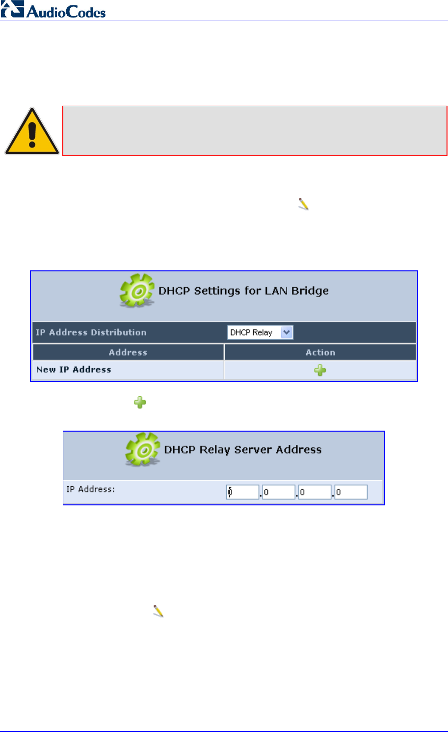
MP252 Multimedia Home Gateway 246 Document #: LTRT-23504
User's Manual
15.1.2 DHCP Relay Parameters
The MP252 can act as a DHCP relay if you want to dynamically assign IP addresses from a
DHCP server other than the MP252's DHCP server. .
Note: When implementing DHCP relay, you must configure the WAN of the MP252 to
operate in routing mode.
¾ To configure a device as a DHCP relay:
1. In the 'IP Address Distribution' screen, click the Edit icon corresponding to the entry
that you want to edit; the DHCP Server settings for this device are displayed.
2. From the 'IP Address Distribution' drop-down list, select the 'DHCP Relay' option; the
'DHCP Settings' screen appears.
Figure 15-3: DHCP Settings
3. Click the New icon; the 'DHCP Relay Server Address' screen appears.
Figure 15-4: DHCP Relay Server Address Screen
4. In the 'IP Address' field, enter the IP address of the DHCP server.
5. Click OK to save your changes.
6. Click OK once more in the 'DHCP Settings' screen.
7. Change MP252's WAN to operate in routing mode:
a. On the menu bar, click the Network Connections menu; the 'Network
Connections' screen appears.
b. Click the Edit icon corresponding to the WAN Ethernet connection; the 'WAN
Ethernet Properties' screen appears.
c. Click the Routing tab.
d. From the 'Routing Mode' drop-down list, select 'Route'.
e. Click OK to save the settings.
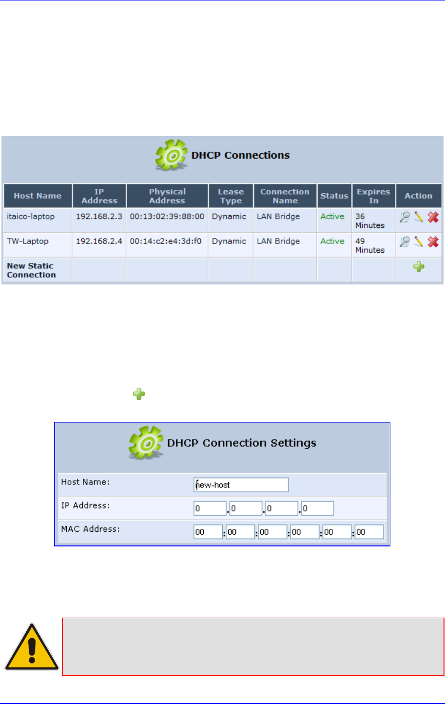
MP252 Multimedia Home Gateway 15. Advanced Networking Features
Version 3.4.0 247 June 2011
15.1.3 Viewing DHCP Clients
The procedure below describes how to view a list of hosts (computers) that are allocated IP
addresses by the DHCP server.
¾ To view a list of computers currently recognized by the DHCP server:
1. In the 'IP Address Distribution' screen, click the Connection List button; the 'DHCP
Connections' screen appears.
Figure 15-5: DHCP Connection Screen
15.1.4 Defining Static DHCP Clients
The procedure below describes how to define a static (fixed) IP address for a DHCP client.
¾ To define a DHCP client with a fixed IP address:
1. In the 'IP Address Distribution' screen, click the Connection List button; the 'DHCP
Connections' screen appears.
2. Click the New icon; the 'DHCP Connection Settings' screen appears.
Figure 15-6: DHCP Connection Settings Screen
3. In the 'Host Name' field, enter a host name for this connection.
4. In the 'IP Address' field, enter the fixed IP address to be assigned to the computer.
5. In the 'MAC Address' field, enter the MAC address of the computer's network card.
Note: A device's fixed IP address is actually assigned to the specific network card's
(NIC) MAC address installed on the LAN computer. If you replace this network
card then you must update the device's entry in the DHCP Connections list with
the new network card's MAC address.

MP252 Multimedia Home Gateway 248 Document #: LTRT-23504
User's Manual
6. Click OK to save the settings; the 'DHCP Connections' screen reappears displaying the
defined static connection. This connection can be edited or deleted.

MP252 Multimedia Home Gateway 15. Advanced Networking Features
Version 3.4.0 249 June 2011
15.2 DNS Server
The DNS Server icon allows you to manage the MP252 Domain Name System (DNS)
server. The DNS server does not require configuration. However, you can view the list of
computers known by the DNS, edit the host names or IP addresses of computers in the list,
or manually add a new computer to the list.
DNS provides a service that translates domain names into IP addresses and vice versa.
MP252's DNS server is an auto-learning DNS, which means that when a new computer is
connected to the network, the DNS server learns its name and automatically adds it to the
DNS table. Other network users may immediately communicate with this computer using
either its name or its IP address.
The MP252 DNS server also provides the following functionalities:
Shares a common database of domain names and IP addresses with the DHCP server.
Supports multiple subnets within the LAN simultaneously.
Automatically appends a domain name to unqualified names.
Allows new domain names to be added to the database using MP252's Web interface.
Permits a computer to have multiple host names.
Permits a host name to have multiple IPs (needed if a host has multiple network cards).
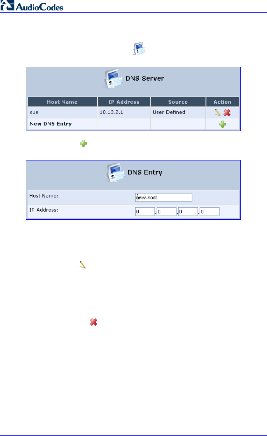
MP252 Multimedia Home Gateway 250 Document #: LTRT-23504
User's Manual
¾ To add a new host computer to the DNS table:
1. In the 'Advanced' screen, click the icon; the DNS table is displayed.
Figure 15-7: DNS Server
2. Click the New icon; the 'DNS Entry' screen appears.
Figure 15-8: DNS Entry
3. Enter the computer's host name and IP address.
4. Click OK to save your changes.
¾ To edit the host name or IP address of an entry:
1. Click the Edit icon corresponding to the host that you want to edit; the 'DNS Entry'
screen appears.
2. If the host was manually added to the DNS Table, you can modify its host name and/or
IP address. If it wasn't, you can only modify its host name.
3. Click OK to save your changes.
¾ To remove a host from the DNS table:
Click the Remove icon corresponding to the host that you want to delete; the entry is
removed from the table.
15.3 Dynamic DNS
The Dynamic DNS (DDNS) feature allows you to alias a dynamic IP address to a static
hostname, allowing your computer to be more easily accessible from various locations on the
Internet. Typically, when you connect to the Internet, your ITSP assigns an unused IP
address from a pool of IP addresses, and this address is used only for the duration of a
specific connection. Dynamically assigning addresses extends the usable pool of available
IP addresses, whilst maintaining a constant domain name.
When using the DDNS service, each time the IP address provided by your ITSP changes,
the DNS database changes accordingly to reflect the change. In this way, even though your
IP address changes often, your domain name remains constant and accessible.
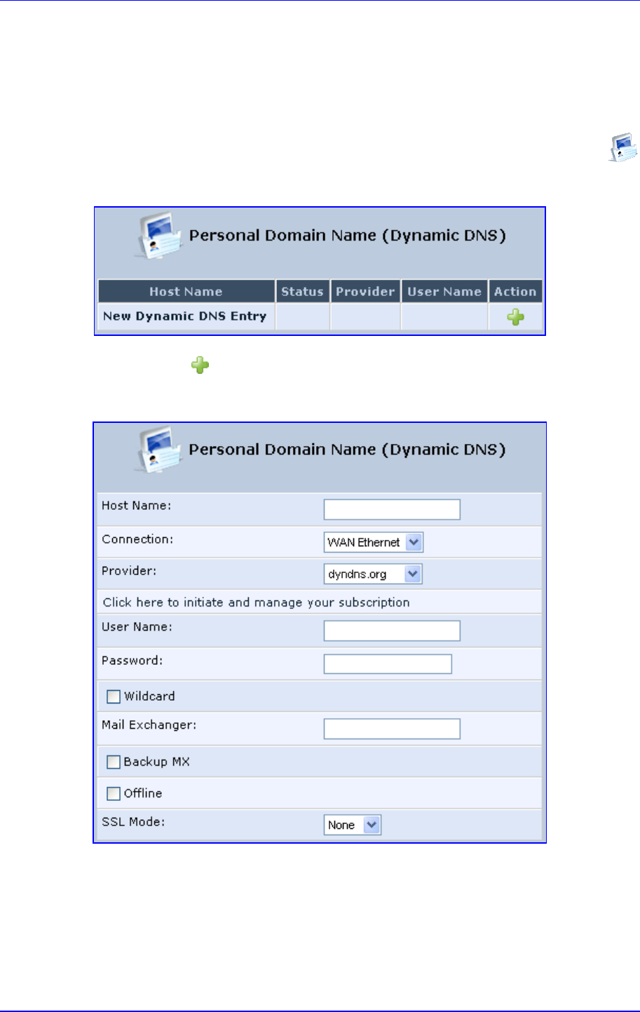
MP252 Multimedia Home Gateway 15. Advanced Networking Features
Version 3.4.0 251 June 2011
To be able to use the Dynamic DNS (DDNS) feature, you must first open a free DDNS
account at http://www.dyndns.org/account/create.html. When applying for an account, you
need to specify a user name and password. Have them readily available when customizing
MP252's DDNS support. For detailed information on DDNS, see http://www.dyndns.org.
¾ To open a dynamic DNS account:
1. In the 'Advanced' screen, click the Personal Domain Name (Dynamic DNS)
icon; the 'Personal Domain Name (Dynamic DNS)' screen appears.
Figure 15-9: Personal Domain Name (Dynamic DNS) Screen
2. Click the New icon to add a new connection; the 'Personal Domain Name (Dynamic
DNS)' screen appears.
Figure 15-10: Personal Domain Name (Dynamic DNS) - Adding
3. In the ‘Host Name’ field, enter your full DDNS domain name.
4. From the ‘Connection’ drop-down list, select the connection to which you want to couple
the DDNS service. The DDNS service uses only the selected device, unless failover is
enabled. In this case, the failed-to device is used instead (assuming its route rules
consent), until the chosen device is up again. In a single WAN scenario, this field
appears as static text (non-configurable). This is applicable if you have multiple WAN
devices.

MP252 Multimedia Home Gateway 252 Document #: LTRT-23504
User's Manual
5. From the ‘Provider’ drop-down list, select your DDNS service provider and then click the
link Click here to initiate and manage your subscription to open the selected
provider's account creation Web page. For example, if you select ‘dyndns.org’, the
following page opens: http://www.dyndns.com/account.
6. In the ‘User Name’ and ‘Password’ fields, enter your DDNS user name and password,
respectively.
7. To enable use of special links (such as such as www.<your host>.dyndns.org), select
the ‘Wildcard’ check box.
8. In the ‘Mail Exchanger’ field, enter your mail exchange server address to redirect all
e-mails arriving at your DDNS address to your mail server.
9. To designate the mail exchange server as a backup server, select the ‘Backup MX’
check box.
10. To temporarily take your site offline (i.e., prevent traffic from reaching your DDNS
domain name), select the ‘Offline’ check box. This redirects DNS requests to an
alternative, predefined URL. The availability of this feature depends on your DDNS
account's level of service. The redirection URL must be configured through the account
as well.
11. From the ‘SSL Mode’ drop-down list, select the certificate validation method used by
MP252 to validate the DDNS server's certificate upon secured connection to DDNS
using HTTPS:
• None: The server's certificate is not validated.
• Chain: Validates the entire certificate chain. When selecting this option, the screen
refreshes, displaying the 'Validate Time' drop-down list for selecting whether or not
to validate the certificate's expiration time ('Ignore' or 'Check' respectively). If the
certificate has expired, the connection terminates immediately.
• Direct: Ensures that the server's certificate is directly signed by the root certificate.
This option also provides the 'Validate Time' drop-down list for validation of the
certificate's expiration time, as described above.
12. Click OK.
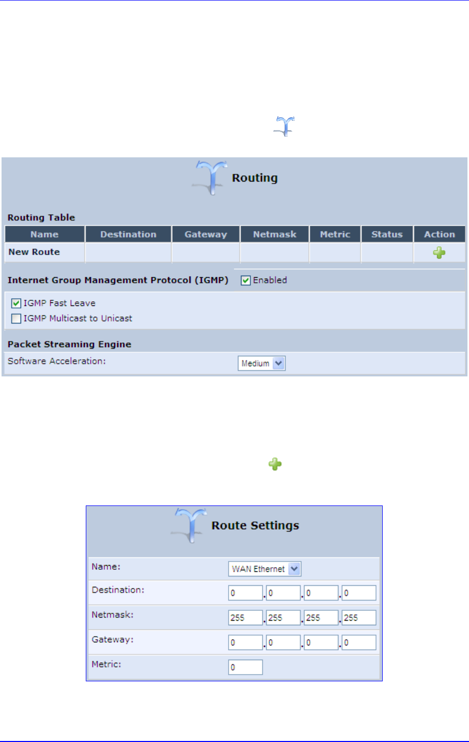
MP252 Multimedia Home Gateway 15. Advanced Networking Features
Version 3.4.0 253 June 2011
15.4 Routing
This section describes how to configure routing rules and enable routing protocols. These
are configured in the ‘Routing’ screen, as described below.
¾ To access the Routing screen:
In the 'Advanced' screen, click the Routing icon; the 'Routing' screen appears.
Figure 15-11: Routing Rules
15.4.1 Managing Routing Table Rules
The procedure below describes how to add routing rules.
¾ To add routing tables:
1. In the 'Advanced' screen, click the New icon in the Routing Table; the 'Route
Settings' screen appears.
Figure 15-12: Route Settings Screen
2. From the ‘Name’ drop-down list, select the network device for which you want to add a
routing rule.

MP252 Multimedia Home Gateway 254 Document #: LTRT-23504
User's Manual
3. In the ‘Destination’ field, enter the destination host, subnet address, network address, or
default route. The destination for a default route is “0.0.0.0”.
4. In the ‘Netmask’ field, enter the network mask that used in conjunction with the
destination to determine when a route is used.
5. In the ‘Gateway’ field, enter the MP252's IP address.
6. In the ‘Metric’ field, enter the measurement of the preference of a route. Typically, the
lowest metric is the most preferred route. If multiple routes exist to a given destination
network, the route with the lowest metric is used.
7. Click OK to save your settings.
15.4.2 Routing Protocols
MP252 supports IGMP multicasting, which allows hosts connected to a network to be
updated whenever an important change occurs in the network. A multicast is simply a
message that is sent simultaneously to a pre-defined group of recipients. When you join a
multicast group you receive all messages addressed to the group, similar to an e-mail
message sent to a mailing list.
IGMP multicasting enables UPnP capabilities over wireless networks and may also be useful
when connected to the Internet through a router. When an application running on a computer
in the home network sends out a request to join a multicast group, MP252 intercepts and
processes the request. If MP252 is set to 'Minimum Security', no further action is required.
However, if MP252 is set to 'Typical Security' or 'Maximum Security', you must add the
group's IP address to MP252's 'Multicast Groups' screen. This allows incoming messages
addressed to the group to pass through the MP252 firewall and on to the correct LAN
computer.
¾ To configure routing protocols:
1. In the 'Advanced' screen, under the Internet Group Management Protocol (IGMP)
group, do the following:
a. Select the 'Enabled' check box to enable IGMP multicasting.
b. Select the ‘IGMP Fast Leave' check box if you want MP252 to stop forwarding
traffic to a host that is the only subscriber, immediately upon request (without query
delay).
c. Select the 'IGMP Multicast to Unicast' check box to enable MP252 to convert the
incoming multicast data stream into unicast format to route it to the specific LAN
host that requested the data. In this way, MP252 prevents flooding the rest of the
LAN hosts with irrelevant multicast traffic.
2. Under the Packet Streaming Engine group, from the ‘Software Acceleration’
drop-down list, select the packet flow speed:
• None: Packet Streaming Engine (PSE) is disabled
• Medium: PSE is active (recommended)
• High: PSE traffic is prioritized over other traffic
3. Click OK.
15.5 PPPoE Relay
PPPoE relay enables MP252 to relay packets on PPPoE connections while keeping its
designated functionality for any additional connections.
¾ To enable PPPoE relay:

MP252 Multimedia Home Gateway 15. Advanced Networking Features
Version 3.4.0 255 June 2011
1. In the 'Advanced' screen, click the PPPoE Relay icon; the 'PPPoE Relay' screen
appears.
Figure 15-13: PPPoE Relay Screen
2. Select the 'Enabled' check box.
3. Click OK.
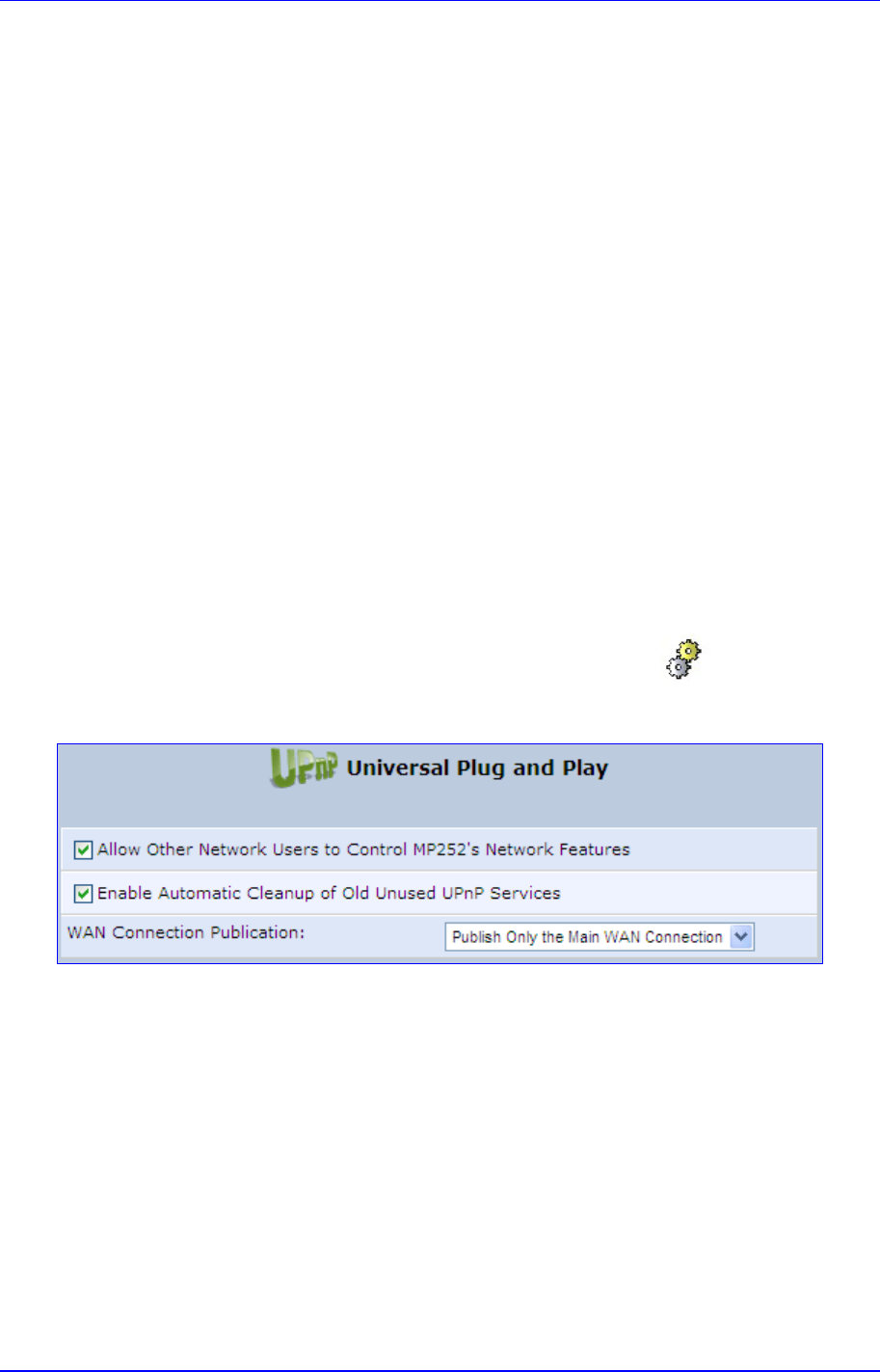
Version 3.4.0 257 July 2011
MP252 Multimedia Home Gateway 16. Home Media
16 Home Media
16.1 Universal Plug and Play
Universal Plug-and-Play (UPnP) is a networking architecture that provides compatibility
among networking equipment, software, and peripherals. UPnP-enabled products can
seamlessly connect and communicate with other UPnP-enabled devices without the need for
user configuration, centralized servers, or product-specific device drivers. This technology
leverages existing standards and technologies, including TCP/IP, HTTP 1.1 and XML,
facilitating the incorporation of UPnP capabilities into a wide range of networked products for
the home.
UPnP technologies are rapidly adopted and integrated into widely-used consumer products
such as Windows XP. Therefore it is critical that today's Residential Gateways be
UPnP-compliant. Your MP252 is at the forefront of this development, offering a complete
software platform for UPnP devices. This means that any UPnP-enabled control point (client)
can dynamically join the network, obtain an IP address and exchange information about its
capabilities and those of other computers on the network. They can subsequently
communicate with each other directly, thereby further enabling peer-to-peer networking. And
this all happens automatically, providing a truly zero-configuration network.
16.1.1 Enabling UPnP on MP252
The procedure below describes how to enable the UPnP feature on MP252.
¾ To enable UPnP:
1. In the 'Advanced' screen, click the Universal Plug and Play icon; the 'Universal
Plug and Play' screen appears.
Figure 16-1: Advanced - Universal Plug n Play
2. Select the ‘Allow Other Network Users to Control MP252’s Network Features’ to enable
the UPnP feature. This allows you to define UPnP services on any of the LAN hosts.
3. Select the ‘Enable Automatic Cleanup of Old Unused UPnP Services’ to enable
automatic cleanup of invalid rules. This feature checks the validity of all UPnP services
every five minutes, and removes old and obsolete services, unless a user-defined rule
depends on them.
4. From the ‘WAN Connection Publication’ drop-down list, select which WAN information
is published by MP252. By default, MP252 publishes only its main WAN connection,
which is controllable by UPnP entities. However, you may select the 'Publish All WAN
Connections' option if you wish to grant UPnP control over all of MP252’s WAN
connections.
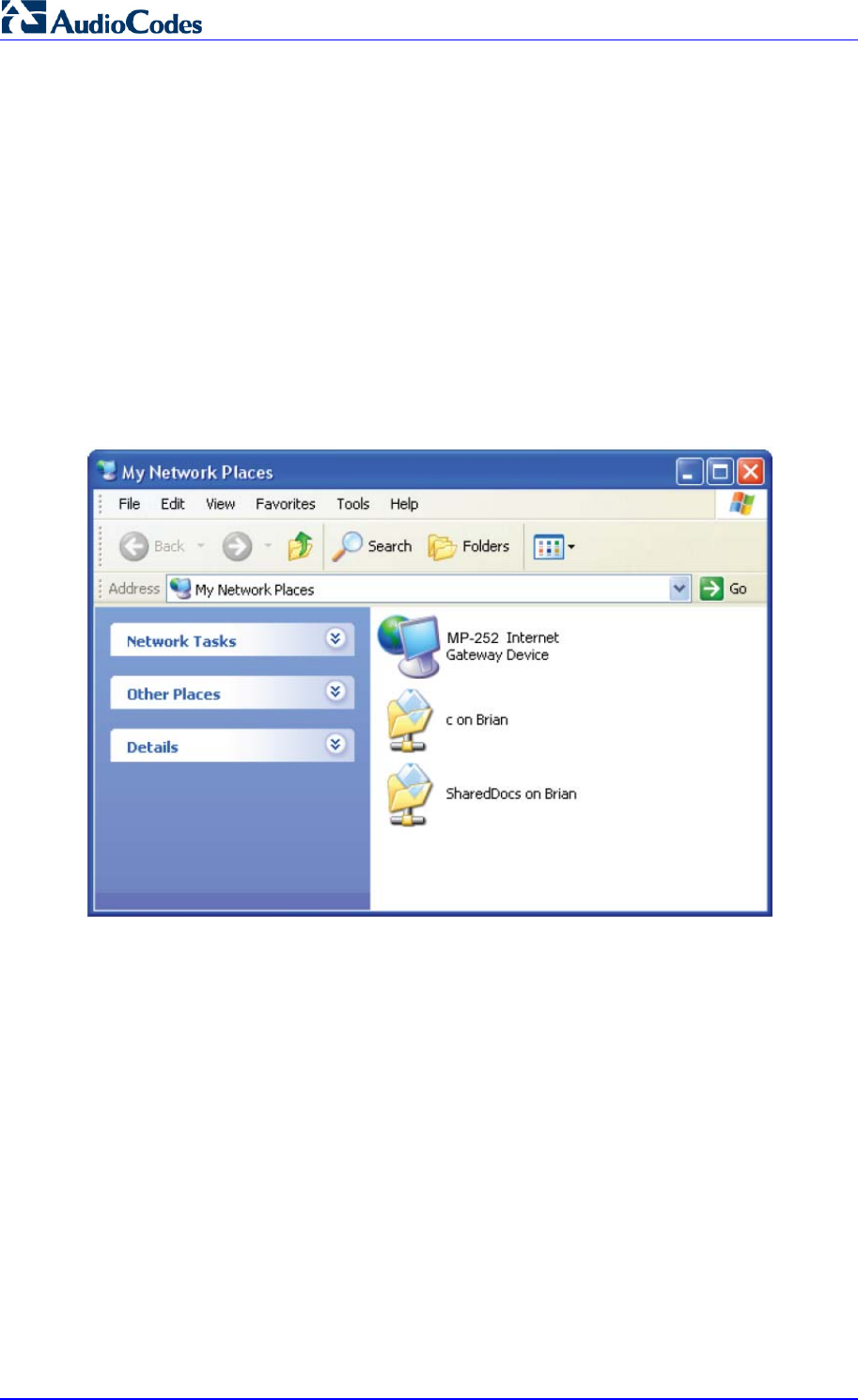
MP252 Multimedia Home Gateway 258 Document #: LTRT-23504
User's Manual
16.1.2 Adding UPnP-enabled PC to Home Network
If your computer is running an operating system that supports UPnP such as Windows XP,
you can add the computer to your home network and access the Web-based Management
directly from Windows.
¾ To add a UPnP-enabled computer to the home network:
Connect the PC to MP252; the PC automatically recognizes and adds to the home
network. MP252 is added to 'My Network Places' as the Internet Gateway Device and
allows configuration via a standard Windows interface. A message appears on the
notification area of the taskbar notifying that the PC has been added to the network.
¾ To access the Web-based management directly from Windows:
1. Open the 'My Network Places' window by double-clicking its desktop icon.
Figure 16-2: My Network Places
2. Double-click the MP252 Internet Gateway Device icon. The MP252 Web interface
‘Login’ screen appears in a browser window. This method is similar to opening a
browser window and typing in '192.168.1.1'.
16.1.3 Monitoring Connection between MP252 and Internet
The procedure below describes how to monitor the status of the connection between MP252
and the Internet.
¾ To monitor the status of the connection between MP252 and the Internet:
1. Open the 'Network Connections' control panel.
2. Double-click the Internet Connection icon. The 'Internet Connection Status' window
appears:
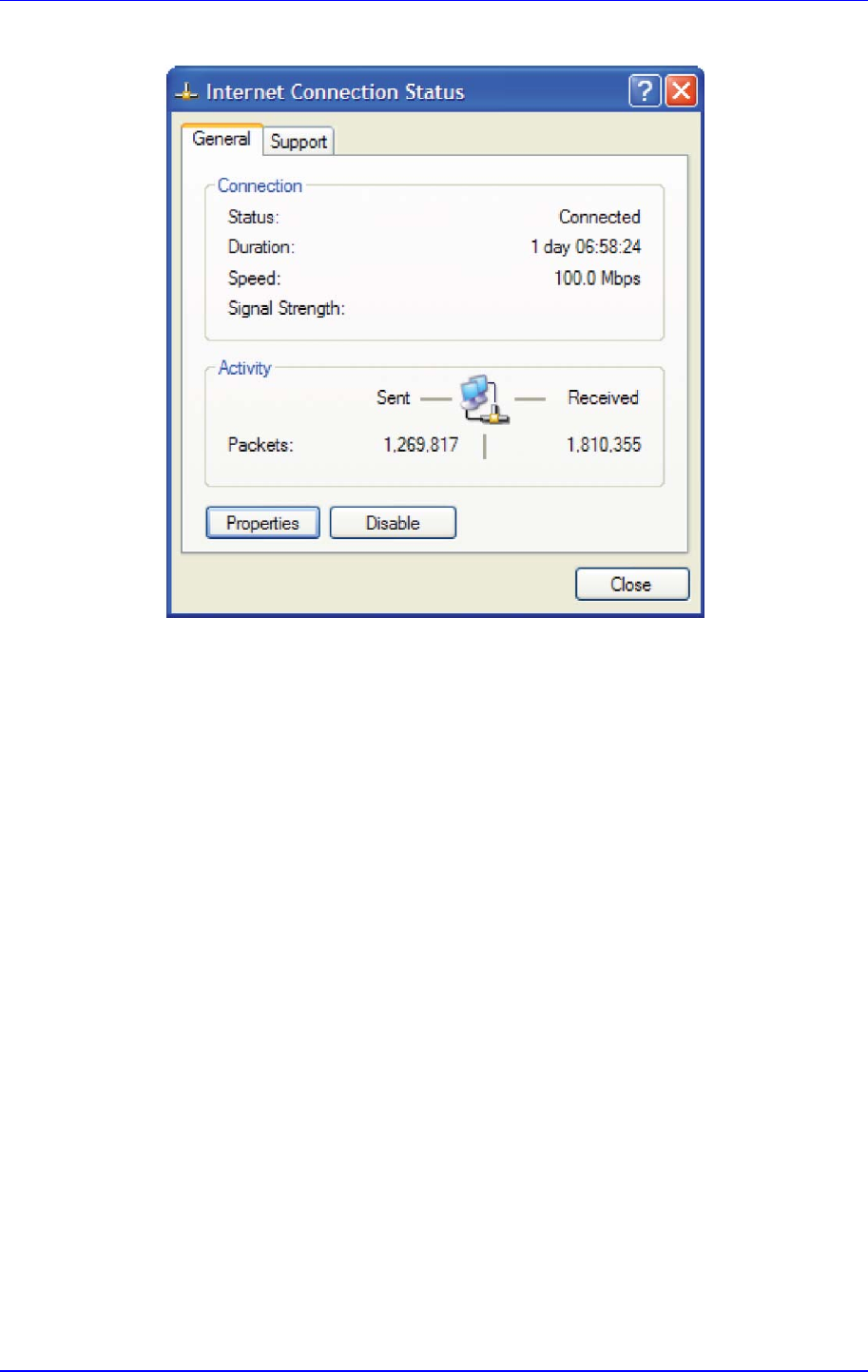
MP252 Multimedia Home Gateway 16. Home Media
Version 3.4.0 259 June 2011
Figure 16-3: Internet Connection Status
16.1.4 Making Local Services available to PCs on Internet
You can make services provided by computers in the home network available to computers
on the Internet. For example, you may designate a PC in your home network to act as a Web
server, allowing computers on the Internet to request pages from it. Or a game that you want
to play over the Internet may require that specific ports be opened to allow communication
between your PC and other players.
¾ To make local services available to computers on the Internet:
1. Open the 'Network Connections' control panel.
2. Right-click 'Internet Connection', and then choose Properties; The 'Internet Connection
Properties' window appears.
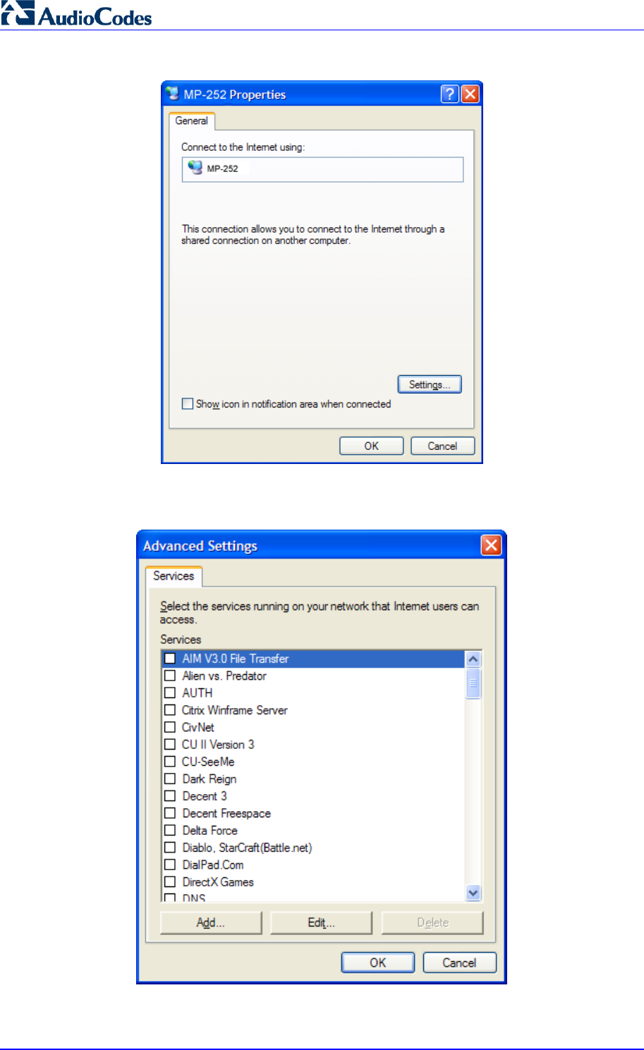
MP252 Multimedia Home Gateway 260 Document #: LTRT-23504
User's Manual
Figure 16-4: Internet Connection Properties
3. Click the Settings button; the 'Advanced Settings' window.
Figure 16-5: Advanced Settings
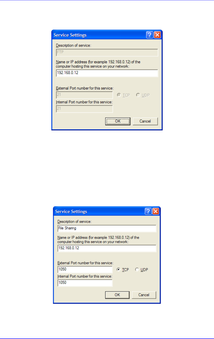
MP252 Multimedia Home Gateway 16. Home Media
Version 3.4.0 261 June 2011
4. Select a local service that you would like to make available to computers on the Internet;
the 'Service Settings' window automatically appears.
Figure 16-6: Service Settings
5. Enter the local IP address of the computer that provides this service and then click OK.
6. Select other services as desired and repeat the previous step for each.
7. Click OK to save the settings.
¾ To add a local service that is not listed in the 'Advanced Settings'
window:
1. Follow steps 1-3 above.
2. Click the Add button; the 'Service Settings' window appears.
Figure 16-7: Service Settings – Add Service
3. Complete the fields as indicated in the window.
4. Click OK to close the window and return to the 'Advanced Settings' window; the service
is selected.

MP252 Multimedia Home Gateway 262 Document #: LTRT-23504
User's Manual
5. Click OK to save the settings.
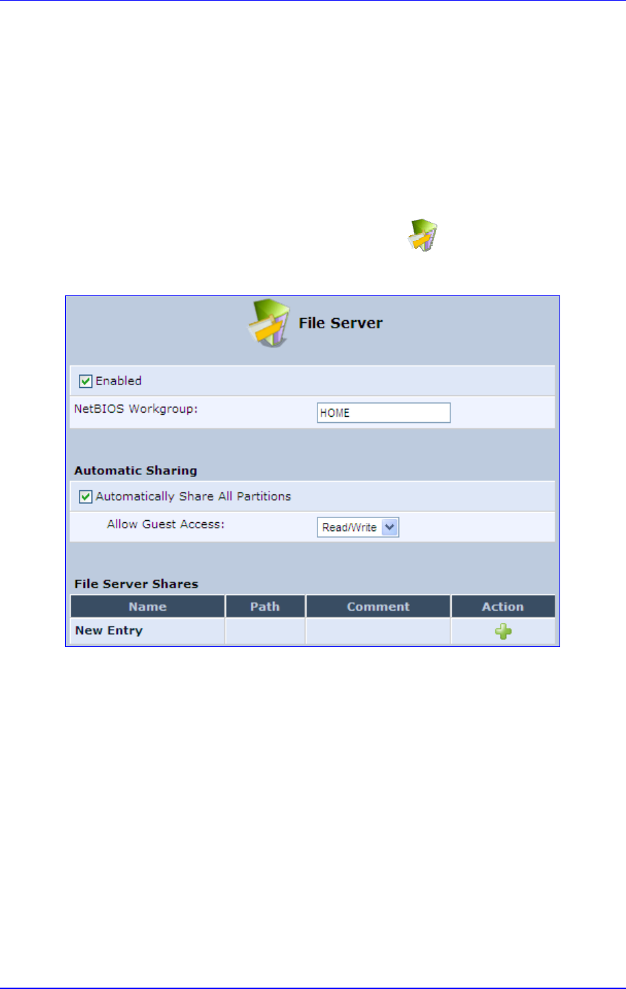
MP252 Multimedia Home Gateway 17. Add-On Servers and Disk Management
Version 3.4.0 263 June 2011
17 Add-On Servers and Disk Management
17.1 External File Server
MP252 provides a file server utility, allowing you to perform various tasks on your files, such
as manage file server shares and define access control lists. The file server utility
complements MP252’s disk management.
¾ To configure the file server:
1. In the 'Advanced' screen, click the File Server icon; the screen File Server'
opens.
Figure 17-1: File Server Screen
2. Configure the following:
• Enabled: Select or clear this check box to enable or disable this feature.
• NetBIOS Workgroup: MP252 workgroup name that is displayed in the Windows
network map of LAN hosts.
• Automatic Sharing:
♦ Automatically Share All Partitions: A partitioned storage device connected
to MP252 is automatically displayed and shared by all LAN computers. This
feature is enabled by default.
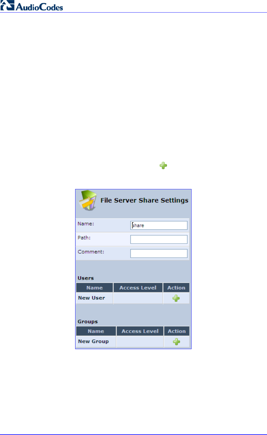
MP252 Multimedia Home Gateway 264 Document #: LTRT-23504
User's Manual
♦ Allow Guest Access: From the drop-down list, select a permission level,
according to which the LAN users access the share:
9 Read/Write: Every LAN user can read and write the shared files without
authentication.
9 Read Only: Every LAN user can only read the shared files.
9 Disabled: LAN users must authenticate themselves to access the share.
They can use the share according to their permissions defined in the
'User Settings' screen.
• File Server Shares: Define file shares on your disk partitions, as described in the
following sections.
17.1.1 Automatic File Sharing
By default, all partitions are automatically shared and displayed.
¾ To share specific directories or partitions:
1. Clear the 'Automatically Share All Partitions' check box, and then click Apply. The list of
all automatically shared partitions disappears.
2. In the ‘File Server Shares’ table, click New icon to define a new share; the 'File
Server Share Settings' screen appears.
Figure 17-2: File Server Share Settings Screen
3. Enter the share's name (default is “share”), path, and (optionally) comment. The share's
name is not case sensitive. Even if entered in upper-case letters, the name is displayed
in lower case after saving the setting.
4. Associate a user or group of users with the share to grant them access to the shared
files, by clicking the New User or New Group link in the Users or Groups table. Note
that the user’s settings must have the ‘Microsoft File and Printer Sharing Access’ check
box selected under the 'Permissions' section (see ‘Configuring Users’ on page 40); the
‘User’ screen appears:
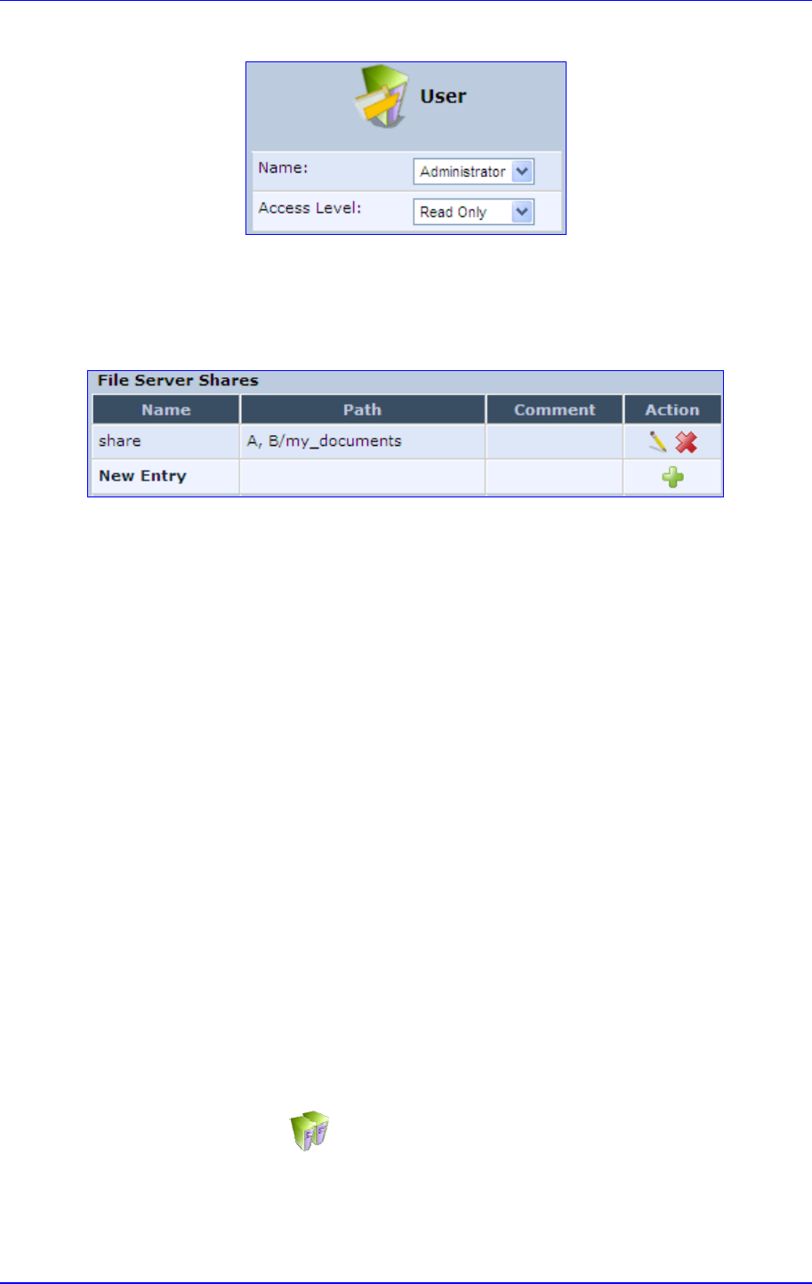
MP252 Multimedia Home Gateway 17. Add-On Servers and Disk Management
Version 3.4.0 265 June 2011
Figure 17-3: User Screen
d. From the ‘Name’ drop-down list, select the user name and the allowed access.
e. Click OK.
5. Click OK to save the settings. The 'File Server' screen appears, displaying the share.
Figure 17-4: File Server Screen with the Share
Click the share's name to view its content. The screen refreshes as the share is accessed
This screen enables you to modify and view the content of your file share. In the upper
section of this screen, you can modify your file share by adding files or directories to it. Use
the drop-down list to select an action:
Upload a File: Uploads a file to the share. The screen refreshes - enter the location of
the file to upload, or click the Browse button to browse for the file. Click the Upload
button to upload the file.
Upload a Directory: You can also upload an entire directory of files, by performing the
following:
a. Create a tarball archive out of the target directory.
b. Enter the location of the archive, or click the Browse button to browse to its
location.
c. Click the Upload button to upload the archive.
Create a new Directory: You can create a new directory by simply typing its name and
clicking Go.
Paste from Clipboard: This option appears only after using the 'Copy to Clipboard'
option to copy a directory or file from one directory to another.
The lower section of the screen displays your share's content. You can click the different
directory names to access them or you can download, rename, copy or remove the
directories using the standard action icons.
17.2 Disk Management
The Disk Management icon allows you to configure disk management. MP252 can
operate as a disk manager for either internal disks connected through IDE, or external
storage devices connected through USB or FireWire. Your home-network's LAN devices can
share this storage device as a mapped network drive and exchange information without
directly accessing each other. The Web interface provides disk management utilities such as
partitioning and formatting.
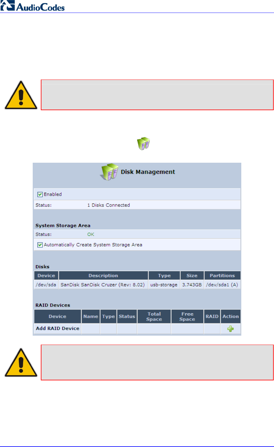
MP252 Multimedia Home Gateway 266 Document #: LTRT-23504
User's Manual
An internal disk or a connected storage device appears in the Network Map (see Section 5
on page 50). You can view information about the disk by clicking its icon.
The device supports storage devices with FAT32, NTFS, and Linux EXT2/3 file systems.
These file systems have different sharing and security settings. If the connected storage
device or at least one of its partitions has the NTFS file system, a message appears in the
'Disk Management’ screen appears.
Note: MP252 based on the Conexant Solos, Mindspeed Malindi2 or Freescale
platform allows both read and write access to an NTFS partition.
¾ To configure disk management:
1. In the 'Advanced' screen, click the icon; the ‘Disk Management' screen appears.
Figure 17-5: Disk Management Screen
Note: To define a system storage area, the disk or at least one of its partitions should
be formatted. This storage area holds the data used by the MP252’s services.
For security, it is recommended to format the disk or its partition in the EXT2 or
EXT3 file system, although FAT32 is supported as well.
2. To enable disk management, select the ‘Enabled’ check box.
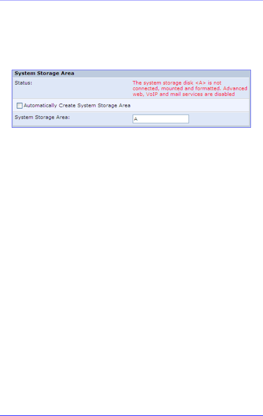
MP252 Multimedia Home Gateway 17. Add-On Servers and Disk Management
Version 3.4.0 267 June 2011
3. To set the first identified formatted partition as the location of the system storage area,
select the ‘Automatically Create System Storage Area’ check box. This setting is valid
until the storage device is disconnected. When reconnected, MP252 may select another
partition for this purpose. To define the system storage area manually, clear this check
box. The screen refreshes, displaying the 'System Storage Area' field in which you must
enter the partition's letter. In this scenario, the setting remains permanent even after the
storage device is disconnected and reconnected afterwards.
Figure 17-6: Manually Defining System Storage Area
4. In the Disks table, you can view a list of your connected storage devices. The 'Device'
column displays the names MP252 grants connected devices. Click this link to view the
device's 'Disk Information' screen. If a disk is partitioned, the 'Partitions' column displays
its partition names. If the partitions are formatted, their name includes a letter.
5. In the RAID Devices table, you can view the RAID devices (if configured).
17.2.1 Disk Partitions
This section describes how to configure partition and format storage devices.
17.2.1.1 Connecting a Mass Storage Device
To set up a file server that is shared by all LAN computers, you need to connect a mass
storage device (e.g. disk-on-key or hard drive) to the USB port on your MP252. A mass
storage device must first be partitioned and formatted. If your device is already partitioned, it
is recommended that you delete its partitions before proceeding, as a partition can only be
added on unallocated disk space.
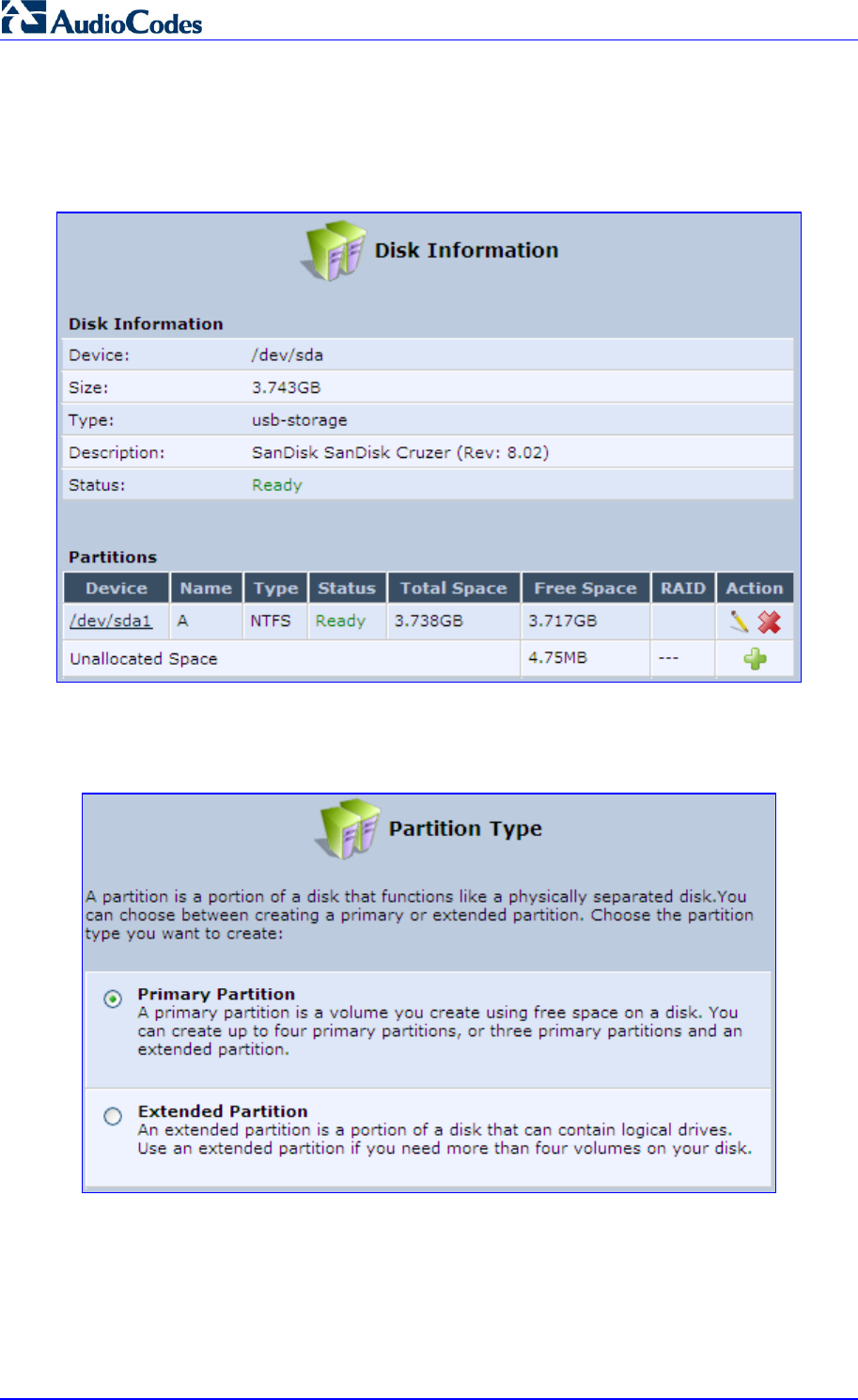
MP252 Multimedia Home Gateway 268 Document #: LTRT-23504
User's Manual
¾ To add a Windows formatted partition:
1. In the Disks table in the 'Disk Management' screen, click the disk device link. The 'Disk
Information' screen appears.
Figure 17-7: Disk Information
2. In the 'Partitions' table, click the Add New Partition icon; the 'Partition Type' screen
appears.
Figure 17-8: Partition Type
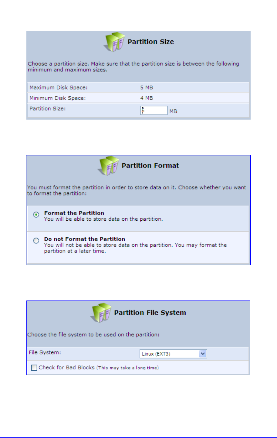
MP252 Multimedia Home Gateway 17. Add-On Servers and Disk Management
Version 3.4.0 269 June 2011
3. Select 'Primary Partition', and then click Next; the 'Partition Size' screen appears.
Figure 17-9: Partition Size
4. Enter a volume for the new partition (in mega bytes), and then click Next; the 'Partition
Format' screen appears.
Figure 17-10: Partition Format
5. Select 'Format the Partition', and then click Next; the 'Partition File System' screen
appears.
Figure 17-11: Partition File System
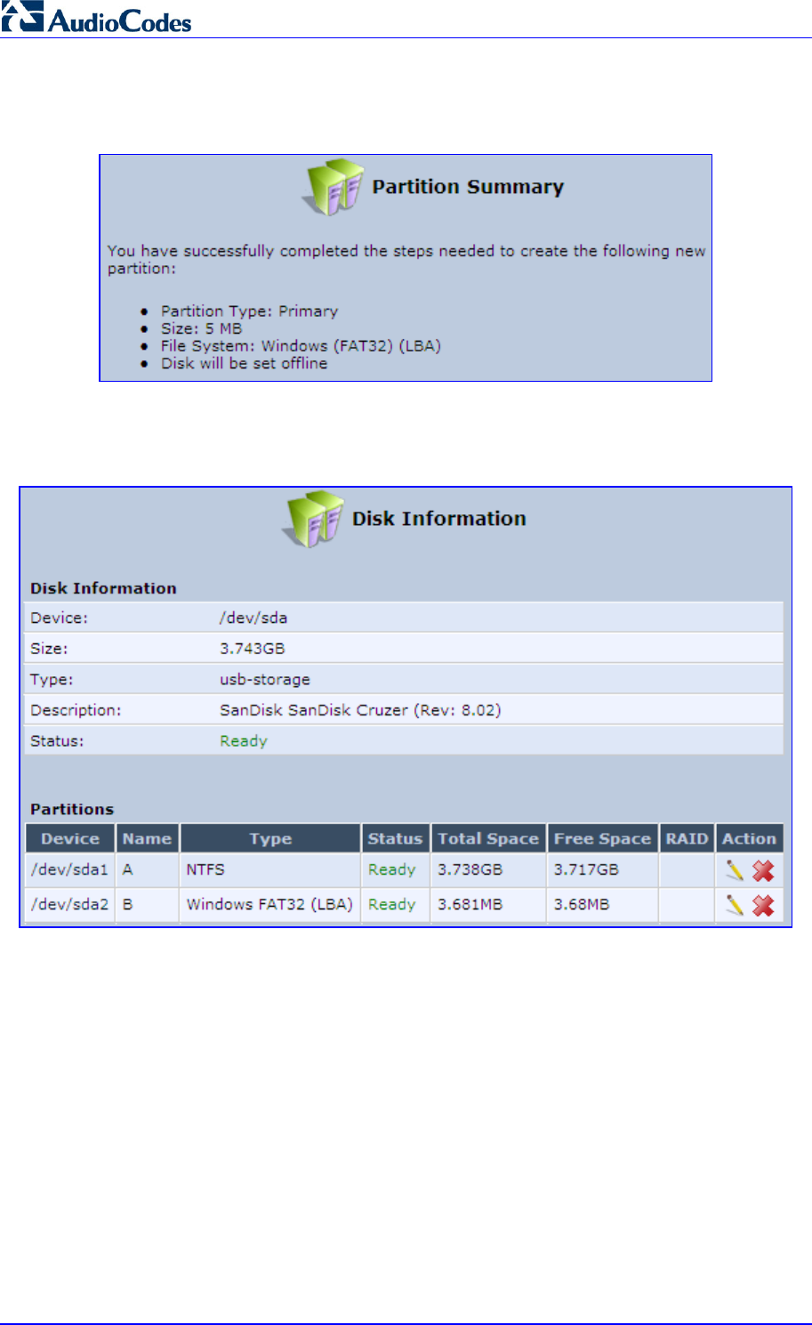
MP252 Multimedia Home Gateway 270 Document #: LTRT-23504
User's Manual
6. Select 'Windows (FAT32) (LBA)' as the file system for the partition and then click Next;
the 'Partition Summary' screen appears.
Figure 17-12: Partition Summary
7. Click Finish to create the new partition; the 'Disk Information' screen reappears,
refreshing as the partition formatting progresses, until the status changes to 'Ready'.
Figure 17-13: Formatting Complete – Partition Ready
The new partition names are designated as "A", "B" etc, and appear under the 'Name'
column of the 'Partitions' section.
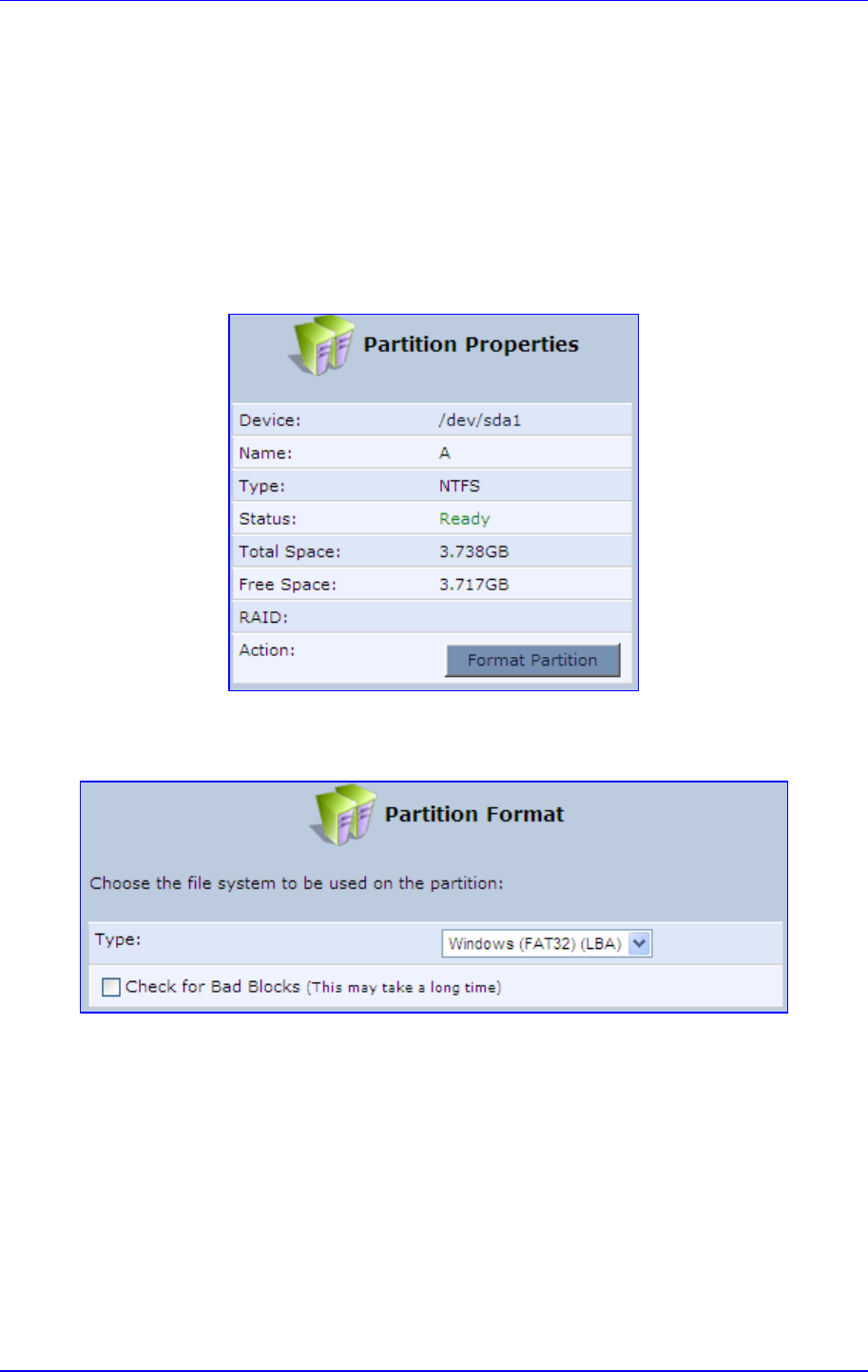
MP252 Multimedia Home Gateway 17. Add-On Servers and Disk Management
Version 3.4.0 271 June 2011
17.2.1.2 Formatting a Partition
A partition can be formatted in EXT2, EXT3, FAT32 and NTFS file systems.
¾ To partition a disk:
1. In the Disks table in the 'Disk Management' screen, click the disk device link; the 'Disk
Information' screen appears.
2. In the 'Partitions' table, click the Edit Partition icon of the partition you would like to edit;
the 'Partition Properties' screen appears.
Figure 17-14: Partition Properties
3. Click Format Partition; the 'Partition Format' screen appears.
Figure 17-15: Partition Format
4. Select a file system for the partition and then click Next. A warning screen appears,
alerting you that all the data on the partition will be lost.
5. Click OK to format the partition; the screen refreshes as the partition formatting
progresses. When the format is complete, the status will change to 'Ready'.
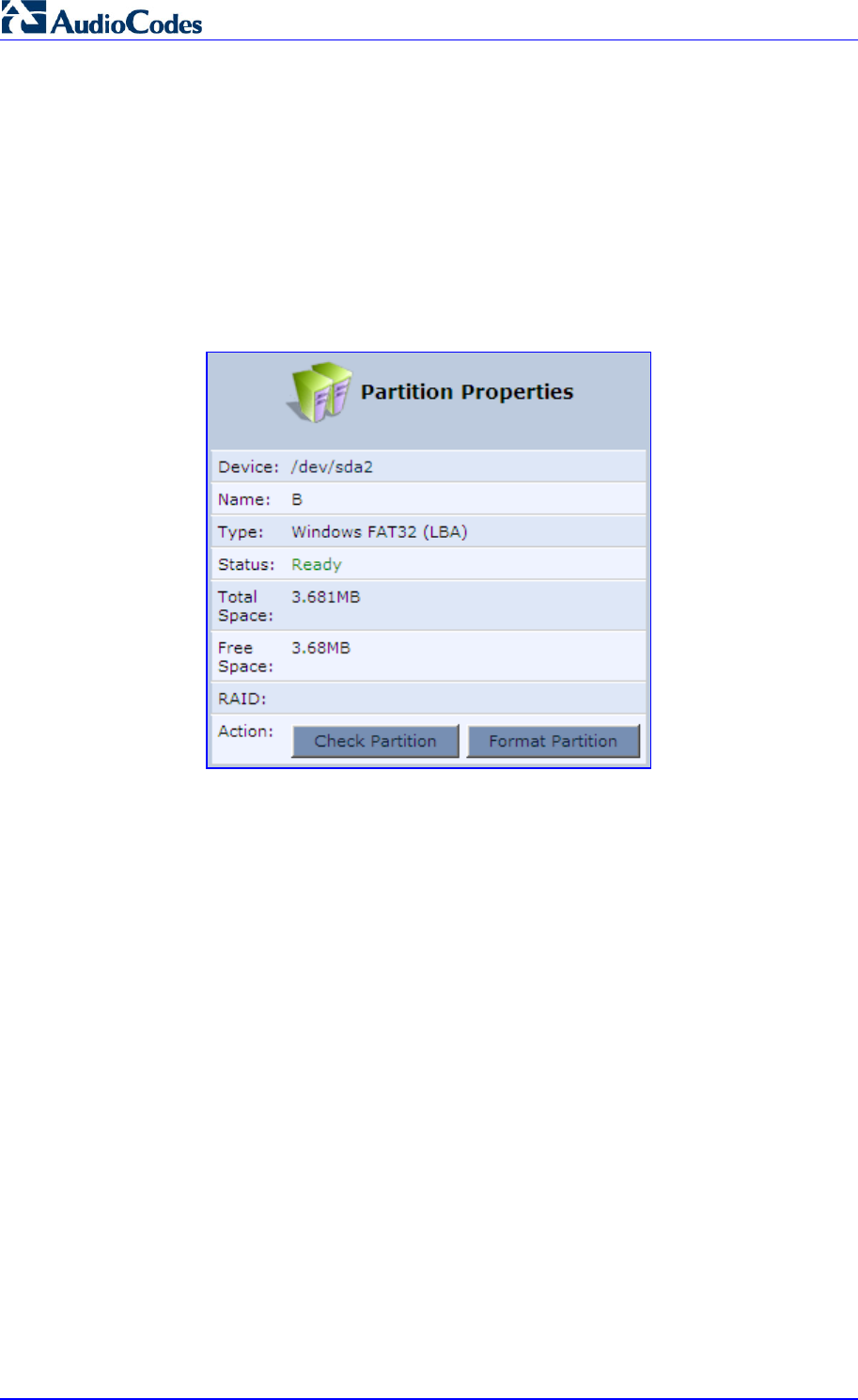
MP252 Multimedia Home Gateway 272 Document #: LTRT-23504
User's Manual
17.2.1.3 Checking a Partition
The procedure below describes how to check a partition.
¾ To check a partition:
1. In the Disks table in the 'Disk Management' screen, click the disk device link; the 'Disk
Information' screen appears.
2. In the 'Partitions' section, click the Edit Partition icon of the partition you would like to
check; the 'Partition Properties' screen appears.
Figure 17-16: Partition Format
3. Click Check Partition; a warning screen appears, alerting you that the partition will be
set to offline.
4. Click OK; the screen refreshes as the partition checking progresses. When the check is
complete, the status changes to 'Ready'.
17.2.1.4 Deleting a Partition
The procedure below describes how to delete a partition.
¾ To delete a partition:
1. In the Disks table in the 'Disk Management' screen, click the disk device link; the 'Disk
Information' screen appears.
2. In the 'Partitions' section, click the Remove Partition icon of the partition you would like
to delete; a warning screen appears, alerting you that all the data on the partition will be
lost.
3. Click OK to delete the partition.
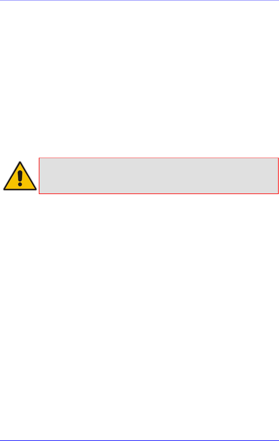
MP252 Multimedia Home Gateway 17. Add-On Servers and Disk Management
Version 3.4.0 273 June 2011
17.2.2 System Storage Area
MP252 uses a specific location on a storage device for storing data used by its various
services. The following are the services that use the system storage area:
Printer spool and drivers
Mail server spool
Backup of MP252’s configuration file (rg_conf)
PBX-related audio files for voice mail, auto attendants and music on-hold
FTP server
Mail boxes information
Users' home directories
Web server content
Prior to enabling these services, you should create either EXT2/3 (recommended) or FAT32
partitions, as described in the previous sections, and define at least one of them as the
system storage area.
Note: Data cannot be written to partitions formatted with NTFS, unless MP252 is
based on the Conexant Solos, Mindspeed Malindi2 or Freescale platform.
Consequently, if you define an NTFS partition as the system storage area, the
services mentioned earlier will not operate on MP252.
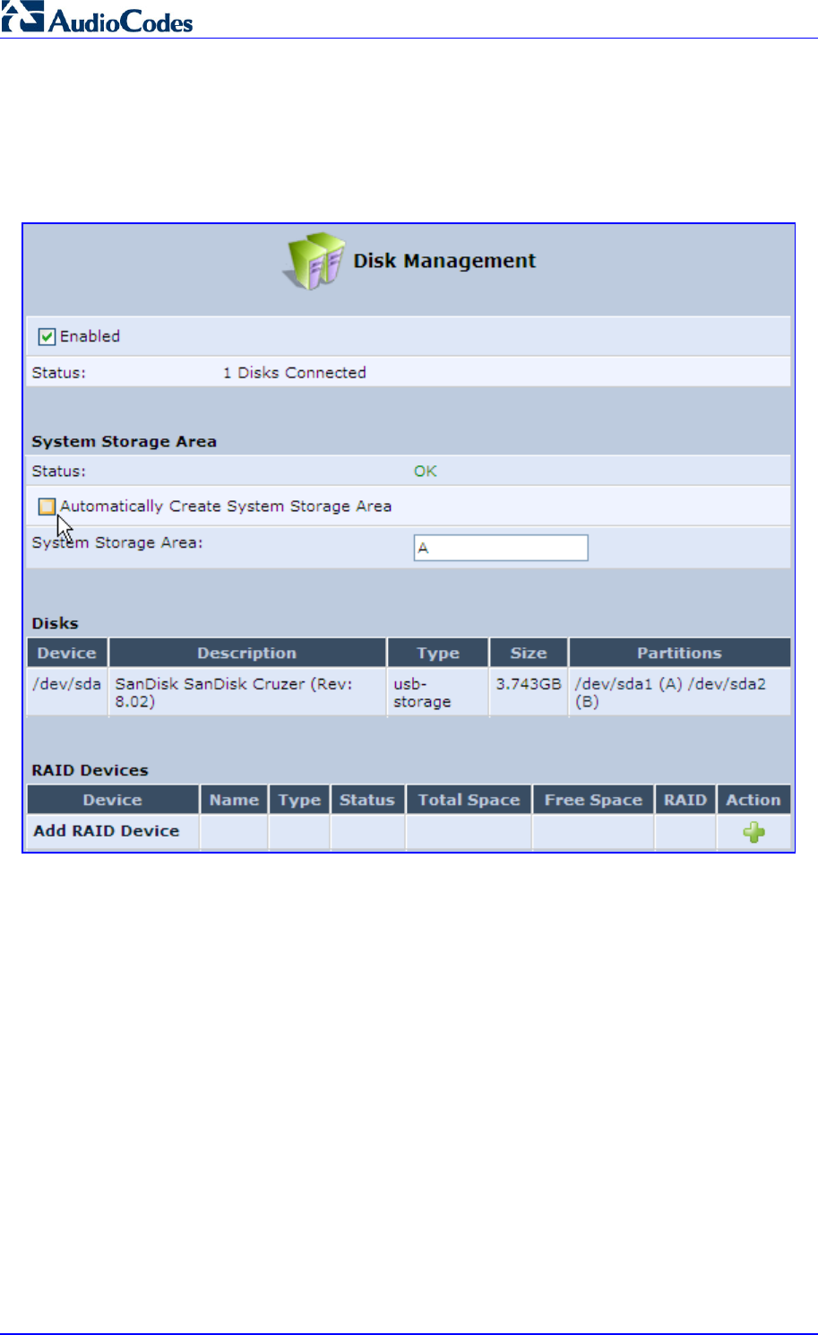
MP252 Multimedia Home Gateway 274 Document #: LTRT-23504
User's Manual
¾ To define a system storage area:
1. Under the System Storage Area group in the 'Disk Management' screen, clear the
‘Automatically Create System Storage Area’ check box; the screen refreshes displaying
the 'System Storage Area' field, in which you must enter the partition's letter.
Figure 17-17: Disk Management Screen – Check Box Cleared
2. Click OK to save the settings.
If you wish to view the system directories, verify that the system storage area is shared.
Then, browse to \\mp252 (use a Windows Explorer window if you are using a browser other
than Internet Explorer).
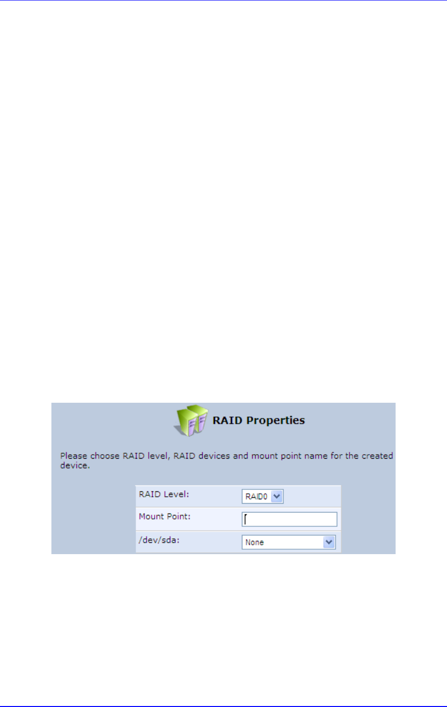
MP252 Multimedia Home Gateway 17. Add-On Servers and Disk Management
Version 3.4.0 275 June 2011
17.2.3 RAID Management
MP252 supports Redundant Array of Independent Disks (RAID) on storage devices
connected to it by USB or by FireWire. A RAID device is a logical device that has physical
devices underlying it. These physical devices are disk partitions. The supported RAID levels
are:
Level 0 – Provides data striping, or spreading out blocks of each file across multiple
disk drives, but no redundancy. This improves performance but does not deliver fault
tolerance. If one drive fails then all data in the array is lost.
Level 1 – Provides disk mirroring. This is a technique in which data is written to two
duplicate disks simultaneously, providing data redundancy. This method improves
performance and delivers fault tolerance.
Level 5 – With a minimum of three disks, this level provides data striping and utilizes
one disk for backup information, which enables it to restore any other disk in the array.
Before creating the RAID device, you must create disk partitions (as described previously) on
the different disk drives. Each RAID device can have multiple underlying devices (partitions).
When using RAID1, it is recommended that these partitions be of the same size to avoid
disk-space loss due to mirroring. A disk partition configured with RAID can no longer be
managed as a regular partition, but only be controlled by the RAID device. From the moment
RAID is configured, it is the RAID device that can be shared, scanned, formatted and
mounted as a regular partition.
17.2.3.1 Creating a RAID Device
The procedure below describes how to create a RAID device.
¾ To create a RAID device:
1. In the RAID Devices table in the ‘Disk Management’ screen, click the Add RAID
Device link; the 'RAID Properties' screen appears:
Figure 17-18: RAID Properties Screen
2. From the ‘RAID Level’ drop-down list, select the RAID level (RAID0, RAID1 or RAID5).
3. In the 'Mount Point' field, enter a name for the mount point of the RAID device.
4. Choose the underlying devices (your pre-configured partitions) in the next drop-down
lists. For RAID1 you may choose only one device and later add another one.
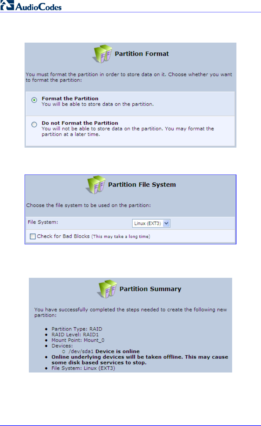
MP252 Multimedia Home Gateway 276 Document #: LTRT-23504
User's Manual
5. Click Next; the 'Partition Format' screen appears.
Figure 17-19: Partition Format Screen
6. Select 'Format the partition' and then click Next.
Figure 17-20: Partition File System Screen
7. Select the format type, and then click Next; the 'Partition Summary' screen displays a
summary of the chosen device properties.
Figure 17-21: Partition Summary Screen
8. Click the Finish button to execute the RAID device creation.
As soon as a RAID device is created, its formatting begins. If the device is RAID1 and has
two underlying devices, its re-synchronization process (partition mirroring) begins
simultaneously. During re-synchronization the RAID device is fully usable and can be
mounted and used.
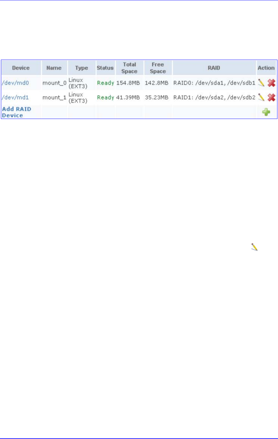
MP252 Multimedia Home Gateway 17. Add-On Servers and Disk Management
Version 3.4.0 277 June 2011
The figure below depicts a successful configuration of two RAID devices as they appear in
the Raid Devices table in the 'File Server' screen. The first is RAID0, consisting of two
underlying partitions (one on each disk), and the second is RAID1, consisting of another set
of underlying partitions. Note that the RAID0 total space is the sum of the two partitions, while
the RAID1 total space is the size of one partition (due to mirroring).
Figure 17-22: Added RAID Devices
17.2.3.2 Using a RAID Device
When RAID is configured over the existing partitions, these partitions are no longer
independent. It is therefore necessary that you update the location of the system storage
area:
1. In the 'Disk Management' screen, verify that the 'Automatically Create System Storage
Area' check box is selected. If you wish to define the system storage area manually,
clear the check box and enter the name of the designated mount point.
2. Click OK to save the settings.
17.2.3.3 Maintaining a RAID Device
A RAID device differs from a regular partition by not being part of a physical disk. It therefore
resides and is maintained on MP252. RAID maintenance is divided into two aspects:
Maintaining the RAID device itself:
• In the RAID Device table in the 'Disk Management' screen, click the Edit icon of
the RAID device; the 'RAID Properties' screen appears in which you can:
♦ Enable or disable the RAID device using the 'Enabled' check box.
♦ Change the mount point assigned to the device.
♦ Add or remove the underlying devices (can be done for RAID1 and RAID5
only).
Maintaining the partition:
• In the 'RAID Properties' screen, click the device name; the 'Partition Properties'
screen appears in which you can check and format the RAID partition.
17.2.3.4 Replacing RAID Underlying Devices
Adding or removing a RAID underlying device can only be performed on RAID1 and RAID5
configurations. RAID1 can operate with just one device (although mirroring is unavailable),
and RAID5 can operate with one device less than its original amount of devices.
The names of the RAID underlying devices appear on the 'RAID Properties' screen. Each
device is followed by a status:
Active: The device is controlled by RAID.
Inactive: The device failed to join the RAID array or does not exist.
Faulty: The device joined the RAID array but was marked as faulty due to an error. It is
inactive and should be replaced.
Replacing a device on RAID1 or RAID5 is done by first removing the faulty device and then
adding a new one. The new device's size must be at least the size of the existing one.

MP252 Multimedia Home Gateway 278 Document #: LTRT-23504
User's Manual
¾ To remove a faulty device from RAID1:
1. In the 'RAID Properties' screen, click the faulty device's Delete icon.
2. Click OK.
¾ To add a new device instead of the one removed:
1. In the RAID Device table in the 'Disk Management' screen, click the Edit icon of the
RAID device; the 'RAID Properties' screen appears with a drop-down list allowing you to
choose the new partition to be added.
2. Choose the partition, and then click OK.
After adding a new device, RAID1 starts a recovery process in which the content of the
existing partition is mirrored to the new device. If the addition or recovery fails, the device
status is set to inactive (this status appears in the 'RAID Properties' screen. In such cases,
the device should be removed and another may be added. You can manipulate your disk
partitions. However, it is recommended to configure your disks before setting up RAID. Once
RAID is configured, you will not be able to delete an underlying partition, or create a new
partition on a disk that one of its partitions is underlying RAID, unless you disable or delete
the RAID device. Changing a disk's partition table when its partitions are under RAID (even if
RAID is disabled) may result in the need to reconstruct the RAID.
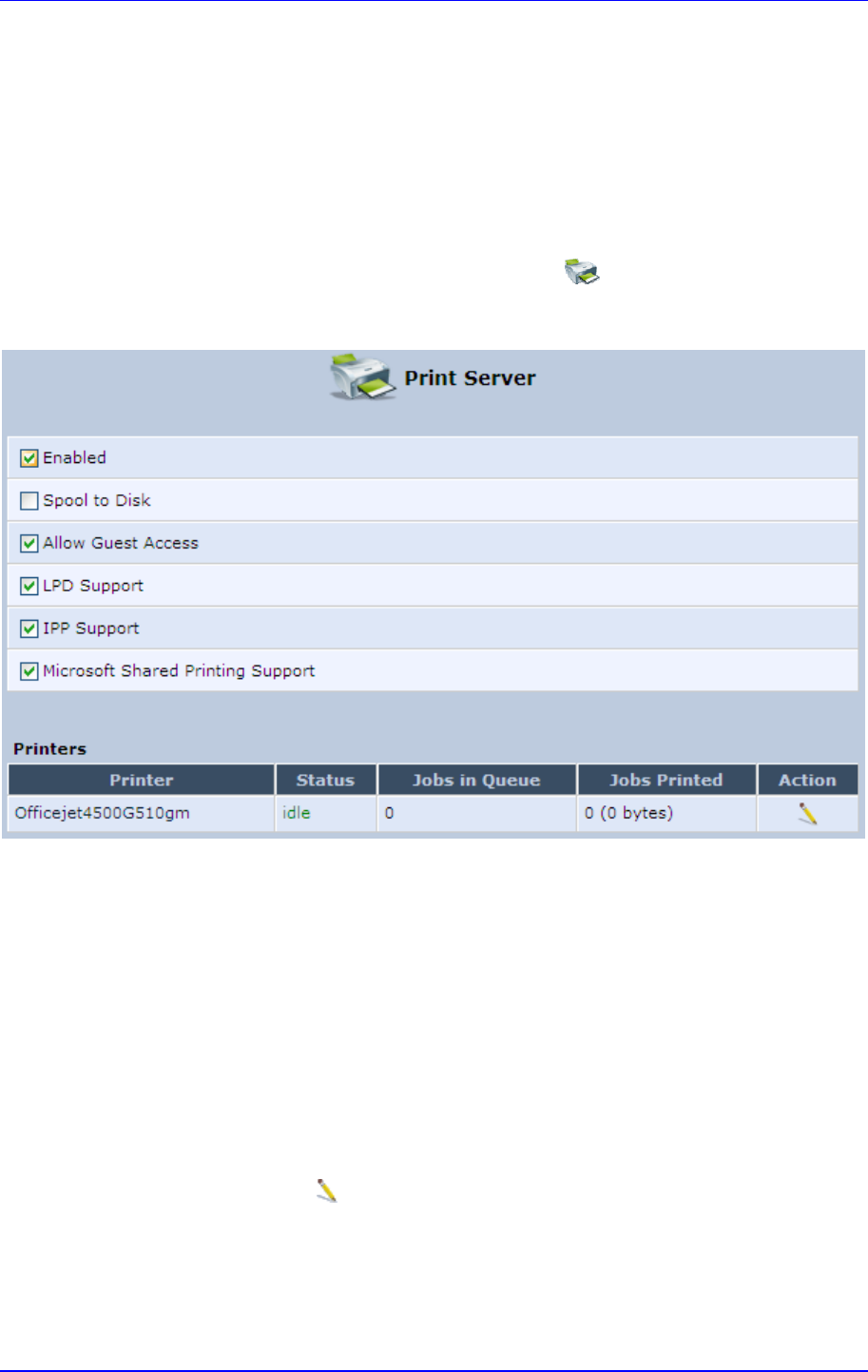
MP252 Multimedia Home Gateway 17. Add-On Servers and Disk Management
Version 3.4.0 279 June 2011
17.3 Print Server
MP252 includes a print server that allows printers attached to MP252 through the USB
connection(s) to be shared by all computers on the LAN. Such a printer appears in the
Network Map. You can access the printer settings directly, by clicking the printer icon in the
Network Map or as described below.
¾ To configure a print server:
1. In the 'Advanced' screen, click the Print Server icon; the ‘Print Server’ screen
appears.
Figure 17-23: Advanced – Print Server Screen
2. Select or clear (as required) the following check boxes:
• Enabled: Enables or disables the print server feature.
• Spool to Disk: Allows print jobs to be written to a disk before printing.
• Allow Guest Access: Allows network users that have not logged in with a
username and password to use the shared printer. If you want to restrict access to
the network printer, you can clear this check box and grant user-specific
permissions by creating a user set to ‘Internet Printer Access’ (see Section 4.4).
• LPD Support: Enables the LPD protocol.
• IPP Support: Enables the IPP protocol.
• Microsoft Shared Printing Support: Enables the Samba protocol.
3. The Printers table lists the MP252 printers, their status as well as their print job
information. To view the printer’s properties and optionally, to define a new name for the
printer, click the Edit icon corresponding to the printer; the 'Printer' screen appears.
Figure 17-24: Advanced – Printer Screen
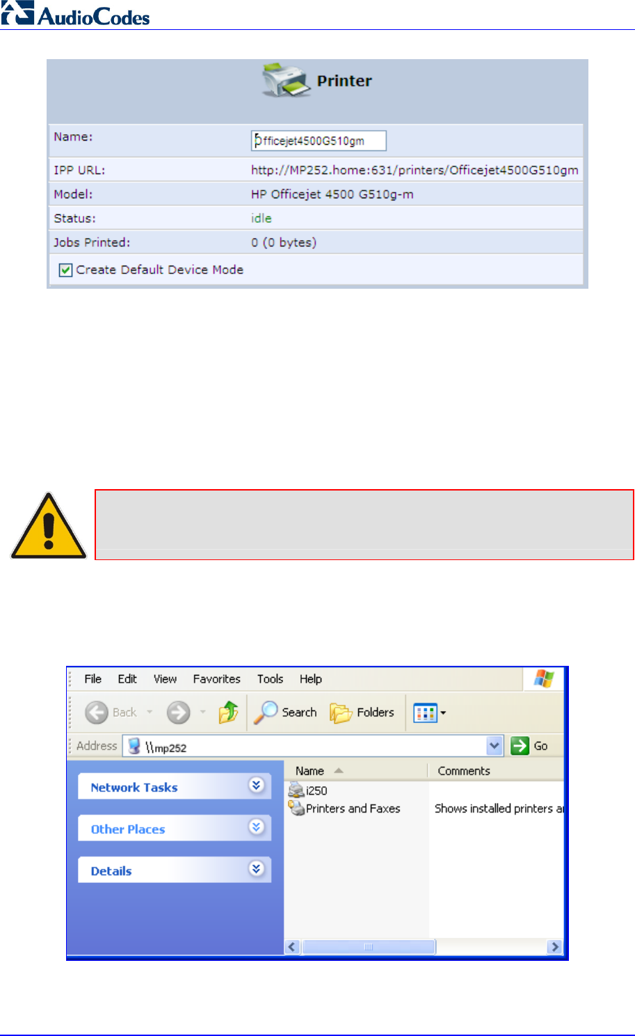
MP252 Multimedia Home Gateway 280 Document #: LTRT-23504
User's Manual
4. To change the displayed name of the printer, in the ‘Name’ field, enter a new name.
5. To set the printer as the default printer, select the ‘Create Default Device Mode’ check
box.
17.3.1 Connecting and Setting up a Printer on Windows
The procedure below describes how to set up a network printer that is connected to the
MP252 USB port and shared by all LAN computers, running on the Windows operating
system.
Note: The above configuration must be applied to each LAN PC individually in order
to use the network printer.
¾ To set up a printer running on Windows:
1. Log in to MP252; the disk and printer shares available on MP252 is displayed:
Figure 17-25: MP252 Shares
2. Click the printer icon that you want to designate as a LAN printer; a warning appears.
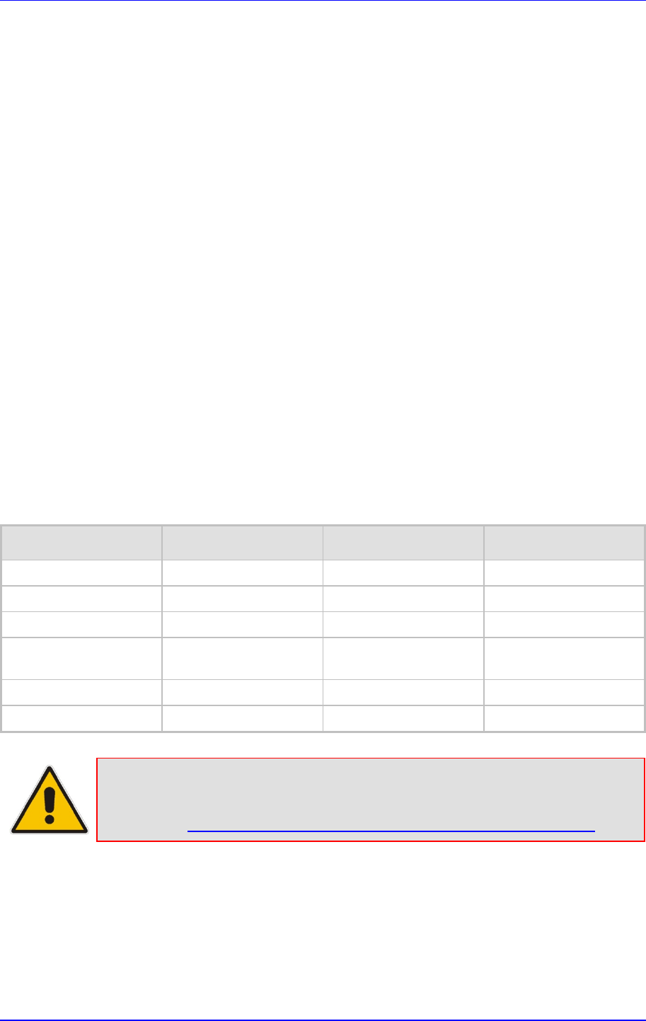
MP252 Multimedia Home Gateway 17. Add-On Servers and Disk Management
Version 3.4.0 281 June 2011
3. Click Yes; you are prompted to select a printer driver from a list. If unavailable, you can
either browse to a location on your computer where you have stored the driver, or click
Have Disk and insert the CD containing the driver (supplied with your printer). After a
short upload and installation of the driver, the printer's print queue window appears,
determining that the printer is ready for use. The new printer is added to your "Printers
and Faxes" list as a network printer (to view this list press, in Windows Control Panel,
select "Printers and Faxes"). As any printer, you can choose to make it your default
printer, or specify its use when printing.
4. Print a test page by right-clicking the printer icon in the disk and printer shares window
and selecting Properties; the 'Print Test Page' button is located at the bottom of the
General tab.
17.3.2 Print Protocols
The Samba protocol with which you have created a network printer in the previous section,
allows you to upload Windows print drivers to MP252, enabling all Windows-based LAN
hosts to connect to the network printer.
MP252 provides two additional protocols for computers to connect to its printers:
Internet Printing Protocol (IPP) - the recommended protocol, offering fast installation
and ease of use.
Line Printer Daemon (LPD) - legacy network printing protocol, which should only be
used for printing from computers that do not support IPP.
The following table compares the specifications of the three protocols:
Table 17-1: IPP, Samba, and LPD Specifications
Specification IPP Samba LPD
Installation Easy Easy Difficult
Driver upload None Supported None
Supported clients Windows, Unix, Mac Windows, Mac Windows, Unix, Mac
Job feedback and
control
Print queue monitor and
management console
Print queue monitor and
management console
Management console
only
Printer control Print queue monitor None None
Access controls Print and administrator Print permission only None
Note: For Mac Users: When connecting a print server to a MAC computer, you must
verify that the printer connected to MP252 is supported by Mac OS as a
network printer. Supported printers are marked with an "X" at the following
URL: http://docs.info.apple.com/article.html?artnum=301175#hpdrivers.
17.3.2.1 Internet Printing Protocol
This section describes how to connect computers to MP252 printers, using the IPP protocol.
17.3.2.1.1 Setting Up an IPP Printer on Windows
The procedure below describes how to set up an IPP printer on Windows.
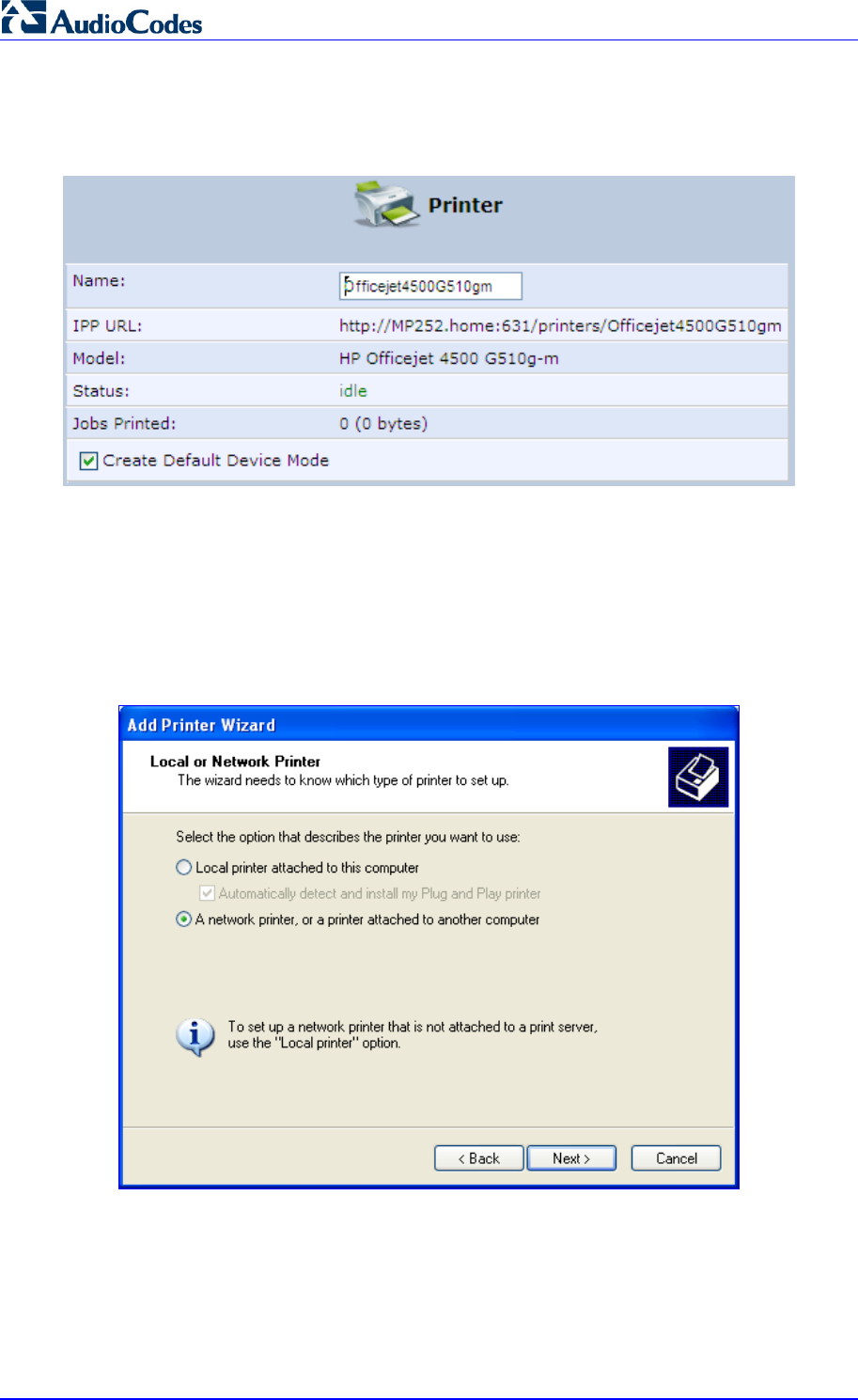
MP252 Multimedia Home Gateway 282 Document #: LTRT-23504
User's Manual
¾ To set up an IPP printer on Windows:
1. In the 'Network Map' screen, click the printer icon to view the 'Printer' screen.
Figure 17-26: Printer Screen – IPP URL
2. Copy the IPP URL to the clipboard.
3. On your Windows computer connected to MP252, from the Start menu, point to
Settings, then Printers and Faxes, and then click Add Printer; the Add Printer Wizard
starts.
4. Click Next to proceed with the wizard sequence.
5. Select 'A network printer…' and then click Next.
Figure 17-27: Local or Network Printer
6. Select 'Connect to a printer on the Internet…', and then paste the printer's IPP URL in
the 'URL' field, and then click Next.
Figure 17-28: Specify a Printer
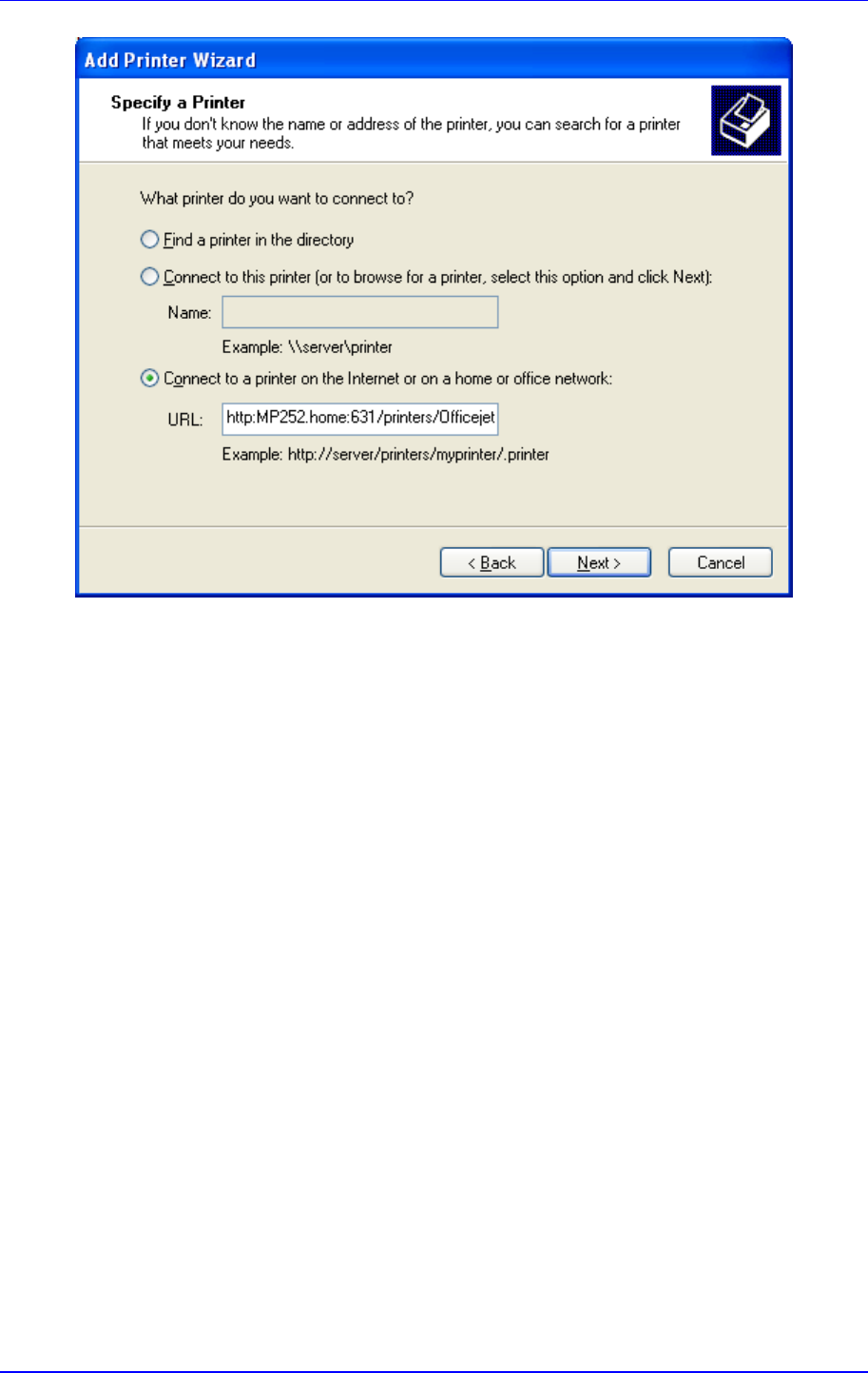
MP252 Multimedia Home Gateway 17. Add-On Servers and Disk Management
Version 3.4.0 283 June 2011
7. You may be asked to select the driver's make and model or its location. If so, provide the
location on MP252 to where you have uploaded the driver (e.g. “\\MP252\A”), and click
Next.
8. Click Finish to exit the wizard.
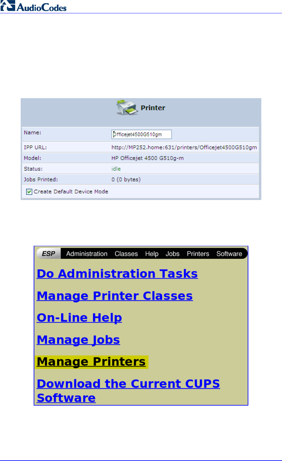
MP252 Multimedia Home Gateway 284 Document #: LTRT-23504
User's Manual
17.3.2.1.2 Setting Up an IPP Printer on Linux
The procedure below describes how to set up an IPP printer on Linux operating systems.
You should use CUPS Daemon (CUPSD) when operating with Linux.
¾ To set up an IPP printer on Linux:
1. In the 'Network Map' screen, click the printer icon to view the 'Printer' screen.
Figure 17-29: Printer Screen – IPP URL
2. Copy the IPP URL to the clipboard.
3. On your Linux computer connected to MP252, browse to http://localhost:631, and then
choose Manage Printers.
Figure 17-30: Linux CUPS Management
4. Click Add Printer.
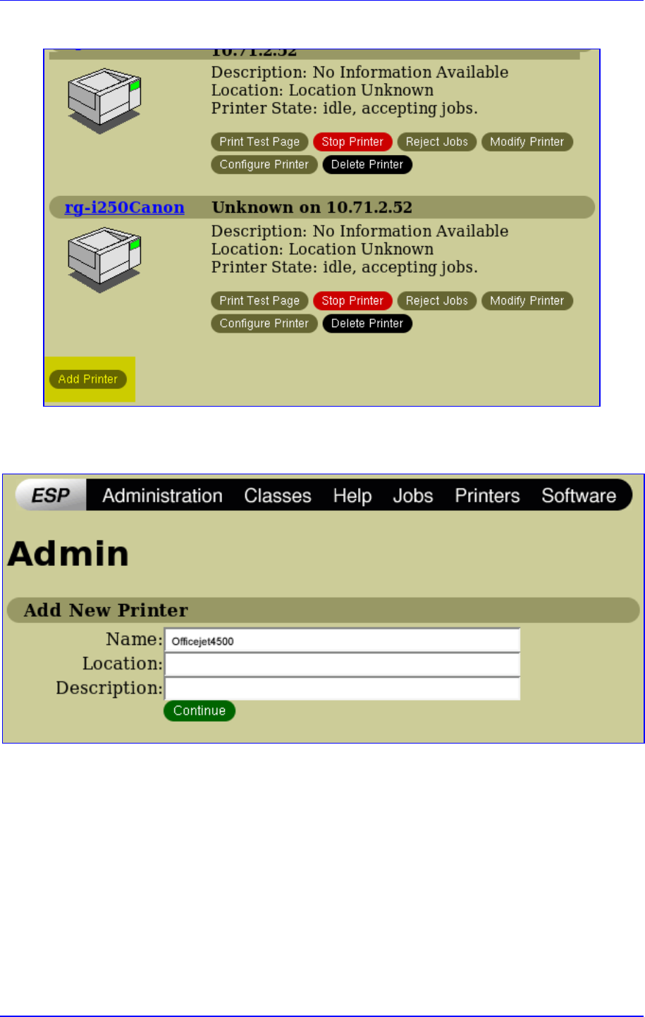
MP252 Multimedia Home Gateway 17. Add-On Servers and Disk Management
Version 3.4.0 285 June 2011
Figure 17-31: Add Printer
5. In the 'Name' field, type the printer's name and then click Continue.
Figure 17-32: Printer Name
6. From the 'Device' drop-down list, select 'Internet Printing Protocol (http)' and then click
Continue.
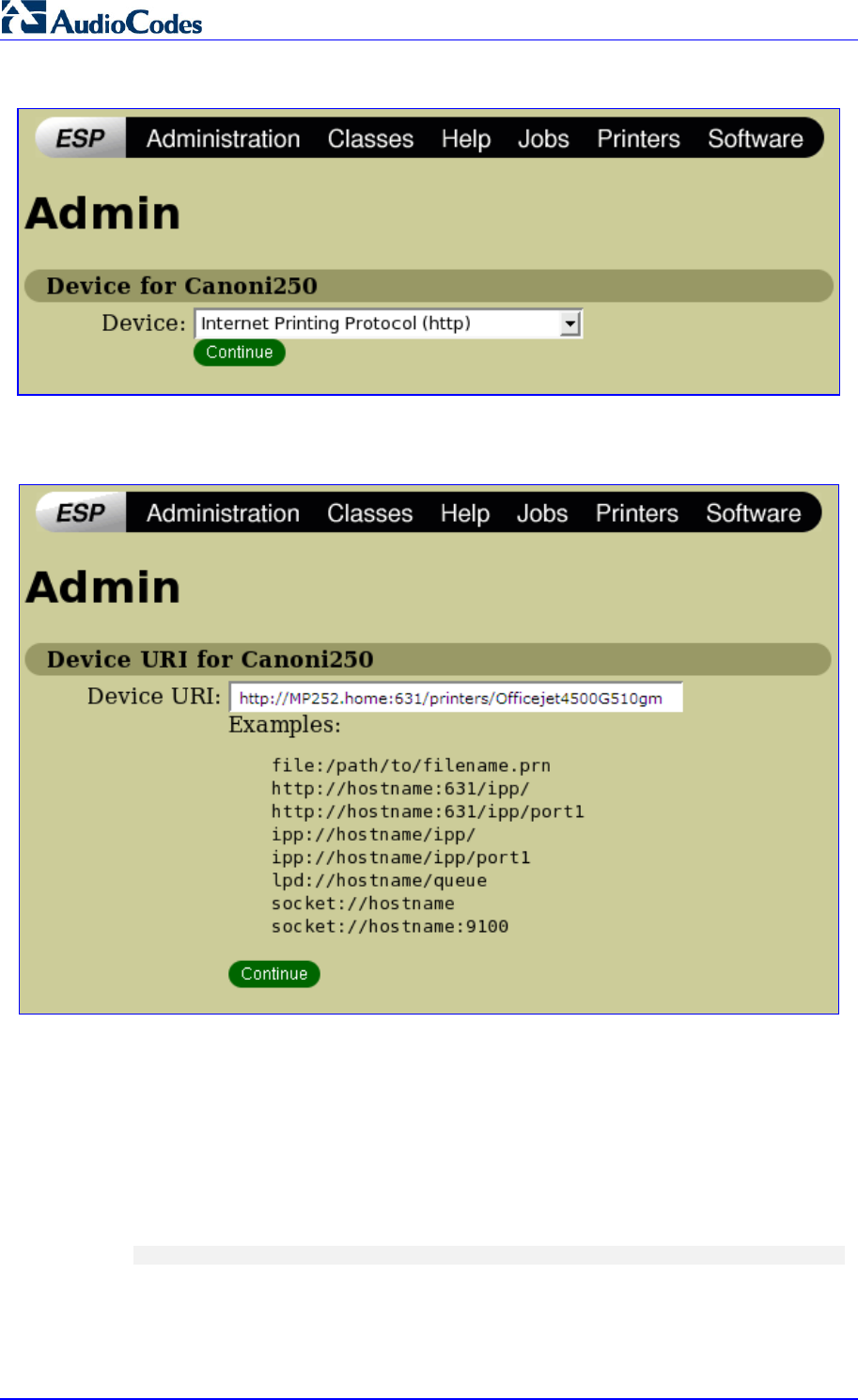
MP252 Multimedia Home Gateway 286 Document #: LTRT-23504
User's Manual
Figure 17-33: Printing Protocol
7. Paste the printer's IPP URL in the 'Device URI' field, and then click Continue.
Figure 17-34: IPP URL
8. The next window displays a manufacturer drop-down list. Select your printer's
manufacturer and click Continue.
9. The next window displays a printer model drop-down list. Select your printer's model
and click Continue.
10. The last window displays the following confirmation message: 'Printer has been added
successfully'.
11. To test your printer's connection from a Linux PC, open a shell and enter the following
command:
$ echo hello | lpr -P<Printer Name>
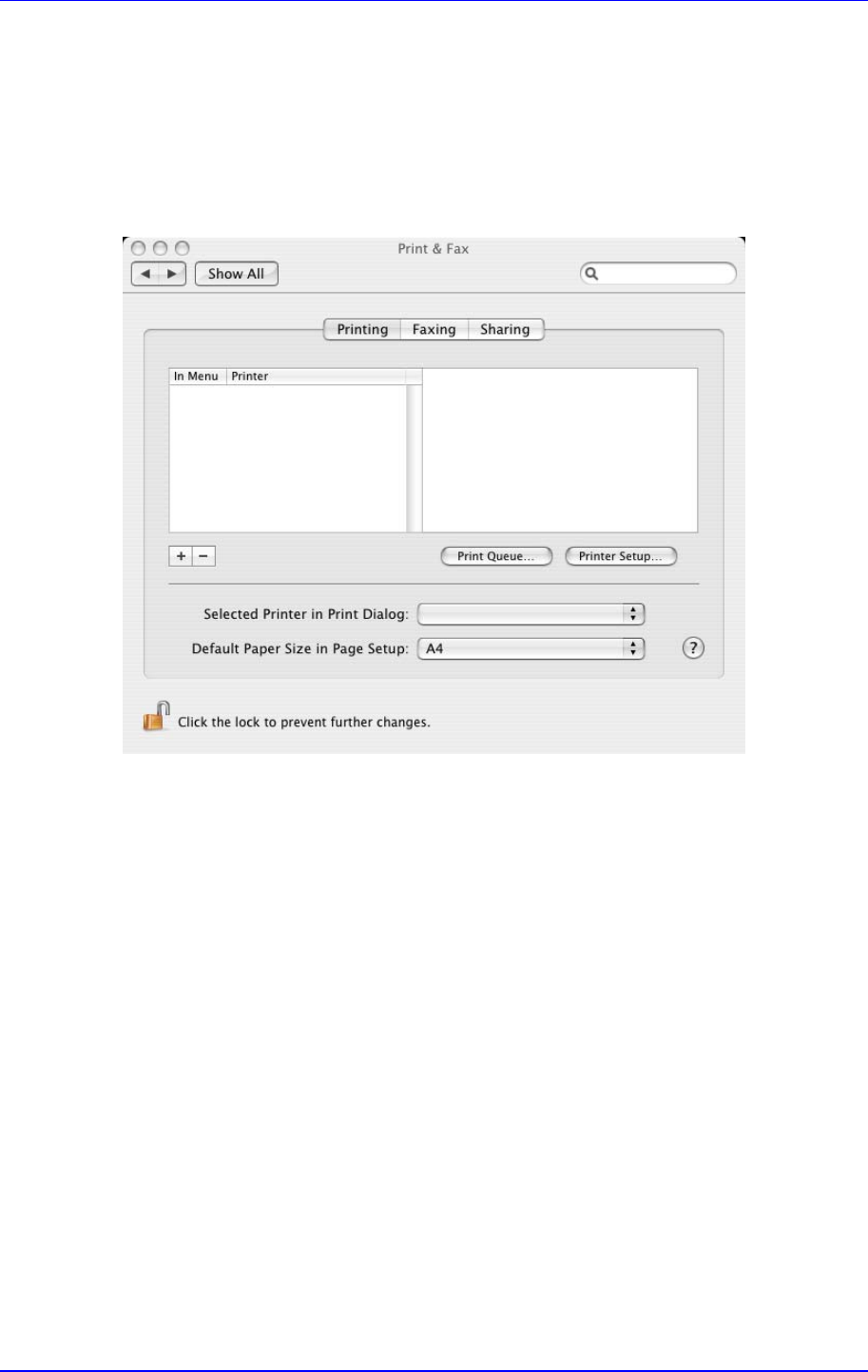
MP252 Multimedia Home Gateway 17. Add-On Servers and Disk Management
Version 3.4.0 287 June 2011
17.3.2.1.3 Setting Up an IPP Printer on Mac
The procedure below describes how to set up an IPP printer on Mac operating systems.
¾ To set up an IPP printer on Mac:
1. On your Mac computer connected to MP252, open the 'Print & Fax' utility from 'System
Preferences'; the 'Print & Fax' screen appears.
Figure 17-35: Print & Fax
2. Click the + (add) button; the 'Printer Browser' screen appears.
3. Select the IP Printer tab.
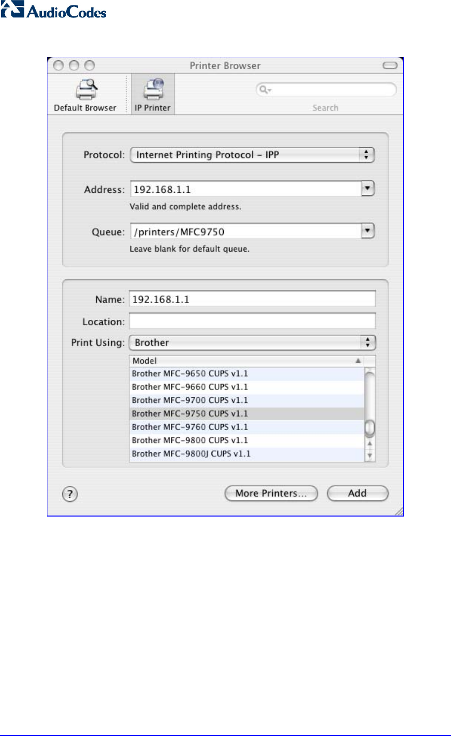
MP252 Multimedia Home Gateway 288 Document #: LTRT-23504
User's Manual
Figure 17-36: Printer Browser – IP Printer
4. In this screen, configure the following:
a. From the 'Protocol' drop-down list, select IPP.
b. In the 'Address' field, enter MP252’s IP address (192.168.1.1).
c. In the 'Queue' field, enter the section of the path containing the folder and printer
names, as it appears in the 'Printer' screen. For example, “/printers/MFC9750”.
d. The 'Name' and 'Location' fields are optional; the default name is the gateway's IP
address.
e. From the 'Print Using' drop-down list, select your printer's make and model.
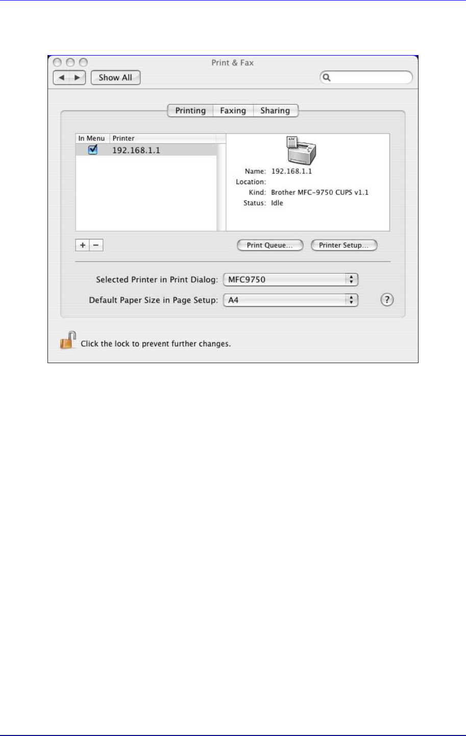
MP252 Multimedia Home Gateway 17. Add-On Servers and Disk Management
Version 3.4.0 289 June 2011
5. Click the Add button; the new printer appears in the 'Print & Fax' screen.
Figure 17-37: Print & Fax – New IPP Printer
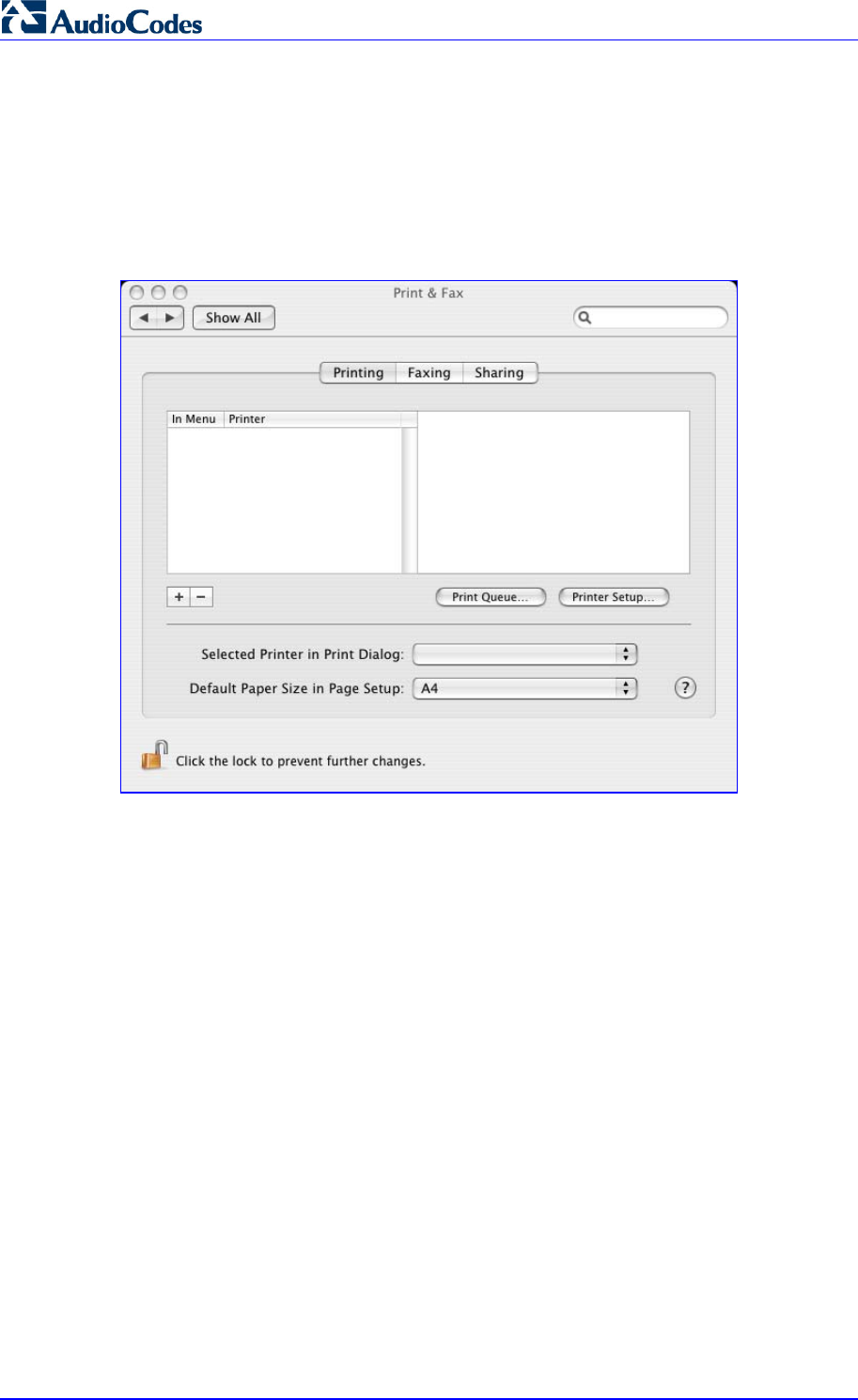
MP252 Multimedia Home Gateway 290 Document #: LTRT-23504
User's Manual
17.3.2.2 Microsoft Shared Printing (Samba)
The procedure below describes how to set up Microsoft Shared Printing (Samba).
¾ To set up Microsoft shared printing (Samba):
1. On your Mac computer connected to MP252, open the 'Print & Fax' utility from 'System
Preferences'; the 'Print & Fax' screen appears.
Figure 17-38: Print & Fax
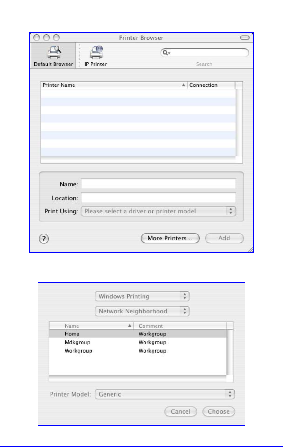
MP252 Multimedia Home Gateway 17. Add-On Servers and Disk Management
Version 3.4.0 291 June 2011
2. Click the + (add) button; the 'Printer Browser' screen appears.
Figure 17-39: Printer Browser – Default Browser
3. Click the More Printers button; The following screen appears.
Figure 17-40: Printer Browser – More Printers
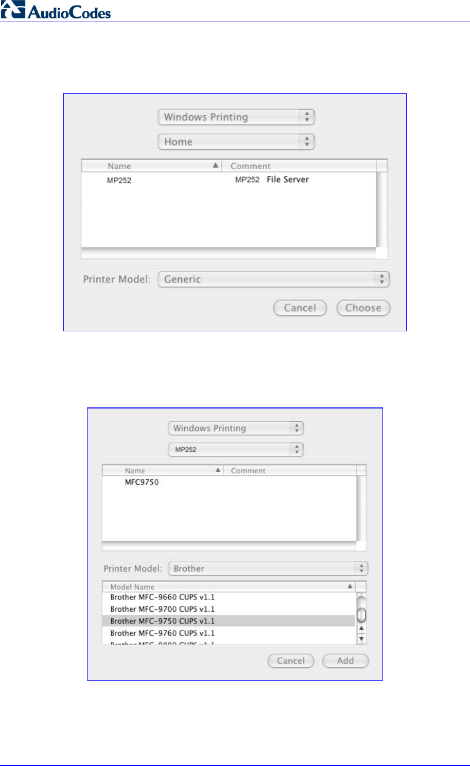
MP252 Multimedia Home Gateway 292 Document #: LTRT-23504
User's Manual
4. From the second drop-down list, select 'Network Neighborhood'.
5. Select the 'Home' workgroup and then click Choose.
Figure 17-41: Printer Browser – MP252
6. Select MP252, and then click Choose.
7. Select the printer, and from the 'Printer Model' drop-down list, select your printer's make
and model.
Figure 17-42: Printer Browser – Printer Model
8. Click Add; the new printer appears in the 'Print & Fax' screen.
Figure 17-43: Print & Fax – New Samba Printer
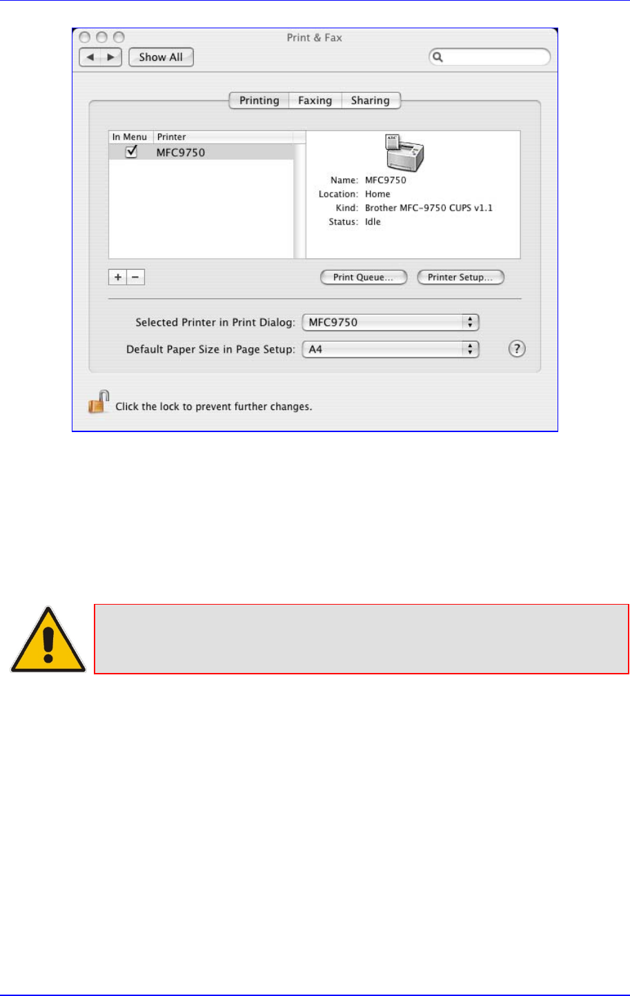
MP252 Multimedia Home Gateway 17. Add-On Servers and Disk Management
Version 3.4.0 293 June 2011
17.3.2.3 Line Printer Daemon (LPD)
This section describes how to connect computers to MP252 printers, using the LPD protocol.
17.3.2.3.1 Setting Up an LPD Printer on Windows
Before configuring the LPD protocol on a LAN PC, ensure that a print driver for the specific
printer is installed.
Note: The following configuration must be applied to each LAN PC individually in
order to use the network printer.
¾ To set up an LPD printer on Windows:
1. On your Windows computer connected to MP252, from the Start menu, point to
Settings, then Printers and Faxes, and then click Add Printer; the Add Printer Wizard
starts.
2. Click Next to proceed with the wizard sequence.
3. Select 'Local printer attached to this computer' and then click Next.
4. Clear the 'Automatically detect and install my Plug and Play printer', and then click Next.
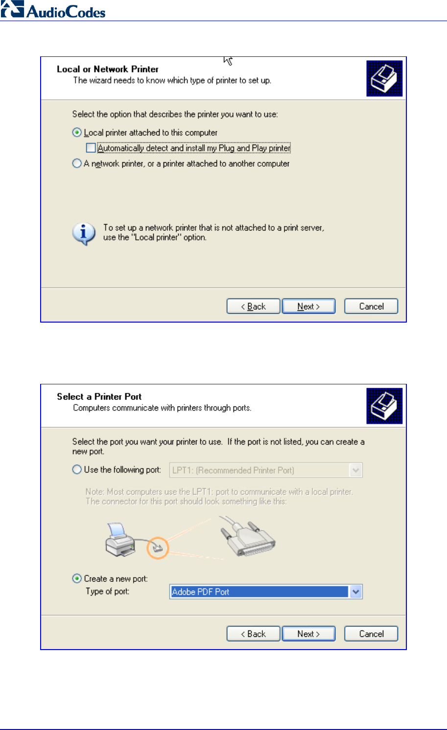
MP252 Multimedia Home Gateway 294 Document #: LTRT-23504
User's Manual
Figure 17-44: Local Printer
5. Select the 'Create a new port' option.
6. From the 'Type of port' drop-down list, select 'Standard TCP/IP Port'.
Figure 17-45: Select a Printer Port
7. Click Next to activate the 'Add Standard TCP/IP Printer Port Wizard'.
8. Click Next to proceed with the new wizard.
9. In the 'Printer Name or IP Address' field, specify 192.168.1.1, and then click Next.
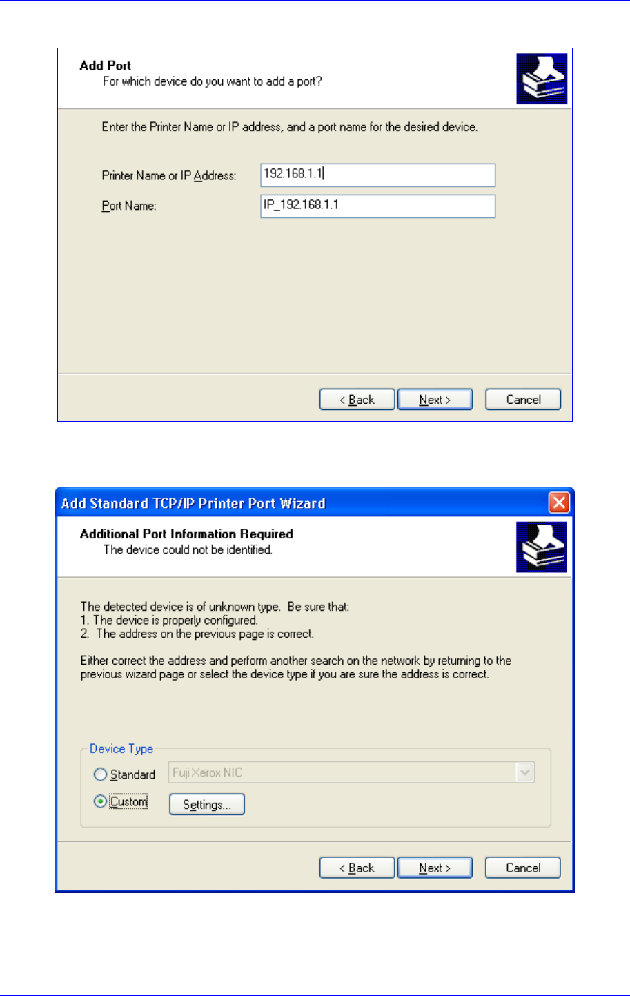
MP252 Multimedia Home Gateway 17. Add-On Servers and Disk Management
Version 3.4.0 295 June 2011
Figure 17-46: Add Port
10. Select the 'Custom' option, and then click Settings.
Figure 17-47: Additional Port Information
11. In the 'Configure Standard TCP/IP Port Monitor' window, configure the following
parameters:
a. Select the 'LPR' option.
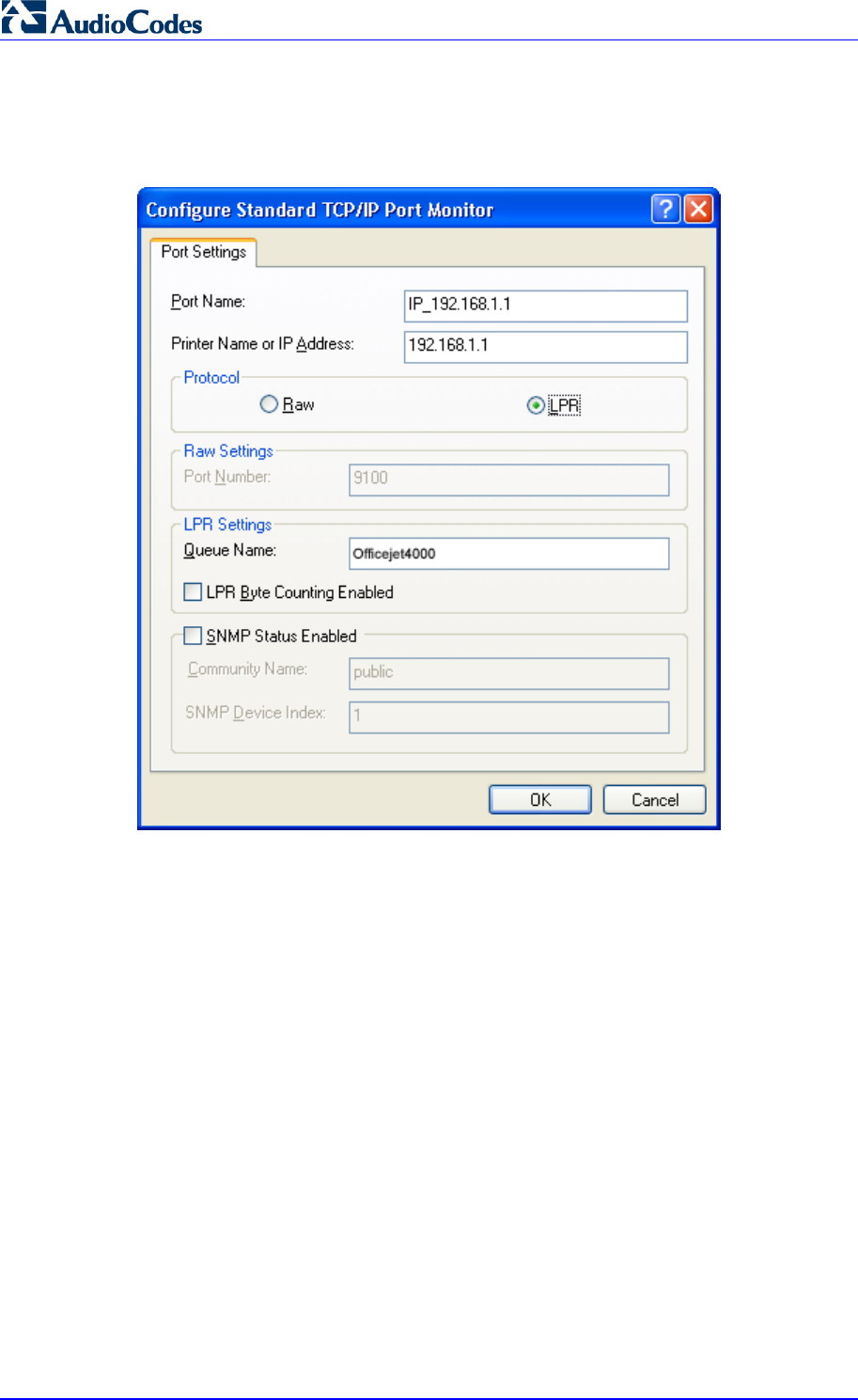
MP252 Multimedia Home Gateway 296 Document #: LTRT-23504
User's Manual
b. In MP252’s Web interface, open the 'Print Server' screen.
c. Copy the printer's name (for example, "Officejet4000") and paste it in the 'Queue
Name' field of the port monitor configuration window.
Figure 17-48: Printer Port Monitor Configuration
12. Click OK, and then click Finish; the 'Add Printer Software' wizard reappears.
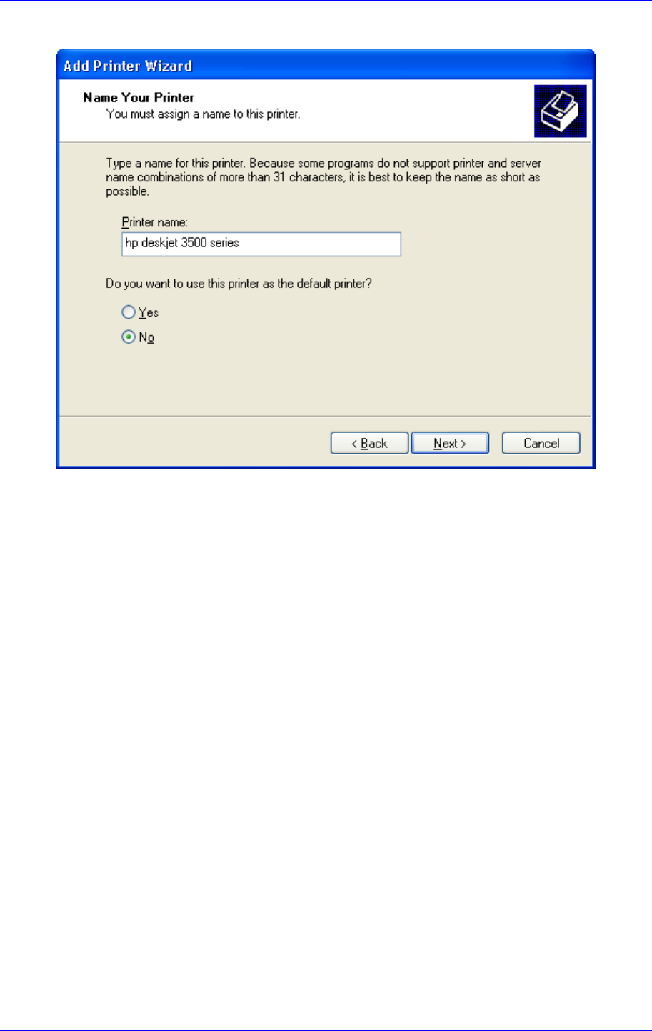
MP252 Multimedia Home Gateway 17. Add-On Servers and Disk Management
Version 3.4.0 297 June 2011
Figure 17-49: Add Printer Wizard
13. Select your printer manufacturer and model from the lists. If it does not appear in the
lists, click 'Have disk' to specify the driver location.
14. Specify the name you want to give the printer, and whether you want it to be the default
printer. Click Next.
15. Click Next to proceed to the final wizard screen.
16. Select Yes to print a test page.
17. Click Finish to complete the setup procedure.
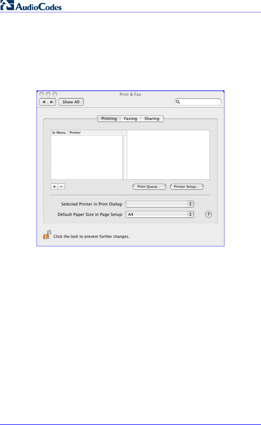
MP252 Multimedia Home Gateway 298 Document #: LTRT-23504
User's Manual
17.3.2.3.2 Setting Up an LPD Printer on Mac
The procedure below describes how to set up an LPD printer on Mac operating systems.
¾ To set up an LPD printer on Mac:
1. On your Mac computer connected to MP252, open the 'Print & Fax' utility from 'System
Preferences'; the 'Print & Fax' screen appears.
Figure 17-50: Print & Fax
2. Click the + (add) button; the 'Printer Browser' screen appears.
3. Select the IP Printer tab and the configure the following:
a. From the 'Protocol' drop-down list, select LPD.
b. In the 'Address' field, enter MP252’s IP address (192.168.1.1).
c. In the 'Queue' field, enter the printer's name as it appears in the 'Printer' screen of
the Web interface. For example, MFC9750.
d. The 'Name' and 'Location' fields are optional; the default name is the gateway's IP
address.
e. From the 'Print Using' drop-down list, select your printer's make and model.
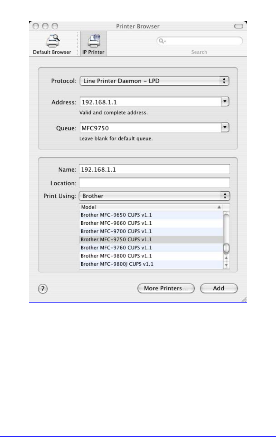
MP252 Multimedia Home Gateway 17. Add-On Servers and Disk Management
Version 3.4.0 299 June 2011
Figure 17-51: Printer Browser – LPD Printer
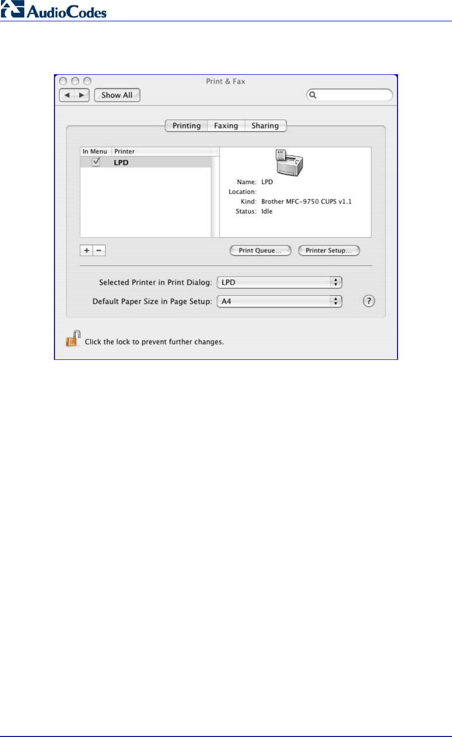
MP252 Multimedia Home Gateway 300 Document #: LTRT-23504
User's Manual
4. Click Add; the new printer appears in the 'Print & Fax' screen.
Figure 17-52: Print & Fax – New LPD Printer
17.3.3 Storing and Using Printer Drivers
As explained earlier in this chapter, to use a shared printer connected to MP252, a driver for
the printer must be installed on the LAN computer from which the print job is to be sent. You
can use the MP252 file server to store printer drivers.
The drivers should be uploaded from a Windows computer and stored in the system storage
area that you have created on one of the disk partitions. The printer can then be installed on
other LAN computers using the driver stored on MP252.
¾ To upload the driver files to MP252:
1. From Window's Start menu, click Run, and then type "cmd" to open a command shell.
2. At the prompt, type net use to view the list of shares and their status.
3. Type net use /del \\mp252\share-B to delete the specific network mapping entry.
Alternatively, you can use net use /del * to delete all network mapping entries.
4. Type net use * \\openrg\print$ [Admin's password] [/user:admin]. This ensures that
you are logged into the print server using the Admin user and have the permissions to
upload files.
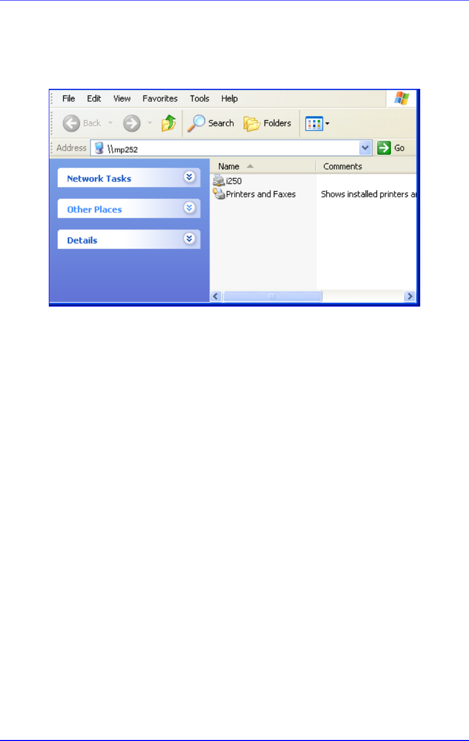
MP252 Multimedia Home Gateway 17. Add-On Servers and Disk Management
Version 3.4.0 301 June 2011
5. Browse to \\mp252 (use a Windows Explorer window if you are using a browser other
than Internet Explorer). Should a Windows login dialog box appear, enter your Web
username and password. The following window appears, displaying the disk and printer
shares available on MP252.
Figure 17-53: MP252 Shares
6. Click Printers and Faxes.
7. Right-click the printer icon, and then select Properties.
8. If your operating system does not already have the driver, you will be asked if you want
to install it now. Click No.
9. Select the Advanced tab, and then click New driver; the 'Add Printer Driver Wizard on
MP252 starts. You are prompted to select a printer driver from a list. If unavailable, you
can either browse to a location on your computer where you have stored the driver, or
click Have Disk and insert the CD containing the driver (supplied with your printer).
10. Click OK; the driver is uploaded to MP252’s system storage directory (e.g. “\\mp252\A”).
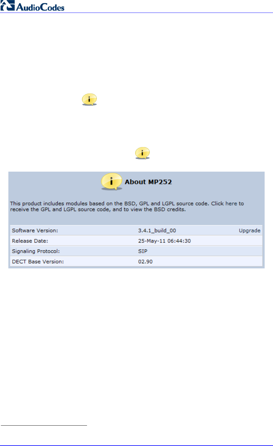
MP252 Multimedia Home Gateway 302 Document #: LTRT-23504
User's Manual
18 Maintenance
18.1 About MP252
The About MP252 icon displays information about MP252. This includes the software
version, release date, signaling protocol, and DECT base unit version5. You can also
upgrade the software running on MP252, by clicking the Upgrade link (for more information,
see Section 18.5 on page 315).
¾ To view information about MP252:
In the 'Advanced' screen, click the icon; the 'About MP252' screen appears.
Figure 18-1: About MP252 Screen
5
The DECT feature is applicable only to the MP252WDNB model.
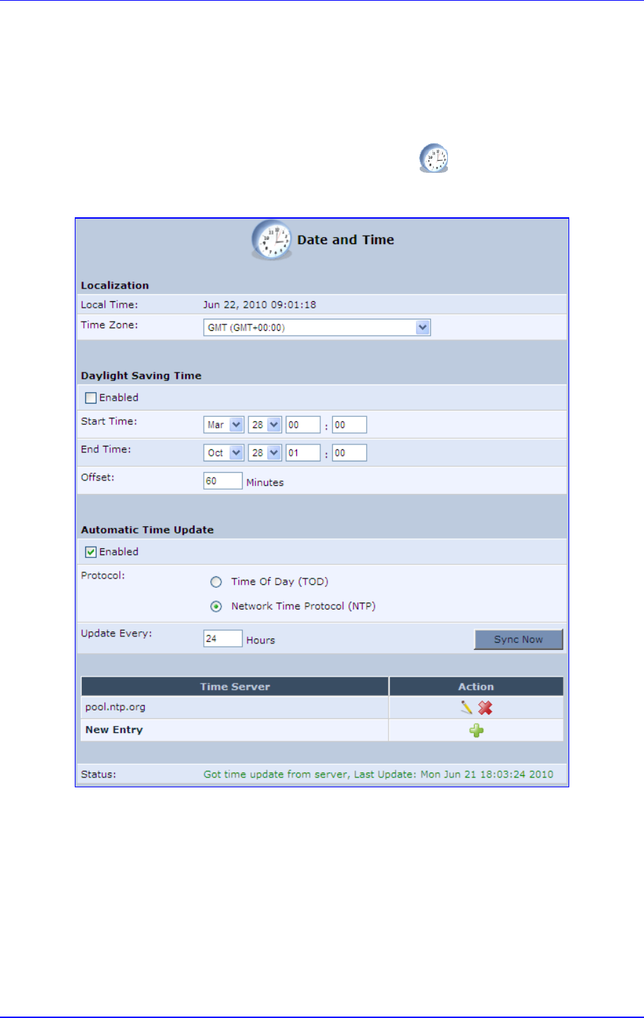
MP252 Multimedia Home Gateway 18. Maintenance
Version 3.4.0 303 June 2011
18.2 Date & Time
The procedure below describes how to set the date and time.
¾ To configure date, time and daylight savings time settings:
1. In the 'Advanced' screen, click the Time Settings icon; the 'Date & Time' screen
appears.
Figure 18-2: Date and Time Screen
2. From the 'Time Zone' drop-down list, select the local time zone. MP252 can
automatically detect daylight saving setting for selected time zones.
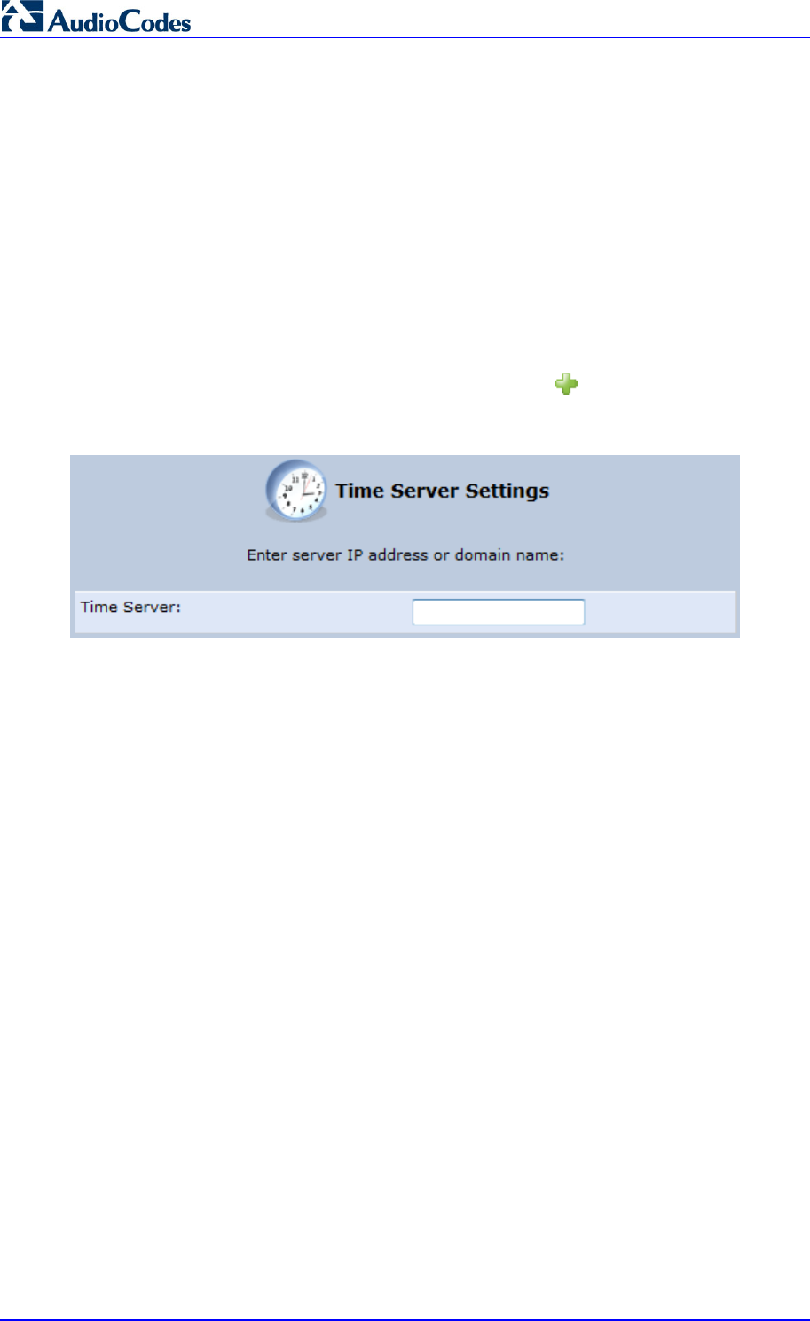
MP252 Multimedia Home Gateway 304 Document #: LTRT-23504
User's Manual
3. Under the Daylight Saving Time group, configure the daylight saving settings for your
time zone (if they are not automatically detected):
• Enabled: Select this check box to enable daylight saving time.
• Start: Date and time when daylight saving starts.
• End: Date and time when daylight saving ends.
• Offset: Daylight saving time offset.
4. For the MP252 to perform an automatic time update, under the Automatic Time
Update group, do the following:
a. Select the 'Enabled' check box.
b. Select the protocol to be used for time update, by selecting either the 'Time of Day'
or 'Network Time Protocol' option.
c. In the 'Update Every' field, specify how often to perform the update.
d. You can define NTP servers, by clicking the New icon; the ‘Time Server
Settings’ screen appears.
Figure 18-3: Time Server Settings Screen
e. In the ‘Time Server’ field, enter the IP address of the Time server (NTP), and then
click OK.
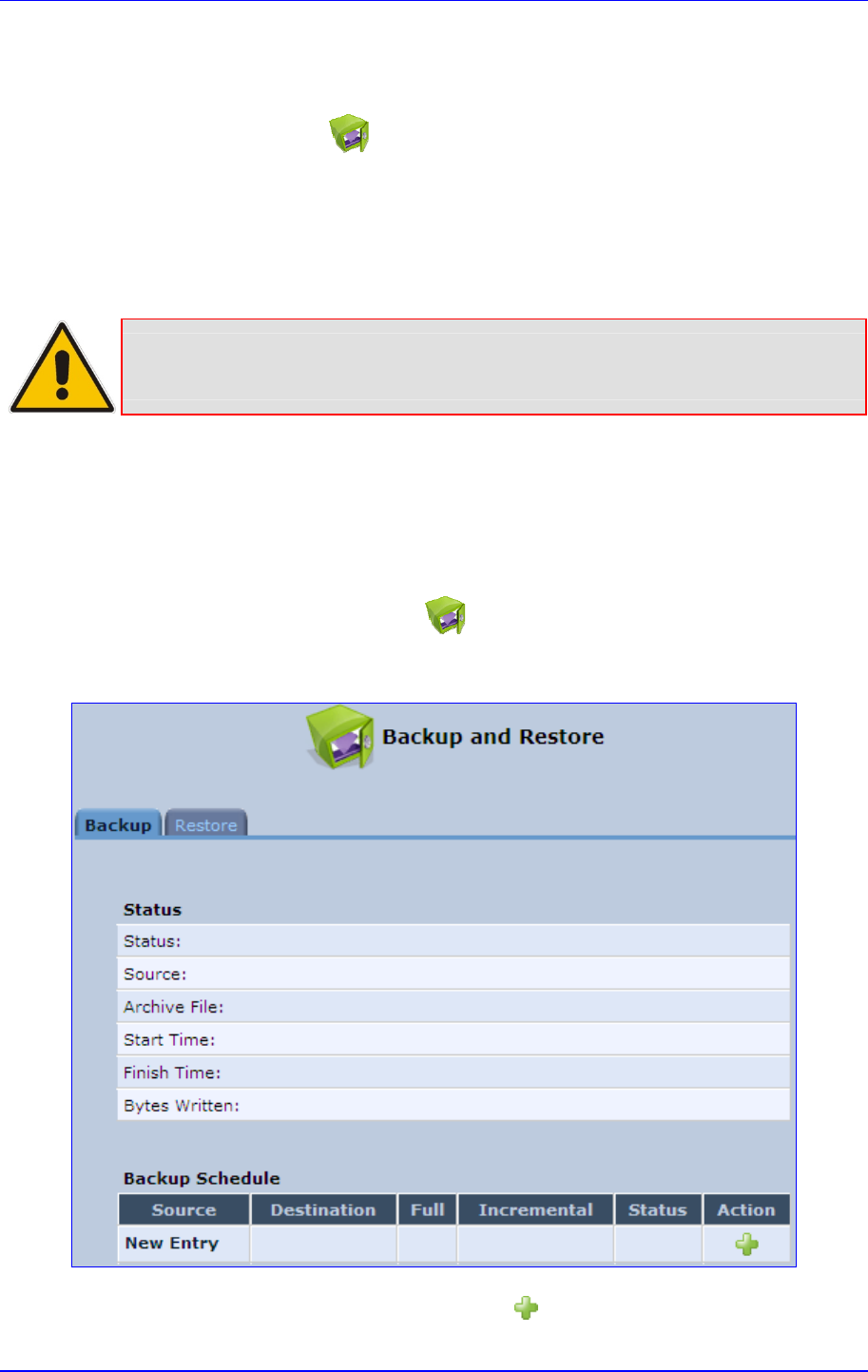
MP252 Multimedia Home Gateway 18. Maintenance
Version 3.4.0 305 June 2011
18.3 Backup and Restore
The Backup and Restore icon allows you to configure the MP252 backup facility for
backing up data, stored in the system storage area, to external USB disks. You may specify
backups to run automatically at scheduled times.
Two prerequisites must be met before enabling the backup mechanism:
The file server feature must be activated and configured
The file server must consist of at least two disks
Note: The backup is done at the directory level. In other words, it is not possible to
backup a single stand-alone file.
18.3.1 Backing Up Data
The procedure below describes how to backup data.
¾ To backup data:
1. In the 'Advanced' screen, click the icon; the ‘Backup and Restore’ screen appears.
2. Select the Backup tab.
Figure 18-4: Backup and Restore Screen
3. In the ‘Backup Schedule’ table, click the New icon; the 'Edit Backup' screen appears.
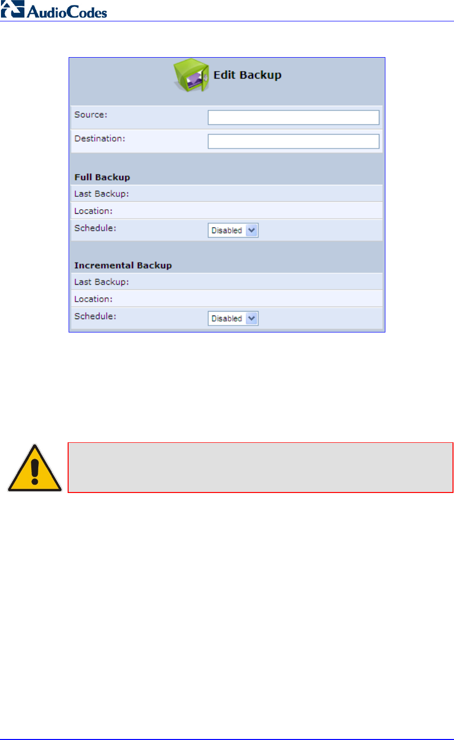
MP252 Multimedia Home Gateway 306 Document #: LTRT-23504
User's Manual
Figure 18-5: Edit Backup Screen
4. In the ‘Source’ field, type the source to backup, for example, “A/homes”.
5. In the ‘Destination’ field, type the destination of the backup files, for example,
“B/backups”. It is recommended that the destination is an external storage device.
6. Choose between full backup, incremental backup, or both, by scheduling a time for the
backup operation. You can choose between daily, weekly or monthly backups in the
'Schedule' drop-down lists.
Note: Do not schedule a monthly backup on the 31st of the month, as backups do not
run on months with 30 days.
7. Click OK to save the schedule settings.
8. Click Backup Now to run the backup operation immediately. When backing up, the
screen displays the status and progress of the operation.
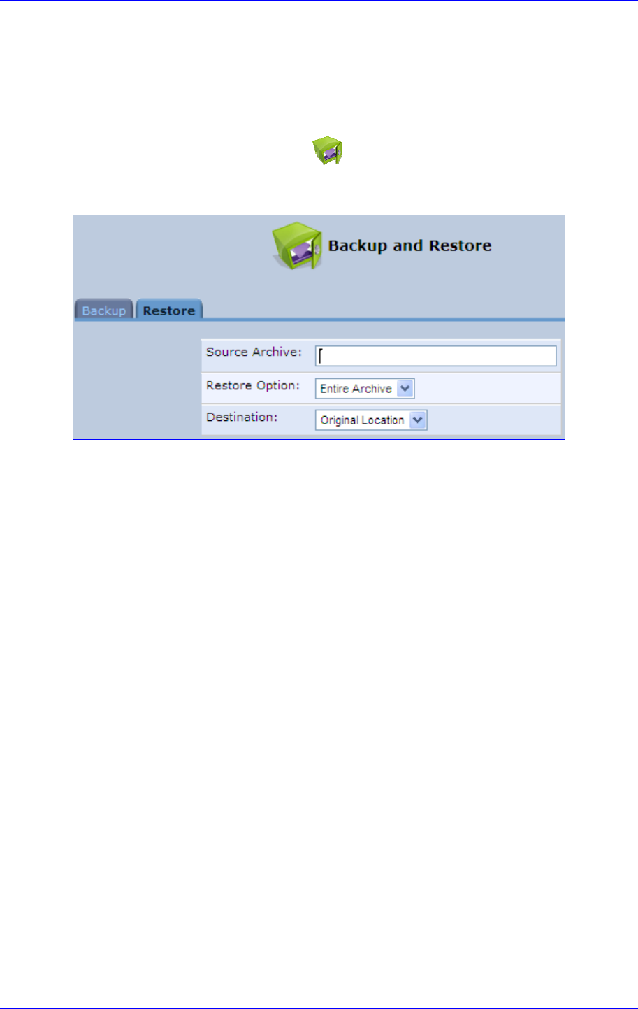
MP252 Multimedia Home Gateway 18. Maintenance
Version 3.4.0 307 June 2011
18.3.2 Restoring Your Data
The procedure below describes how to restore data.
¾ To restore data:
1. In the 'Advanced' screen, click the icon; the ‘Backup and Restore’ screen appears.
2. Select the Restore tab; the 'Restore' screen appears.
Figure 18-6: Restore Screen
3. In the 'Source Archive' field, type the source to restore, for example, “A/homes”.
4. From the 'Restore Option' drop-down list, select whether to restore the entire archive or
only a subdirectory. If you choose subdirectory, a second field appears in which you
must enter the name of the subdirectory relative to the source archive. For example, to
restore “A/homes/john”, type “john” as the subdirectory.
5. From the ‘Destination' drop-down list, select a destination for which to restore the
archive. You can choose the original location or any other directory. If you choose
another directory, a second field appears in which you must enter the name of the
directory. Note that the path of the restored directory is created under the path of the
destination directory. For example, if you specify the directory “A/restore_dir”, the result
is “A/restore_dir/A/homes/john”.
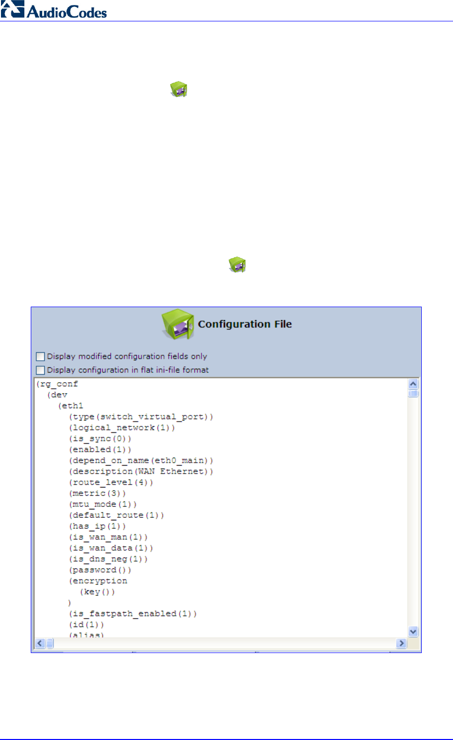
MP252 Multimedia Home Gateway 308 Document #: LTRT-23504
User's Manual
18.4 Configuration File
The Configuration File icon allows you to view, save, and load the MP252
configuration file. Therefore, you can backup and restore your current configuration.
MP252 also supports configuration file encryption, allowing you to load encrypted
configuration files (using the file name extensions *.cfx or *.inx). For more information on
encrypting a configuration file, see Section 18.4.3 on page 313.
MP252 allows you to use un-encrypted passwords in the configuration file (*.cfg or *.ini) that
you want to load, and then encrypt the passwords before burning to flash. This is achieved by
using the format {“<value>”} in the configuration file for password fields which are normally
encrypted. Below are two examples of this feature:
ini file: rg_conf/voip/line/1/auth_password={"foobaa"}
cfg file: (auth_password({"foobaa"}))
¾ To save and restore the configuration file:
1. In the 'Advanced' screen, click the icon; the 'Configuration File' screen appears,
showing the entire contents of the configuration file.
Figure 18-7: Configuration File Screen
2. You can customize the displayed configuration file, by selecting the following check
boxes:
• Display modified configuration fields only: Displays only the configuration
parameters that have values other than default values.
MP252 Multimedia Home Gateway 18. Maintenance
Version 3.4.0 309 June 2011
• Display configuration in flat ini-file format: Displays the configuration file in flat
INI-file format.
3. To back up your current configuration to a file on your PC, click Download
Configuration File. The saved configuration file can be used as a backup for the
specific MP252's configuration for creating a configuration file for remote configuration
update, and for debugging and diagnostics. When creating a configuration backup,
disable the two display check boxes (i.e. save a full configuration file in the hierarchic
conf format). This file can be loaded back to the same MP252, using the procedure
described in Section 18.4.1 on page 310.
Note: The file is generated according to the selected display option (in Step 2).
4. To restore your configuration from a file saved on your PC, click Upload Configuration
File.
Note: Do not load this file to a different MP252 as it includes the MAC address, which
is unique to MP252 from where it was saved.
When creating a file for remote configuration update, it is recommended to only select the
'Display modified configuration fields only'. This ensures that the file includes only
parameters that were modified from their default value. You can choose the conf format or
the flat ini-file format. In both cases, it is recommended to review the file and ensure that only
the parameters that the user has intended to modify appear. This file can be placed on an
FTP or HTTP server for mass configuration update, as described in Remote Configuration
Download.
Note: When rebooting, MP252 restores the settings from its configuration file.
However, if reboot attempts fail three times consecutively, MP252 resets the
configuration file by restoring factory defaults before attempting to reboot.
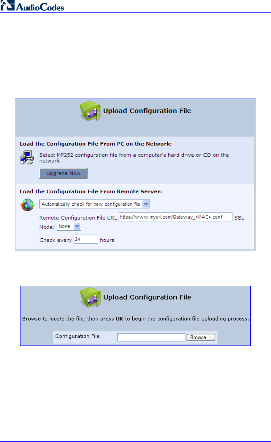
MP252 Multimedia Home Gateway 310 Document #: LTRT-23504
User's Manual
18.4.1 Uploading from PC on the Network
The procedure below describes how to upload a configuration file from a PC on the network
to MP252.
¾ To upload a configuration file to MP252 from a PC on the network:
1. Click the Upload Configuration File; the screen 'Upload Configuration File' opens.
Figure 18-8: Upload Configuration File
2. Under the 'Load the Configuration File From a PC on the Network' group, click Upgrade
Now; the screen 'Upload Configuration File' opens.
Figure 18-9: Loading Configuration File from a PC on the Network
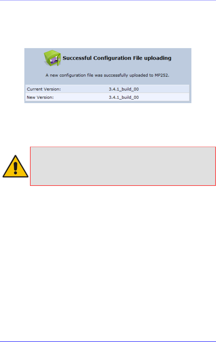
MP252 Multimedia Home Gateway 18. Maintenance
Version 3.4.0 311 June 2011
3. Enter the path of the configuration file or click Browse and navigate to the configuration
file on your PC.
4. Click OK; the file starts loading from the PC to your MP252. When loading is complete,
the screen 'Successful Configuration File Loading' opens, prompting you to confirm
configuration file load.
Figure 18-10: Successful Configuration File Uploading
5. Click OK to confirm; the upgrade process commences and takes a couple of minutes to
complete. At the conclusion of the file load process, the MP252 automatically reboots.
When the MP252 completes the reboot, the new configuration file is applied and the
‘Login’ screen appears, prompting you to login again.
6. Login with your username and password.
Note: During the load process, it is recommended not to power down MP252 nor stop
the file load process to avoid damage to the main firmware. However, if you do,
MP252 runs a recovery firmware image (also stored on its flash memory).
Except for the analog or VoIP interfaces, the recovery image supports all
interfaces and enables MP252 to reconnect to the Internet and then download
the primary software.
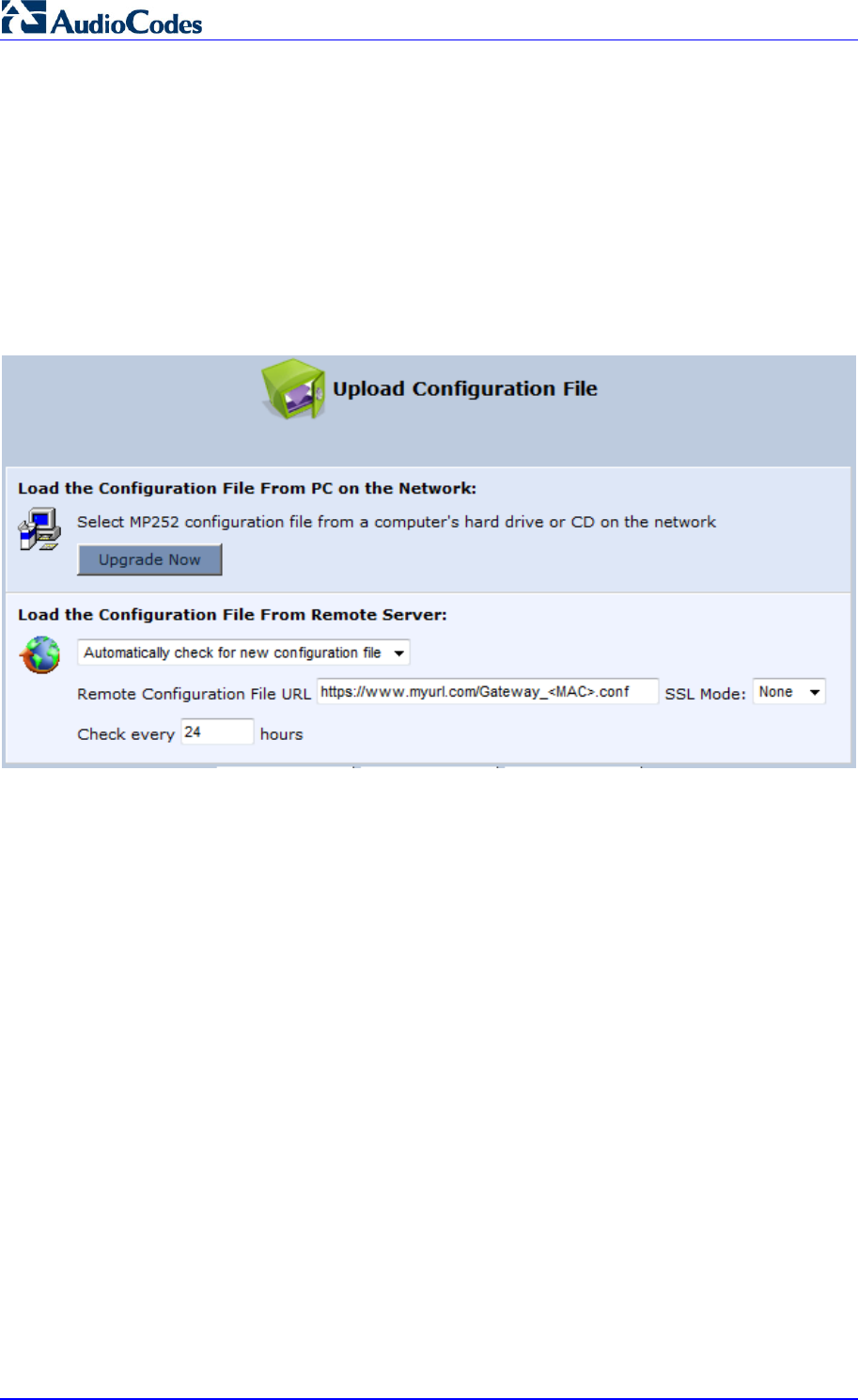
MP252 Multimedia Home Gateway 312 Document #: LTRT-23504
User's Manual
18.4.2 Uploading from a Remote Server
The procedure below describes how to upload a configuration file to MP252 from a remote
server. This allows you to keep your configuration up-to-date, by performing daily checks for
a newer configuration file each time MP252 restarts (i.e., automatic update), or manually
checking for a newer configuration file.
¾ To upload MP252's configuration file from a remote server:
1. Click the Upload Configuration File; the screen 'Upload Configuration File' opens.
Figure 18-11: Upload Configuration File
2. Under the 'Load the Configuration File From Remote Server' group, select the checking
method and interval:
• Automatically check for new configuration file
• Automatic configuration file check disabled
3. In the 'Remote Configuration File URL' field, enter the URL address of the remote server
where the configuration file is located. The URL format is as follows:
protocol://server/filename.<conf/ini>, for example:
• ftp://10.10.10.10/MP20x_<MAC>.conf
• http://20.20.20.20/MP20x_<MAC>.ini
Where <MAC> is the MAC address of MP252's WAN.
4. In the 'Check every' field, enter the interval (in hours) for which MP252 periodically
checks for a new configuration file. If set to 0, MP252 checks only once for a new
configuration file, and this occurs after it restarts.
5. From the ‘SSL Mode’ drop-down list, select the type of Secure Socket Layer (SSL)
certificate's validation method for accessing the remote server using HTTPS for the
following purposes: downloading a new firmware file, downloading a new configuration
file, and TR-069. Upon connection, MP252 validates the server's certificate using the
selected method:
• None: Do not validate the server's certificate (if you do not have a certificate).
• Chain: Validate the entire certificate chain (if you have a certificate, but not
necessarily signed by a root CA).
• Direct: Ensure that the server's certificate is signed by the root certificate (CA).
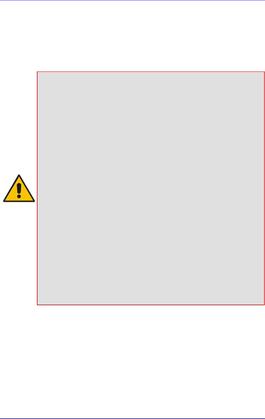
MP252 Multimedia Home Gateway 18. Maintenance
Version 3.4.0 313 June 2011
6. Click OK; the download process begins. When downloading completes, a confirmation
screen appears, prompting you to confirm loading the new version.
7. Click OK to confirm. The upgrade process begins and takes about one minute to
complete. At the conclusion of the upgrade process, MP252 automatically reboots and
the new software version runs.
If a new version is unavailable, click the Check Now button to perform an immediate
check (instead of waiting for the next scheduled one). The screen displays a green
"Check in progress..." message.
Notes:
• For additional security, MP252 can be configured to use HTTPS client-server
certification when connecting to a remote server (see Section 13.3 on page 192).
• The configuration file can have one of the following two formats: a hierarchical
conf file (indicated by file extension *.conf) or a flat ini file (indicated by file
extension .ini).
• The parameter ‘/rmt_config/version’ defines the version of the configuration file.
MP252 uses the new configuration file only if the version that is defined in this file
is later than the current version. By default, the ‘version’ is set to 0. This means
that each time Service Providers’ operations personnel require MP252 to
download a new configuration file, they need to increment the ‘version’ paramete
r
in the new file (in the .conf file, the ‘version’ parameter is under the section
‘rmt_config’). To simplify the procedure, it is possible to use the current date in
YYYYMMDD format as the version field.
• The remote configuration file must include only a subset of the complete
MP20x.conf file. A recommended procedure is to start with a MP252 restored to
its factory settings, modify using the embedded Web server the parameters that
should appear in the remote configuration file, and then upload (save) the
configuration file. You must save only the modified parameters, as described in
'Remote Administration' on page 253.
• The string <MAC> enables the ISP to pre-configure all its deployed MP252s with
the same URL and file details (under rmt_config/url) and still have each MP252
download its unique configuration file. Once the URL is configured with the string
<MAC>, MP252 that is trying to update its configuration file automatically
replaces <MAC> with its own unique MAC address. For example, if there’s a
MP252 with a WAN MAC address 00:01:02:03:04:05, the ISP can configure the
url to http://myserver.com/my_conf_file_<MAC>.conf - and place a file called
‘my_conf_file_00_01_02_03_04_05.conf’ on the server.
• Downloading a configuration file from a remote server can also be performed
from the CLI:
1) Using Telnet, access MP252, and then enter the user name and password.
2) Enter the command rmt_config, for example:
rmt_config –u http://myserver.com/my_conf_file.conf
3) Enter rmt_config without any arguments for more help information.
18.4.3 Encrypting a Configuration File Using CLI
Encrypted files include the file name extension *.cfx (instead of *.cfg) or *.inx (instead of *.ini).
After MP252 loads the encrypted file from the HTTP server, it automatically identifies the
encrypted file by its file name extensions *.cfx or *.inx, and subsequently decrypts the file
before saving it to flash memory.
The following procedure describes how to encrypt configuration files.
¾ To encrypt a configuration file:
Run the following CLI shell command (on Linux or Windows PC with OpenSSL
installed):
MP252 Multimedia Home Gateway 314 Document #: LTRT-23504
User's Manual
openssl des3 -in <original file> -out <encrypted file> -k
<password> -S <salt value>
Where,
• <original file> is the original clear-text configuration file (*.cfg or *.ini file).
• <encrypted file> is the output file (an encrypted *.cfx or *.inx file).
• <password> is the password that is used to encrypt the file.
• <salt value> is the 8 bytes of a special key value that is combined with the
password. The format is 16 hexadecimal digits [0-9,A-F].
An example of this command is shown below:
openssl des3 -in c:\temp\try_enc_conf.cfg -out
c:\temp\try_enc_conf.cfx -k MyPassword123456 -S 0123456789ABCDEF
Notes:
• You can choose any <salt value> – MP252 does not have to know about it.
• A password can be pre-configured in MP252, using the following CLI
command: rg_conf_set_obscure /rmt_config/password
<password>
• You can also define the password in a configuration file that you download
from the server.
• If you don’t define a password in the configuration file, a default password is
used. Different default passwords are defined per customer, according to
the config-file url hostname.
MP252 Multimedia Home Gateway 18. Maintenance
Version 3.4.0 315 June 2011
18.4.4 Automatic Upload using SIP NOTIFY Message
You can enable automatic configuration update for MP252 from a remote server, using the
SIP NOTIFY message. The contents of the configuration file can initiate (“push”) the remote
server to update MP252 to a desired configuration version.
¾ To “push” a configuration file when a change of parameter is needed:
1. Create a new configuration file with the required change.
2. Place the file on the HTTP server.
3. Send the SIP NOTIFY message to MP252; MP252 integrates the contents of the new
file and reboots.
¾ To “push” a configuration file and initiate an upgrade or downgrade:
1. Create a new configuration file that includes two important entries:
a. In rg_conf/rmt_upd/chech_sync_version, configure the details of the version to
which you want MP252 to upgrade or downgrade, for example:
(rmt_upd
(check_sync_version(2.6.0_build_1))
)
b. You may need to update the URL address from where MP252 is downloading the
firmware (the path is configured in rmt_upd/url).
Note: In the case of a downgrade, the service provider MUST provide a configuration
file based on a template that matches the version to which the MP252 is
downgrading.
2. Place the file on the HTTP server.
3. Send the SIP NOTIFY message to MP252; MP252 integrates the contents of the new
file and reboots. After rebooting, MP252 compares the currently running version with
the version which is configured in rmt_upd/chech_sync_version and then determines
whether to connect to the rmt_upd/url for downloading the new *.rmt file. Once the file is
downloaded, its headers are parsed, and only if it represents the same version which
was configured in the value of rmt_upd/chech_sync_version, does the
upgrade/downgrade process begin.
18.5 Firmware Upgrade
MP252 provides a built-in mechanism for upgrading its software image. There are two
methods for upgrading the software image:
Upgrading from a Computer on the Network: This method uses a software image file
that is pre-downloaded on a PC's disk drive or located on an accompanying CD. (See
Section 18.5.1 on page 317.)
Upgrading from the Internet: This method also referred to as 'Remote Update',
upgrades your firmware by remotely downloading an updated software image file. (See
Section 18.5.2 on page 318.)
MP252 provides a flash memory of 8 MB, which is capable of storing two firmware images. In
addition to the primary firmware, MP252 also stores a recovery firmware, which is used only
if the primary image is missing or damaged (e.g. if the user unplugs the power during
firmware upgrade). Except for the analog or VoIP interfaces, the recovery image supports all
interfaces and enables MP252 to reconnect to the Internet and download the primary
firmware.
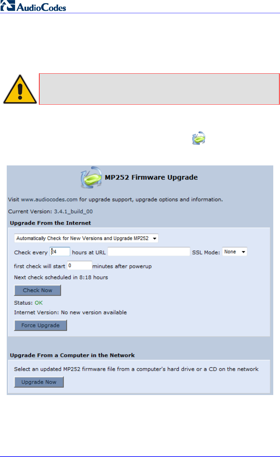
MP252 Multimedia Home Gateway 316 Document #: LTRT-23504
User's Manual
18.5.1 Upgrading from a Computer on the Network
The procedure below describes how to upgrade MP252 from a software image file located on
a local computer or network.
Note: You can only use files with an *.rmt extension when performing the firmware
upgrade procedure.
¾ To upgrade MP252 software image using a locally available .rmt file:
1. In the 'Advanced' screen, click the Firmware Upgrade icon; the ‘MP252 Firmware
Upgrade' screen appears.
Figure 18-12: MP252 Firmware Upgrade Screen
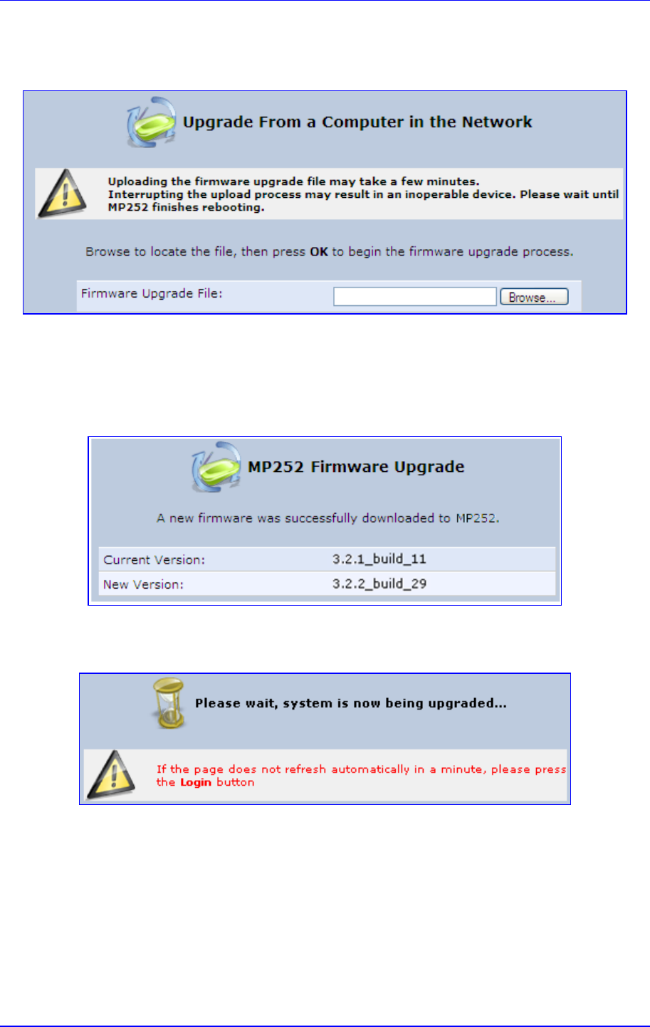
MP252 Multimedia Home Gateway 18. Maintenance
Version 3.4.0 317 June 2011
2. Under the Upgrade From a Computer in the Network group, click the Upgrade Now
button; the 'Upgrade From a Computer in the Network' screen appears.
Figure 18-13: Upgrade From a Computer in the Network Screen
3. In the 'Firmware Upgrade File' field, enter the path to the software image file or click
Browse and navigate to the rmt file on your PC.
4. Click OK; the MP252 uploads the file from your PC. When loading is complete, you are
prompted to confirm upgrade to the new version.
Figure 18-14: Confirming Firmware Upgrade Screen
5. Click OK to confirm; the upgrade process commences (a few minutes).
Figure 18-15: Upgrading in Progress Screen
At the conclusion of the upgrade process, MP252 automatically reboots and the new
software version now runs on MP252, maintaining your configurations and settings.
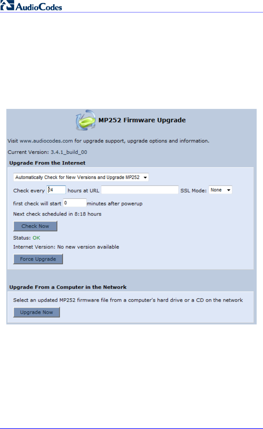
MP252 Multimedia Home Gateway 318 Document #: LTRT-23504
User's Manual
18.5.2 Upgrading From the Internet
The Remote Update mechanism helps you keep your software image up-to-date, by
performing routine daily checks for newer software versions, as well as letting you perform
manual checks. These updates are from a user-defined URL.
¾ To upgrade MP252's software image from the Internet:
1. In the 'Advanced' screen, click the Firmware Upgrade icon; the ‘MP252 Firmware
Upgrade' screen appears.
Figure 18-16: Advanced - Firmware and Configuration Upgrade

MP252 Multimedia Home Gateway 18. Maintenance
Version 3.4.0 319 June 2011
2. Under the Upgrade From the Internet group, select the utility's checking method and
interval:
• Automatically Check for New Versions and Upgrade MP252: MP252
automatically checks for new versions every user-defined interval (defined in the
'Check every' field) at the URL address defined in the 'URL' field. You can define
the time (in minutes) after which the first check commences after MP252 is reset.
• Automatically Check for New Versions and Notify via Email:
• Automatic Check Disable: MP252 checks for a new version at the URL address
defined in the 'URL' field, when you click the Check Now button.
The result of the last performed check is displayed between the Check Now and Force
Upgrade buttons, indicating whether a new version is available or not.
3. If a new version is available:
a. Click the Force Upgrade button. A download process begins. When downloading
is complete, you are prompted to confirm upgrade to the new version.
b. Click OK to confirm. The upgrade process begins and takes about one minute to
complete. At the conclusion of the upgrade process, MP252 automatically reboots
with the new software version.
4. If a new version is unavailable:
a. Click the Check Now button to perform an immediate check (instead of waiting for
the next scheduled one). The screen displays the "Check in progress" message.
b. Click the Refresh button until the check is complete and the result is displayed.
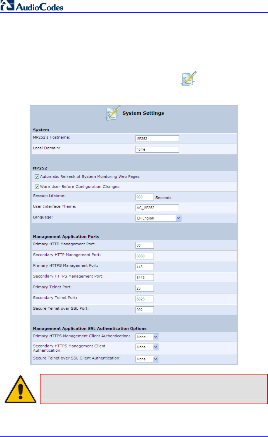
MP252 Multimedia Home Gateway 320 Document #: LTRT-23504
User's Manual
18.6 System Settings
The 'System Settings' screen allows you to configure various MP252 system and
management parameters.
¾ To configure MP252 system and management settings:
1. In the 'Advanced' screen, click the System Settings icon; the 'System Settings'
screen appears.
Figure 18-17: System Settings Screen (Only Partial View due to Screen Size)
Note: Due to the size of the ‘System Settings’ screen, the figure above provides only
a partial display.
2. Under the System Settings group, configure the following:

MP252 Multimedia Home Gateway 18. Maintenance
Version 3.4.0 321 June 2011
• In the ‘MP252’s Hostname' field, enter the MP252's host name. The host name is
the MP252's URL address.
• In the 'Local Domain' field, enter your network's local domain.
3. Under the MP252 group, do the following:
• Automatic Refresh of System Monitoring Web Pages: select this check box to
enable automatic refreshing of system monitoring Web interface pages.
• Warn User Before Network Configuration Changes: select this check box to
activate user warnings before network configuration changes take effect.
• Session Lifetime: duration of idle time (in seconds) in which the Web session
remains active. When this duration times out, you must re-login.
• User Interface Theme: enter an alternative GUI theme name.
• Language: select a language for the Web interface GUI.
4. Under the Management Application Ports group, define the following ports:
• Primary/secondary HTTP management ports
• Primary/secondary management HTTPS ports
• Primary/secondary Telnet ports
• Secure Telnet over SSL ports
5. Under the Management Application SSL Authentication Options group, configure
whether the following is required:
• Primary/Secondary HTTPS Management Client Authentication
• Secure Telnet over SSL Client Authentication
6. Under the System Logging group, do the following:
• System Log Buffer Size: size of the system log buffer in kilobytes.
• Remote System Notify Level: MP252 sends notifications to a remote host (None,
Error, Warning, Information)
• Persistent System Log: saves the system log to MP252 flash memory. This
prevents the system log from being erased when MP252 reboots.
7. Under the Security Logging group, do the following:
• Security Log Buffer Size: size of the security log buffer in Kilobytes
• Remote Security Notify Level: None, Error, Warning, Information
• Persistent Security Log: saves the security log to the flash. This prevents the
security log from being erased when MP252 reboots.
Note: Do not leave the persistent logging feature enabled permanently, as continuous
writing of the log files to the flash memory reduces MP252's performance.

MP252 Multimedia Home Gateway 322 Document #: LTRT-23504
User's Manual
8. Under the Outgoing Mail Server group, do the following:
• Server: hostname of your outgoing (SMTP) server.
• From Email Address: Each email requires a 'from' address and some outgoing
servers refuse to forward mail without a valid 'from' address for anti-spam reasons.
• Port: port used by your outgoing mail server.
• Server Requires Authentication: If your outgoing mail server requires
authentication, select this check box and enter your user name and password in
the subsequent 'User Name' and 'Password' fields respectively.
To define email notifications per User to receive indications of system and security
events, see Section 4.4 on page 40.
9. The Swap group configures the Swap feature that enables you to free a portion of the
RAM by creating a swap file on the storage device connected to MP252. This is
especially useful for platforms with a small RAM. To activate this feature:
a. Verify that a storage device is connected to MP252.
b. Select the 'Enabled' check box.
c. In the 'Swap Size' field, enter a swap file size in megabytes.
d. Click Apply; a swap file is created on the storage device and the read-only ‘Status’
field changes to “Ready”.
10. Under the Host Information group, select the ‘Enable Auto Detection of Host Services’
check box to enable MP252 to auto-detect its LAN hosts' properties, available services,
traffic statistics, and connections.
11. Under the Installation Wizard group, select the ‘Use Installation Wizard Pre-configured
Values’ check box to have the wizard skip the steps for which parameters had been
preconfigured and saved in the factory settings file (rg_factory).

MP252 Multimedia Home Gateway 18. Maintenance
Version 3.4.0 323 June 2011
18.7 Reboot
The procedure below describes how to reboot MP252.
¾ To reboot MP252:
1. In the 'Advanced' screen, click the Reboot icon; the 'Reboot' screen appears.
Figure 18-18: Reboot Screen
2. Click OK to reboot MP252. This may take up to one minute.
3. To re-enter the Web interface after rebooting MP252, refresh your Internet browser.
You can also reboot MP252 using a manual procedure, as described below:
¾ To manually reboot MP252:
Insert a paper clip (or any other similar pointed object) into the Reset pin-hole button
located on the rear panel of MP252, and keep the button pressed for at least 1 second
(but no more than 5 seconds); the MP252 reboots.
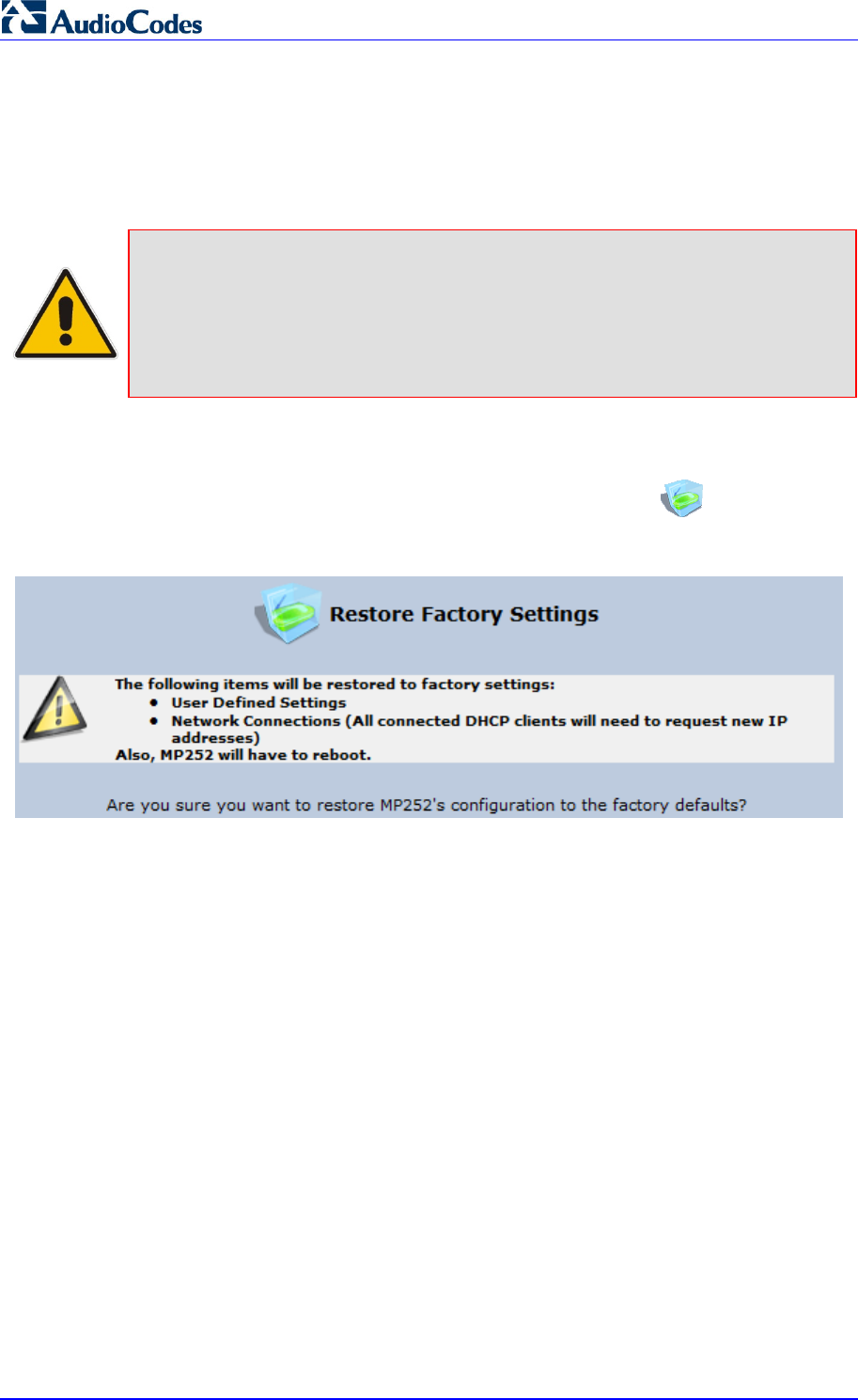
MP252 Multimedia Home Gateway 324 Document #: LTRT-23504
User's Manual
18.8 Restoring Factory Settings
You can restore MP252 to factory default settings. This is useful when, for example, you are
initially creating a new network or when you cannot recall changes made to the network.
Notes:
• If you are accessing MP252's Web interface from the WAN, restoring
factory default settings causes the connection with MP252 to be lost, since
access to the Web interface from the WAN is blocked by default.
• All Web-based management settings and parameters are restored to thei
r
default values. This includes the administrator username and password
¾ To restore MP252 to default settings:
1. In the 'Advanced' screen, click the Restore Factory Settings icon; the 'Restore
Factory Settings' screen appears.
Figure 18-19: Restore Factory Settings Screen
2. Click OK to restore MP252's factory default settings.
If the MP252 Web interface cannot be accessed (for example, if the password is unknown or
if the LAN is disabled), you can restore default settings manually, as described below:
¾ To manually restore MP252 to default settings:
Insert a paper clip (or any other similar pointed object) into the Reset pin-hole button
located on the rear panel of MP252, and keep the button pressed for at least seven
seconds. While MP252 sets all its parameters to default, the Status, Broadband, and
Phone LEDs blink red. After this, the Status LED is lit steady red while MP252 reboots.

MP252 Multimedia Home Gateway 19. Diagnostics and Performance Monitoring
Version 3.4.0 325 June 2011
19 Diagnostics and Performance Monitoring
The System Monitoring menu displays important system information and includes the
following main tab screens:
Network Connections – see Section 19.2 on page 331
System Log – see Section 19.2.2 on page 332
CPU – see Section 19.2.3 on page 332
VoIP – see Section 19.2.4 on page 335
Internet Connection Utilization - see Section 19.2.5 on page 335
19.1 Diagnostics
The Diagnostics icon allows you to test network connectivity. In addition, it allows you
to view statistics such as the number of packets transmitted and received, round-trip time,
and success status. The test tools are platform-dependent and are not available
simultaneously.
The Diagnostics icon displays the ‘Diagnostics’ screen, as described below.
¾ To access the 'Diagnostics' screen:
In the 'Advanced' screen, click the icon.
Figure 19-1: Diagnostics Screen
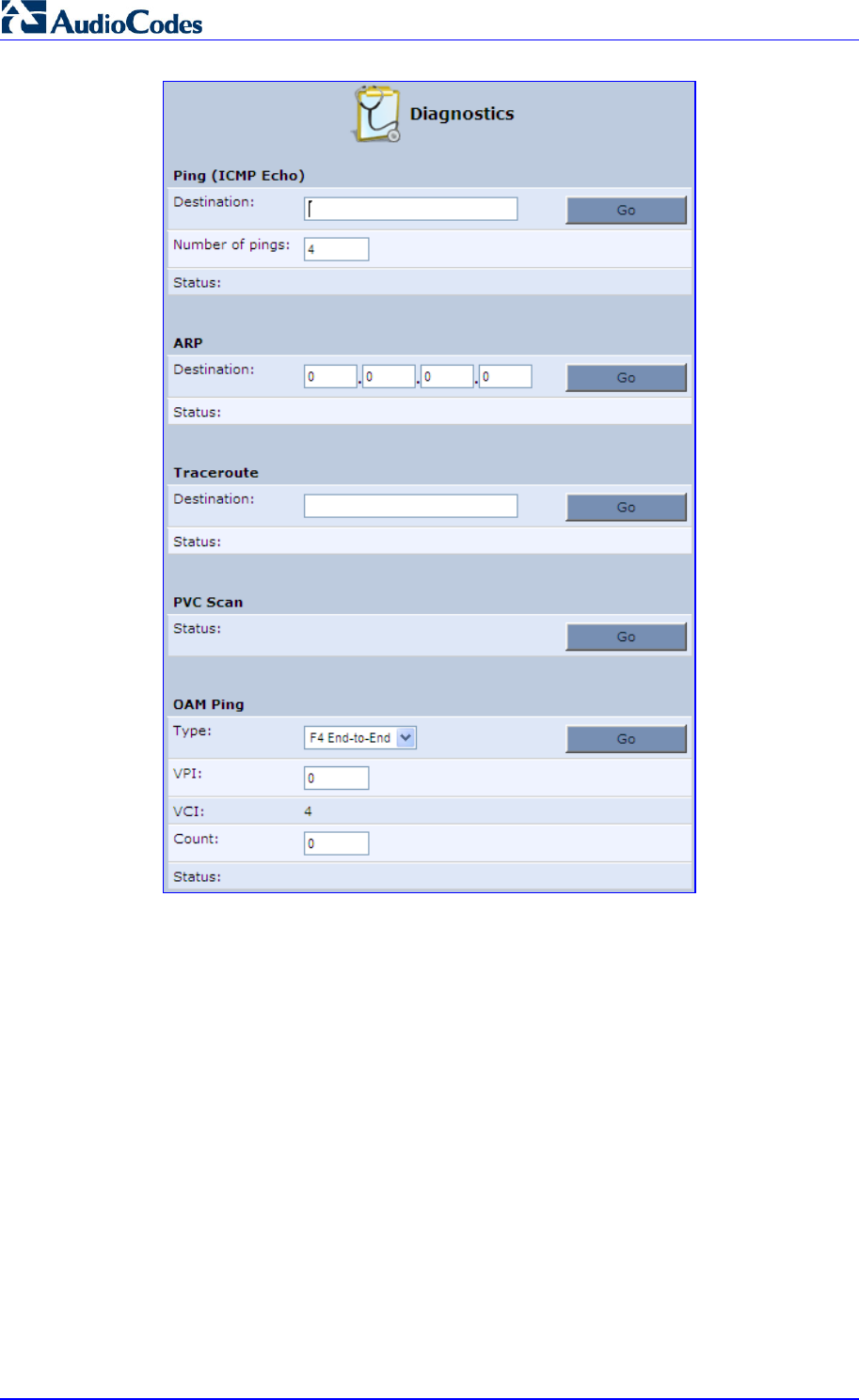
MP252 Multimedia Home Gateway 326 Document #: LTRT-23504
User's Manual
19.1.1 Running a Ping Test
The procedure below describes how to run a ping (ICMP) test in the ‘Diagnostics’ screen.
This test is done under the Ping (ICMP Echo) group.
¾ To run a ping test:
1. In the 'Destination' field, enter the IP address or URL to be tested.
2. In the 'Number of pings' field, enter the number of pings you want to perform.
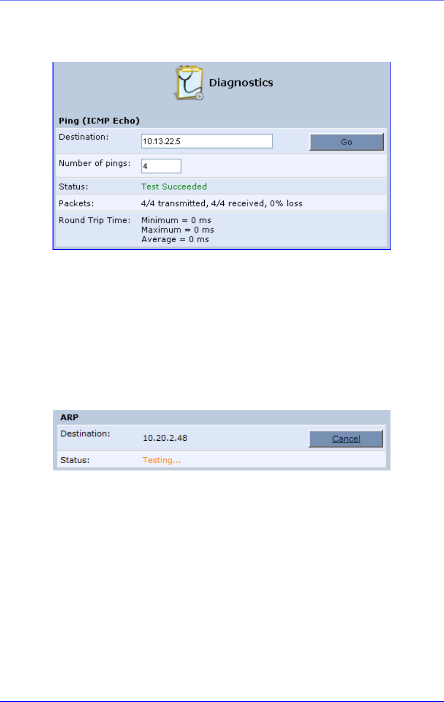
MP252 Multimedia Home Gateway 19. Diagnostics and Performance Monitoring
Version 3.4.0 327 June 2011
3. Click Go; after a few seconds, diagnostic statistics are displayed. If no new information
is displayed, click the Refresh button.
Figure 19-2: Running a Ping Test
19.1.2 Running an ARP Test
The ARP test is used to query the physical address (i.e., MAC) of a host.
The procedure below describes how to run an Address Resolution Protocol (ARP) test in the
‘Diagnostics’ screen. This test is done under the ARP group.
¾ To run an ARP test:
1. in the 'Destination' field, enter the IP address of the target host.
2. Click Go; after a few moments, diagnostic statistics is displayed. If no new information is
displayed, click Refresh.
Figure 19-3: Running an ARP Test
19.1.3 Running a Traceroute
The procedure below describes how to run a traceroute test in the ‘Diagnostics’ screen. This
test is done under the Traceroute group.
¾ To run a traceroute:
1. In the 'Destination' field, enter the IP address or URL to be tested.
2. Click Go; a traceroute commences, constantly refreshing the screen.
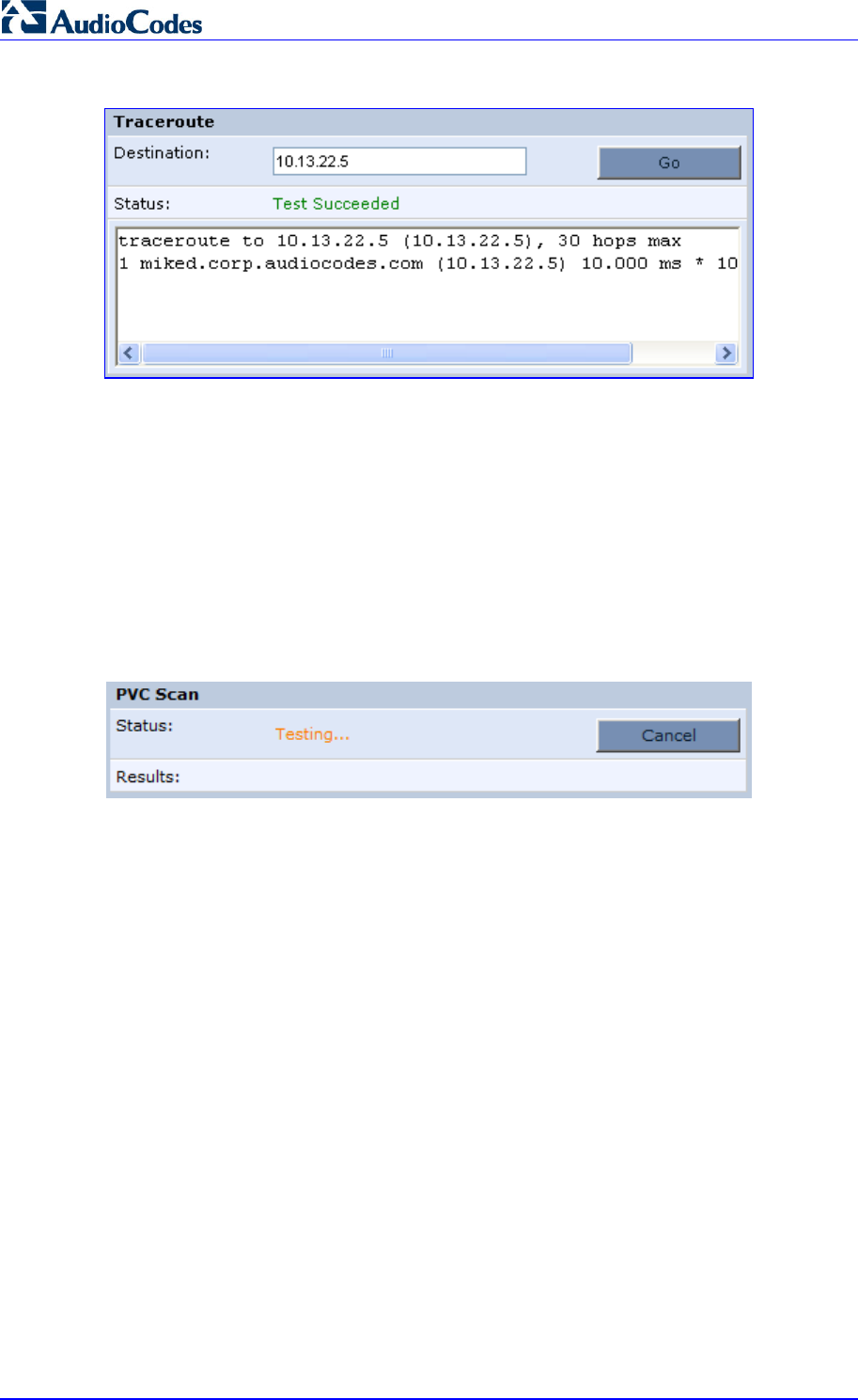
MP252 Multimedia Home Gateway 328 Document #: LTRT-23504
User's Manual
Figure 19-4: Running a Traceroute
3. To stop the trace and view the results, click Cancel.
19.1.4 Running a PVC Scan Test
The procedure below describes how to run a Permanent Virtual Circuit (PVC) scan in the
‘Diagnostics’ screen.
¾ To run a PVC scan:
Under the PVC Scan group, click Go; in a few moments, diagnostic statistics is
displayed. If no new information is displayed, click Refresh.
Figure 19-5: Running a PVC Scan
19.1.5 Running an OAM Ping Test
The Operation and Maintenance (OAM) ping test checks the status of a Virtual Channel (VC)
of the Asynchronous Transfer Mode (ATM) connection to the remote Network Access
Concentrator (NAC). Each of the ATM's virtual channels has an address that consists of a
Virtual Path Indicator (VPI) and Virtual Channel Indicator (VCI). The OAM ping test sends a
request, either a VP loopback (F4) or a VC loopback (F5), and receives a reply from the NAC
at the other end of the ATM connection.
The procedure below describes how to run an OAM Ping test in the ‘Diagnostics’ screen.
This test is done under the OAM Ping group.
¾ To run an OAM ping test:
1. From the ‘Type’ drop-down list, select the type of OAM ping to run:
• F4 End-to-End
• F4 Segment
• F5 End-to-End
• F5 Segment
2. In the 'VPI' field, enter the channel's VPI value.
3. In the ‘VCI’ field, enter the channel's VCI value. This is applicable only if you are
checking the VC loopback (F5).
4. In the 'Count' field, enter a number of the ping packets sent to the destination address.
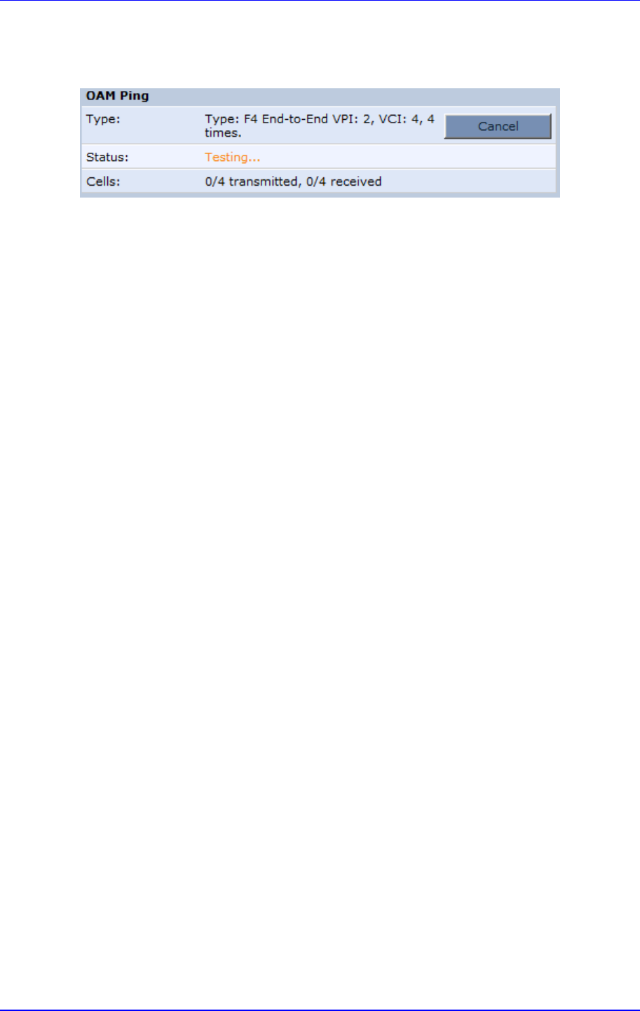
MP252 Multimedia Home Gateway 19. Diagnostics and Performance Monitoring
Version 3.4.0 329 June 2011
5. Click Go; in a few moments, diagnostic statistics is displayed. If no new information is
displayed, click Refresh.
Figure 19-6: Running an OAM Ping Test
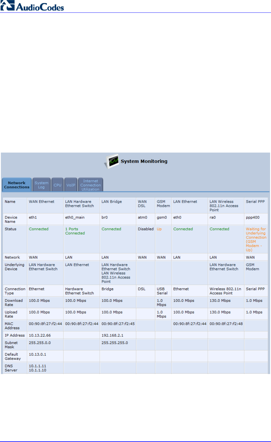
MP252 Multimedia Home Gateway 330 Document #: LTRT-23504
User's Manual
19.2 Performance Monitoring
This section describes how to view the MP252 performance status.
19.2.1 Network Connections
MP252 constantly monitors traffic within the local network and between the local network and
the Internet. You can view up-to-the-second statistical information about data received from
and transmitted to the Internet (WAN) and about data received from and transmitted to
computers in the local network (LAN).
¾ To view network connections:
1. From the menu bar, click the System Monitoring menu.
2. Select the Network Connections tab.
Figure 19-7: Network Connections Screen
Click the Refresh button to update the display or click the Automatic Refresh On button to
automatically refresh the displayed parameters. To reset the counters, click the Reset
Statistics button.
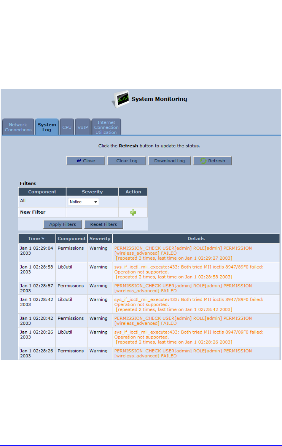
MP252 Multimedia Home Gateway 19. Diagnostics and Performance Monitoring
Version 3.4.0 331 June 2011
19.2.2 System Log
The ‘System Log’ screen displays a list of the most recent activity that has occurred on
MP252.
¾ To view the system log:
1. From the menu bar, click the System Monitoring menu.
2. Select the System Log tab.
Figure 19-8: System Log Screen
To update the display, click the Refresh button. To clear the list of logged events, click the
Clear Log button. To save the logged events to a file (comma-separated values file) on your
PC, click the Download Log button.
19.2.3 CPU
The 'CPU' screen displays the following system parameters:
Gateway ID:

MP252 Multimedia Home Gateway 332 Document #: LTRT-23504
User's Manual
System Has Been Up For: Time that has passed since MP252 was last started.
Load Average: Average number of processes that are either in a runnable or
uninterruptible state. A process in the runnable state is either using the CPU or waiting
to use the CPU. A process in the uninterruptible state is waiting for I/O access, e.g.
waiting for the disk. The averages are taken over the three time intervals. The meaning
of the load average value varies according to the number of CPUs in the system. This
means for example, that a load average of 1 on a single-CPU system means that the
CPU was loaded all the time, while on a 4-CPU system this means that the CPU was
idle 75% of the time.
Processes: Processes currently running on MP252 and their virtual memory usage.
The amount of memory granted for each process is displayed as follows:
• Total Virtual Memory (VmData): Amount of memory currently utilized by the
running process.
• Heap size (VmSize): Total amount of memory allocated for the running process.
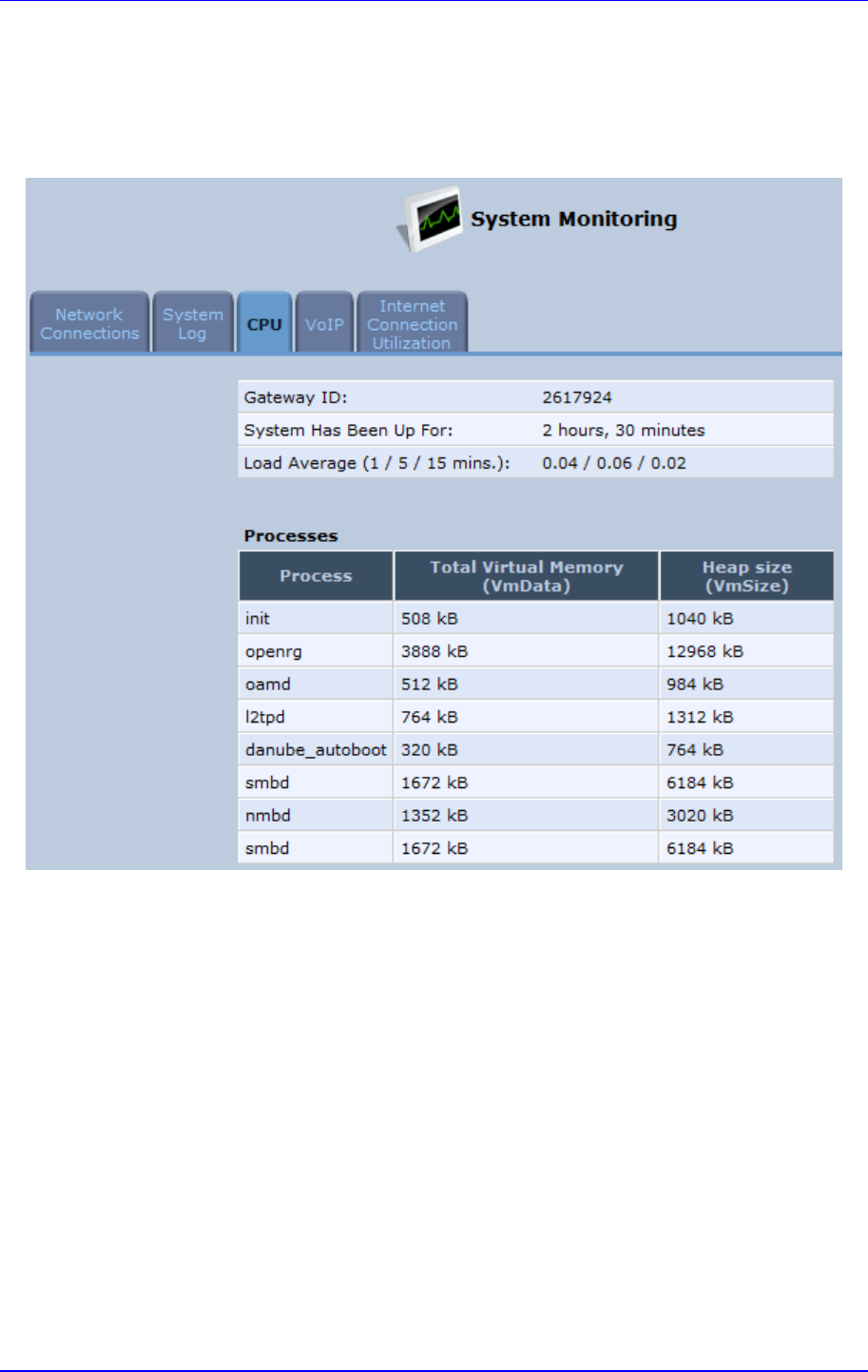
MP252 Multimedia Home Gateway 19. Diagnostics and Performance Monitoring
Version 3.4.0 333 June 2011
¾ To view the CPU statistics:
1. From the menu bar, click the System Monitoring menu.
2. Select the CPU tab.
Figure 19-9: CPU Screen
By default, the screen is automatically refreshed. To disable automatic refresh, click
Automatic Refresh Off, and then click the Refresh button each time you want to update the
display.
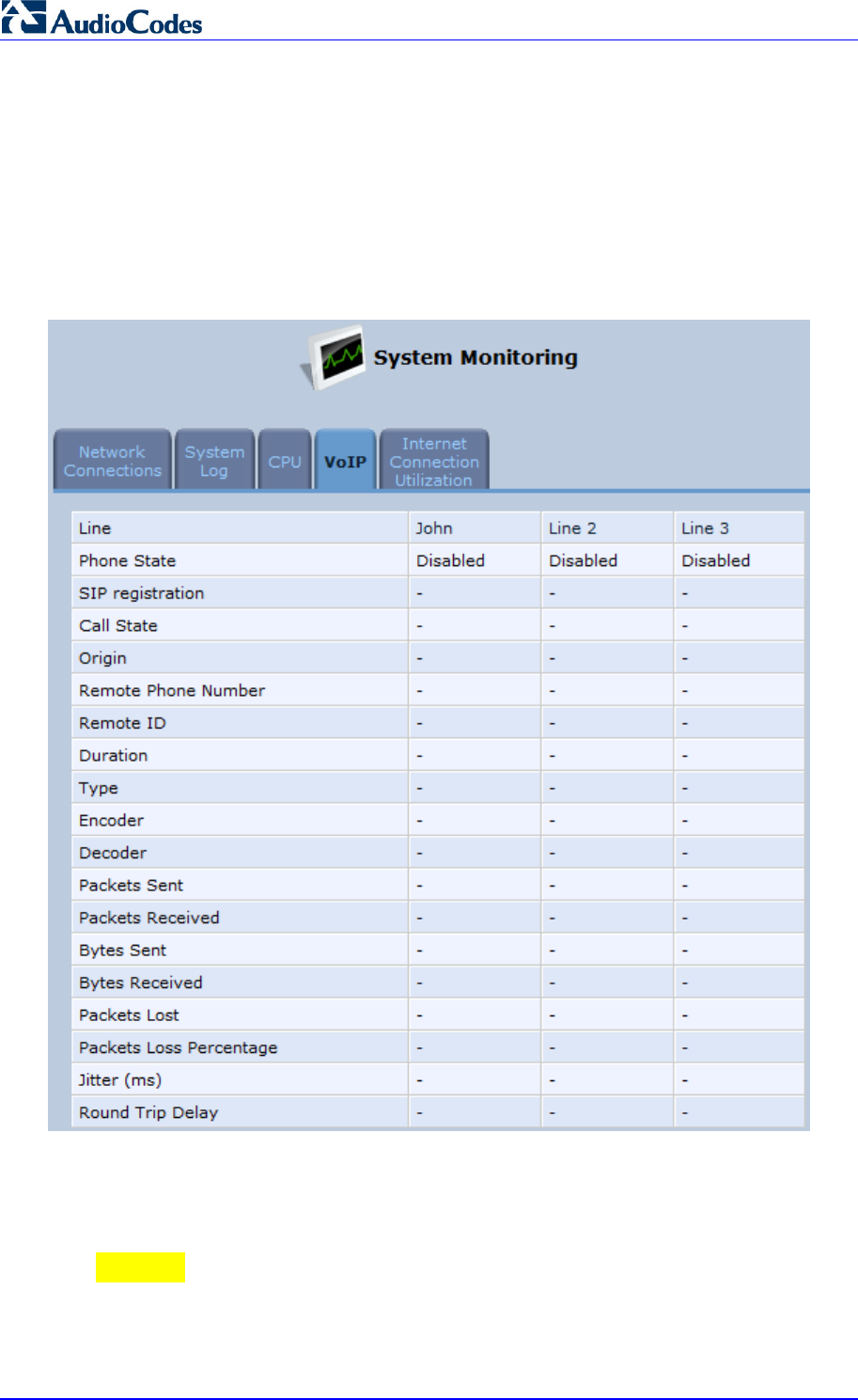
MP252 Multimedia Home Gateway 334 Document #: LTRT-23504
User's Manual
19.2.4 Voice over IP
The ‘VoIP’ screen displays information on VoIP traffic and settings.
¾ To monitor VoIP traffic:
1. From the menu bar, click the System Monitoring menu.
2. Select the VoIP tab.
Figure 19-10: VoIP Screen
By default, the screen is automatically refreshed. To disable automatic refresh, click
Automatic Refresh Off, and then click the Refresh button each time you want to update the
display.
19.2.5 Internet Connection Utilization
The ‘Internet Connection Utilization’ screen displays the Internet connection bandwidth
usage information per computer and application.
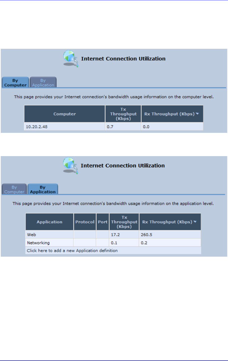
MP252 Multimedia Home Gateway 19. Diagnostics and Performance Monitoring
Version 3.4.0 335 June 2011
¾ To monitor Internet connection usage:
1. From the menu bar, click the System Monitoring menu.
2. Select the Internet Connection Utilization tab. By default, the By Computer tab is
selected.
Figure 19-11: Internet Connection Utilization – By Computer Screen
3. To view bandwidth utilization per application, click the By Application tab.
Figure 19-12: Internet Connection Utilization – By Application Screen
By default, the screen is automatically refreshed. To disable automatic refresh, click
Automatic Refresh Off, and then click the Refresh button each time you want to update the
display.
Part II
DECT Phone
Part II describes the installation and configuration of the MP252 DECT phone, and includes
the following chapters:
Introduction
Safety Instructions
Getting Started
General Phone Operation
Phonebook
Call List
Clock and Alarm
Customizing the Handset
Base Settings
Factory Defaults
Troubleshooting
Note: This part is applicable only to MP252WDNB.

Version 3.4.0 337 July 2011
MP252 Multimedia Home Gateway 20. Introduction
20 Introduction
Part I provides you with step-by-step instructions on how to use your AudioCodes MP252
cordless Digital Enhanced Cordless Telecommunications (DECT) VoIP telephone.
AudioCodes DECT phone offers the following main features:
DECT technology providing high-definition voice quality, security and range
Interference free for crystal clear conversations—no interference with other wireless
networks and other electronic devices
Up to 5 handsets can be registered to the MP252 base station
Call hold
Call transfer
Auto-answer
Call muting
Silent ring mode
Stores dialed, received and missed calls
Last number redial
Hands-free conversations using handset speakerphone
Phone book directory of up to 150 contacts—easy to store and dial
Three-way conference calls between outside call and between handsets
Intercom between handsets
Configurable LCD screen properties–contrast level and background wallpaper
Handset volume control
Built-in alarm clock with snooze
Multi-language support for displaying the LCD screen
Page/handset locator
Selectable ring tones
Keypad lock capability to prevent accidental pressing of keys
Wall-mount bracket included
Comfortable handset size

MP252 Multimedia Home Gateway 338 Document #: LTRT-23504
User's Manual
21 Safety Instructions
Before using your DECT phone, read the following safety instructions:
1. Read and understand all the instructions.
2. Follow all warnings and instructions marked on the product.
3. Unplug this product from the wall outlet before cleaning. Do not use liquid cleaners or
aerosol cleaners. Use a damp cloth for cleaning.
4. Do not use this product near water (for example, near a bath tub, kitchen sink,
swimming pool).
5. Do not overload wall outlets and extension cords as this can result in the risk of fire or
electric shock.
6. Unplug this product from the wall outlet and refer servicing to AudioCodes under the
following conditions:
• When the power supply cord or plug is damaged or frayed.
• If the product does not operate normally by following the operating instructions.
• If the product has been dropped and the cabinet has been damaged.
• If the product exhibits a distinct change in performance.
7. Avoid using a telephone (other than a cordless type) during an electrical storm. There
may be a remote risk of electric shock from lightning.
8. Do not use the telephone to report a gas leak in the vicinity of the leak.
9. Use only the supplied nickel-metal hydride cell (NiMH) rechargeable batteries! The
operation periods for the handsets are only applicable with the default battery
capacities.
10. Use only the supplied 12VDC +/-10%, tolerance, 2A, limited power source wall mount
Class II power supply adapter. Before connecting MP252 to power, ensure that the VAC
ratings match.
11. The use of other battery types or non-rechargeable batteries/primary cells can be
dangerous. These may cause interference and/or unit damages. The manufacturer will
not be held liable for damage arising from such non-compliance.
12. Do not use third-party charging bays. The batteries may be damaged.
13. Please note the correct polarity while inserting the batteries.
14. Do not immerse batteries in water, do not place in fire.
Caution
RISK OF EXPLOSION IF BATTERY IS REPLACED BY AN INCORRECT
TYPE.
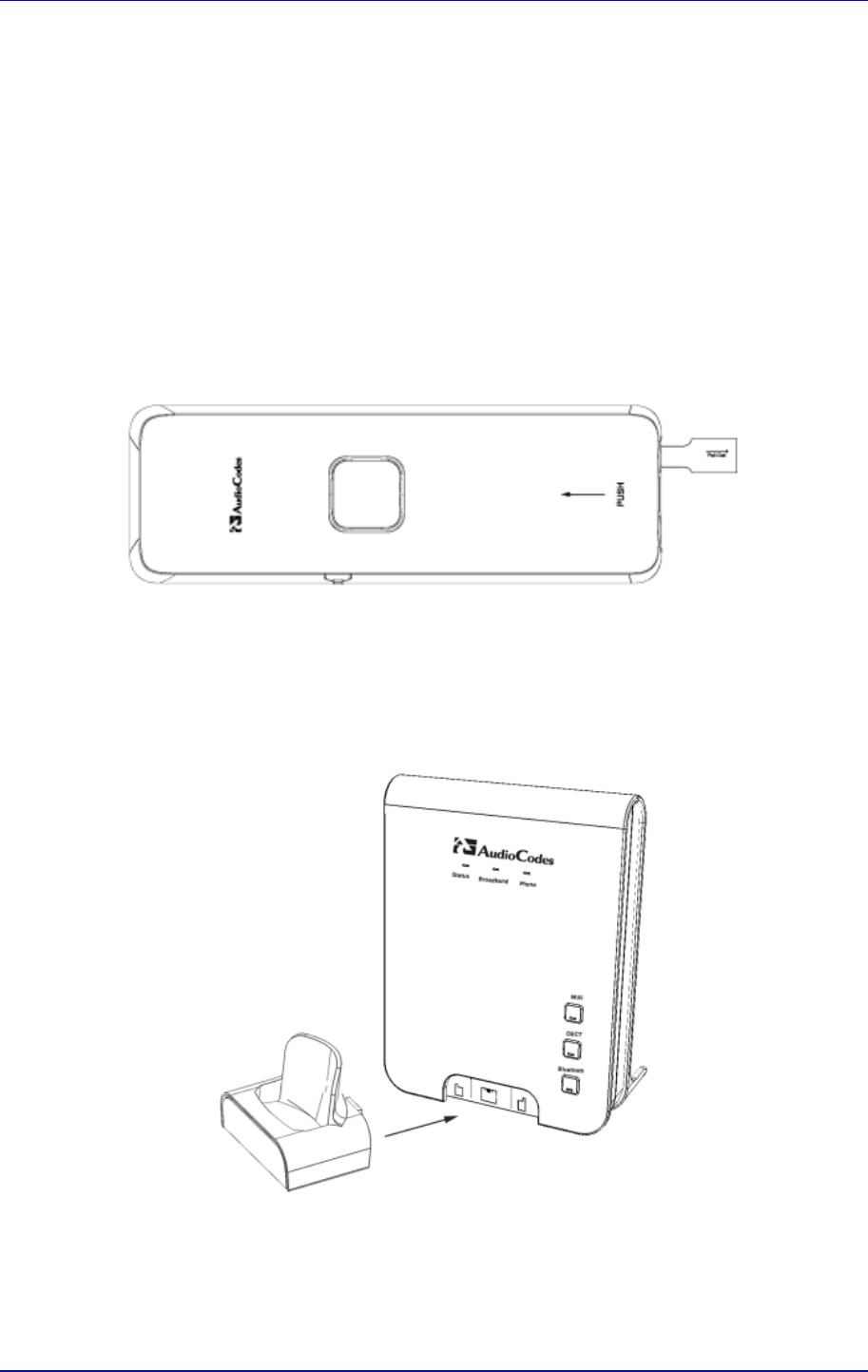
Version 3.4.0 339 June 2011
MP252 Multimedia Home Gateway 22. Getting Started
22 Getting Started
22.1 Installing the DECT Phone
The procedure below describes how to install the DECT phone on the MP252 unit.
¾ To install the DECT phone:
1. The handset is shipped with rechargeable batteries already installed in the battery
compartment. However, a plastic sheath separates the batteries from the handset’s
electrical circuit. Before you can charge the handset, you need to remove this plastic
sheath. On the handset, pull out the plastic tab jutting out from the battery compartment.
This closes the battery circuit and provides power to the handset.
Figure 22-1: Plastic Tab jutting out from Battery Compartment
2. On the lower part of the MP252 front panel, remove the cover protecting the connector
for the handset cradle.
3. Attach the handset cradle to the unit by inserting it into the exposed groove and then
pushing it up so that it clicks on to the connector. Attach the removed cover to the front
of the cradle.
Figure 22-2: Attaching Handset Cradle to MP252 Base Unit
4. Place the handset in the cradle and leave to charge for at least 16 hours prior to initial
use.
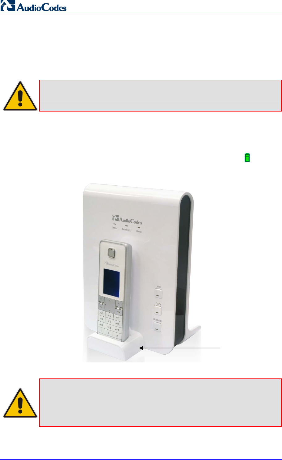
MP252 Multimedia Home Gateway 340 Document #: LTRT-23504
User's Manual
22.2 Powering the Handset
22.2.1 Charging the Handset
Once you have installed the batteries, you need to charge them before initial operation.
Note: Charge the batteries for at least 16 hours before initial use.
¾ To charge the handset:
1. Ensure that the MP252 is connected to power.
2. Place the handset in the charging cradle of the base unit so that the bottom of the phone
sits in the base cradle. When correctly inserted in the cradle, the phone begins
charging, indicated by the display of the charging levels of the battery icon in the
phone's screen. For checking battery level, see Section 22.2.2 on page 342.
Figure 22-3: Handset Charging in Cradle
Notes:
• During a call, if your handset batteries are low, your handset will play a
warning tone. Replace the handset on the base to recharge them.
• Your phone can sound an alert tone when the battery is low. To activate this
alert, see Section 27.3.2 on page 380.
Handset Cradle

Version 3.4.0 341 June 2011
MP252 Multimedia Home Gateway 22. Getting Started
22.2.2 Checking the Battery Level
The battery icon located in the main screen, displays the current battery level, as shown
below:
Handset battery is fully charged.
Handset battery is two-thirds charged.
Handset battery is one-third charged.
Handset battery is empty and needs charging. This icon flashes.
Your handset may power down if it is not charged after the battery is empty. If you are in a
call and the battery is low, an alert tone is sounded. You can enable or disable this alert tone
feature (see Section 27.3.2 on page 380).
22.2.3 Switching the Base Unit On or Off
To operate your phone, the base station must be on. You can turn the base station on or off
as described in the procedure below:
¾ To switch the base on or off:
On the MP252, press the DECT LED button. When the base station is switched off, the
DECT LED is lit red. When switched on, the LED is green or another color depending on
the state of the phone. For a description of the DECT LED, see Section 22.3.3 on page
351.
22.2.4 Switching the Handset On or Off
When you place the handset in the base unit to charge, the handset automatically turns on.
You can turn the handset on or off, as described in the procedure below:
¾ To switch the handset on or off:
On the handset, continually press the button until the handset switches off or on.
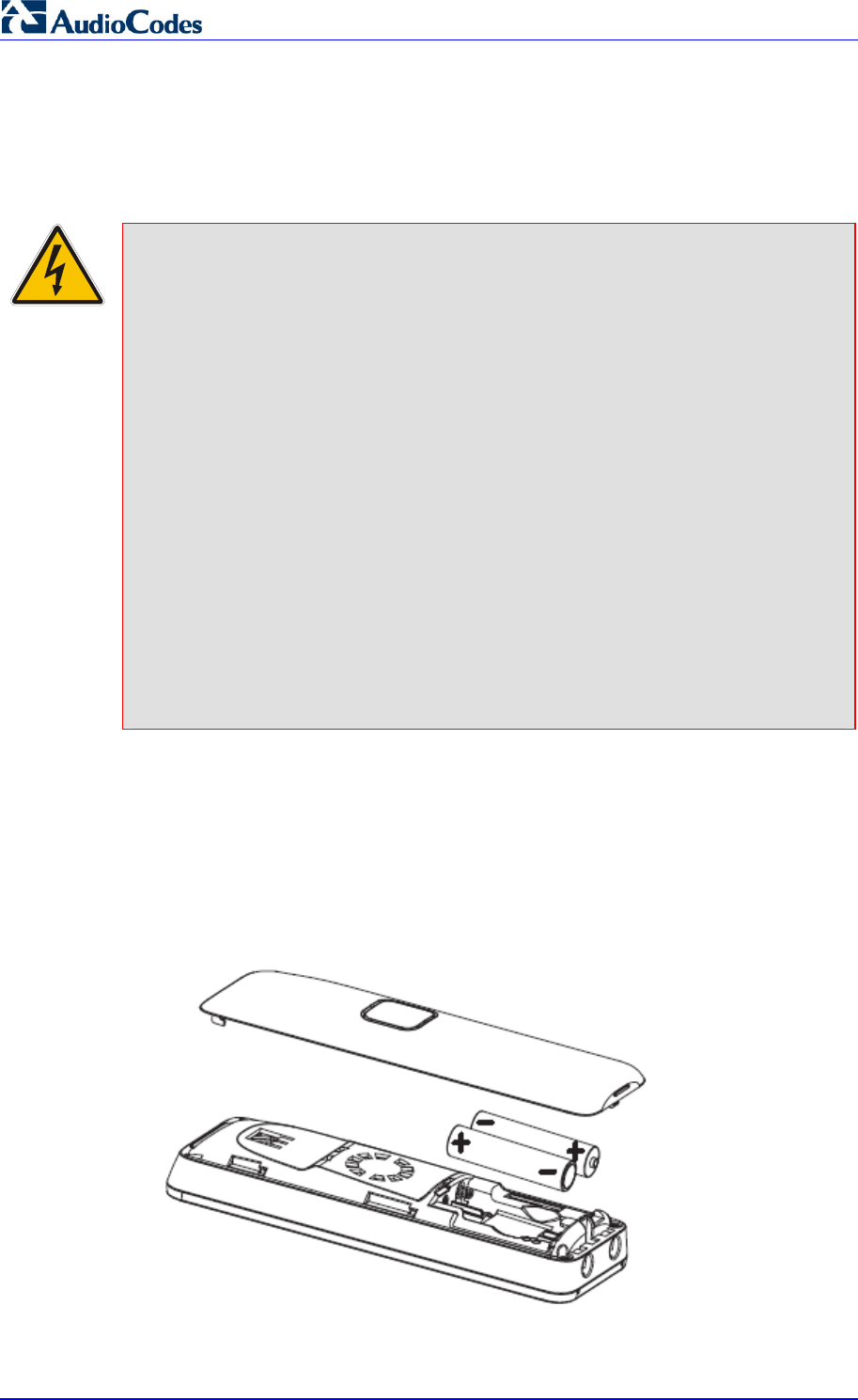
MP252 Multimedia Home Gateway 342 Document #: LTRT-23504
User's Manual
22.2.5 Replacing the Batteries
The handset is shipped with rechargeable batteries. However, if you need to replace them,
follow the procedure described in this section.
Warnings:
• Risk of explosion if battery is replaced by an incorrect battery type; use
only the nickel-metal hydride cell (NiMH) rechargeable batteries as
provided with your phone (for battery specifications, see Section A on
page 389). The manufacturer will not be held liable for damage arising
from such non-compliance.
• Verify correct polarity of the batteries when inserting the batteries.
Incorrect polarity may damage the product.
• The operation periods (as stated in Section A on page 389) for the
handset are only applicable with the default battery capacities.
• Do not use third-party charging bays to charge the batteries.
• Do not immerse batteries in water and do not place in fire.
• Do not mix old and new batteries.
• Do not open or mutilate the batteries. Released electrolyte from the
batteries is corrosive and may cause burns or injury to the eyes or skin.
The electrolyte is toxic and may be harmful if swallowed.
• Do not allow conductive materials such as rings, bracelets, or keys to
touch the batteries, otherwise a short circuit may cause the batteries
and/or the conductive material to overheat and cause burns.
• Avoid touching the battery ends (+, -) or the base unit contacts.
¾ To install the handset batteries:
1. Remove the battery compartment cover, by sliding the cover out from the base of the
phone toward the top end (in the direction of the arrow label printed on the cover). You
can use your thumb to push at the base of the cover.
2. Remove the old batteries (if any) and then place the two batteries (supplied) into the
battery compartment, as indicated.
3. Slide the battery compartment cover back into place.
Figure 22-4: Installing Batteries
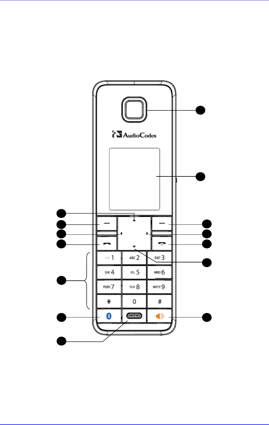
Version 3.4.0 343 June 2011
MP252 Multimedia Home Gateway 22. Getting Started
22.3 Getting to Know Your Phone
22.3.1 Overview of the Handset
The areas of the handset are shown in the figure below and described in the subsequent
table.
Figure 22-5: Areas of the Handset
1
3
2
4
6
5
7
8
9
11
12
13
14
10
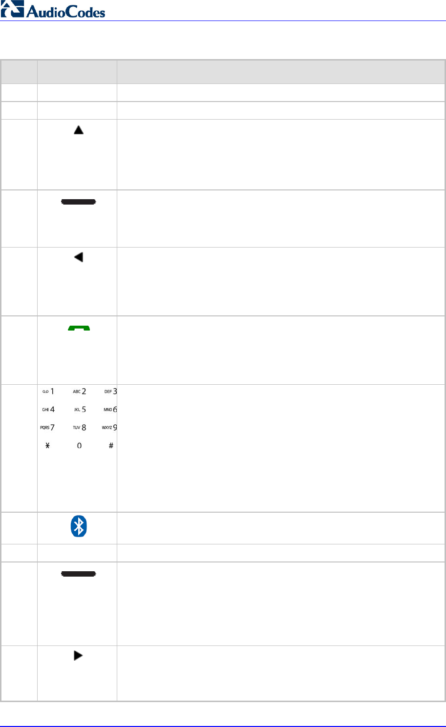
MP252 Multimedia Home Gateway 344 Document #: LTRT-23504
User's Manual
Table 22-1: Handset Description
Item Label Description
1 - Earpiece
2 - Display
3 Up Arrow / Redial List
In idle mode: Press to access the redial list.
In menu mode: Press to scroll up the menu items
In Phonebook list / Redial list / Call List: Press to scroll up the list
During a call: Press to increase the volume
4 Left Softkey
In idle mode: Press to access the main menu
In submenu mode: Press to confirm selection
During a call: Press to access the submenu
5 Left Arrow
In idle mode: Press to list the registered handsets.
In editing/pre-dialing mode: Press to move the cursor one character to
the left.
During a second call: press and hold to conference your calls.
6 Talk On
In idle / pre-dialing mode : Press to make a call
In Redial list / Call List/ Phonebook entry: Press to make a call to the
selected entry in the list
During ringing: Press to answer a call
7
Alphanumeric Keypad, * (Star), # (Hash)
Press to insert a digit / character / * / #
• * key in idle mode: Long press to turn on/off the ringer
• * key in editing mode: Long press to switch the character set
• * key during a call: Short press to switch to tone dialing mode temporaril
y
if using pulse dialing mode currently
• # key in editing mode: Long press to toggle between uppercase or
lowercase character input
• # key in Idle mode: Long press to turn on / off the keypad lock
• 0 key in pre-dialing / number editing mode: Long press to insert a pause
8 Bluetooth
Note: This button will be supported in the next applicable release.
9 - Microphone
10 Right Softkey
In idle mode: Press to access the phonebook
In sub-menu mode: Press to go back to previous level
In editing / pre-dialing mode: Press to clear a character / digit
In editing / pre-dialing mode: Long press to delete all the characters / digit
During a call: Press to hold / unhold the call.
11 Right Arrow
In pre-dialing / editing mode: Press to move the cursor one character to
the right.
During a second call: Press to toggle between calls.

Version 3.4.0 345 June 2011
MP252 Multimedia Home Gateway 22. Getting Started
Item Label Description
12 Talk Off
During a call: Press to end a call and go back to idle screen
When there are two calls and the second is an outgoing call: Press to
transfer the first call to the user of the second call.
In menu / editing mode: Press to go back to idle screen
In Idle: Press and hold to power off the handset
When the handset is power off: Press and hold to power on the handset
13 Down / Call List
In idle mode: Press to access the call list
In menu mode: Press to scroll down the menu items
In Phonebook list / Redial list / Call List: Press to scroll the list
During a call: Press to decrease the volume
14 - Speakerphone
During a call: Press to turn on / off the speakerphone.
Call List / Phonebook entry: Press to make a call with speakerphone
During ringing: Press to answer a call with speakerphone
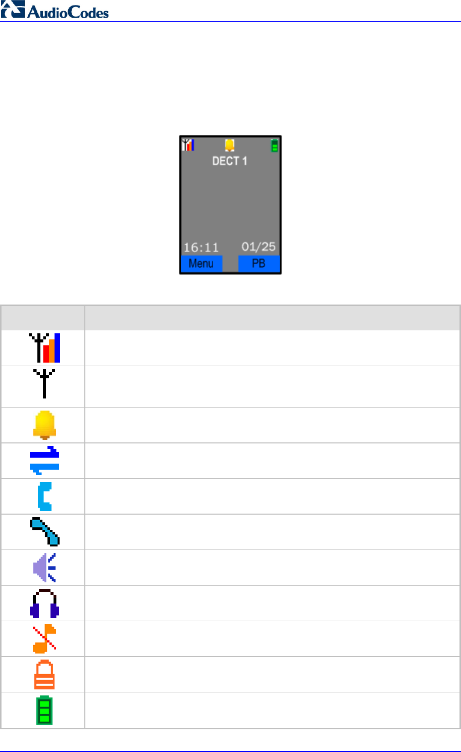
MP252 Multimedia Home Gateway 346 Document #: LTRT-23504
User's Manual
22.3.2 Getting to Know your Handset LCD Screen
The handset LCD provides various icons that are displayed according to the current status
and operational mode of the phone. An example of the phone’s LCD is shown below and the
icons are described in the table below.
Figure 22-6: Areas of the Handset LCD Screen
Table 22-2: Handset LCD Icon Descriptions
Icon Description
Steady when the handset is in range of the base. Additional bars (red, orange, and
blue) are displayed as the signal strength increases.
Flashes when the handset is not registered to the base, in marginal range or out of
range of the base. When the handset is out of range, the LCD displays “Out of
Range” message.
The alarm is set. When the alarm time is reached, this icon flashes. This icon
disappears when the alarm is off.
Intercom is in progress.
Phone is ringing (i.e., incoming call).
Call is in progress.
Hands-free is in use.
Headset is in use.
Ringer is switched off.
keypad is locked.
Handset battery is fully charged.
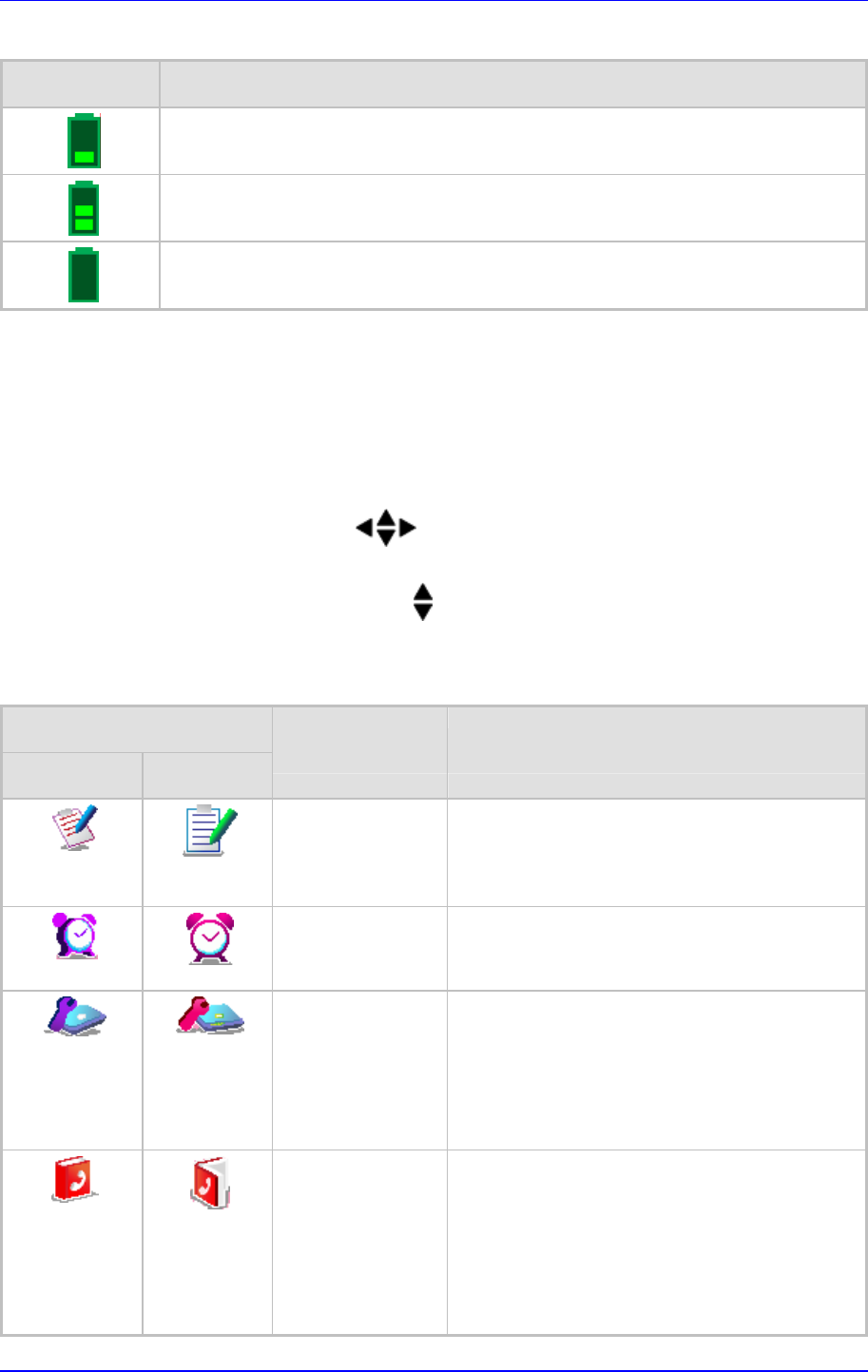
Version 3.4.0 347 June 2011
MP252 Multimedia Home Gateway 22. Getting Started
Icon Description
Handset battery is one-third charged.
Handset battery is two-thirds charged.
Handset battery is empty and needs charging. This icon flashes.
22.3.2.1 Menu Structure
Your phone provides various features and functions that are grouped in the menus.
¾ To access the Menu list and its submenus:
1. Press the Menu softkey.
2. Use the 4-way navigation keys to navigate to the required menu.
3. Press the Select softkey to access the required menu.
4. To drill-down submenus, use the navigation keys to select the required submenu and
then the Select softkey to access it.
Table 22-3: Handset LCD Menus and Submenus
Menu Icon
Unselected Selected Menu Name Submenus
Call List
(See Section 25 on
page 369)
Call List
Missed Calls
Received Calls
Redial List
Clock/Alarm
(see Section 26 on
page 373)
Date & Time
Alarm
Base Settings
(See Section 28 on
page 383)
Manage HS
Line Settings
Modify PIN
BS Default
Product Version
Nemo Mode
Phonebook
(See Section 24 on
page 365)
View
Add
Edit
Delete
Delete All
Note: If the Phonebook is empty, then only the
Add submenu appears.
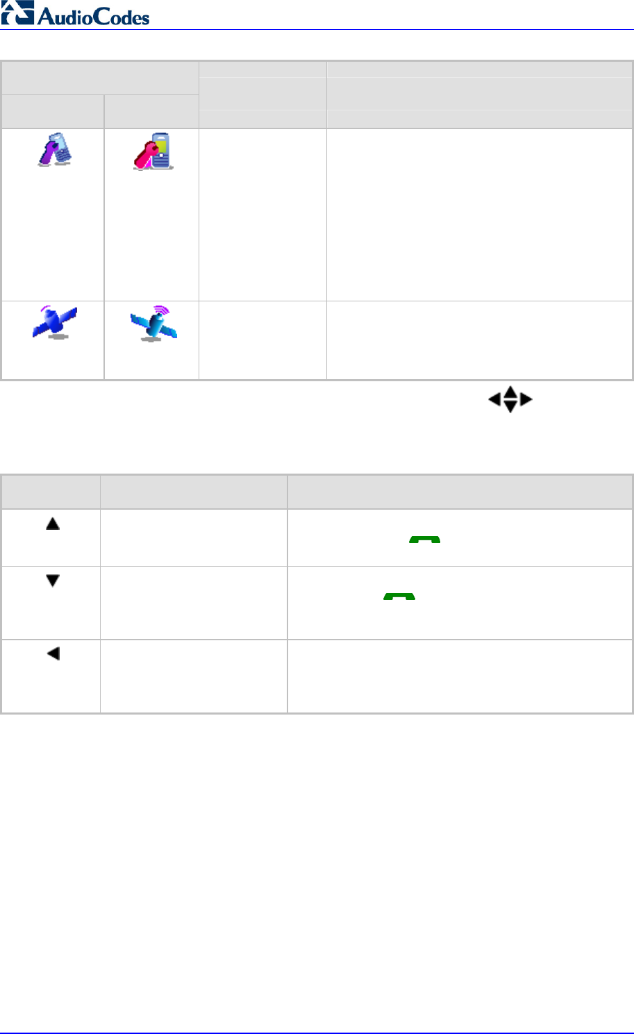
MP252 Multimedia Home Gateway 348 Document #: LTRT-23504
User's Manual
Menu Icon
Unselected Selected Menu Name Submenus
HS Settings
(See Section 27 on
page 377)
Audio Setup
Ring Setup
Tone Setup
Language
Wallpaper
Contrast
Auto Answer
Select Base
HS Default
Registration Base 1
Base 2
Base 3
Base 4
The following menus or submenus can also be accessed using the navigation keys
when the phone is in idle mode:
Table 22-4: Handset LCD Menus and Submenus Accessed using Navigation Keys
Pressed Key Accessed Menu/Submenu Description
Redial List Navigate to the phone number that you want to redial,
and then press the button. For detailed description
on redialing calls, see Section 23.1.5 on page 356.
Call List Navigate to the phone number that you want to dial, and
then press the button. For a detailed description
on dialing from the Call List, see Section 23.1.4 on page
356.
Intercom This submenu allows you to make intercom calls
between handsets. Navigate to the handset that you
want to call. For a detailed description on making
intercom calls, see Section 23.11.1 on page 361.
22.3.2.2 Entering Text and Digits
Your phone allows you to enter strings consisting of letters, digits (numbers) and/or symbols.
These are required, for example, when defining the handset name and adding phonebook
contacts. In addition, your phone supports a variety of character sets including Latin,
Russian, Spanish, and Hebrew.
The character strings are entered using the phone's keypad keys.

Version 3.4.0 349 June 2011
MP252 Multimedia Home Gateway 22. Getting Started
Figure 22-7: Handset Keypad
Each key allows you to enter numerous characters in addition to those printed on the keys
label. The number 1 key provides commonly used characters such as @ and #.
¾ To select a character:
Press the key consecutively until the required character is displayed.
¾ To toggle between upper and lowercase letters:
Press the # key until you hear a beep.
¾ To toggle between character sets (languages):
Press the star key (*) until you hear a beep.
In editing mode, a cursor is displayed to indicate the current text-entry position. It is
positioned at the right of the last character entered.
Writing tips:
Once a character is selected, the cursor moves to the next position after a short pause.
You can move the cursor within the text by using the 4-way navigation keys to
modify the text entry.
Press the Clear softkey to delete the last character.
Press and hold the Clear softkey to delete the entire text string..
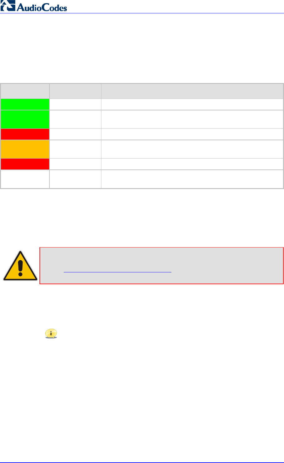
MP252 Multimedia Home Gateway 350 Document #: LTRT-23504
User's Manual
22.3.3 Viewing Base Unit Status with DECT LED
The DECT LED is located on the front panel of MP252 and indicates the operating status of
the cordless phone, as described in the table below:
Table 22-5: DECT LED Description
Color State Description
Green On Base unit is ready to make or receive calls with the handset.
Green Flashing Base is available for handset registration. To register a handset,
see Section 22.4 on page 351
Red On The base unit is on, but no handset is registered to it.
Amber Flashing Handset is being paged. To page (locate) the handset, see
Section 23.10 on page 360.
Red Flash Malfunction in DECT cordless phone.
- Off Phone is switched off. To switch the phone on or off, see Section
22.2.3 on page 342.
22.4 Upgrading MP252 and the Base Unit
If the software version currently running on MP252 is older than Version 3.3.0 build 17, you
need to upgrade your MP252 as well as your MP252 base unit.
Note: If you are a registered customer, you can download the latest MP252 software
file and base unit software file from AudioCodes Web site at
http://www.audiocodes.com/downloads. These files include
V1MOD_SPI_app.bin and MP252_3_3_0_build_17_05_Jan_2011.rmt.
You can view the current software version running on MP252 by using the Web interface, as
follows:
1. Access the MP252 Web interface.
2. From the menu pane, select the Advanced menu, and then click the About MP252
icon; the 'About MP252' screen appears.
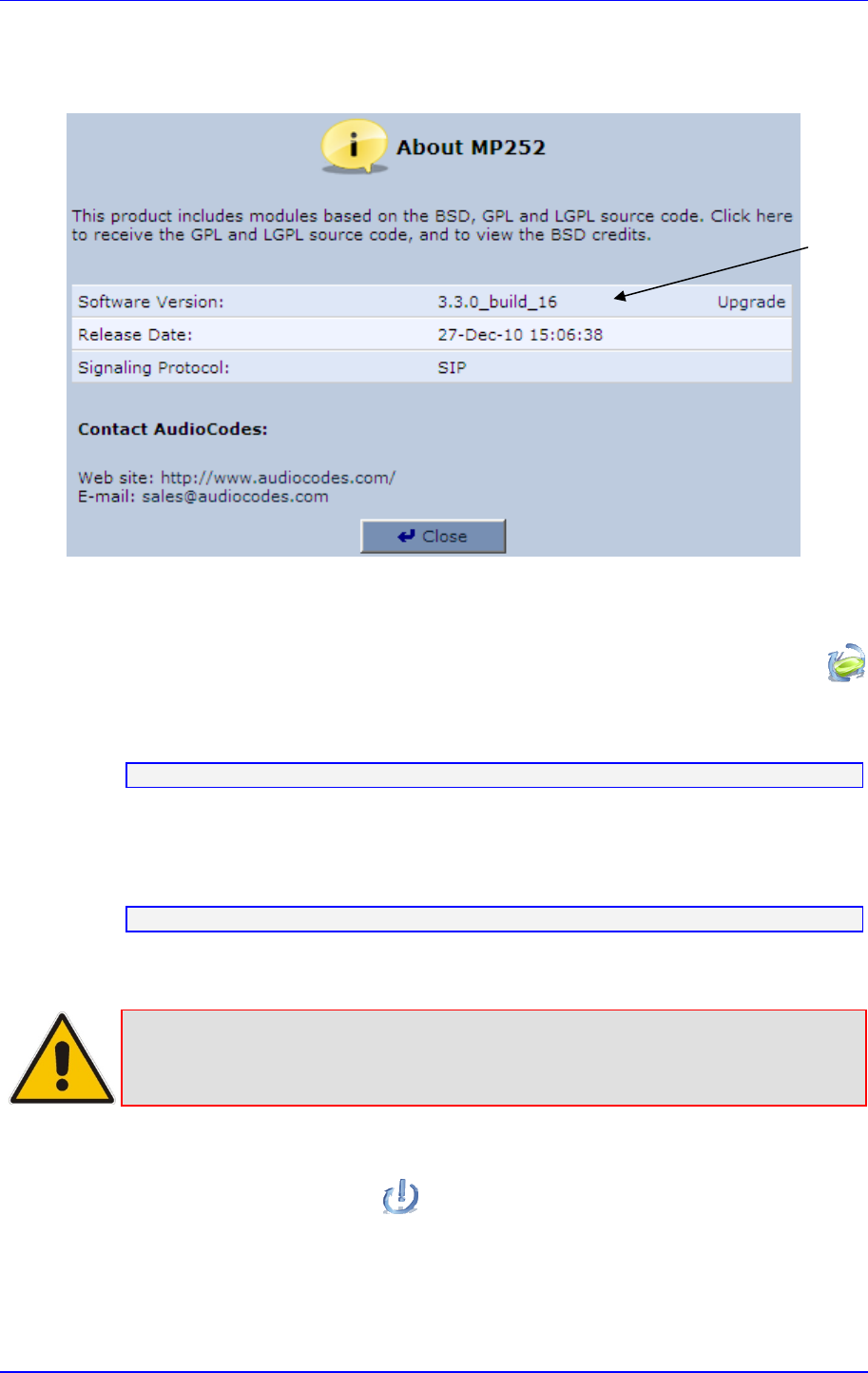
Version 3.4.0 351 June 2011
MP252 Multimedia Home Gateway 22. Getting Started
Table 22-6: About MP252 Screen
¾ To upgrade the MP252 and base unit software versions:
1. Upgrade the MP252 software version to 3.3.0_build_17. This is done in the Web
interface's 'Firmware Upgrade' screen (Advanced menu > Firmware Upgrade
icon). For a detailed description, refer to the MP252 User's Manual.
2. Once upgraded, establish a telnet session with MP252, and then run the following CLI
command:
dect save_settings_in_factory
3. Plug a USB flash drive containing the DECT base version file into the USB port, located
on the rear panel of MP252.
4. Ensure that the DECT LED is lit.
5. Run the following CLI command:
dect upgrade
The upgrade process begins and the DECT LED blinks (fast) green. Upgrade takes
approximately 8 minutes.
Note: During the upgrade process, do NOT power off MP252, remove the USB drive,
nor any other action on MP252.
6. Once the base unit has completed its upgrade (indicated by the DECT LED being lit
steady green again), reboot MP252. This is done in the Web interface's 'Reboot' screen
(Advanced menu > Reboot icon). For a detailed description, refer to the MP252
User's Manual.
Software
Version
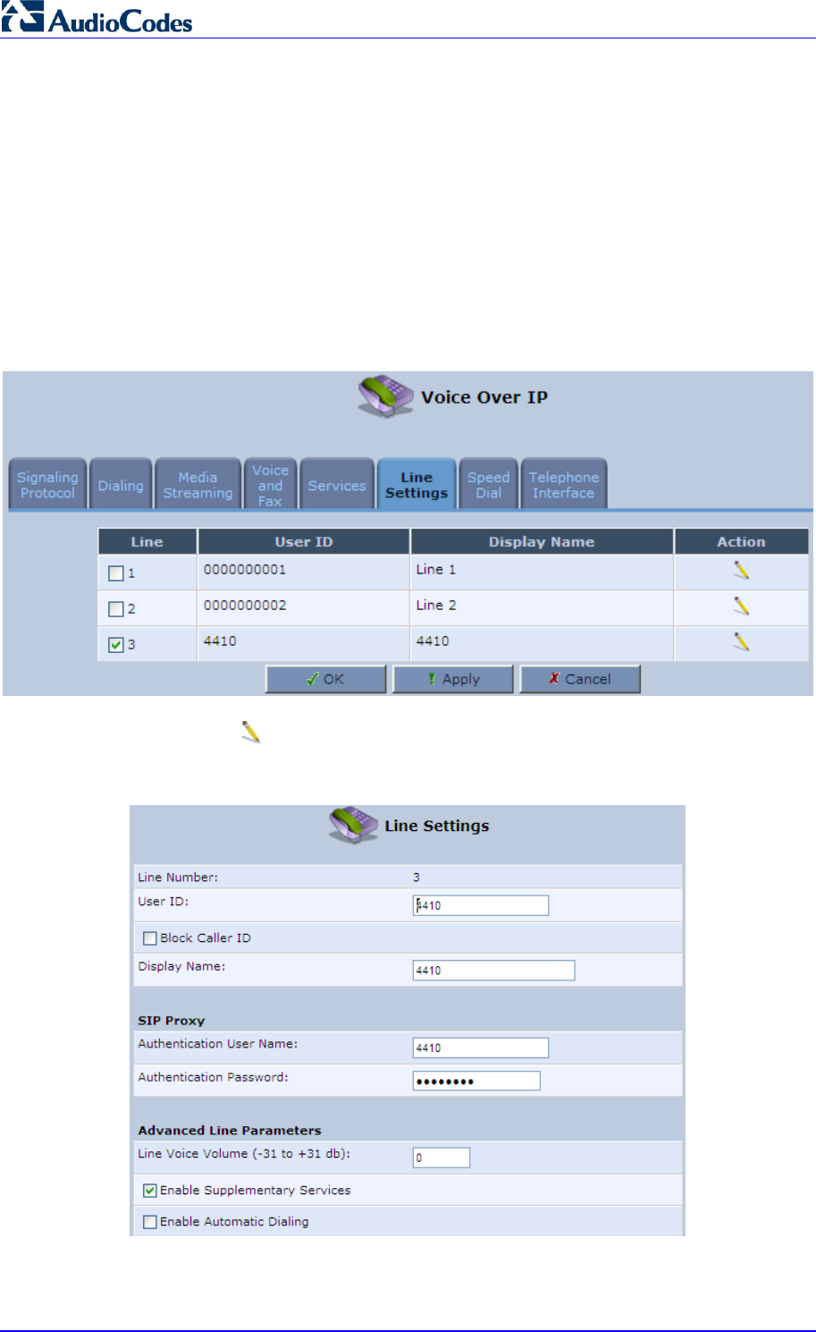
MP252 Multimedia Home Gateway 352 Document #: LTRT-23504
User's Manual
22.5 Defining the MP252 Handset Line
Before you can operate the phone, the handset needs to be defined as one of the MP252
phone lines. By default, the handset is automatically assigned Line 3 of the MP252.
Configuration of this line is done using the MP252 Web interface, as described below.
¾ To define the handset phone line on MP252:
1. Access the MP252 Web interface.
2. From the menu pane, select the Voice Over IP menu; the 'Voice Over IP' screen.
3. Select the Line Settings tab; the 'Line Settings' screen appears.
Table 22-7: Line Settings Screen
4. Click the Edit icon corresponding to Line 3.
Table 22-8: Defining Line 3 Properties
5. Define the following line settings:

Version 3.4.0 353 June 2011
MP252 Multimedia Home Gateway 22. Getting Started
• User ID: phone number (extension) of the MP252 handset
• Display Name: String displayed to remote parties as your caller ID
• Authentication User Name: User name (obtained from your service provider)
used when sending a response to Unauthorized or Proxy Authentication
Requested (401/407)
• Authentication Password: Password (obtained from your service provider) used
when sending a response to Unauthorized or Proxy Authentication Requested
(401/407)
22.6 Registering the Handset to Base Unit
Before you can use your handset, you need to register it to the base unit. Up to five handsets
can be registered to the base unit. If the handset is not registered to the base unit, the
following is displayed on its screen:
icon flashes
“Out of Range” message appears in idle state
¾ To register the handset to the base:
1. Press the Menu softkey.
2. Press the navigation keys to scroll to the Registration icon, and then
press the Select softkey.
3. On the M-252 base unit, press the DECT LED button until (2 – 5 seconds) it starts
flashing green; the base unit enters registration mode. (The registration mode remains
active for 30 seconds, after which the DECT LED stops flashing. Therefore, proceed to
the next step before this interval expires.)
4. Press the navigation keys to choose the base unit (i.e., “Base 1”) to which you want
to register the handset, and then press the Select softkey; the registration process
begins and the “Registering - Waiting” is displayed.
5. When the handset identifies the base, it displays its radio frequency (RF) identification
(each base has a unique RF ID). Click the Accept softkey to confirm (or press the Rej
softkey to cancel registration).
6. On some handsets, you are prompted to enter a PIN code. The default PIN code is 0000
(see Section 28.2 on page 385 for defining the PIN code).
If the handset successfully registers to the base, a confirmation tone is heard and the icon
stops flashing. The handset is automatically allocated the next available handset number.
This handset number is displayed on the handset screen in idle mode. The base unit to which
the handset is successfully registered is marked with an asterisk “*” in the Registration
menu (see Section 27.8 on page 381).
MP252 Multimedia Home Gateway 354 Document #: LTRT-23504
User's Manual
22.7 Checking the Handset Signal Strength
The antenna icon displays the signal strength between your handset and the base unit:
Signal strength is excellent.
Signal strength is good.
Signal strength is poor.
When the icon is steady, the handset is in range of the base (but signal strength
is weak). When the icon flashes, it indicates that the handset is out of range and
there is no link with the base unit.
As the distance between the handset and the base increases, so the signal strength
decreases and vice versa.
Notes:
• The maximum range between the base station and the handset is
approximately 300 meters. Depending on the surrounding conditions as
well as spatial and structural factors, the range may be reduced. The range
indoors is normally less than outdoors.
• If your handset has lost its link with the base unit, you cannot make or
receive calls. In addition, many other phone functions cannot be performed.
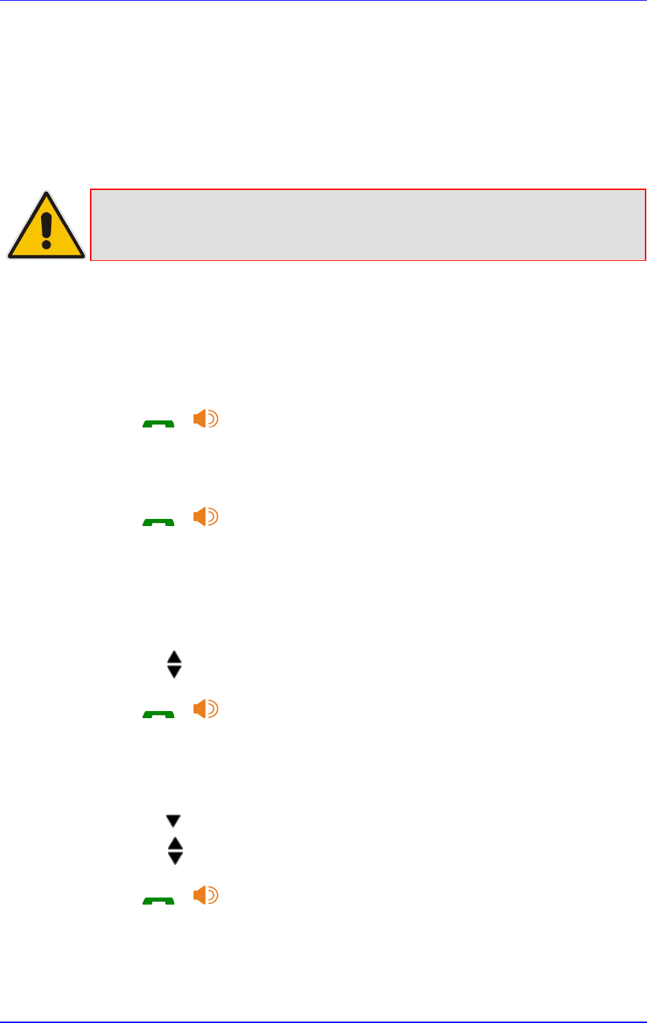
Version 3.4.0 355 June 2011
MP252 Multimedia Home Gateway 23. General Phone Operation
23 General Phone Operation
23.1 Making an External Call
External calls are calls made to remote parties other than another registered headset (if any)
to the MP252 base.
Note: Your handset automatically displays the duration of every call. This is shown in
hours, minutes and seconds format (HH:MM:SS).
23.1.1 Pre-dialing
Preparatory dialing is when you first enter the phone number and only then dial it. This
therefore, allows you to make changes to the number before making the call.
1. Enter the phone number; the number is displayed on the screen. You can make
changes to the number before dialing. Press the Clear softkey to delete digits to the left
of the cursor.
2. Press or to dial the number.
23.1.2 Direct Dialing
Direct dialing is when you activate dialing and only then enter the phone number.
1. Press or to take the line.
2. Enter the phone number; the phone waits a few seconds and then dials the number.
23.1.3 Calling from your Phonebook
If you have added any contacts to your phonebook, you can dial from the phonebook.
1. Press the PB softkey to access the phonebook.
2. Press the navigation keys to choose the desired phonebook entry, and then press
the Select softkey.
3. Press or to dial the selected phonebook entry.
23.1.4 Calling from the Call List
You can dial numbers from previously received or missed calls, which are stored in the Call
List:
1. Press the navigation key to access the Call List.
2. Press the navigation keys to select the desired entry, and then press the Select
softkey.
3. Press or to dial the selected entry.
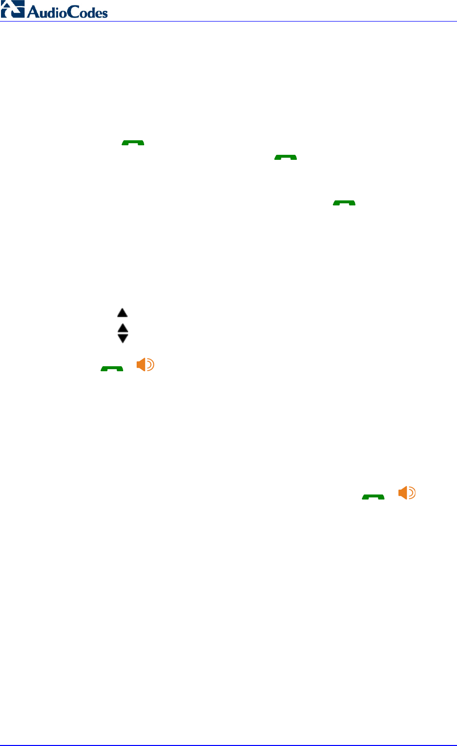
MP252 Multimedia Home Gateway 356 Document #: LTRT-23504
User's Manual
23.1.5 Establishing a Second Call
While you are in an active call, you can establish a second call. When you establish a second
call, the first call is put on hold. You can toggle between the calls by placing one call on hold
while speaking to the other call (see Section 23.11.4 on page 362).
To establish a second call, do one of the following:
Making a second call directly:
1. Press ; the Predialing screen appears.
2. Dial the desired number, and then press again.
Making a second call to a contact in your phonebook:
1. Press the Menu softkey, and then choose Phonebook.
2. Select a number from the phonebook, and then press .
Manually placing the first call on hold before making a second call:
1. Press the Hold softkey to place the current call on hold.
2. Establish a second call by doing one of the previously mentioned methods.
23.1.6 Redialing a Number
You can dial numbers that were previously dialed, which are stored in the Redial List.
1. Press the navigation key to access the Redial List.
2. Press the navigation keys to select the desired number, and then press the Select
softkey.
3. Press or to dial the selected entry.
23.2 Answering a Call
When you receive a call, your phone rings and the following is displayed on your screen:
“Incoming Call”
Calling number is displayed
¾ To answer a call:
If the handset is not on the base: When the phone rings, press or .
If the handset is on the base and when Auto Answer is set to On: When the phone
rings, pick up the handset.

Version 3.4.0 357 June 2011
MP252 Multimedia Home Gateway 23. General Phone Operation
23.3 Answering or Rejecting a Second Call
While you are talking on the phone, you can receive a second call. The phone provides the
following indications of a second incoming call:
A beep tone is sounded.
The “Call Waiting” message is displayed on the screen with the details (name and
number) of the calling party.
¾ To answer a second call:
Press to answer the call; the call with the second call party is established and the
first call is put on hold.
¾ To reject a second call:
Press to reject the second call.
Once you have answered the second call, you can toggle between the calls by placing one
call on hold and speaking to the other call (see Section 23.11.4 on page 362).
23.4 Ending a Call
To end call, you can do one of the following:
Press .
Place the handset on the charger.
When you end the call, the screen displays “Released”.
23.5 Adjusting Earpiece and Speakerphone Volume
during a Call
During a call, you can adjust the volume of the handset earpiece and hands-free. There are
five volume levels provided on the handset. This is done during an ongoing call.
¾ To adjust the earpiece and hands-free volume:
During a call, press the up / down navigation keys to increase or decrease the
volume level respectively. The screen displays the current volume setting.
Notes:
• When you end the call, the selected volume applies to all future calls, until it
is modified again.
• To adjust the earpiece and speaker volume when the phone is in idle state,
see Section 27.1 on page 377.
23.6 Muting a Call
You can talk to someone nearby without letting the caller hear you during a call. This is done
by muting the microphone of the handset.
¾ To mute and un-mute a call:
1. To mute the call:
a. During a call, press the Menu softkey.
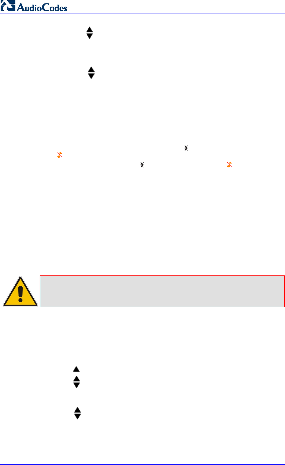
MP252 Multimedia Home Gateway 358 Document #: LTRT-23504
User's Manual
b. Press the navigation keys to select the Mute option, and then press the Select
softkey; the microphone is muted and “Call Muted” is displayed on the screen.
2. To un-mute the call:
a. Press the Menu softkey.
b. Press the navigation keys to select the Unmute option, and then press the
Select softkey; the microphone is un-muted and you can now converse with the
caller.
23.7 Turning Off the Ringer
You can turn off the ringer of the handset for audibly notifying of incoming calls.
¾ To turn off and on the ringer:
1. To turn off the ringer: In idle mode, press and hold (asterisk) key to turn off the ringer.
The icon is displayed on the screen.
2. In silent mode, press and hold the key to turn on the ringer. The icon disappears.
23.8 Redial List
The Redial List stores up to 100 of the last numbers that you have called. If the number that
you called also appears in the phonebook, then the contact name is displayed in the list,
instead of the number.
The Redial List allows you to do the following:
Redial a listed number (see Section 23.1.5)
Add a listed number to the phonebook
Delete a listed number
Delete all entries in the Redial List
Note: If there are no numbers in the Redial List, the screen displays “List Empty”.
23.8.1 Saving a Redial Number to the Phonebook
You can save a number listed in the Redial List to the phonebook.
¾ To save a listed number to the phonebook:
1. Press the navigation key to access the Redial List.
2. Press the navigation keys to select the desired number, and then press the Select
softkey.
3. Press the Menu softkey.
4. Press the navigation keys to choose the Add to PB option, and then press the
Select softkey; the phonebook is accessed with the number already appearing in the
Number field.
5. Enter the details (i.e., name) of the contact in the phonebook. For a detailed description
of adding contacts to the phonebook, see Section 24.1.

Version 3.4.0 359 June 2011
MP252 Multimedia Home Gateway 23. General Phone Operation
23.8.2 Deleting a Number from the Redial List
You can delete a number from the Redial List.
¾ To delete an entry in the Redial List:
1. Press the navigation key to access the Redial List.
2. Press the navigation keys to select the desired number, and then press the Select
softkey.
3. Press the Menu softkey.
4. Press the navigation keys to choose the Delete option, and then press the Select
softkey; the “Delete Confirm” message is displayed.
5. Press the OK softkey to confirm deletion.
23.8.3 Deleting the Entire Redial List
You can delete all the entries in the Redial List.
¾ To delete all entries in the Redial List:
1. Press the navigation key to access the Redial List.
2. Press the Select softkey
3. Press the Menu softkey.
4. Press the navigation keys to choose the Delete All option, and then press the Select
softkey; the “Delete Confirm” message is displayed.
5. Press the OK softkey to confirm deletion.
23.9 Locking the Keypad
You can lock the keypad to prevent accidental presses on the handset while carrying it
around. This can be done only when the handset is in idle mode.
¾ To lock the keypad:
1. To lock the keypad: In idle mode, press and hold the # key; the icon is displayed.
2. To unlock the keypad: In idle mode, press and hold the # key, the icon disappears.
Note: You are unable to make any calls when the keypad is locked.
23.10 Paging the Handset
You can locate the handset by paging the handset from the base.
¾ To page a handset:
On the base unit, press the DECT button until the LED changes to orange; all handsets
registered to the base ring up to 60 seconds and “Incoming Call – HS Locator” is

MP252 Multimedia Home Gateway 360 Document #: LTRT-23504
User's Manual
displayed on the LCD. You can stop the paging by pressing any key on the handset
except the Silent softkey.
Version 3.4.0 361 June 2011
MP252 Multimedia Home Gateway 23. General Phone Operation
23.11 Call Handling for Multiple, Registered Handsets
The MP252 supports multiple, registered handsets. This section describes call handling
between multiple registered handsets. This includes how to make internal calls, transfer
external calls from one handset to another handset, and make conference calls.
23.11.1 Calling (Intercom) Another Handset
An intercom call is a call from one handset to another handset that is also registered to the
MP252 base unit.
Note: An intercom call can only involve two handsets that share the same base unit.
¾ To call (intercom) another handset:
1. Press the navigation key; the screen displays a list of the registered handsets.
2. Press the navigation keys to select the handset to which you want to make a call.
3. Press the Select softkey; the called handset rings.
4. On the called handset, press to establish the internal call.
23.11.2 Transferring an External Call to Another Handset
You can transfer an external call (i.e., not a call from another handset) received on one
handset, to another handset.
23.11.2.1 Announced Call Transfer
An announced call transfer is when you can speak to the handset to where you want to
transfer the external call before transferring the call.
¾ To make an announced call transfer:
1. During the call with the external call, press the navigation key; the screen displays a
list of the registered handsets.
2. Press the navigation keys to select the handset to where you want to transfer the call.
3. Press the Select softkey; the external call is automatically put on hold and the called
handset rings.
4. On the called handset, press or to establish an internal call between the
handsets.
5. On the calling handset, press the Menu softkey, and then choose the Transfer option;
the external call is transferred to the called handset and the current call with the calling
handset is terminated.
23.11.2.2 Unannounced Call Transfer
An unannounced call transfer is when you transfer the external call to a handset without
speaking to the handset to where the call is transferred.

MP252 Multimedia Home Gateway 362 Document #: LTRT-23504
User's Manual
¾ To make an unannounced call transfer:
1. During the call with the external call, press the navigation key; the screen displays a
list of the registered handsets.
2. Press the navigation keys to select the handset to where you want to transfer the call.
3. Press the Select softkey; the external call is automatically put on hold and the called
handset rings.
4. On the calling handset, press the Menu softkey, and then choose the Transfer option;
the external call is transferred to the called handset and the current call with the calling
handset is terminated.
5. On the called handset, press or to receive the transferred call.
23.11.3 Transferring an External Call to Another External Call
If you have two external calls, one an active call and the other a waiting call (or call on hold),
you can transfer the active call to the waiting call party.
¾ To transfer an external call to a remote party:
1. Press the Menu softkey, and then select the Transfer option
2. Press the OK softkey to confirm the transfer; the two external call parties are connected,
and you are disconnected from the calls.
23.11.4 Toggling between External and Internal Calls
If you have established an external call, you can establish another call (i.e., internal or
external) and then toggle between these calls. When one call is active, the other call is on
hold.
¾ To toggle between calls:
Press the navigation key; the currently active call is put on hold and the currently held
party is now active.
Version 3.4.0 363 June 2011
MP252 Multimedia Home Gateway 23. General Phone Operation
23.11.5 Three-Way Conference Calls
You can create three-way conference calls composed of the following call party types:
Two handsets and an external party
Your handset and two external calls
23.11.5.1 Making a Three-Way Conference Call with Another Handset and an
External Party
The conference call feature allows one external call to be shared with two handsets (in
intercom). The three parties can share the conversation and no network subscription is
required.
¾ To make a three-way conference with another handset and an external
call:
1. During the call with the external call, press the navigation key; the screen displays a
list of the registered handsets.
2. Press the navigation keys to select the handset with which you want to establish a
three-way conference call.
3. Press the Select softkey; the external call is automatically put on hold and the called
handset rings.
4. On the called handset, press or to establish the internal call.
5. On the calling handset, press and hold the navigation key for 3 seconds to establish
the 3-way conference call.
Note: If any handset hangs up during the conference call, the other handset still
remains connected with the external call.

MP252 Multimedia Home Gateway 364 Document #: LTRT-23504
User's Manual
23.11.5.2 Making a Three-Way Conference Call with your Handset and two
External Calls
You can make a three-way conference call between your handset and two external calls.
This can be done when you have two external calls, where you are talking with one and the
other call is waiting (on hold).
¾ To make a three-way conference with two external calls:
1. Press the Menu softkey, and then choose the Conference option.
2. Press the OK softkey to confirm the conference; the two external calls parties are
included in your conference call.
Version 3.4.0 365 June 2011
MP252 Multimedia Home Gateway 24. Phonebook
24 Phonebook
Your handset can store up to 150 phonebook contacts. Each phonebook contact can have a
name of up to 12 characters long and a phone number of up to 24 digits.
24.1 Adding a New Contact
Follow the procedure below for adding a new contact to your phonebook.
¾ To add a new contact to a phonebook:
1. In idle state, press the Menu softkey.
2. Press the navigation keys to scroll to the Phonebook icon.
3. Press the Select softkey to access the Phonebook.
4. Press the navigation keys to choose the Add option, and then press the Select
softkey.
5. Enter the contact details, using the navigation keys to move from one field to the
next:
• F. Name: first name
• Name: family name
• Number: phone number
Note: The name and phone number are mandatory fields.
6. Press the OK softkey to save the phonebook entry.
Note: The phonebook displays the contacts in alphabetical order.

MP252 Multimedia Home Gateway 366 Document #: LTRT-23504
User's Manual
24.2 Editing a Contact
You can edit contacts listed in your phonebook.
¾ To edit a phonebook contact:
1. In idle state, press the Menu softkey.
2. Press the navigation keys to scroll to the Phonebook icon.
3. Press the Select softkey to access the Phonebook.
4. Press the navigation keys to choose the Edit option, and then press the Select
softkey.
5. Press the navigation keys to choose the contact that you want to edit, and then press
the Select softkey; the contact’s details are displayed.
6. Press the Select softkey to edit the contact’s details.
7. Press the navigation keys to move between fields, and then edit the fields as
required.
8. When you have completed your modification, ensure that you are in the melody field,
and then press the OK softkey; the “Saved” message is displayed.
24.3 Viewing Contacts
You can view a list of all contacts in your phonebook.
¾ To view all contacts in your phonebook:
1. In idle state, press the PB softkey; the phonebook opens, displaying a list of the
contacts.
2. Search a contact, by performing one of the following:
• Navigation keys: Scroll through the list of contacts using the navigation keys.
• Search feature: Using the keypad, enter the name of the contact. As you enter
letters, the phonebook locates contacts that match the entered letters. For
example, if you want to search for the contact “Sue”, as you press the key for the es
letter (“s”), the phonebook locates contacts whose names begin with this string. As
you enter the next letter (i.e., “u”), so the contacts whose names begin with “su”
appear, and so on.
3. To view the details of a contact, press the navigation keys to select the contact, and
then press the Select softkey.
You can also view the list of phonebook contacts from the Menu list:
4. In idle state, press the Menu softkey.
5. Press the navigation keys to scroll to the Phonebook icon.
6. Press the Select softkey to access the Phonebook.
7. Press the navigation keys to choose the View option, and then press the Select
softkey.
8. Follow steps 2 through 3 of the procedure above.

Version 3.4.0 367 June 2011
MP252 Multimedia Home Gateway 24. Phonebook
24.4 Deleting a Contact
You can delete a selected contact in the phonebook.
¾ To delete a contact in the phonebook:
1. In idle state, press the Menu softkey.
2. Press the navigation keys to scroll to the Phonebook icon.
3. Press the Select softkey to access the Phonebook.
4. Press the navigation keys to choose the Delete option, and then press the Select
softkey.
5. Press the navigation keys to choose the contact that you want to delete, and then
press the Select softkey; the contact’s details are displayed.
6. Press the Select softkey; the “Delete Confirm” message is displayed.
7. Press the OK softkey to confirm deletion (or the Back softkey to cancel); the contact is
removed from the phonebook.

MP252 Multimedia Home Gateway 368 Document #: LTRT-23504
User's Manual
24.5 Deleting All Contacts
You can delete all contacts from the phonebook.
¾ To delete all contacts from the phonebook:
1. In idle state, press the Menu softkey.
2. Press the navigation keys to scroll to the Phonebook icon.
3. Press the Select softkey to access the Phonebook.
4. Press the navigation keys to choose the Delete All option, and then press the Select
softkey; the “Delete Confirm” message is displayed
5. Press the OK softkey to confirm deletion (or the Back softkey to cancel); all contacts are
removed from the phonebook.

Version 3.4.0 369 June 2011
MP252 Multimedia Home Gateway 25. Call List
25 Call List
If you have subscribed to a Caller Line Identification (also referred to as Caller ID) service
with your network service provider, then when your phone rings for an incoming call, the
phone displays the calling number (and the associated name of the caller if listed in your
phonebook). If the caller’s number is withheld, “Withheld” is displayed. If the caller’s number
is unavailable, “Out Of Area” is displayed.
The phone's Call List stores up to 100 answered and unanswered (missed) calls, displaying
the date and time of the calls.
25.1 Viewing the Call List
All unanswered (missed) and answered (received) calls are saved in the Call List with the
latest call displayed at the top of the list. When the Call List is full, the oldest call is replaced
by a new call.
Missed calls are marked with an asterisk (*) at the beginning of the missed call entry. Once
the missed call has been read, the * is removed.
You can view the Call List by performing one of the following:
In the idle state, press the navigation key.
or
Using the Menu:
1. In idle state, press the Menu softkey.
2. Press the navigation keys to scroll to the Call List icon, and then
press the Select softkey to access the Call List.
3. Press the navigation keys to choose one of the following options:
♦ Call List: displays recently answered and missed calls
♦ Missed Calls: displays only unanswered calls
♦ Received Calls: displays only answered calls
♦ Redial List: displays calls that were previously dialed
4. Press the Select softkey to access the selected option; the call details–call
duration and date and time of the call–are displayed.

MP252 Multimedia Home Gateway 370 Document #: LTRT-23504
User's Manual
25.2 Saving a Call List Number to the Phonebook
You can save a number in the Call List to your phonebook.
¾ To save a Call List entry to the phonebook:
1. In idle state, press the Menu softkey.
2. Press the navigation keys to scroll to the Call List icon.
3. Press the Select softkey to access the Call List.
4. Press the navigation keys to choose the required Call List option (see previous
Section)
5. Press the navigation keys to choose the entry that you want to add to the phonebook,
and then press the Select softkey.
6. Press the Menu softkey.
7. Press the navigation keys to choose the Add to PB option, and then press the
Select softkey; the phonebook is accessed, prompting you to enter the contact’s details
(the phone number as appearing in the Call List is automatically entered in the
phonebooks Number field). For a description on adding contacts to the phonebook, see
Section 24.1 on page 365.
25.3 Dialing a Call List Number
You can dial a number listed in the Call List.
¾ To dial a number listed in the Call List:
1. Access the Call List menu (see Section 25.1 on page 369).
2. Press the navigation keys to choose the required Call List option (e.g., Missed Calls),
and then press the Select softkey.
3. Press the navigation keys to choose the entry that you want to dial, and then press
the Select softkey.
4. Press to dial the number.

Version 3.4.0 371 June 2011
MP252 Multimedia Home Gateway 25. Call List
25.4 Deleting a Call List Number
You can delete an entry in the Call List.
¾ To delete a number in the Call List:
1. Access the Call List menu (see Section 25.1 on page 369).
2. Press the navigation keys to choose the required Call List option (e.g., Missed Calls),
and then press the Select softkey.
3. Press the navigation keys to choose the entry that you want to delete, and then press
the Select softkey.
4. Press the Menu softkey.
5. Press the navigation keys to choose the Delete option, and then press the Select
softkey; the “Delete Confirm” message is displayed
6. Press the OK softkey to confirm deletion (or the Back softkey to cancel); the entry is
removed from the Call List.

MP252 Multimedia Home Gateway 372 Document #: LTRT-23504
User's Manual
25.5 Deleting the Entire Call List
You can delete all entries listed in the Call List. When you delete all entries, all entries in the
Call List, Missed Calls, Received Calls, and Redial List groups are deleted. If you access the
Call List after deleting all entries, the “List Empty” message is displayed.
¾ To delete a number in the Call List:
1. Access the Call List menu (see Section 25.1 on page 369).
2. Press the navigation keys to choose the required Call List option (e.g., Missed Calls),
and then press the Select softkey.
3. Press the Select softkey once again.
4. Press the Menu softkey.
5. Press the navigation keys to choose the Delete All option, and then press the Select
softkey; the “Delete Confirm” message is displayed
6. Press the OK softkey to confirm deletion (or the Back softkey to cancel); all entries are
removed from the Call List.

Version 3.4.0 373 June 2011
MP252 Multimedia Home Gateway 26. Clock and Alarm
26 Clock and Alarm
You can set the phone’s date and time as well as set an alarm.
26.1 Date and Time
You can set the phone’s date and time as well as determine the format of the date and time.
26.1.1 Changing the Date Format
You can change the date format. This can be either DD-MM-YYYY (for example,
25-12-2011) or MM-DD-YYYY (for example, 12-25-2011).
¾ To change the date format:
1. In idle state, press the Menu softkey.
2. Press the navigation keys to scroll to the Clock/Alarm icon, and then
press the Select softkey to access the menu.
3. Press the navigation keys to choose the Date & Time option, and then press the
Select softkey.
4. Press the navigation keys to choose the Date Format option, and then press the
Select softkey.
5. Press the navigation keys to choose the desired format, and then press the Select
softkey; the new date format is applied and the “Saved” message is displayed.
26.1.2 Changing the Time Format
You can change the time format. This can be either 12-hour format (for example, 5:30 PM) or
24-hour format (for example, 17:30).
¾ To change the time format:
1. In idle state, press the Menu softkey.
2. Press the navigation keys to scroll to the Clock/Alarm icon, and then
press the Select softkey to access the menu.
3. Press the navigation keys to choose the Date & Time option, and then press the
Select softkey.
4. Press the navigation keys to choose the Time Format option, and then press the
Select softkey.
5. Press the navigation keys to choose the desired format, and then press the Select
softkey; the new time format is applied and the “Saved” message is displayed.
26.1.3 Setting the Time and Date
You can set the current time and date.
MP252 Multimedia Home Gateway 374 Document #: LTRT-23504
User's Manual
¾ To set the time and date:
1. In idle state, press the Menu softkey.
2. Press the navigation keys to scroll to the Clock/Alarm icon, and then
press the Select softkey to access the menu.
3. Press the navigation keys to choose the Set Date/Time option, and then press the
Select softkey.
4. Press the navigation keys to access the time or date area.
5. To set the time:
• To move between hours, minutes and AM/PM (depending on format), use the
navigation keys.
• If the selected format is 12 hours (see Section 26.1.2 on page 373), then to select
AM or PM, use the navigation keys.
6. To set the date, use the navigation keys to move between day, month and year.
Set the date according to the format that you selected in Section 26.1.2 on page 373.
Note: If you enter an invalid value, an error tone is emitted and the cursor flashes on
the incorrect entry.
7. Press the OK softkey to save the new date and time.
26.2 Alarm
Your phone provides a built-in alarm clock. You can select the melody to play when the alarm
time is reached. You can also activate the snooze time so that when the alarm rings, you can
stop it temporarily and the alarm will sound again at the end of the snooze period (i.e., two
minutes).
When an alarm is set, the alarm icon appears on the screen. When the alarm time is
reached, the alarm and Alarm/Clock icons flash on the screen, and the alarm
melody plays for 45 seconds.
Notes:
• When the alarm sounds, you can stop it or snooze it even if the handset
keypad is locked (described in Section 23.9 on page 360).
• The alarm volume level is the same as the settings of the handset ringer
volume (see Section 23.5 on page 358). If the handset ringer is set to
Volume Off, the alarm still sounds at Volume 1 level.
• During an external or internal call, if an alarm is set and the alarm time is
reached, the alarm icon and “Alarm On” flashes on the screen and the
current call display details (i.e., call duration etc.) disappear. Once you
press any key to activate the snooze or press the Off softkey to disable the
alarm, the current call details is displayed again on the screen.
• If the phone rings for an incoming call and the alarm time is reached, the
alarm does not sound. However, if the snooze alarm is enabled, the alarm
sounds again at the end of the snooze period provided that the phone is not
ringing or in paging mode at the end of the snooze period.

Version 3.4.0 375 June 2011
MP252 Multimedia Home Gateway 26. Clock and Alarm
26.2.1 Setting the Alarm
The alarm time is set as described below. When the alarm is set, the alarm icon is
displayed on the main screen.
¾ To set the alarm:
1. In idle state, press the Menu softkey.
2. Press the navigation keys to scroll to the Clock/Alarm icon, and then
press the Select softkey to access the menu.
3. Press the navigation keys to choose the Alarm option, and then press the Select
softkey.
4. Press the navigation keys to choose the Alarm On option, and then press the Select
softkey.
5. Press the navigation keys to move between hours, minutes, and AM/PM. If the
time format is 12 hours (see Section 26.1.2 on page 373), then to select AM or PM, use
the navigation keys.
6. Press the OK softkey.
7. Press the navigation keys to choose whether you want the snooze functionality
(Snooze On), and then press the Select softkey; the alarm time is saved and the alarm
icon is displayed on the main screen.

MP252 Multimedia Home Gateway 376 Document #: LTRT-23504
User's Manual
26.2.2 Defining the Alarm Melody
You can define the melody that is played when the alarm sounds.
¾ To set the alarm melody:
1. In idle state, press the Menu softkey.
2. Press the navigation keys to scroll to the Clock/Alarm icon, and then
press the Select softkey to access the menu.
3. Press the navigation keys to choose the Alarm option, and then press the Select
softkey.
4. Press the navigation keys to choose the Alarm Melody option, and then press the
Select softkey; a list of melodies is displayed.
5. Press the navigation keys to choose the required melody (a sample of the melody is
played when you highlight a melody), and then press the Select softkey; the melody is
applied to the alarm and the “Saved” message is displayed.
26.2.3 Disabling the Alarm
You can set the alarm to off so that it does not ring at all.
¾ To set the alarm to off:
1. In idle state, press the Menu softkey.
2. Press the navigation keys to scroll to the Clock/Alarm icon, and then
press the Select softkey to access the menu.
3. Press the navigation keys to choose the Alarm option, and then press the Select
softkey.
4. Press the navigation keys to choose the Alarm Off option, and then press the Select
softkey.
26.2.4 Switching Off or Snoozing the Alarm
When the alarm rings, you can either switch it off entirely or you can snooze the alarm so that
it switches off temporarily and then rings again after two minutes.
To switch off the alarm when it rings, press the Off softkey or key; the alarm
icon disappears from the main screen.
To activate the snooze alarm when it rings, press the Snooze softkey or any other key
except the Off softkey or key; the alarm icon remains displayed in the main
screen.
Version 3.4.0 377 June 2011
MP252 Multimedia Home Gateway 27. Customizing the Handset
27 Customizing the Handset
Your phone comes with a selection of settings that you can change to personalize your
handset.
27.1 Adjusting Speaker and Earpiece Volume
You can adjust the speaker volume as well as the earpiece volume. The phone supports five
volume levels from which you can choose.
¾ To adjust the volume:
1. In idle state, press the Menu softkey.
2. Press the navigation keys to scroll to the HS Settings icon, and then
press the Select softkey.
3. Press the navigation keys to choose the Audio Setup option, and then press the
Select softkey.
4. Press the navigation keys to choose the Speaker Volume or Ear Volume option to
adjust the speaker or earpiece volume respectively, and then press the Select softkey.
5. Press the navigation keys to select the volume level.
6. Press the OK softkey; the volume level is saved.
Note: You can also adjust the volume during a call, as described in Section 23.5 on
page 358.

MP252 Multimedia Home Gateway 378 Document #: LTRT-23504
User's Manual
27.2 Ring Settings
27.2.1 Choosing the Internal Ringer Melody
You can select the ringer melody that is played when an incoming call is received from
another handset registered to the MP252 base.
¾ To select the internal ringer melody:
1. In idle state, press the Menu softkey.
2. Press the navigation keys to scroll to the HS Settings icon, and then
press the Select softkey.
3. Press the navigation keys to choose the Ring Setup option, and then press the
Select softkey.
4. Press the navigation keys to choose the Internal Ringer option (a sample of the
melody is played when browsing the list), and then press the Select softkey; a list of
melodies is displayed.
5. Press the navigation keys to choose the desired melody, and then press the Select
softkey; the melody is saved.
27.2.2 Choosing the External Ringer Melody
You can select the ringer melody that is played when an incoming call is received from an
external party.
¾ To select the external ringer melody:
1. In idle state, press the Menu softkey.
2. Press the navigation keys to scroll to the HS Settings icon, and then
press the Select softkey.
3. Press the navigation keys to choose the Ring Setup option, and then press the
Select softkey.
4. Press the navigation keys to choose the External Ringer option (a sample of the
melody is played when browsing the list), and then press the Select softkey; a list of
melodies is displayed.
5. Press the navigation keys to choose the desired melody, and then press the Select
softkey; the melody is saved.

Version 3.4.0 379 June 2011
MP252 Multimedia Home Gateway 27. Customizing the Handset
27.2.3 Adjusting the Ringer Volume
You can adjust the handset’s ringer volume.
¾ To adjust the ringer volume:
1. In idle state, press the Menu softkey.
2. Press the navigation keys to scroll to the HS Settings icon, and then
press the Select softkey.
3. Press the navigation keys to choose the Ring Setup option, and then press the
Select softkey.
4. Press the navigation keys to choose the Ring Volume option, and then press the
Select softkey; a volume bar is displayed indicating the volume level.
5. To increase the volume, press the or navigation keys; to decrease the volume,
press the or navigation keys. Levels filled in with color indicate the selected
volume level. The respective volume level is played during your selection.
6. To silence the ringer, press the or navigation keys until “Volume Off” is displayed.
when the ringer is off, the icon is displayed on the main screen.
7. Press the OK softkey to save your settings.
27.3 Alert Tones
27.3.1 Setting the Key Tone
A single beep is emitted when you press a key on the handset. You can set whether only a
beep is emitted upon any key pressed or only Dual Tone Multi Frequencies (DTMF) tones
are emitted (when numbers 0-9 and symbols * and # are pressed), or both. You can also turn
off the key tone.
¾ To set the key tone:
1. In idle state, press the Menu softkey.
2. Press the navigation keys to scroll to the HS Settings icon, and then
press the Select softkey.
3. Press the navigation keys to choose the Tone Setup option, and then press the
Select softkey.
4. Press the navigation keys to choose the Key Tone option, and then press the Select
softkey.

MP252 Multimedia Home Gateway 380 Document #: LTRT-23504
User's Manual
5. Press the navigation keys to choose the required key tone:
• Beep: a beep is emitted when any key is pressed
• DTMF: only DTMF tones are emitted (and this occurs only when pressing the digit
keys - numbers 0-9 and the symbols * and #)
• Beep and DTMF: beep and DTMF are activated
• Off: no tone is emitted
6. Press the Select softkey to save your settings.
27.3.2 Setting the Battery Low Tone
You can turn on the alert tone when low battery and out of range are detected.
¾ To set the key tone:
1. In idle state, press the Menu softkey.
2. Press the navigation keys to scroll to the HS Settings icon, and then
press the Select softkey.
3. Press the navigation keys to choose the Tone Setup option, and then press the
Select softkey.
4. Press the navigation keys to choose the On or Off option to switch on or off the low
battery alert tone respectively, and then press the Select softkey.
27.4 Setting the Display Language
The handset can be displayed in either English, Spanish, or Hebrew.
¾ To set the display language:
1. In idle state, press the Menu softkey.
2. Press the navigation keys to scroll to the HS Settings icon, and then
press the Select softkey.
3. Press the navigation keys to choose the Language option, and then press the
Select softkey.
4. Press the navigation keys to choose the desired language, and then press the Select
softkey; the saved message appears in the language selected and the display is
changed accordingly.
27.5 Selecting a Wallpaper
You can set a wallpaper image that is displayed in the background on the main screen.
¾ To select a wallpaper:
1. In idle state, press the Menu softkey.
2. Press the navigation keys to scroll to the HS Settings icon, and then
press the Select softkey.

Version 3.4.0 381 June 2011
MP252 Multimedia Home Gateway 27. Customizing the Handset
3. Press the navigation keys to choose the Wallpaper option, and then press the
Select softkey.
4. Press the navigation keys to choose the desired wallpaper. Each time you press the
key, the wallpaper is displayed in the background.
5. Press the Select softkey to apply the wallpaper.
27.6 Setting the Contrast Level
You can set the contrast level to suit your screen visibility.
¾ To set the contrast level:
1. In idle state, press the Menu softkey.
2. Press the navigation keys to scroll to the HS Settings icon, and then
press the Select softkey.
3. Press the navigation keys to choose the Contrast option, and then press the Select
softkey.
4. Press the navigation keys to choose the desired contrast level. As you browse
through the level options, the contrast is displayed accordingly.
5. Press the Select softkey to save your settings.
27.7 Activating or Deactivating Automatic Answer
Auto Answer allows you to answer an incoming call by simply picking up the handset from
the charging cradle/base. When this function is activated, you do not need to press a key to
answer the call.
¾ To activate or deactivate Auto Answer feature:
1. In idle state, press the Menu softkey.
2. Press the navigation keys to scroll to the HS Settings icon, and then
press the Select softkey.
3. Press the navigation keys to choose the Auto Answer option, and then press the
Select softkey.
4. Press the navigation keys to choose whether you want to activate Auto Answer (On
option) or deactivate it (Off option).
5. Press the Select softkey to save your settings.
27.8 Selecting a Base Station
Your handset can only operate with one base unit. If your handset is registered to more than
one base unit, you can select the base unit to use.
¾ To select a base for the handset:
1. Press the Menu softkey.
MP252 Multimedia Home Gateway 382 Document #: LTRT-23504
User's Manual
2. Press the navigation keys to scroll to the HS Settings icon, and then
press the Select softkey.
3. Press the navigation keys to choose the Select Base option, and then press the
Select softkey.
4. Press the navigation keys to choose the desired base unit, and then press the Select
softkey; if the selected base is successfully found, “Saved!” is displayed; otherwise,
“Fail” is displayed.
Note: The currently used base is displayed with an asterisk “*”.
27.9 Resetting Handset to Factory Defaults
You can reset your handset settings to default settings. When you reset the handset, all your
settings related to the handset are deleted and restored to factory defaults, except your
phonebook entries which remain unchanged.
¾ To reset the handset to factory defaults:
1. Press the Menu softkey.
2. Press the navigation keys to scroll to the HS Settings icon, and then
press the Select softkey.
3. Press the navigation keys to choose the HS Default option, and then press the
Select softkey; you are prompted to enter your PIN number.
4. Enter your 4-digit PIN number, and then press the OK softkey. (For defining the PIN
number, see Section 28.2 on 385.)
5. Press the OK softkey again to confirm reset; if the PIN code is correct and the handset is
restored to default, a confirmation tone is played and the screen returns to idle. If the
PIN code is incorrect, “PIN Invalid” is displayed and you are unable to restore the
handset to defaults.
Version 3.4.0 383 June 2011
MP252 Multimedia Home Gateway 28. Base Settings
28 Base Settings
28.1 Manage Handsets
28.1.1 Renaming the Handset
By default, your handset name is “DECT”. You can assign a different name to your handset.
The handset name is displayed on the main screen in idle state.
¾ To rename the handset:
1. Press the Menu softkey.
2. Press the navigation keys to scroll to the Base Settings icon, and then
press the Select softkey.
3. Press the navigation keys to choose the Manage HS option, and then press the
Select softkey.
4. Press the navigation keys to choose the handset that you want to rename, and then
press the Select softkey.
5. Press the navigation keys to choose the Rename HS option, and then press the
Select softkey.
6. Using the alphanumerical keypad, enter the required name for the handset. Press the
Clear softkey to delete characters to the left of the cursor or press and hold the Clear
softkey to delete the whole character string.
7. Press the OK softkey to save the new name; the handset name is saved and “Saved” is
displayed.
Note: The handset name can be up to 12 characters.
MP252 Multimedia Home Gateway 384 Document #: LTRT-23504
User's Manual
28.1.2 De-Registering a Handset
You can de-register a handset from the base unit. The antenna icon on the de-registered
handset will be off. On certain handsets, you are prompted to enter the 4-digit PIN in order to
de-register a handset from the base station.
Note: You cannot de-register the handset that you are currently using.
¾ To de-register a handset:
1. Press the Menu softkey.
2. Press the navigation keys to scroll to the Base Settings icon, and then
press the Select softkey.
3. Press the navigation keys to choose the Manage HS option, and then press the
Select softkey.
4. Press the navigation keys to choose the handset that you want to de-register, and
then press the Select softkey.
5. Press the navigation keys to choose the Delete HS option, and then press the Select
softkey; the “Delete Confirm” message is displayed.
6. Press the OK softkey to confirm; the handset is de-registered and “HS Deleted” is
displayed.
7. Press the navigation keys to choose whether to enable (Intercept ON) or disable
(Intercept OFF) call interception, and then press the Select softkey; the “Saved”
message is displayed.
Version 3.4.0 385 June 2011
MP252 Multimedia Home Gateway 28. Base Settings
28.2 Changing the PIN Number
A four-digit personal identification number (PIN) number is required for changing various
settings of the base unit. The PIN number is used to protect your phone against unauthorized
use. The default system PIN number is 0000.
¾ To change the PIN number:
1. Press the Menu softkey.
2. Press the navigation keys to scroll to the Base Settings icon, and then
press the Select softkey.
3. Press the navigation keys to choose the Modify PIN option, and then press the
Select softkey.
4. In the Old PIN field, enter the current PIN number, and then press the OK softkey.
5. In the New PIN field, enter a new four-digit PIN number, and then press the OK softkey.
6. In the Confirm field, enter the new PIN number again, and then press the OK softkey;
the new PIN number is saved and “Saved” is displayed.
Note: If the old PIN code is incorrect, “Old PIN Invalid” is displayed and you are
returned to the Modify PIN option.
28.3 Resetting the Base to Factory Defaults
You can reset your base settings to default settings. When you reset the base, all your
settings related to the base are deleted and restored to factory defaults, except your
phonebook entries which remain unchanged.
¾ To reset the base to factory defaults:
1. Press the Menu softkey.
2. Press the navigation keys to scroll to the Base Settings icon, and then
press the Select softkey.
3. Press the navigation keys to choose the BS Default option, and then press the
Select softkey; you are prompted to enter your PIN number.
4. For certain phones you may be prompted to enter your four-digit PIN number, and then
press the OK softkey. (For defining the PIN number, see Section 28.2 on 385.)
5. Press the OK softkey again to confirm reset; if the PIN code is correct and the base is
restored to default, a confirmation tone is played and “Reset” is displayed. If the PIN
code is incorrect, “PIN Invalid” is displayed and you are unable to restore the base to
defaults.
28.4 Viewing the Product Version
You can view the firmware, hardware, and EEPROM version of your phone.
MP252 Multimedia Home Gateway 386 Document #: LTRT-23504
User's Manual
¾ To view the product version:
1. Press the Menu softkey.
2. Press the navigation keys to scroll to the Base Settings icon, and then
press the Select softkey.
3. Press the navigation keys to choose the Product Version option, and then press the
Select softkey.
4. Press the navigation keys and then press the Select softkey to choose the option
whose version you want to view:
• Firmware: displays the firmware currently running on the phone
• Hardware: displays the hardware version of the phone
• EEPROM: displays the version of the non-volatile memory
5. Once the version of a particular option is displayed, press the Select softkey to return to
the previous screen to choose a different option, as listed in Step 4.
28.5 Activating Nemo Mode
Note: This function will not be supported in future release.
¾ To activate Nemo mode:
1. Press the Menu softkey.
2. Press the navigation keys to scroll to the Base Settings icon, and then
press the Select softkey.
3. Press the navigation keys to choose the Nemo Mode option, and then press the
Select softkey.
4. Press the navigation keys to choose whether you want to enable Nemo (Nemo ON)
or disable Nemo (Nemo OFF), and then press the Select softkey; the “Saved” message
is displayed.

Version 3.4.0 387 June 2011
MP252 Multimedia Home Gateway 29. Factory Defaults
29 Factory Defaults
The table below lists the factory defaults of various settings:
Table 29-1: Factory Defaults
Feature Default
Handset Settings
External Ring Melody 15
Internal Ring Melody 10
Handset Ring Volume Volume 3
Earpiece Volume Volume 3
Speaker Volume Volume 3
Key Tone Beep and DTMF
Battery Tone On
Language English
Ringer Off Off
Wallpaper Wallpaper 1
Contrast Level 3
Keypad Locked Off
Auto Answer On
Alarm Off
Base Settings
Date 01-01-2008
Time 00:00
System PIN for HS/BS 0000

MP252 Multimedia Home Gateway 388 Document #: LTRT-23504
User's Manual
30 Troubleshooting
If you have difficulty with your phone, please try the suggestions listed below:
Table 30-1: Troubleshooting
Problem Possible Cause Solution
No Dialing Tone when
Pressed 1 The connection cord of the base
unit is not plugged in.
2 The adapter cord is not plugged in
correctly in the base unit.
3 The line is busy, as another
handset is used.
4 Wrong connection cord (no Euro
AS).
1 Check the connections. Unplug
and plug back in the mains.
Check that the telephone line cord
has been plugged into the base
unit and the phone socket.
2 Check the base unit plug and the
220V plug (remove and plug-in).
3 Wait until the line is unoccupied.
4 Use the original connection cord.
When Connected to
PBX, No Connection
and/or Wrong
Connection After
Dialing
Dialing prefix is required. Insert the dialing prefix
Phone Displays
"Searching" 1 Base unit out of range.
2 Base unit not connected to mains.
1 Reduce the range between the
handset and base.
2 Connect base unit to mains.
Unable to Make Calls Service not activated or wrong
operator or wrong setting
Check your subscription with network
or change the dial mode.
No Display Empty battery Recharge battery.
No Conference Call Incorrect or no configuration for
conference call feature
Ensure that 3 Way Conference is
configured in the Web interface
(Voice Over IP > Services tab).

Version 3.4.0 389 July 2011
MP252 Multimedia Home Gateway A. Specifications
A Specifications
Note: For the list of features available in the current software version, refer to the
latest Release Notes.
A.1 Gateway Specifications
The specifications for the router and VoIP functionality are listed in the table below:
Table A-1: MP252 Router and VoIP Software Specifications
Feature Details
ADSL Interface RJ-11 ADSL Jack
ITU G.992.1 (G.dmt) – ADSL
ITU G.992.3 (G.dmt.bis) – ADSL2
ITU G.992.5 – ADSL2+
Automatic PVC scanning
Multiple PVCs
A
nnex B (ADSL over ISDN) support available on a separate
P/N
PPPoE-over-ETHoA or IP-over-ETHoA
Ethernet Interface 4 ports RJ-45, 10/100Mbps, MDI/MDIX Auto-Sensing
Port 4 can be configured as Ethernet WAN
IEEE 802.3, IEEEE 802.3u
Wire-speed L2 switching between LAN ports
Wireless LAN Wireless LAN - 802.11b/g/n Wireless Access Point, 2.4 GHz
2x2 MIMO internal antennas
Wireless Security:
9 WPA
9 WPA2
9 WPA/WEP Mixed Mode
9 TKIP Encryption
MAC Filtering
Virtual AP – Up to 4 SSIDs
USB Interface USB 2.0 Host Interface
Provides up to 1A current
Network file server access to USB storage device:
9 NTFS and FAT32 support
9 Windows networking and file sharing
9 WINS server
Network printer access to USB printers:
9 Support for most Linux-compatible printers
9 LPD and Microsoft Shared Printers support

MP252 Multimedia Home Gateway 390 Document #: LTRT-23504
User's Manual
Feature Details
FXS (Phone) Interface 2 RJ-11 Loop-start FXS Ports
Configurable regional settings (impedance coefficients)
Up to 5 REN / 0.5km load support (default set to 3 REN)
VoIP Signaling Protocols SIP - RFC 3261, RFC 2327 (SDP)
Data Protocols IPv4, TCP, UDP, ICMP, ARP
PPPoE (RFC 2516)
L2TP (RFC 2661)
PPTP (RFC 2637)
DNS, Dynamic DNS
WAN–to-LAN Layer-3 routing with:
9 DHCP Client/Server (RFC 2132)
9 NAT: RFC 3022, Application Layer Gateway (ALG)
9 Stateful Packet Inspection Firewall
9 QoS - Priority queues, VLAN 802.1p,Q tagging, traffic
shaping
Media Processing Voice Coders: G.711μ/a-law, G.729A/B, G.722
Echo Cancelation: G.168-2004 compliant, up to 64-msec
tail length
Silence Compression
Adaptive Jitter Buffer 300 msec
Fax bypass, Voice-Band Data and T.38 fax relay
Telephony Features Call Hold and Transfer
Two independent 3-Way Conferencing (one per line)
Call Waiting
Message Waiting Indication
Call Forward
Telephony Signaling:
9 DTMF: Detection and Generation, TIA464B. In-band,
RFC2833 or SIP-INFO relay
9 Caller ID: Telcordia, ETSI, NTT - Type I, Telcordia Type
II
9 Configurable Call Progress Tones
9 On/Off hook detection, Hook-flash detection
Configuration and
Management
Embedded Web Server for configuration and management
TR-069 and TR-104 for remote configuration and
management
Remote firmware upgrade and configuration by HTTP,
TFTP, FTP, and HTTPS
SIP-triggered remote firmware and configuration upgrade
Command-Line Interface (CLI) over Telnet
Dual image management
SNMP
Packetization RTP/RTCP Packetization (RFC 3550, RFC 3551)
DTMF Relay (RFC 2833)
Security HTTPS for Web-based configuration and for TR-069
Password-protected Web pages (MD5)
Configuration file encryption (3DES)

Version 3.4.0 391 June 2011
MP252 Multimedia Home Gateway 30. Troubleshooting
Feature Details
SIP over TLS
State-full Packet Inspection firewall
Physical
Environmental Operating Temperature: 0 to 45°C
Storage Temperature: -25 to 80°C
Power Power +12 VDC, 2A External Power Adaptor, 100-240
VAC/50-60 Hz
Battery Backup Optional battery backup for up to 4 hours idle/30 min. talk time
(FXS)
Weight and Dimensions 170 x 225 x 35mm, 300g

MP252 Multimedia Home Gateway 392 Document #: LTRT-23504
User's Manual
A.2 DECT (Only for MP252WDNB)
The specifications of the DECT phone are listed in the table below:
Table A-2: MP252WDNB
DECT Phone
Specificationsure
Details
Standard DECT, GAP and CAT-iq 1.0 certified (functional according to CAT-iq2)
Software upgradable to comply with future CAT-iq versions
Number of Channels 10
Frequency range 1881.792MHz to 1897.344MHz for EU and 1921.536MHz to
1928.448MHz for US
Operating Range Up to 300 meters outdoors
Up to 50 meters indoors
Operating Time Standby: 100 hrs approx.
Talking: 10 hrs approx.
Battery Charging Time 16 hrs approx.
Number of Handsets Up to 5 registered DECT handsets per MP252
Handset Dimensions 46.6 x 29 x 156 mm (W x D x H)
Handset Weight 119.1 g (with battery)
Handset Design optional DECT handset design
Battery Information
Battery Type NiMH (rechargeable battery) AAA size
Rating 600 mAh 1.2V

AudioCodes CPE & Access Gateway Products
MP252 Multimedia Home Gateway
User's Manual
MP252 Multimedia Home Gateway
Version 3.4.0
www.audiocodes.com