ValenceTech IBT-03 BLUETOOTH MODULE User Manual iBT 03 Rev0 3 01 FCC
ValenceTech Limited BLUETOOTH MODULE iBT 03 Rev0 3 01 FCC
User Manual
iBT-03
Bluetooth Module for Audio Application
0.3.01 1 / 7 2012-07-30
iBT-03
Bluetooth Module for Audio Application
( Qualified QDID : B019566 )
Doc. Name : iBT-03-Rev0.3.01
Date : 2012-07-30
Revision : 0.3.01
This module is limited to OEM Installation only.
Copyright ©, 2012 by Engineering Department, Valence Semiconductor Design Limited.
All rights reserved. No part of this document may be reproduced, transmitted, transcribed,
stored in a retrieval system, or translated into any language, in any form or by any means
without the prior written permission of Valence Semiconductor Design Limited.
iBT-03
Bluetooth Module for Audio Application
0.3.01 2 / 7 2012-07-30
1. Overview
iBT-03 is a Class 2 Bluetooth module supporting Bluetooth V2.1 + EDR
specification. It is implemented by using the CSR BlueCore5-Multimedia ROM chip.
iBT-03 is designed for receiving audio data transmitting from a mobile device. It can
also be used to control the audio playing function of the remote device
2. Features
A single chip radio and baseband IC for Bluetooth
applications
Fully Qualified Bluetooth v2.1+EDR (Enhanced Data
Rate)
Class 2 power output (10 Meter minimum)
Support for 802.11 co-existence
High quality 95dB SNR DAC playback
LED drivers and faders
Supporting profiles : A2DP, AVRCP
Build-in PCB antenna
Supply voltage : 3.0V to 3.6V
RoHS compliant
Dimension: 31.0mm (L) x 12mm (W) x 2.6mm (H)
3. Applications
Wireless speakers
Stereo headset
Hands-free car kit
VoIP handsets
Docking Stations
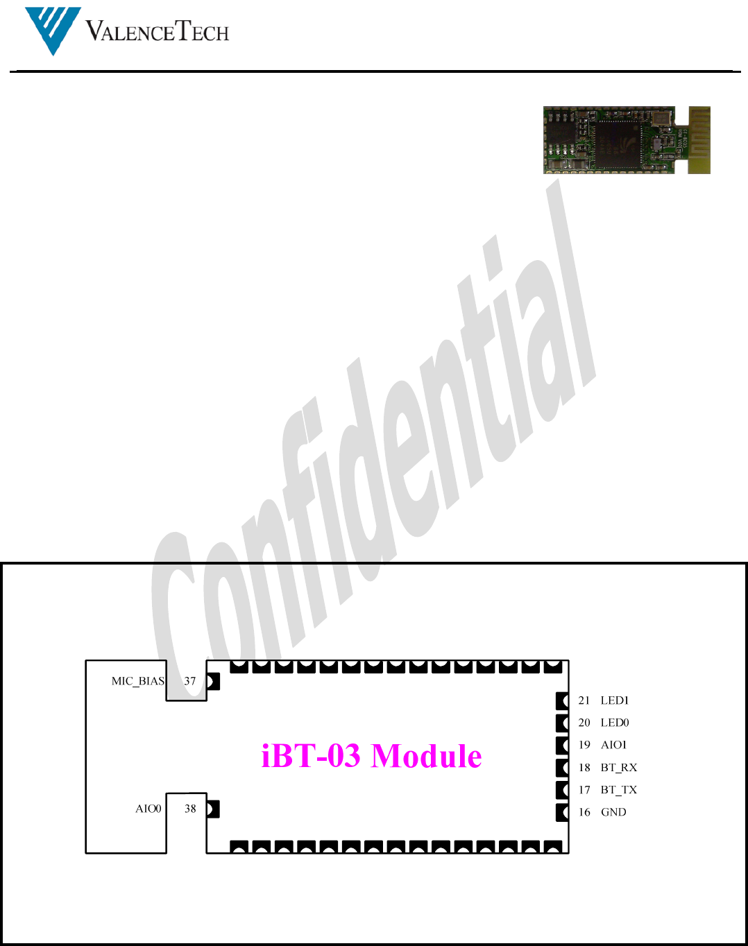
4. Pin Drawing
27 SPI_CSB
22 GND
24 SPI_CLK
36 GND
35 NC
28 PIO12
29 PIO11
30 PIO5
31 PIO3
32 PIO2
33 PIO0
23 RESETB
25 SPI_MISO
26 SPI_MOSI
34 PIO1
3.3V 9
MIC_BP 10
PIO13 8
MIC_BN 11
SPK_LP 5
SPK_LN 4
SPK_RP 7
SPK_RN 6
MIC_AP 2
MIC_AN 3
PIO9 14
PIO4 15
PIO14 13
GND 1
GND 12
Figure 1 iBT-03 Pin Diagram
iBT-03
Bluetooth Module for Audio Application
0.3.01 3 / 7 2012-07-30
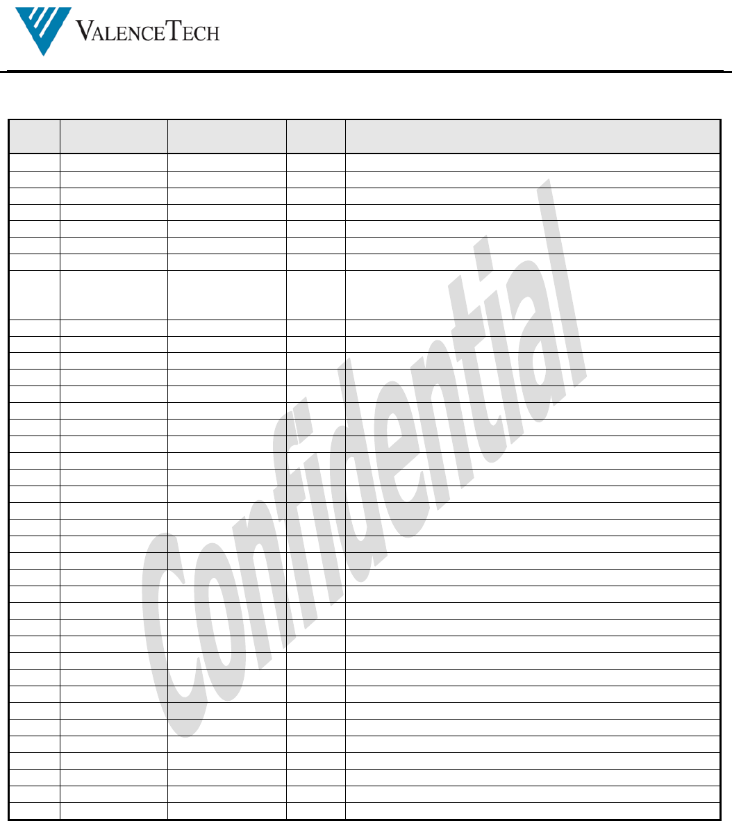
5. Pin Description
Pin
No. Pin Name Application
Usage Pin
Type Pin Descriptions
1 GND GND Ground
2 MIC_AP AI Microphone A Positive Input
3 MIC_AN AI Microphone A Negative Input
4 SPK_LN SPK_LN AO Negative Output of Left Speaker
5 SPK_LP SPK_LP AO Positive Output of Left Speaker
6 SPK_RN SPK_RN AO Negative Output of Right Speaker
7 SPK_RP SPK_RP AO Positive Output of Right Speaker
8 PIO13 STBY / ON I Active High Input for ON / OFF control
When iBT-03 is OFF, a high pulse in this pin will turn it ON.
When iBT-03 is in ON, a high pulse in this pin will turn in OFF
9 3.3V 3.3V 3.3V Supply Input
10 MIC_BP AI Microphone B Positive Input
11 MIC_BN AI Microphone B Negative Input
12 GND GND Ground
13 PIO14 REV I Active High Input for Reverse Control
14 PIO9 PAIR I Perform Pair function
15 PIO4 AMP_SDB O4 Active Low signal for shutting down the external Amplifier
16 GND GND Ground
17 BT_TX O4, PU
UART Data Output
18 BT_RX IS, PD
UART Data Input
19 AIO1 A, B Analog / Programmable I/O
20 LED0 LED0 OD4 Open Drain LED Driver Output
21 LED1 LED1 OD4 Open Drain LED Driver Output
22 GND GND Ground
23 RESETB RESETB IS, PU
Active Low Module Reset. Must be low for > 5mS
24 SPI_CLK SPI_CLK IS, PD
Serial Peripheral Interface Clock
25 SPI_MISO SPI_MISO O4, PD
Serial Peripheral Output Data
26 SPI_MOSI SPI_MOSI IS, PD
Serial Peripheral Input Data
27 SPI_CSB SPI_CSB IS, PU
Active Low Chip Select for Serial Peripheral Interface
28 PIO12 FWD I Active High Input for Forward Control
29 PIO11 PLAY/PAUSE I Active High Input for Play / Pause Control
30 PIO5 VOL_DOWN I Active High Input for Volume Down Control
31 PIO3 CONNECT I Active High Input to activate the Bluetooth connection process
32 PIO2 VOL_UP I Active High Input for Volume Up Control
33 PIO0 B Programmable I/O pin
34 PIO1 B Programmable I/O pin
35 NC Not Connect
36 GND GND Ground
37 MIC_BIAS A Microphone Bias
38 AIO0 A, B Analog Input / Programmable I/O
O4 4mA output pad
OD Open drain output pad
I Input
IS Schmidt Trigger Input
B Bidirectional
SPU Strong Pull-up
SPD Strong Pull-down
WPU Weak Pull-up
WPD Weak Pull-down
A Analog
Table 1 iBT-03 Pin Description Table
iBT-03
Bluetooth Module for Audio Application
0.3.01 4 / 7 2012-07-30
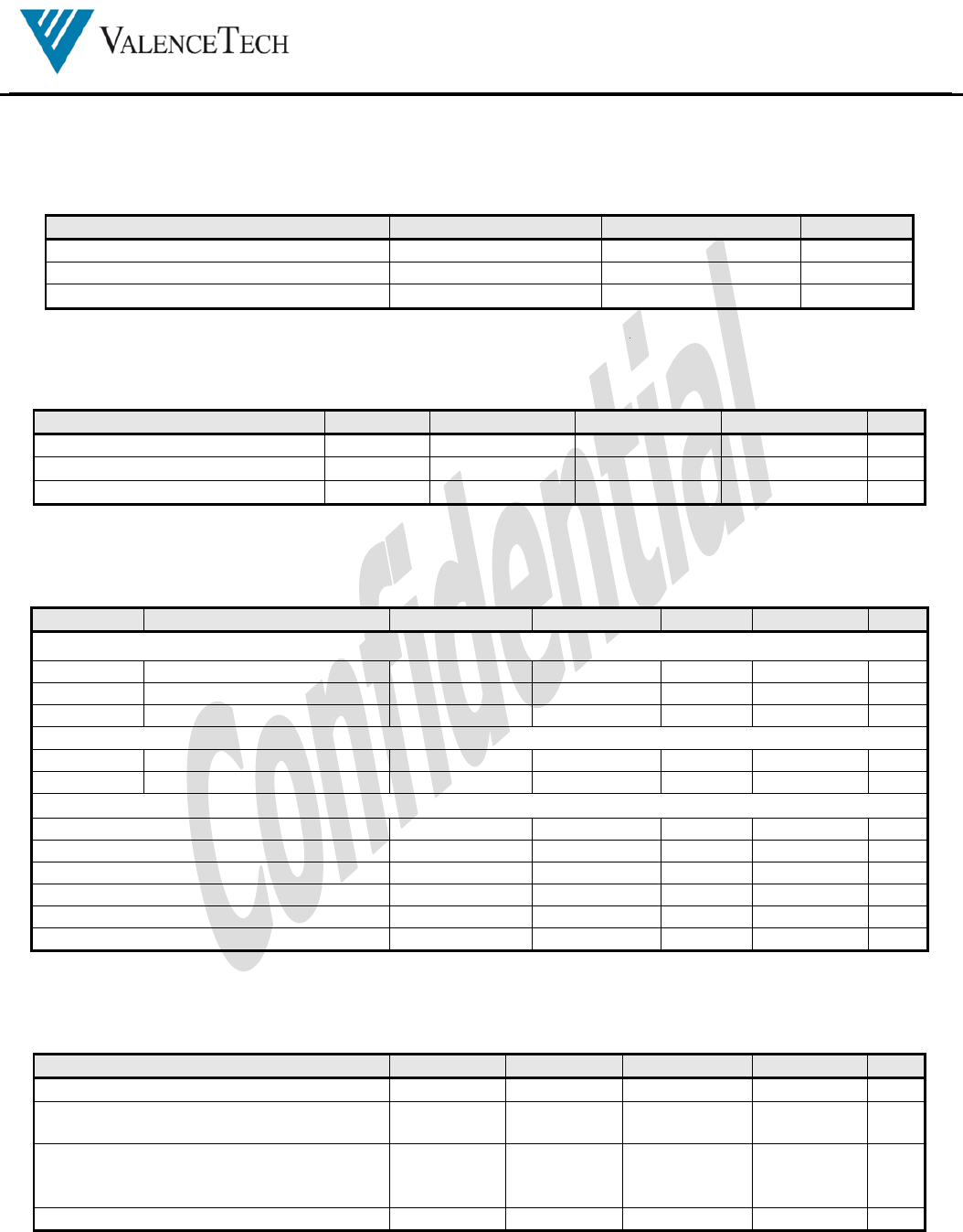
6. Electrical Specification
6.1. Absolute Maximum Rating
Item
Symbol
Rating
Unit
Power Supply Voltage VDD -0.4 to 3.7 V
Peak Current Ipk 0 - 70 mA
Storage Temperature T
STG
-20 to 85 °C
6.2. Recommended Operating Condition
Item
Symbol
M
i
in
Typ
Max
Unit
Power Supply Voltage VDD 3.0 3.3 3.6 V
RF Operating Temperature 0 25 80 °C
Operating Temperature 0 25 55 °C
6.3. Digital Input / Output Port Characteristics
VDD=3.3V, operating temperature = 25 °C unless specified otherwise
Symbol
Parameter
Condition
Min.
Typ.
Max.
Unit
Input Voltage Levels
V
IL
Input low voltage -0.3
0.25*VDD V
V
IH
Input high voltage 0.625*VDD
VDD+0.3 V
V
sch
Schmitt voltage level 0.25*VDD
0.625*VDD
V
Output Voltage Levels
V
OL
Output low voltage I
OL
= -4mA
0.125 V
V
OH
Output high voltage I
OH
= 4mA 0.75*VDD
VDD V
Input and Tri-state Current with
Strong pull-up -100 -40 -10 uA
Strong pull-down 10 40 100 uA
Weak pull-up -5 -1 -0.2 uA
Weak pull-down 0.2 1 5 uA
I/O Pad leakage current -1 0 1 uA
Input Capacitance 1 5 pF
6.4. Operating Current
VDD=3.3V, operating temperature = 25 °C unless specified otherwise
Item
Symbol
M
i
in
Typ
Max
Unit
Standby Mode 0.5 2 mA
Pairing Mode
iBT-03 is discoverable by other devices 1.0 10.0 mA
Idle Mode
iBT-03 is connectable with devices in the
connected list 1.0 10.0 mA
Audio Streaming Mode 40 80.0 mA
iBT-03
Bluetooth Module for Audio Application
0.3.01 5 / 7 2012-07-30
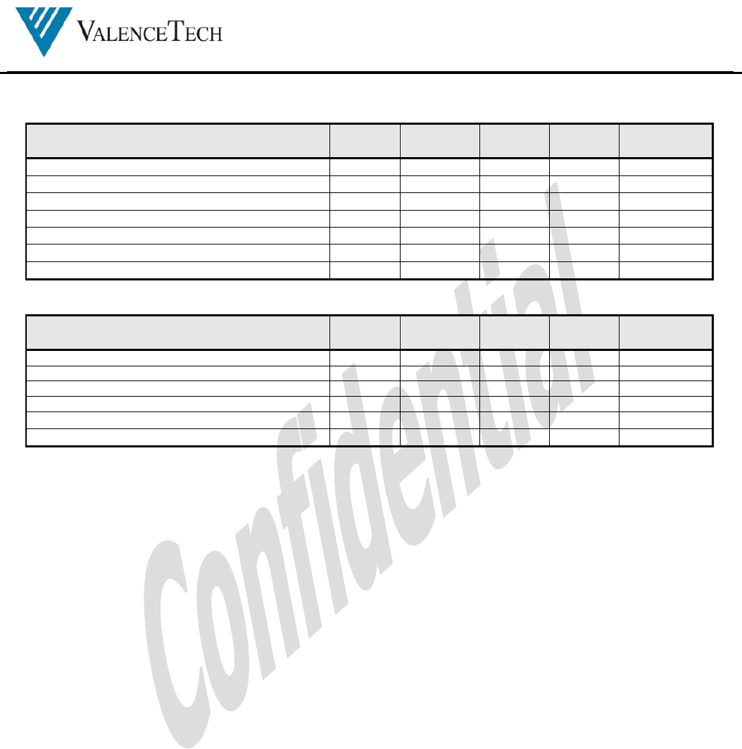
6.5. RF Characteristics
VDD=3.3V, operating temperature = 20 °C unless specified otherwise
Receiver Units Miin Typ Max
Bluetooth
Spec
Sensitivity at 0.1% BER dBm -85 ≦ -70
Maximum Receiver Signal at 0.1% BER dBm -6 ≧-20
C/I Co-Channel dB 10 11 ≦ 11
Adjacent Channel Selectivity C/I – +/-1MHz dB -4 0 ≦ 0
2
nd
Adjacent Channel Selectivity C/I – +2Mhz dB -35 -30 ≦ -30
2
nd
Adjacent Channel Selectivity C/I – -2Mhz dB -21 -20 ≦ -20
3
rd
Adjacent Channel Selectivity C/I – +/-3Mhz dB -45 ≦ -40
VDD=3.3V, operating temperature = 20 °C unless specified otherwise
Transmitter Units Miin Typ Max
Bluetooth
Spec
RF Output Power dBm 0 2 4 -6 to +4
RF Power Control Range dB 16 35 > 16
RF Power Range Control Resolution dB 1.8 -
20dB Bandwidth for modulated Carrier kHz 879 1000 < 1000
2
nd
Adjacent Channel Power (+/- 2Mhz) dBm -35 -20 ≦ -20
3
rd
Adjacent Channel Power (+/- 3Mhz) dBm -45 -40 ≦ -40
iBT-03
Bluetooth Module for Audio Application
0.3.01 6 / 7 2012-07-30
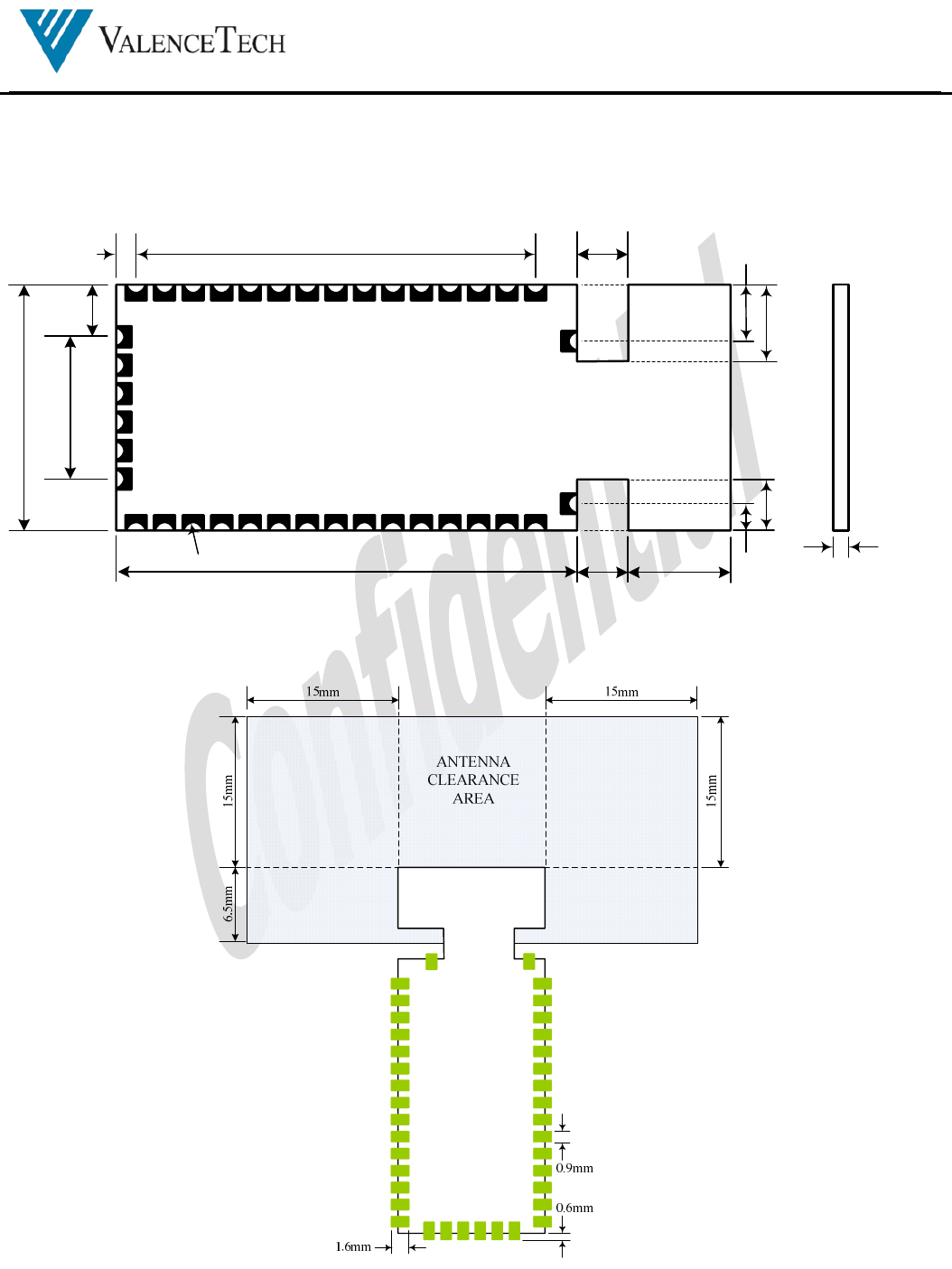
7. Module Dimension and PCB Layout Guideline
7.1. Module Dimension
1.46mm x 14 = 20.44mm
0.95mm
23.24mm
11.94mm
iBT-03 Module
(Top View)
5.33mm
2.54mm
2.41mm
2.97mm
3.81mm
2.54mm
1.66mm
2.54mm
1.46x5 = 7.3mm
R=0.38mm 0.8mm
7.2. PCB Layout Guideline

iBT-03
Bluetooth Module for Audio Application
0.3.01 7 / 7 2012-07-30
8. FCC Statement
NOTICE:
This device complies with Part 15 of the FCC Rules. Operation is subject to the following two conditions: (1) this device may not
cause harmful interference, and (2) this device must accept any interference received, including interference that may cause
undesired operation.
Changes or modifications made to this equipment not expressly approved by ValenceTech Limited may void the FCC
authorization to operate this equipment.
This equipment has been tested and found to comply with the limits for a Class B digital device, pursuant to Part 15 of the FCC
Rules. These limits are designed to provide reasonable protection against harmful interference in a residential installation. This
equipment generates, uses and can radiate radio frequency energy and if not installed and used in accordance with the instructions,
may cause harmful interference to radio communications. However, there is no guarantee that interference will not occur in a
particular installation. If this equipment does cause harmful interference to radio or television reception, which can be determined
by turning the equipment off and on, the user is encouraged to try to correct the interference by one or more of the following
measures:
Reorient or relocate the receiving antenna.
Increase the separation between the equipment and receiver
Connect the equipment into an outlet on a circuit different from that to which the receiver is connected.
Consult the dealer or an experienced radio/TV technician for help
Radiofrequency radiation exposure information:
This equipment complies with FCC radiation exposure limits set forth for an uncontrolled environment. Please see the RF
Exposure information. This transmitter must not be co-located or operating in conjunction with any other antenna or transmitter.
This device should be installed and operated with a minimum distance of 20cm between the antenna and all persons.
Label requirements:
Contains Transmitter Module FCC ID: ORP-IBT-03
Host use instruction:
The module must install and work with a speaker,
the speaker's manufacturer is ValenceTech Limited.
The Host model name: IBT03 BLUETOOTH SPEAKER SYSTEM
The Host Brand Name: ValenceTech
The host is a fixed device and the antenna used with this host should be installed and operated with a minimum distance of
20cm from all persons.
FCC RF Exposure Requirement
1. At least 20cm separation distance between the antenna and the user's body must be maintained at all times.
And must not transmit simultaneously with any other antenna or transmitter, except in accordance with FCC multi transmitter
product procedures.
2. To comply with FCC regulations limiting both maximum RF output power and human exposure to RF radiation, the maximum
antenna gain including cable loss in a mobile-only exposure condition must not exceed 0dBi in the 2.4G band.
3. A user manual with the end product must clearly indicate the operating requirements and conditions that must
be observed to ensure compliance with current FCC RF exposure guidelines.
Note: If this module is intended for use in a portable device, you are responsible for separate approval to satisfy the SAR
requirements of FCC Part 2.1093.

GOODOCOM Technologies Confidential
Please be noticed following information and instructions should be
placed in the end-user’s operating manual
The iBT-03 Module has been granted as limited modular approval for mobile applications. iBT-03
Module must be installed in the designated host as specified in this manual.
1. Separate approval is required for all other operating configurations, including portable configurations with
respect to 2.1093 and different antenna configurations.
2. The iBT-03 Module and its antenna must not be co-located or operating in
conjunction with any other transmitter or antenna within a host device. This equipment complies with
FCC RF radiation exposure limits set forth for an uncontrolled environment.
3. A label must be affixed to the outside of the end product into which the iBT-03
module is incorporated, with a statement similar to the following: For iBT-03:
This device contains FCC ID: ORP-IBT-03.
4. The module shall be in non-detachable construction protection into the finished products, so that the
end-user has to destroy the module while remove or install it.
5. This module is to be installed only in mobile or fixed applications. According to FCC part 2.1091(b)
definition of mobile and fixed devices is:.
Mobile device:
A mobile device is defined as a transmitting device designed to be used in other than fixed locations and to
generally be used in such a way that a separation distance of at least 20 centimeters is normally maintained
between the transmitter’s radiating structure(s) and the body of the user or nearby persons. In this context,
the term ‘‘fixed location’’ means that the device is physically secured at one location and is not able to be
easily moved to another location.
Portable device:
For purposes of this section, a portable device is defined as a transmitting device designed to be used so that
the radiating structure(s) of the device is/are within 20 centimeters of the body of the user.
6. Separate approval is required for all other operating configurations, including portable configurations
with respect to FCC Part 2.1093 and different antenna configurations.
7. A certified modular has the option to use a permanently affixed label, or an electronic label. For a permanently
affixed label, the module must be labelled with an FCC ID: ORP-IBT-03. The OEM manual must provide
clear instructions explaining to the OEM the labelling requirements, options and OEM user manual instructions
that are required
For a host using a this FCC certified modular with a standard fixed label, if (1) the module’s FCC ID is not
visible when installed in the host, or (2) if the host is marketed so that end users do not have
straightforward commonly used methods for access to remove the module so that the FCC ID of
the module is visible; then an additional permanent label referring to the enclosed module:
“Contains Transmitter Module FCC ID: ORP-IBT-03” or “Contains FCC ID: ORP-IBT-03” must
be used. The host OEM user manual must also contain clear instructions on how end users can
find and/or access the module and the FCC ID.
8. Host product is required to comply with all applicable FCC equipment authorizations regulations,
requirements and equipment functions not associated with the transmitter module portion. compliance must be

GOODOCOM Technologies Confidential
demonstrated to regulations for other transmitter components within the host product; to requirements for
unintentional radiators (Part 15B). To ensure compliance with all non-transmitter functions the host manufacturer
is responsible for ensuring compliance with the module(s) installed and fully operational. If a host was previously
authorized as an unintentional radiator under the Declaration of Conformity procedure without a transmitter
certified module and a module is added, the host manufacturer is responsible for ensuring that the after the module
is installed and operational the host continues to be compliant with the Part 15B unintentional radiator
requirements. Since this may depend on the details of how the module is integrated with the host, we suggest the
host device to recertify part 15B to ensure complete compliance with FCC requirement: Part 2 Subpart J
Equipment Authorization Procedures , KDB784748 D01 v07, and KDB 997198 about importation of radio
frequency devices into the United States.

OEM RESPONSIBILITIES TO COMPLY WITH FCC REGULATIONS
The iBT-03 Module has been certified for integration into products only by OEM
integrators under the following conditions:
This device is granted for use in Mobile only configurations in which the antennas
used for this transmitter must be installed to provide a separation distance of
at least 20cm from all person and not be co-located with any other transmitters
except in accordance with FCC and Industry Canada multi-transmitter product
procedures.
As long as the two conditions above are met, further transmitter testing will not
be required.
However, the OEM integrator is still responsible for testing their end-product
for any additional compliance requirements required with this module installed
(for example, digital device emissions, PC peripheral requirements, etc.).
IMPORTANT NOTE: In the event that these conditions cannot be met (for certain
configurations or co-location with another transmitter), then the FCC and Industry
Canada authorizations are no longer considered valid and the FCC ID and IC
Certification Number cannot be used on the final product. In these circumstances,
the OEM integrator will be responsible for re-evaluating the end product (including
the transmitter) and obtaining a separate FCC and Industry Canada authorization.
OEM LABELING REQUIREMENTS FOR END-PRODUCT
The iBT-03 module is labeled with its own FCC ID Certification Number. The FCC
ID certification numbers are not visible when the module is installed inside another
device, as such the end device into which the module is installed must display
a label referring to the enclosed module. The final end product must be labeled
in a visible area with the following:
“Contains Transmitter Module FCC ID: ORP-IBT-03”
or
“Contains FCC ID: ORP-IBT-03”
The OEM of the iBT-03 Module must only use the approved antenna(s) listed above,
which have been certified with this module.
The device iBT-03 carries FCC authorization and is marked with the FCC ID Number.
Whilst any device into which this authorized module is installed will not normally
be required to obtain FCC authorization, this does not preclude the possibility

that some other form of authorization or testing may be required for the finished
device.
OEM END PRODUCT USER MANUAL STATEMENTS
The OEM integrator should not to provide information to the end user regarding
how to install or remove this RF module or change RF related parameters in the
user manual of the end product.
If this module is intended for use in a portable device, you are responsible for
separate approval to satisfy the SAR requirements of FCC Part 2.1093.
The user manual for the end product must include the following information in a
prominent location:
This device is granted for use in Mobile only configurations in which the antennas
used for this transmitter must be installed to provide a separation distance of
at least 20cm from all person and not be co-located with any other transmitters
except in accordance with FCC and Industry Canada multi-transmitter product
procedures.
The end product with an embedded FCC ID:ORP-IBT-03 Module may also need to pass
the FCC Part 15 unintentional emission testing requirements and be properly
authorized per FCC Part 15.
The labeling instructions of finished products refer to following requirements:
A certified modular has the option to use a permanently affixed label, or an
electronic label (see Electronic Labelling below). For a permanently affixed label,
the module must be labelled with an FCC ID - Section 2.926 (see Certification
(labelling requirements) above). The OEM manual must provide clear instructions
explaining to the OEM the labelling requirements,options and OEM user manual
instructions that are required (see next paragraph).
For a host using a certified modular with a standard fixed label, if (1) the module’
s FCC ID is not visible when installed in the host, or (2) if the host is marketed
so that end users do not have straightforward commonly used methods for access
to remove the module so that the FCC ID of the module is visible; then an additional
permanent label referring to the enclosed module:
“Contains Transmitter Module FCC ID: ORP-IBT-03”or “Contains FCC ID: ORP-IBT-03”
must be used. The host OEM user manual must also contain clear instructions on
how end users can find and/or access the module and the FCC ID.
Other user manual statements may apply.

iBT-03
Bluetooth Module for Audio Application
0.3.01 8 / 7 2012-07-30
Valence Semiconductor Design Ltd.
Unit 1, 20/F., APEC Plaza, 49 Hoi Yuen Road, Kwun Tong, Hong Kong
Tel: (852) 2797 3288 Fax: (852) 2776 7770
http://www.valencetech.com
The information in this publication is believed to be accurate in all respects at the time of publication but is subject to change without notice. Valence
Semiconductor Design Ltd. assumes no responsibility for errors and omissions, and disclaims responsibility for any consequences resulting from the use of
information included herein. Additionally, Valence Semiconductor Design Ltd. assumes no responsibility for the functioning of undocumented features or
parameters.