Vantage Controls CR1000 Controller for the automation system User Manual C Box RACK 1
Vantage Controls Inc. Controller for the automation system C Box RACK 1
UserManual.wiki
>
Vantage Controls
>
CR1000 User Manual
installation and users manual
Navigation menu
Upload a User Manual
Namespaces
Wiki Guide
HTML
PDF
Info
Views
User Manual
Discussion / Help
Navigation
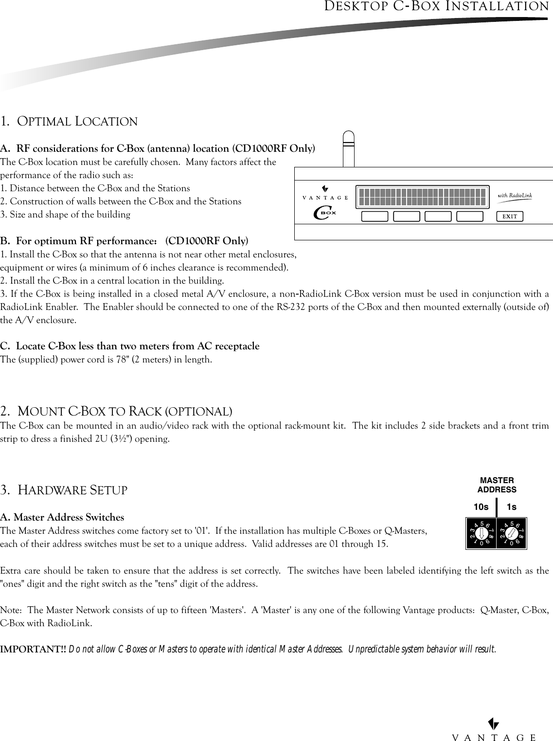
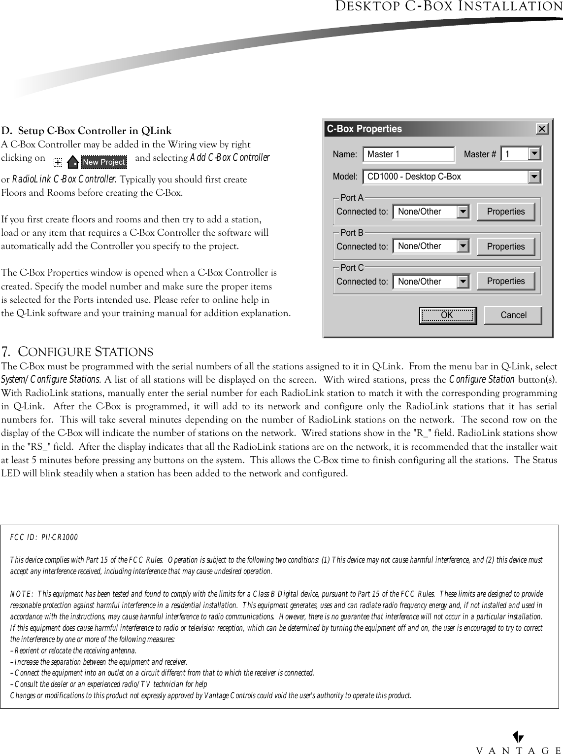
![VANTAGEEXIT BUTTONAUXILLARY POWERMASTER ADDRESSTERMINATION SWITCHRESET SWITCHRS-232 PORT-C [CD1000 ONLY]ANTENNA[CD1000RF ONLY]AC POWER INLETRS-232 PORT-ARS-232 PORT-BMASTER BUSSTATION BUSDIAGNOSTIC LCD DISPLAYANTENNA [CD1000RF ONLY]4th BUTTON3rd BUTTON2nd BUTTON1st BUTTON17"2"RS-232 PORTDESKTOP C-BOX INSTALLATION 1 2 3 4 5 1 2 3 4 51 2 1 2 1 2 1 2 1 2RS-232+24V DC+12V DCGNDTXARXARTSACTSAGNDTXBRXBRTSBCTSBT/R+T/R-T/R+T/R-PORT-AMASTER BUS STATION BUSCLASS 2RUN-1 RUN-2PORT-BRESET100-250V AC50/60Hz MASTERADDRESS MASTERNETWORKTERMINATIONRS-232PORT-CONOFF10s 1s](https://usermanual.wiki/Vantage-Controls/CR1000/User-Guide-219048-Page-3.png)