Vantage Controls CR1000 Controller for the automation system User Manual C Box RACK 1
Vantage Controls Inc. Controller for the automation system C Box RACK 1
installation and users manual
VANTAGE
INSTALLATION GUIDE FOR
CD1000 & CD1000RF
INSTALLATION GUIDE OVERVIEW
I. Locate C-Box in an optimal location for installation and performance
A. RF antenna considerations
B. AC power outlet
II. Mount C-Box
III. Setup hardware
A. Master Address
B. Master Network Termination
IV. Wire low-voltage connections (optional)
A. Master Bus
B. Station Bus
C. RS-232
V. Plug C-Box into AC receptacle
VI. Setup software
VII. Configure stations
DESKTOP C-BOX
VANTAGE
OWNER'S WARRANTY
RISK OF ELECTRIC SHOCK.
DO NOT REMOVE SCREWS
EXCEPT SPECIFIED USER
SERVICE SCREW.
CAUTION: TO REDUCE THE RISK OF ELECTRIC SHOCK,
DO NOT REMOVE COVER.
NO USER-SERVICEABLE PARTS EXCEPT LAMP UNIT.
REFER SERVICING TO QUALIFIED SERVICE
PERSONNEL.
The lightning flash with arrowhead symbol, within
an equilateral triangle, is intended to alert the
user to the presence of uninsulated "dangerous
voltage" within the product's enclosure that may
be of sufficient magnitude to constitute a risk or
electric shock to persons.
The exclamation point within a triangle is
intended to alert the user to the presence of
important operating and maintenance (servicing)
instructions in the literature accompanying the
product.
WARNING: In order to comply with the FCC RF exposure requirements, this product must be installed and
operated in such a way that a minimum separation distance of 20 cm (approximately 8 inches) is maintained from
the antenna to any persons. Operations that do not meet these requirements must be avoided.
WARNING: To reduce the risk of fire or electric shock, do not expose this product to rain or moisture.
Note: All time periods mentioned in this Attachment refer to time elapsed from date of invoice to dealer.
1. VANTAGE Q-Series products are warranted to be free from defects in materials and workmanship for a period of five years.
2. VANTAGE Vision products are warranted to be free from defects in materials and workmanship for a period of two years.
3. This warranty does not apply to any defect arising from abnormal use, abuse, negligence, equipment alteration, improper
installation, products misapplication or acts of God.
4. Products that VANTAGE obtains through third parties (such as remotes and sensors) maintain the original equipment
manufacturer's warranty, and are not covered by VANTAGE's standard product warranty.
5. VANTAGE reserves the right, to determine whether products have been subject to abnormal use, abuse, negligence, equipment
alteration, improper installation, product misapplication or acts of God.
6. VANTAGE reserves the right, to inspect all returned components to determine the cause of the malfunction and to determine if it
will be repaired or replaced under the warranty agreement.
7. VANTAGE shall not be liable for incidental or consequential damages, including, but not limited to, installation or replacement
labor costs, and disclaims the implied warranty of merchantability and fitness for a particular purpose. Some states do not allow
limitations on duration of implied warranty periods and do not allow the exclusion or limitation of incidental or consequential
damages. Some of the above limitations may not apply to every purchaser.
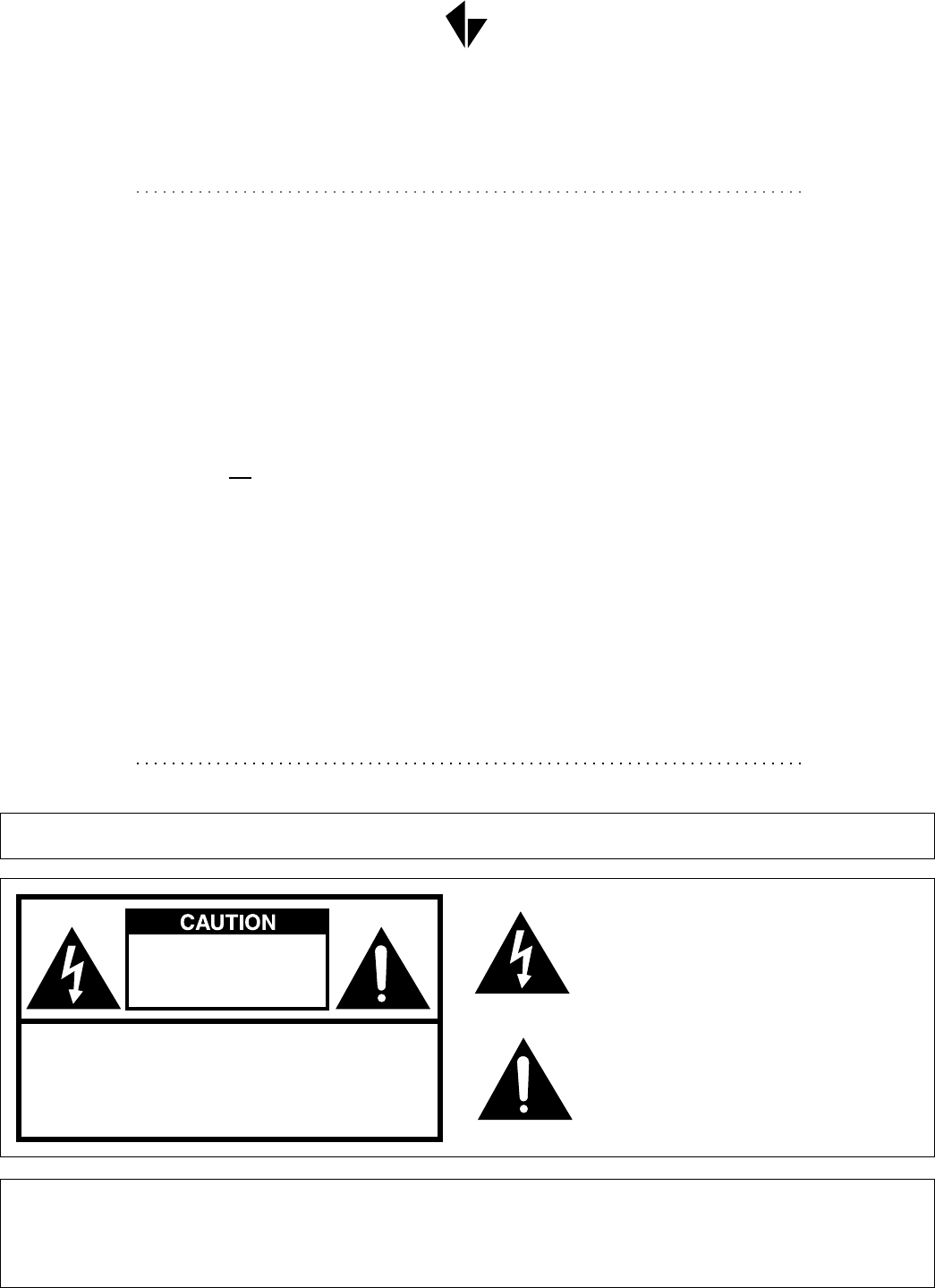
VANTAGE
EXIT BUTTON
AUXILLARY POWER
MASTER ADDRESS
TERMINATION SWITCH
RESET SWITCH
RS-232 PORT-C [CD1000 ONLY]
ANTENNA
[CD1000RF ONLY]
AC POWER INLET
RS-232 PORT-A
RS-232 PORT-B
MASTER BUS
STATION BUS
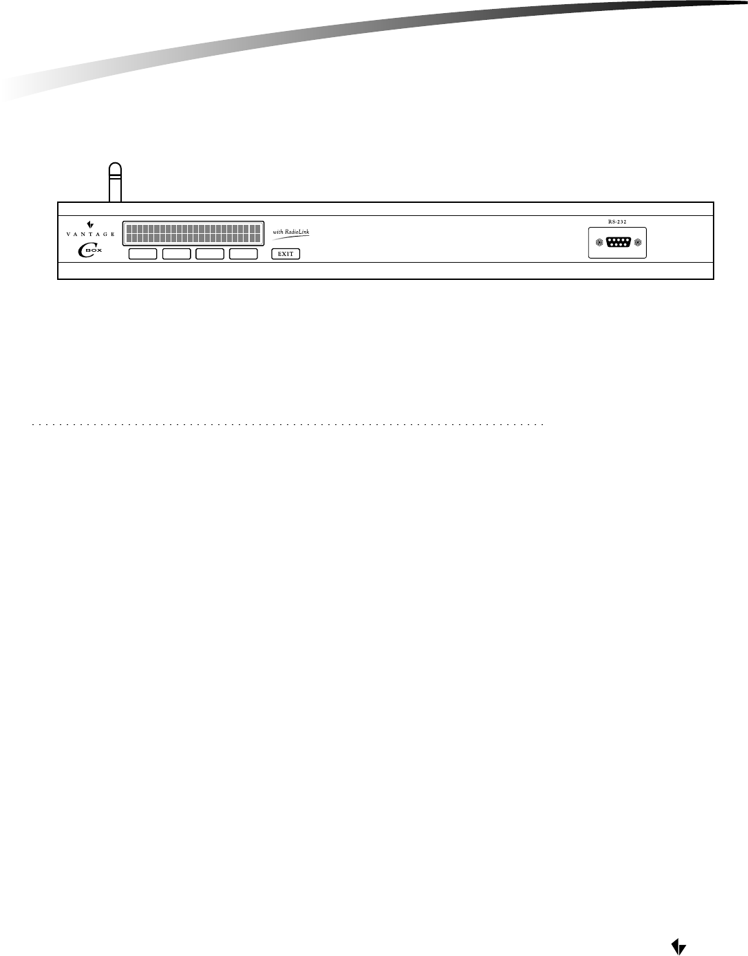
DIAGNOSTIC LCD DISPLAY
ANTENNA [CD1000RF ONLY]
4th BUTTON
3rd BUTTON
2nd BUTTON
1st BUTTON
17"
2"
RS-232 PORT
DESKTOP C-BOX INSTALLATION
1 2 3 4 5 1 2 3 4 5
1 2 1 2 1 2 1 2 1 2
RS-232
+24V DC
+12V DC
GND
TXA
RXA
RTSA
CTSA
GND
TXB
RXB
RTSB
CTSB
T/R+
T/R-
T/R+
T/R-
PORT-A
MASTER BUS STATION BUS
CLASS 2
RUN-1 RUN-2
PORT-B
RESET
100-250V AC
50/60Hz
MASTER
ADDRESS MASTER
NETWORK
TERMINATION
RS-232
PORT-C
ON
OFF
10s 1s
VANTAGE
1. OPTIMAL LOCATION
A. RF considerations for C-Box (antenna) location (CD1000RF Only)
The C-Box location must be carefully chosen. Many factors affect the
performance of the radio such as:
1. Distance between the C-Box and the Stations
2. Construction of walls between the C-Box and the Stations
3. Size and shape of the building
B. For optimum RF performance: (CD1000RF Only)
1. Install the C-Box so that the antenna is not near other metal enclosures,
equipment or wires (a minimum of 6 inches clearance is recommended).
2. Install the C-Box in a central location in the building.
3. If the C-Box is being installed in a closed metal A/V enclosure, a non-RadioLink C-Box version must be used in conjunction with a
RadioLink Enabler. The Enabler should be connected to one of the RS-232 ports of the C-Box and then mounted externally (outside of)
the A/V enclosure.
C. Locate C-Box less than two meters from AC receptacle
The (supplied) power cord is 78" (2 meters) in length.
2. MOUNT C-BOX TO RACK (OPTIONAL)
The C-Box can be mounted in an audio/video rack with the optional rack-mount kit. The kit includes 2 side brackets and a front trim
strip to dress a finished 2U (3½") opening.
3. HARDWARE SETUP
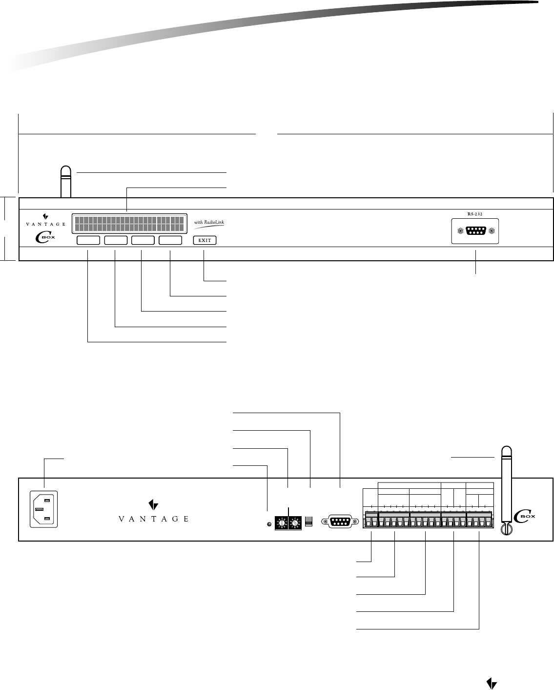
A. Master Address Switches
The Master Address switches come factory set to '01'. If the installation has multiple C-Boxes or Q-Masters,
each of their address switches must be set to a unique address. Valid addresses are 01 through 15.
Extra care should be taken to ensure that the address is set correctly. The switches have been labeled identifying the left switch as the
"ones" digit and the right switch as the "tens" digit of the address.
Note: The Master Network consists of up to fifteen 'Masters'. A 'Master' is any one of the following Vantage products: Q-Master, C-Box,
C-Box with RadioLink.
IMPORTANT!! Do not allow C-Boxes or Masters to operate with identical Master Addresses. Unpredictable system behavior will result.
DESKTOP C-BOX INSTALLATION
MASTER
ADDRESS
10s 1s
VANTAGE
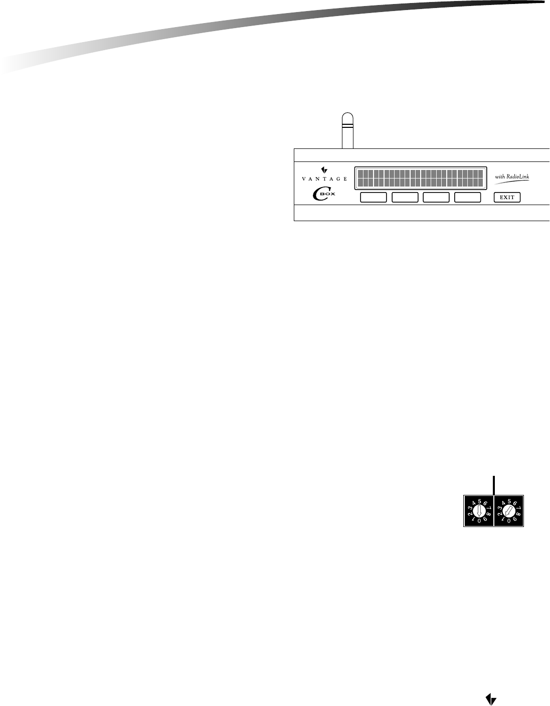
B. Master Network Termination Switch
Set the Master Network Termination Switch to "ON" if the C-Box is physically at the end of a 'daisy-chained'
or 'home-run' Master Network.
Set the Master Network Termination Switch to "OFF" if the C-Box is in the middle of a 'daisy-chained'
Master Network.
A C-Box that is not physically wired to other C-Boxes or Masters MUST have its termination switch set to 'ON'.
C. Reset Button
When the reset button is pressed, the C-Box and all connected stations will reset. RF stations will reinitialize and
be inoperable for a few minutes.
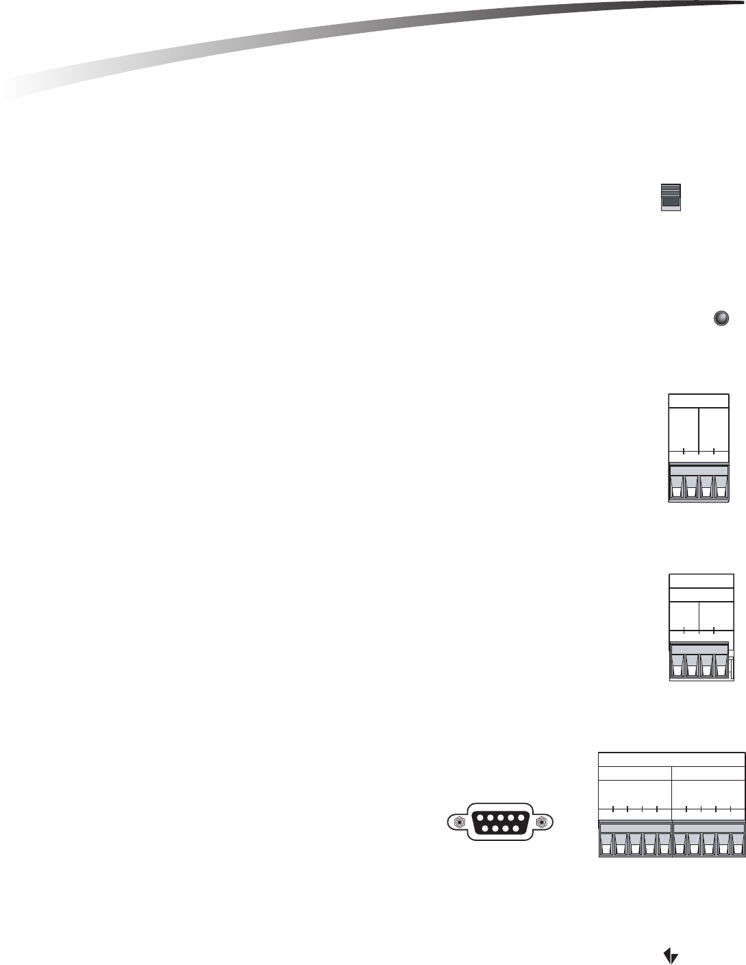
4. WIRE LOW-VOLTAGE CONNECTIONS (Optional)
A. Master Bus
The C-Box may be included in a 'wired' Master Network. Two conductor 18AWG wire should be used. 1000 total
feet of wire is the maximum allowed, regardless of the number of Masters or C-Boxes on the network. See the sections
detailing the Master Address Switches and the Master Network Termination Switch.
IMPORTANT!! The Master Network is polarized. Extra care MUST be taken to connect this master's T/R+ terminal
to the next master's T/R+ terminal, as well as this master's T/R- terminal to the next master's T/R-terminal.
B. Station Bus Network
The C-Box Station Bus can be used to control up to fifty "wired" stations. These stations are in addition
to the "wireless" stations. Any of the stations currently available from Vantage may be connected to this bus,
such as LCD, Low-voltage Relay, Contact Input, RS-232 and DMX Stations and all the varieties of keypad stations.
Two conductor 18AWG wire should be used. 1,000 total feet of wire is the maximum allowed on each run, regardless
of the number of stations on the network.
NOTE: The station network is not polarized.
C. RS-232
The C-Box has four* RS-232 Ports. The port on the face of the chassis is the
Diagnostic Port and is used for temporary connection to a laptop computer
for programming or updating the Vantage System. The remaining three
ports A, B, and C, are available for permanent connection to third party
equipment such as a video projector, audio/video matrix switcher or security
system. A null modem, cross type cable should be used (Diagnostic Port and Port-C).
*IMPORTANT!! Port C is NOT available on the C-Box with RadioLink (CD1000RF).
DESKTOP C-BOX INSTALLATION
RESET
MASTER
NETWORK
TERMINATION
ON
OFF
1 2 1 2
STATION BUS
CLASS 2
RUN-1 RUN-2
1 2 3 4 5 1 2 3 4 5
RS-232
GND
TXA
RXA
RTSA
CTSA
GND
TXB
RXB
RTSB
CTSB
PORT-A PORT-B
RS-232
PORT-C
1 2 1 2
T/R+
T/R-
T/R+
T/R-
MASTER BUS
VANTAGE
The C-Box typically uses RX, TX and GND for RS-232 communications. RTS and CTS are also implemented for hardware that
requires them.
The default protocol for RS-232 communication is:
Signal Format: Conforms to RS-232 C standard
Baud: 19200
Parity: none
Total Bits: 8
Stop Bits: 1
Flow Control: None
D. NOTE
The C-Box provides +24VDC at 100mA and +12VDC at 250mA. These voltages are available for external hardware such as motion
detectors, light sensors, etc.
C-Box low-voltage circuits are classified as Class 2 circuits (USA). As Class 2 circuits, they comply with the requirements of NFPA 70, National
Electrical Code (NEC). When installing and wiring to these C-Boxes, follow all applicable national and/or local wiring regulations. External
connections to any low-voltage C-Box terminal must be from a Listed Class 2 Source.
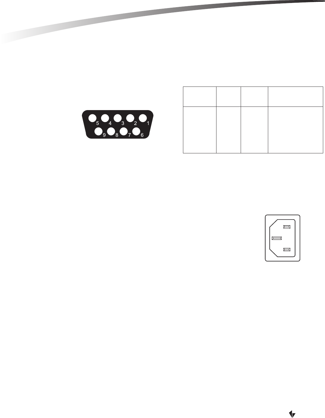
5. PLUG C-BOX INTO AC RECEPTACLE
After carefully checking all low-voltage wiring, (if any), proceed to plug the C-Box into a grounded AC
receptacle using the supplied power cord. Although not suggested, if additional length is required, a
longer cord may be used as long as it contains a ground conductor.
6. SETUP SOFTWARE
A. LCD Control & Menu Structure
Overview:
The front panel of the C-Box has five buttons that allow control of, or status of the following elements:
1. Set Load Levels By:
a. Master
b. Module
c. Load
d. Level, Toggle or Increment (10%)
2. Set Station Switch Status (not implemented)
3. Set Master Time
a. Time
i. Month/Date/Year/Hour/Minute/Second
b. Calibrate Time Clock
i. '+' or '-' number of seconds per day
4. Diagnostics of:
a. Master
i. Version
ii. Network Communications
iii. TeleAccess Installed Status: Yes/No
iv. Generate - Displays Master Address
b. Station (not implemented)
c. RS232
i. Displays Current RS 232 Settings Only, i.e. 19200, N, 8, 1
d. Gen (Generate)
i. Load Backup Flash (reprogram C-Box from Flash Memory)
FRONT VIEW OF PORT-C
& DIAGNOSTIC PORT
C-BOX RS-232 CONNECTIONS
Signal
Name
RX Data In
TX Data Out
GND
CTS
RTS
Vantage
DB9 Pin
2
3
5
7
8
Screw
Terminals
3
2
1
4
5
External Devices
Data out (TX)
Data In (RX)
Ground (GND)
Handshake Out (RTS)
Handshake In (CTS)
100-250V AC
50/60Hz
DESKTOP C-BOX INSTALLATION

Implementation:
If navigation stops working press the reset button on the C-Box. (Always do step "A" first before starting each of the steps below) Press any
of the four buttons on the C-Box to access the menu functions.
1. How to set Load Levels:
a. Press arrow keys so the cursor is on the L in Load, then press the button under Sel.
b. Move the cursor to Ma1 (Master#), Mo1 (Module#), Ld1 (load#). Each of these selections can be changed by pressing the Inc
(increment) button when the cursor is on that item, i.e. change the Ma1 to Ma2, etc.
c. When selections are made the load can be toggled or incremented in 10% steps.
2. How to set Station Switch Status:
a. Currently not implemented
3. How to set or calibrate Master Controller Time:
a. Press arrow keys so the cursor is on the T in Time, then press the button under Sel.
i. To set/change the time and date on the C-Box, place the cursor on Set and press Sel. Each component of the date
and time can be decremented or incremented.
ii. To calibrate the C-Box's internal clock, place the cursor on Calibrate and press Sel. The internal C-Box clock speed
can be decremented or incremented to + or - 58 seconds daily.
4. How to run Diagnostics and Reports:
a. Press the arrow keys so the cursor is on the D in Diag, then press Sel.
i. For Master diagnostics place the cursor on Mast and press Sel.
(1) Select Ver for Master Firmware Version.
(2) Select Net for network communications.
(3) Select Tele to see if TeleAccess has been installed.
(4) Select Gen to see the Master Address.
ii. For Station diagnostics (not implemented)
iii. For RS232 diagnostics place the cursor on RS232 and press Sel.
The current port, baud rate, parity, Total bits, and Stop bits are displayed.
iv. For Gen diagnostics place the cursor on Gen and press Sel.
With the cursor on Ldbk Flsh, press Sel and the C-Box will be reprogrammed from the Backup Flash. When
display reads "Backup Flash Loaded," press Exit until display returns to normal.
B. Connect to computer
Connection to the computer can be temporary using the front diagnostic RS-232 Port, or permanently wired to the C-Box using Port-A,
B, or C. (Port-C is not available on the CD1000RF)
C. Update Firmware
The C-Box may be shipped with a firmware update. The first time you connect to the C-Box Q-Link may prompt you to update the
system firmware to the latest version.
VANTAGE
DESKTOP C-BOX INSTALLATION
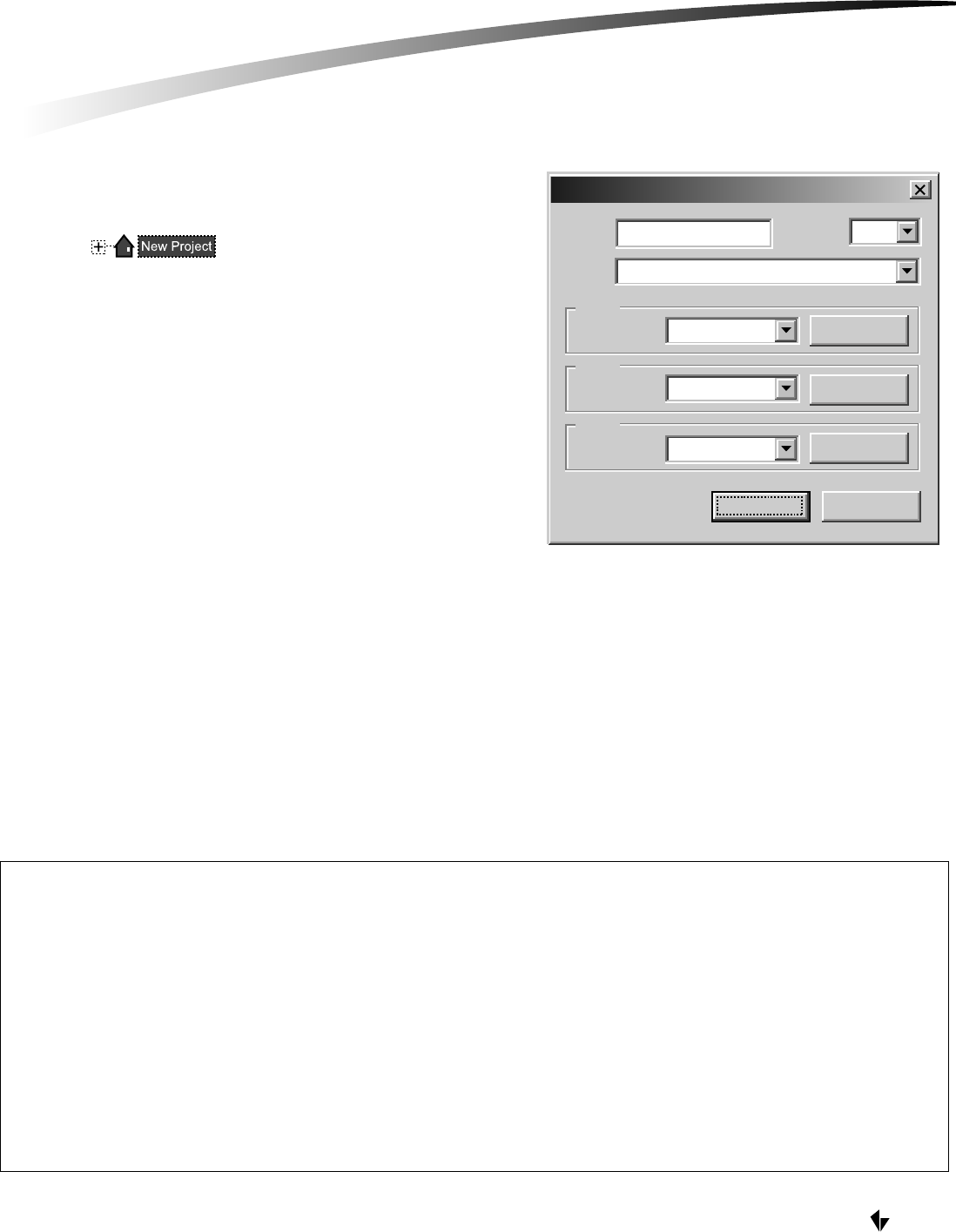
D. Setup C-Box Controller in QLink
A C-Box Controller may be added in the Wiring view by right
clicking on and selecting Add C-Box Controller
or RadioLink C-Box Controller. Typically you should first create
Floors and Rooms before creating the C-Box.
If you first create floors and rooms and then try to add a station,
load or any item that requires a C-Box Controller the software will
automatically add the Controller you specify to the project.
The C-Box Properties window is opened when a C-Box Controller is
created. Specify the model number and make sure the proper items
is selected for the Ports intended use. Please refer to online help in
the Q-Link software and your training manual for addition explanation.
7. CONFIGURE STATIONS
The C-Box must be programmed with the serial numbers of all the stations assigned to it in Q-Link. From the menu bar in Q-Link, select
System/Configure Stations. A list of all stations will be displayed on the screen. With wired stations, press the Configure Station button(s).
With RadioLink stations, manually enter the serial number for each RadioLink station to match it with the corresponding programming
in Q-Link. After the C-Box is programmed, it will add to its network and configure only the RadioLink stations that it has serial
numbers for. This will take several minutes depending on the number of RadioLink stations on the network. The second row on the
display of the C-Box will indicate the number of stations on the network. Wired stations show in the "R_" field. RadioLink stations show
in the "RS_" field. After the display indicates that all the RadioLink stations are on the network, it is recommended that the installer wait
at least 5 minutes before pressing any buttons on the system. This allows the C-Box time to finish configuring all the stations. The Status
LED will blink steadily when a station has been added to the network and configured.
Name: Master 1 1Master #
Model: CD1000 - Desktop C-Box
Port A
Connected to: None/Other
None/Other
None/Other
Properties
Properties
Properties
CancelOK
Connected to:
Connected to:
Port B
Port C
C-Box Properties
VANTAGE
FCC ID: PII-CR1000
This device complies with Part 15 of the FCC Rules. Operation is subject to the following two conditions: (1) This device may not cause harmful interference, and (2) this device must
accept any interference received, including interference that may cause undesired operation.
NOTE: This equipment has been tested and found to comply with the limits for a Class B Digital device, pursuant to Part 15 of the FCC Rules. These limits are designed to provide
reasonable protection against harmful interference in a residential installation. This equipment generates, uses and can radiate radio frequency energy and, if not installed and used in
accordance with the instructions, may cause harmful interference to radio communications. However, there is no guarantee that interference will not occur in a particular installation.
If this equipment does cause harmful interference to radio or television reception, which can be determined by turning the equipment off and on, the user is encouraged to try to correct
the interference by one or more of the following measures:
-- Reorient or relocate the receiving antenna.
-- Increase the separation between the equipment and receiver.
-- Connect the equipment into an outlet on a circuit different from that to which the receiver is connected.
-- Consult the dealer or an experienced radio/TV technician for help
Changes or modifications to this product not expressly approved by Vantage Controls could void the user's authority to operate this product.
DESKTOP C-BOX INSTALLATION

C-BOX SPECIFICATIONS
Product Type
Model
Rated Voltage
Input Current
Rated Frequency
Power Consumption
Ambient Operating Temperature
Storage Temperature
Ambient Operating Humidity
Cabinet
Dimensions (Approximate)
Weight (Approximate)
Maximum # of Keypad Buttons
Maximum # of Slave Buttons
Maximum # of Wired Stations
Maximum # of RF Stations
Maximum # of Timed Events
RS-232 Ports
LCD Display and Button Interface
Maximum Power Draw
Built-in Protections
Lithium Battery Backup
Flash ROM
Wiring Specifications (device dependent)
Maximum Length of C-Box Network
Wiring Configuration C-Box Network
Maximum Length of Station Bus
Wiring Configuration Station Bus
RADIO SPECIFICATIONS (CD1000RF ONLY)
FCC ID#
Frequency Range
Power Supply
Current required while transmitting
Current required while receiving
Antenna Connection
Antenna Gain
Transmit Power
RF Technology
Number of Hop Channels
Operating Temperature Range
PII-RFE1000
902-928 MHz ISM Band
12 VDC
180mA
70mA
Permanent (Solder)
2dBi
140mW
Frequency Hopping Spread Spectrum
25
41° to 104°F (+5°C to +4-°C)
C-Box Home Automation Controller
C-Box with RadioLink Desktop (CD1000)
AC 110-120 220-240 V
______
50/60 Hz
______
41° to 104°F (+5°C to +4-°C)
-4°F to 140°F (-20°C to +60°C)
5-95% (non-condensing)
Steel
17" (w) x 2" (h) x 10" (d)
8 lbs.
400
100
50
60
250
4
yes
150W @ 120V, 75W @ 240V
• Transformer isolation between C-Boxes
• Static Shock for Master, Station, Slave, RS232
• Secondary effects of lighting for C-Box, Station
20-year (unpowered)
yes
2-Conductor, 18 gauge stranded, non-shielded (i.e. Liberty #16218EX)
1000 feet (304 meters)
Daisy Chain only
2000 feet (608 meters)
Daisy Chain, Branch, and/or Star
For questions or technical assistance, contact Vantage Tech Support
7AM - 6PM MST at 800-555-9891.
1061 SOUTH 800 EAST • OREM, UTAH 84097 • 800.555.9891
DESKTOP C-BOX INSTALLATION