Vantage Controls RFE1000 Home automation transmitter User Manual Enabler Instructions
Vantage Controls Inc. Home automation transmitter Enabler Instructions
User Manual
1
VANTAGE Installation
1061 SOUTH 800 EAST • OREM, UTAH 84097 • TELEPHONE 801.229.2800 • FACSIMILE 801.224.0355 • WEBSITE
www.vantageinc.com
RadioPoint
-
Enabler
Introduction
The RadioPoint Enabler adds RF communications ability to the
Vantage Master Controller. It allows Vantage RF products to
be installed within 100 feet of the Master Controller without
running station bus or other wiring between them. The
Enabler easily connects to the existing RS-232 and Power
connections on the master terminal board.
Mounting
For best performance, the Enabler should be mounted at least
6 inches away from the Master Power Enclosure and any other
metal enclosures or devices. Normally the Enabler should be
mounted to the wall or a stud above the Master Power
Enclosure. It may be mounted using Velcro or by hanging it on
two screws using the keyhole slots on the back.
IMPORTANT: In order to comply with the FCC RF exposure
requirements, this product must be installed and operated in
such a way that a minimum separation distance of 20 cm
(approximately 8 inches) is maintained from the antenna to any
persons. Operations that do not meet these requirements
must be avoided.
Wiring
6 conductor, 22 gauge wire or larger should be used between
the Enabler and the Master Power Enclosure. No more than
20 feet of wire may be used between Enabler and the Master
Power Enclosure. Run the wires through one of the knock-out
holes in the bottom of the Master Power Enclosure to keep the
low-voltage wiring away from the high-voltage portion of the
Master Power Enclosure. Verify that station
bus wiring conforms to Vantage guidelines.
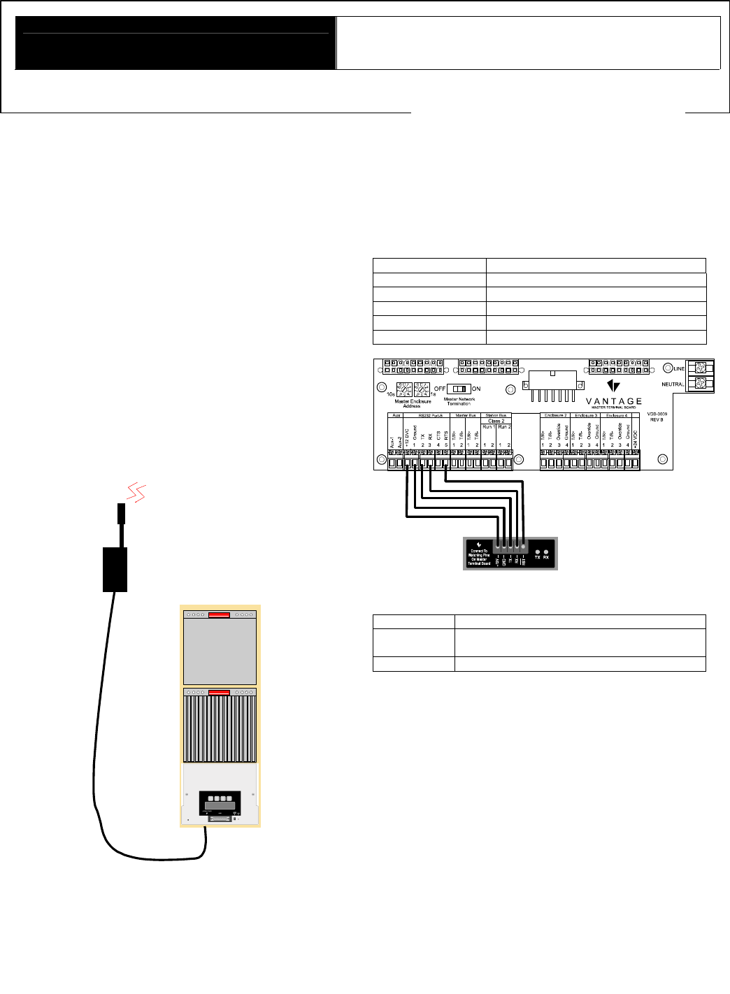
Connections
Connections to the Enabler are all made to the 5-position
removable screw terminal. The chart and figure below show how
the connections from the Master Power Enclosure to the Enabler
are made.
RF Enabler Connection
+12V Master Power Enclosure +12V
GND Master Power Enclosure GND
TX Master Power Enclosure TX
RX Master Power Enclosure RX
/RST Master Power Enclosure RTS
Indicators
LED Function
TX Indicates the RF Enabler is transmitting
data.
RX Indicates the RF Enabler is receiving data.
Setup
When the connections have been made as described above,
insert the Master Controller (MC) into the Master Power
Enclosure (MPE).
Using the RadioPoint Enabler
The Enabler is used to enable the Master Controller to
communicate by wireless link with Vantage RF products. Once
the Enabler is installed, Q-Link can be used to configure
Vantage RF Products as they are installed on the network.
Trouble shooting
−− Double check wiring using the chart to the left.
−− Is the Master Controller in place in the Master Power
Enclosure?
−− Make sure the Master Controller is not addressed to 0.

2
Radio Specifications
FCC ID# ............................................................. PII-RFE1000
Frequency Range .............................. 902-928 MHz ISM Band
Power Supply.............................................................. 12 VDC
Current required while transmitting................................180mA
Current required while receiving..................................... 70mA
Antenna Connection
.................................Permanent (Solder)
Antenna Gain
...................................................................2dBi
Transmit Power ...........................................................140mW
RF Technology ............ Frequency Hopping Spread Spectrum
Number of Hop Channels.....................................................25
RF Data Rate ........................................................ 19,200 bps
Interface Data Rate ............................................... 19,200 bps
Operating Temperature Range.................................. -40-70°C
FCC ID: PII-RFE1000
This device complies with Part 15 of the FCC Rules. Operation is
subject to the following two conditions: (1) This device may not
cause harmful interference, and (2) this device must accept any
interference received, including interference that may cause
undesired operation.
NOTE: This equipment has been tested and found to comply with
the limits for a Class B digital device, pursuant to Part 15 of the
FCC Rules. These limits are designed to provide reasonable
protection against harmful interference in a residential installation.
This equipment generates, uses and can radiate radio frequency
energy and, if not installed and used in accordance with the
instructions, may cause harmful interference to radio
communications. However, there is no guarantee that interference
will not occur in a particular installation. If this equipment does
cause harmful interference to radio or television reception, which
can be determined by turning the equipment off and on, the user is
encouraged to try to correct the interference by one or more of the
following measures:
-- Reorient or relocate the receiving antenna.
-- Increase the separation between the equipment and receiver.
-- Connect the equipment into an outlet on a circuit different from
that to which the receiver is connected.
-- Consult the dealer or an experienced radio/TV technician for
help.
Changes or modifications to this product not expressly approved by
Vantage Controls could void the user’s authority to operate this
product.