Varex Imaging Deutschland XRPAD2 802.11n 3T3R Mini PCIe Module User Manual
PerkinElmer Medical Imaging 802.11n 3T3R Mini PCIe Module Users Manual
Contents
- 1. User manual
- 2. Users Manual
Users Manual
DIGITAL IMAGING
68153 01
XRpad2 4336 Digital X-ray
Detector System User Manual
Before using the X-ray detector, be sure to read this manual thoroughly along with any
other manuals for the software and other system components. Keep this manual where it
is easily accessible.

DIGITAL IMAGING
ii www.perkinelmer.com 68153 01
Before You Begin XRpad2 4336
Before You Begin
•To avoid personal injury or product damage, read the manual and all accompanying
information carefully before installing and using the X-ray detector.
•The X-ray detector is intended for use by trained and qualified professional personnel who
are knowledgeable with the use of X-ray detectors, X-ray systems, and electrical equipment.
•The user is responsible for using and maintaining the detector according to prescribed
installation, usage, maintenance, handling, and storage specifications. To keep the detector
and its accessories in a safe and proper condition, only trained and qualified professional
person(s) shall be in charge of maintenance.
•X-ray imaging, image processing, image acquisition, and data storage must be performed in
accordance with the applicable laws. The user is also responsible for compliance to laws
pertaining to the privacy of image data.
•In no event is X-ray detector manufacturer liable for direct, indirect, or consequential injury,
damage, or loss of equipment operation time or image data arising from the use of the X-ray
detector, its components, and/or accessories.
Protection Against Ionizing Radiation
•Exposure of any part of the human body to X-radiation may be harmful to health. Whenever
X-ray equipment or radioactive sources are in use, appropriate safety precautions and
measures shall be instituted, and all regulatory requirements must be met. It is the
responsibility of the X-ray system installer, operator, and user to comply with applicable
requirements.
•The X-ray detector is intended to be installed, maintained, and used by qualified professional
personnel who are trained and qualified in the installation, maintenance, and use of X-ray
equipment.
•The X-ray detector does not contain a primary barrier for X-rays or Gamma rays. The X-ray
system installer or X-ray system manufacturer must provide the necessary protection based
on the X-ray system’s intended use.
•For portable applications, the X-ray system installer or X-ray system manufacturer must
provide the necessary training for operators to protect themselves, patients, and surrounding
persons.

DIGITAL IMAGING
68153 01 www.perkinelmer.com iii
XRpad2 4336 For Your Safety
For Your Safety
To avoid personal injury or product damage, read this manual and all accompanying informa-
tion carefully before handling, installing, or using the X-ray detector. Follow all instructions,
warnings, and cautions in this manual and all warnings and cautions printed on the warning
label. Ignoring instructions, warnings, or cautions in the handling, installing, or using of the
detector may result in personal injury, death, or product damage. Keep this manual for future
reference.
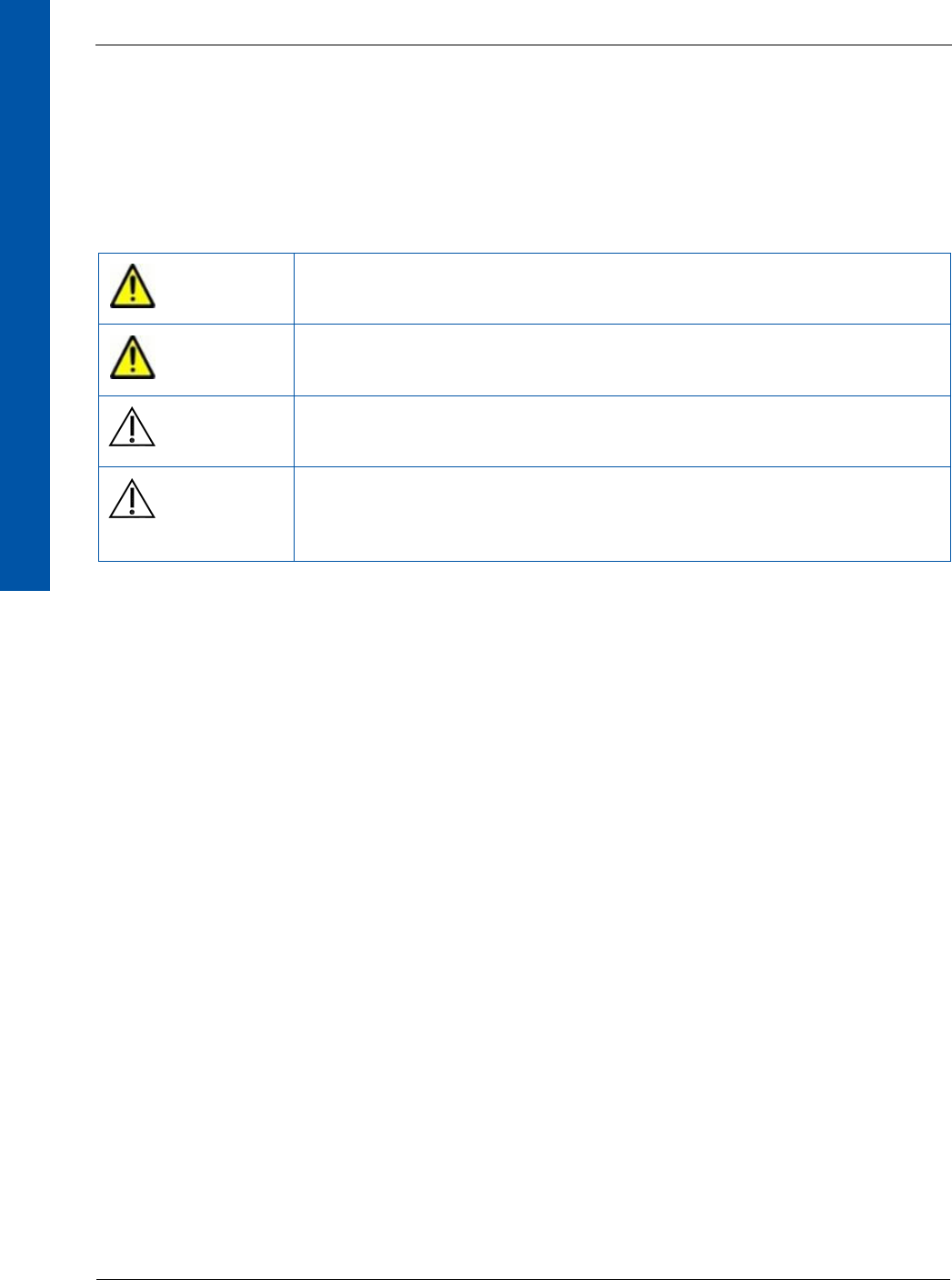
Meaning of Alerts and Notes
DANGER This indicates a potentially hazardous situation which, if ignored, will
result in severe personal injury, death, or substantial product damage.
WARNING This indicates a potentially hazardous situation which, if ignored, may
result in severe personal injury, death, or substantial product damage.
Caution This indicates a potential hazardous situation which, if ignored, may
result in minor or moderate personal injury or damage to the product.
Note This emphasizes or supplements important information about the
main text.
DIGITAL IMAGING
iv www.perkinelmer.com 68153 01
For Your Safety XRpad2 4336
Installation and Environment of Use
WARNING Do not operate the X-ray detector in or around flammable gases, gas mixtures,
liquids, chemicals, or other substances. Ignoring this warning may result in
explosion, fire, or electric shock, which may result in severe personal injury,
death, or substantial product damage.
Caution Do not operate the X-ray detector in a location with the following
conditions.
•Close to fluid or places where fluid is used
•Close to heat sources, such as a heater
•High temperature environment
•High humidity environment
•High condensation environment
•Extreme cold environment
•Dusty environment
•Salty or sulphurous environment
•Near a vibrating environment
Ignoring this caution may result in personal injury or damage to
the product.
WARNING Do not connect the X-ray detector to any component or accessory other
than the manufacturer’s specified components and accessories.
Ignoring this warning may result in explosion, fire, or electric shock,
which may result in severe personal injury, death, or substantial
product damage.
WARNING Do not modify or alter the X-ray detector, its components, or
accessories. Ignoring this warning may result in explosion, fire, or
electric shock, which may result in severe personal injury, death, or
substantial product damage.
WARNING The detector is not designed to control X-ray dose. The system
integrator is responsible for controlling the X-ray radiation.

DIGITAL IMAGING
68153 01 www.perkinelmer.com v
XRpad2 4336 For Your Safety
Interface and Power Unit and Cables
WARNING Be sure to turn OFF the power of the X-ray detector, including turning
off the power supply or removing the battery (if applicable) before
servicing, maintaining, connecting, or disconnecting the cables or
accessories.
Do not touch the power supply, Lithium Battery Pack, X-ray detector,
cable, connector, or any other electrical component or equipment with
wet hands. Ignoring this warning may cause electrical shock, which
may result in severe personal injury, death, or substantial product
damage.
WARNING Disconnect the cables by pulling on the connector and not the cable
itself. Ignoring this warning may cause electrical shock, which may
result in severe personal injury, death, or substantial product damage.
WARNING Do not modify the cables or subject the cable to external stress or
damage. Avoid placing anything heavy, including the detector, on the
cable, stepping on the cable, pulling the cable, or subjecting the cable
to excessive bending or bundling. Ignoring this warning may cause
cable failure resulting in electrical shock, which may result in severe
personal injury, death, or substantial product damage.
WARNING Do not turn ON the power supply or X-ray detector when
condensation is on the X-ray detector or any of its components or
accessories. Ignoring this warning may cause electrical shock, which
may result in severe personal injury, death, or substantial product
damage.
WARNING To avoid risk of electric shock, this equipment must only be connected
to a supply mains with protective earth.
DIGITAL IMAGING
vi www.perkinelmer.com 68153 01
For Your Safety XRpad2 4336
Handling
WARNING Never disassemble, modify, or alter the X-ray detector, its components,
Lithium Battery Pack battery, battery charger, or accessories. Ignoring
this warning may cause electrical shock and/or unknown hazards,
which may result in severe personal injury, death, or substantial
product damage.
WARNING Do not touch the interface and power unit or cable and the patient at
the same time. Do not let the patient touch the interface and power
unit or cable. Ignoring this warning may cause electrical shock and/or
unknown hazards, which may result in severe personal injury, death,
or substantial product damage.
Caution Place the X-ray detector horizontally on a flat, stable surface. If the
X-ray detector is placed vertically or in any tilted position, the X-ray
detector must be securely placed in the Bucky tray or securely fastened
to the X-ray detector enclosure or support structure. Ignoring this
caution may result in personal injury or damage to the product.
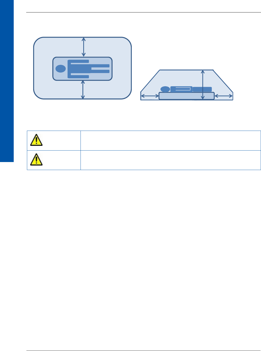
Caution Do not exceed the maximum uniform load weight of 150 kg
distributed across the surface of the X-ray detector.
Caution Do not exceed the maximum load weight of 100 kg distributed on an
area of 40 mm in a diameter of the X-ray detector surface.
Caution Do not drop the X-ray detector. If the X-ray detector is dropped,
remove the X-ray detector from service, and immediately ask your
establishment’s safety representative to verify or re-validate the
proper function of the X-ray detector prior to resuming use of the
detector. Further use under abnormal conditions may result in severe
personal injury, death, or substantial product damage.
DIGITAL IMAGING
68153 01 www.perkinelmer.com vii
XRpad2 4336 For Your Safety
Battery
WARNING Do not use the XRpad2 LBP (battery) if the casing is broken or if it
emits an unusual odor, smoke, or excessive heat, or if it leaks any
substance. Avoid contact with any substance seeping from the battery
pack. If any fluid touches your skin or eyes, wash the affected area
with clean, running water and immediately seek medical attention.
WARNING The cells within the battery contain toxic substances. Do not attempt
to open the battery. Do not insert any object into the battery pack or
use any device to pry at the battery pack casing. Attempting to open
the battery casing will damage the casing, which could cause the
battery to release toxic and harmful substances causing injuries such
as electric shock or burns, or cause a fire, and will render the pack
unusable.
WARNING Observe and follow all safety information in this manual and on the
warning label found on the battery. Ignoring a warning may result in
personal injury or damage to the product.
WARNING Use only charging devices approved by device manufacturer, and
never attempt to bypass or override their charging protection circuits.
WARNING Keep out of reach of children.
WARNING Remove the battery if the X-ray detector is not likely to be used for
some time.
WARNING Do not submerge the battery in water or other liquid.
WARNING Do not charge the battery near flammable materials.
WARNING Do not connect the battery to an electrical outlet directly, or to any
other electrical source not described in the manual.
DIGITAL IMAGING
viii www.perkinelmer.com 68153 01
For Your Safety XRpad2 4336
WLAN
WARNING Do not drop or hit the battery against hard objects since this may cause
damage to the battery and risk release of the battery toxic and harmful
substances, causing injuries such as electric shock or burns or causing
a fire, and will render the battery unusable.
WARNING Do not use the battery charger in the patient environment.
Caution There is a risk of explosion, personal injury, or damage to product if
the battery is replaced by non-OEM approved components.
WARNING Do not obstruct the detector antenna. If it is obstructed by metal,
wood, or a human body, the wireless communication can be slowed
down or disconnected.
WARNING Follow the laws and regulations for each country, and select the
regional code accordingly.
WARNING Do not use the detector in aircraft because there is a potential affect to
aviation systems.
Caution Use WLAN access point devices to get the best communication
performance.
Caution The electromagnetic emission of the detector may influence
implantable medical devices like pacemakers. Check the information
for these devices.
WARNING Do not modify or alter the detector as this can violate the certification
of the Radio Law.

DIGITAL IMAGING
68153 01 www.perkinelmer.com ix
XRpad2 4336 For Your Safety
Automatic Exposure Detection (AED) Mode
If a Problem Occurs
WARNING The AED mode requires a sufficient X-ray dose rate to the detector
surface. The required dose rate can vary between X-Ray tube,
generator, and X-ray voltage. The system integrator must evaluate the
AED operation with the complete X-ray setup in order to secure a
proper image acquisition in AED mode.
WARNING The external sync mode is the default acquisition mode, and the
detector needs to switch into the AED mode to use the Auto Exposure
detection. It is important that a settling time for the AED is
implemented by the system integrator. If the settling time is too short,
the image can show artifacts.
WARNING The AED on-time is limited and must be turned off directly after
acquiring the image. Staying longer in AED mode will reduce the
battery duty cycle and heat up the detector.
WARNING Do not apply any, handling, loading, mechanical shock, or electronic
noise to the detector while it is in AED mode. These actions can start
an unwanted acquisition (false trigger). If a false trigger is applied to
the detector, the detector will not be able to react on a real X-ray
exposure until it has acquired the false trigger image.
WARNING If any abnormal condition, such as smoke, fumes, or strange sounds,
is evident, turn off the X-ray detector, turn off and unplug the power
supply from the AC outlet, and immediately ask your establishment’s
safety representative to contact your dealer, distributor, or device
manufacturer.
Further use under abnormal conditions may result in severe personal
injury, death, or substantial product damage.
WARNING When liquid has been spilled into or on any part of the X-ray detector
or power supply (if applicable), or when the X-ray detector, its
component, or accessory is dropped, unplug the power supply from
the AC outlet, and immediately ask your establishment’s safety
representative to contact your dealer, distributor, or device
manufacturer.
Further use under abnormal conditions may result in severe personal
injury, death, or substantial product damage.
DIGITAL IMAGING
x www.perkinelmer.com 68153 01
For Your Safety XRpad2 4336
Maintenance and Inspection
WARNING Turn off the power of the X-ray detector when the inspections
indicated in this manual are going to be performed. Ignoring this
warning may result in electric shock, which may result in severe
personal injury, death, or substantial product damage.
WARNING When the X-ray detector system is going to be cleaned, turn off the
X-ray detector and remove the battery. If the X-ray detector is
connected to a power supply, turn off the power switch and/or unplug
the power supply cable from the AC outlet. If the X-ray detector is
battery powered, remove the battery. Never use thinner, benzine,
acetone, or other flammable cleaning agents. Ignoring this warning
may result in explosion, fire, or electric shock, which may result in
severe personal injury, death, or substantial product damage.
WARNING The X-ray detector must be repaired by X-ray detector manufacturer-
authorized personnel only. Ignoring this warning may result in
explosion, fire, electric shock, or unknown hazards, which may result
in severe personal injury, death, or substantial product damage.
Caution Follow the manufacturer’s recommendations for inspecting the X-ray
detector before use.

DIGITAL IMAGING
68153 01 www.perkinelmer.com xi
Table of Contents
1.0 Scope . . . . . . . . . . . . . . . . . . . . . . . . . . . . . . . . . . . . . . . . . . . . . . . . . . . . . . . . . . . . . . . 1
2.0 Usage . . . . . . . . . . . . . . . . . . . . . . . . . . . . . . . . . . . . . . . . . . . . . . . . . . . . . . . . . . . . . . . 1
3.0 Audience. . . . . . . . . . . . . . . . . . . . . . . . . . . . . . . . . . . . . . . . . . . . . . . . . . . . . . . . . . . . . 1
4.0 Abbreviations . . . . . . . . . . . . . . . . . . . . . . . . . . . . . . . . . . . . . . . . . . . . . . . . . . . . . . . . . 2
5.0 References . . . . . . . . . . . . . . . . . . . . . . . . . . . . . . . . . . . . . . . . . . . . . . . . . . . . . . . . . . . 3
6.0 Definition of Symbols . . . . . . . . . . . . . . . . . . . . . . . . . . . . . . . . . . . . . . . . . . . . . . . . . . 3
7.0 Standards and Regulations . . . . . . . . . . . . . . . . . . . . . . . . . . . . . . . . . . . . . . . . . . . . . 5
8.0 Description of the X-ray Detector. . . . . . . . . . . . . . . . . . . . . . . . . . . . . . . . . . . . . . . . . 6
8.1 Overview of the X-ray Detector. . . . . . . . . . . . . . . . . . . . . . . . . . . . . . . . . . . . . . . . . . . 6
8.2 Environmental Considerations . . . . . . . . . . . . . . . . . . . . . . . . . . . . . . . . . . . . . . . . . . . 8
8.3 X-ray Detector Specification. . . . . . . . . . . . . . . . . . . . . . . . . . . . . . . . . . . . . . . . . . . . . . 9
8.4 X-ray Detector Dimensions. . . . . . . . . . . . . . . . . . . . . . . . . . . . . . . . . . . . . . . . . . . . . . 10
8.5 X-ray Detector Accessories . . . . . . . . . . . . . . . . . . . . . . . . . . . . . . . . . . . . . . . . . . . . . . 11
8.5.1 Rechargeable Lithium Battery Pack (XRpad2 LBP) . . . . . . . . . . . . . . . . . 13
8.5.2 XRpad IPU-2. . . . . . . . . . . . . . . . . . . . . . . . . . . . . . . . . . . . . . . . . . . . . . . . . . 18
8.6 Minimum System Requirements . . . . . . . . . . . . . . . . . . . . . . . . . . . . . . . . . . . . . . . . . 21
8.7 Operating the X-ray Detector. . . . . . . . . . . . . . . . . . . . . . . . . . . . . . . . . . . . . . . . . . . . 22
8.7.1 Wired X-ray Detector Connection. . . . . . . . . . . . . . . . . . . . . . . . . . . . . . . . 23
8.7.2 Wireless X-ray Detector Connection. . . . . . . . . . . . . . . . . . . . . . . . . . . . . . 24
8.7.3 Before Using the X-ray Detector . . . . . . . . . . . . . . . . . . . . . . . . . . . . . . . . . 25
8.7.4 Powering On the X-ray Detector. . . . . . . . . . . . . . . . . . . . . . . . . . . . . . . . . 26
8.7.5 Powering Off the X-ray Detector. . . . . . . . . . . . . . . . . . . . . . . . . . . . . . . . . 27
8.7.6 General Workflow for Acquiring an Image. . . . . . . . . . . . . . . . . . . . . . . . 27
9.0 Inspection and Maintenance. . . . . . . . . . . . . . . . . . . . . . . . . . . . . . . . . . . . . . . . . . . . 29
9.1 Daily Inspection . . . . . . . . . . . . . . . . . . . . . . . . . . . . . . . . . . . . . . . . . . . . . . . . . . . . . . . 29
9.1.1 Before Turning On the Power . . . . . . . . . . . . . . . . . . . . . . . . . . . . . . . . . . . 29
9.1.2 After Turning On the Power . . . . . . . . . . . . . . . . . . . . . . . . . . . . . . . . . . . . 31
9.1.3 After Turning Off the Power . . . . . . . . . . . . . . . . . . . . . . . . . . . . . . . . . . . . 31
9.2 Monthly Inspection . . . . . . . . . . . . . . . . . . . . . . . . . . . . . . . . . . . . . . . . . . . . . . . . . . . . 32
9.3 Yearly Inspection . . . . . . . . . . . . . . . . . . . . . . . . . . . . . . . . . . . . . . . . . . . . . . . . . . . . . . 32
9.4 Calibrating the X-ray Detector . . . . . . . . . . . . . . . . . . . . . . . . . . . . . . . . . . . . . . . . . . . 33

DIGITAL IMAGING
xii www.perkinelmer.com 68153 01
Table of Contents XRpad2 4336
9.5 Cleaning the X-ray Detector . . . . . . . . . . . . . . . . . . . . . . . . . . . . . . . . . . . . . . . . . . . . 33
9.6 Error Messages and Troubleshooting . . . . . . . . . . . . . . . . . . . . . . . . . . . . . . . . . . . . 34
10.0 After-Sales Service for PerkinElmer Products . . . . . . . . . . . . . . . . . . . . . . . . . . . . . 34
11.0 Disposing of the X-ray Detector . . . . . . . . . . . . . . . . . . . . . . . . . . . . . . . . . . . . . . . . . 35
12.0 Declarations . . . . . . . . . . . . . . . . . . . . . . . . . . . . . . . . . . . . . . . . . . . . . . . . . . . . . . . . . 36
12.1 Guidance and Manufacturer’s Declaration . . . . . . . . . . . . . . . . . . . . . . . . . . . . . . . . 36
12.2 Declaration of Conformity for European Union (and EEA) . . . . . . . . . . . . . . . . . . 40
12.3 Federal Communication Commission Interference Statement (US) . . . . . . . . . . . 42
12.4 Industry Canada Statement (English) . . . . . . . . . . . . . . . . . . . . . . . . . . . . . . . . . . . . 43
12.5 Industrie Canada – Déclaration (Français) . . . . . . . . . . . . . . . . . . . . . . . . . . . . . . . . 44
12.6 Korean. . . . . . . . . . . . . . . . . . . . . . . . . . . . . . . . . . . . . . . . . . . . . . . . . . . . . . . . . . . . . . . 45

DIGITAL IMAGING
68153 01 www.perkinelmer.com xiii
List of Figures
Figure 1 X-ray Detector (Front View) . . . . . . . . . . . . . . . . . . . . . . . . . . . . . . . . . . . . . . . . . . . . . . 6
Figure 2 Dimensions for the X-ray Detector . . . . . . . . . . . . . . . . . . . . . . . . . . . . . . . . . . . . . . . 10
Figure 3 Patient Vicinity . . . . . . . . . . . . . . . . . . . . . . . . . . . . . . . . . . . . . . . . . . . . . . . . . . . . . . . . 12
Figure 4 XRpad2 LBP . . . . . . . . . . . . . . . . . . . . . . . . . . . . . . . . . . . . . . . . . . . . . . . . . . . . . . . . . . 13
Figure 5 Removing the XRpad2 LBP. . . . . . . . . . . . . . . . . . . . . . . . . . . . . . . . . . . . . . . . . . . . . . 16
Figure 6 XRpad IPU-2 . . . . . . . . . . . . . . . . . . . . . . . . . . . . . . . . . . . . . . . . . . . . . . . . . . . . . . . . . . 18
Figure 7 Wired Connection of the X-ray Detector. . . . . . . . . . . . . . . . . . . . . . . . . . . . . . . . . . . 23
Figure 8 Wireless Connection of the X-ray Detector (Station/Client Mode) . . . . . . . . . . . . 24
Figure 9 Wireless Connection of the X-ray Detector (WAP Mode) . . . . . . . . . . . . . . . . . . . . 25
Figure 10 Workflow for Acquiring an Image . . . . . . . . . . . . . . . . . . . . . . . . . . . . . . . . . . . . . . . 28


DIGITAL IMAGING
68153 01 www.perkinelmer.com xv
List of Tables
Table 1 Abbreviations . . . . . . . . . . . . . . . . . . . . . . . . . . . . . . . . . . . . . . . . . . . . . . . . . . . . . . . . . . 2
Table 2 References . . . . . . . . . . . . . . . . . . . . . . . . . . . . . . . . . . . . . . . . . . . . . . . . . . . . . . . . . . . . . 3
Table 3 Symbols . . . . . . . . . . . . . . . . . . . . . . . . . . . . . . . . . . . . . . . . . . . . . . . . . . . . . . . . . . . . . . . 3
Table 4 Standards and Regulations . . . . . . . . . . . . . . . . . . . . . . . . . . . . . . . . . . . . . . . . . . . . . . . 5
Table 5 Overview of the X-ray Detector . . . . . . . . . . . . . . . . . . . . . . . . . . . . . . . . . . . . . . . . . . . 6
Table 6 Environmental Considerations. . . . . . . . . . . . . . . . . . . . . . . . . . . . . . . . . . . . . . . . . . . . 8
Table 7 X-ray Detector Specification . . . . . . . . . . . . . . . . . . . . . . . . . . . . . . . . . . . . . . . . . . . . . . 9
Table 8 Accessories for the X-ray Detector. . . . . . . . . . . . . . . . . . . . . . . . . . . . . . . . . . . . . . . . 11
Table 9 Specification of the XRpad2 LBP . . . . . . . . . . . . . . . . . . . . . . . . . . . . . . . . . . . . . . . . . 14
Table 10 Overview of the XRpad IPU-2 . . . . . . . . . . . . . . . . . . . . . . . . . . . . . . . . . . . . . . . . . . . 19
Table 11 Specification of the XRpad IPU-2. . . . . . . . . . . . . . . . . . . . . . . . . . . . . . . . . . . . . . . . . 20
Table 12 Guidance and Manufacturer’s Declaration of Electromagnetic Emissions . . . . . . 36
Table 13 Guidance and Manufacturer’s Declaration of Electromagnetic Immunity . . . . . . 37
Table 14 Recommended Separation Distance between Portable and Mobile
RF-Communication Equipment and the X-ray Detector . . . . . . . . . . . . . . . . . . . . . 38
Table 15 Guidance and Manufacturer’s Declaration of Electromagnetic Immunity
(Portable Equipment). . . . . . . . . . . . . . . . . . . . . . . . . . . . . . . . . . . . . . . . . . . . . . . . . . . 39


68153 01 www.perkinelmer.com 1
DIGITAL IMAGING
1.0 Scope
This document describes design elements and respective interfaces for the XRpad2 4336 detector.
Applicable mechanical, electronic, and software interfaces are addressed. PerkinElmer digital
X-ray Flat Panel Detectors and their accessories are components designed to be integrated into
products by X-ray system manufacturers. Manufacturers are responsible for qualifying, validat-
ing, and certifying their products for their intended uses and meeting all applicable regulatory
requirements.
Final application and intended use is based on the completed X-ray system design. It is the
responsibility of the X-ray system manufacturer to confirm the efficacy and compliance of the
X-ray system for its intended use, inclusive of the detector. The Digital Radiography Software
referred to in this manual is medical imaging software for radiography, which is typically
supplied by the X-ray system manufacturer or third-party provider and is not part of the
XRpad2 4336 detector.
2.0 Usage
The XRpad2 4336 detector is a component of a digital imaging system used for generating
radiographic images of human anatomy for diagnostic X-ray procedures, wherever conventional
Screen-Film (SF), Digital Radiography (DR), or Computed Radiography (CR) systems may
be used.
3.0 Audience
This document is for users of the X-ray detector and for X-ray system manufacturers and X-ray
system installers who are responsible for installing the X-ray detector into an X-ray system.

XRpad2 4336
268153 01
DIGITAL IMAGING
4.0 Abbreviations
Table 1 includes a list of abbreviations used in this manual and a description of each
abbreviation.
Table 1 Abbreviations
Abbreviation Description
AED Automatic Exposure Detection
AP Access Point
CR Computed Radiography
DFS Dynamic Frequency Selection
DR Digital Radiography
ESS Extended Service Set
FoV Field of View
fps Frames per second
GigE Gigabit Ethernet
I/F Interface
IP Internet Protocol
IPU Interface and Power Unit
LAN Local Area Network
LBC Lithium Battery Charger
LBP Lithium Battery Pack
LED Light Emitting Diode
MDD Medical Device Directive
OEM Original Equipment Manufacturer
REF Radiated Electromagnetic Field
Rx Caution: Federal law restricts this device to sale by or on the order of a licensed
healthcare practitioner
SELV Separated or Safety Extra-Low Voltage
SF Screen Film
WAP Wireless Access Point
WEEE Waste Electrical and Electronic Equipment
Wi-Fi Wireless Fidelity
WLAN Wireless Local Area Network

68153 01 www.perkinelmer.com 3
XRpad2 4336
DIGITAL IMAGING
5.0 References
Table 2 includes a list of documents referred to in this manual. For access to the following
references, contact your establishment’s representative or your dealer, distributor, or device
manufacturer.
6.0 Definition of Symbols
Table 3 includes a list of symbols and a description of each symbol.
Table 2 References
Document Name Document #
1XRpad LBC Charger for Rechargeable Lithium-Ion
Battery Pack
48773
2XRpad LBP Rechargeable Lithium-Ion Battery
Pack
48772
3XRpad2 4336 Digital X-ray Detector System
Reference Manual
69652
4Digital Radiography Software Manual Supplied by X-ray system manufacturer or
third-party provider
5 Digital Radiography Software Supplied by X-ray system manufacturer or
third-party provider
6Access Point Manual Supplied by the Access Point Manufacturer or
third-party provider
Table 3 Symbols
Symbol Description
This Way Up.
Handle with Care.
pKeep Dry.
Reusable.
Disposal (WEEE).
Follow all local and regional disposal requirements.
Refer to instruction manual/booklet.
MManufacturer‘s name and address.
NDate of Manufacture, YYYY-MM, YYYY=Year, MM=Month.
hREF = Reference Number.
PerkinElmer Catalog Number, Part Number, or Material Number.

XRpad2 4336
468153 01
DIGITAL IMAGING
Symbol Description
fSerial Number.
~AC Input.
D.C. Voltage.
Temperature Limitation.
Relative Humidity Limitation.
Potential Equalization.
Functional Earth Connection.
Protection Class I.
Protection Class II.
Non-Ionizing Radiation.
Battery charge condition.
•Battery Charged (> 75%).
•Battery ¾ (≤75%).
•Battery Half (≤50%).
•Battery Low (≤25%).
•Battery Empty (≤10%).
•No Battery.
/ Wireless Connectivity/No Wireless Connectivity.
/ LAN Connection/Missing LAN Connection.
Access Point
Trigger Connection.
Push Button.
Power Switch.
Do not crush.
Do not expose to fire.
Table 3 Symbols (Continued)

68153 01 www.perkinelmer.com 5
XRpad2 4336
DIGITAL IMAGING
7.0 Standards and Regulations
The X-ray detector is designed to be compliant with the standards and/or regulations detailed in
Table 4. The manufacturer’s certifications to standards and regulations are valid only if the
original accessories (as listed in Table 8) are used according to prescribed instructions. Product
certification and warranty are rendered void if any modification or alteration to the product is
made, or any instruction, warning, or caution is not followed.
Symbol Description
Keep away from children.
Maximum Load.
UL Recognized component mark for US and Canada.
European Conformity markings for the product.
Table 4 Standards and Regulations
Standards and Regulations Description
ANSI/AAMI Std ES60601-1:2005 Medical electrical equipment Part 1: General Requirements for
Basic Safety and Essential Performance
EN IEC 60601-1:2006/AC:2010 General Requirements for Basic Safety for Medical Electrical
Equipment
EN IEC 60601-1-2:2007 Medical Electrical Equipment, Part 1-2: General Requirements for
Safety and Essential Performance – Collateral Standard:
Electromagnetic Compatibility
CAN CSA C22.2 No 60601-1 08 Medical Electrical Equipment Part 1: General Requirements for
Basic Safety and Essential Performance
FCC Part 15 subpart B/E Radio Frequency Exposure
ETSI EN 301 893 V.1.7.1 (2012) Broadband Radio Access Networks (BRAN); 5 GHz high
performance RLAN
ETSI EN 301 489-1 V1.9.2 (2011) Electromagnetic Compatibility and Radio spectrum Matters
(ERM); Electromagnetic Compatibility (EMC) standard for radio
equipment and services; Part 1: Common technical requirements
ETSI EN 301 489-17 V2.2.1 (2012) Electromagnetic Compatibility and Radio spectrum Matters
(ERM); Electromagnetic Compatibility (EMC) standard for radio
equipment and services; Part 17: Specific conditions for 2.4 GHz
wideband transmission systems and 5 GHz high performance
RLAN equipment”
EN ISO 10993-5:2009 Biological evaluation of medical devices – Part 5: Tests for
in vitro cytotoxicity
Table 3 Symbols (Continued)
XRpad2 4336
668153 01
DIGITAL IMAGING
8.0 Description of the X-ray Detector
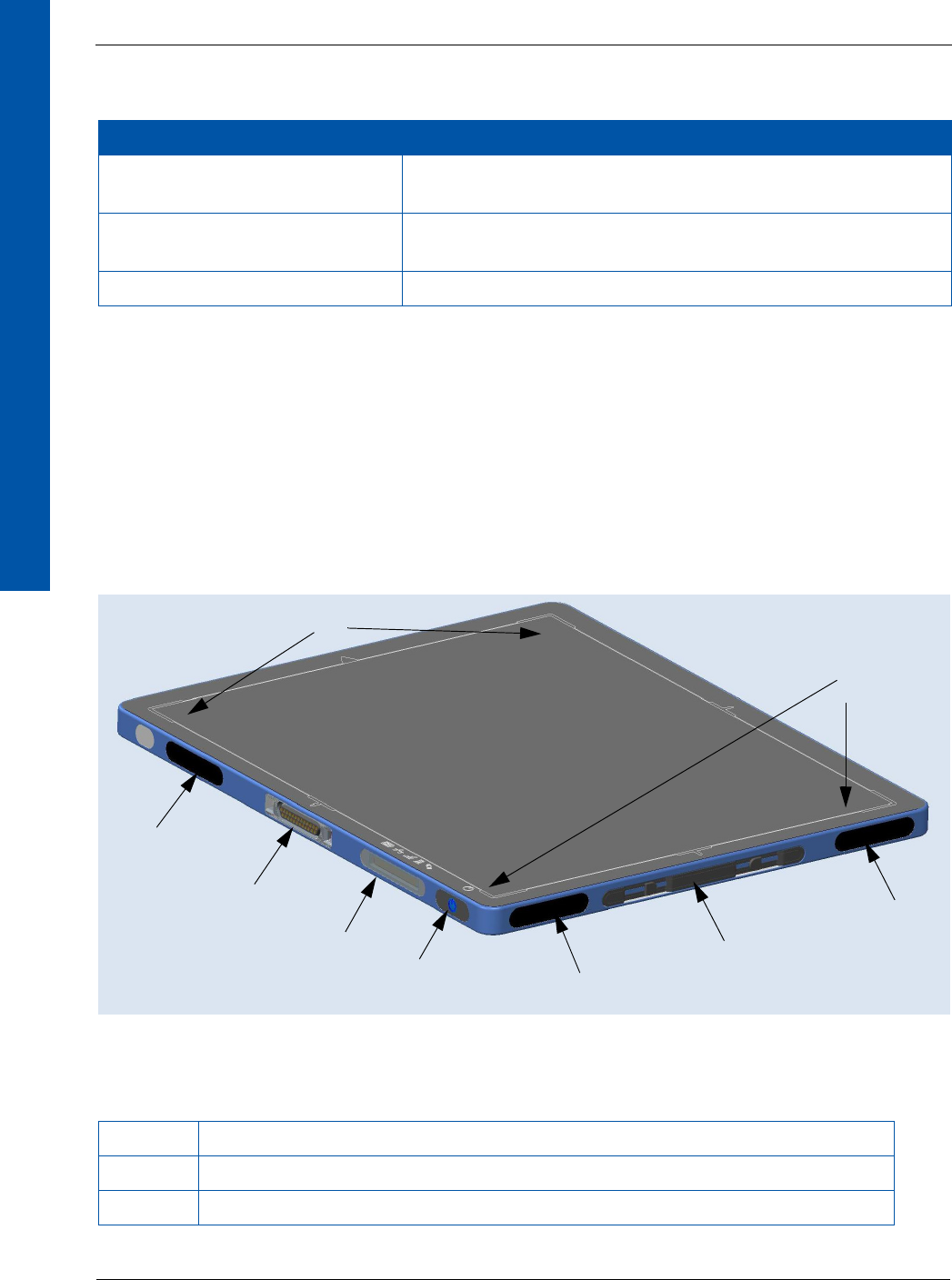
8.1 Overview of the X-ray Detector
The XRpad2 4336 is a wireless, light weight, cassette-sized flat panel detector for digital
radiography. It fits into a conventional table or wall-stand Bucky, just like a film-screen cassette.
Figure 1 shows the front view of the X-ray detector, and Table 5 includes a brief description of
each feature.
Figure 1 X-ray Detector (Front View)
Standards and Regulations Description
EN ISO 10993-10-2010-2013 Biological evaluation of medical devices – Part 10: Tests for
irritation and skin sensitization
EN ISO 4090:2004 Photography – Medical Radiographic Cassettes/Screens/Films
and Hard-Copy Imaging Films – Dimensions and Specifications
EN 60529:1991 + A1:2000 Degrees of Protection Provided by Enclosures (IP-code)
Table 5 Overview of the X-ray Detector
1 Active Area with Markers: 1a) Top and 1b) Bottom Side of the Image
2 Antenna. Make sure that they are not obstructed
3 Power and communication tethered connector
Table 4 Standards and Regulations (Continued)
1a
2
3
4
52
6
2
1b

68153 01 www.perkinelmer.com 7
XRpad2 4336
DIGITAL IMAGING
4Display
Battery charge condition
•Battery Charged (> 75%)
•Battery ¾ (≤75%)
•Battery Half (≤50%)
•Battery Low (≤25%)
•Battery Empty (≤10%)
•No Battery
Wireless Connectivity/No Wireless Connectivity /
Access Point
LAN Connection/No LAN Connection /
5 Push Button with a LED ☼ (blue light)
Short press and LED OFF Power ON and LED flashes
Short press and LED ON or flashes Switch On of the display
Long Press (4s) and LED ON or flashes Power OFF
LED Status (blue light)
LED OFF Detector is not powered
LED flashing (first instance) Detector is initializing
LED flashing (second instance) Detector is Ready
LED ON Detector is not connected to the
software
6 Battery Insert
Table 5 Overview of the X-ray Detector (Continued)

XRpad2 4336
868153 01
DIGITAL IMAGING
8.2 Environmental Considerations
Table 6 includes a list of environmental considerations for the transport, storage, and operation
of the X-ray detector.
WARNING Storage or use of the X-ray detector and power supply in
environmental conditions outside the specification may cause fire,
electrical shock, and unknown hazards, which may result in severe
personal injury, death, or substantial product damage or reduced
product lifetime.
Table 6 Environmental Considerations
Environment Transportation/Storagea
a. In original transport container for 365 days.
Operation
Ambient Temperatureb (30d/365d)
b. Temp. Gradient: max 4.5 K/hour.
–10°C to 55°C/0°C to 55°C 10°C to 35°C
Relative Humidity 5% to 90% 10% to 85%
Atmospheric Pressure 520 hPa to 1070 hPa 690 hPa to 1070 hPa
Vibrationc (EN60068-2-64)
c. Image quality cannot be guaranteed during shock or vibrations.
5 m2/s3 (10 Hz to 100 Hz)
1 m2/s3 (100 Hz to 2000 Hz)
0.5 m2/s3 (10 Hz to 100 Hz)
0.1 m2/s3 (100 Hz to 2000 Hz)
Shockc (EN 60068-2-27) 25 g (duration 6 ms) 2 g (duration 6 ms)
Ingress protection rating IPx4 rated (protection against splashing water)

68153 01 www.perkinelmer.com 9
XRpad2 4336
DIGITAL IMAGING
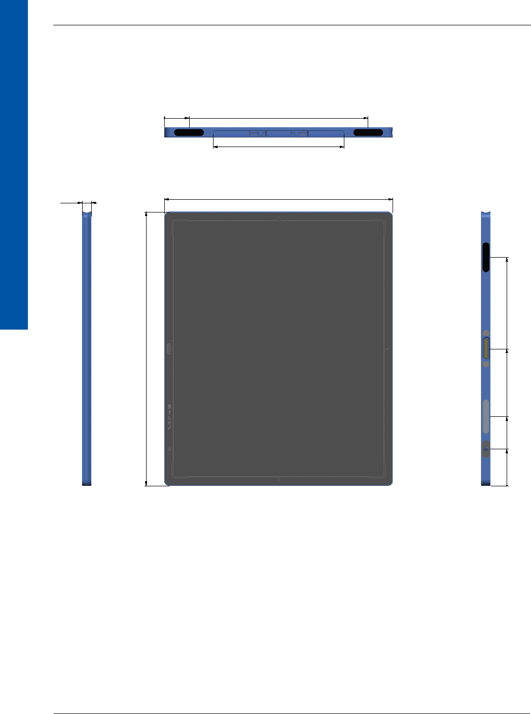
8.3 X-ray Detector Specification
Table 7 includes the specification for the X-ray detector.
Table 7 X-ray Detector Specification
Sensor
Panel Single substrate amorphous silicon active TFT/diode array
Scintillator Direct deposition CsI:Tl
Pixel Matrix 3524 x 4288
Pixel Pitch 100 μm
Electronics
Amplifiers Low noise ASICs with user selectable gains
ADC 16-bit
Image Transfer Time Wired: 500 ms; Wireless: 3000 ms
On-board Memory 1 GB DDR3, 4 GB SDHC card
Mechanical
Size ISO 4090 for 35 cm × 43 cm (14” × 17”) cassette size
Active Area 352.4mm x 428.8 mm
External Dimensions 384 mm (w) × 460 mm (l) × 15 mm (h)
Weight 3.1 kg
Housing Aluminum frame with carbon-fiber entrance window
Communication
Status Display OLED display with Wi-Fi, LAN, battery, and sensor indicators
Wireless Data I/F 802.11n Wi-Fi standard @ 5 GHz
Channel: WAP: 36-48, 149-165
Stationary: 36-48, 149-165
Stationary DFS:a52-64, 100-116, 132-140
a. Country-dependent.
Wired Data I/F GigE via optional power and communication tether
X-ray I/F Integrated X-ray trigger control
Automatic Exposure Detection
Image Performance
Limiting Resolution 5 cy/mm
Typical MTF 70% (1 cy/mm), 40% (2 cy/mm), 15% (4 cy/mm) for RQA5
Typical DQE 75% (0 cy/mm), 60% (1 cy/mm), 40% (3 cy/mm) for RQA5

68153 01 www.perkinelmer.com 11
XRpad2 4336
DIGITAL IMAGING
8.5 X-ray Detector Accessories
The X-ray detector shall only be used with its approved OEM Lithium Battery Pack XRpad2 LBP,
cables, and connectors. Product certification and warranty are rendered void if any modification
or alteration to the product is made, or any instruction, warning, or caution is not followed. It is
important that the X-ray detector is not directly connected to the clinical network. Connection of
the X-ray detector directly with the clinical computer network may disturb the IT environment.
The imaging workstation and the Wi-Fi access point must comply with IEC 60601-1 and/or
IEC 60950-1, depending on the usage and application.
Table 8 includes a list of accessories for the X-ray detector.
Table 8 Accessories for the X-ray Detector
PerkinElmer Article No. Description
95510949H-01 XRpad2 LBP (Lithium Battery Pack)
95510921H XRpad LBC (Lithium Battery Charger)
95510928H XRpad IPU-2 (Interface Power Unit)
95510970H XRpad2 LPT Detector Cable
95510590H XRpad2 Protective Insert
95510246H AC Cable IEC 60320 C13 DE
95510249H AC Cable IEC 60320 C13 US
95510256H Trigger Cable 5 m/16.5 ft
95510257H Trigger Cable 20 m/65.5 ft
95510621H XRD GigE Interface Cable 7.6 m/25 ft
95510622H XRD GigE Interface Cable 15.25 m/50 ft
95510623H XRD GigE Interface Cable 30.5 m/100 ft
XRpad2 4336
12 68153 01
DIGITAL IMAGING
Do not use any non-medical equipment in the patient vicinity, as shown in Figure 3.
Figure 3 Patient Vicinity
WARNING Connection of the X-ray detector directly to the clinical computer
network may disturb the IT environment.
WARNING Do not use any non-medical equipment, such as the Battery Charger or
Wi-Fi access point, in the patient environment.
1.5m
1.5m
2.5m
1.5m
1.5m
68153 01 www.perkinelmer.com 13
XRpad2 4336
DIGITAL IMAGING
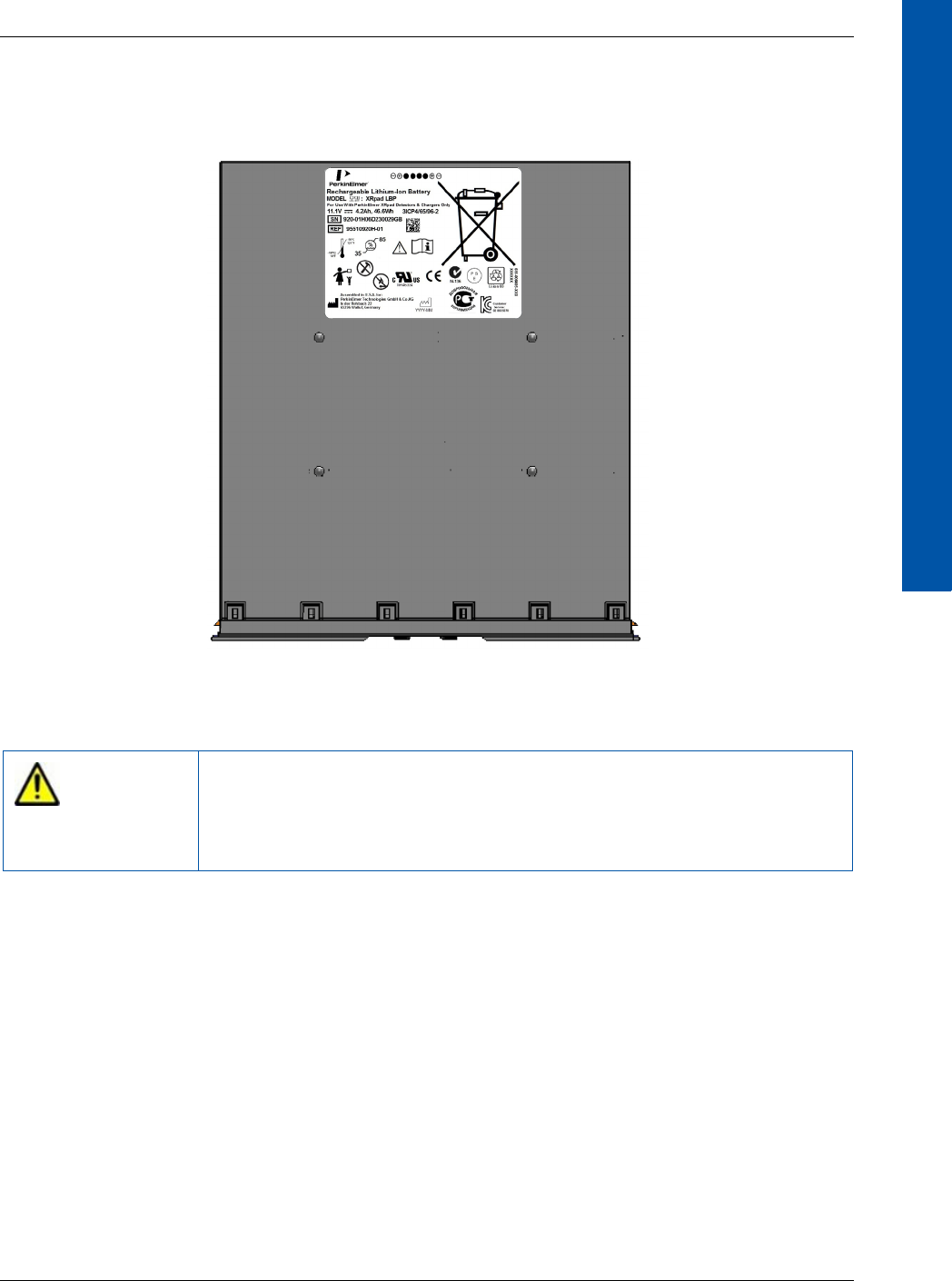
8.5.1 Rechargeable Lithium Battery Pack (XRpad2 LBP)
Figure 4 shows the XRpad2 LBP.
Figure 4 XRpad2 LBP
WARNING Storage or use of the Lithium Battery Pack environmental conditions
outside the specification may cause fire, electrical shock, and
unknown hazards, which may result in severe personal injury, death,
or substantial product damage or reduced product lifetime.

XRpad2 4336
14 68153 01
DIGITAL IMAGING
Table 9 includes the specification for the XRpad2 LBP.
8.5.1.1 Charging the XRpad2 LBP
•A new rechargeable Lithium Battery Pack (XRpad2 LBP) comes in a discharged condition
and must be charged using the dedicated lithium battery charger (XRpad LBC) before use.
Refer to the XRpad LBC manual for more details.
•The XRpad LBC will charge the XRpad2 LBP to a usable condition within three hours
depending on the initial state of charge. The X-ray a detector, when connected to the XRpad
Interface and Power Unit (XRpad IPU-2), can also charge the XRpad2 LBP, but the charge
rate is much slower.
•A charged battery will eventually lose its charge if unused. Upon initial use (or after a
prolonged storage period), the battery may require three to four charge/discharge cycles
before achieving maximum capacity.
•The actual battery run-time will depend on the power demands made by the X-ray detector.
•The XRpad2 LBP is keyed and can only be inserted into the XRpad LBC charger in one
orientation.
Table 9 Specification of the XRpad2 LBP
General
REF 95510949H-01
Voltage 11.1V
Amp-hours 4.2Ah
Capacity 46.6Wh
Charging Time Within 3 hours
Environmental
Relative Humidity 35% to ~85%
Operating (discharging) -10°C to 55°C
Charging 0°C to 42°C
Transportation -20°C to 45°C
Storage (up to 3 months) 15°C to 35°C
Ingress
Ingress Protection Rating IP54
Lifetime
Charge-discharge Cycles 500 cycles on average under normal usage conditions.
Battery should be discarded on or before five years from
date of manufacture indicated on the battery label.

68153 01 www.perkinelmer.com 15
XRpad2 4336
DIGITAL IMAGING
•Check to ensure the XRpad2 LBP is clean, dry, and free of foreign contamination or debris. If
cleaning is necessary, see “Section 8.5.1.6, Cleaning the XRpad2 LBP” on page 17 for cleaning
instructions.
•Ensure the XRpad LBC charger is powered on.
•Orient the XRpad2 LBP to match the orientation of the XRpad LBC Charger, and insert the
XRpad2 LBP firmly into the XRpad LBC charger. Keep the XRpad LBP in the XRpad LBC
charger until all the four charge status LEDs maintains a solid green, indicating a full charge.
To remove, lift the battery out of the XRpad LBC charger.
8.5.1.2 Installing the XRpad2 LBP
When installing the XRpad2 LBP in the X-ray detector in place of the XRpad2 Protective Insert,
or to change a used XRpad2 LBP, remove the XRpad Protective Insert or used XRpad2 LBP
before installing the new XRpad2 LBP (see “Section 8.5.1.3, Removing the XRpad2 LBP” on
page 16).
To install the XRpad2 LBP:
1Fully support the X-ray detector to prevent it from dropping or slipping.
2Check to ensure the battery compartment of the X-ray detector is clean, dry, and free of
foreign contamination or debris. If cleaning is necessary, see “Section 8.5.1.6, Cleaning the
XRpad2 LBP” on page 17 for cleaning instructions.
3Check to ensure the XRpad2 LBP is clean, dry, and free of foreign contamination or debris. If
cleaning is necessary, refer to “Section 8.5.1.6, Cleaning the XRpad2 LBP” on page 17 for
cleaning instructions.
4The XRpad2 LBP is keyed and can only be inserted into the XRpad2 4336 detector in one ori-
entation. Align the orientation of the XRpad2 LBP to match the orientation required on the X-
ray detector.
5Insert the charged XRpad2 LBP into the X-ray detector in the corresponding orientation, and
gently press on the end cap until the latches secure the XRpad2 LBP inside the detector.
WARNING Do not drop or hit the XRpad2 LBP against hard objects as this may
cause a risk of damage to the XRpad2 LBP, which may result in
exposure to the corrosive cell contents, fire, or explosion.
WARNING There is risk of explosion, personal injury, or damage to the product
if the Battery XRpad2 LBP is replaced by a non-OEM approved
component.
XRpad2 4336
16 68153 01
DIGITAL IMAGING
6Push the Power button on the X-ray detector to power on.
7Check the battery charge status on the X-ray detector. If the battery charge status shows
sufficient battery charge is present, the X-ray detector is ready for use. If the battery charge
status shows lower than desired battery charge level, replace the battery with a charged
battery.
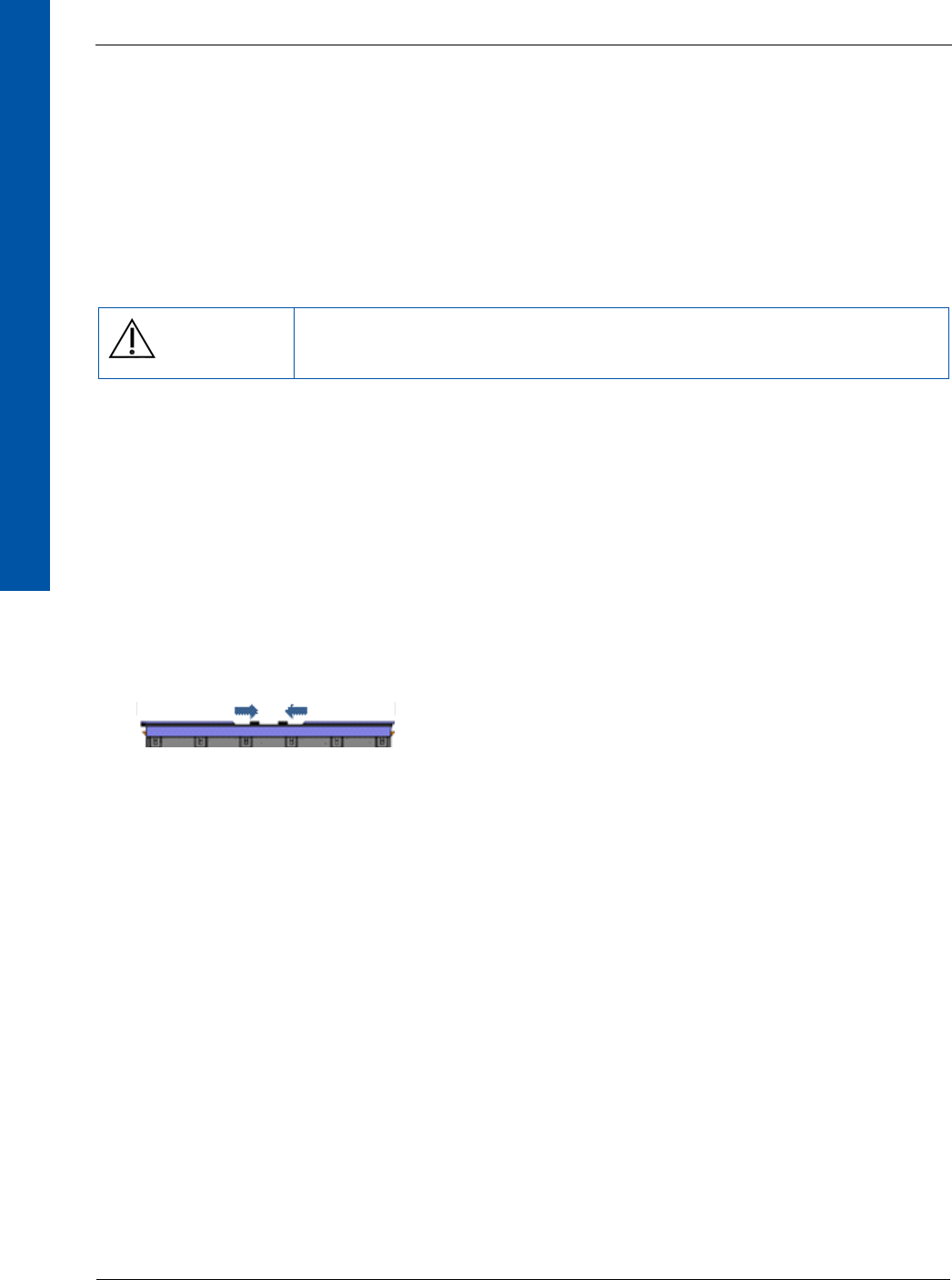
8.5.1.3 Removing the XRpad2 LBP
To remove the XRpad2 LBP:
1Fully support the X-ray detector and XRpad2 LBP before performing this task to prevent
them from dropping or slipping.
2Power off the X-ray detector by pressing the Power button on the X-ray detector.
3Move the two sliding latches closer to the center to disengage the XRpad2 LBP from the X-
ray detector (see Figure 5). Remove the XRpad2 LBP from the battery compartment of the X-
ray detector using a slow and steady pulling motion, supporting both the X-ray detector and
the XRpad2 LBP.
4Store the XRpad2 LBP in a cool, dry, clean environment if not in use or when recharging the
XRpad2 LBP for the next use.
Figure 5 Removing the XRpad2 LBP
8.5.1.4 Transportation and Storage
When transporting and storing the XRpad2 LBP:
•Follow all local, state, and federal/national regulations for handling, packaging, labeling,
and transporting Lithium-Ion batteries.
•Before transporting the battery, inspect it to confirm that there is no damage or leakage from
the battery.
•When possible, transport the battery in a discharged state.
•Transport the battery in approved packaging only. Retain the original packaging, inclusive of
the Safety Data Sheet (SDS), for transporting the battery.
•Store the battery in a cool, dry, clean environment if not in use. Do not remove the battery
from its original packaging until required for use.
Caution Dispose of a used XRpad2 LBP according to the instructions in
“Section 11.0, Disposing of the X-ray Detector” on page 35.

68153 01 www.perkinelmer.com 17
XRpad2 4336
DIGITAL IMAGING
•Store within approved temperatures: -20°C to 45°C for short periods (less than one month).
Recommended storage conditions are 15°C to 35°C, 85% RH Max.
•Do not leave or store the battery in extremely hot or cold temperatures (for example, in direct
sunlight, cars, or car trunks). The battery may overheat causing fire, or performance life will
be shortened.
•Do not short-circuit the battery or store the battery without sufficient packaging in a location
where it may short-circuited. This may cause a risk of fire, an explosion, or a severe burn
hazard.
8.5.1.5 Maintaining the XRpad2 LBP
To maintain the XRpad2 LBP:
•Before inserting the XRpad2 LBP into the X-ray detector or XRpad LBC, inspect the XRpad2
LBP for signs of damage, defects, or abnormalities. Do not use damaged, defective, or
abnormal conditioned XRpad2 LBP.
•Check to ensure the XRpad2 LBP is clean, dry, and free of foreign contamination or debris.
If cleaning is necessary, see “Section 8.5.1.6, Cleaning the XRpad2 LBP” on page 17 for
cleaning instructions.
•The XRpad2 LBP has no repairable parts. Do not disassemble. No modification of this
product is allowed.
•If the XRpad2 LBP emits an odor or generates heat or in any way appears abnormal during
use, recharging, or storing, immediately remove it from the device or battery charger, and
stop using the XRpad2 LBP.
•Using a damaged or defective XRpad2 LBP may reduce function time or cause the X-ray
detector system to fail.
•If an XRpad2 LBP leaks, do not touch the leaking fluid. If the fluid touches your skin or eyes,
wash the affected area with clean, running water and immediately seek medical attention.
•If the XRpad2 LBP has not been used or charged for an extended period of time
(approximately 30 days), check the condition of the XRpad2 LBP, and recharge if necessary
before using.
8.5.1.6 Cleaning the XRpad2 LBP
To clean the XRpad2 LBP:
•Avoid exposure of the XRpad2 LBP to liquids and solvents when possible.
•Do not allow liquids or solvents to contact the electrical contacts on the XRpad LBP.
•When necessary, clean the XRpad2 LBP using a lightly moistened cloth with 70% isopropyl
alcohol or 3% hydrogen peroxide.
•Never use thinner, benzene, acetone, or any other corrosive or flammable cleaning agents.
•Ensure the XRpad2 LBP is completely clean and dry before storing inserting the XRpad2 LBP
into the X-ray detector, or inserting the XRpad2 LBP into the XRpad LBC.
XRpad2 4336
18 68153 01
DIGITAL IMAGING
8.5.1.7 Disposing of the XRpad2 LBP
To dispose of the XRpad2 LBP:
•The XRpad2 LBP shall not be disposed with other waste at the end of its
working life.
•Recycle or dispose the battery in accordance with local, state, and federal/national laws and
environmental regulations.
•Do not place the battery in fire or incinerate.
•For transporting, follow the requirements in “Section 8.5.1.4, Transportation and Storage” on
page 16.
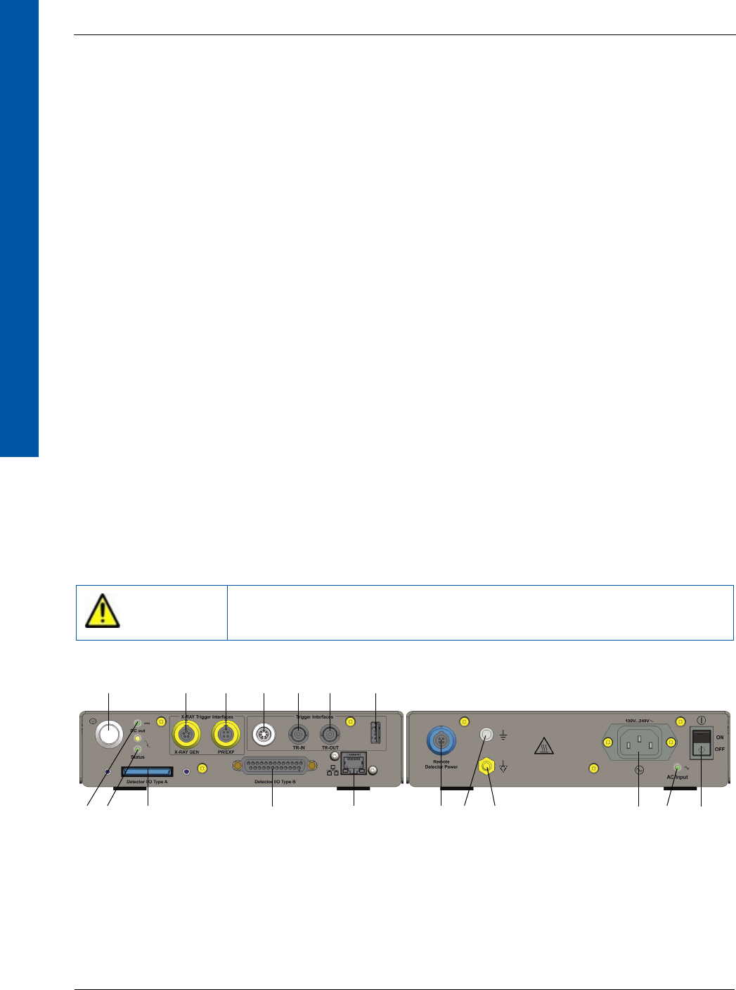
8.5.2 XRpad IPU-2
The XRpad IPU-2 is an Interface and Power Unit. The XRpad IPU-2 combines the Power Supply
Unit with additional communication and trigger interfaces. The tethered power and communica-
tion cable is connected to the X-ray detector. The communication data are split inside the XRpad
IPU-2 into Gigabit Ethernet Interface, Detector Trigger Interface, Hand Switch and Generator
Interface, and Detector Push Button Interface. The Gigabit Ethernet Interface of the XRpad IPU-2
is connected to the Imaging Workstation using a Cat 5e/6 cable. The maximum cable length is
31m. The AC cable must be connected to a properly grounded receptacle. The AC cable is remov-
able and will be plugged to an IEC connector. The XRpad IPU-2 must be connected with a
ground by the functional ground connector (Figure 6 [13]) or with the potential of the hospital by
the potential equalization connector (Figure 6 [12]). The socket outlet shall be near the XRpad
IPU-2 and shall be easily accessible. To isolate the equipment electrically from supply main on all
poles simultaneously, the supply main switch (Figure 6 [1]) must be used.
Figure 6 XRpad IPU-2
WARNING Connecting the XRpad IPU-2 LAN port directly to the clinical
computer network may disturb the IT environment.
Front Panel Rear Panel
1
23 4
567
8
910
11
12
13 14 15 16 17 18

68153 01 www.perkinelmer.com 19
XRpad2 4336
DIGITAL IMAGING
Table 10 includes an overview of the XRpad IPU-2.
I
Table 10 Overview of the XRpad IPU-2
1XRpad Push Button ( )
2 DC Output LED (Yellow) ( )
LED Yellow DC Output OK, no output load
LED Green DC Output OK, output loaded
3 Status LED (Yellow) ( )
LED Yellow N/A
LED Green N/A
4 XRpad Interface and Power I/O (1)
5 Trigger Out Signal to Generator
6 Trigger In Signal from Hand Switch (Prep/Expose)
7Trigger In/Out I/F
8 XRpad Interface and Power I/O
9TRIG IN Signal
10 TRIG OUT Signal
11 LAN Port to Imaging Workstation
12 USB Connector
13 Remote Detector Power
14 Potential Equalization Connector
15 Functional Ground Connector
16 Power In
17 AC Input LED (Green) ( )
18 XRpad IPU-2 Power Switch
XRpad2 4336
20 68153 01
DIGITAL IMAGING
Table 11 includes the specification for the XRpad IPU-2.
Table 11 Specification of the XRpad IPU-2
Electrical Specification
AC Input Voltage [16] 100 V … 240 V
AC Frequency [16] 50 Hz/60 Hz
DC Output [8] 12.5 V/5 A, 15 V/1 A
(voltage level is dependent of load)
Trigger In Signal from Hand Switch [6] 5 V … 24 V/10 mA (SELV)
Trigger Out Signal to Generator [5] Same level as Trigger In Signal
Trigger In Signal [7, 9] 3.3 V … 5 V (SELV)
Trigger Out Signal [7, 10] 3.3 V
DC Output 5PF [7] 5 V/100 mA
Mechanical Specification
Size 260 mm (L) × 205 mm (W) × 50 mm (H)
Temperature Ranges
Operating 10°C to 35°C
Transportation/Storage –10°C to 70°C
Relative Humidity
Operating 10% to 90%
Transportation/Storage 0% to 90%
Ingress Protection Rating
IP40 rated (protection against particles > 1 mm)
WARNING All external signals that are connected to the IPU-2 (especially PREP/
EXPOSE and Trigger signals) should be from a Separated or Safety
Extra-Low Voltage (SELV) circuit. Ignoring this warning may result in
electric shock, which may result in severe personal injury, death, or
substantial product damage.

68153 01 www.perkinelmer.com 21
XRpad2 4336
DIGITAL IMAGING
8.5.2.1 Cleaning the XRpad IPU-2
If the XRpad IPU-2 (Interface and Power Unit) surface is dirty or dusty, clean it with a cleaning
cloth dampened with ethanol or a diluted neutral detergent. If you are using a disinfectant other
than those specified, we recommend you consult a specialist for the procedure for disinfection.
Turn off the XRpad IPU-2, and disconnect the AC power cable, detector power, and detector
communication tethered cables before cleaning.
8.6 Minimum System Requirements
The following are the minimum requirements for the host computer that controls the X-ray
detector.
1Gigabit Ethernet Infrastructure and a free Gigabit Ethernet Port or Wi-Fi Infrastructure.
2Intel compatible Multi Core Processor (> 2 GHz).
3RAM > 4 GB.
4Windows 7 (32-bit/64-bit).
5If a Firewall is used, make sure that it allows a connection to the detector.
6Access Point:
aWPA2 encryption support.
b802.11n standard with 20 MHz channel bandwidth 36-48, 52-64, 100-116, 132-140,
149-165.
cMIMO 3x3.
dComplying with IEC 60601-1 or IEC 60950-1.
WARNING When the Interface Power Unit is going to be cleaned, be sure to turn
off the XRpad IPU-2 (Interface and Power Unit), and unplug all cables.
Never use thinner, benzine, acetone, or other flammable cleaning
agents. Ignoring this warning may result in explosion, fire, or electric
shock, which may result in severe personal injury, death, or
substantial product damage.
XRpad2 4336
22 68153 01
DIGITAL IMAGING
8.7 Operating the X-ray Detector
Before connecting the X-ray detector, ensure that the Digital Radiography Software is installed
as described in its manual. If not, install the software first. The X-ray detector can be used in
different configurations depending on the desired application. The following sections describe
the different use cases.
WARNING Do not exceed the maximum uniform load weight of 150 kg
distributed across the surface of the X-ray detector.
WARNING Do not exceed the maximum load weight of 100 kg distributed at one
location in a 40mm diameter of the X-ray detector surface.
Caution Check the threshold of the auto trigger mode regularly.
Caution Do not acquire images and calibration files while handling the
detector. This can disturb the image quality and result in the wrong
diagnosis.
68153 01 www.perkinelmer.com 23
XRpad2 4336
DIGITAL IMAGING
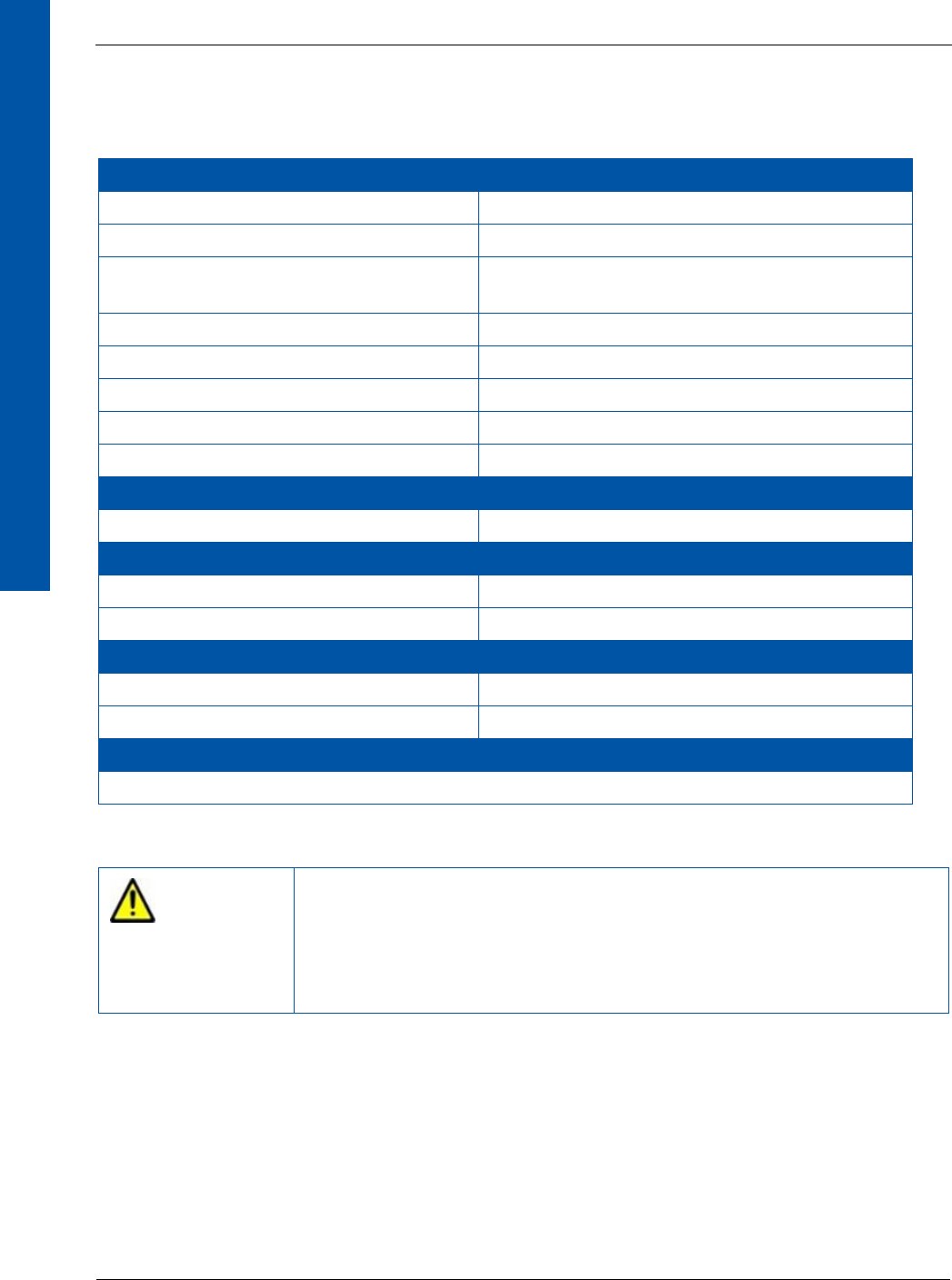
8.7.1 Wired X-ray Detector Connection
Figure 7 shows the wired connection of the X-ray detector in a clinical environment. In the wired
application, the X-ray detector is connected to the XRpad IPU-2, which powers the X-ray detector
and is responsible for the data transfer. The AC outlet should be installed near the XRpad IPU-2
and should be easily accessible.
Figure 7 Wired Connection of the X-ray Detector
The XRpad IPU-2 may be mounted in an equipment enclosure if there is adequate ventilation
within the equipment enclosure. The XRpad IPU-2 is connected to the Imaging Workstation
using a Cat 5e/6 cable. Make sure that the XRpad IPU-2 is not connected directly with the
clinical network. The Trigger I/F of the XRpad IPU-2 must be connected with the Generator
and with the Hand switch if the detector is used in external trigger mode.
The XRpad IPU-2 communicates using a standard Gigabit Ethernet network Interface and comes
equipped with an RJ45 interface port. Due to the overall network traffic, it is recommended that
you use this interface in a direct (Point-to-Point) connection with the host computer in order to
achieve optimal speed performance. The XRpad IPU-2 should be connected to the host computer
by one of the PerkinElmer XRD GigE Interface Cables or a CAT5e/CAT6 (shielded twisted pair,
stranded, or solid copper conductor) cable. The cable length can be up to 31 m.
Patient
X-Ray
Source
Interface
Power Unit
Generator
XRpad
Hand Switch
XRpad LPT Detector Cable
Imaging
Workstation
Cat 5e/6
Operator Room
Exposure Room
Battery
Pack
Battery Charger
XRpad2 4336
24 68153 01
DIGITAL IMAGING
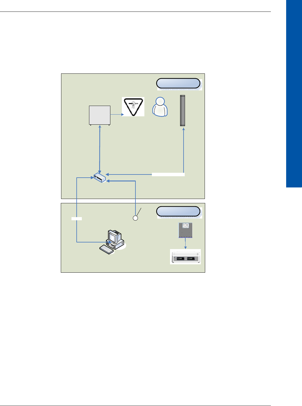
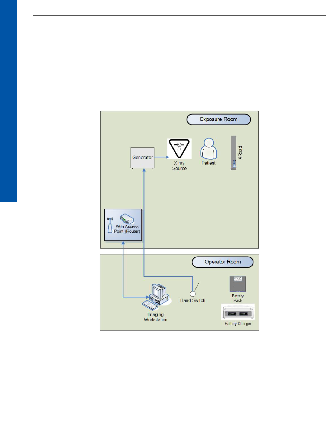
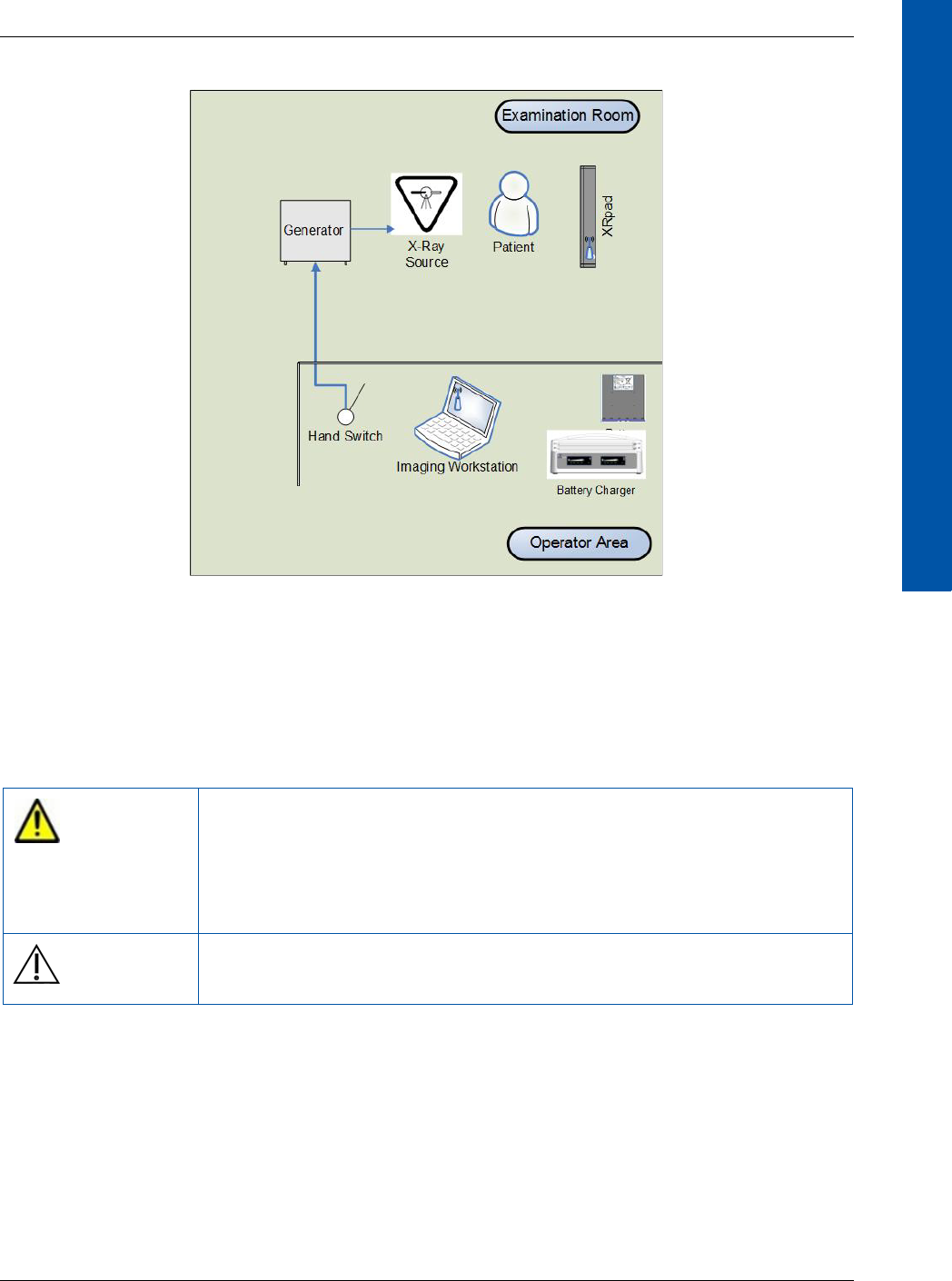
8.7.2 Wireless X-ray Detector Connection
Figure 8 shows the wireless connection of the X-ray detector in a clinical environment. The X-ray
detector is connected using WLAN over a Wi-Fi Access Point with the Imaging Workstation. The
Wi-Fi Access Point may be wall or ceiling mounted to maximize wireless signal strength. Make
sure that the router is not connected directly to the clinical network. The detector can also be
connected directly to the Imaging Workstation using WLAN with the WAP mode of the detector
(see Figure 9).Before imaging, make sure that the XRpad2 LBP charge is sufficient and the X-ray
detector antenna is not obstructed.
Figure 8 Wireless Connection of the X-ray Detector (Station/Client Mode)
68153 01 www.perkinelmer.com 25
XRpad2 4336
DIGITAL IMAGING
Figure 9 Wireless Connection of the X-ray Detector (WAP Mode)
8.7.3 Before Using the X-ray Detector
Sudden cooling or heating of the room will cause condensation. In this case, wait until
condensation disappears before powering on the X-ray detector.
WARNING If the X-ray detector system is used under conditions where
condensation can occur, problems in image quality or malfunction of
the detector system may occur. In addition, this may cause fire,
electrical shock, and unknown hazards, which may result in severe
personal injury, death, or substantial product damage.
Caution The X-ray detector should only be used with an inserted XRpad2 LBP
or XRpad2 Protective Insert.

XRpad2 4336
26 68153 01
DIGITAL IMAGING
8.7.4 Powering On the X-ray Detector
This section describes how to power on the X-ray detector. For more information, refer to the
Digital Radiography Software Manual. Ensure that the IP setting on your network adapter is set to
static IP and correlates to the X-ray detector. The default settings of the X-ray detector are
192.168.2.158 for the LAN connection and 192.168.22.1 for the WLAN connection with the
submask 255.255.255.0. The X-ray detector must have an XRpad2 Protective Insert or an XRpad2
LBP inserted into battery compartment.
8.7.4.1 Wired Mode
To power on the X-ray detector in wired mode:
1Plug in the power cord to the XRpad IPU-2, and switch the power on.
The AC Input LED turns on (green), and the DC Output LED turns on (yellow).
2To power on the X-ray detector, press the X-ray detector Power push button on the XRpad
IPU-2, or press the push button on the X-ray detector for one second.
The DC Output LED turns from yellow to green, and the detector push button LED turns ON
for a few seconds.
During the initialization of the detector, the detector push button LED starts flashing. Once
the X-ray detector is powered on, the X-ray detector display is on and shows the current
status of the X-ray detector. The X-ray detector LED will turn from flashing to constant on.
After the Radiography Imaging Software has initialized the detector, the X-ray detector LED
starts flashing.
8.7.4.2 Wireless Mode
To power on the X-ray detector in wired mode:
1When the detector is not connected to the XRpad IPU-2, check the status of the XRpad LBP
to ensure the charge of the battery is more than 50%. If the status is low, exchange the
XRpad2 LBP with a charged one, or use the wired operation mode.
2Press the X-ray detector’s push button for one second, and the X-ray detector will be
powered on, which is shown by the detector’s push button LED.
During the initialization of the detector, the detector push button LED starts flashing. Once
the X-ray detector is powered on, the X-ray detector display is on and shows the current
status of the X-ray detector including battery status. The X-ray detector LED will turn from
flashing to constant on. After the Radiography Imaging Software has initialized the detector,
the X-ray detector LED starts flashing.

68153 01 www.perkinelmer.com 27
XRpad2 4336
DIGITAL IMAGING
8.7.5 Powering Off the X-ray Detector
The X-ray detector is powered off by holding down one of the following three push buttons for
more than four seconds:
•X-ray detector (Figure 1 [5]) (wireless and wired mode).
•XRpad IPU-2 push button (Figure 6 [5]) (wired mode).
•Extended hand switch push button (wired mode)
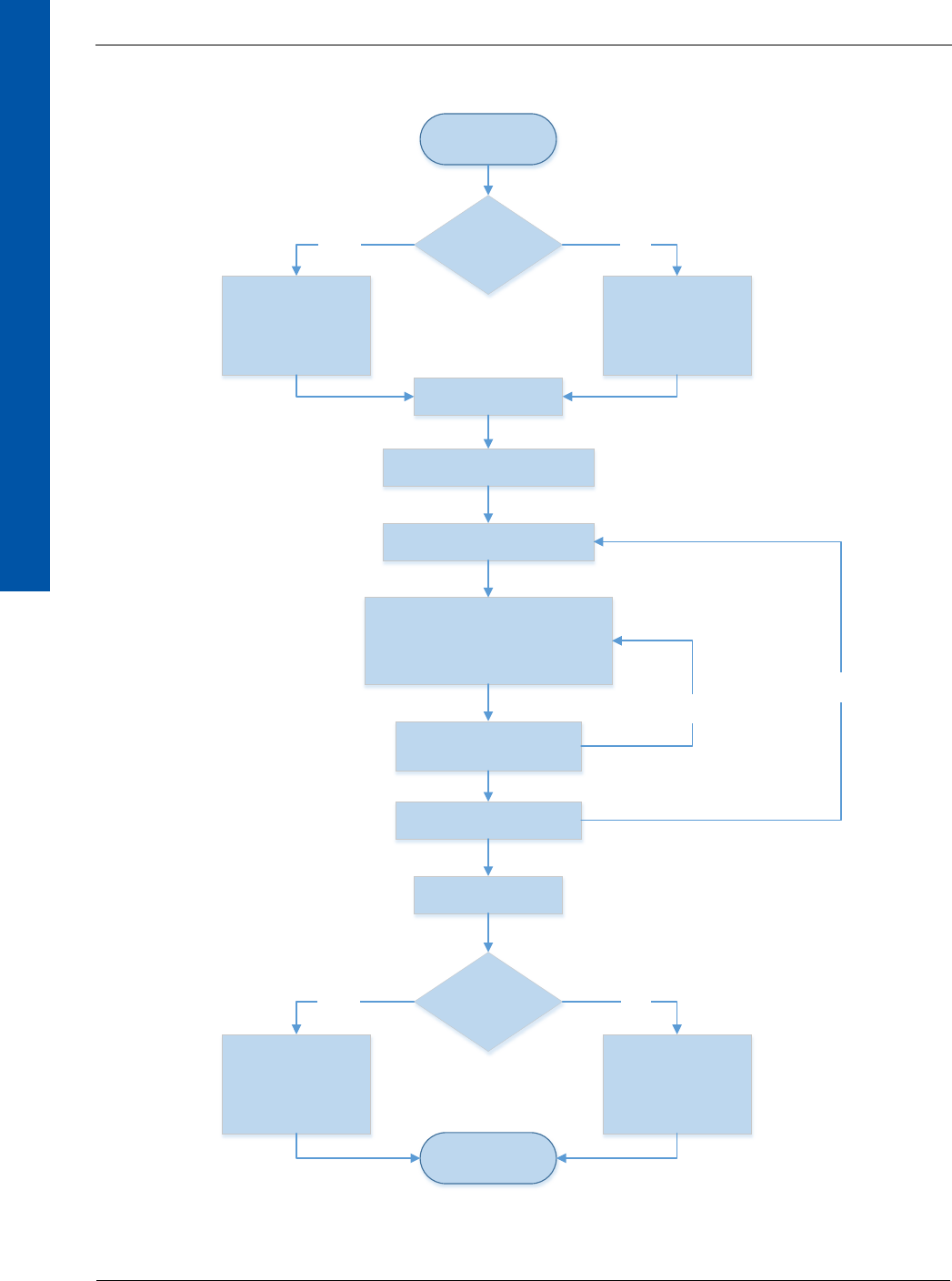
8.7.6 General Workflow for Acquiring an Image
Figure 10 shows the procedure for acquiring a clinical image after starting the Radiography
Imaging Software. Details of the Radiography Imaging Software and the X-ray generator are
described in their corresponding operation manuals.
XRpad2 4336
28 68153 01
DIGITAL IMAGING
Figure 10 Workflow for Acquiring an Image
Start
Communication
Mode
Attachafullycharged
batterypacktothe
detector
StarttheInterfacePower
Unit(IPU)
Turnonthedetector
Registerthedetectortothe
RadiographyImagingSoftware
Selectorregisterthepatient
information
Preparetheexaminationsetup:
x Arrangethepatient
x PositiontheXͲraycollimator
x Checkallconditions
x StarttheSoftwarecapturingbutton
Conducttheexamination:
x PressthePrepswitch
x PresstheExposureswitch
Checkthecapturedimages
Turnoffthedetector
Communication
Mode
Removethebatterypack
forrecharging
SwitchofftheInterface
PowerUnit(IPU)
End
Wireless Wired
Wireless Wired
Loopbackprocedure
foreachbodypart
Loopbackprocedure
foreachpatient

68153 01 www.perkinelmer.com 29
XRpad2 4336
DIGITAL IMAGING
9.0 Inspection and Maintenance
It is important that the X-ray detector is used safely and as intended. Inspect the detector and its
accessories before use. If any problem is found during the inspection, correct the problem, and
take the measures indicated in this section. The X-ray detector and the Interface and Power Unit
do not have any internal exchangeable parts. Only the accessories listed inTable 8 can be
changed after consulting your with establishment’s safety representative. If the problem cannot
be corrected, contact your dealer, distributor, device manufacturer, or any PerkinElmer subsid-
iaries (regional service headquarters) listed on the last page of this document.
We recommend that records of the inspection be kept close to the detector. You can use copies of
the checklist in this section, or you can make your own copies of the checklist.
9.1 Daily Inspection
Perform the following inspection daily. If there is any problem, immediately ask your establish-
ment’s safety representative to contact your dealer, distributor, or device manufacturer.
9.1.1 Before Turning On the Power
WARNING The X-ray detector must be repaired by PerkinElmer authorized
personnel only. Ignoring this warning may result in explosion, fire,
electric shock, or unknown hazards, which may result in severe
personal injury, death, or substantial product damage.
Caution Inspect the X-ray detector before use. In addition, carry out prescribed,
regular inspections per the instructions in this manual.
Inspection
Result
Remedy
Date
/
Date
/
Date
/
Cables
Check all cables, if
applicable, (Power and
communication tethered
cord, DC-cable, Ethernet
cable, Sync cable) to ensure
that they are not damaged
and the insulation is not
damaged.
Good/Bad Good/Bad Good/Bad Contact your dealer,
distributor, or device
manufacturer if there is a
problem.
Check all connector plugs
and locks to ensure they are
not loose.
Good/Bad Good/Bad Good/Bad Fully insert the cables and
lock them.

XRpad2 4336
30 68153 01
DIGITAL IMAGING
Inspection
Result
Remedy
Date
/
Date
/
Date
/
Detector
Check that the detector is
not damaged.
Good/Bad Good/Bad Good/Bad Contact your dealer,
distributor, or device
manufacturer if there is a
problem.
Check the manufacturing
date of the Battery Pack to
ensure that its age is not five
years or older.
Good/Bad Good/Bad Good/Bad Replace the Battery Pack with
a new one and recycle the old
one.
Check that the Battery Pack
(wireless mode) or the
Protective Insert (wired
mode) is in the battery
compartment and the
sliding latches are closed.
Good/Bad Good/Bad Good/Bad Slide the Battery Pack or the
Protective Insert into the
battery compartment as
described in “Section 8.5.1.3,
Removing the XRpad2 LBP”
on page 16.
Check that the Battery Pack
is not damaged.
Good/Bad Good/Bad Good/Bad Replace the Battery Pack with
a new one.
Check that the detector is
not loose and all screws are
fixed.
Good/Bad Good/Bad Good/Bad Contact your dealer,
distributor, or device
manufacturer if there is a
problem.

68153 01 www.perkinelmer.com 31
XRpad2 4336
DIGITAL IMAGING
9.1.2 After Turning On the Power
9.1.3 After Turning Off the Power
Inspection
Result
Remedy
Date
/
Date
/
Date
/
General
Check that the wireless
connectivity or the AP
symbol ( )is shown in
the display if wireless mode
is used.
Good/Bad Good/Bad Good/Bad Connect the X-ray detector
and the Wi-Fi Access Point as
described in the Access Point
Manual.
Check that the LAN
connectivity symbol ( ) is
shown in the display if the
wired mode is used.
Good/Bad Good/Bad Good/Bad Connect the Gigabit Ethernet
cable and the tethered power
and communication cable
properly.
Check the battery charge
condition (Battery Half or
better ( ).
Good/Bad Good/Bad Good/Bad Exchange the Battery Pack
with a charged one.
Check that the detector LED
is ON.
Good/Bad Good/Bad Good/Bad Set the Detector to Exposure
Ready as described in the
Digital Radiography Software
Manual.
Perform test exposure as
described in the Digital
Radiography Software
Manual.
Good/Bad Good/Bad Good/Bad If any error messages appear,
follow the instructions in the
Digital Radiography Software
Manual. If there is a problem,
contact your dealer,
distributor, or device
manufacturer.
Inspection
Result
Remedy
Date
/
Date
/
Date
/
General
Check that the X-ray
detector is turned off
normally and that all LEDs
are OFF.
Good/Bad Good/Bad Good/Bad See “Section 8.7.5, Powering
Off the X-ray Detector” on
page 27 for turning off the
X-ray detector.
Make sure that the X-ray
detector is clean and
disinfected.
Good/Bad Good/Bad Good/Bad See “Section 9.5, Cleaning the
X-ray Detector” on page 33
for cleaning the X-ray
detector.

XRpad2 4336
32 68153 01
DIGITAL IMAGING
9.2 Monthly Inspection
Perform the following inspection at least once a month. If there is a problem, immediately
ask your establishment’s safety department to contact your dealer, distributor, or device
manufacturer.
9.3 Yearly Inspection
Perform the following inspection at least once a year. If there is any problem, immediately ask your
establishment’s safety department to contact your dealer, distributor, or device manufacturer.
Inspection
Result
Remedy
Date
/
Date
/
Date
/
General
Execute the Dark Noise
and X-ray Uniformity tests
(refer to the XRpad2 4336
Digital X-ray Detector
System Reference Manual).
Good/Bad Good/Bad Good/Bad If there are changes in
performance, acquire new
calibration files as described
in the Digital Radiography
Software Manual.
Contact your dealer,
distributor, or device
manufacturer if there is any
problem.
Make sure that the XRpad
IPU-2 is clean from dirt or
dust.
Good/Bad Good/Bad Good/Bad Use the instructions in
“Section 8.5.1.6, Cleaning the
XRpad2 LBP” on page 17 for
cleaning.
Check the manufacturing
date of all Battery Packs to
ensure that their age is not
five years or older.
Good/Bad Good/Bad Good/Bad Replace the Battery Pack with
a new one and recycle the old
one.
Inspection
Result
Remedy
Date
/
Date
/
Date
/
General
Execute the Dark Noise,
X-ray Uniformity, Bad
Pixel, and Resolution tests
(refer to the XRpad2 4336
Digital X-ray Detector System
Reference Manual).
Good/Bad Good/Bad Good/Bad If there are changes in
performance, acquire new
calibration files as described
in the Digital Radiography
Software Manual.
Contact your dealer,
distributor, or device
manufacturer if there is any
problem.
68153 01 www.perkinelmer.com 33
XRpad2 4336
DIGITAL IMAGING
9.4 Calibrating the X-ray Detector
When exposure conditions have changed significantly (for example, new energy settings, new
X-ray tube, and new distances), acquire new gain calibration files. Follow the instructions in the
Digital Radiography Software Manual for acquiring new calibration files. Never acquire calibration
files while handling or transporting the detector.
9.5 Cleaning the X-ray Detector
To clean the X-ray detector:
1Turn off the X-ray detector and the power and communication tethered cable, if applicable.
2Insert the XRpad2 Protective Insert into the battery compartment before cleaning or
disinfecting the detector.
3If the detector surface is dirty, clean it with a cleaning cloth dampened with ethanol or a
diluted neutral detergent.
Do not allow any fluid, detergent, or solution to get inside the battery compartment of the
X-ray detector.
4Remove any excess detergent or solution.
5Wipe the X-ray detector surface with a clean cloth to completely dry the X-ray detector.
6Allow the X-ray detector to completely air dry before turning on or storing the X-ray
detector.
WARNING Do not acquire images and calibration files while handling the
detector. This can disturb the image quality and result in the wrong
diagnosis.
WARNING When the detector system is going to be cleaned, be sure to turn off
X-ray detector and remove the battery. If the detector is connected to a
power supply, turn off the power switch and/or unplug the power and
communication tethered cable, if applicable. If the X-ray detector is
battery powered, remove the battery. Never use thinner, benzine,
acetone, or other flammable cleaning agents. Ignoring this warning
may result in explosion, fire, or electric shock, which may result in
severe personal injury, death, or substantial product damage.
Note If you are using a disinfectant other than those specified, we recommend
you consult a specialist for the procedure for disinfection.

XRpad2 4336
34 68153 01
DIGITAL IMAGING
9.6 Error Messages and Troubleshooting
If any error messages appear, follow the instructions in the Digital Radiography Software Manual.
If there is any problem that is not described in the manual, immediately ask your establishment’s
safety representative to contact your dealer, distributor, or device manufacturer. Further use
may result in severe personal injury, death, or substantial product damage.
10.0 After-Sales Service for PerkinElmer Products
Contact your sales person, distributor, or device manufacturer for after-sales service (including
warranty) or any other information. If information is not available, contact one of the Perkin-
Elmer subsidiaries (regional service headquarters) listed on the last page of this document.
Field service is limited to replacement of the detector or adding and replacing approved accesso-
ries by authorized personnel. The detector and its accessories are not intended to be repaired in
the field.
For product returns, contact your distributor or device manufacturer for shipping and packaging
instructions. Do not return products to PerkinElmer for repair or service without advance notifi-
cation. Include all required papers in the shipment.
If the X-ray detector or accessories have been contaminated with potentially harmful substances
or activated by high energy X-rays, gamma rays, or neutrons, they cannot be accepted without
written evidence of decontamination.
To ship the XRpad2 LBP, follow the local and regional requirements for proper packaging and
shipping of Lithium Batteries.
WARNING If any abnormal condition, such as smoke, fumes, or strange sounds, is
evident, turn off the X-ray detector, turn off and unplug the power
supply from the AC outlet, and immediately ask your establishment’s
safety representative to contact your dealer, distributor, or device
manufacturer.
Further use under abnormal conditions may result in severe personal
injury, death, or substantial product damage.

68153 01 www.perkinelmer.com 35
XRpad2 4336
DIGITAL IMAGING
11.0 Disposing of the X-ray Detector
If the X-ray detector is activated by high energy X-rays, gamma rays, or neutrons follow the local
radiation protection regulation.
Contact your supplier or distributor, and check the terms of conditions of the purchase contract.
This product should not be mixed with other commercial waste for disposal.
A label with a crossed-out wheeled bin symbol and a rectangular bar indicates that
the product is covered by the Waste Electrical and Electronic Equipment (WEEE)
Directive and is not to be disposed of as unsorted municipal waste. Any products
marked with this symbol must be collected separately, according to the regulatory
guidelines in your area.
The objectives of this program are to preserve, protect, and improve the quality of the environ-
ment, protect human health, and utilize natural resources prudently and rationally. Specific
treatment of WEEE is indispensable in order to avoid the dispersion of pollutants into the recy-
cled material or waste stream. Such treatment is the most effective means of protecting the cus-
tomer’s environment.
Requirements for waste collection, reuse, recycling, and recovery programs vary by regulatory
authority at your location. Contact your local responsible body (for example, your hospital,
clinic, establishment, or site manager) or authorized representative for information regarding
applicable disposal regulations. Contact PerkinElmer at the following web site for information
specific to PerkinElmer products.
Web Address:
http://www.perkinelmer.com/pages/010/onesource/environmental-health-and-
safety/environmental-directives-compliance.xhtml
The PerkinElmer product may be attached as part of a component to other manufacturers’
systems. These other manufacturers are directly responsible for the collection and processing of
their own waste products under the terms of the WEEE Directive. Contact these producers
directly before discarding any of their products. Consult the PerkinElmer web site (above) for
producer names and web addresses.

XRpad2 4336
36 68153 01
DIGITAL IMAGING
12.0 Declarations
This section includes the manufacturers’ declaration of standards and/or regulations for which
the product complies.
12.1 Guidance and Manufacturer’s Declaration
Table 12 Guidance and Manufacturer’s Declaration of Electromagnetic Emissions
Guidance and Manufacturer’s Declaration of Electromagnetic Emissions
The X-ray detector is intended for use in the electromagnetic environment specified below. The installer,
X-ray system manufacturer, or user of the X-ray detector is responsible for the usage condition of the
detector to be within such environment.
Emissions Test Compliance Electromagnetic Environment – Guidance
RF-emissions CISPR 11 Group 1 The X-ray detector uses RF energy only for its internal
function; therefore, its RF emissions are very low and are
not likely to cause any interference in nearby electronic
equipment. Should any interference (EMC) be detected
with any other equipment, reposition the X-ray detector
or the other equipment away from each other.
RF-emissions CISPR 11 Class B (wireless)
Class A (wired)
The X-ray detector is suitable for use in industrial and
clinical environments in the wired mode.
In the wireless mode the X-ray detector is suitable for use
in all environments within Class B.
Should any interference (EMC) be detected with any other
equipment, reposition the X-ray detector or the other
equipment away from each other.
Harmonic emissions
IEC 61000-3-2
Class B (wireless)
Class A (wired)
Voltage fluctuations/
flicker emissions
IEC 61000-3-3
Complies

68153 01 www.perkinelmer.com 37
XRpad2 4336
DIGITAL IMAGING
Table 13 Guidance and Manufacturer’s Declaration of Electromagnetic Immunity
Guidance and Manufacturer’s Declaration of Electromagnetic Immunity
The X-ray detector is intended for use in the electromagnetic environment specified below. The installer,
X-ray system manufacturer, or user of the X-ray detector is responsible for the usage condition of the
detector to be within such environment.
Immunity Test IEC 60601 Test Compliance Electromagnetic Environment –
Guidance
Electrostatic
Discharge (ESD)
IEC 61000-4-2
Contact: 6 kV
Air: 8 kV
Contact: 6 kV
Air: 8 kV
Floors should be made of wood, concrete,
or ceramic tile. If floors are covered with
synthetic material, the relative humidity
should be at least 30%.
Electrical fast
transients (Burst)
IEC 61000-4-4
0.5 kV (AC)
1kV (DC)
0.5 kV (AC)
1kV (DC)
Mains power quality should be that of a
typical commercial and/or hospital
environment.
Transients-Surges
IEC 61000-4-5
1 kV /‘2 kV 1 kV /2 kV Mains power quality should be that of a
typical commercial and/or hospital
environment.
Power frequency
magnetic field
IEC 61000-4-8
3 A/m 3 A/m Power frequency magnetic fields should be
at levels characteristic of a typical location
in a typical commercial and/or hospital
environment.
Voltage dips and
short interruptions
IEC 61000-4-11
–95%/10 ms
–60%/100 ms
–30%/500 ms
>–95%/5000 ms
–95%/10 ms
–60%/100 ms
–30%/500 ms
>–95%/5000 ms
Mains power quality should be that of a
typical commercial or hospital
environment.
If the user of the X-ray detector requires
continued operation during power mains
interruptions, we recommend that the
X-ray detector be powered from an
uninterruptible power supply or battery.

XRpad2 4336
38 68153 01
DIGITAL IMAGING
Table 14 Recommended Separation Distance between Portable and Mobile RF-Communication
Equipment and the X-ray Detector
Recommended Separation Distance between Portable and Mobile RF-Communication Equipment
and the X-ray Detector
The X-ray detector is intended for use in the electromagnetic environment specified below. The installer,
X-ray system manufacturer, or user of the X-ray detector should assure that it is used in such an
environment.
Rated Maximum Output
Power of the
Transmitter (W)
150kHz to 80MHz 80MHz to 800MHz 800MHz to 2.5GHz
0.01 0.12 0.12 0.23
0.1 0.38 0.38 0.73
1 1.2 1.2 2.3
10 3.8 3.8 7.3
100 12 12 23
For a transmitter rated at a maximum output power not listed above, the separation distance can be
estimated using the equation in the corresponding column, where P is the maximum output (power
rating of the transmitter in watt [W]) according to the transmitter manufacture and d is the
recommended separation distance in meter (m).
Note: This guideline may not apply in all situations. Electromagnetic propagation is affected by
absorption and reflection from structures, objects, and people.
Pd 2.1
Pd 2.1
Pd 3.2
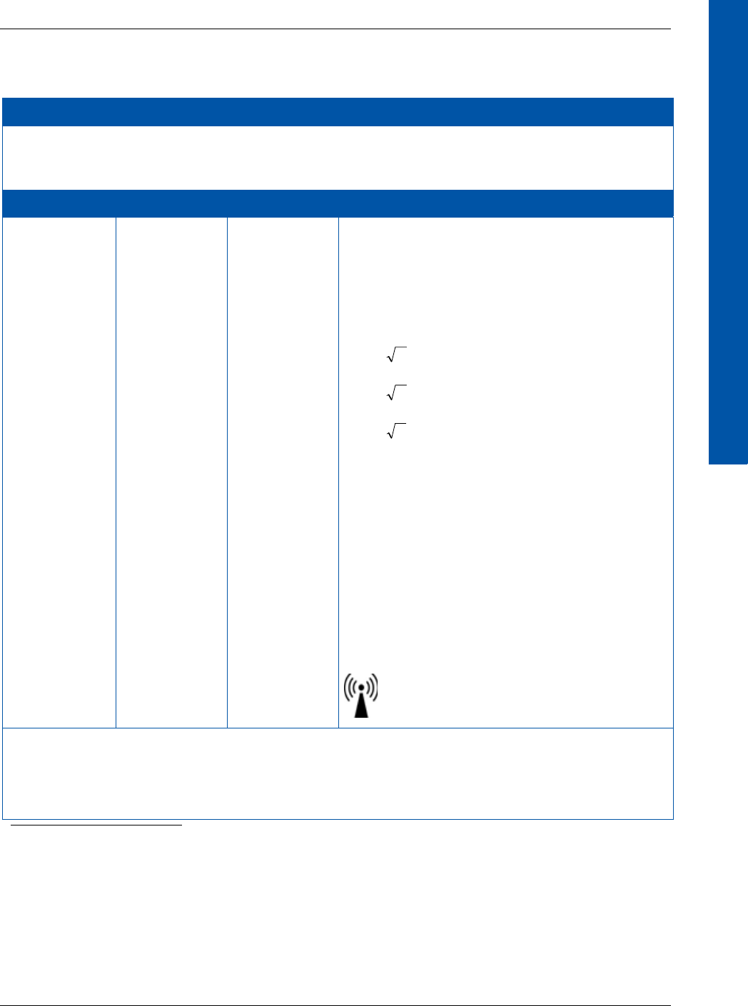
68153 01 www.perkinelmer.com 39
XRpad2 4336
DIGITAL IMAGING
Table 15 Guidance and Manufacturer’s Declaration of Electromagnetic Immunity
(Portable Equipment)
Guidance and Manufacturer’s Declaration of Electromagnetic Immunity
The X-ray detector is intended for use in the electromagnetic environment specified below. The installer,
X-ray system manufacturer, or user of the X-ray detector should assure that it is used in such an
environment.
Immunity Test IEC 60601 Test Compliance Electromagnetic Environment – Guidance
Conducted
radio-frequency
fields (CEF)
IEC 61000-4-6
Radiated
electromagnetic
field (REF)
IEC 61000-4-3
3V
150 kHz to
80 MHz
3V/m
80 MHz to
2.5 GHz
[V1] 3 V
150 kHz to
80 MHz
[E1] 3 V/m
80 MHz to
2.5 GHz
Portable and mobile RF-communication equipment
should not be closer to any part of the X-ray
detector including the data cables, than the
recommended separation distance calculated from
the equation appropriate for the frequency of the
transmitter.
, for 150 kHz to 80 MHz,
, for 80 MHz to 800 MHz,
, for 800 MHz to 2.5 GHz,
where P is the maximum output of the transmitter
in watt (W) according to the transmitter
manufacturer and d is the recommended
separation distance in meter (m).
Field strengths outside the shielded location from
fixed RF transmitters, as determined by an
electromagnetic site surveya, should be less than
3V/m.
Interference may occur in the vicinity of equipment
marked with the following symbol.
a. Field strengths from fixed transmitters, such as base stations for radio (cellular/cordless) telephones and land mobile radios,
amateur radio, AM and FM radio broadcast, and TV broadcast, cannot be predicted theoretically with accuracy. To assess the
electromagnetic environment due to fixed RF transmitters, an electromagnetic site survey should be considered. If the mea-
sured field strength in the location in which the X-ray detector is used exceeds the applicable RF compliance level above, the
X-ray detector should be observed to verify normal operation. If abnormal performance is observed, additional measures
may be necessary, such as re-orienting or relocating the X-ray detector.
Note 1: These guidelines may not apply to all situations. Electromagnetic propagation is affected by
absorption and reflection from structures, objects, and people.
Note 2: It is essential that the actual shielding effectiveness and filter attenuation of the shielded location
be verified to assure that they meet the minimum specification.
Pd 2.1
Pd 2.1
Pd 3.2

XRpad2 4336
40 68153 01
DIGITAL IMAGING
12.2 Declaration of Conformity for European Union
(and EEA)
English Hereby, PerkinElmer Inc. declares that this XRpad2 4336 is in compliance with the
essential requirements and other relevant provisions of Directive 1999/5/EC.
Česky PerkinElmer Inc. tímto prohlašuje, že tento XRpad2 4336 je ve shodě se základními
požadavky a dalšími příslušnými ustanoveními směrnice 1999/5/ES.
Dansk PerkinElmer Inc. erklærer herved, at denne XRpad2 4336 overholder de væsentlige krav
samt øvrige relevante bestemmelser i direktiv 1999/5/EF.
Deutsch Hiermit erklärt PerkinElmer Inc., dass der XRpad2 4336 den grundlegenden
Anforderungen und anderen einschlägigen Bestimmungen der Richtlinie 1999/5/EG
entspricht.
Eesti Käesolevaga kinnitab PerkinElmer Inc. seadme XRpad2 4336 vastavust direktiivi 1999/5/
EU põhinõuetele ja nimetatud direktiivist tulenevatele teistele asjakohastele
sätetele.
Español Por medio de la presente, PerkinElmer Inc. declara que el XRpad2 4336 cumple con
los requisitos esenciales y cualesquiera otras disposiciones aplicables o exigibles de la
Directiva 1999/5/CE.
Français Par la présente, PerkinElmer Inc. déclare que ce XRpad2 4336 est en conformité avec les
exigences essentielles et autres dispositions pertinentes de la directive 1999/5/CE.
Ελληνική ΜΕ ΤΗΝ ΠΑΡΟΥΣΑ Η PerkinElmer Inc. ΔΗΛΩΝΕΙ ΟΤΙ ΤΟ XRpad2 4336
ΣΥΜΜΟΡΦΩΝΕΤΑΙ ΠΡΟΣ ΤΙΣ ΟΥΣΙΩΔΕΙΣ ΑΠΑΙΤΗΣΕΙΣ ΚΑΙ ΤΙΣ ΛΟΙΠΕΣ ΣΧΕΤΙΚΕΣ
ΔΙΑΤΑΞΕΙΣ ΤΗΣ ΟΔΗΓΙΑΣ 1999/5/ΕΚ.
Italiano Con la presente, PerkinElmer Inc. dichiara che questo XRpad2 4336 è conforme ai requisiti
essenziali ed alle altre disposizioni pertinenti della direttiva 1999/5/CE.
Íslenska Her með lýsir PerkinElmer Inc. yfir þvi að XRpad2 4336 er í samræmi við
grunnkröfur og aðrar kröfur, sem gerðar eru í tilskipun 1999/5/EC.
Latviski Ar šo PerkinElmer Inc. paziņo, ka XRpad2 4336 atbilst Direktīvas 1999/5/EK būtiskajām
prasībām un citiem ar to saistītiem noteikumiem.
Lietuviu PerkinElmer Inc. patvirtina, kad šis XRpad2 4336 atitinka Direktyvos 1999/5/EB esminius
reikalavimus ir kitas nuostatas.
Malti Hawnhekk, PerkinElmer Inc., jiddikjara li dan XRpad2 4336 jikkonforma
mal-ħtiġijiet essenzjali u ma provvedimenti oħrajn relevanti li hemm fid-Dirrettiva
1999/5/EC.
Magyar Alulírott, PerkinElmer Inc. nyilatkozom, hogy az XRpad2 4336 megfelel a vonatkozó
alapvető követelményeknek és az 1999/5/EK irányelv egyéb előírásainak.
Nederlands Hierbij verklaart PerkinElmer Inc. dat het toestel XRpad2 4336 in overeenstemming is met
de essentiele eisen en de andere relevante bepalingen van richtlijn 1999/5/EG.
Norsk PerkinElmer Inc. erklærer herved at utstyret XRpad2 4336 er i samsvar med
de grunnleggende krav og øvrige relevante krav i direktiv 1999/5/EF.

68153 01 www.perkinelmer.com 41
XRpad2 4336
DIGITAL IMAGING
The XRpad2 4336 may be operated in the following countries:
Polski Niniejszym PerkinElmer Inc. oswiadcza, ze XRpad2 4336 jest zgodny z zasadniczymi
wymogami oraz pozostalymi stosownymi postanowieniami Dyrektywy 1999/5/EC.
Português PerkinElmer Inc. declara que este XRpad2 4336 está conforme com os requisitos essenciais
e outras disposicões da Directiva 1999/5/CE.
Suomi PerkinElmer Inc. vakuuttaa taten etta XRpad2 4336 tyyppinen laite on direktiivin 1999/5/
EY oleellisten vaatimusten ja sita koskevien direktiivin muiden ehtojen mukainen.
Slovensko PerkinElmer Inc. izjavlja, da je ta XRpad2 4336 v skladu z bistvenimi zahtevami in ostalimi
relevantnimi dolocili direktive 1999/5/ES.
Svenska Härmed intygar PerkinElmer Inc. att denna XRpad2 4336 står I överensstämmelse med de
väsentliga egenskapskrav och övriga relevanta bestämmelser som framgår av
direktiv 1999/5/EG.
AT BE BG CH CY CZ DE DK EE ES FI
FR GB GR HU IE IT IS LI LT LU LV
MT NL NO RO PL PT SE SI SK

XRpad2 4336
42 68153 01
DIGITAL IMAGING
12.3 Federal Communication Commission Interference
Statement (US)1
This device complies with Part 15 of the FCC Rules. Operation is subject to the following two
conditions: (1) This device may not cause harmful interference, and (2) this device must accept
any interference received, including interference that may cause undesired operation.
1. Section is only applicable to the US
Caution Any changes or modifications not expressly approved by PerkinElmer
Medical Imaging could void the user’s authority to operate the
equipment.
Note This equipment has been tested and found to comply with the limits for a
Class A digital device, pursuant to part 15 of the FCC Rules. These limits are
designed to provide reasonable protection against harmful interference
when the equipment is operated in a commercial environment. This
equipment generates, uses, and can radiate radio frequency energy and, if
not installed and used in accordance with the instruction manual, may cause
harmful interference to radio communications. Operation of this equipment
in a residential area is likely to cause harmful interference in which case the
user will be required to correct the interference at his or her own expense.
The country code selection is for non-US models only and is not available to
all US models. Per FCC regulation, all Wi-Fi products marketed in the US
must be fixed to US operation channels only.
IMPORTANT Radiation Exposure Statement: The product comply with the US portable
RF exposure limit set forth for an uncontrolled environment and are safe
for intended operation as described in this manual. The further RF
exposure reduction can be achieved if the product can be kept as far as
possible from the user body or set the device to lower output power if
such function is available.
This transmitter must not be co-located or operating in conjunction with
any other antenna or transmitter.

68153 01 www.perkinelmer.com 43
XRpad2 4336
DIGITAL IMAGING
12.4 Industry Canada Statement (English)2
This device complies with RSS-210 of the Industry Canada Rules. Operation is subject to the
following two conditions: (1) This device may not cause harmful interference, and (2) this device
must accept any interference received, including interference that may cause undesired
operation.
The product complies with the Canada portable RF exposure limit set forth for an uncontrolled
environment and are safe for intended operation as described in this manual. The further RF
exposure reduction can be achieved if the product can be kept as far as possible from the user
body or set the device to lower output power if such function is available.
2. Section is only applicable to Canada.
Caution The device for operation in the band 5150-5250 MHz is only for indoor
use to reduce the potential for harmful interference to co-channel
mobile satellite systems
WARNING The maximum antenna gain permitted for devices in the bands
5250-5350 MHz and 5470-5725 MHz shall comply with the e.i.r.p. limit.
WARNING The maximum antenna gain permitted for devices in the band
5725-5825 MHz shall comply with the e.i.r.p. limits specified for
point-to-point and non-point-to-point operation as appropriate.
WARNING Users should also be advised that high-power radars are allocated
as primary users (for example, priority users) of the bands
5250-5350 MHz and 5650-5850 MHz and that these radars could
cause interference and/or damage to LE-LAN devices.
Note This equipment does not exceed the Class A limits for radiated emissions as
described in the Radio Interference Regulations of the Canadian Department
of Communications.
XRpad2 4336
44 68153 01
DIGITAL IMAGING
12.5 Industrie Canada – Déclaration (Français)3
Le présent dispositif est conforme à la norme RSS-210 d'Industrie Canada. L'exploitation est
autorisée aux deux conditions suivantes : (1) ce dispositif ne doit pas causer d'interférences
nuisibles, et (2) ce dispositif doit accepter toute interférence reçue, y compris les interférences
susceptibles de causer un dysfonctionnement.
Le produit est conforme aux limites d'exposition pour les appareils portables RF pour les
Etats-Unis et le Canada établies pour un environnement non contrôlé. Le produit est sûr pour
un fonctionnement tel que décrit dans ce manuel. La réduction aux expositions RF peut être
augmentée si l'appareil peut être conservé aussi loin que possible du corps de l'utilisateur ou que
le dispositif est réglé sur la puissance de sortie la plus faible si une telle fonction est disponible.
Remarque: Cet appareil numérique ne dépasse pas les limites de la classe A pour les émissions
radio, telles que définies dans le Radio Interference Regulations du Département Canadien des
Communications.
Cet équipement ne dépasse pas les limites de la classe A pour les émissions rayonnées, telles que
définies dans le règlement sur le brouillage radioélectrique édicté par le ministère des Communi-
cations du Canada.
CAN ICES-3 (A)/NMB-3 (A)/CAN NMB-3(A)
3. Section is only applicable to Canada.
Mise en garde Le dispositif fonctionnant dans la bande 5 150-5 250 MHz est
réservé exclusivement à une utilisation en intérieur afin de réduire
les risques d'interférences nuisibles pour les systèmes mobiles par
satellite utilisant les mêmes canaux.
Mise en garde Le gain maximal d’antenne permis pour les dispositifs utilisant les bandes
5 250-5 350 MHz et 5470-5 725 MHz doit se conformer à la limite de p.i.r.e.
Mise en garde Le gain maximal d’antenne permis (pour les dispositifs utilisant la
bande 5 725-5 825 MHz) doit seconformer à la limite de p.i.r.e.
spécifiée pour l’exploitation point à point et non point à point,
selon le cas.
Mise en garde De plus, les utilisateurs devraient aussi être avisés que les utilisateurs
de radars de haute puissance sont désignés utilisateurs principaux (c.-à-d.,
qu’ils ont la priorité) pour les bandes 5 250-5 350 MHz et 5 650-5 850 MHz et
que ces radars pourraient causer du brouillage et/ou des dommages aux
dispositifs LAN-EL.

68153 01 www.perkinelmer.com 45
XRpad2 4336
DIGITAL IMAGING
12.6 Korean
Type of Equipment User’s Guide
A급 기기
(업무용 방송통신기자재 )
이 기기는 업무용 (A 급) 전자파적합기기로서 판
매자 또는 사용자는 이 점을 주의하시기 바라
며, 가정외의 지역에서 사용하는 것을 목적으로
합니다 .
주의 해당 무선설비는 전파혼신 가능성이 있으므로 인명안전과 관련된
서비스는 할 수 없음
해당 무선 설비는 5150-5250MHz 대역에서 실내 에서만 사용할
수 있음 .

This page intentionally left blank.
XRpad2 4336
46 68153 01

DIGITAL IMAGING
68153 01 www.perkinelmer.com 47
Index
A
abbreviations 2
accessories for the X-ray detector 11
acquiring an image, general workflow for 27
AED mode safety note ix
after
turning off the power 31
turning on the power 31
after-sales service for PerkinElmer products 34
alerts and notes, meaning of iii
audience 1
B
battery safety note vii
before
turning on the power 29
using the X-ray detector 25
you begin ii
C
calibrating the X-ray detector 33
charging the XRpad LBP 14
cleaning
X-ray detector 33
XRpad IPU-2 21
XRpad LBP 17
connection
wired X-ray detector 23
wireless X-ray detector 24
considerations, environmental 8
D
daily inspection 29
declarations 36
Federal Communication Commission
interface statement 42
guidance and manufacturer’s 36
Industrie Canada declaration 44
Industry Canada statement 43
Korean 45
of conformity of European Union and
EEA 40
definition of symbols 3
description
X-ray detector 6
XRpad IPU-2 18
dimensions for the X-ray detector 10
disposing of
X-ray detector 35
XRpad LBP 18
E
environmental considerations 8
F
Federal Communication Commission interface
statement 42
for your safety iii
G
general workflow for acquiring an image 27
guidance and manufacturer’s declaration 36
H
handling safety note vi
I
if a problem occurs safety note ix
image, workflow for acquiring 27
Industrie Canada declaration 44
Industry Canada statement 43
inspection
daily 29
monthly 32
yearly 32
inspection and maintenance 29
installation and environment of use safety
note iv
installing the XRpad LBP 15
interface and power unit and cables safety
note v
ionizing radiation, protection against ii
IPU-2. see XRpad IPU-2
K
Korean declarations 45
L
lithium battery pack. see XRpad LBP

DIGITAL IMAGING
48 www.perkinelmer.com 68153 01
Index XRpad2 4336
M
maintaining the XRpad LBP 17
maintenance and inspection 29
maintenance and inspection safety note x
meaning of alerts and notes iii
minimum system requirements 21
monthly inspection 32
N
notes and alerts, meaning of iii
O
operating the X-ray detector 22
overview
X-ray detector 6
XRpad IPU-2 19
P
patient vicinity 12
PerkinElmer products, after-sales service for 34
power
after turning off 31
after turning on 31
before turning on 29
powering off the X-ray detector 27
powering on
X-ray detector 26
X-ray detector in wired mode 26
X-ray detector in wireless mode 26
products, after-sales service for 34
protection against ionizing radiation ii
R
rechargeable lithium battery pack. see XRpad
LBP
references 3
regulations and standards 5
removing the XRpad LBP 16
S
safety note
AED mode ix
battery vii
handling vi
if a problem occurs ix
installation and environment of use iv
interface and power unit and cables v
maintenance and inspection x
WLAN viii
safety, for your iii
scope 1
service, after-sales for PerkinElmer products 34
specification
X-ray detector 9
XRpad IPU-2 20
XRpad LBP 14
standards and regulations 5
storage and transportation 16
symbols, definition of 3
system requirements, minimum 21
T
transportation and storage 16
turning off power, what to do after 31
turning on power
what to do after 31
what to do before 29
U
usage 1
using the detector, what to do before 25
V
vicinity, patient 12
W
wired mode
connection for 23
powering on X-ray detector 26
wireless mode
connection for 24
powering on X-ray detector 26
WLAN safety note viii
workflow for acquiring an image 27
X
X-ray detector
accessories 11
before using 25
calibrating 33
cleaning 33
description 6
dimensions 10
disposing of 35
operating 22
overview 6
powering off 27
powering on 26
powering on in wired mode 26
powering on in wireless mode 26
specification 9
wired connection 23
wireless connection 24


68153 01 www.perkinelmer.com 51
XRpad2 4336
DIGITAL IMAGING
USA
PerkinElmer Inc.
2175 Mission College Blvd
Santa Clara, CA 95054
USA
P: +1-844-726-8228
F: +1 408-969-6493
fpd@perkinelmer.com
www.perkinelmer.com
Germany
PerkinElmer Technologies GmbH & Co. KG
In der Rehbach 22
65396 Walluf
Germany
P: +49 6123 971-300
F: +49 6123 971-600
fpd@perkinelmer.com
www.perkinelmer.com
For a complete listing of our global offices, visit www.perkinelmer.com
©2015 PerkinElmer, Inc. All rights reserved. The PerkinElmer logo and design are registered trademarks of PerkinElmer, Inc. or its subsidiaries,
in the United States and other countries. All other trademarks not owned by PerkinElmer, Inc. or its subsidiaries that are depicted herein are the
property of their respective owners. PerkinElmer reserves the right to change this document at any time without notice and disclaims liability for
editorial, pictorial or typographical errors.