Varian Medical Systems VCDT711N Visual Coaching Device (VCD) User Manual UserManual
Varian Medical Systems, Inc. Visual Coaching Device (VCD) UserManual
UserManual.wiki
>
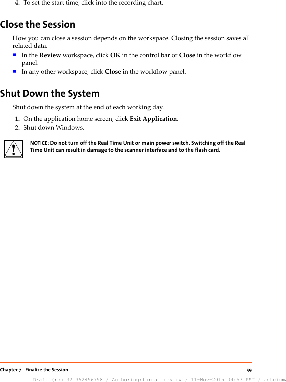
Varian Medical Systems
>
VCDT711N User Manual
>
UserManual.pdf
Contents
1.
UserManual.pdf
2.
UserManual_Safety.pdf
UserManual.pdf
Navigation menu
Upload a User Manual
Namespaces
Wiki Guide
HTML
PDF
Info
Views
User Manual
Discussion / Help
Navigation


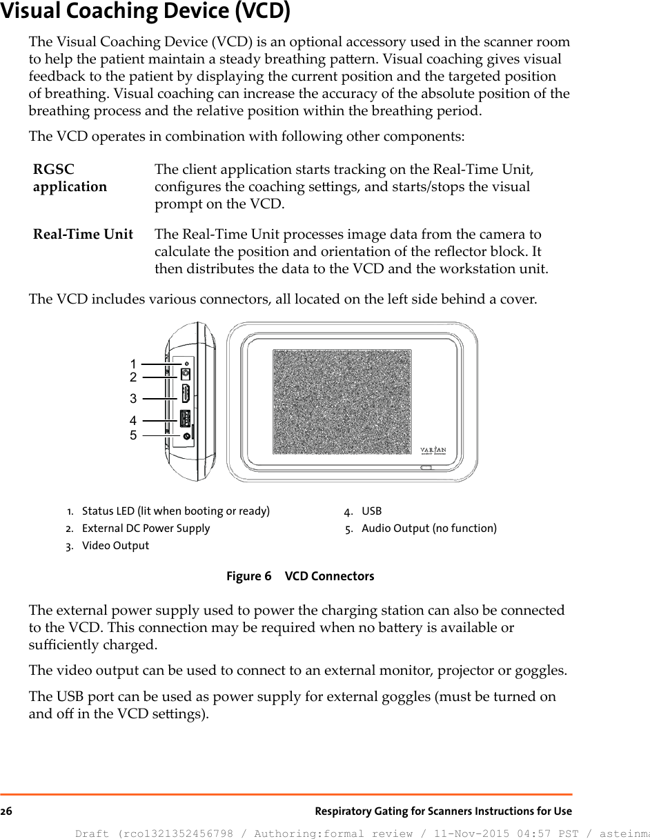
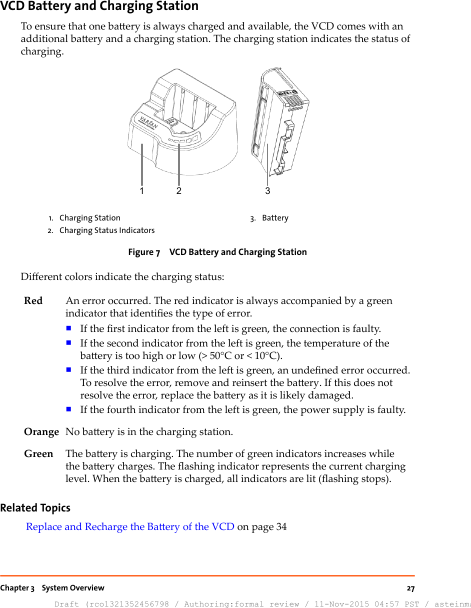

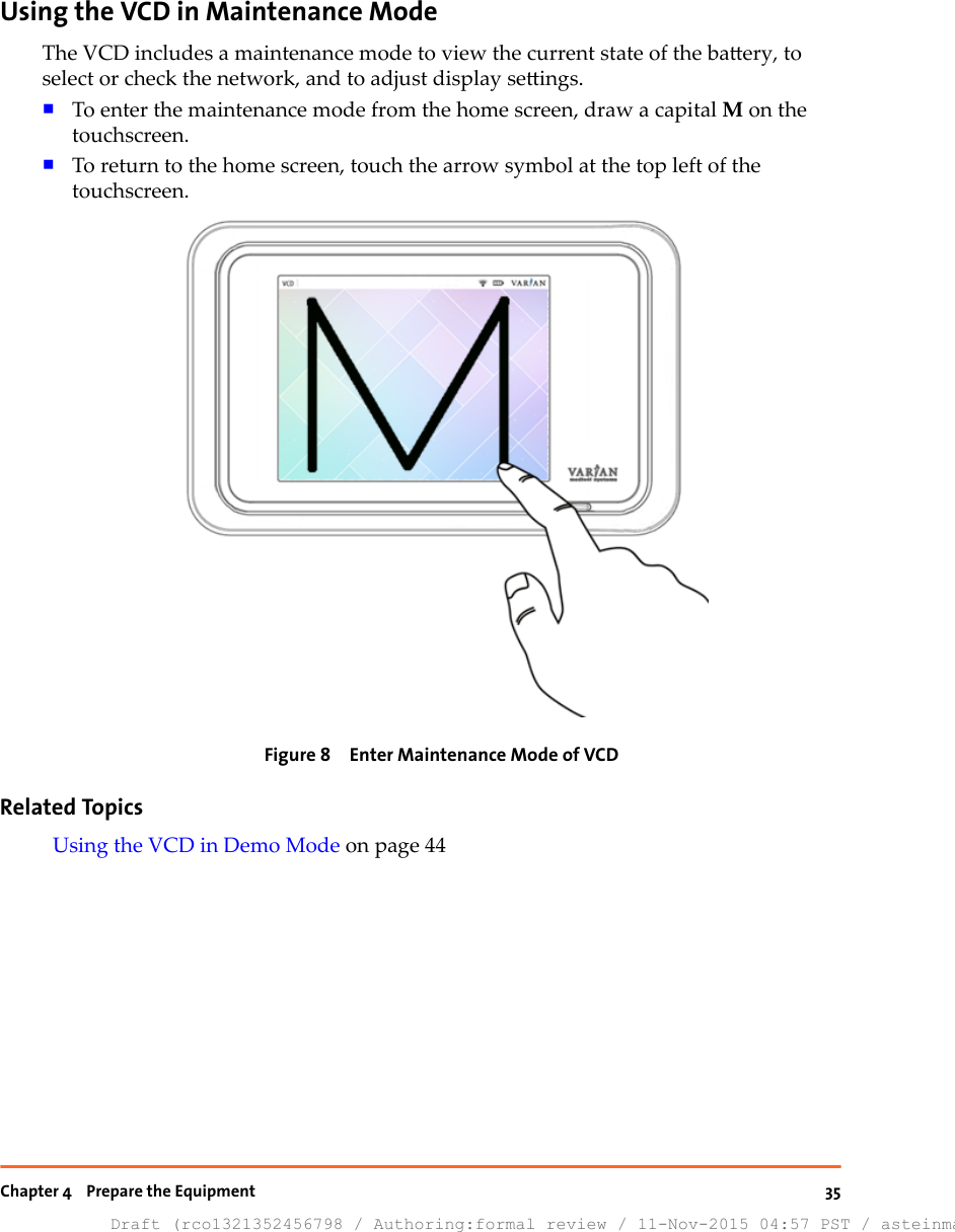
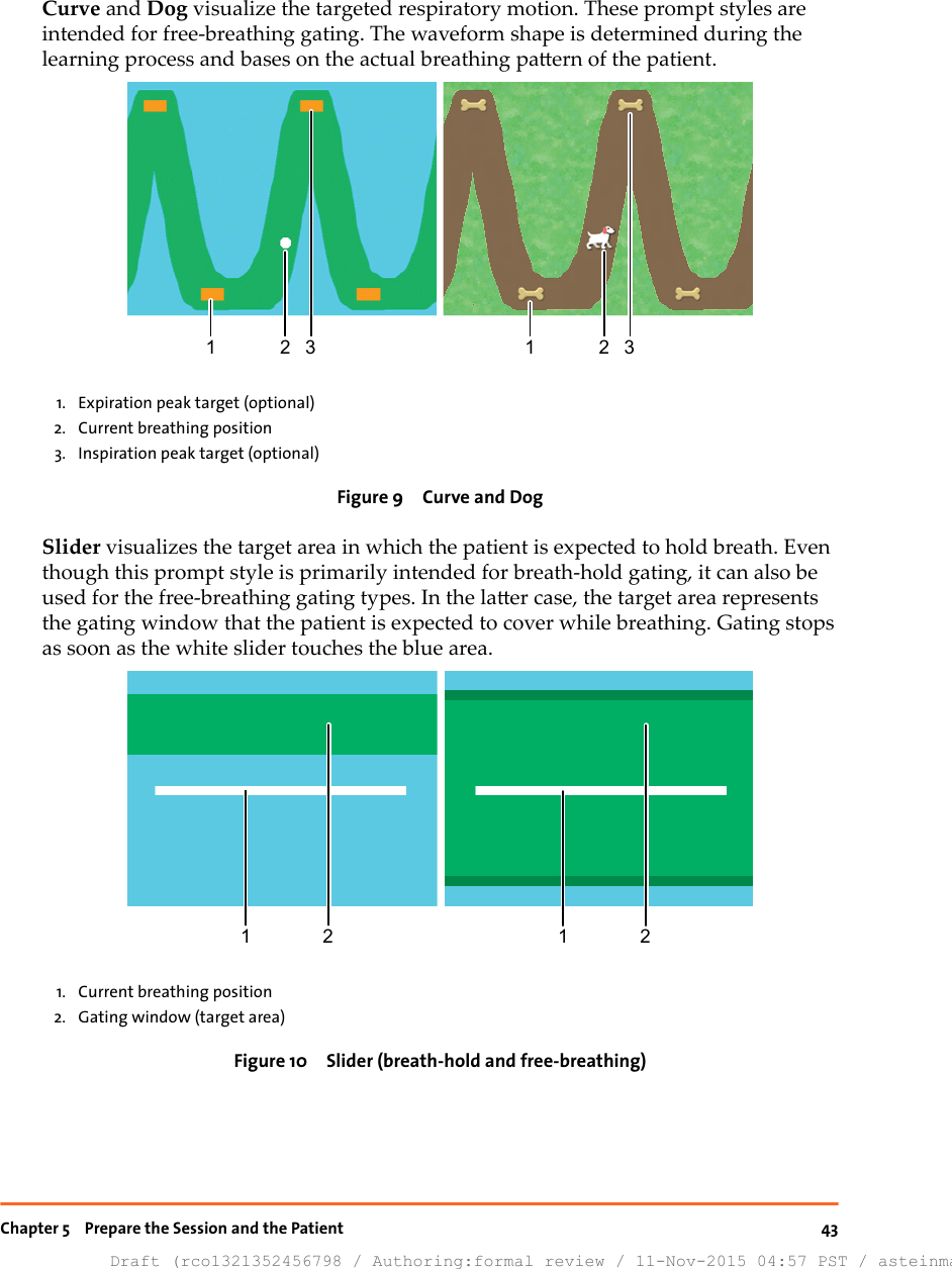
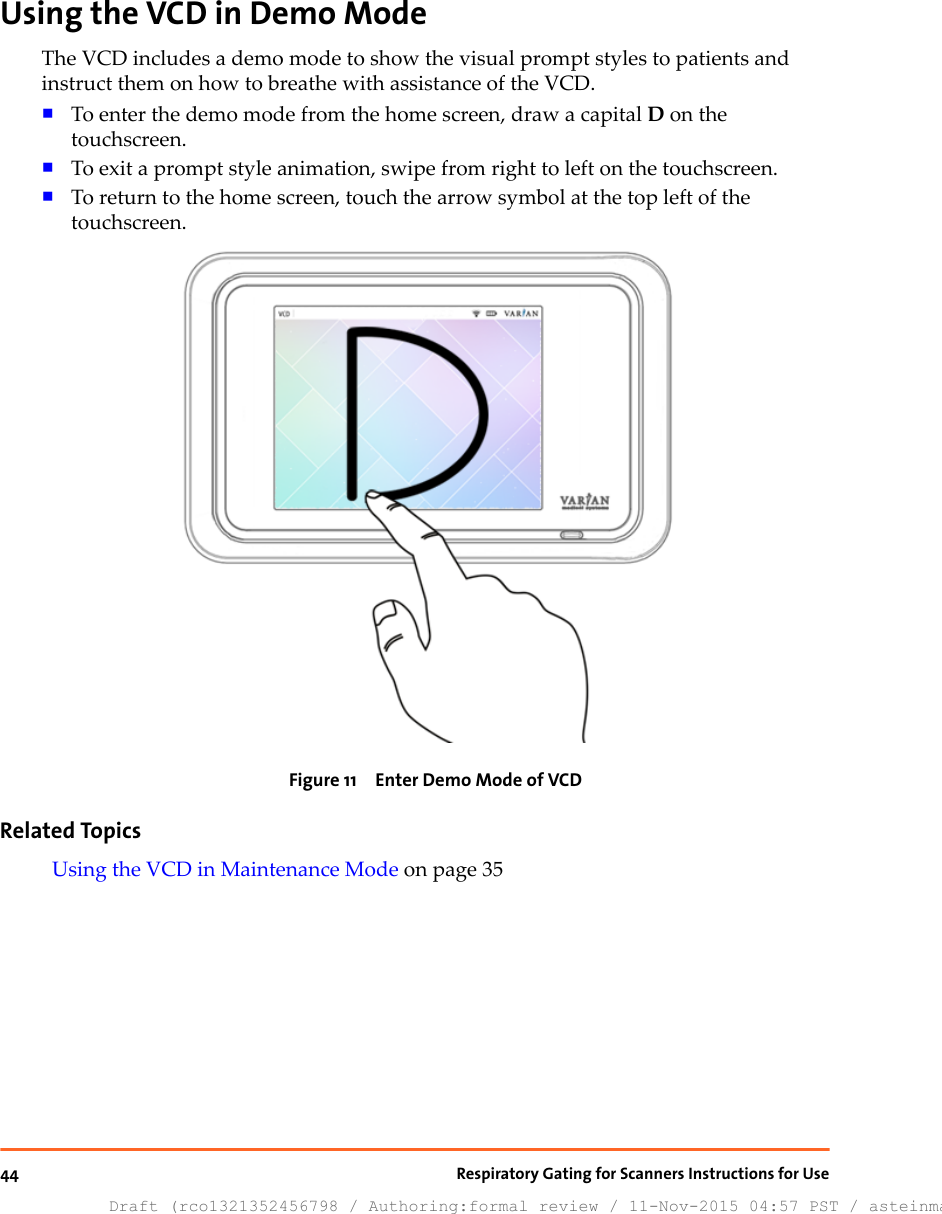
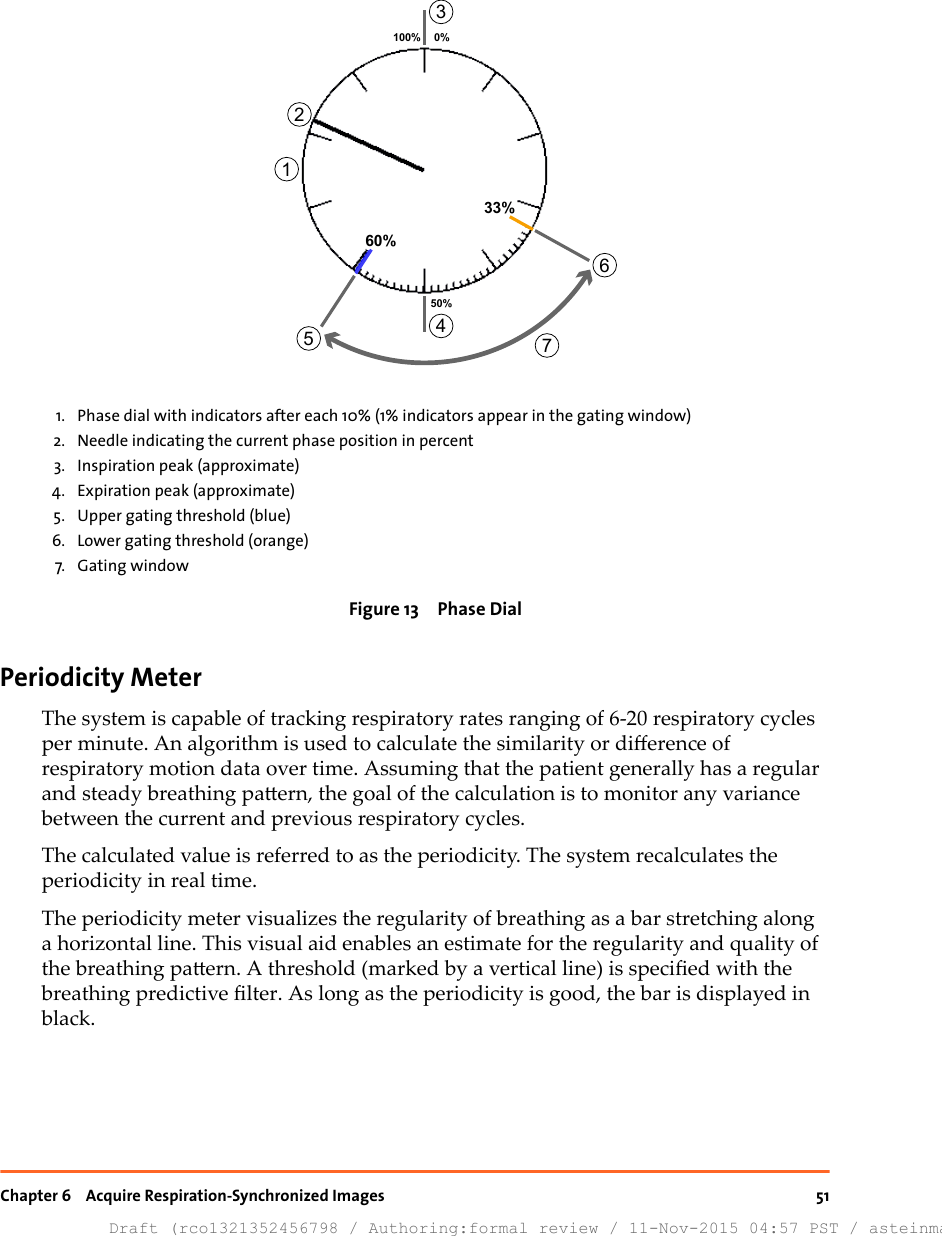
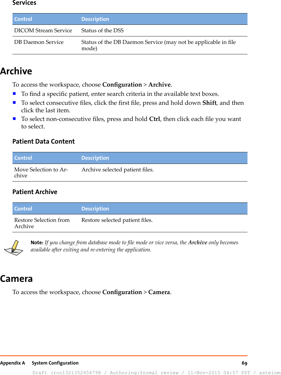
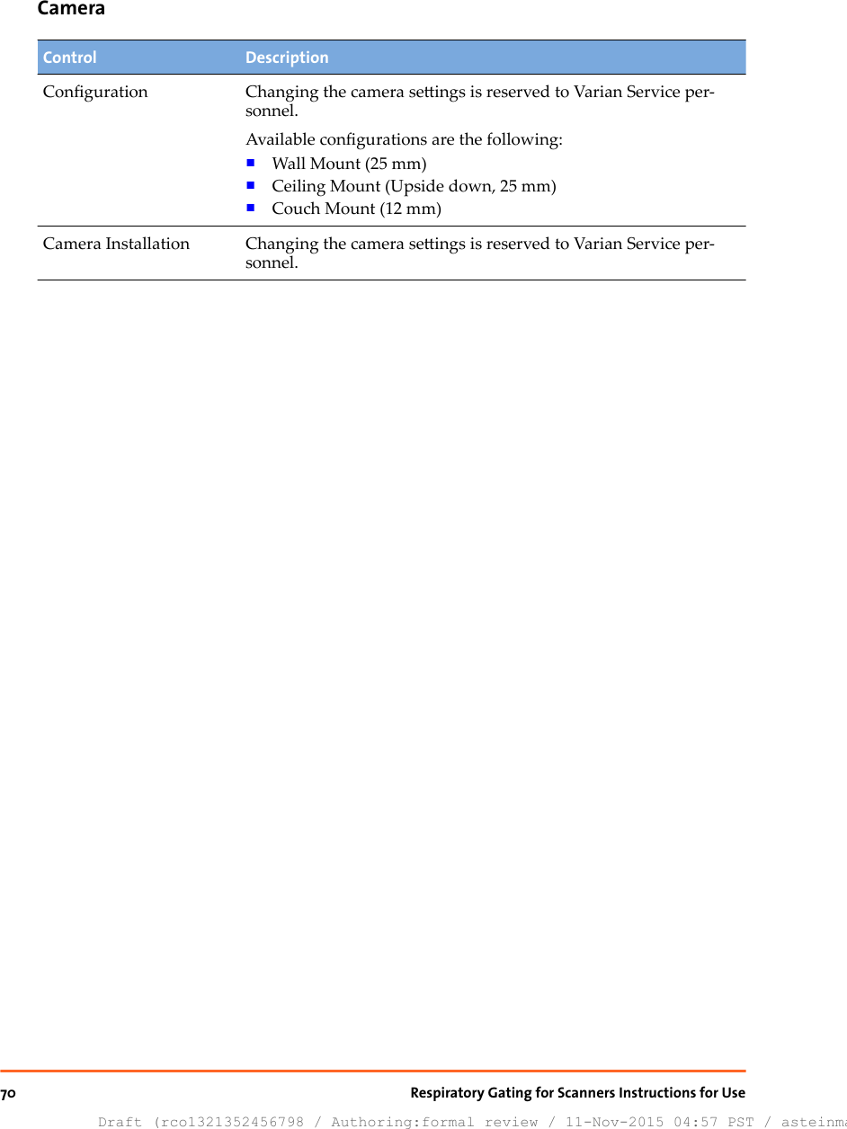
![CoachingControl DescriptionAudio Coaching Oset[s]Specify the oset according to the desired time lapse.Audio coaching starts with this oset before the inspiration or ex-piration peak is predicted.VerificationThis seing is only enabled in connection with a wall-mounted or ceiling-mountedcamera.Control DescriptionVerication Period [days] Specify the number of days during which the camera vericationis valid. If the verication is outdated, a new verication will beenforced.CalibrationThis seing is only enabled in connection with a couch-mounted camera.Control DescriptionCalibration Period [days] Specify the number of days during which the camera calibrationis valid. If the calibration is outdated, a new calibration will be en-forced.DICOM Import/ExportControl DescriptionSpecic Character Set Select the applicable character set.The applicable character set depends on the DB daemon or, if ap-plicable, on the TrueBeam system.ExportTo access the workspace, choose Conguration > Export.Appendix A System ConfigurationDraft (rco1321352456798 / Authoring:formal review / 11-Nov-2015 04:57 PST / asteinma)61](https://usermanual.wiki/Varian-Medical-Systems/VCDT711N.UserManual-pdf/User-Guide-2840853-Page-61.png)
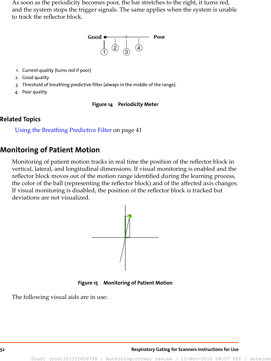
![Export File Structure and FormatThe system supports the export of motion data les for post-processing. Motion datales are created in text format after data acquisition is nished or when a previouslyrecorded session is retrieved.A text le is used for the export parameters. Depending on the scanner, the le namemust follow one of the following formats for 4D reconstruction.■PatientID_ExamNumber_SeriesNumber.vxp■PatientID_SessionNumber.vxpData contained in the export le is organized into a header section and a data section.The <cr> symbol represents a carriage return.Header SectionLine Data Format Description1 [Header]<cr> Prex of the header section2 CRC=crcChecksum<cr> CRC checksum3 Version=versionNumber<cr> The version number of the export le4Data_layout=eld1[,eld2...],eldn<cr>The layout of the data section; eld1 through eldnrepresent the names of the elds in the data section.5 Patient_ID=patId<cr> The Patient ID of the patient record created in RGSCsystem6 Date=mm-dd-yyyy<cr> The date the acquisition session was recorded7 Total_study_time=studyTime<cr>The actual recording length in seconds to a thou-sandth of a second8 Samples_per_second=sampl-eRate <cr>■NTSC: 30 or 15■CCIR: 25 or 12.59 Scale_factor=scale<cr> The scale factor for the signal data (in mm). For ex-ample, if the data eld ValueOfRespiratoryWave isgiven in cm, the scale factor is 10.0.Data SectionAt line 10, [Data]<cr> is used to demarcate the beginning of the data section, whosedata elds are separated by comma.The layout of the data section, is dened in line 4 of the header section. This version’sformat is described in the following table.Appendix A System ConfigurationDraft (rco1321352456798 / Authoring:formal review / 11-Nov-2015 04:57 PST / asteinma)63](https://usermanual.wiki/Varian-Medical-Systems/VCDT711N.UserManual-pdf/User-Guide-2840853-Page-63.png)
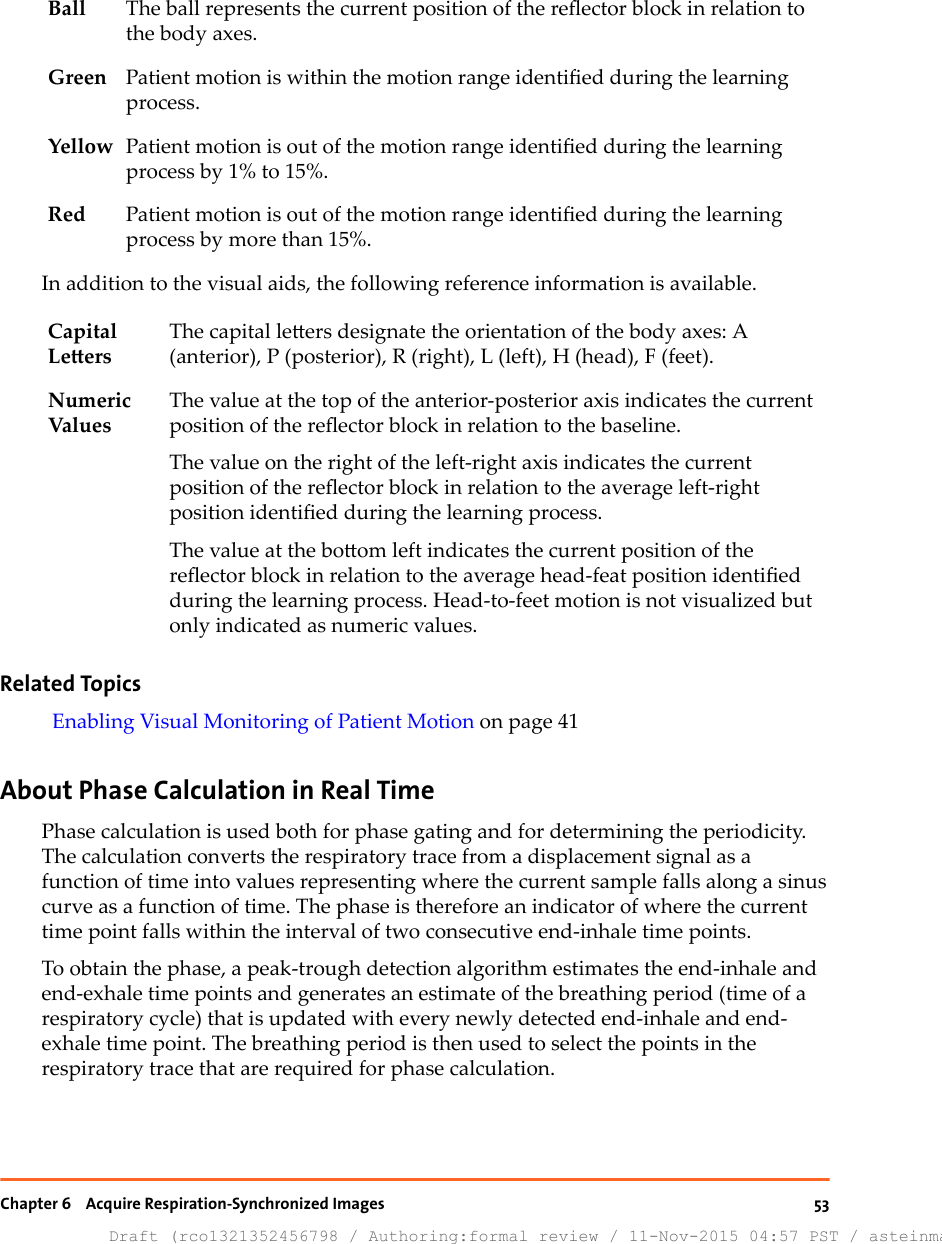
![Field DescriptionValue_of_respiratory_wave Position in centimeters relative to referencePhase_value Phase value for the current sampleTime_Stamp Time of the sample measurement in millisecondsValid_Flag ■≥ 0: a valid track and a periodic signal■< 0: either a lost track, a bad video signal, or a non-periodic signalTTL_In Bit value indicating the status of a sensed x-ray on signalfrom scanner■1: +5 VDC■0: 0 VDCMark Leer specifying the sample when the phase value isclosest to 0 or pi■Z: 0 phase■P: pi phase null string: no dataTTL_Out Bit value indicating the status of a gating signal to thescanner■1: +5 VDC■0: 0 VDCExampleThe following is a fragment of a sample export le:[Header]CRC=53224Version=1.6Data_layout=amplitude,phase,timestamp,validflag,ttlin,mark,ttloutPatient_ID=990310BDate=10-06-2012Total_study_time=32.533Samples_per_second=30Scale_factor=10.0[Data]4.7171,1.4994,29441,0,1,,064Draft (rco1321352456798 / Authoring:formal review / 11-Nov-2015 04:57 PST / asteinma)Respiratory Gating for Scanners Instructions for Use](https://usermanual.wiki/Varian-Medical-Systems/VCDT711N.UserManual-pdf/User-Guide-2840853-Page-64.png)
![4.7189,1.5135,29464,0,1,,0...5.0888,2.3434,30384,0,1,,05.0998,2.3695,30401,0,1,,0ScannerTo access the workspace, choose Conguration > Scanner.Select ScannerControl DescriptionManufacturer Select the manufacturer of the scanner:■User dened (all seings customizable)■Siemens■Toshiba■Philips■GE HealthcareProduct Name Select the scanner/interface.Description Comment in the context of the seing.Scanner InterfaceThese seings dene how data is transferred through the binary lines and throughthe serial interface.Note: For a compatible scanner connection, the following seings need to be conguredproperly. These seings can only be changed when User dened is selected as manufacturer.Control DescriptionTrigger Signal Length [s] Specify the length of the trigger signal. Default is 0.50.Trigger Signal Polarity Select the polarity of the binary output line.■Positive Pulse (default)■Negative PulseX-Ray On Signal Polarity Select the polarity of the binary input line.■High signal means ON (default)■Low signal means ONAppendix A System ConfigurationDraft (rco1321352456798 / Authoring:formal review / 11-Nov-2015 04:57 PST / asteinma)65](https://usermanual.wiki/Varian-Medical-Systems/VCDT711N.UserManual-pdf/User-Guide-2840853-Page-65.png)
![Control DescriptionX-Ray On Signal Circuit ■Single-Ended (default)■DierentialHeartbeat Signal Specify whether a heartbeat signal between scanner and RGSC ex-ists.■Not supported (default)■SupportedHeartbeat Timeout [s] Specify the length of the heartbeat timeout. Default is 0.5.Serial Data InterfaceControl DescriptionBaud Rate ■34800 (default)■1152000Stop Bits ■1 (default)■2Parity ■None (default)■Even■OddFlow Control ■None (default)■RTS/CTSOutput for 4D ScanningControl DescriptionTrigger at [°] Specify the phase at triggers are to be sent for retrospective gating(4D reconstruction). Default is 0.Output for Breath Hold ScanningControl DescriptionBreath Hold Signal ■Continuous (default)■Single Trigger■Burst TriggersBurst Trigger allows acquiring multiple slices per breath-holdcycle.66Draft (rco1321352456798 / Authoring:formal review / 11-Nov-2015 04:57 PST / asteinma)Respiratory Gating for Scanners Instructions for Use](https://usermanual.wiki/Varian-Medical-Systems/VCDT711N.UserManual-pdf/User-Guide-2840853-Page-66.png)
![VCDTo access the workspace, choose Conguration > VCD. The workspace is onlyavailable, if visual coaching is in use.Note: The VCD must be connected and turned on.Software VersionControl DescriptionApplication Version Current application version installed on the VCDOperating System Ver-sionCurrent operating system version installed on the VCDBattery StatusControl DescriptionCharge Status [%] Status of the baeryRemaining Capacity[mAh]Remaining capacity of the baeryVoltage [V] Current cell voltageLow Baery WarningLevel [%]Specify when to issue an alert that the baery charge status is low.If the charge status is lower, do not start a new recording.Power Supply External or baery poweredNumber of Charging Cy-clesAccumulated number of charge and discharge cyclesTemperature [°C] Temperature of the baerySoftware UpdateControl DescriptionApplication Download leOperating System Download leAppendix A System ConfigurationDraft (rco1321352456798 / Authoring:formal review / 11-Nov-2015 04:57 PST / asteinma)67](https://usermanual.wiki/Varian-Medical-Systems/VCDT711N.UserManual-pdf/User-Guide-2840853-Page-67.png)
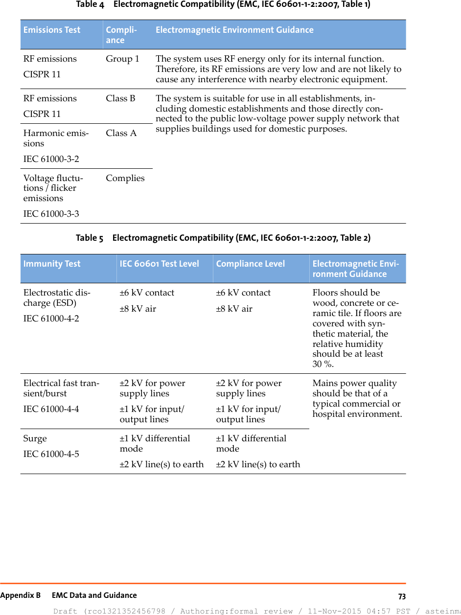
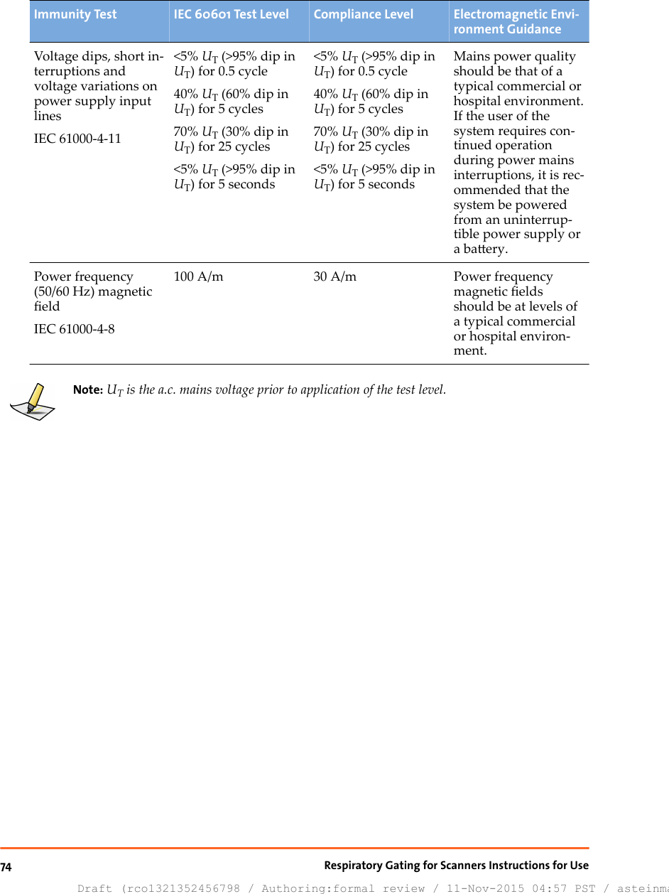
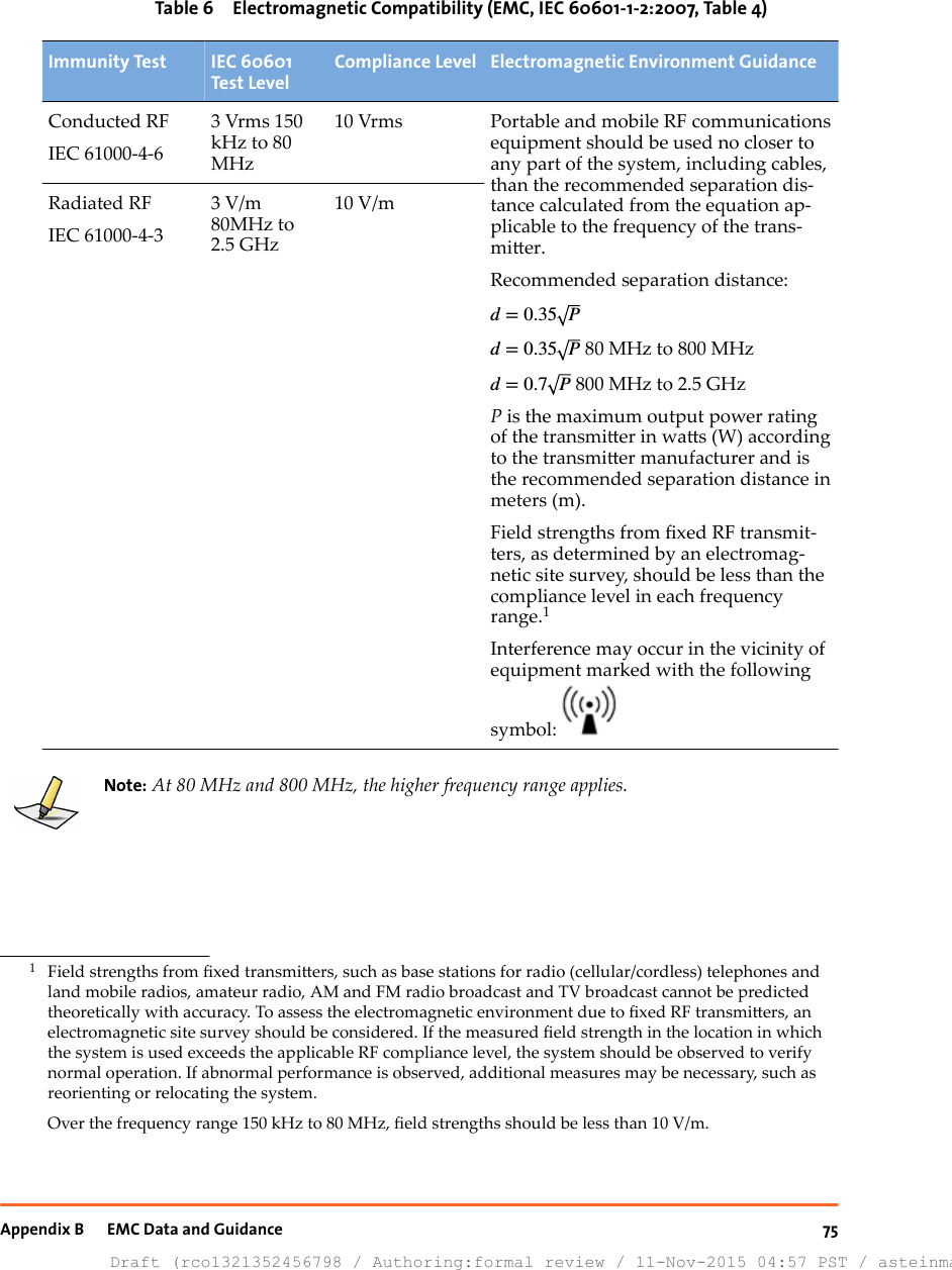
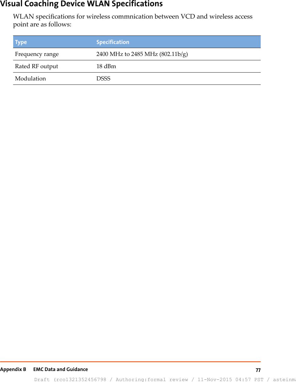
![Note: These guidelines may not apply in all situations. Electromagnetic propagation is aectedby absorption and reection from structures, objects and people.Recommended separation distance between portable and mobile RFcommunications equipment and RGSCThe system is intended for use in an electromagnetic environment in which radiatedRF disturbances are controlled. The customer or the user of the system can helpprevent electromagnetic interference by maintaining a minimum distance betweenportable and mobile RF communications equipment (transmiers) and the system asrecommended below, according to the maximum output power of thecommunications equipment.Table 7 Electromagnetic Compatibility (EMC, IEC 60601-1-2:2007, Table 6)Rated Maximum OutputPower of TransmitterWSeparation Distance According to Frequency of Transmitter [m]150 kHz to 80 MHzd= 0.35 P80 MHz to 800 MHzd= 0.35 P800 MHz to 2.5 GHzd= 0.7 P0.01 0.04 0.04 0.070.1 0.11 0.11 0.221 0.35 0.35 0.7010 1.11 1.11 2.21100 3.50 3.50 7.00For transmiers rated at a maximum output power not listed above, therecommended separation distance d in meters (m) can be estimated using theequation applicable to the frequency of the transmier, where P is the maximumoutput power rating of the transmier in was (W) according to the transmiermanufacturer.Note: At 80 MHz and 800 MHz, the separation distance for the higher frequency rangeapplies.Note: These guidelines may not apply in all situations. Electromagnetic propagation is aectedby absorption and reection from structures, objects and people.76Draft (rco1321352456798 / Authoring:formal review / 11-Nov-2015 04:57 PST / asteinma)Respiratory Gating for Scanners Instructions for Use](https://usermanual.wiki/Varian-Medical-Systems/VCDT711N.UserManual-pdf/User-Guide-2840853-Page-76.png)