Varian Medical Systems VCDT711N Visual Coaching Device (VCD) User Manual UserManual
Varian Medical Systems, Inc. Visual Coaching Device (VCD) UserManual
Contents
- 1. UserManual.pdf
- 2. UserManual_Safety.pdf
UserManual.pdf

Respiratory Gating for
Scanners Instructions
for Use
13485
P1010335-004-C DECEMBER 2015
Draft (rco1321352456798 / Authoring:formal review / 11-Nov-2015 04:57 PST / asteinma)

Document ID P1010335-004-D
Document Title Respiratory Gating for Scanners Instructions for Use
Abstract This document provides reference information and procedures for the following
product:
■Respiratory Gating for Scanners 1.1
This publication is the English-language original.
Manufacturer Varian Medical Systems, Inc.
3100 Hansen Way
Palo Alto, CA 94304-1038
United States of America
European
Authorized
Representative
Varian Medical Systems UK Ltd.
Oncology House
Gatwick Road, Crawley
West Sussex RH10 9RG
United Kingdom
Notice Information in this user guide is subject to change without notice and does not
represent a commitment on the part of Varian. Varian is not liable for errors
contained in this user guide or for incidental or consequential damages in
connection with furnishing or use of this material.
This document contains proprietary information protected by copyright. No part of
this document may be reproduced, translated, or transmied without the express
wrien permission of Varian Medical Systems, Inc.
FDA 21 CFR 820
Quality System
Regulations
(cGMPs)
Varian Medical Systems, Oncology Systems products are designed and
manufactured in accordance with the requirements specied within this federal
regulation.
ISO 13485 Varian Medical Systems, Oncology Systems products are designed and
manufactured in accordance with the requirements specied within the ISO 13485
quality standard.
CE Varian Medical Systems, Oncology Systems products meet the requirements of
Council Directive MDD 93/42/EEC.
EU REACH
SVHC Disclosure
The link to the current EU REACH SVHC disclosure statement can be found at
hp://www.varian.com/us/corporate/legal/reach.html
HIPAA Varian’s products and services are specically designed to include features that help
our customers comply with the Health Insurance Portability and Accountability Act
of 1996 (HIPAA). The software application uses a secure login process, requiring a
user name and password, that supports role-based access. Users are assigned to
groups, each with certain access rights, which may include the ability to edit and
add data or may limit access to data. When a user adds or modies data within the
database, a record is made that includes which data were changed, the user ID, and
the date and time the changes were made. This establishes an audit trail that can be
examined by authorized system administrators.
WHO ICD-O codes and terms used by permission of WHO, from:
■International Classication of Diseases for Oncology, (ICD-O) 3rd edition,
Geneva, World Health Organization, 2000.
2
Draft (rco1321352456798 / Authoring:formal review / 11-Nov-2015 04:57 PST / asteinma)
Respiratory Gating for Scanners Instructions for Use
ICD-10 codes and terms used by permission of WHO, from:
■International Statistical Classication of Diseases and Related Health Problems,
Tenth Revision (ICD-10). Vols 1–3, Geneva, World Health Organization, 1992.
Electronic labeling
This symbol on the label indicates that the Instructions for Use for the
corresponding product are available at www.MyVarian.com. Access the Instructions
for Use in electronic form by logging in with your assigned MyVarian user
credentials.
In compliance with EU Commission Directive No 207/2012, Varian will send EU
customers a free printed copy of the Instructions for Use within 7 days. Use the
“Paper Document Request” form provided on the Varian webpage to order your
copy.
CAUTION: US Federal law restricts this device to sale by or on the
order of a physician.
Trademarks ARIA® is a registered trademark, TrueBeam™, VitalBeam™, Edge™, Clinac™, and
Real-time Position Management™ are trademarks of Varian Medical Systems, Inc.
Microsoft® is a registered trademark of Microsoft Corporation.
All other trademarks or registered trademarks are the property of their respective
owners.
Copyright © 2013–2015 Varian Medical Systems, Inc.
All rights reserved. Produced in Swierland.
Draft (rco1321352456798 / Authoring:formal review / 11-Nov-2015 04:57 PST / asteinma)
3

Contents
CHAPTER 1 INTRODUCTION ...............................................................................................................7
About this Publication ......................................................................................................................................7
About Respiratory Gating for Scanners ....................................................................................................... 7
Intended Use ............................................................................................................................................... 7
Clinical Workflow for Scan and Training Session .............................................................................. 8
Visual Cues ......................................................................................................................................................... 9
Contact Varian Customer Support ............................................................................................................... 9
CHAPTER 2 SAFETY ............................................................................................................................. 11
Safety Overview ................................................................................................................................................11
Symbols Used on Equipment Labels .................................................................................................... 11
Battery Safety ............................................................................................................................................ 13
Maintaining System Integrity ............................................................................................................... 13
Unauthorized or Modified Software ............................................................................................ 13
Unauthorized Hardware ................................................................................................................. 14
Network Impact ........................................................................................................................................14
Third-Party Devices ..................................................................................................................................14
Authorized Maintenance and Service ........................................................................................................ 15
Preventive Maintenance .........................................................................................................................15
System Specifications and Requirements ..................................................................................................15
Electrical Specifications ..........................................................................................................................16
Environmental Specifications ...............................................................................................................16
Environmental Specifications for Transport and Storage .............................................................. 17
Backpointer Laser Specifications ..........................................................................................................17
CHAPTER 3 SYSTEM OVERVIEW ......................................................................................................18
Client Application ............................................................................................................................................18
Scan Workspaces ......................................................................................................................................18
User Interface ............................................................................................................................................19
Hardware Layout ..............................................................................................................................................21
Camera and Reflector Block ..........................................................................................................................22
Camera Controls .......................................................................................................................................23
RGSC Cabinet ................................................................................................................................................... 24
Patch Panel ................................................................................................................................................ 25
Visual Coaching Device (VCD) ......................................................................................................................26
VCD Battery and Charging Station ......................................................................................................27
CHAPTER 4 PREPARE THE EQUIPMENT ........................................................................................ 28
Prepare the Equipment (Overview) ............................................................................................................28
Clean the Reflector Block ..............................................................................................................................28
Cleaning Other Equipment .......................................................................................................................... 28
Start up the System and Log in ................................................................................................................... 29
Mount the Camera on the Couch ............................................................................................................... 29
4
Draft (rco1321352456798 / Authoring:formal review / 11-Nov-2015 04:57 PST / asteinma)
Respiratory Gating for Scanners Instructions for Use

Calibrating the Camera ................................................................................................................................. 30
Calibrate the Camera (Couch-Mounted) ........................................................................................... 30
Verify the Camera is Calibrated (Wall- or Ceiling-Mounted) .........................................................31
Calibrate the Camera (Wall- or Ceiling-Mounted) ........................................................................... 31
Mount the Visual Coaching Device on the Couch ...................................................................................33
Replace and Recharge the Battery of the VCD ................................................................................. 34
Power On/Off of the VCD ...................................................................................................................... 34
Using the VCD in Maintenance Mode ................................................................................................ 35
Resolve Alerts ...................................................................................................................................................36
CHAPTER 5 PREPARE THE SESSION AND THE PATIENT ..............................................................37
Prepare the Session and the Patient (Overview) ..................................................................................... 37
Patient and Session Data .............................................................................................................................. 38
Open or Create a Patient Record ..........................................................................................................38
Entering the Date of Birth .....................................................................................................................39
Open or Create a Session .......................................................................................................................39
Choosing a Type of Scan ................................................................................................................................39
Saving and Loading Default Settings ................................................................................................40
Using the Breathing Predictive Filter ..........................................................................................................41
Enabling Visual Monitoring of Patient Motion ........................................................................................41
Choosing a Coaching Mode ..........................................................................................................................42
Visual Prompt Styles ............................................................................................................................... 42
Using the VCD in Demo Mode .....................................................................................................................44
Place the Reflector Block ...............................................................................................................................45
Learning the Breathing Pattern .................................................................................................................. 46
Baseline ...................................................................................................................................................... 47
Adjusting the Gating Window .....................................................................................................................47
Scaling ................................................................................................................................................................47
CHAPTER 6 ACQUIRE RESPIRATION-SYNCHRONIZED IMAGES ..............................................48
Prepare the Scanner .......................................................................................................................................48
Acquire Images with Prospective Gating ................................................................................................. 48
Acquire Images with Retrospective Gating ............................................................................................. 49
Gating Buttons ................................................................................................................................................49
Monitoring the Respiratory Trace ...............................................................................................................49
Colors Used in The Respiratory Trace Chart ......................................................................................50
Phase Dial ..................................................................................................................................................50
Periodicity Meter ...................................................................................................................................... 51
Monitoring of Patient Motion .............................................................................................................. 52
About Phase Calculation in Real Time ................................................................................................ 53
CHAPTER 7 FINALIZE THE SESSION ................................................................................................55
Finalize the Session (Overview) ................................................................................................................... 55
Reviewing a Session ........................................................................................................................................55
Shifting the Baseline ...............................................................................................................................56
Gating Type for Treatment ............................................................................................................................57
Export for Treatment ...................................................................................................................................... 57
Export for 4D Reconstruction .......................................................................................................................58
Select a Start Time for VXP Export ...................................................................................................... 58
Contents
Draft (rco1321352456798 / Authoring:formal review / 11-Nov-2015 04:57 PST / asteinma)
5

Close the Session ............................................................................................................................................ 59
Shut Down the System ..................................................................................................................................59
APPENDIX A SYSTEM CONFIGURATION ...................................................................................... 60
User Groups .....................................................................................................................................................60
Application .......................................................................................................................................................60
Export ................................................................................................................................................................. 61
Export File Structure and Format ........................................................................................................ 63
Scanner ..............................................................................................................................................................65
VCD ..................................................................................................................................................................... 67
Database ...........................................................................................................................................................68
Archive .............................................................................................................................................................. 69
Camera ..............................................................................................................................................................69
APPENDIX B EMC DATA AND GUIDANCE ..................................................................................... 71
Electromagnetic Compatibility (EMC) ........................................................................................................ 71
Electromagnetic Interference (EMI) .....................................................................................................71
Varian Test Declarations and Guidance ..............................................................................................72
Visual Coaching Device WLAN Specifications ...................................................................................77
INDEX ........................................................................................................................................................ 78
6
Draft (rco1321352456798 / Authoring:formal review / 11-Nov-2015 04:57 PST / asteinma)
Respiratory Gating for Scanners Instructions for Use

Chapter 1 Introduction
About this Publication
This publication is primarily intended for physicists, radiation oncologists, and
radiation therapists, who perform respiration-synchronized image acquisition and
treatment delivery. It describes the most common procedures for using the
Respiratory Gating for Scanners (RGSC) system in clinical use and provides
supporting information.
The appendix has basic information about system conguration for system
administrators.
About Respiratory Gating for Scanners
Respiratory Gating for Scanners (RGSC) is an accessory system to diagnostic imaging
devices. The system is used to observe and record the respiratory motion of a patient
and to transfer this information to the imaging device and to radiation treatment
planners. With integrated audio coaching and optional visual coaching, the system
guides the patient in achieving a more regular and predictable breathing paern
during image acquisition or treatment delivery.
■Imaging devices use respiratory motion information to synchronize their
operation with the respiratory motion of the patient. They either acquire images
based on the trigger signal received from RGSC (prospective mode) or they use the
respiratory motion information for 4D reconstruction after the scanning process
(retrospective mode).
■Radiation treatment planners use respiration-synchronized images to ensure that
the images used for planning and simulation correspond to a know breathing
state that can be detected or reproduced before and during treatment, thereby
enabling beam-on when and only when the patient is in that respiratory state.
Intended Use
For image acquisition, Respiratory Gating for Scanners supports the following
processes:
■Acquire respiratory traces by optically detecting the motion of a reector block,
typically positioned on the abdomen of the patient.
■Acquire respiration-synchronized images in connection with a diagnostic CT or
PET scanner.
Chapter 1 Introduction
Draft (rco1321352456798 / Authoring:formal review / 11-Nov-2015 04:57 PST / asteinma)
7

■Acquire respiration-synchronized 4D images (referred to as retrospectively gated
images) in connection with a diagnostic CT or PET scanner.
To assist respiration-synchronized image acquisition and treatment delivery,
Respiratory Gating for Scanners supports the following processes:
■Assess the amplitude and regularity of the external respiratory motion of the
patient.
■Provide audio and visual coaching to the patient to achieve more regular
respiration.
■Congure three dierent types of gating: phase gating, amplitude gating and
breath-hold gating.
The system uses chest wall or abdominal motion as a surrogate for respiratory
motion of the tumor and other organs and structures within the body. The adequacy
of this surrogate indicator for application to the treatment of any specic patient
condition or setup must be based upon clinical evaluation using CT imaging and
other studies as deemed appropriate. These judgments are the sole responsibility of
qualied medical personnel using the equipment.
Clinical Workflow for Scan and Training Session
In addition to respiration-synchronized image acquisition (scan session), you can
execute training sessions for the following purposes.
■Check whether a patient is able to breathe as needed for respiration-synchronized
image acquisition or treatment delivery.
■Familiarize the patient with coaching techniques.
■Select appropriate options for respiration-synchronized image acquisition.
The training session workow is a subset of the scan session workow, according to
which the chapters in this publication are structured.
Table 1 Clinical Workflow
Step Task Description Scan Training
1Chapter 4 Prepare the Equipment ✓ ✓
2Chapter 5 Prepare the Session and the Patient ✓ ✓
3Chapter 6 Acquire Respiration-Synchronized Images ✓-
4Chapter 7 Finalize the Session ✓-
You can use a training session later to acquire respiration-synchronized images and
nalize the session. If you do, the training session becomes a scan session.
8
Draft (rco1321352456798 / Authoring:formal review / 11-Nov-2015 04:57 PST / asteinma)
Respiratory Gating for Scanners Instructions for Use
Visual Cues
This publication uses the following visual cues to help you nd information:
WARNING: A warning describes actions or conditions that can result in serious injury or
death.
CAUTION: A caution describes hazardous actions or conditions that can result in minor or
moderate injury.
NOTICE: A notice describes actions or conditions that can result in damage to equipment
or loss of data.
Note: A note describes information that may pertain to only some conditions, readers, or sites.
Tip: A tip describes useful but optional information such as a shortcut, reminder, or suggestion,
to help get optimal performance from the equipment or software.
Contact Varian Customer Support
Varian Customer Support is available on the internet, by e-mail, and by telephone.
Support services are available without charge during the initial warranty period.
The MyVarian website provides contact information, product documentation, and
other resources for all Varian products.
1. Go to www.MyVarian.com.
2. Choose an option:
■If you have an account, enter your User login information (email and
password).
■If you do not have an account, click Create New Account and follow the
instructions. Establishing an account may take up to two working days.
3. Click Contact Us at the top of the window to display customer support and
training options, and international e-mail addresses and telephone numbers.
Chapter 1 Introduction
Draft (rco1321352456798 / Authoring:formal review / 11-Nov-2015 04:57 PST / asteinma)
9

4. From the Contact Us page, choose an option:
■Call Varian Medical Systems support using a phone support number for your
geographic area.
■Complete the form corresponding to your request for use on a call with a live
Varian representative; then follow the instructions to complete the remote
connection.
You can order documents by phone, request product or applications support, and
report product-related issues. Links on the MyVarian website navigate to other
support resources for products, services, and education.
5. To nd documents, click Product Documentation.
Online documents in PDF format include customer technical bulletins (CTBs),
manuals, and customer release notes (CRNs).
10
Draft (rco1321352456798 / Authoring:formal review / 11-Nov-2015 04:57 PST / asteinma)
Respiratory Gating for Scanners Instructions for Use
Chapter 2 Safety
Safety Overview
General safety precautions apply to the operation of Respiratory Gating for Scanners
and all associated equipment. Procedures include warnings and cautions describing
a particular hazard.
Where applicable, hardware and software are designed to meet current international
technological and safety standards, for example, IEC for the protection of users and
patients.
The hospital is responsible for establishing emergency and safety procedures to
ensure safe operation and maintenance conditions. Hazards can be encountered, and
risks cannot be ruled out completely. Thus operators must follow instructions and
procedures in this manual to guarantee safety of patients and operators.
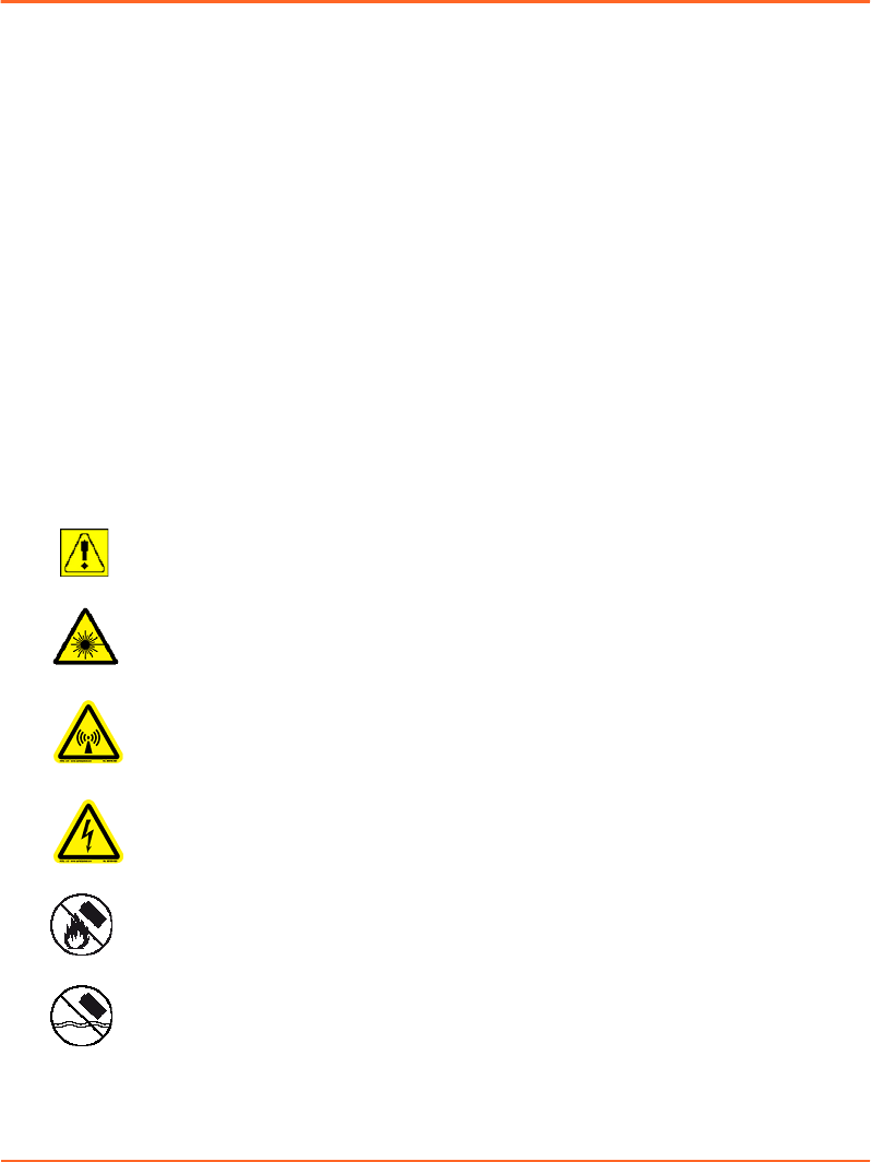
Symbols Used on Equipment Labels
Symbols found on equipment labels have the following meanings:
Potential injury or damage to equipment: Observe safety precautions.
Consult accompanying documents.
Laser radiation: Do not stare into beam; observe laser safety precautions.
Radio frequency radiation: Do not operate this equipment with the covers,
output cable, or interlock cover removed. Radio frequency energy can
cause injury or burns.
Hazardous voltage: Disconnect power before servicing. Contact may cause
electric shock or burn.
Baery safety: Do not expose baery to re.
Baery safety: Do not expose baery to water.
Chapter 2 Safety
Draft (rco1321352456798 / Authoring:formal review / 11-Nov-2015 04:57 PST / asteinma)
11
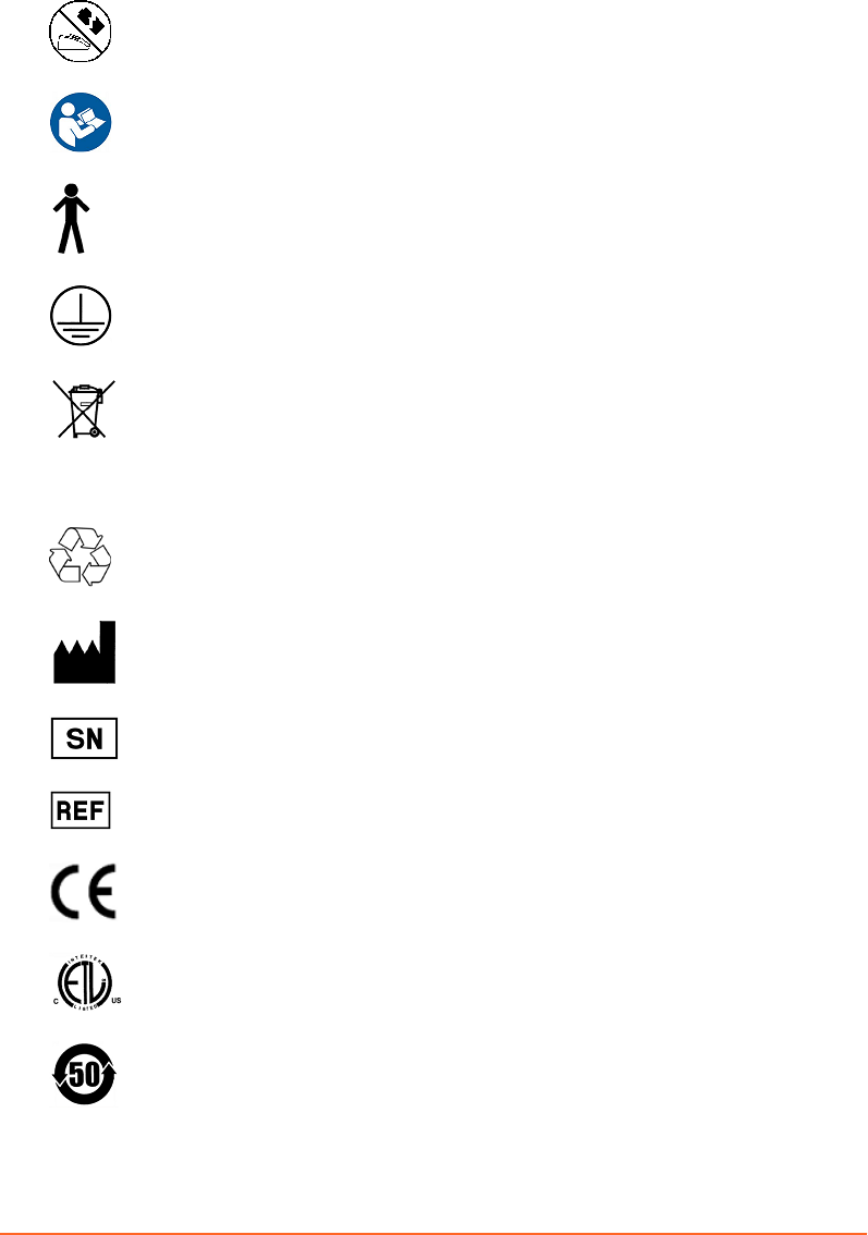
Baery safety: Do not charge baery that may be damaged.
Consult instructions for use. Follow operating instructions.
Type B applied part: This part complies with the specied requirements of
EN 60601-1 to protect against electric shock, particularly regarding
allowable leakage current.
Protective earth (ground): Identied terminals are intended for connection
to earth (ground) for protection against electric shock.
EEE waste: The equipment has been designated as electrical and electronic
equipment (EEE) that is not to be disposed of at the end of its life as
unsorted municipal waste. EEE contains substances that may be hazardous
to human health and to the environment. It must be recovered, reused,
recycled, or otherwise treated and disposed of properly.
Recyclable material: This item can be recycled where correct facilities exist.
Equipment manufacturer: This symbol appears adjacent to the name and
address of the equipment manufacturer.
Serial number: This symbol appears adjacent to the manufacturer’s serial
number.
Reference number: This symbol appears adjacent to the manufacturer’s
reference number (catalog number).
CE conformity: The equipment conforms to the ocial journal of the
European Communities Council Directive 93/42/EEC.
ETL conformity: The equipment conforms to UL STD 60601-1. Certied to
CAN/CSA STD C22.2 No 601.1-M90.
China RoHS conformity: The equipment conforms to People’s Republic of
China Electronic industry standard SJ/T11364-2006.
12
Draft (rco1321352456798 / Authoring:formal review / 11-Nov-2015 04:57 PST / asteinma)
Respiratory Gating for Scanners Instructions for Use
Battery Safety
The baery for the optional Visual Coaching Device (VCD) is a lithium ion baery.
Improper baery use may result in re, explosion, or other hazard. To avoid risk of
injury, follow these instructions for using or storing the baery:
■Only use the baery with the VCD.
■Only use the baery with the dedicated charging station. Use of another charging
station may present a risk of re, explosion, leakage or other hazard.
■Do not disassemble or open, crush, bend or deform, puncture or shred the baery.
■Do not modify the baery or insert foreign objects into the baery.
■Do not immerse the baery in water or other liquids, or expose it to water, re,
explosion, or other hazard.
■Do not short-circuit the baery or allow metallic or conductive objects to contact
the baery terminals.
■Replace the baery only with another VCD baery. Use of any other baery may
risk re, explosion, leakage, or other hazard.
■Promptly dispose of used baeries in accordance with local regulations.
Maintaining System Integrity
Modifying or altering the products, or the software in the products, in any way
constitutes willful infringement of Varian's intellectual property and may endanger
patient safety. Any such modication or alteration will render the system adulterated
under the United States Federal Food, Drug, and Cosmetic Act (or applicable law in
the territory) and could subject the customer or the authorized users to action by the
United States Food and Drug Administration, resulting in seizure, injunction, civil
penalties, or criminal prosecution.
WARNING: Do not modify the hardware or software. Unauthorized modification or
alteration of the hardware or software may endanger patients, operators, or service
personnel.
Unauthorized or Modified Software
Modifying any of the software provided with the system, or installation and use of
any software other than that provided or validated by Varian, can seriously
compromise the integrity of stored data and the performance of operational
applications and can result in uncertain, unreliable, and potentially hazardous
system operation.
Chapter 2 Safety
Draft (rco1321352456798 / Authoring:formal review / 11-Nov-2015 04:57 PST / asteinma)
13

By accepting Varian's Terms and Conditions of Sale, you authorize Varian to remove
any unauthorized software that has been added to, or altered, the system computer,
its operating systems, or the control applications.
To minimize system corruption that may result in serious damage to your system or
in patient harm, follow these instructions:
■Do not modify the system software, including the operating system, control
applications, and data les.
■Do not install software on the system.
■Do not alter the conguration of the system installed by Varian personnel,
including printed circuit boards, control devices, and all seings.
Unauthorized Hardware
Unapproved supplemental devices include the following:
■Any device interfaced to the system using an unauthorized interface.
■Any unapproved device interfaced to the system using authorized interfaces.
Be aware that installation of an unapproved supplemental device has these
consequences:
■May modify or damage the calibration, performance, treatment, or safety
measures installed.
■Will void the Varian warranty.
■Can result in the termination of applicable software licenses.
■Could lead to severe patient injury or death.
Network Impact
The Varian Respiratory Gating for Scanners system is connected to your network,
which may include other equipment. Varian has no control over how the network is
used. It is possible that data trac from the Varian RGSC system could impact the
operation of other equipment and could result in previously unidentied risks to
patients, operators, or third parties. The system owner is responsible for identifying,
analyzing, evaluating, and controlling these risks.
Third-Party Devices
Your site may use one or more non-Varian devices in the scanner room. Be sure to
refer to the documentation that accompanies these devices.
14
Draft (rco1321352456798 / Authoring:formal review / 11-Nov-2015 04:57 PST / asteinma)
Respiratory Gating for Scanners Instructions for Use

Authorized Maintenance and Service
Only service personnel who have received the appropriate maintenance training and
are authorized by the owner are allowed to perform maintenance and service
procedures.
Authorized service personnel must know and follow safety procedures established
for local use by the owner during all service and maintenance procedures. They are
also required to take all precautions necessary to protect themselves, patients, and
other persons from injury, and to protect the equipment from damage.
Preventive Maintenance
Preventive maintenance of the system is very basic and simple and if followed
properly can eliminate potential defects and hazards. Preventive maintenance is
conducted to keep the equipment working and extend the life of the equipment.
Elements of a good preventive maintenance program should include the following:
■Identication of components that may malfunction.
■Establishment of schedules and procedures for routine inspections.
■Periodic testing of equipment for sound functioning.
■Inventory of spare parts.
For more information about general maintenance, contact Varian service personnel.
System Specifications and Requirements
Specications and requirements include electromagnetic, electric, environmental, and
other specications.
Note: Respiratory Gating for Scanners is a medical device that requires special safety
precautions and must be installed and placed in operation in accordance with the published
EMC test declarations and guidance provided.
Related Topics
Electromagnetic Compatibility (EMC) on page 71
Chapter 2 Safety
Draft (rco1321352456798 / Authoring:formal review / 11-Nov-2015 04:57 PST / asteinma)
15
Electrical Specifications
Type Specification
Mode of operation The system is classied as being suitable for continuous con-
nection to the supply mains in the Power Saver mode. This
means that some elements of the system may be connected to
main electrical power even when the system is powered o.
Type of protection against
electric shock
Class I
Degree of protection against
electric shock
Type B
Operating voltage 100–240 V, 50/60 Hz
WARNING: To avoid risk of electric shock, ensure that the equipment is connected to a
supply mains with protective earth.
Environmental Specifications
Type Specification
Humidity 15% to 75% relative, non-condensing humidity
Temperature 15° to 28° C (60° to 80° F)
Degree of safety of applica-
tion in presence of a am‐
mable anesthetic mixture
Unsuitable for use in the presence of a ammable anesthetic
mixture with air, oxygen, or nitrous oxide
Degree of protection against
ingress of water
IPX0 (Ingress Protection Rating) or not waterproof
16
Draft (rco1321352456798 / Authoring:formal review / 11-Nov-2015 04:57 PST / asteinma)
Respiratory Gating for Scanners Instructions for Use
Environmental Specifications for Transport and Storage
Type Specification
Humidity 0% to 50% relative, non-condensing humidity
Temperature −20° to 60° C (−4° to 140° F )
Atmospheric pressure ≤ 15,000 feet elevation
Backpointer Laser Specifications
Type Specification
Laser class II
Wavelength 650–660 nm
Pulse duration Continuous
Power output ≤ 1 mW
Chapter 2 Safety
Draft (rco1321352456798 / Authoring:formal review / 11-Nov-2015 04:57 PST / asteinma)
17
Chapter 3 System Overview
Client Application
The client application is divided into three main areas:
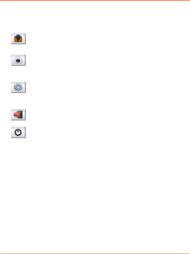
New Scan / Open Scan starts the main workow for dening a new session
and acquiring respiration-synchronized images or for reviewing an existing
scan session.
Verication / Calibration starts the verication and calibration workow
for the camera. For ceiling-mounted or wall-mounted cameras, it guides
you through the acquisition of the reector block positions on the couch in
order to calibrate the camera to the couch top.
Conguration is where administrators can view the conguration of
application, export, scanner, VCD, database, archive, and camera.
In addition, you also nd the following controls:
Log Out / Log In opens the user authentication prompt.
Exit Application closes the application.
Related Topics
Start up the System and Log in on page 29
User Groups on page 60
Scan Workspaces
The application is designed to facilitate navigation along the clinical workow. While
it guides you from workspace to workspace, you can jump back or forth at any time.
The typical workow for respiration-synchronized image acquisition guides you
through the workspaces as follows:
1. Initiate the workow under New Scan / Open Scan.
2. Create or open a patient record under Patient.
3. Create or open a session under Session.
18
Draft (rco1321352456798 / Authoring:formal review / 11-Nov-2015 04:57 PST / asteinma)
Respiratory Gating for Scanners Instructions for Use
4. Specify scan seings under Seings.
■Select a type of scan.
■Specify gating and coaching options.
5. Acquire respiration-synchronized images under Scan.
■Actively coach the patient: Start and stop coaching.
■Adjust the gating thresholds.
■Record the breathing.
■Monitor the breathing.
■Turn gating on and o.
6. Review a session under Review.
■Review and apply the calculated baseline shift.
■Review and export data for 4D reconstruction.
■Review and export data for treatment delivery.
■Close the session.
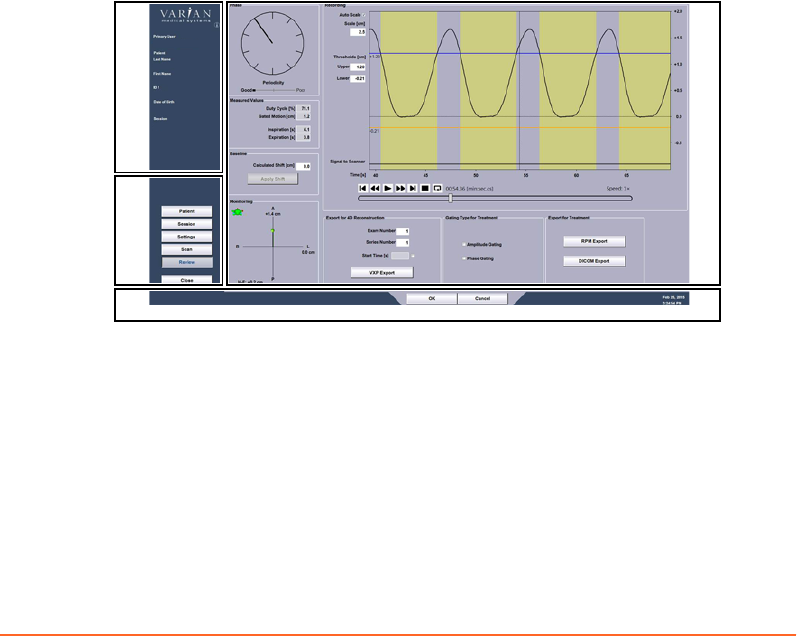
User Interface
The user interface is divided into the following sections:
1
2
3
4
1. Info Panel
2. Workflow Panel
3. Control Bar
4. Workspace Panel
Figure 1 User Interface
Chapter 3 System Overview
Draft (rco1321352456798 / Authoring:formal review / 11-Nov-2015 04:57 PST / asteinma)
19

Info panel The info panel displays the name of the current user, the date of
birth, rst name, and last name of the patient, and the patient ID.
After opening a session, the info panel also displays the name of the
current session.
The info buon i under the Varian logo opens the About RGSC
window. It provides information about the operating system and
the application.
If there are any pending alerts (RGSC Messages) for the system, an
orange buon appears. The buon provides information about an
alert or opens a dialog box.
Workow
panel
The workow panel accommodates the buons for navigating
between workspaces. There is one buon for each workspace.
Workspace buons are active according to user rights and
workow.
Workspace
panel
Pressing a buon in the workow panel opens the corresponding
workspace in the workspace panel. A workspace typically consists
of one panel, but it can include tabs.
Control bar The control bar accommodates conrmation and cancellation
buons. It also displays the current date and time, and workow‐
specic messages.
20
Draft (rco1321352456798 / Authoring:formal review / 11-Nov-2015 04:57 PST / asteinma)
Respiratory Gating for Scanners Instructions for Use
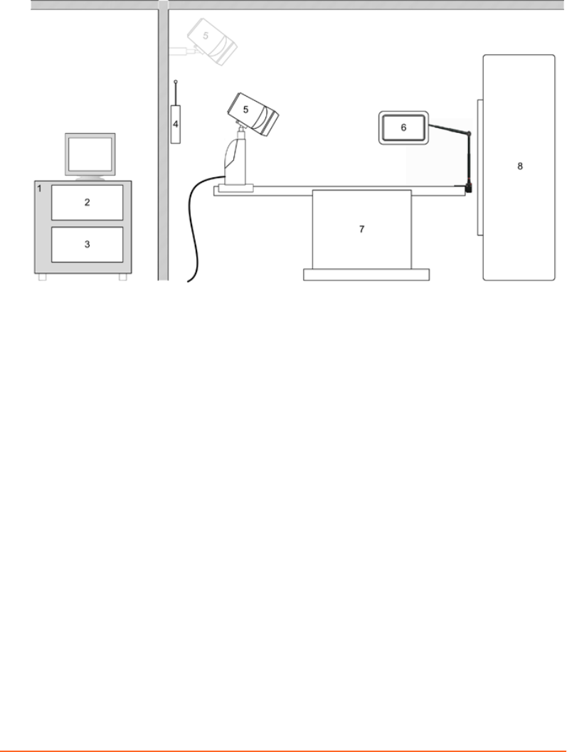
Hardware Layout
1. RGSC Cabinet
2. Workstation Unit
3. Real-Time Unit
4. Wireless Access Point (optional)
5. Camera (on couch, wall, or ceiling)
6. Visual Coaching Device (optional)
7. Couch
8. Scanner
Figure 2 Hardware Layout
Hardware components are installed in two main areas: the control room and the
scanner room. The illustration shows the location of the main hardware components.
The RGSC cabinet (including Workstation Unit and Real-Time Unit) and other
computer peripherals are installed in the control room. The Real-Time Unit controls
the interface to the scanner, camera and wireless access point in the scanner room.
The camera can be mounted in a xed position on the wall or ceiling, or as a mobile
version on the couch with a dedicated couch mount.
Chapter 3 System Overview
Draft (rco1321352456798 / Authoring:formal review / 11-Nov-2015 04:57 PST / asteinma)
21
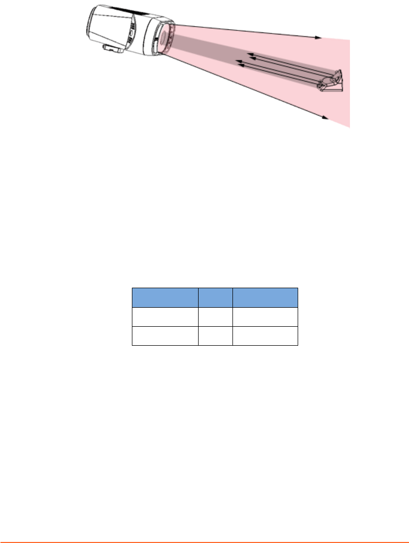
Camera and Reflector Block
Figure 3 Infrared Tracking Concept
Supported Tracking Distances
The camera delivers live video image data by tracking an infrared spectrum. It emits
infrared light and detects the reections from the passive markers of the reector
block. This allows identifying the exact position and orientation of the reector block
and tracking the respiratory motion. The camera is optimized to provide a high-
contrast image of the reector block markers.
Depending on the camera mount (couch, ceiling, or wall), one of the following
camera lenses is in use:
Camera Mount Lens Distance
Wall or ceiling 25 mm 2500-5600 mm
Couch 12 mm 1000-2500 mm
22
Draft (rco1321352456798 / Authoring:formal review / 11-Nov-2015 04:57 PST / asteinma)
Respiratory Gating for Scanners Instructions for Use
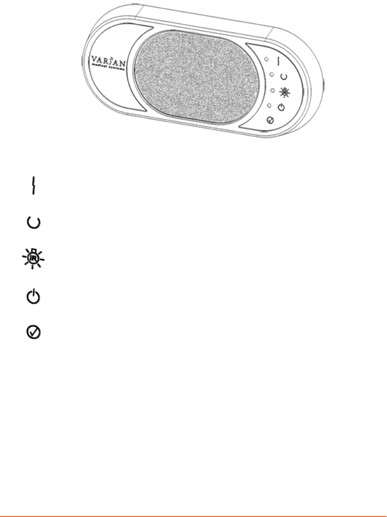
Camera Controls
The following controls are available on the front of the camera.
Connection Error indicates that there is no Ethernet connection between
camera and the Real-Time Unit.
Tool Detected indicates when reector block is detected by the camera, the
reported position is within the dened volume and acquisition is started.
IR Illumination indicates that infrared illumination is ON.
Power indicates that power is ON.
Conrm (buon) conrms the calibration process and can be used as an
alternative to the OK buon in the calibration workspace.
Chapter 3 System Overview
Draft (rco1321352456798 / Authoring:formal review / 11-Nov-2015 04:57 PST / asteinma)
23
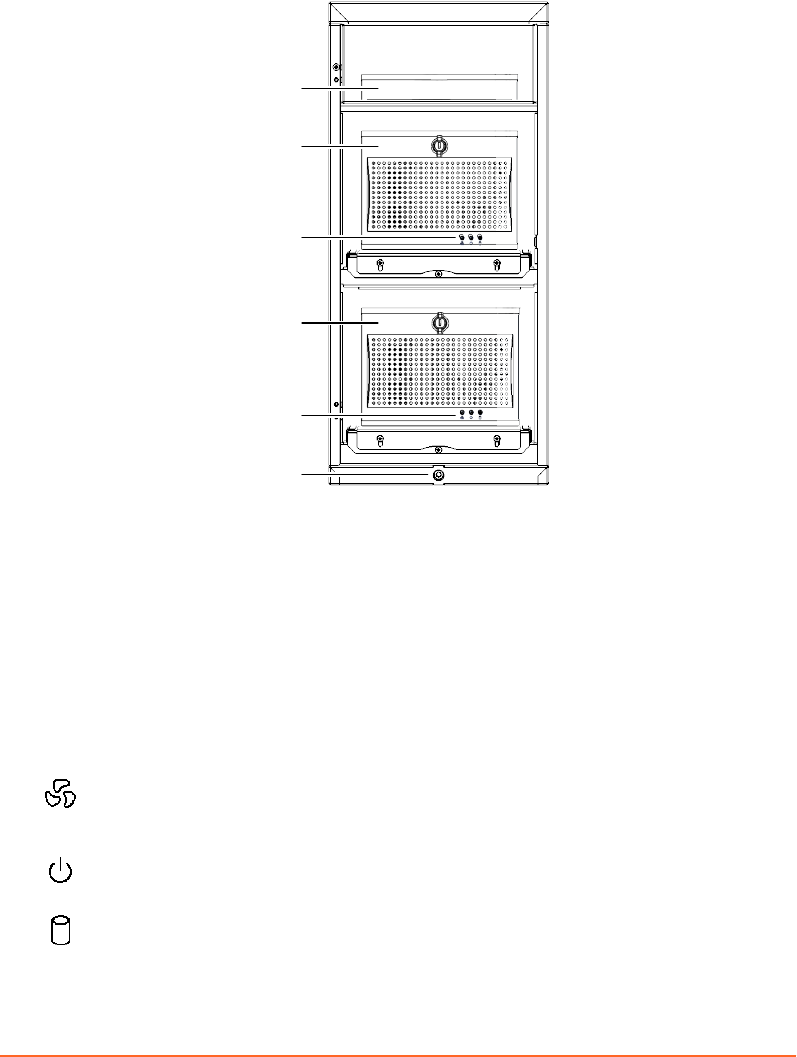
RGSC Cabinet
1
2
3
4
3
5
1. Firewall and Network Switch
2. Workstation Unit
3. Status Indicators
4. Real-Time Unit
5. Height Adjustment (extract/retract
wheels)
Figure 4 Cabinet
The RGSC cabinet includes two processor units. The Workstation Unit runs the
software application of Respiratory Gating for Scanners, the Real-Time Unit is
responsible for real-time image data processing.
The Workstation Unit and the Real-Time Unit use the same three status indicators
On the Workstation Unit, red indicates a fan error is active.
On the Real-Time Unit, the status indicator is not in use.
Blue indicates that power is on.
On the Workstation Unit, white indicates drive activity (SDD).
On the Real-Time Unit, white indicates ash card activity.
24
Draft (rco1321352456798 / Authoring:formal review / 11-Nov-2015 04:57 PST / asteinma)
Respiratory Gating for Scanners Instructions for Use
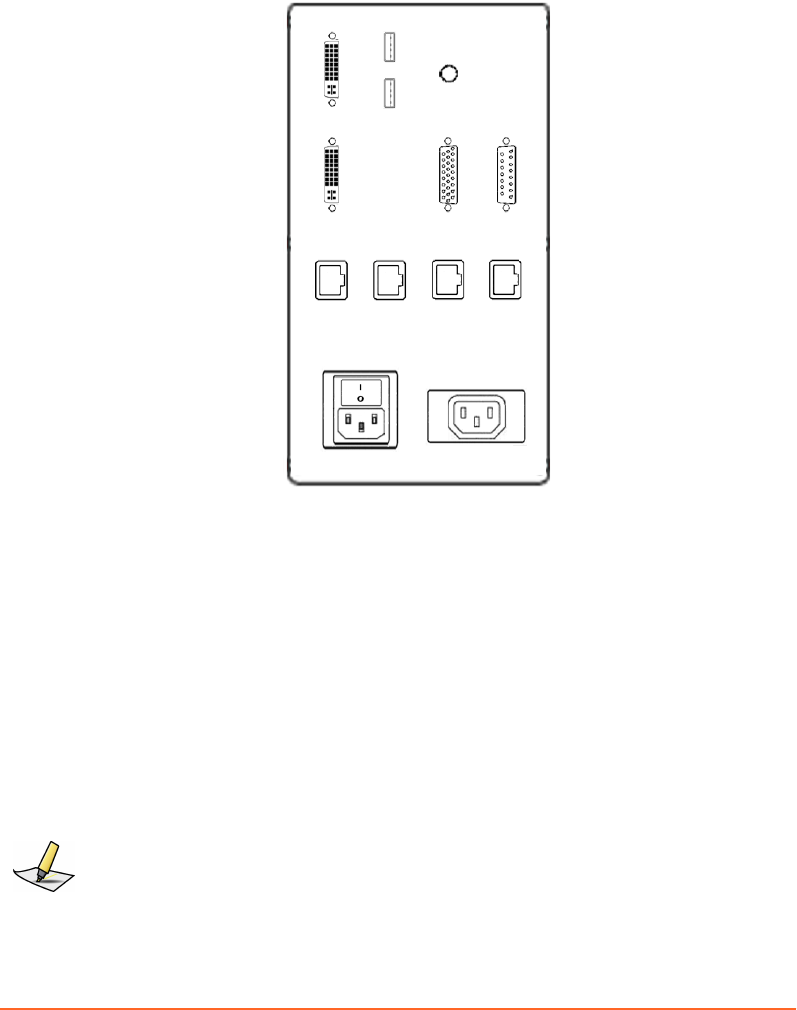
Patch Panel
All interfaces to the hardware are connected through the patch panel located at the
back of the cabinet.
J3
J5
J6
J4
J13
J12 J11 J10 J8
J1
J2
J9 J7
Supply Ratings
100-240V, 50-60Hz, 240VA
100-240V, 50-60Hz
J3 DVI Monitor Output (primary) J12 Service Port
J13 DVI Monitor Output (secondary) J11 Hospital Network
J5 USB 1 J10 Wireless Access Point
J6 USB 2 J8 Camera Network
J4 Audio Output J1 Main Power Inlet and Switch
J9 Scanner I/F J2 Monitor Power Outlet
J7 Camera I/F
Figure 5 Patch Panel
Note: Use the monitor power outlet only for the monitor provided with the system. Use the
audio output to connect a speaker system and enable audio coaching.
Chapter 3 System Overview
Draft (rco1321352456798 / Authoring:formal review / 11-Nov-2015 04:57 PST / asteinma)
25
Visual Coaching Device (VCD)
The Visual Coaching Device (VCD) is an optional accessory used in the scanner room
to help the patient maintain a steady breathing paern. Visual coaching gives visual
feedback to the patient by displaying the current position and the targeted position
of breathing. Visual coaching can increase the accuracy of the absolute position of the
breathing process and the relative position within the breathing period.
The VCD operates in combination with following other components:
RGSC
application
The client application starts tracking on the Real-Time Unit,
congures the coaching seings, and starts/stops the visual
prompt on the VCD.
Real-Time Unit The Real-Time Unit processes image data from the camera to
calculate the position and orientation of the reector block. It
then distributes the data to the VCD and the workstation unit.
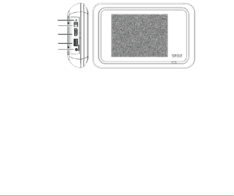
The VCD includes various connectors, all located on the left side behind a cover.
1
4
2
3
5
1. Status LED (lit when booting or ready)
2. External DC Power Supply
3. Video Output
4. USB
5. Audio Output (no function)
Figure 6 VCD Connectors
The external power supply used to power the charging station can also be connected
to the VCD. This connection may be required when no baery is available or
suciently charged.
The video output can be used to connect to an external monitor, projector or goggles.
The USB port can be used as power supply for external goggles (must be turned on
and o in the VCD seings).
26
Draft (rco1321352456798 / Authoring:formal review / 11-Nov-2015 04:57 PST / asteinma)
Respiratory Gating for Scanners Instructions for Use
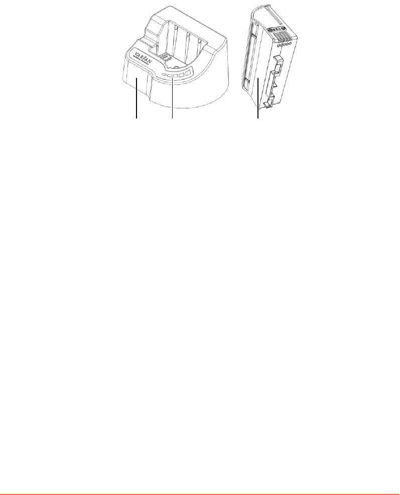
VCD Battery and Charging Station
To ensure that one baery is always charged and available, the VCD comes with an
additional baery and a charging station. The charging station indicates the status of
charging.
1 2 3
1. Charging Station
2. Charging Status Indicators
3. Battery
Figure 7 VCD Battery and Charging Station
Dierent colors indicate the charging status:
Red An error occurred. The red indicator is always accompanied by a green
indicator that identies the type of error.
■If the rst indicator from the left is green, the connection is faulty.
■If the second indicator from the left is green, the temperature of the
baery is too high or low (> 50°C or < 10°C).
■If the third indicator from the left is green, an undened error occurred.
To resolve the error, remove and reinsert the baery. If this does not
resolve the error, replace the baery as it is likely damaged.
■If the fourth indicator from the left is green, the power supply is faulty.
Orange No baery is in the charging station.
Green The baery is charging. The number of green indicators increases while
the baery charges. The ashing indicator represents the current charging
level. When the baery is charged, all indicators are lit (ashing stops).
Related Topics
Replace and Recharge the Baery of the VCD on page 34
Chapter 3 System Overview
Draft (rco1321352456798 / Authoring:formal review / 11-Nov-2015 04:57 PST / asteinma)
27

Chapter 4 Prepare the Equipment
Prepare the Equipment (Overview)
This document describes use of Respiratory Gating for Scanners, but not its
installation and conguration. Such tasks must be performed by trained Varian
personnel only. For information about conguration seings, refer to the appendix.
1. Clean the reector block.
2. Clean other equipment.
3. Start and log in to the application.
4. If the camera is couch-mounted, mount it.
5. If necessary, verify the calibration of the camera or calibrate it or both.
6. If available, mount and switch on the Visual Coaching Device (VCD).
Make sure the baery is loaded.
7. Review and resolve any remaining alerts (RGSC Messages).
Proceed to prepare the patient and the session.
Clean the Reflector Block
Before each new patient, take special care to clean and inspect the reector block.
1. Spray the reector block with a 70% to 90% isopropyl alcohol solution.
2. Wipe with white sterile cloth.
3. Allow to dry according to the manufacturer's instructions.
4. Inspect for damage.
Cleaning Other Equipment
Unlike the reector block, which requires special care, clean any other equipment
only when needed:
■Use only the following cleaning solutions and follow the instructions of the
manufacturer:
■Isotropy alcohol
■CIDEX PLUS
■Soap and Water (do not use to clean VCD couch mount)
■Mild spray cleaner
28
Draft (rco1321352456798 / Authoring:formal review / 11-Nov-2015 04:57 PST / asteinma)
Respiratory Gating for Scanners Instructions for Use
■Diluted chlorine bleach
■Do not spray cleaning solutions. Pour solutions onto a cloth and wipe surfaces
clean.
■Wipe o excess cleaning solution.
If you have questions about cleaning with chemical solutions, contact an authorized
Varian representative.
Start up the System and Log in
1. Switch on the workstation and log in to Windows.
After logging in to Windows, the application initiates automatically.
2. Log in to the application.
Note: Your credentials for Windows and Respiratory Gating for Scanners are not
synchronized.
Related Topics
Client Application on page 18
User Groups on page 60
Mount the Camera on the Couch
The following instructions only apply if the system has a couch-mounted camera.
You can mount the camera before or after starting up the system. If the system is
running, but the camera is not mounted, the application states Camera not ready.
1. Engage the camera stand with the docking unit on the couch top.
CAUTION: To avoid situations where the camera falls off the couch or on the patient,
ensure that the locking mechanism is fully engaged.
2. If unplugged, plug the camera cable into the stand and secure the plug with the
twist lock.
CAUTION: To avoid situations where the cable disconnects during couch movements or
scanning, ensure that the locking mechanism of the cable connector is fully engaged
(snapped in).
Chapter 4 Prepare the Equipment
Draft (rco1321352456798 / Authoring:formal review / 11-Nov-2015 04:57 PST / asteinma)
29
Up to a certain degree, the system is capable of detecting whether the camera is
mounted correctly and will state Camera misaligned if a mismatch is detected.
Nonetheless, an additional manual check is required.
Calibrating the Camera
Calibration of the camera is critical to the acquisition of reference data. If the
equipment is not calibrated correctly, a discrepancy can occur between actual
positions and positions as determined by the system.
Access to the Calibration workspace requires that the system be connected and
running properly, and that you have the necessary access rights.
WARNING: The camera must be calibrated after installation and after its position has
changed. If the camera has been moved and the calibration is no longer correct, the
acquired data will be incorrect. Ensure that the camera is calibrated after being moved.
Verify periodically.
Calibrate the Camera (Couch-Mounted)
The following instructions only apply if the system has a couch-mounted camera.
Calibrate the camera periodically or when prompted by the system.
1. Open the Calibration workspace.
2. Place the reector block in the eld of view of the camera on the couch top,
aligned with the couch axes.
Use the laser system of the scanner for orientation.
3. Click OK.
Successful calibration is conrmed with the calibration result Calibration
passed.
30
Draft (rco1321352456798 / Authoring:formal review / 11-Nov-2015 04:57 PST / asteinma)
Respiratory Gating for Scanners Instructions for Use

Verify the Camera is Calibrated (Wall- or Ceiling-Mounted)
The following instructions only apply if the system has a wall-mounted or ceiling-
mounted camera.
Verify that the camera is calibrated under the following circumstances:
■Daily (recommended)
■When prompted by the system
1. To access the verication wizard, choose Verication / Calibration >
Verication.
2. Place the reector block in the isocenter of the scanner.
Use the laser system of the scanner for orientation.
3. Click OK.
The system automatically calculates reector block positions. After completion, the
result appears under Progress.
■If verication was successful, Verication Results states Verification
passed.
■If verication was unsuccessful, Verication Results states Verification
failed.
If verication failed, ensure that no reective body interferes with the IR signal
from the camera. To prevent reections from the couch top, place the calibration
board under the reector block. Verify the correct alignment of the reector block.
If verication fails several times, perform a new calibration procedure.
Calibrate the Camera (Wall- or Ceiling-Mounted)
The following instructions only apply if the system has a wall-mounted or ceiling-
mounted camera.
Calibrate the camera under the following circumstances:
■If calibration verication failed
■After repositioning the camera
■After updating the software
■Periodically or when prompted by the system
1. To access the calibration wizard, choose Verication / Calibration > Calibration.
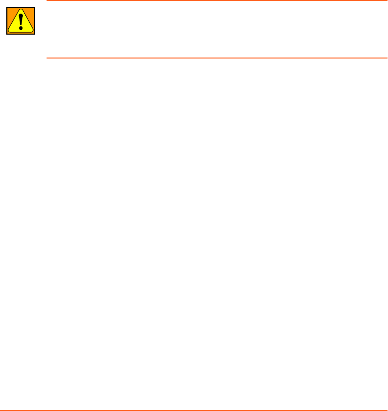
2. Place the calibration board with position 1 in the isocenter of the scanner.
Chapter 4 Prepare the Equipment
Draft (rco1321352456798 / Authoring:formal review / 11-Nov-2015 04:57 PST / asteinma)
31
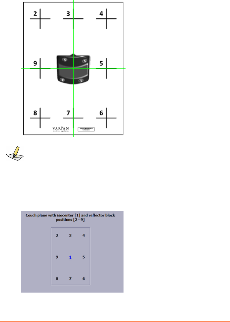
3. Place the reector block on position 1 on the calibration board.
Note: This position will be used for the verication process.
A correct alignment of the reector block in the isocenter is essential for the entire calibration
process.
4. Press the Conrm buon on the camera or click OK in the application.
5. Move the reector block on the calibration board, following the chart displayed
at the boom of the calibration display. After each position (2 to 9), press the
Conrm buon on the camera or click OK in the application.
32
Draft (rco1321352456798 / Authoring:formal review / 11-Nov-2015 04:57 PST / asteinma)
Respiratory Gating for Scanners Instructions for Use

The number of each step is highlighted successively through the positioning
process.
During calibration, the position of the reector block is displayed as follows:
■If the system was already calibrated, it shows coordinates relative to the
calibrated isocenter position.
■If this is the rst calibration of the system, no coordinates are displayed.
Instead Valid or Not valid signals.
At the end of the calibration, the system calculates the plane values.
■If calibration is successful, Progress states Plane calculation is finished.
■If calibration is not successful, an alert pops up and states The calibration
of the couch plane failed. Investigate and resolve possible causes, then
repeat the calibration process. Possible causes can be the following:
■Reections from other objects than the reector block (such as, couch top)
interfere with the IR signal of the camera.
■The distance between center position and any other position on the calibration
board is too small (< 10 cm).
■The orientation of the reector block at center position of the calibration board
is not valid.
■The camera is not installed properly (wrong orientation, wrong angle to couch
plane).
■The surface on which the calibration is performed is not at enough.
Mount the Visual Coaching Device on the Couch
The following instructions only apply if the system has a couch-mounted Visual
Coaching Device (VCD).
1. Aach the VCD couch mount base unit to the couch.
2. Aach the VCD on the telescope to the couch mount base unit.
CAUTION: If the Visual Coaching Device is not properly mounted, it can fall on the
patient causing injury. When using the Visual Coaching Device, always verify that the
base part of the couch mount is correctly attached and locked to the scanner couch top
and that the telescopic arm is correctly inserted and locked in the base part.
3. Switch on the VCD.
4. Check the baery status and replace the baery if necessary.
5. Check the network connection.
6. If you are using video goggles, connect them to the video output terminal of the
VCD.
Chapter 4 Prepare the Equipment
Draft (rco1321352456798 / Authoring:formal review / 11-Nov-2015 04:57 PST / asteinma)
33
Replace and Recharge the Battery of the VCD
To avoid an unexpected shutdown of the VCD during image acquisition, check the
baery status of the VCD before each use.
Note: The Visual Coaching Device must be running properly during the entire scan to ensure
that the patient is breathing periodically. Failure of coaching during acquisition can lead to
irregular breathing. The scan may have to be repeated.
1. Check the baery status on the VCD itself or in the desktop application
■On the VCD, check the baery icon in the status bar. Alternatively, enter the
maintenance mode (draw a capital M on the touchscreen), then choose the
Baery tab.
■In the desktop application, hover over the baery symbol in the coaching
view. Alternatively, choose Conguration > VCD.
2. If necessary, replace the baery with a recharged one.
If you fail to replace the baery in time, the VCD shuts down without warning.
3. Connect the dedicated charging station to the power supply and insert the empty
baery for recharging.
CAUTION: Incorrect voltage applied to the charging station can cause overheating or
fire. Connect only the power supply provided by Varian (P/N B503887R01) to the Visual
Coaching Device or to the charging station.
Related Topics
VCD Baery and Charging Station on page 27
Power On/Off of the VCD
The power buon of the VCD has the following functions:
■Press short: The VCD boots, goes to sleep, or wakes up.
■Press long: The VCD announces that it is shuing down (normal shutdown). If
you keep the buon pressed for more than 5 seconds, the VCD forces a hard
shutdown.
34
Draft (rco1321352456798 / Authoring:formal review / 11-Nov-2015 04:57 PST / asteinma)
Respiratory Gating for Scanners Instructions for Use
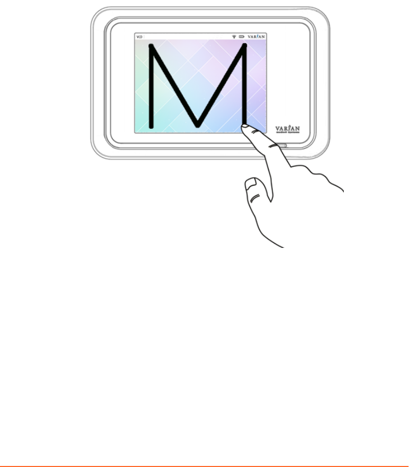
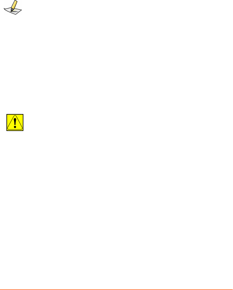
Using the VCD in Maintenance Mode
The VCD includes a maintenance mode to view the current state of the baery, to
select or check the network, and to adjust display seings.
■To enter the maintenance mode from the home screen, draw a capital M on the
touchscreen.
■To return to the home screen, touch the arrow symbol at the top left of the
touchscreen.
Figure 8 Enter Maintenance Mode of VCD
Related Topics
Using the VCD in Demo Mode on page 44
Chapter 4 Prepare the Equipment
Draft (rco1321352456798 / Authoring:formal review / 11-Nov-2015 04:57 PST / asteinma)
35

Resolve Alerts
If the system has any pending alerts (RGSC Messages), the info panel of the
application displays an orange buon labeled Functionality limited. Alerts can be
error messages, warnings and informational messages.
1. To open the RGSC Messages dialog box, click Functionality limited.
2. Resolve the cause of the rst alert (details and required actions are stated), then
click it for conrmation.
3. Resolve the cause of the next alert, then click it for conrmation.
4. Repeat this step until all alerts are resolved and the OK buon is active.
5. Click OK.
36
Draft (rco1321352456798 / Authoring:formal review / 11-Nov-2015 04:57 PST / asteinma)
Respiratory Gating for Scanners Instructions for Use

Chapter 5 Prepare the Session and the Patient
Prepare the Session and the Patient (Overview)
The following instructions assume that you have prepared the equipment.
1. Open the patient record or create a new one.
2. Open a session or create a new one.
3. Select a type of scan (gating type), if applicable as prescribed.
■To scan throughout the entire respiratory trace and reconstruct a 4D scan,
choose 4D Scan.
■To scan only while the respiratory trace is within the phase gating window
(1 scanner rotation per window), choose Phase Gating.
■To scan only while the respiratory trace is within the amplitude gating
window (1 scanner rotation per window), choose Amplitude Gating.
■To scan only while the respiratory trace is held within the breath-hold gating
window (x scanner rotations per window), choose Breath-hold.
4. If necessary, adjust the default seings of the selected type of scan.
■To detect non-periodic breathing and prevent image acquisition if necessary,
specify the breathing predictive lter.
■For image acquisition with breath-hold gating, specify the delay with which
to acquire scans after reaching the gating window.
■For image acquisition with phase gating, specify the thresholds of the gating
window in % relative to the inspiration peak (0% or 100%) and the expiration
peak (50%).
■For image acquisition with amplitude gating and breath-hold gating, specify
the thresholds of the gating window in cm relative to the baseline determined
during the learning process.
5. If necessary, enable visual patient motion monitoring.
6. Enable and congure coaching.
■For audio coaching, select the language.
■For visual coaching, select and congure a visual prompt style.
You can set the motion range and coaching speed manually or allow the system
to determine them during the subsequent learning process.
7. Instruct the patient on how coaching works and on how to breathe with
assistance of the VCD (demo mode).
Chapter 5 Prepare the Session and the Patient
Draft (rco1321352456798 / Authoring:formal review / 11-Nov-2015 04:57 PST / asteinma)
37
8. Set up the patient on the couch.
WARNING: A mismatch between the patient on the couch and the patient data on
display can lead to the storage of the wrong gating data for that patient. Check the
patient details carefully against the patient on the couch to verify the correct patient is
selected in the system.
WARNING: RGSC supports only Head First Supine (HFS). If the patient orientation is not
HFS, an inconsistency will result of the reference session with the delivery system
treatment session. Ensure that only HFS is applied.
9. Verify that the patient sees the VCD.
10. Verify that the reector block is clean and undamaged.
11. Place the reector block on the patient.
12. Instruct the patient to breathe regularly.
13. Start the learning process.
The system starts to track four cycles of the respiratory trace. Based on the
learning process, the system determines the baseline (average expiration peaks).
If enabled, the system also determines the motion range and coaching speed.
Alternatively, both can be changed manually.
14. If necessary, restart the learning process.
The position of thresholds relative to their reference may change as a result.
15. If necessary, adjust the gating seings and coaching seings.
Depending on the purpose of the session, proceed as follows:
■If the session is intended for training only, help up the patient, and close the
session.
■If the session is intended for image acquisition, proceed to prepare the scanner
and acquire respiration-synchronized images.
Patient and Session Data
Depending on the system conguration, the system saves and retrieves patient and
session data either in database mode or le mode.
When you open the Patient workspace in le mode, it lists the patients that are in the
system. In database mode, the list is empty.
Open or Create a Patient Record
1. To clear any previous entries and start a new search, click Clear.
2. Enter search criteria in the available text boxes.
38
Draft (rco1321352456798 / Authoring:formal review / 11-Nov-2015 04:57 PST / asteinma)
Respiratory Gating for Scanners Instructions for Use

3. Depending on the local conguration, do one of the following:
■Click Find.
■Click Filter.
4. Do one of the following:
■If the patient appears in the list, select it and click Open, or double-click it.
■If the patient does not appear in the list, enter the mandatory data and click
Create.
Mandatory entries are highlighted.
Entering the Date of Birth
When you create a new patient record and go to Date of Birth, the current date
appears. You can then adjust the date in dierent ways.
■Click the calendar symbol and select the correct date from the calendar.
■Adjust the date via keyboard.
■To move between day, month, and year, use the division key (on the numeric
keypad) or the left and right arrow keys.
■To adjust day, month, and year, enter the numeric value or use the up and
down arrow keys.
Open or Create a Session
Before you can open or create a session, you must open a patient record.
The Session workspace lists the sessions (training and scan) that the patient has had
in the past. You can create a new session from scratch or use an existing session of the
same gating type as basis.
Depending on your approach, do one of the following:
■To create a new session from scratch, enter a unique session name and click
Create.
■To create a new session based on a previous session, select an existing session and
click Open, or double-click an existing session.
The session opens in the Review workspace. To create a new session, change to
the Scan workspace, make adjustments as needed, and click Record. The system
prompts you to give the session a new name.
Choosing a Type of Scan
Before you can choose a type of scan, you must open or create a session.
Chapter 5 Prepare the Session and the Patient
Draft (rco1321352456798 / Authoring:formal review / 11-Nov-2015 04:57 PST / asteinma)
39
Retrospective Scan
4D
Scan
This type of gating is intended for continuous acquisition of motion data to
reconstruct a 4D scan retrospectively. Depending on the scanner model on
site, the gating system sends trigger signals at a predened phase (0° by
default). Once the scan is complete, the scanner synchronizes the
respiratory trace with the acquired image data to generate the 4D image
set.
Prospective Scans
Phase
Gating
This type of gating is intended for phase-gated image acquisition of a
free-breathing patient. With phase gating, you dene the gating
thresholds based on phase values. The gating system sends a trigger
signal to the scanner when the respiratory trace enters the gating
window. This allows acquiring a set of images at a specic couch
position. Once acquisition at a couch position is complete, the
scanner moves to the next position and waits for the next trigger
signal.
Amplitude
Gating
This type of gating is intended for amplitude-gated image
acquisition of a free-breathing patient. With amplitude gating, you
dene the gating thresholds based on amplitude values. The gating
system sends a trigger signal to the scanner when the respiratory
trace enters the gating window. This allows acquiring a set of images
at a specic couch position. Once acquisition at a couch position is
complete, the scanner moves to the next position and waits for the
next trigger signal.
Breath-hold
Gating
This type of gating is intended for gated image acquisition of a
patient able to hold breath. With breath-hold gating, you dene the
gating thresholds based on amplitude values. Depending on the
scanner, the gating system sends one or several trigger signals to the
scanner for as long as the respiratory trace is within the gating
window. During that period, the scanner acquires sets of images,
moving from couch position to couch position.
Saving and Loading Default Settings
You can save and load specic gating seings as default for reuse on other scans.
Save Gating Default Seings saves the current seings as default seings
for a particular type of gating.
40
Draft (rco1321352456798 / Authoring:formal review / 11-Nov-2015 04:57 PST / asteinma)
Respiratory Gating for Scanners Instructions for Use

Click the arrow to the right on the buon to choose the applicable type.
Load Gating Default Seings loads the default seings for a particular
type of gating. Once the site‐specic default seings are saved, default
seings are automatically loaded for each new scan with the same type of
gating.
Click the arrow to the right on the buon to choose the applicable type.
Using the Breathing Predictive Filter
For image acquisition with amplitude gating, phase gating, or for 4D reconstruction,
the breathing predictive lter monitors and predicts the breathing paern of the
patient to protect against misapplied radiation. The breathing predictive lter
calculates a periodicity value by comparing phase and amplitude values of the latest
breathing sample with the previous breathing paern of the patient. If the periodicity
values fall below the dened range, the system stops triggering scans. You can adjust
the sensitivity of the lter to detect non-periodicity.
100% means maximum sensitivity. 0% means the lter is disabled. The following
values are recommendations:
■For image acquisition with amplitude gating and phase gating, use 20%.
■For image acquisition for 4D reconstruction, use 5%.
For images acquired with breath-hold gating, the lter is disabled by default.
Related Topics
Periodicity Meter on page 51
Enabling Visual Monitoring of Patient Motion
Select Enable Visual Patient Motion Monitoring to continuously verify if the
reector block position is within the learned range. If the reector block moves out of
the learned range, the color of the ball (representing respiratory motion) changes.
This monitoring is purely visual and has no eect on any other seings.
Related Topics
Monitoring of Patient Motion on page 52
Chapter 5 Prepare the Session and the Patient
Draft (rco1321352456798 / Authoring:formal review / 11-Nov-2015 04:57 PST / asteinma)
41
Choosing a Coaching Mode
To access the coaching seings, open the Coaching tab. Based on patient
requirements, you can choose either audio or visual coaching or both. If you use
audio and visual coaching together, consider the audio coaching oset (dened in the
application seings).
The goal of both coaching modes is to guide the patient toward a regular and
reproducible breathing paern and speed.
Audio
Coaching
Audio coaching supports two audio commands (Inhale and Exhale) in
each of the oered languages.
Note: Audio coaching requires that a speaker system be installed. It is not
included in the scope of supply.
Visual
Coaching
Visual coaching supports three visual prompt styles, which are
displayed simultaneously on the Visual Coaching Device (VCD) and
the desktop application if enabled. Communication to the VCD is rst
established by the application.
■For gating based on free breathing, choose Curve or Dog (or
Slider).
■For gating based on breath-hold, only Slider is available.
You can set the motion range for visual coaching manually or let the
system determine it during the learning process. Motion Range
determines the vertical range of the visual prompt style.
Coaching
Speed
You can set the coaching speed (for audio and visual coaching)
manually or let the system determine it during the learning process.
Inspiration determines the time provided for breathing in, Expiration
the time provided for breathing out.
Visual Prompt Styles
When visual coaching is enabled, a visual prompt appears on the VCD and under
Coaching in the Scan workspace. The patient is required to follow the visual prompt
and breathe accordingly. The following visual prompt styles are available:
■Curve
■Dog
■Slider
42
Draft (rco1321352456798 / Authoring:formal review / 11-Nov-2015 04:57 PST / asteinma)
Respiratory Gating for Scanners Instructions for Use
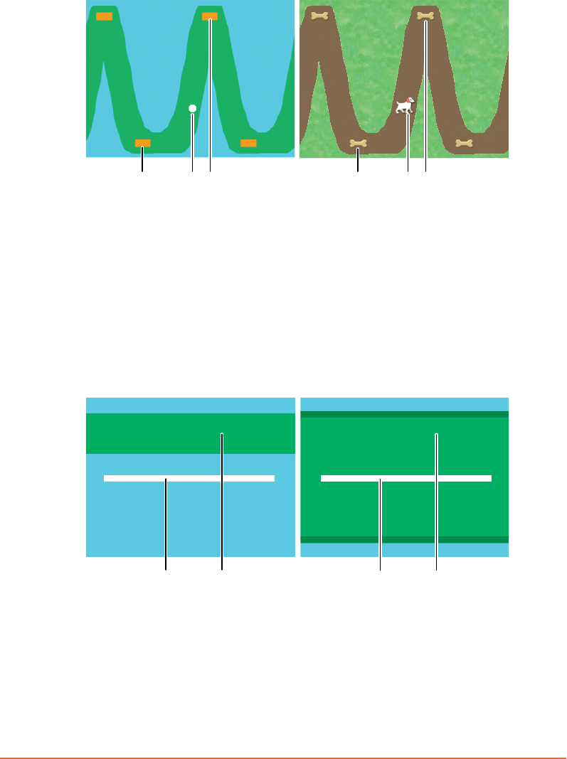
Curve and Dog visualize the targeted respiratory motion. These prompt styles are
intended for free-breathing gating. The waveform shape is determined during the
learning process and bases on the actual breathing paern of the patient.
1 12 23 3
1. Expiration peak target (optional)
2. Current breathing position
3. Inspiration peak target (optional)
Figure 9 Curve and Dog
Slider visualizes the target area in which the patient is expected to hold breath. Even
though this prompt style is primarily intended for breath-hold gating, it can also be
used for the free-breathing gating types. In the laer case, the target area represents
the gating window that the patient is expected to cover while breathing. Gating stops
as soon as the white slider touches the blue area.
1 2 1 2
1. Current breathing position
2. Gating window (target area)
Figure 10 Slider (breath-hold and free-breathing)
Chapter 5 Prepare the Session and the Patient
Draft (rco1321352456798 / Authoring:formal review / 11-Nov-2015 04:57 PST / asteinma)
43
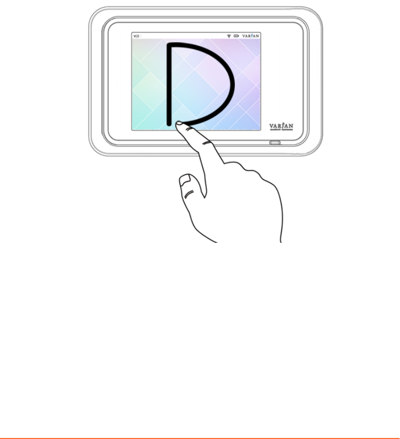
Using the VCD in Demo Mode
The VCD includes a demo mode to show the visual prompt styles to patients and
instruct them on how to breathe with assistance of the VCD.
■To enter the demo mode from the home screen, draw a capital D on the
touchscreen.
■To exit a prompt style animation, swipe from right to left on the touchscreen.
■To return to the home screen, touch the arrow symbol at the top left of the
touchscreen.
Figure 11 Enter Demo Mode of VCD
Related Topics
Using the VCD in Maintenance Mode on page 35
44
Draft (rco1321352456798 / Authoring:formal review / 11-Nov-2015 04:57 PST / asteinma)
Respiratory Gating for Scanners Instructions for Use
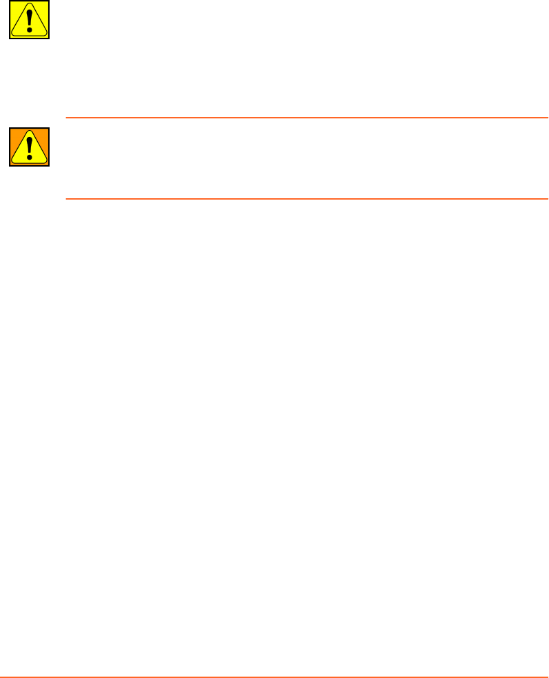
Place the Reflector Block
Before you place the reector block on the patient, always verify that it is clean and
undamaged.
CAUTION: Reuse of the reflector block can cause contamination to the patient. To avoid
contamination ensure that the reflector block is cleaned prior to each use according to
the cleaning instructions provided in this manual.
If a patient has open wounds, cuts, or other breaks in the skin, apply gauze or other
protective barrier between the reflector block and the skin surface to prevent risk of
infection or contamination.
WARNING: A wrong or damaged reflector block can cause an incorrect reflector block
position to be measured. Do not use any other reflector block other than the one
provided with the system (P/N B501928R02). Always visually inspect the reflector block
prior to each use. Replace the reflector block if any damage is noticed.
After seing up the patient, place the reector block as follows:
1. For the rst session, place the reector block with the reectors facing the
camera, where it is visible to the camera.
■For the actual placement take into account the consistency of chest wall
motion. Also, consult with the treatment planning team to establish the best
position. To obtain optimum performance, place the reector where vertical
movement is at least 4 mm.
■If no permanent or anatomical marks are used, mark the corners of the block
on the skin and use hospital tape or other appropriate means to replicate the
position as closely as possible from one session to the next. Advise the patient
not to let the marks wash or rub o.
2. For consecutive sessions, place and aach the reector block at the position
marked during previous sessions and refresh marks if necessary.
3. Ensure that the camera has unobstructed view of the reector block, and remove
objects or clothing if necessary.
Related Topics
Clean the Reector Block on page 28
Chapter 5 Prepare the Session and the Patient
Draft (rco1321352456798 / Authoring:formal review / 11-Nov-2015 04:57 PST / asteinma)
45

Learning the Breathing Pattern
Before the system is able to display and record respiratory motion data, it has to
adapt to the breathing paern of the patient. The learning process runs for a
minimum of four respiratory cycles. During the process, the system determines the
minimal and maximal vertical position of the reector block, the average inspiration
and expiration time, and the baseline. The generated data provides the scale of the
reector block motion for display purposes and for seing the thresholds. At this
point the periodicity lter checks that the respiratory trace (the reector block
position in relation to time) is regular. Once the stability of the minimal and maximal
positions is veried and breathing is regular, the system can be placed in record
mode.
Learning aects the motion range and coaching speed.
Motion Range If Automatically set motion range to learned range is enabled in
the coaching seings, the learned motion range is used for
coaching.
Coaching
Speed
If Automatically set coaching speed to learned speed is enabled
in the coaching seings, the learned breathing speed is used for
coaching.
For correct learning, the patient must exercise free breathing. If the system does not
complete the learning process, check the following:
■The reector block is visible to the camera for the entire respiratory cycle.
■Patient breathing is periodic (check the periodicity meter).
■The motion of the reector block is at least 4 mm in vertical direction.
■The breathing frequency is within 6-20 respiratory cycles per minute.
You can restart the learning process at any time for the following purposes:
■Adapt to signicant changes (range, speed and baseline) between the learning
process and the actual acquisition.
■Repeat an aempt that failed due to irregular breathing.
Note: If a couch-mounted camera is used on site and the camera gets disconnected while
tracking the reector block (during learning or else), reconnect the camera and restart
learning.
46
Draft (rco1321352456798 / Authoring:formal review / 11-Nov-2015 04:57 PST / asteinma)
Respiratory Gating for Scanners Instructions for Use

Baseline
The reference point from which respiratory motion and thresholds are measured is
the reector block position at the expiration peak, when the patient is relaxed and
breathing normally. Based on this position acquired during the learning process, the
system denes the baseline as 0.0 amplitude.
Adjusting the Gating Window
The system oers various ways of adjusting the thresholds of the gating window:
■In the Seings workspace, change the numeric value of the threshold.
■In the Scan workspace, you have the following options:
■Drag the threshold lines (blue and orange) one by one, or both together.
For amplitude and breath-hold gating, the threshold lines are located in the
respiratory trace chart. For phase gating, they are located in the phase dial.
To move the thresholds together (that is, the entire gating window), click
somewhere between the threshold lines and drag the gating window.
To move one threshold alone, click and drag the threshold line.
■Change the numeric value of the threshold, then press TAB to apply the
change.
Scaling
The respiratory trace chart visualizes two axes: time and motion. The default scale in
the time axis is 5 seconds. The scale of the motion axis depends on the learned
respiratory trace. Auto Scale is selected by default, but you can adjust the scale and
view. As a consequence of some types of adjustments, auto-scaling is disabled.
■To change the scale of the time axis, press Shift and scroll.
■To change the scale of the motion axis, press Ctrl and scroll.
■To move the respiratory trace up and down (including baseline and thresholds)
without changing the scale, press Shift and drag.
■To choose dierent views (Left-Right and Head-Feet) of the respiratory trace
without changing the scale, right-click.
Chapter 5 Prepare the Session and the Patient
Draft (rco1321352456798 / Authoring:formal review / 11-Nov-2015 04:57 PST / asteinma)
47
Chapter 6 Acquire Respiration-Synchronized
Images
Prepare the Scanner
The following instructions assume that you have prepared a session and set up the
patient.
1. Open the patient record on the scanner.
2. Prepare the scan (that is, select a scan protocol, adjust scan parameters).
3. Verify that the patient sees the VCD, and that the VCD does not collide with the
scanner gantry.
CAUTION: A collision of the Visual Coaching Device with the scanner can cause damage
to the scanner, VCD and other accessories. To avoid a collision with the scanner always
verify that the clearance inside the scanner gantry is sufficient for the defined
configuration of the Visual Coaching Device mount with regard to couch movements
during the scanning process.
4. Acquire a scout image (topogram).
5. Determine the scan range and reconstruction volume for nal image acquisition.
Proceed to acquire respiration-synchronized images with prospective or
retrospective gating.
Acquire Images with Prospective Gating
The following instructions assume that you have prepared the scanner and a session,
and set up the patient for one of the following types of gating:
■Phase gating
■Amplitude gating
■Breath-hold gating
1. Start audio or video coaching or both and instruct the patient to breathe
accordingly.
2. Start recording the respiratory trace.
3. Start the gating signal.
4. When the respiratory trace is regular, start the scanner.
5. Monitor the respiratory trace for irregularities.
6. When image acquisition is complete, stop recording the respiratory trace.
48
Draft (rco1321352456798 / Authoring:formal review / 11-Nov-2015 04:57 PST / asteinma)
Respiratory Gating for Scanners Instructions for Use
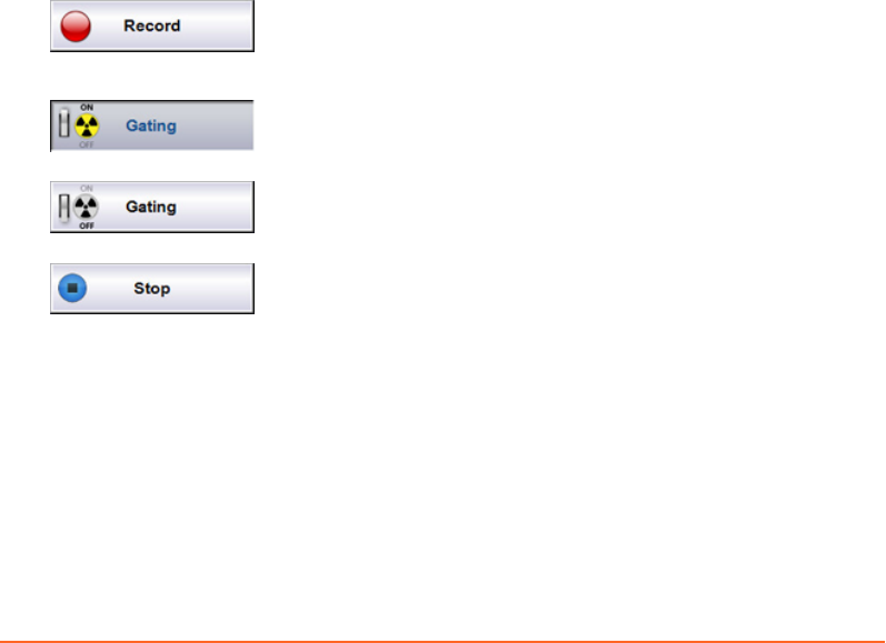
7. Instruct the patient to breathe regularly again.
Proceed to review and nalize the session.
Acquire Images with Retrospective Gating
The following instructions assume that you have prepared the scanner and a session,
and set up the patient for 4D scan gating.
1. Start audio or video coaching or both.
2. Start recording the respiratory trace.
3. Start the gating signal.
For some scanners, you do not need to start gating for 4D scans.
4. When the respiratory trace is regular, start the scanner.
5. Monitor the respiratory trace for irregularities.
6. When image acquisition is complete, stop recording the respiratory trace.
7. Instruct the patient to breathe regularly again.
Proceed to review and nalize the session.
Gating Buttons
Starts recording of respiratory motion. Recording does not
include sending trigger signals to the scanner. During
recording, it is not possible to change the thresholds.
Starts and stops the sending of trigger signals to the scanner.
ON means that trigger signals are sent to the scanner.
Starts and stops the sending of trigger signals to the scanner.
OFF means that no trigger signals are sent to the scanner.
Stops recording of respiratory motion and disables the gating
output.
Monitoring the Respiratory Trace
The system provides various features for monitoring the quality of the respiratory
trace and the gating process.
Stop gating if the periodicity is continuously poor, or if the baseline drifts
signicantly (according to clinical policy).
Chapter 6 Acquire Respiration-Synchronized Images
Draft (rco1321352456798 / Authoring:formal review / 11-Nov-2015 04:57 PST / asteinma)
49
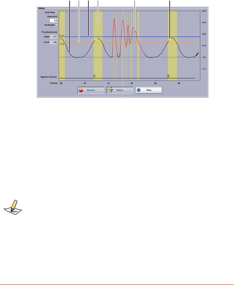
Colors Used in The Respiratory Trace Chart
Once you start recording, the respiratory trace and gating data is visualized in
dierent colors.
32 64 51
1. Black trace: regular periodic breathing
2. Orange line: lower threshold
3. Blue line: upper threshold
4. Yellow column: breathing within gating window
5. Red trace: Irregular non-periodic breathing or reflector block not tracked correctly
6. Yellow trace: X-Ray On signal from scanner
Figure 12 Respiratory Trace Chart Colors
For comparison, you can select the Verication option, which adds a green
verication trace behind the current trace. The verication trace is only available if a
recording has been made or opened for the same session beforehand (for example, in
a training session).
Note: If the scanner does not provide X-Ray On information, the respiratory trace does not
turn yellow during image acquisition.
Phase Dial
The phase dial shows the gating thresholds along a clockwise motion of the
respiratory cycle. If breathing is irregular (poor periodicity), the needle jumps
around.
50
Draft (rco1321352456798 / Authoring:formal review / 11-Nov-2015 04:57 PST / asteinma)
Respiratory Gating for Scanners Instructions for Use
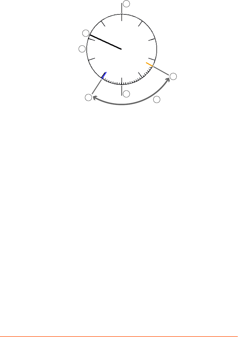
60%
33%
100%
3
50%
0%
2
54
7
1
6
1. Phase dial with indicators after each 10% (1% indicators appear in the gating window)
2. Needle indicating the current phase position in percent
3. Inspiration peak (approximate)
4. Expiration peak (approximate)
5. Upper gating threshold (blue)
6. Lower gating threshold (orange)
7. Gating window
Figure 13 Phase Dial
Periodicity Meter
The system is capable of tracking respiratory rates ranging of 6-20 respiratory cycles
per minute. An algorithm is used to calculate the similarity or dierence of
respiratory motion data over time. Assuming that the patient generally has a regular
and steady breathing paern, the goal of the calculation is to monitor any variance
between the current and previous respiratory cycles.
The calculated value is referred to as the periodicity. The system recalculates the
periodicity in real time.
The periodicity meter visualizes the regularity of breathing as a bar stretching along
a horizontal line. This visual aid enables an estimate for the regularity and quality of
the breathing paern. A threshold (marked by a vertical line) is specied with the
breathing predictive lter. As long as the periodicity is good, the bar is displayed in
black.
Chapter 6 Acquire Respiration-Synchronized Images
Draft (rco1321352456798 / Authoring:formal review / 11-Nov-2015 04:57 PST / asteinma)
51

As soon as the periodicity becomes poor, the bar stretches to the right, it turns red,
and the system stops the trigger signals. The same applies when the system is unable
to track the reector block.
13
24
1. Current quality (turns red if poor)
2. Good quality
3. Threshold of breathing predictive filter (always in the middle of the range).
4. Poor quality
Figure 14 Periodicity Meter
Related Topics
Using the Breathing Predictive Filter on page 41
Monitoring of Patient Motion
Monitoring of patient motion tracks in real time the position of the reector block in
vertical, lateral, and longitudinal dimensions. If visual monitoring is enabled and the
reector block moves out of the motion range identied during the learning process,
the color of the ball (representing the reector block) and of the aected axis changes.
If visual monitoring is disabled, the position of the reector block is tracked but
deviations are not visualized.
Figure 15 Monitoring of Patient Motion
The following visual aids are in use:
52
Draft (rco1321352456798 / Authoring:formal review / 11-Nov-2015 04:57 PST / asteinma)
Respiratory Gating for Scanners Instructions for Use

Ball The ball represents the current position of the reector block in relation to
the body axes.
Green Patient motion is within the motion range identied during the learning
process.
Yellow Patient motion is out of the motion range identied during the learning
process by 1% to 15%.
Red Patient motion is out of the motion range identied during the learning
process by more than 15%.
In addition to the visual aids, the following reference information is available.
Capital
Leers
The capital leers designate the orientation of the body axes: A
(anterior), P (posterior), R (right), L (left), H (head), F (feet).
Numeric
Values
The value at the top of the anterior-posterior axis indicates the current
position of the reector block in relation to the baseline.
The value on the right of the left-right axis indicates the current
position of the reector block in relation to the average left-right
position identied during the learning process.
The value at the boom left indicates the current position of the
reector block in relation to the average head-feat position identied
during the learning process. Head-to-feet motion is not visualized but
only indicated as numeric values.
Related Topics
Enabling Visual Monitoring of Patient Motion on page 41
About Phase Calculation in Real Time
Phase calculation is used both for phase gating and for determining the periodicity.
The calculation converts the respiratory trace from a displacement signal as a
function of time into values representing where the current sample falls along a sinus
curve as a function of time. The phase is therefore an indicator of where the current
time point falls within the interval of two consecutive end-inhale time points.
To obtain the phase, a peak-trough detection algorithm estimates the end-inhale and
end-exhale time points and generates an estimate of the breathing period (time of a
respiratory cycle) that is updated with every newly detected end-inhale and end-
exhale time point. The breathing period is then used to select the points in the
respiratory trace that are required for phase calculation.
Chapter 6 Acquire Respiration-Synchronized Images
Draft (rco1321352456798 / Authoring:formal review / 11-Nov-2015 04:57 PST / asteinma)
53

The phase of each new sample of the respiratory trace is dened as the phase angle of
the rst harmonic complex Fourier coecient calculated over a sliding time window,
which is dened by the breathing period. The resulting value is shifted by π because
the end-inhale is at signal minimum. In a sinus curve, phase calculation results in a
value of 0% for the inspiration peak, 50% (π) for the expiration peak, and 100% (2 π)
for the consecutive inspiration peak.
Challenges
The challenge in phase calculation is that the breathing period used to estimate the
phase is a lagging value, representing the duration of the previous breathing period.
The duration of the current breathing period is unknown until detection of the next
end-inhale time point. As long as the breathing period does not change substantially
from one respiratory cycle to the next (for example, by ≤10%), the phase is a linear
(saw tooth) plot as a function of time. If the breathing period changes signicantly
(for example, by ≥ 10%) from one respiratory cycle to the next, the phase is not a
linear function of time and the phase values of 0% and 100% do not represent the
exact end-inhale time points.
If the breathing paern of a patient is asymmetric (varying duration of inspiration
versus expiration) or irregular (varying duration of breathing periods, or varying
amplitude values), the system does not establish xed phase values for inspiration
and expiration peaks.
Audio and visual coaching can support the patient to breathe regularly with a
constant breathing period. This will ensure a stable phase calculation. When using
phase values for retrospective 4D reconstruction, use phase recalculation when
reviewing the session.
Related Topics
Reviewing a Session on page 55
54
Draft (rco1321352456798 / Authoring:formal review / 11-Nov-2015 04:57 PST / asteinma)
Respiratory Gating for Scanners Instructions for Use

Chapter 7 Finalize the Session
Finalize the Session (Overview)
The following instructions assume that you have just acquired respiration-
synchronized images.
1. Review the recorded respiratory trace with special aention to the following:
■Breathing phase (for 4D reconstruction)
■Thresholds
■Baseline drift
2. If necessary, change the gating type for treatment delivery.
3. If necessary, export the session (breathing data) to the le system, and import it
from there to the scanner or the treatment delivery system.
In database mode with ARIA® OIS for Radiation Oncology 13.0 or higher, manual
data export is not required.
4. Close the session.
5. Help up the patient.
6. If necessary, dismount the VCD and the camera from the couch.
Reviewing a Session
Retrospective Gating
For retrospective gating, you can recalculate the breathing phase, adjust thresholds,
and add or delete peaks of the respiratory trace. Breathing phase values are indicated
as a gray line that typically has a saw tooth shape.
Use Auto Detect to have the system recalculate the breathing phase of the recorded
trace. Contrary to phase calculations during image acquisition, this considers the
entire trace information and generally leads to higher image quality in 4D
reconstructions. For phase recalculation, the system auto-detects the inspiration
peaks of the respiratory trace and interpolates the phase linearly over time from 0%
to 100% between two consecutive peaks. As a result you get consistent phase values
even if breathing periods dier signicantly from one respiratory cycle to the next. If
automatic phase recalculation is enabled, the eect is the same as selecting Auto
Detect.
Chapter 7 Finalize the Session
Draft (rco1321352456798 / Authoring:formal review / 11-Nov-2015 04:57 PST / asteinma)
55

Use the + and – buons to add or remove inspiration peaks manually. Click the
respective buon again to disable the editing of the breathing phase. This switches
back to editing of the gating thresholds if gating thresholds are dened.
Note: Various factors can lead to data being unusable for 4D reconstruction on the scanner
system. Always review the recorded respiratory trace. If necessary, correct the inspiration
peaks and execute a phase recalculation.
Prospective Gating
For prospective gating, you can review and adjust thresholds.
Note: This task requires special user rights and user authentication.
If you adjust the thresholds, the yellow columns in the chart as well as the values for
duty cycle and gated motion change accordingly. Adjustments to the thresholds are
stored in the current session.
■To adjust amplitude thresholds, drag the respective line in the Recording chart to
the wanted location or enter the corresponding values.
■To adjust phase thresholds, drag the respective line in the Phase dial to the
wanted location or enter the corresponding values.
All Types of Gating
Recording Use the playback buons and the position slider, to move along
the recorded trace and view the parameters.
Measured
Values
Review the values set for the recorded session.
Baseline The baseline shift is calculated based on the average of all
expiration peaks of the recorded respiratory trace compared with
the learned baseline. If you apply a baseline shift, the trace shifts
accordingly and amplitude thresholds are adapted.
Shifting the Baseline
During recording, the expiration peaks can move away from the 0.0 reference
position. This change is referred to as baseline drift.
A baseline drift occurs when the average of the expiration peaks calculated during
the learning phase diers from the expiration peaks after starting the recording.
56
Draft (rco1321352456798 / Authoring:formal review / 11-Nov-2015 04:57 PST / asteinma)
Respiratory Gating for Scanners Instructions for Use
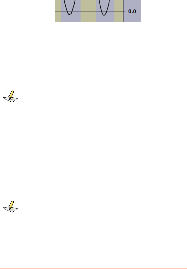
Figure 16 Baseline Drift
Applying a Baseline Shift
In connection with treatment delivery, a baseline drift leads to incorrect thresholds
for amplitude and breath-hold gating. Therefore, apply a baseline shift when it is
apparent that the baseline has drifted. You can edit the calculated shift value if
necessary.
Applying a shift means shifting the coordinate system. It leads to the recalculation of
the respiratory trace and thresholds.
Note: This task requires special user rights and user authentication.
Gating Type for Treatment
Except for images acquired with breath-hold gating, you can change type of gating
for future treatment sessions. That is, you can acquire an image with a certain gating
type, change it, adjust thresholds and store the new seings for treatment delivery.
The goal is typically to have comparable conditions for image acquisition and
treatment delivery. Only change the gating type for treatment if compelling reasons
exist (for example, if site policy mandates one gating type for image acquisition and
the other for treatment delivery).
■To adjust amplitude thresholds, drag the respective line in the Recording chart to
the wanted location or enter the corresponding values.
■To adjust phase thresholds, drag the respective line in the Phase dial to the
wanted location or enter the corresponding values.
Note: This task requires special user rights and user authentication.
Export for Treatment
Depending on the system conguration, one or both of the following features are
available to export data for gated treatment delivery:
Chapter 7 Finalize the Session
Draft (rco1321352456798 / Authoring:formal review / 11-Nov-2015 04:57 PST / asteinma)
57

Export to RPM
Use this feature for Clinac™ systems that support gating with an Real-time Position
Management™ system (RPM). It exports gating data and patient data to the RPM
database, and includes all seings (gating seings, coaching seings) of the gating
session and the recorded trace.
Export to DICOM
Use this feature to export data to TrueBeam™, VitalBeam™, or Edge™ systems with the
following OIS:
■Third-party OIS
■ARIA® OIS for Radiation Oncology 11.0 or lower
■If in le mode, ARIA® OIS for Radiation Oncology 13.0 or higher
Note: If in database mode, manual export is not required with ARIA® OIS for Radiation
Oncology 13.0 or higher.
Export for 4D Reconstruction
Use the Export to VXP feature to export data from a recording session to a
predetermined location and to use the data for 4D reconstruction on a scanner
workstation.
To create an export le according to local le name convention, enter the requested
information (depends on scanner).
Depending on the scanner on site, manual VXP export may not be required thanks to
real-time data exchange via serial interface.
Select a Start Time for VXP Export
When exporting data for 4D reconstruction, you can select a starting point from
which to start the export. This can be useful when scout scan data is part of the
recorded trace and you want to exclude that data from the export.
1. Under Export for 4D Reconstruction select Start Time.
2. Move the position slider in the recording control bar to the relevant time range.
For scanners that provide X-Ray On signal on the RGSC interface, the scout scan
and actual scan can be identied on the trace where it appears yellow (X-Ray
On).
3. Move the cursor into the recording chart, to the beginning of the time range you
want to export.
A green vertical line appears and follows the cursor.
58
Draft (rco1321352456798 / Authoring:formal review / 11-Nov-2015 04:57 PST / asteinma)
Respiratory Gating for Scanners Instructions for Use

4. To set the start time, click into the recording chart.
Close the Session
How you can close a session depends on the workspace. Closing the session saves all
related data.
■In the Review workspace, click OK in the control bar or Close in the workow
panel.
■In any other workspace, click Close in the workow panel.
Shut Down the System
Shut down the system at the end of each working day.
1. On the application home screen, click Exit Application.
2. Shut down Windows.
NOTICE: Do not turn off the Real Time Unit or main power switch. Switching off the Real
Time Unit can result in damage to the scanner interface and to the flash card.
Chapter 7 Finalize the Session
Draft (rco1321352456798 / Authoring:formal review / 11-Nov-2015 04:57 PST / asteinma)
59
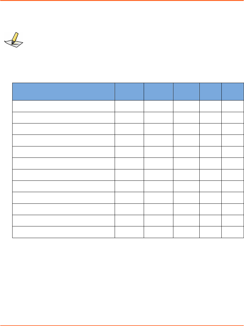
Appendix A System Configuration
User Groups
Note: User administration is integrated into the Varian Oncology Systems Platform (OSP
server or client) and independent from Windows.
The following user groups are available:
Table 2 User Groups and Rights
User Group Rights Therapist Oncolo-
gist
Physicist Admin Service
Perform a clinical workow. ✓ ✓ ✓ ✓ ✓
Verify camera calibration. ✓ ✓ ✓ ✓ ✓
Change the gating mode for treatment. - ✓ ✓ - -
Change thresholds in review. - ✓ ✓ - -
Save scan seings as template. - - ✓ ✓ ✓
Calibrate the camera. - - ✓ ✓ ✓
Congure the system. - - ✓ ✓ ✓
Install the camera. - - - - ✓
Congure the camera. - - - - ✓
Congure the scanner. - - - - ✓
Upload software for VCD. - - - - ✓
Upload software for Real-Time Unit. - - - - ✓
Application
To access the workspace, choose Conguration > Application.
60
Draft (rco1321352456798 / Authoring:formal review / 11-Nov-2015 04:57 PST / asteinma)
Respiratory Gating for Scanners Instructions for Use

Coaching
Control Description
Audio Coaching Oset
[s]
Specify the oset according to the desired time lapse.
Audio coaching starts with this oset before the inspiration or ex-
piration peak is predicted.
Verification
This seing is only enabled in connection with a wall-mounted or ceiling-mounted
camera.
Control Description
Verication Period [days] Specify the number of days during which the camera verication
is valid. If the verication is outdated, a new verication will be
enforced.
Calibration
This seing is only enabled in connection with a couch-mounted camera.
Control Description
Calibration Period [days] Specify the number of days during which the camera calibration
is valid. If the calibration is outdated, a new calibration will be en-
forced.
DICOM Import/Export
Control Description
Specic Character Set Select the applicable character set.
The applicable character set depends on the DB daemon or, if ap-
plicable, on the TrueBeam system.
Export
To access the workspace, choose Conguration > Export.
Appendix A System Configuration
Draft (rco1321352456798 / Authoring:formal review / 11-Nov-2015 04:57 PST / asteinma)
61

VXP Export
Control Description
Enable VXP le export Select to enable the VXP export option in the Review workspace.
Directory Specify the le path of the target database for export.
File Name Format Specify the le name format according to the format that is ex-
pected by the 4D reconstruction software of the scanner.
Automatic phase recalcu-
lation
Select to enable automatic o‐line phase processing when en-
tering the Review workspace.
Prompt for VXP export
in retrospectively gated
cases
Select to activate an export prompt when you close the session
after review.
RPM Export
Control Description
Enable RPM data export Select to enable the RPM export option in the Review workspace.
RPM Database File Specify the le name and path of the target database for export.
Automatic export after
acquisition
Select to enable automatic export when you close the session after
review.
Prompt for manual ex-
port after acquisition
Select to activate an export prompt when you close the session
after review.
RPM System Frame Rate Select the required frame rate.
DICOM Export
Control Description
Enable DICOM le ex-
port
Select to enable the DICOM export option in the Review work-
space.
Directory Specify the le path of the target database for export.
Patient‐specic Folder
Format
Specify the folder name format for patient data.
Automatic export after
acquisition
Select to enable automatic export when you close the session after
review.
Prompt for manual ex-
port after acquisition
Select to activate an export prompt when you close the session
after review.
62
Draft (rco1321352456798 / Authoring:formal review / 11-Nov-2015 04:57 PST / asteinma)
Respiratory Gating for Scanners Instructions for Use
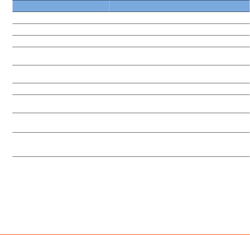
Export File Structure and Format
The system supports the export of motion data les for post-processing. Motion data
les are created in text format after data acquisition is nished or when a previously
recorded session is retrieved.
A text le is used for the export parameters. Depending on the scanner, the le name
must follow one of the following formats for 4D reconstruction.
■PatientID_ExamNumber_SeriesNumber.vxp
■PatientID_SessionNumber.vxp
Data contained in the export le is organized into a header section and a data section.
The <cr> symbol represents a carriage return.
Header Section
Line Data Format Description
1 [Header]<cr> Prex of the header section
2 CRC=crcChecksum<cr> CRC checksum
3 Version=versionNumber<cr> The version number of the export le
4Data_layout=eld1[,eld2...],
eldn<cr>
The layout of the data section; eld1 through eldn
represent the names of the elds in the data section.
5 Patient_ID=patId<cr> The Patient ID of the patient record created in RGSC
system
6 Date=mm-dd-yyyy<cr> The date the acquisition session was recorded
7 Total_study_time=studyTime
<cr>
The actual recording length in seconds to a thou-
sandth of a second
8 Samples_per_second=sampl-
eRate <cr>
■NTSC: 30 or 15
■CCIR: 25 or 12.5
9 Scale_factor=scale<cr> The scale factor for the signal data (in mm). For ex-
ample, if the data eld ValueOfRespiratoryWave is
given in cm, the scale factor is 10.0.
Data Section
At line 10, [Data]<cr> is used to demarcate the beginning of the data section, whose
data elds are separated by comma.
The layout of the data section, is dened in line 4 of the header section. This version’s
format is described in the following table.
Appendix A System Configuration
Draft (rco1321352456798 / Authoring:formal review / 11-Nov-2015 04:57 PST / asteinma)
63

Field Description
Value_of_respiratory_wave Position in centimeters relative to reference
Phase_value Phase value for the current sample
Time_Stamp Time of the sample measurement in milliseconds
Valid_Flag ■≥ 0: a valid track and a periodic signal
■< 0: either a lost track, a bad video signal, or a non-
periodic signal
TTL_In Bit value indicating the status of a sensed x-ray on signal
from scanner
■1: +5 VDC
■0: 0 VDC
Mark Leer specifying the sample when the phase value is
closest to 0 or pi
■Z: 0 phase
■P: pi phase null string: no data
TTL_Out Bit value indicating the status of a gating signal to the
scanner
■1: +5 VDC
■0: 0 VDC
Example
The following is a fragment of a sample export le:
[Header]
CRC=53224
Version=1.6
Data_layout=amplitude,phase,timestamp,validflag,ttlin,mark,ttlo
ut
Patient_ID=990310B
Date=10-06-2012
Total_study_time=32.533
Samples_per_second=30
Scale_factor=10.0
[Data]
4.7171,1.4994,29441,0,1,,0
64
Draft (rco1321352456798 / Authoring:formal review / 11-Nov-2015 04:57 PST / asteinma)
Respiratory Gating for Scanners Instructions for Use
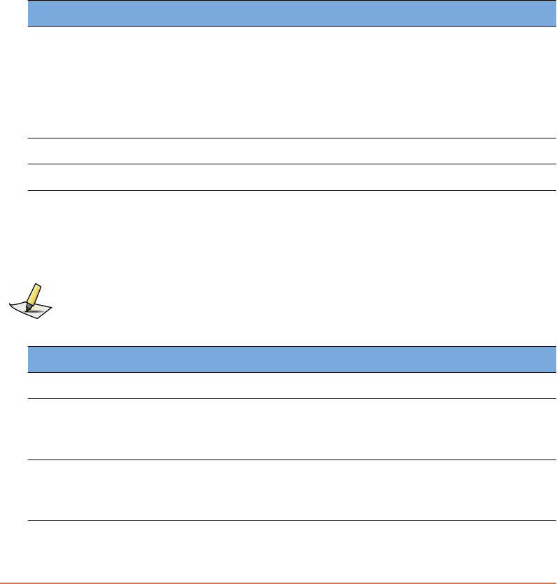
4.7189,1.5135,29464,0,1,,0
...
5.0888,2.3434,30384,0,1,,0
5.0998,2.3695,30401,0,1,,0
Scanner
To access the workspace, choose Conguration > Scanner.
Select Scanner
Control Description
Manufacturer Select the manufacturer of the scanner:
■User dened (all seings customizable)
■Siemens
■Toshiba
■Philips
■GE Healthcare
Product Name Select the scanner/interface.
Description Comment in the context of the seing.
Scanner Interface
These seings dene how data is transferred through the binary lines and through
the serial interface.
Note: For a compatible scanner connection, the following seings need to be congured
properly. These seings can only be changed when User dened is selected as manufacturer.
Control Description
Trigger Signal Length [s] Specify the length of the trigger signal. Default is 0.50.
Trigger Signal Polarity Select the polarity of the binary output line.
■Positive Pulse (default)
■Negative Pulse
X-Ray On Signal Polarity Select the polarity of the binary input line.
■High signal means ON (default)
■Low signal means ON
Appendix A System Configuration
Draft (rco1321352456798 / Authoring:formal review / 11-Nov-2015 04:57 PST / asteinma)
65

Control Description
X-Ray On Signal Circuit ■Single-Ended (default)
■Dierential
Heartbeat Signal Specify whether a heartbeat signal between scanner and RGSC ex-
ists.
■Not supported (default)
■Supported
Heartbeat Timeout [s] Specify the length of the heartbeat timeout. Default is 0.5.
Serial Data Interface
Control Description
Baud Rate ■34800 (default)
■1152000
Stop Bits ■1 (default)
■2
Parity ■None (default)
■Even
■Odd
Flow Control ■None (default)
■RTS/CTS
Output for 4D Scanning
Control Description
Trigger at [°] Specify the phase at triggers are to be sent for retrospective gating
(4D reconstruction). Default is 0.
Output for Breath Hold Scanning
Control Description
Breath Hold Signal ■Continuous (default)
■Single Trigger
■Burst Triggers
Burst Trigger allows acquiring multiple slices per breath-hold
cycle.
66
Draft (rco1321352456798 / Authoring:formal review / 11-Nov-2015 04:57 PST / asteinma)
Respiratory Gating for Scanners Instructions for Use
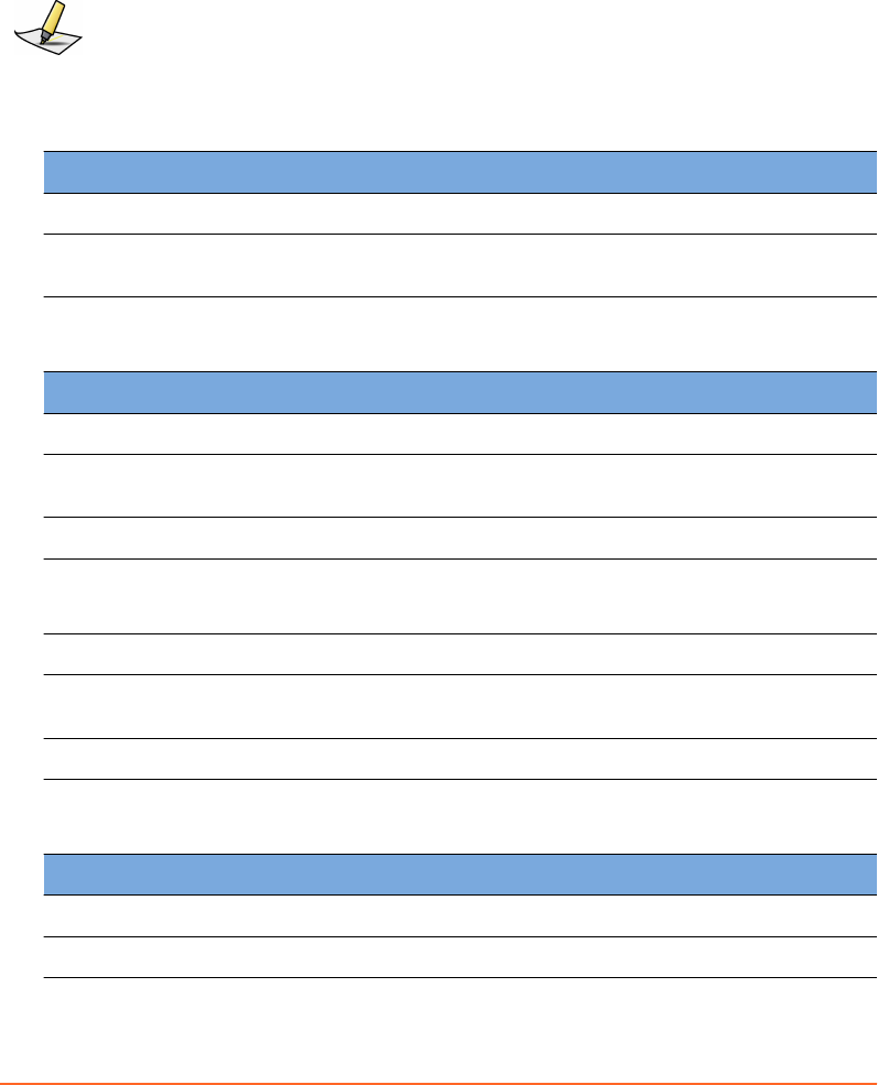
VCD
To access the workspace, choose Conguration > VCD. The workspace is only
available, if visual coaching is in use.
Note: The VCD must be connected and turned on.
Software Version
Control Description
Application Version Current application version installed on the VCD
Operating System Ver-
sion
Current operating system version installed on the VCD
Battery Status
Control Description
Charge Status [%] Status of the baery
Remaining Capacity
[mAh]
Remaining capacity of the baery
Voltage [V] Current cell voltage
Low Baery Warning
Level [%]
Specify when to issue an alert that the baery charge status is low.
If the charge status is lower, do not start a new recording.
Power Supply External or baery powered
Number of Charging Cy-
cles
Accumulated number of charge and discharge cycles
Temperature [°C] Temperature of the baery
Software Update
Control Description
Application Download le
Operating System Download le
Appendix A System Configuration
Draft (rco1321352456798 / Authoring:formal review / 11-Nov-2015 04:57 PST / asteinma)
67

Database
To access the workspace, choose Conguration > Database.
DICOM Stream Service Connection
Control Description
DSS Host Specify the host name of the DSS (DICOM Stream Service) work-
station
DSS Port Specify the port number to connect to the DSS.
Daemon Connection
Control Description
Enable Database Mode
(with ARIA DB)
Enable the system to run in database mode. Only a Varian System
database is supported.
Enable Patient Creation
(Activate UI)
Enable the system to support local patient creation. If disabled,
the patient must exist in the database.
Local Host Specify the host name of the DSS workstation.
Local Port Specify the port number of the connection from DB Daemon to
DSS.
Local AE Title Specify the entity name of the DSS application.
Remote Host Specify the host name of the DB Daemon workstation.
Remote Port Specify the port number of the connection from DSS to DB
daemon.
Remote AE Title Specify the entity name of the DB Daemon.
File Mode
Control Description
Enable File Mode Enable the system to run in le mode. Data is stored as DICOM
les.
Patient Data Path Specify the location where the system creates a subfolder per pa-
tient and stores all sessions and DICOM les.
Patient Archive Path Specify the location where the system archives patient data.
68
Draft (rco1321352456798 / Authoring:formal review / 11-Nov-2015 04:57 PST / asteinma)
Respiratory Gating for Scanners Instructions for Use
Services
Control Description
DICOM Stream Service Status of the DSS
DB Daemon Service Status of the DB Daemon Service (may not be applicable in le
mode)
Archive
To access the workspace, choose Conguration > Archive.
■To nd a specic patient, enter search criteria in the available text boxes.
■To select consecutive les, click the rst le, press and hold down Shift, and then
click the last item.
■To select non-consecutive les, press and hold Ctrl, then click each le you want
to select.
Patient Data Content
Control Description
Move Selection to Ar-
chive
Archive selected patient les.
Patient Archive
Control Description
Restore Selection from
Archive
Restore selected patient les.
Note: If you change from database mode to le mode or vice versa, the Archive only becomes
available after exiting and re-entering the application.
Camera
To access the workspace, choose Conguration > Camera.
Appendix A System Configuration
Draft (rco1321352456798 / Authoring:formal review / 11-Nov-2015 04:57 PST / asteinma)
69

Camera
Control Description
Conguration Changing the camera seings is reserved to Varian Service per-
sonnel.
Available congurations are the following:
■Wall Mount (25 mm)
■Ceiling Mount (Upside down, 25 mm)
■Couch Mount (12 mm)
Camera Installation Changing the camera seings is reserved to Varian Service per-
sonnel.
70
Draft (rco1321352456798 / Authoring:formal review / 11-Nov-2015 04:57 PST / asteinma)
Respiratory Gating for Scanners Instructions for Use

Appendix B EMC Data and Guidance
Electromagnetic Compatibility (EMC)
Respiratory Gating for Scanners (RGSC) is EMC-tested in conformity with the
requirements of IEC 60601-1-2:2007 and can be used in the vicinity of other EMC-
tested devices that fulll the requirements of the relevant IEC 60601-1-2 standard.
Untested HF (high-frequency) sources, radio networks or the like can inuence the
operation of the device and may not be operated in combination with the system.
Use of accessories, transducers and cables other than those specied (or supplied
with the system as replacement parts for internal components) may result in
increased emissions or decreased immunity of the system.
The following table is pursuant to IEC 60601-1-2. The cables listed meet IEC60601-1-2
emissions requirements.
Table 3 Cables and Maximum Lengths
Part Number Name Maximum Length
B501272 Cable CTIF – Single Camera (W01) 35 m
B504863 Cable Ethernet Single Camera (W02) 35 m
B504867 Cable Ethernet AP6511 (W03) 35 m
B503295 Cable GND Cabinet – Cam Mount (W04) 35 m
B504864 Cable GND Camera – Cam Mount (W05) 15 cm
P1012814 Camera Cable (W06) 10 m
Electromagnetic Interference (EMI)
To prevent damage or injury to electronic equipment resulting from EMI
interference, follow these instructions:
■Avoid use of unnecessary electrical devices near the scanner and the system.
■Use only Varian accessories, transducers, and cables.
■Do not use or stack the equipment with other equipment than compatible
scanners. If adjacent or stacked use is necessary, place the equipment in the
conguration in which it will be used prior to clinical use and observe its behavior
to verify normal operation.
■Allow only trained, qualied personnel to operate or maintain the system.
Appendix B EMC Data and Guidance
Draft (rco1321352456798 / Authoring:formal review / 11-Nov-2015 04:57 PST / asteinma)
71
Varian Test Declarations and Guidance
Note: This equipment has been tested and found to comply with the limits for a Class B digital
device, pursuant to Part 15 of the FCC Rules and meets all requirements of the Canadian
Interference-Causing Equipment Standard ICES-003 for digital apparatus. These limits are
designed to provide reasonable protection against harmful interference in a residential
installation. This equipment generates, uses, and can radiate radio frequency energy and, if
not installed and used in accordance with the instructions, may cause harmful interference to
radio communications. However, there is no guarantee that interference will not occur in a
particular installation. If this equipment does cause harmful interference to radio or television
reception, which can be determined by turning the equipment o and on, the user is
encouraged to try to correct the interference by one or more of the following measures:
■
Reorient or relocate the receiving antenna.
■
Increase the separation between the equipment and receiver.
■
Connect the equipment into an outlet on a circuit dierent from that to which the receiver
is connected.
■
Contact Varian Support services for help.
Note: You must verify the actual shielding eectiveness and lter aenuation of the shielded
location to ensure that they meet the minimum specications.
Electromagnetic Immunity
The system is intended for use in the electromagnetic environment specied below.
The customer or the user of the system should assure that system is used in such
environment.
72
Draft (rco1321352456798 / Authoring:formal review / 11-Nov-2015 04:57 PST / asteinma)
Respiratory Gating for Scanners Instructions for Use

Table 4 Electromagnetic Compatibility (EMC, IEC 60601-1-2:2007, Table 1)
Emissions Test Compli-
ance
Electromagnetic Environment Guidance
RF emissions
CISPR 11
Group 1 The system uses RF energy only for its internal function.
Therefore, its RF emissions are very low and are not likely to
cause any interference with nearby electronic equipment.
RF emissions
CISPR 11
Class B The system is suitable for use in all establishments, in-
cluding domestic establishments and those directly con-
nected to the public low-voltage power supply network that
supplies buildings used for domestic purposes.
Harmonic emis-
sions
IEC 61000-3-2
Class A
Voltage uctu‐
tions / icker
emissions
IEC 61000-3-3
Complies
Table 5 Electromagnetic Compatibility (EMC, IEC 60601-1-2:2007, Table 2)
Immunity Test IEC 60601 Test Level Compliance Level Electromagnetic Envi-
ronment Guidance
Electrostatic dis-
charge (ESD)
IEC 61000-4-2
±6 kV contact
±8 kV air
±6 kV contact
±8 kV air
Floors should be
wood, concrete or ce-
ramic tile. If oors are
covered with syn-
thetic material, the
relative humidity
should be at least
30 %.
Electrical fast tran-
sient/burst
IEC 61000-4-4
±2 kV for power
supply lines
±1 kV for input/
output lines
±2 kV for power
supply lines
±1 kV for input/
output lines
Mains power quality
should be that of a
typical commercial or
hospital environment.
Surge
IEC 61000-4-5
±1 kV dierential
mode
±2 kV line(s) to earth
±1 kV dierential
mode
±2 kV line(s) to earth
Appendix B EMC Data and Guidance
Draft (rco1321352456798 / Authoring:formal review / 11-Nov-2015 04:57 PST / asteinma)
73
Immunity Test IEC 60601 Test Level Compliance Level Electromagnetic Envi-
ronment Guidance
Voltage dips, short in-
terruptions and
voltage variations on
power supply input
lines
IEC 61000-4-11
<5% UT (>95% dip in
UT) for 0.5 cycle
40% UT (60% dip in
UT) for 5 cycles
70% UT (30% dip in
UT) for 25 cycles
<5% UT (>95% dip in
UT) for 5 seconds
<5% UT (>95% dip in
UT) for 0.5 cycle
40% UT (60% dip in
UT) for 5 cycles
70% UT (30% dip in
UT) for 25 cycles
<5% UT (>95% dip in
UT) for 5 seconds
Mains power quality
should be that of a
typical commercial or
hospital environment.
If the user of the
system requires con-
tinued operation
during power mains
interruptions, it is rec-
ommended that the
system be powered
from an uninterrup-
tible power supply or
a baery.
Power frequency
(50/60 Hz) magnetic
eld
IEC 61000-4-8
100 A/m 30 A/m Power frequency
magnetic elds
should be at levels of
a typical commercial
or hospital environ-
ment.
Note: UT is the a.c. mains voltage prior to application of the test level.
74
Draft (rco1321352456798 / Authoring:formal review / 11-Nov-2015 04:57 PST / asteinma)
Respiratory Gating for Scanners Instructions for Use
Table 6 Electromagnetic Compatibility (EMC, IEC 60601-1-2:2007, Table 4)
Immunity Test IEC 60601
Test Level
Compliance Level Electromagnetic Environment Guidance
Conducted RF
IEC 61000-4-6
3 Vrms 150
kHz to 80
MHz
10 Vrms Portable and mobile RF communications
equipment should be used no closer to
any part of the system, including cables,
than the recommended separation dis-
tance calculated from the equation ap-
plicable to the frequency of the trans-
mier.
Recommended separation distance:
d= 0.35 P
d= 0.35 P 80 MHz to 800 MHz
d= 0.7 P 800 MHz to 2.5 GHz
P is the maximum output power rating
of the transmier in was (W) according
to the transmier manufacturer and is
the recommended separation distance in
meters (m).
Field strengths from xed RF transmit-
ters, as determined by an electromag-
netic site survey, should be less than the
compliance level in each frequency
range.1
Interference may occur in the vicinity of
equipment marked with the following
symbol:
Radiated RF
IEC 61000-4-3
3 V/m
80MHz to
2.5 GHz
10 V/m
Note: At 80 MHz and 800 MHz, the higher frequency range applies.
1Field strengths from xed transmiers, such as base stations for radio (cellular/cordless) telephones and
land mobile radios, amateur radio, AM and FM radio broadcast and TV broadcast cannot be predicted
theoretically with accuracy. To assess the electromagnetic environment due to xed RF transmiers, an
electromagnetic site survey should be considered. If the measured eld strength in the location in which
the system is used exceeds the applicable RF compliance level, the system should be observed to verify
normal operation. If abnormal performance is observed, additional measures may be necessary, such as
reorienting or relocating the system.
Over the frequency range 150 kHz to 80 MHz, eld strengths should be less than 10 V/m.
Appendix B EMC Data and Guidance
Draft (rco1321352456798 / Authoring:formal review / 11-Nov-2015 04:57 PST / asteinma)
75
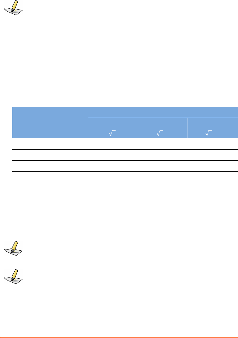
Note: These guidelines may not apply in all situations. Electromagnetic propagation is aected
by absorption and reection from structures, objects and people.
Recommended separation distance between portable and mobile RF
communications equipment and RGSC
The system is intended for use in an electromagnetic environment in which radiated
RF disturbances are controlled. The customer or the user of the system can help
prevent electromagnetic interference by maintaining a minimum distance between
portable and mobile RF communications equipment (transmiers) and the system as
recommended below, according to the maximum output power of the
communications equipment.
Table 7 Electromagnetic Compatibility (EMC, IEC 60601-1-2:2007, Table 6)
Rated Maximum Output
Power of Transmitter
W
Separation Distance According to Frequency of Transmitter [m]
150 kHz to 80 MHz
d= 0.35 P
80 MHz to 800 MHz
d= 0.35 P
800 MHz to 2.5 GHz
d= 0.7 P
0.01 0.04 0.04 0.07
0.1 0.11 0.11 0.22
1 0.35 0.35 0.70
10 1.11 1.11 2.21
100 3.50 3.50 7.00
For transmiers rated at a maximum output power not listed above, the
recommended separation distance d in meters (m) can be estimated using the
equation applicable to the frequency of the transmier, where P is the maximum
output power rating of the transmier in was (W) according to the transmier
manufacturer.
Note: At 80 MHz and 800 MHz, the separation distance for the higher frequency range
applies.
Note: These guidelines may not apply in all situations. Electromagnetic propagation is aected
by absorption and reection from structures, objects and people.
76
Draft (rco1321352456798 / Authoring:formal review / 11-Nov-2015 04:57 PST / asteinma)
Respiratory Gating for Scanners Instructions for Use

Visual Coaching Device WLAN Specifications
WLAN specications for wireless commnication between VCD and wireless access
point are as follows:
Type Specification
Frequency range 2400 MHz to 2485 MHz (802.11b/g)
Rated RF output 18 dBm
Modulation DSSS
Appendix B EMC Data and Guidance
Draft (rco1321352456798 / Authoring:formal review / 11-Nov-2015 04:57 PST / asteinma)
77

Index
4D scan 39
A
about
RGSC 7
this publication 7
access rights 60
acquire images
prospective gating 48
retrospective gating (4D) 49
alerts 36
amplitude gating 39
application
conguration 60
archive
conguration 69
auto-detect phase 55
auto-scale 47
B
baseline
drift 56
reference point 47
shift 56
breath-hold gating 39
breathing predictive lter 41
buons
camera 23
gating 49
home screen 18
C
cabinet
connectors 25
patch panel 25
units 24
wheels 24
calculation
phase and periodicity 53
calibrate 30
couch-mounted camera 30
wall-mounted / ceiling-mounted camera
31
camera 22
calibrate (couch-mounted) 30
calibrate (wall-mounted / ceiling-
mounted) 31
conguration 69
controls 23
mount (couch-mounted) 29
symbols 23
verify calibration (wall-mounted / ceiling-
mounted) 31
chart colors 50
clean
other equipment 28
reector block 28
client application 18
close
session 59
coaching modes 42
coaching speed 42, 46
colors 50
components 21
cabinet 24
camera 22
reector block 22
conguration
application 60
archive 69
camera 69
database 68
export 61
scanner 65
VCD 67
connectors 25
couch mount
camera 29
VCD 33
create
patient record 38
session 39
Curve 42
customer support 9
D
database
conguration 68
database (DB) mode 38
78
Draft (rco1321352456798 / Authoring:formal review / 11-Nov-2015 04:57 PST / asteinma)
Respiratory Gating for Scanners Instructions for Use

date of birth 39
default seings for gating 40
demo mode 44
DICOM export 57
Dog 42
E
electromagnetic compatibility
see EMC
electromagnetic interference
see EMI
emailing Varian customer support 9
EMC 71
emissions 72
immunity 72
test declarations and guidance 72
WLAN specications 77
EMI 71
enable visual patient motion monitoring 41
equipment
prepare 28
prepare the scanner 48
error messages 36
export
conguration 61
for 4D reconstruction (VXP) 58
for treatment (RPM/DICOM) 57
select start time (VXP) 58
F
le format
export le structure and format 63
le mode 38
nalize a session 55
rewall 24
Functionality limited 36
G
gating
prepare 37
gating buons 49
gating type for treatment 57
gating types 39
default seings 40
gating window 47
H
home screen 18
I
icons
symbols on labels 11
images
for 4D reconstruction 49
with amplitude gating 48
with breath-hold gating 48
with phase gating 48
with prospective gating 48
with retrospective gating 49
infrared detection 22
intended audience 7
intended use 7
L
layout 21
learning process
baseline 47
coaching speed 46
motion range 46
login 29
M
maintenance 15
maintenance mode 35
monitoring
breathing predictive lter 41
enable monitoring of visual patient
motion 41
periodicity meter 51
phase dial 50
respiratory trace 49
visual patient motion 52
motion range 42, 46
mount camera on couch 29
mount VCD on couch 33
MyVarian 9
N
network impact 14
network switch 24
New Scan / Open Scan 18
Index
Draft (rco1321352456798 / Authoring:formal review / 11-Nov-2015 04:57 PST / asteinma)
79

O
online customer support 9
open
patient record 38
session 39
ordering product documents by phone 9
P
patch panel 25
patient
open or create record 38
prepare 37
patient motion 41, 52
periodicity meter 51
phase
calculation 53
recalculation 55
phase dial 50
phase gating 39
place the reector block 45
prepare
equipment 28
gating 37
patient 37
scanner 48
session 37
preventive maintenance 15
prospective scan 39
R
Real-Time Unit 24
reector block 22
clean 28
prepare and place 45
requirements 15
resolve alerts 36
respiratory trace 49
restart learning 46
retrospective scan 39
review 55
export to DICOM 57
export to RPM 57
export to VXP 58
gating type for treatment 57
RGSC Messages 36
RPM export 57
S
safety
baery 13
network impact 14
overview 11
symbols on labels 11
system integrity 13
third-party devices 14
unauthorized hardware 14
unauthorized software 13
save
session 59
scaling 47
scan session 8
scan session workow
by workspace 18
scanner
conguration 65
service 15
session
close 55, 59
export 55
open or create 39
prepare equipment 28
prepare gating 37
prepare patient 37
review 55
sessions
training vs. scan 8
seings
prepare gating 37
shutdown 59
Slider 42
specications 15
backpointer laser 17
electrical 16
environmental 16
transport and storage 17
start learning 46
start time for VXP export 58
start/stop
gating 49
recording 49
startup 29
support e-mail addresses 9
symbols on labels 11
T
technical support 9
80
Draft (rco1321352456798 / Authoring:formal review / 11-Nov-2015 04:57 PST / asteinma)
Respiratory Gating for Scanners Instructions for Use

thresholds 47
training session 8
transport and storage 17
types of scans 39
default seings 40
U
user groups 60
user interface 19
V
Varian customer support 9
VCD
baery and charging station 27
baery safety 13
conguration 67
connectors 26
couch mount 33
demo mode 44
maintenance mode 35
operation 26
power on/o 34
recharge 34
WLAN specications 77
Verication / Calibration 31
verify calibration
wall-mounted / ceiling-mounted camera
31
visual coaching
prompt styles 42
Visual Coaching Device
see VCD
visual cues 9
visual prompt styles 42
VXP export 58
select start time 58
W
wheels 24
WLAN specications 77
workow
scan session (by workspace) 18
workspaces
home screen 18
New Scan / Open Scan 18
Workstation Unit 24
Index
Draft (rco1321352456798 / Authoring:formal review / 11-Nov-2015 04:57 PST / asteinma)
81