Vecima Networks AP5857 UNII Transmitter User Manual VCom manual
Vecima Networks Inc. UNII Transmitter VCom manual
UserManual.wiki
>
Vecima Networks
>
AP5857 User Manual
>
VCom manual
Contents
1.
VCom brochure
2.
VCom manual
VCom manual
Navigation menu
Upload a User Manual
Namespaces
Wiki Guide
HTML
PDF
Info
Views
User Manual
Discussion / Help
Navigation


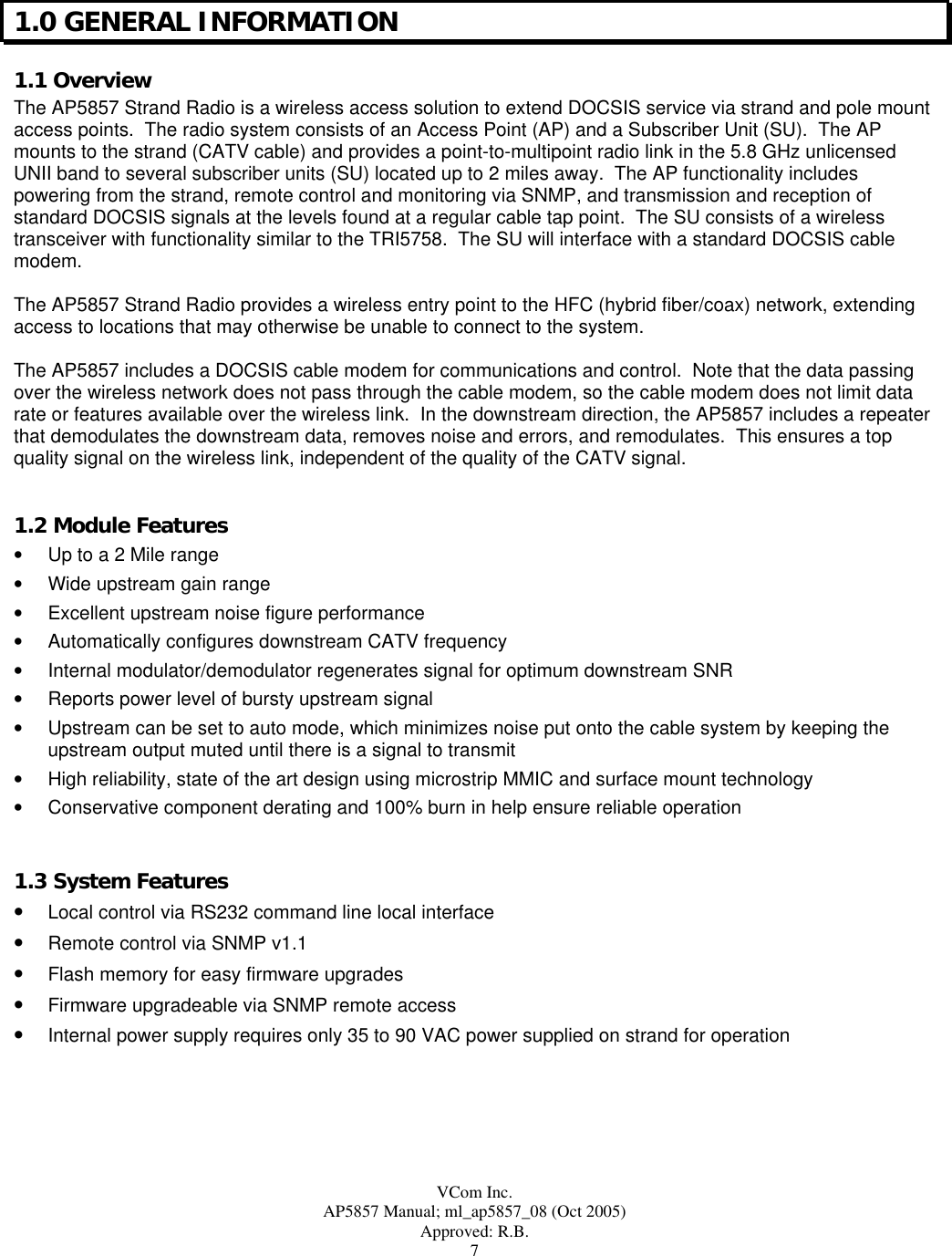
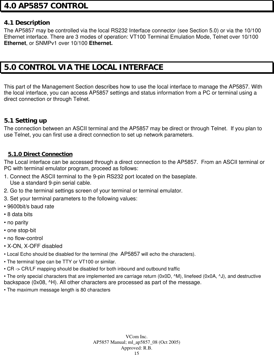
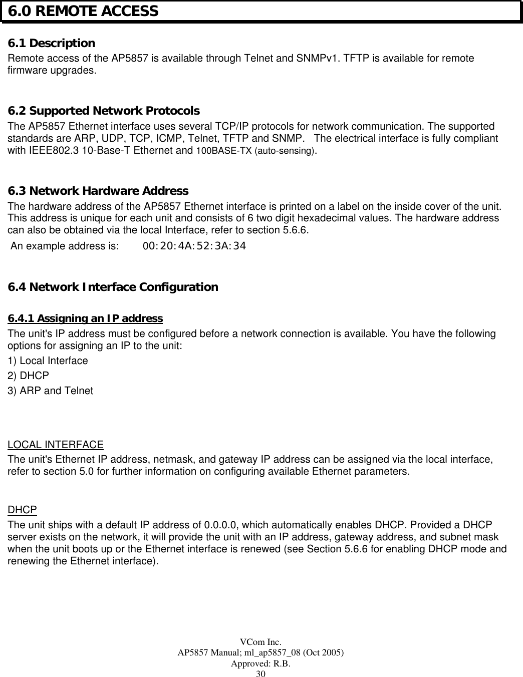
![VCom Inc. AP5857 Manual; ml_ap5857_08 (Oct 2005) Approved: R.B. 17 5.3 Timeout The local interface will time out after 5 minutes of inactivity and automatically return to the password> prompt. If accessing the unit via telnet, the session will disconnect. 5.4 The Main Menu Figure 5.3 Main Menu *** VCom Inc. AP5857 Main Menu ***1)Status Information2)Vendor Information3)Downstream Settings4)Upstream Settings5)General Settings6)Ethernet SettingsX)ExitENTER)RefreshSelect>_ 5.4.1 Interpreting the Main Menu The Main Menu shown in Figure 5.3, provides access for: • Status information • Downstream settings • Upstream settings • General settings • Ethernet settings 5.5 Using the Local Interface 5.5.1 Command Line Prompt The command line prompt consists of one of three forms: 1) Password prompt, Password> 2) Option prompt, Select> 3) Setting prompt, Setting [] ()>, see Modifying Settings From the Local Interface section below for details of setting prompt.](https://usermanual.wiki/Vecima-Networks/AP5857.VCom-manual/User-Guide-601160-Page-17.png)
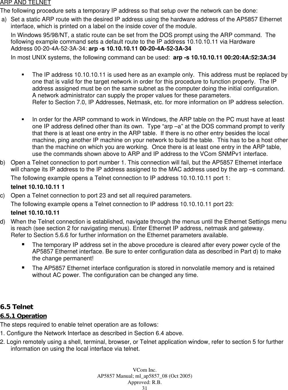
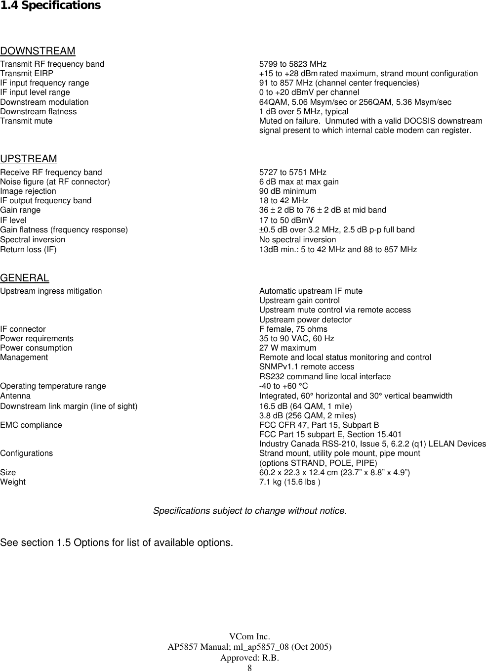
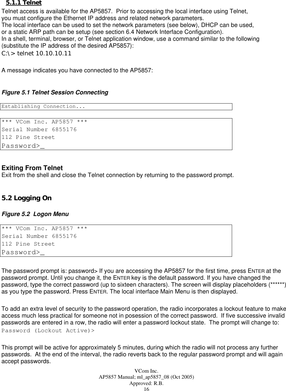
![VCom Inc. AP5857 Manual; ml_ap5857_08 (Oct 2005) Approved: R.B. 18 5.5.2 Entering Commands Commands can be entered in upper or lower case. To clear typed entries or an entry mistake and start again, press CONTROL-H or the backspace key to make corrections. If you enter an invalid value, the value will be rejected and the current menu and prompt will be displayed again. 5.5.3 Conventions Used The Local interface uses the following conventions: • Ranges of permitted values are depicted with square braces[]. • A letter or number followed by a parenthesis, 1), indicates a user-settable option. • Fields without a letter or number followed by a closed parenthesis, 1), are status/informational fields. 5.5.4 Exiting From the Local Interface You can exit every menu by using the X command. Each time you type “x”, you return to the next higher (previous) menu. At the Main Menu, typing X exits you from the local interface and logs you off. 5.5.5 Modifying Settings From the Local Interface Sub Menu items preceded by a letter or number followed by a parenthesis are user-settable options and allow that particular setting to be changed. Upon selecting desired setting, the local interface prompt will change to a setting prompt. A setting prompt consists of the setting name, the setting limits (shown in [] braces), and the current value (shown in () brackets). The new setting can be entered at the prompt or ENTER can be pressed to continue to use the current value. If a new setting is entered that is not within range of the limits specified, “Error” will be returned and the setting prompt will be displayed again. For example, the following figure illustrates entering an invalid Downstream Input Frequency: Figure 5.4 Setting Prompt Output Frequency [5802.000 to 5820.000 MHz](5811.000)>5790.000ErrorOutput Frequency [5802.000 to 5820.000 MHz](5811.000)>_ 5.6 Submenus From the Main Menu, other functions such as status and configuration are accessed through the submenus. 5.6.1 Status Information The Status Information Menu provides access to unit status and alarms. To access this menu from the Main Menu, type “1” to display the Status Information Menu.](https://usermanual.wiki/Vecima-Networks/AP5857.VCom-manual/User-Guide-601160-Page-18.png)
>_Enter the new frequency or press ENTER to use the current value. Downstream Output EIRP This setting allows the user to set the downstream output EIRP (Effective Isotropic Radiated Power). Valid levels are multiples of 0.5 dBm. If the level is within the setting limits but the step size is not correct, the level will be rounded to the nearest valid step size boundary To change the Downstream Output EIRP, type “2”. The local interface prompt will change to: Output EIRP[15.0 to 28.0 dBm](26.0) _Enter the new level or press ENTER to use the current value. Downstream Modulation This setting allows the user to set the downstream modulation to either 64QAM or 256QAM. Valid inputs are 64 or 256. To change the Downstream modulation, type “3”. The local interface prompt will change to: Downstream Modulation[64, 256 QAM](64) _Enter the new modulation or press ENTER to use the current value. Note that the symbol rate automatically set along with the modulation. Symbol rates are 5.05964 Msym/sec for 64QAM and 5.36054 Msym/sec for 256QAM. Downstream Interleaver](https://usermanual.wiki/Vecima-Networks/AP5857.VCom-manual/User-Guide-601160-Page-22.png)
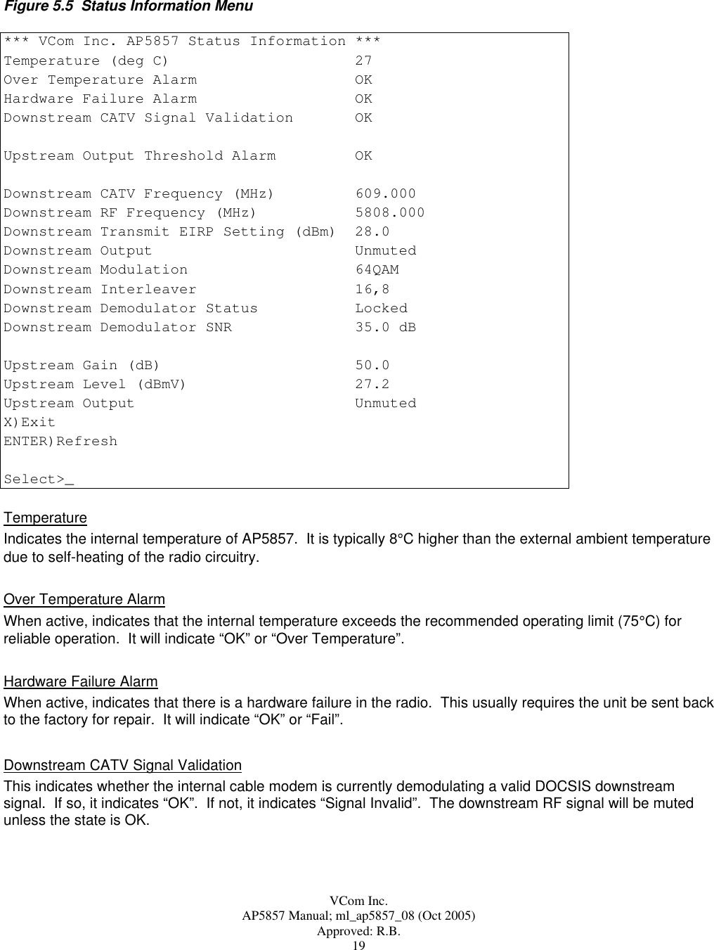
 _Enter the new interleaver length or press ENTER to use the current value. The values entered into the interleaver represent the I,J values in the convolutional interleaver. Longer lengths such as 128,1 provide more protection against burst errors since it spreads the errors out over a longer period of time, and it is more likely that the error correction can correct them. The cost is an increased delay time. For the longer interleaver depths, it is possible that the cable modem will be unable to lock due to delay limits set in the CMTS, so they should be used with caution. The AP5857 is shipped with the interleaver set to 16,8 which provides adequate protection while keeping delay low. Delays from the interleaver vary (for 64/256QAM) from 8/5.6 ms for 128,1 to 0.44/0.30 ms for 8,16. The cable modem at the subscriber side will automatically adjust to the selected interleaver value. Downstream Output Mute This setting allows the user to mute the downstream output. If the setting is set to muted, the output will remain muted until the setting is changed to “unmuted” and no alarm condition exists. To change the Downstream Output Mute state, type “4”. The local interface prompt will change to: Output Mute [0 unmute, 1 mute](1)>_Enter the new value or press ENTER to use the current value. Downstream CATV Frequency This indicates the center frequency of the downstream CATV channel to which the radio is tuned. This value is automatically configured by the radio to match the internal cable modem downstream frequency. Note that the value can not be changed directly by the user. The user may either let the internal cable modem lock on to a channel by itself, or the configuration file for the modem used by the CMTS may be written to direct the cable modem to a specific downstream channel. If the cable modem is not locked to a valid channel, the Input Frequency will indicate “No Channel” Downstream Demodulator Status Indicates the lock status of the downstream demodulator. It will display Locked or Not Locked. If the demodulator is not locked, this may indicate that there is no valid signal or the signal quality is too low for proper operation. Check also that the modulation (64QAM or 256QAM) is set to the correct value. Downstream Demodulator SNR Indicates the estimated downstream Signal to Noise Ratio as seen by the demodulator. The best signals will result in SNR values of 35 dB or more, however good operation will be maintained to SNR values of 30 dB or less. Lower SNR values indicate poor signal conditions, which may include interference or low signal level. The indicated SNR is an instantaneous reading, so the value of the SNR will vary from reading to reading.](https://usermanual.wiki/Vecima-Networks/AP5857.VCom-manual/User-Guide-601160-Page-23.png)
> _Enter the new gain or press ENTER to use the current value. Upstream Output Level This level gives an indication of the peak upstream output level. Because upstream signals are time-division multiplexed, the measured level is only valid while the signal is present. As a result, the peak measured level of the current signal will be latched and will remain the same until the signal is detected again. Upon detection of the new signal, the peak level will be measured and a new value returned. If a signal is not detected in 30 seconds, the value returned will remain unchanged, but will be marked “(Stale)” to indicate that a signal has not been detected in 30 seconds. The range of values returned is 17 dBmV to 50 dBmV. Upstream Output Mute This setting allows the user to set the upstream output mute state. There are three valid output states: Unmuted - force the output to be enabled, Muted – force the output to be disabled, Auto – output is controlled by system based upon received upstream signal level. Note: output mute setting will be overridden by active alarm conditions (i.e. output will be muted when an alarm condition is active) To change the Upstream Output Mute state, type “2”. The local interface prompt will change to: Output Mute [0 unmute, 1 mute, 2 auto](2)>_Enter the new value or press ENTER to use the current value. Upstream Output Auto Mute Threshold This setting allows the user to set the upstream output auto mute threshold level. When the upstream output state is set to “Auto” the detection circuitry will unmute the output when a level has been detected above the](https://usermanual.wiki/Vecima-Networks/AP5857.VCom-manual/User-Guide-601160-Page-24.png)
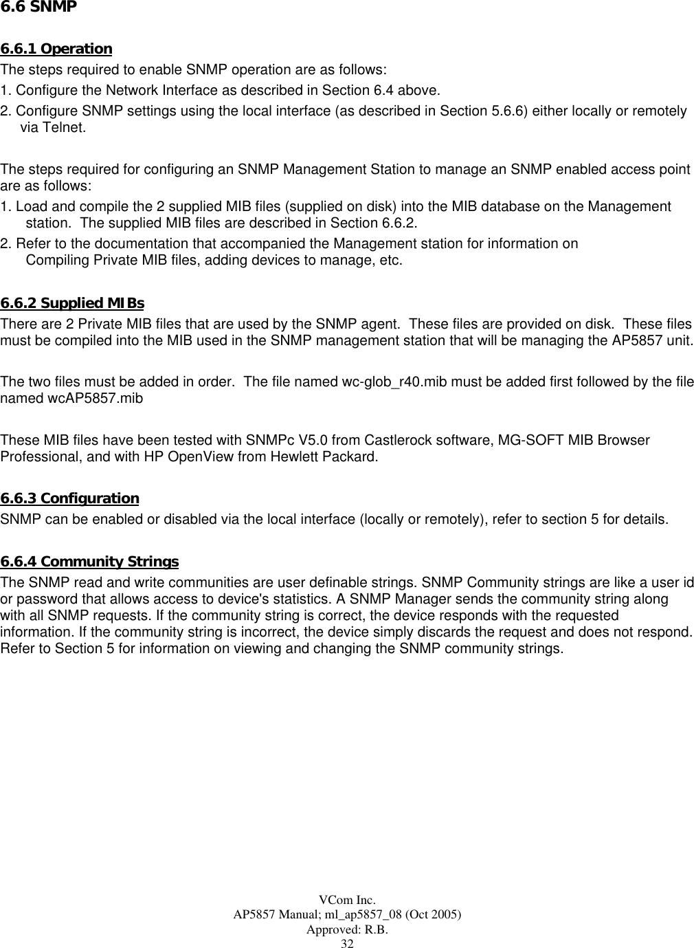
>_Enter the new threshold or press ENTER to use the current value. Upstream Output Alarm Threshold This setting allows the user to set the upstream output alarm threshold level. Thresholds are used to provide an alarm indication that the level is no longer within an acceptable range. Should the signal level exceed the specified threshold level, an alarm condition will be triggered and the upstream output muted. Valid levels are multiples of 0.5 dBmV. If the level is within the setting limits but the step size is not correct, the level will be rounded to the nearest valid step size boundary. To change the Upstream Output Alarm Threshold, type “3”. The local interface prompt will change to: Output Alarm Threshold [17.0 to 50.0 dBmV](40.0)>_Enter the new threshold or press ENTER to use the current value. It is recommended that the alarm threshold be set no less than 5 dB (and preferrably 10 dB or more) above the expected level of the upstream signal to accomodate expected CATV signal level variations. Upstream Output Alarm Threshold Enable This setting allows the user to enable threshold detection on the upstream output. Thresholds are used to provide an alarm indication that the level is no longer within an acceptable range. Should the signal level exceed the specified threshold level and threshold enabled, an alarm condition will be triggered and the upstream output muted. To change the Upstream Output Threshold Enable, type “4”. The local interface prompt will change to: Output Alarm Threshold Enable[0 disable, 1 enable](1)>_Enter the new values or press ENTER to use the current value. 5.6.5 General Settings The General Settings Menu provides access to the general settings and options. To access this menu from the Main Menu, type “5” to display the General Settings Menu. Figure 5.9 General Settings Menu *** VCom Inc. AP5857 General Settings ***1)Change Password ***2)User Message 112 Pine Street3)Upgrade Firmware4)Upgrade Modulator5)Reset Unit6)Load Factory DefaultsAntenna Gain (dB) 12.0X)ExitENTER)RefreshSelect>_](https://usermanual.wiki/Vecima-Networks/AP5857.VCom-manual/User-Guide-601160-Page-25.png)
>_Enter the new password or press ENTER to use the current value. If a new password is entered, the user will be prompted to re-enter the same password (for verification). Confirm Password [0 = empty string](***)>_The password may be a maximum of 16 characters long. User Message The user message is a user definable string that is displayed at the password menu. To change the user message, type “2”. The local interface prompt will change to: User Message [32 chars max](112 Pine Street)>_Enter the new message or press ENTER to use the current value. Upgrade Firmware The upgrade firmware menu option allows upgrading the application and bootloader flash areas via the local interface. Remote upgrades cannot be done through a telnet session but can be accomplished via TFTP over the 10/100 Ethernet interface. Note: Ethernet controller firmware can only be upgraded by TFTP. See section 6.7 for information on upgrading firmware via TFTP. To upgrade the firmware, type “3”. The local interface prompt will change to: Upgrade Firmware [Y/N](N)>_Upon selecting Yes, the unit will wait for the firmware image. The local interface prompt will change to: Waiting For Data [Ctrl-D to Abort]...>_From your terminal emulator program send the firmware file using Xmodem protocol with CRC or press CONTROL-D to abort. Upon successful upgrade, the unit will reset and the password> prompt will be displayed. Upgrade Modulator The upgrade Modulator menu option allows upgrading the firmware for the QAM modulator via the local interface. Remote upgrades cannot be done through a telnet session but can be accomplished via TFTP over the 10/100 Ethernet interface. Note: Ethernet controller firmware can only be upgraded by TFTP. See section 6.7 for information on upgrading firmware via TFTP. To upgrade the modulator, type “4”. The local interface prompt will change to: Upgrade Modulator [Y/N](N)>_Upon selecting Yes, the unit will wait for the modulator file. The local interface prompt will change to: Waiting For Data [Ctrl-D to Abort]...>_From your terminal emulator program send the firmware file using Xmodem protocol with CRC or press CONTROL-D to abort. Upon successful upgrade, the unit will reset and the password> prompt will be displayed. In general the firmware and modulator upgrades are independent unless it is otherwise indicated. That means that one may be upgraded without changing the other.](https://usermanual.wiki/Vecima-Networks/AP5857.VCom-manual/User-Guide-601160-Page-26.png)
>_Enter Yes to reset the unit or enter No or press ENTER to abort. Load Factory Defaults The Load Factory Defaults allows the user to put all the radio settings into a known state. The settings are: Vendor Information Vendor Name VCom Inc. Serial Number [system serial number] Model AP5857 Hardware Rev PC3B0105 [or as appropriate] Downstream Settings Output Frequency 5808 MHz Output EIRP 28 dBm Downstream Modulation 64QAM Downstream Interleaver 16,8 Output Mute 0 [unmuted] Upstream Settings Gain 50 dB Output Mute 0 [unmuted] Output Auto Mute Threshold 30 Output Alarm Threshold 50 Output Alarm Threshold Enable 0 [disabled] General Settings Password [no change] User Message [no change] Antenna Gain 12 Ethernet Settings SNMP Enable 1 [enabled]](https://usermanual.wiki/Vecima-Networks/AP5857.VCom-manual/User-Guide-601160-Page-27.png)
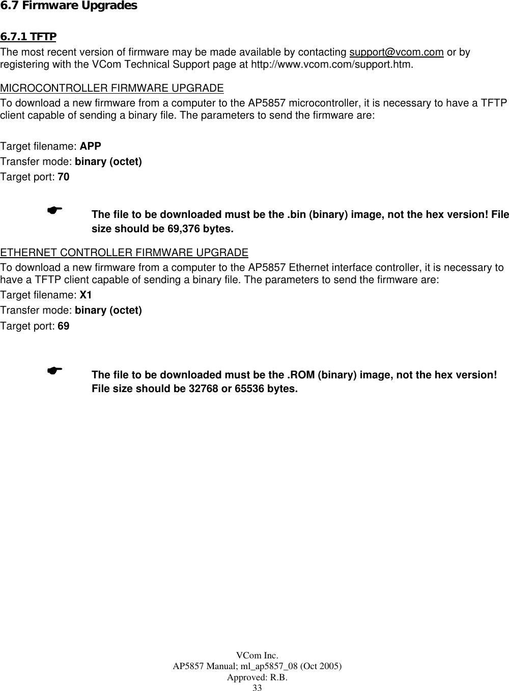
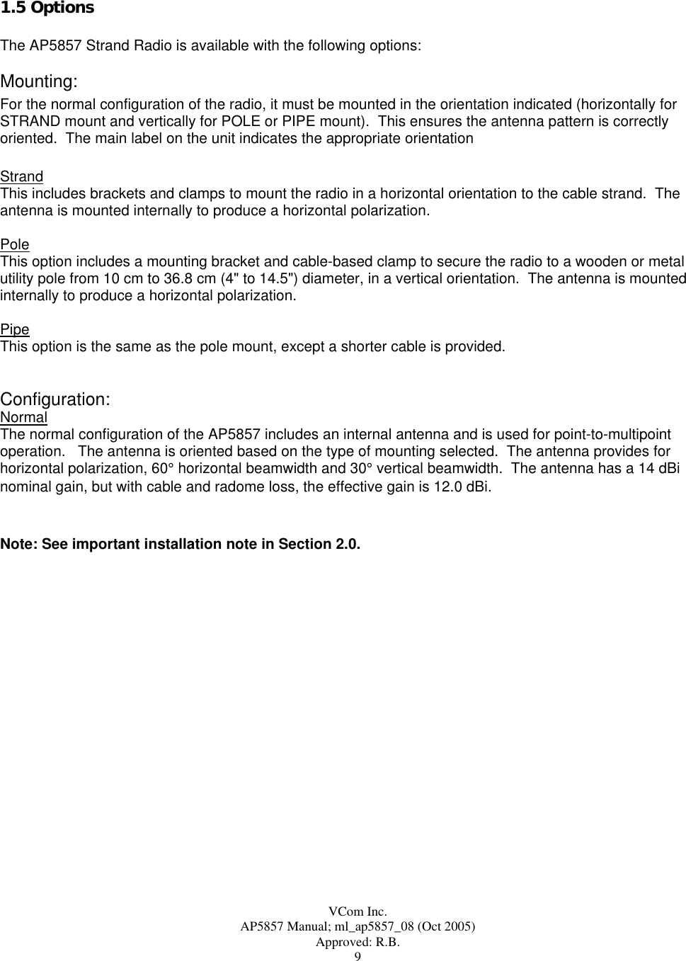
![VCom Inc. AP5857 Manual; ml_ap5857_08 (Oct 2005) Approved: R.B. 28 To load the factory defaults, “6”. The local interface prompt will change to: Load Factory Defaults [Y/N}(N)>_Enter Y to load factory defaults or press ENTER to select No. Antenna Gain The antenna gain line shows the current antenna gain. It is factory set to 12 dBi for the internal antenna and 32.4 dBi for the point-to-point antenna. These values reflect the effective gain and include cable and radome loss. The gain cannot be set by the user. 5.6.6 Ethernet Settings The Ethernet Settings Menu provides access to the Ethernet settings and options. To access this menu from the Main Menu, type “6” to display the Ethernet Settings Menu. Figure 5.10 Ethernet Settings Menu *** VCom Inc. AP5857 Ethernet Settings ***MAC Address 00:20:4A:52:3A:341)IP Address 10.10.10.112)Netmask 255.255.255.03)Gateway IP Address 10.10.10.104)Renew Ethernet Interface5)SNMP Enable Enabled6)SNMP Manager IP Address 10.10.10.107)SNMP Read Community public8)SNMP Write Community privateX)ExitENTER)RefreshSelect>_MAC Address This address is unique for each unit and consists of 6 two digit hexadecimal values. IP Address The IP address must be set to a unique value in your network. Refer to Section 4 if you are not familiar with IP addresses. If set to 0.0.0.0, DHCP mode is automatically enabled. Provided a DHCP server exists on the network, it will provide the unit with an IP address, gateway address, and subnet mask when the unit boots up. To change the IP address, type “1”. The local interface prompt will change to: IP Address [] (10.10.10.11)>_Enter the new IP address or press ENTER to use the current value.](https://usermanual.wiki/Vecima-Networks/AP5857.VCom-manual/User-Guide-601160-Page-28.png)
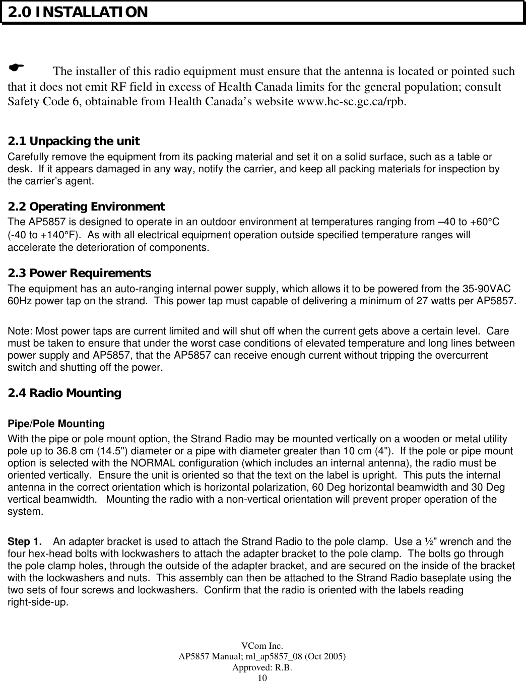
![VCom Inc. AP5857 Manual; ml_ap5857_08 (Oct 2005) Approved: R.B. 29 Netmask A netmask defines how many bits from the IP address are to be taken as the network part and how many bits are to be taken as the host part (reminder: standard class A 8/24 (net/host), class B 16/16, class C 24/8 bits). The netmask is shown in standard format “255.255.xxx.xxx“. To change the Gateway IP address, type “2”. The local interface prompt will change to: Netmask [] (255.255.255.0)>_Enter the new netmask or press ENTER to use the current value. Gateway IP Address The router/gateway address is needed to communicate to other LAN segments. The default gateway must be set to address the router that connects these segments. This address must be within the local network. If in doubt, your network administrator should be consulted. To change the Gateway IP address, type “3”. The local interface prompt will change to: Gateway IP Address [] (10.10.10.10)>_Enter the new IP address or press ENTER to use the current value. Renew Ethernet Interface In order to activate any changes to the Ethernet settings, the interface needs to be restarted. To Renew the Ethernet Interface, type “4”. The local interface prompt will change to: Renew Ethernet Interface [Y/N](N)>_Enter Yes to renew the Ethernet interface or enter No or press ENTER to abort. SNMP Manager IP Address The SNMP manager IP address. This address is used to send SNMP traps. To change the SNMP Manager IP address, type “5”. The local interface prompt will change to: SNMP Manager IP Address [] (10.10.10.10)>_Enter the new IP address or press ENTER to use the current value. SNMP Read Community To change the SNMP read community string, type “6”. The local interface prompt will change to: SNMP Read Community [32 chars max] (public)>_Enter the new community string or press ENTER to use the current value. SNMP Write Community To change the SNMP write community string, type “7”. The local interface prompt will change to: SNMP Write Community [32 chars max] (private)>_ Enter the new community string or press ENTER to use the current value.](https://usermanual.wiki/Vecima-Networks/AP5857.VCom-manual/User-Guide-601160-Page-29.png)