Vecima Networks AP5857 UNII Transmitter User Manual VCom manual
Vecima Networks Inc. UNII Transmitter VCom manual
Contents
- 1. VCom brochure
- 2. VCom manual
VCom manual

INSTALLATION AND OPERATION GUIDE
FOR SYSTEM OPERATORS

VCom Inc.
AP5857 Manual; ml_ap5857_08 (Oct 2005)
Approved: R.B.
2
Proprietary to VCom Inc.
All rights reserved.
No part of this publication may by reproduced in any form or by any means or used to make any derivative work (such as translation,
transformation or adaptation) without written permission from VCom Inc.
VCom Inc. reserves the right to revise this publication and to make changes in content from time to time without obligation on the part of
VCom Inc. to provide notification of such revision or change.
VCom Inc. provides this guide without warranty of any kind, either implied or expressed, including, but not limited to, the implied
warranties of merchantability and fitness for a particular purpose. VCom Inc. may make improvements or changes in the product(s)
described in this manual at any time.
AP5857 Manual; ml_ap5857_08 (Oct 2005) Approved: R.B.
Specifications subject to change without notice — Printed in Canada

VCom Inc.
AP5857 Manual; ml_ap5857_08 (Oct 2005)
Approved: R.B.
3
Thank-you for purchasing this product
and welcome to VCom!
You have chosen an innovative solution from a leading technology
design center in the ongoing TV & data delivery revolution.
No doubt you’ve been thinking that the future of your television delivery system includes new technologies
such as Digital TV, Internet Over Cable, Wireless Cable. By selecting VCom, you are benefiting from the
same design powerhouse that since 1988 has created custom RF and digital products for technology leaders
such as AT&T, Cisco Systems, Cogeco, Comcast, and Cox Communications.
VCom Inc. designs and manufactures:
Agile CATV Modulators
256 QAM Upconverters
Digital Video Modulators
Frequency Translators
Spread Spectrum Devices
MMDS Transceivers
Off Air/CATV Demodulators
Wireless Cable MMDS
Wireless Cable LMDS
Video On Demand Products
and more! Designs to fill the market needs of the CATV industry – both foreign and domestic.
For additional product or corporate information, contact us:
On the web at: www.vcom.com
By sending email to: sales@vcom.com
By telephone: (306) 955-7075
By fax: (306) 955-9919
By snail mail: VCom Inc.
150 Cardinal Place
Saskatoon, SK Canada S7L 6H7
VCom Inc.'s Corporate Mandate
is to be a leading worldwide designer and manufacturer of state-of-the-
art communications equipment and components. Through the
remarkable success of our customers and business partners,
VCom innovations are achieving this goal.

VCom Inc.
AP5857 Manual; ml_ap5857_08 (Oct 2005)
Approved: R.B.
4
SAFETY PRECAUTIONS
1. Before installing and operating this equipment, read all Safety, Installation and Operating sections. Retain
this manual for future reference.
2. Follow all instructions — Failure to do so may result in damage to the unit or severe personal injury.
3. Servicing should not be attempted by the user. There are no user serviceable parts inside. Refer all
servicing to factory qualified personnel.
4. Shock Hazard — An electrical shock hazard exists when the chassis cover is removed as is required to set
internal controls. Always disconnect power from the unit before removing the cover.
5. Cleaning — Do not use liquid or aerosol cleaners. Use a damp cloth for cleaning.
LES PRÉCAUTIONS DE SÉCURITÉ
1. Avant d'installer ou d'opérer cet équipement, lisez, toutes les sections de sécurités, d'installations et
d'opérations. Gardez ce manuel comme source de référence.
2. Suivez toutes instructions - si non, vous risquez d'endommager la machine ou de vous blesser
sérieusement.
3. N'essayez, pas de réparer cet équipement vous même. Référez toutes revisions nécessaire au personnel
qualifié de la manufacture.
4. Risque de choc - Il y a un risque de décharge électrique qui existe quand la couverture du châssis est
enlevée, comme est nécessaire pour ajuster les contrôlcs internes. Il faut toujours couper l'électricité avant
d'enlever le couvercle pour faire aucun ajustage.
5. Le nettoyage - n'utilisez pas de nettoyeurs aérosols ou liquides. Utilisez un tissu humide pour nettoyer.
Caution: To comply with FCC RF exposure limits in Section 1.1307, the AP5857
requires a minimum distance of 0.2 meters between it and all persons.
Modifications not expressly approved by the manufacturer may void the user’s
authority to operate this equipment.
This device complies with FCC Part 15, Subparts B and E.
This device complies with Industry Canada RSS 210, Issue 5 including Amendments 1, 2, 3, and 4.
Important Installation Instructions
VCom Inc.
AP5857 Manual; ml_ap5857_08 (Oct 2005)
Approved: R.B.
5
INDEX
1.0 GENERAL INFORMATION
............................................................7
1.1 Overview ..................................................................................................................................................7
1.2 Module Features......................................................................................................................................7
1.3 System Features.......................................................................................................................................7
1.4 Specifications...........................................................................................................................................8
1.5 Options.....................................................................................................................................................9
2.0 INSTALLATION
.........................................................................10
2.1 Unpacking the unit................................................................................................................................10
2.2 Operating Environment........................................................................................................................10
2.3 Power Requirements.............................................................................................................................10
2.4 Radio Mounting.....................................................................................................................................10
3.0 CONNECTORS & CONFIGURATION
...........................................13
3.1 AP5857 Connection...............................................................................................................................13
3.2 AP5857 Configuration ..........................................................................................................................13
4.0 AP5857 CONTROL
.....................................................................15
4.1 Description.............................................................................................................................................15
5.0 CONTROL VIA THE LOCAL INTERFACE
......................................15
5.1 Setting up ...............................................................................................................................................15
5.1.0 Direct Connection.......................................................................................................................................... 15
5.1.1 Telnet .............................................................................................................................................................. 16
5.2 Logging On ............................................................................................................................................16
5.3 Timeout ..................................................................................................................................................17
5.4 The Main Menu.....................................................................................................................................17
5.5 Using the Local Interface......................................................................................................................17
5.6 Submenus...............................................................................................................................................18
6.0 REMOTE ACCESS
.......................................................................30
6.1 Description.............................................................................................................................................30
VCom Inc.
AP5857 Manual; ml_ap5857_08 (Oct 2005)
Approved: R.B.
6
6.2 Supported Network Protocols..............................................................................................................30
6.3 Network Hardware Address ................................................................................................................30
6.4 Network Interface Configuration........................................................................................................30
6.5 Telnet......................................................................................................................................................31
6.6 SNMP .....................................................................................................................................................32
6.7 Firmware Upgrades ..............................................................................................................................33
7.0 IP ADDRESSES, NETMASK, ETC
.................................................34
7.1 IP Addressing ........................................................................................................................................34
7.2 Network Address...................................................................................................................................35
7.3 Broadcast Address ................................................................................................................................35
7.4 IP Netmask.............................................................................................................................................35
7.5 Private IP networks and the Internet..................................................................................................35
7.6 Network RFC’s......................................................................................................................................35
8.0 WARRANTY AND SERVICE POLICY
...........................................36
8.1 Warranty Statement .............................................................................................................................36
8.2 Service Policies: How to Return an Item for Service:........................................................................36
8.3 Repair Charges and Warranty Exemptions.......................................................................................37

VCom Inc.
AP5857 Manual; ml_ap5857_08 (Oct 2005)
Approved: R.B.
7
1.0 GENERAL INFORMATION
1.1 Overview
The AP5857 Strand Radio is a wireless access solution to extend DOCSIS service via strand and pole mount
access points. The radio system consists of an Access Point (AP) and a Subscriber Unit (SU). The AP
mounts to the strand (CATV cable) and provides a point-to-multipoint radio link in the 5.8 GHz unlicensed
UNII band to several subscriber units (SU) located up to 2 miles away. The AP functionality includes
powering from the strand, remote control and monitoring via SNMP, and transmission and reception of
standard DOCSIS signals at the levels found at a regular cable tap point. The SU consists of a wireless
transceiver with functionality similar to the TRI5758. The SU will interface with a standard DOCSIS cable
modem.
The AP5857 Strand Radio provides a wireless entry point to the HFC (hybrid fiber/coax) network, extending
access to locations that may otherwise be unable to connect to the system.
The AP5857 includes a DOCSIS cable modem for communications and control. Note that the data passing
over the wireless network does not pass through the cable modem, so the cable modem does not limit data
rate or features available over the wireless link. In the downstream direction, the AP5857 includes a repeater
that demodulates the downstream data, removes noise and errors, and remodulates. This ensures a top
quality signal on the wireless link, independent of the quality of the CATV signal.
1.2 Module Features
• Up to a 2 Mile range
• Wide upstream gain range
• Excellent upstream noise figure performance
• Automatically configures downstream CATV frequency
• Internal modulator/demodulator regenerates signal for optimum downstream SNR
• Reports power level of bursty upstream signal
• Upstream can be set to auto mode, which minimizes noise put onto the cable system by keeping the
upstream output muted until there is a signal to transmit
• High reliability, state of the art design using microstrip MMIC and surface mount technology
• Conservative component derating and 100% burn in help ensure reliable operation
1.3 System Features
• Local control via RS232 command line local interface
• Remote control via SNMP v1.1
• Flash memory for easy firmware upgrades
• Firmware upgradeable via SNMP remote access
• Internal power supply requires only 35 to 90 VAC power supplied on strand for operation

VCom Inc.
AP5857 Manual; ml_ap5857_08 (Oct 2005)
Approved: R.B.
8
1.4 Specifications
DOWNSTREAM
Transmit RF frequency band 5799 to 5823 MHz
Transmit EIRP +15 to +28 dBm rated maximum, strand mount configuration
IF input frequency range 91 to 857 MHz (channel center frequencies)
IF input level range 0 to +20 dBmV per channel
Downstream modulation 64QAM, 5.06 Msym/sec or 256QAM, 5.36 Msym/sec
Downstream flatness 1 dB over 5 MHz, typical
Transmit mute Muted on failure. Unmuted with a valid DOCSIS downstream
signal present to which internal cable modem can register.
UPSTREAM
Receive RF frequency band 5727 to 5751 MHz
Noise figure (at RF connector) 6 dB max at max gain
Image rejection 90 dB minimum
IF output frequency band 18 to 42 MHz
Gain range 36 ± 2 dB to 76 ± 2 dB at mid band
IF level 17 to 50 dBmV
Gain flatness (frequency response) ±0.5 dB over 3.2 MHz, 2.5 dB p-p full band
Spectral inversion No spectral inversion
Return loss (IF) 13dB min.: 5 to 42 MHz and 88 to 857 MHz
GENERAL
Upstream ingress mitigation Automatic upstream IF mute
Upstream gain control
Upstream mute control via remote access
Upstream power detector
IF connector F female, 75 ohms
Power requirements 35 to 90 VAC, 60 Hz
Power consumption 27 W maximum
Management Remote and local status monitoring and control
SNMPv1.1 remote access
RS232 command line local interface
Operating temperature range -40 to +60 °C
Antenna Integrated, 60° horizontal and 30° vertical beamwidth
Downstream link margin (line of sight) 16.5 dB (64 QAM, 1 mile)
3.8 dB (256 QAM, 2 miles)
EMC compliance FCC CFR 47, Part 15, Subpart B
FCC Part 15 subpart E, Section 15.401
Industry Canada RSS-210, Issue 5, 6.2.2 (q1) LELAN Devices
Configurations Strand mount, utility pole mount, pipe mount
(options STRAND, POLE, PIPE)
Size 60.2 x 22.3 x 12.4 cm (23.7” x 8.8” x 4.9”)
Weight 7.1 kg (15.6 lbs )
Specifications subject to change without notice.
See section 1.5 Options for list of available options.

VCom Inc.
AP5857 Manual; ml_ap5857_08 (Oct 2005)
Approved: R.B.
9
1.5 Options
The AP5857 Strand Radio is available with the following options:
Mounting:
For the normal configuration of the radio, it must be mounted in the orientation indicated (horizontally for
STRAND mount and vertically for POLE or PIPE mount). This ensures the antenna pattern is correctly
oriented. The main label on the unit indicates the appropriate orientation
Strand
This includes brackets and clamps to mount the radio in a horizontal orientation to the cable strand. The
antenna is mounted internally to produce a horizontal polarization.
Pole
This option includes a mounting bracket and cable-based clamp to secure the radio to a wooden or metal
utility pole from 10 cm to 36.8 cm (4" to 14.5") diameter, in a vertical orientation. The antenna is mounted
internally to produce a horizontal polarization.
Pipe
This option is the same as the pole mount, except a shorter cable is provided.
Configuration:
Normal
The normal configuration of the AP5857 includes an internal antenna and is used for point-to-multipoint
operation. The antenna is oriented based on the type of mounting selected. The antenna provides for
horizontal polarization, 60° horizontal beamwidth and 30° vertical beamwidth. The antenna has a 14 dBi
nominal gain, but with cable and radome loss, the effective gain is 12.0 dBi.
Note: See important installation note in Section 2.0.

VCom Inc.
AP5857 Manual; ml_ap5857_08 (Oct 2005)
Approved: R.B.
10
2.0 INSTALLATION
The installer of this radio equipment must ensure that the antenna is located or pointed such
that it does not emit RF field in excess of Health Canada limits for the general population; consult
Safety Code 6, obtainable from Health Canada’s website www.hc-sc.gc.ca/rpb.
2.1 Unpacking the unit
Carefully remove the equipment from its packing material and set it on a solid surface, such as a table or
desk. If it appears damaged in any way, notify the carrier, and keep all packing materials for inspection by
the carrier’s agent.
2.2 Operating Environment
The AP5857 is designed to operate in an outdoor environment at temperatures ranging from –40 to +60°C
(-40 to +140°F). As with all electrical equipment operation outside specified temperature ranges will
accelerate the deterioration of components.
2.3 Power Requirements
The equipment has an auto-ranging internal power supply, which allows it to be powered from the 35-90VAC
60Hz power tap on the strand. This power tap must capable of delivering a minimum of 27 watts per AP5857.
Note: Most power taps are current limited and will shut off when the current gets above a certain level. Care
must be taken to ensure that under the worst case conditions of elevated temperature and long lines between
power supply and AP5857, that the AP5857 can receive enough current without tripping the overcurrent
switch and shutting off the power.
2.4 Radio Mounting
Pipe/Pole Mounting
With the pipe or pole mount option, the Strand Radio may be mounted vertically on a wooden or metal utility
pole up to 36.8 cm (14.5") diameter or a pipe with diameter greater than 10 cm (4"). If the pole or pipe mount
option is selected with the NORMAL configuration (which includes an internal antenna), the radio must be
oriented vertically. Ensure the unit is oriented so that the text on the label is upright. This puts the internal
antenna in the correct orientation which is horizontal polarization, 60 Deg horizontal beamwidth and 30 Deg
vertical beamwidth. Mounting the radio with a non-vertical orientation will prevent proper operation of the
system.
Step 1. An adapter bracket is used to attach the Strand Radio to the pole clamp. Use a ½” wrench and the
four hex-head bolts with lockwashers to attach the adapter bracket to the pole clamp. The bolts go through
the pole clamp holes, through the outside of the adapter bracket, and are secured on the inside of the bracket
with the lockwashers and nuts. This assembly can then be attached to the Strand Radio baseplate using the
two sets of four screws and lockwashers. Confirm that the radio is oriented with the labels reading
right-side-up.
VCom Inc.
AP5857 Manual; ml_ap5857_08 (Oct 2005)
Approved: R.B.
11
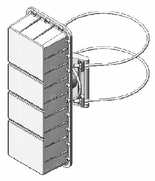
Step 2. A cable is used to strap the radio mount to the pole or pipe. First loosen the two 4-bolt clamps near
the loop end of the cable so the cable can slide free through them. Wrap the two ends of the cable around
the pole or pipe and place the ends in the two notched sections of the mount. Then pull the loop end of the
cable to take up any slack and tighten the two 4-bolt clamps with a ½” wrench to secure the cable. The nuts
at the ends of the cable can then be tightened using a 5/8” wrench to cinch the cable around the pole or pipe
to the desired tension. If necessary, adjust the bracket rotation using the 5/8” wrench on the two bolt heads.
Ensure all bolts are tight and the cable loop will not rattle against the unit in windy conditions. If the latter is a
problem, secure the loop of the cable to one of the ends of the cable with a cable-tie.
Figure 2.1 shows the AP5857 with cables attached.
Figure 2.1 AP5857 Pipe or Pole Mounting
Strand Mounting
There are two mounting brackets supplied. These are to be installed on the back of the AP5857 using the
supplied screws and lockwashers. With the brackets installed to the AP5857, secure the AP5857 to the
strand using the two clamps provided. See figure 2.2 for details.

VCom Inc.
AP5857 Manual; ml_ap5857_08 (Oct 2005)
Approved: R.B.
12
Figure 2.2 AP5857 Strand Mounting
Note that if the strand mount option is selected for the radio along with internal antenna, the radio must be
mounted horizontally on the strand as shown.

VCom Inc.
AP5857 Manual; ml_ap5857_08 (Oct 2005)
Approved: R.B.
13
3.0 CONNECTORS & CONFIGURATION
3.1 AP5857 Connection
The only required connection to the AP5857 is made through the F-connector. Connect the coaxial cable
from the powered tap to the F connector of the AP5857.
Note the power and voltage requirements as mentioned in the Power Requirements section.
3.2 AP5857 Configuration
The AP5857 status and configuration may be monitored and modified either remotely through an Ethernet
connection via the cable, or locally via the local interface. For local control of the radio, use the 9-pin RS232
local interface located on the baseplate of the unit, with settings as described in the Direct Connection section
of this manual.
Since the AP5857 is capable of providing a wide range of upstream gains and downstream transmit levels,
the setting of these levels is very important to maintain optimum performance.
The downstream frequency of the radio is automatically configured by the radio to match the
internal cable modem downstream frequency. Note that the downstream frequency cannot be set directly by
the user. The user may either let the internal cable modem lock on to a channel by itself, or the configuration
file for the modem used by the CMTS may be written to direct the cable modem to a specific downstream
channel.
3.2.1 Downstream Transmit EIRP
The downstream transmit EIRP is normally set to the maximum value of 28 dBm EIRP. For very short
distances, the transmit power should be reduced to prevent overdriving of the CM at the customer site.
When operating normally, the status will show the downstream output as “Unmuted”. The AP5857
automatically mutes if there is a problem such as the internal cable modem unable to register on the system,
no valid signal for the downstream demodulator, or a hardware problem indicated by a hardware alarm. It
will indicate “Muted (Alarm)” under these conditions. If it shows “Muted (Manual)”, this indicates that the
output has been manually muted by the user. It can be unmuted in the downstream menu.
The downstream power may also be adjusted to optimize subscriber CM receive SNR if desired. On all but
the longest links, reducing the transmit EIRP by a few dB may improve downstream receive SNR by
improving transmit linearity.

VCom Inc.
AP5857 Manual; ml_ap5857_08 (Oct 2005)
Approved: R.B.
14
3.2.2 Upstream Gain
The upstream gain setting is used both to compensate for the link distances and to enable the upstream
signal to meet the required level into the tap. Note that the broadband noise level in the 18 to 42 MHz
upstream band is directly proportional to the upstream gain setting, so in general it is desirable to operate with
the lowest practical gain setting to minimize the noise level.
On the setup of at least the first RF link to the AP5857, the setup should be performed
with the Upstream Mute set to “Unmute”, and the Output Alarm Threshold set to “Disable” so that
the upstream signal is continuously on. This will simplify the setup.
It is recommended that the upstream gain be set to approximately 50 dB for initial setup. Since some taps
may require higher upstream levels than this will produce, the CM may not be able to register with the initial
gain settings. If that is the case, the upstream gain can be increased in 10 dB increments until the subscriber
CM registers, allowing time for registration at each gain.
When registration is achieved, the upstream gain should be optimized by setting it to a value that has the
subscriber CM transmitting between 40 dBmV and 50 dBmV. The optimal gain setting for a specific link will
depend on both the link distance and the upstream level required at the tap. Lower upstream gain settings
will cause the CM to transmit harder to maintain the same level at the tap. This may improve the
signal-to-noise ratio (SNR), but will also reduce margin to compensate for gain variations in the path between
the CM and the CMTS. Conversely, higher upstream gains will cause the subscriber CM to reduce it’s
transmit power to maintain the same level at the tap, and this may degrade the upstream SNR.
3.2.3 Upstream Muting
The upstream muting has three modes, which include Unmuted, Muted and Automatic.
The Unmuted setting should be used for initial setup and may also be used for normal operation. In this
mode, the upstream output is always on.
The Muted setting is used to manually turn off the AP5857 upstream signal. This may be used for example if
the unit is put out of service. Manually muting the upstream output does not affect the internal cable modem,
so communications and control are unaffected.
The Automatic Mute setting may be used to reduce the impact of the upstream noise on the cable system.
In the automatic mute mode, the upstream output is muted unless there is a signal above the Output Auto
Mute Threshold level. When a signal above the threshold is detected, the upstream output is turned on only
for the duration of the upstream burst. The Output Level reading in the Upstream Settings group indicates the
approximate measured level of the upstream burst signal. The threshold is typically set near that level or up
to a few dB lower. The threshold setting is important since if the threshold is set too low, noise may keep the
output unmuted, while setting the threshold too high will not allow the signal to turn on the output.
Note that there is more latitude in setting the threshold if the AP5857 upstream output is higher. The range
between highest and lowest threshold setting at +50 dBmV output is approximately 7 dB, but only 3 dB at +35
dBmV. The automatic muting is not recommended for upstream output levels below 35 dBmV.

VCom Inc.
AP5857 Manual; ml_ap5857_08 (Oct 2005)
Approved: R.B.
15
4.0 AP5857 CONTROL
4.1 Description
The AP5857 may be controlled via the local RS232 Interface connector (see Section 5.0) or via the 10/100
Ethernet interface. There are 3 modes of operation: VT100 Terminal Emulation Mode, Telnet over 10/100
Ethernet, or SNMPv1 over 10/100 Ethernet.
5.0 CONTROL VIA THE LOCAL INTERFACE
This part of the Management Section describes how to use the local interface to manage the AP5857. With
the local interface, you can access AP5857 settings and status information from a PC or terminal using a
direct connection or through Telnet.
5.1 Setting up
The connection between an ASCII terminal and the AP5857 may be direct or through Telnet. If you plan to
use Telnet, you can first use a direct connection to set up network parameters.
5.1.0 Direct Connection
The Local interface can be accessed through a direct connection to the AP5857. From an ASCII terminal or
PC with terminal emulator program, proceed as follows:
1. Connect the ASCII terminal to the 9-pin RS232 port located on the baseplate.
Use a standard 9-pin serial cable.
2. Go to the terminal settings screen of your terminal or terminal emulator.
3. Set your terminal parameters to the following values:
• 9600bit/s baud rate
• 8 data bits
• no parity
• one stop-bit
• no flow-control
• X-ON, X-OFF disabled
• Local Echo should be disabled for the terminal (the AP5857 will echo the characters).
• The terminal type can be TTY or VT100 or similar.
• CR -> CR/LF mapping should be disabled for both inbound and outbound traffic
• The only special characters that are implemented are carriage return (0x0D, ^M), linefeed (0x0A, ^J), and destructive
backspace (0x08, ^H). All other characters are processed as part of the message.
• The maximum message length is 80 characters

VCom Inc.
AP5857 Manual; ml_ap5857_08 (Oct 2005)
Approved: R.B.
16
5.1.1 Telnet
Telnet access is available for the AP5857. Prior to accessing the local interface using Telnet,
you must configure the Ethernet IP address and related network parameters.
The local interface can be used to set the network parameters (see below), DHCP can be used,
or a static ARP path can be setup (see section 6.4 Network Interface Configuration).
In a shell, terminal, browser, or Telnet application window, use a command similar to the following
(substitute the IP address of the desired AP5857):
C:\> telnet 10.10.10.11
A message indicates you have connected to the AP5857:
Figure 5.1 Telnet Session Connecting
Establishing Connection...
*** VCom Inc. AP5857 ***
Serial Number 6855176
112 Pine Street
Password>_
Exiting From Telnet
Exit from the shell and close the Telnet connection by returning to the password prompt.
5.2 Logging On
Figure 5.2 Logon Menu
*** VCom Inc. AP5857 ***
Serial Number 6855176
112 Pine Street
Password>_
The password prompt is: password> If you are accessing the AP5857 for the first time, press ENTER at the
password prompt. Until you change it, the ENTER key is the default password. If you have changed the
password, type the correct password (up to sixteen characters). The screen will display placeholders (******)
as you type the password. Press ENTER. The local interface Main Menu is then displayed.
To add an extra level of security to the password operation, the radio incorporates a lockout feature to make
access much less practical for someone not in posession of the correct password. If five successive invalid
passwords are entered in a row, the radio will enter a password lockout state. The prompt will change to:
Password (Lockout Active)>
This prompt will be active for approximately 5 minutes, during which the radio will not process any further
passwords. At the end of the interval, the radio reverts back to the regular password prompt and will again
accept passwords.

VCom Inc.
AP5857 Manual; ml_ap5857_08 (Oct 2005)
Approved: R.B.
17
5.3 Timeout
The local interface will time out after 5 minutes of inactivity and automatically return to the password> prompt.
If accessing the unit via telnet, the session will disconnect.
5.4 The Main Menu
Figure 5.3 Main Menu
*** VCom Inc. AP5857 Main Menu ***
1)Status Information
2)Vendor Information
3)Downstream Settings
4)Upstream Settings
5)General Settings
6)Ethernet Settings
X)Exit
ENTER)Refresh
Select>_
5.4.1 Interpreting the Main Menu
The Main Menu shown in Figure 5.3, provides access for:
• Status information
• Downstream settings
• Upstream settings
• General settings
• Ethernet settings
5.5 Using the Local Interface
5.5.1 Command Line Prompt
The command line prompt consists of one of three forms:
1) Password prompt, Password>
2) Option prompt, Select>
3) Setting prompt, Setting [] ()>, see Modifying Settings From the Local Interface section below for details of
setting prompt.

VCom Inc.
AP5857 Manual; ml_ap5857_08 (Oct 2005)
Approved: R.B.
18
5.5.2 Entering Commands
Commands can be entered in upper or lower case.
To clear typed entries or an entry mistake and start again, press CONTROL-H or the backspace key to make
corrections.
If you enter an invalid value, the value will be rejected and the current menu and prompt will be displayed
again.
5.5.3 Conventions Used
The Local interface uses the following conventions:
• Ranges of permitted values are depicted with square braces[].
• A letter or number followed by a parenthesis, 1), indicates a user-settable option.
• Fields without a letter or number followed by a closed parenthesis, 1), are status/informational
fields.
5.5.4 Exiting From the Local Interface
You can exit every menu by using the X command. Each time you type “x”, you return to the next higher
(previous) menu. At the Main Menu, typing X exits you from the local interface and logs you off.
5.5.5 Modifying Settings From the Local Interface
Sub Menu items preceded by a letter or number followed by a parenthesis are user-settable options and allow
that particular setting to be changed. Upon selecting desired setting, the local interface prompt will change to
a setting prompt. A setting prompt consists of the setting name, the setting limits (shown in [] braces), and the
current value (shown in () brackets). The new setting can be entered at the prompt or ENTER can be pressed
to continue to use the current value. If a new setting is entered that is not within range of the limits specified,
“Error” will be returned and the setting prompt will be displayed again. For example, the following figure
illustrates entering an invalid Downstream Input Frequency:
Figure 5.4 Setting Prompt
Output Frequency [5802.000 to 5820.000 MHz](5811.000)>5790.000
Error
Output Frequency [5802.000 to 5820.000 MHz](5811.000)>_
5.6 Submenus
From the Main Menu, other functions such as status and configuration are accessed through the submenus.
5.6.1 Status Information
The Status Information Menu provides access to unit status and alarms. To access this menu from the Main
Menu, type “1” to display the Status Information Menu.

VCom Inc.
AP5857 Manual; ml_ap5857_08 (Oct 2005)
Approved: R.B.
19
Figure 5.5 Status Information Menu
*** VCom Inc. AP5857 Status Information ***
Temperature (deg C) 27
Over Temperature Alarm OK
Hardware Failure Alarm OK
Downstream CATV Signal Validation OK
Upstream Output Threshold Alarm OK
Downstream CATV Frequency (MHz) 609.000
Downstream RF Frequency (MHz) 5808.000
Downstream Transmit EIRP Setting (dBm) 28.0
Downstream Output Unmuted
Downstream Modulation 64QAM
Downstream Interleaver 16,8
Downstream Demodulator Status Locked
Downstream Demodulator SNR 35.0 dB
Upstream Gain (dB) 50.0
Upstream Level (dBmV) 27.2
Upstream Output Unmuted
X)Exit
ENTER)Refresh
Select>_
Temperature
Indicates the internal temperature of AP5857. It is typically 8°C higher than the external ambient temperature
due to self-heating of the radio circuitry.
Over Temperature Alarm
When active, indicates that the internal temperature exceeds the recommended operating limit (75°C) for
reliable operation. It will indicate “OK” or “Over Temperature”.
Hardware Failure Alarm
When active, indicates that there is a hardware failure in the radio. This usually requires the unit be sent back
to the factory for repair. It will indicate “OK” or “Fail”.
Downstream CATV Signal Validation
This indicates whether the internal cable modem is currently demodulating a valid DOCSIS downstream
signal. If so, it indicates “OK”. If not, it indicates “Signal Invalid”. The downstream RF signal will be muted
unless the state is OK.

VCom Inc.
AP5857 Manual; ml_ap5857_08 (Oct 2005)
Approved: R.B.
20
Upstream Output Threshold Alarm
When active and the alarm is enabled, it indicates that the upstream output level is higher than the upstream
output alarm threshold value. The upstream signal is muted under this condition. It will indicate “OK” or
“Threshold Exceeded”.
Downstream CATV Frequency
Indicates the frequency of the signal from the CATV strand to which the the radio is currently tuned.
Downstream RF Frequency
Indicates the frequency of the RF transmit signal to which the radio is currently set.
Downstream Transmit EIRP Setting
Indicates the current downstream transmit power setting, expressed as Effective Isotropic Radiated Power
(EIRP).
Downstream Output
Indicates current state of the downstream output. There are three valid output states: Muted (Manual)
indicates that user has forced the output to be disabled, Muted (Alarm) indicates that the output has been
muted by an alarm condition, Unmuted indicates that the output is enabled.
Downstream Modulation
Indicates the selected downstream modulation. It will indicate 64QAM or 256QAM.
Downstream Interleaver
Indicates the selected downstream interleaver setting. Valid settings are 128,1; 64,2; 32,4; 16,8; and 8,16.
See the downstream menu section for details on interleaver settings.
Downstream Demodulator Status
Indicates the lock status of the downstream demodulator. It will display Locked or Not Locked. If the
demodulator is not locked, this may indicate that there is no valid signal or the signal quality is too low for
proper operation.
Downstream Demodulator SNR
Indicates the estimated downstream Signal to Noise Ratio as seen by the demodulator. The best signals will
result in SNR values of 35 dB or more, however good operation will be maintained to SNR values of 30 dB or
less. Lower SNR values indicate poor signal conditions, which may include interference or low signal level.
The indicated SNR is an instantaneous reading, so the value of the SNR will vary from reading to reading.
Upstream Gain
Indicates the current upstream gain setting.
Upstream Level
Indicates the latest reading of the upstream signal level at the IF port. Pushing ENTER will update the screen
with a new measurement.

VCom Inc.
AP5857 Manual; ml_ap5857_08 (Oct 2005)
Approved: R.B.
21
Upstream Output
Indicates current state of the upstream output. There are four valid output states: Muted (Manual) indicates
that user has forced the output to be disabled; Muted (Alarm) indicates that the output has been muted by an
alarm condition; Auto indicates that mute is controlled by system; Unmuted indicates that the output is
enabled.
5.6.2 Vendor Information
The Vendor Information Menu provides access to factory model and revision history. To access this menu from
the Main Menu, type “2” to display the Vendor Information Menu.
Figure 5.6 Vendor Information Menu
*** VCom Inc. AP5857 Vendor Information ***
Vendor Name VCom Inc.
Serial Number 6855176
Model Number AP5857
Hardware Revision PC3B0102
Software Revision (Boot) 1.00
Software Revision (App) 1.00
Software Revision (Eth) 5.20
X)Exit
ENTER)Refresh
Select>_
Vendor Name
Company name of AP5857 vendor.
Serial Number
Serial Number of AP5857 unit.
Model Number
Model Number of AP5857 unit.
Hardware Revision Number
Hardware Revision of AP5857 unit.
Software Revision (Boot)
Software revision number of AP5857 unit microcontroller bootloader section.
Software Revision (App)
Software revision number of AP5857 unit microcontroller application section.
Software Revision (Eth)
Software revision number of AP5857 unit Ethernet controller.

VCom Inc.
AP5857 Manual; ml_ap5857_08 (Oct 2005)
Approved: R.B.
22
5.6.3 Downstream Settings
The Downstream Settings Menu provides access to the settings used to configure the downstream chain. To
access this menu from the Main Menu, type “3” to display the Downstream Settings Menu.
Figure 5.7 Downstream Settings Menu
*** VCom Inc. AP5857 Downstream Settings ***
1)RF Frequency (MHz) 5808.000
2)Output EIRP (dBm) 26.0
3)Downstream Modulation 64QAM
4)Downstream Interleaver 16,8
5)Output Mute Muted
CATV Frequency (MHz) 609.000
Downstream Demodulator Status Locked
Downstream Demodulator SNR 35.0 dB
X)Exit
ENTER)Refresh
Select>_
Downstream RF Frequency
This setting allows the user to set the downstream output RF frequency (center frequency of the carrier).
Valid frequencies are multiples of 1.0 MHz. If the frequency is within the setting limits but the step size is
not correct, the frequency will be rounded to the nearest valid step size boundary.
To change the Downstream Output Frequency, type “1”. The local interface prompt will change to:
Output Frequency [5802.000 to 5820.000 MHz](5808.000)>_
Enter the new frequency or press ENTER to use the current value.
Downstream Output EIRP
This setting allows the user to set the downstream output EIRP (Effective Isotropic Radiated Power).
Valid levels are multiples of 0.5 dBm. If the level is within the setting limits but the step size is not correct,
the level will be rounded to the nearest valid step size boundary
To change the Downstream Output EIRP, type “2”. The local interface prompt will change to:
Output EIRP[15.0 to 28.0 dBm](26.0) _
Enter the new level or press ENTER to use the current value.
Downstream Modulation
This setting allows the user to set the downstream modulation to either 64QAM or 256QAM. Valid inputs are
64 or 256. To change the Downstream modulation, type “3”. The local interface prompt will change to:
Downstream Modulation[64, 256 QAM](64) _
Enter the new modulation or press ENTER to use the current value. Note that the symbol rate automatically
set along with the modulation. Symbol rates are 5.05964 Msym/sec for 64QAM and 5.36054 Msym/sec for
256QAM.
Downstream Interleaver

VCom Inc.
AP5857 Manual; ml_ap5857_08 (Oct 2005)
Approved: R.B.
23
This setting allows the user to set the length of the interleaver for the downstream modulation. Valid inputs
are 128,1; 64,2; 32,4; 16,8; and 8,16. To change the Downstream interleaver length, type “4”. The local
interface prompt will change to:
Downstream Interleaver[128,1 64,2 32,4 16,8 8,16](16,8) _
Enter the new interleaver length or press ENTER to use the current value. The values entered into the
interleaver represent the I,J values in the convolutional interleaver. Longer lengths such as 128,1 provide
more protection against burst errors since it spreads the errors out over a longer period of time, and it is more
likely that the error correction can correct them. The cost is an increased delay time. For the longer
interleaver depths, it is possible that the cable modem will be unable to lock due to delay limits set in the
CMTS, so they should be used with caution. The AP5857 is shipped with the interleaver set to 16,8 which
provides adequate protection while keeping delay low. Delays from the interleaver vary (for 64/256QAM)
from 8/5.6 ms for 128,1 to 0.44/0.30 ms for 8,16. The cable modem at the subscriber side will automatically
adjust to the selected interleaver value.
Downstream Output Mute
This setting allows the user to mute the downstream output. If the setting is set to muted, the output will
remain muted until the setting is changed to “unmuted” and no alarm condition exists.
To change the Downstream Output Mute state, type “4”. The local interface prompt will change to:
Output Mute [0 unmute, 1 mute](1)>_
Enter the new value or press ENTER to use the current value.
Downstream CATV Frequency
This indicates the center frequency of the downstream CATV channel to which the radio is tuned. This value
is automatically configured by the radio to match the internal cable modem downstream frequency. Note that
the value can not be changed directly by the user. The user may either let the internal cable modem lock on
to a channel by itself, or the configuration file for the modem used by the CMTS may be written to direct the
cable modem to a specific downstream channel. If the cable modem is not locked to a valid channel, the
Input Frequency will indicate “No Channel”
Downstream Demodulator Status
Indicates the lock status of the downstream demodulator. It will display Locked or Not Locked. If the
demodulator is not locked, this may indicate that there is no valid signal or the signal quality is too low for
proper operation. Check also that the modulation (64QAM or 256QAM) is set to the correct value.
Downstream Demodulator SNR
Indicates the estimated downstream Signal to Noise Ratio as seen by the demodulator. The best signals will
result in SNR values of 35 dB or more, however good operation will be maintained to SNR values of 30 dB or
less. Lower SNR values indicate poor signal conditions, which may include interference or low signal level.
The indicated SNR is an instantaneous reading, so the value of the SNR will vary from reading to reading.

VCom Inc.
AP5857 Manual; ml_ap5857_08 (Oct 2005)
Approved: R.B.
24
5.6.4 Upstream Settings
The Upstream Settings Menu provides access to the settings used to configure the downstream chain. To
access this menu from the Main Menu, type “4” to display the Upstream Settings Menu.
Figure 5.8 Upstream Settings Menu
*** VCom Inc. AP5857 Upstream Settings ***
1)Gain (dB) 46.5
Output Level (dBmV) 23.0 (Stale)
2)Output Mute Auto
3)Output Auto Mute Threshold (dBmV) 30.0
4)Output Alarm Threshold (dBmV) 40.0
5)Output Alarm Threshold Enable Enabled
X)Exit
ENTER)Refresh
Select>_
Upstream Gain
This setting allows the user to set the upstream gain level. Valid levels are multiples of 0.5 dB. If the gain setting
is within the setting limits but the step size is not correct, the setting will be rounded to the nearest valid step
size boundary.
To change the Upstream Gain, type “1”. The local interface prompt will change to:
Gain [36.0 to 76.0 dB](46.5)> _
Enter the new gain or press ENTER to use the current value.
Upstream Output Level
This level gives an indication of the peak upstream output level. Because upstream signals are time-division
multiplexed, the measured level is only valid while the signal is present. As a result, the peak measured level
of the current signal will be latched and will remain the same until the signal is detected again. Upon detection
of the new signal, the peak level will be measured and a new value returned. If a signal is not detected in 30
seconds, the value returned will remain unchanged, but will be marked “(Stale)” to indicate that a signal has
not been detected in 30 seconds. The range of values returned is 17 dBmV to 50 dBmV.
Upstream Output Mute
This setting allows the user to set the upstream output mute state. There are three valid output states:
Unmuted - force the output to be enabled, Muted – force the output to be disabled, Auto – output is controlled
by system based upon received upstream signal level. Note: output mute setting will be overridden by active
alarm conditions (i.e. output will be muted when an alarm condition is active)
To change the Upstream Output Mute state, type “2”. The local interface prompt will change to:
Output Mute [0 unmute, 1 mute, 2 auto](2)>_
Enter the new value or press ENTER to use the current value.
Upstream Output Auto Mute Threshold
This setting allows the user to set the upstream output auto mute threshold level. When the upstream output
state is set to “Auto” the detection circuitry will unmute the output when a level has been detected above the

VCom Inc.
AP5857 Manual; ml_ap5857_08 (Oct 2005)
Approved: R.B.
25
set threshold. There is some hysteresis with this function so that once the output is unmuted it will stay
unmuted until the output level drops several dB lower than the output mute threshold. Valid levels are
multiples of 0.5 dBmV. If the level is within the setting limits but the step size is not correct, the level will be
rounded to the nearest valid step size boundary.
To change the Upstream Output Auto Mute Threshold, type “3”. The local interface prompt will change to:
Output Auto Mute Threshold [10.0 to 55.0 dBmV](30.0)>_
Enter the new threshold or press ENTER to use the current value.
Upstream Output Alarm Threshold
This setting allows the user to set the upstream output alarm threshold level. Thresholds are used to provide
an alarm indication that the level is no longer within an acceptable range. Should the signal level exceed the
specified threshold level, an alarm condition will be triggered and the upstream output muted. Valid levels are
multiples of 0.5 dBmV. If the level is within the setting limits but the step size is not correct, the level will be
rounded to the nearest valid step size boundary.
To change the Upstream Output Alarm Threshold, type “3”. The local interface prompt will change to:
Output Alarm Threshold [17.0 to 50.0 dBmV](40.0)>_
Enter the new threshold or press ENTER to use the current value. It is recommended that the alarm
threshold be set no less than 5 dB (and preferrably 10 dB or more) above the expected level of the upstream
signal to accomodate expected CATV signal level variations.
Upstream Output Alarm Threshold Enable
This setting allows the user to enable threshold detection on the upstream output. Thresholds are used to
provide an alarm indication that the level is no longer within an acceptable range. Should the signal level
exceed the specified threshold level and threshold enabled, an alarm condition will be triggered and the
upstream output muted.
To change the Upstream Output Threshold Enable, type “4”. The local interface prompt will change to:
Output Alarm Threshold Enable[0 disable, 1 enable](1)>_
Enter the new values or press ENTER to use the current value.
5.6.5 General Settings
The General Settings Menu provides access to the general settings and options. To access this menu from
the Main Menu, type “5” to display the General Settings Menu.
Figure 5.9 General Settings Menu
*** VCom Inc. AP5857 General Settings ***
1)Change Password ***
2)User Message 112 Pine Street
3)Upgrade Firmware
4)Upgrade Modulator
5)Reset Unit
6)Load Factory Defaults
Antenna Gain (dB) 12.0
X)Exit
ENTER)Refresh
Select>_

VCom Inc.
AP5857 Manual; ml_ap5857_08 (Oct 2005)
Approved: R.B.
26
Change Password
The access password is a user settable and restricts unauthorized access to the local interface.
To change the access password, type “1”. The local interface prompt will change to:
Change Password [0 = empty string](***)>_
Enter the new password or press ENTER to use the current value.
If a new password is entered, the user will be prompted to re-enter the same password (for verification).
Confirm Password [0 = empty string](***)>_
The password may be a maximum of 16 characters long.
User Message
The user message is a user definable string that is displayed at the password menu.
To change the user message, type “2”. The local interface prompt will change to:
User Message [32 chars max](112 Pine Street)>_
Enter the new message or press ENTER to use the current value.
Upgrade Firmware
The upgrade firmware menu option allows upgrading the application and bootloader flash areas via the local
interface. Remote upgrades cannot be done through a telnet session but can be accomplished via TFTP over
the 10/100 Ethernet interface. Note: Ethernet controller firmware can only be upgraded by TFTP. See section
6.7 for information on upgrading firmware via TFTP.
To upgrade the firmware, type “3”. The local interface prompt will change to:
Upgrade Firmware [Y/N](N)>_
Upon selecting Yes, the unit will wait for the firmware image. The local interface prompt will change to:
Waiting For Data [Ctrl-D to Abort]...>_
From your terminal emulator program send the firmware file using Xmodem protocol with CRC or press
CONTROL-D to abort. Upon successful upgrade, the unit will reset and the password> prompt will be
displayed.
Upgrade Modulator
The upgrade Modulator menu option allows upgrading the firmware for the QAM modulator via the local
interface. Remote upgrades cannot be done through a telnet session but can be accomplished via TFTP
over the 10/100 Ethernet interface. Note: Ethernet controller firmware can only be upgraded by TFTP. See
section 6.7 for information on upgrading firmware via TFTP.
To upgrade the modulator, type “4”. The local interface prompt will change to:
Upgrade Modulator [Y/N](N)>_
Upon selecting Yes, the unit will wait for the modulator file. The local interface prompt will change to:
Waiting For Data [Ctrl-D to Abort]...>_
From your terminal emulator program send the firmware file using Xmodem protocol with CRC or press
CONTROL-D to abort. Upon successful upgrade, the unit will reset and the password> prompt will be
displayed. In general the firmware and modulator upgrades are independent unless it is otherwise indicated.
That means that one may be upgraded without changing the other.

VCom Inc.
AP5857 Manual; ml_ap5857_08 (Oct 2005)
Approved: R.B.
27
Reset Unit
The reset menu option allows the unit to be reset.
To reset the unit, type “5”. The local interface prompt will change to:
Reset Unit [Y/N](N)>_
Enter Yes to reset the unit or enter No or press ENTER to abort.
Load Factory Defaults
The Load Factory Defaults allows the user to put all the radio settings into a known state. The settings are:
Vendor Information
Vendor Name VCom Inc.
Serial Number [system serial number]
Model AP5857
Hardware Rev PC3B0105 [or as appropriate]
Downstream Settings
Output Frequency 5808 MHz
Output EIRP 28 dBm
Downstream Modulation 64QAM
Downstream Interleaver 16,8
Output Mute 0 [unmuted]
Upstream Settings
Gain 50 dB
Output Mute 0 [unmuted]
Output Auto Mute Threshold 30
Output Alarm Threshold 50
Output Alarm Threshold Enable 0 [disabled]
General Settings
Password [no change]
User Message [no change]
Antenna Gain 12
Ethernet Settings
SNMP Enable 1 [enabled]

VCom Inc.
AP5857 Manual; ml_ap5857_08 (Oct 2005)
Approved: R.B.
28
To load the factory defaults, “6”. The local interface prompt will change to:
Load Factory Defaults [Y/N}(N)>_
Enter Y to load factory defaults or press ENTER to select No.
Antenna Gain
The antenna gain line shows the current antenna gain. It is factory set to 12 dBi for the internal antenna and
32.4 dBi for the point-to-point antenna. These values reflect the effective gain and include cable and radome
loss. The gain cannot be set by the user.
5.6.6 Ethernet Settings
The Ethernet Settings Menu provides access to the Ethernet settings and options. To access this menu from
the Main Menu, type “6” to display the Ethernet Settings Menu.
Figure 5.10 Ethernet Settings Menu
*** VCom Inc. AP5857 Ethernet Settings ***
MAC Address 00:20:4A:52:3A:34
1)IP Address 10.10.10.11
2)Netmask 255.255.255.0
3)Gateway IP Address 10.10.10.10
4)Renew Ethernet Interface
5)SNMP Enable Enabled
6)SNMP Manager IP Address 10.10.10.10
7)SNMP Read Community public
8)SNMP Write Community private
X)Exit
ENTER)Refresh
Select>_
MAC Address
This address is unique for each unit and consists of 6 two digit hexadecimal values.
IP Address
The IP address must be set to a unique value in your network. Refer to Section 4 if you are not familiar with
IP addresses. If set to 0.0.0.0, DHCP mode is automatically enabled. Provided a DHCP server exists on
the network, it will provide the unit with an IP address, gateway address, and subnet mask when
the unit boots up.
To change the IP address, type “1”. The local interface prompt will change to:
IP Address [] (10.10.10.11)>_
Enter the new IP address or press ENTER to use the current value.

VCom Inc.
AP5857 Manual; ml_ap5857_08 (Oct 2005)
Approved: R.B.
29
Netmask
A netmask defines how many bits from the IP address are to be taken as the network part and how many bits
are to be taken as the host part (reminder: standard class A 8/24 (net/host), class B 16/16, class C 24/8 bits).
The netmask is shown in standard format “255.255.xxx.xxx“.
To change the Gateway IP address, type “2”. The local interface prompt will change to:
Netmask [] (255.255.255.0)>_
Enter the new netmask or press ENTER to use the current value.
Gateway IP Address
The router/gateway address is needed to communicate to other LAN segments. The default gateway must be
set to address the router that connects these segments. This address must be within the local network.
If in doubt, your network administrator should be consulted.
To change the Gateway IP address, type “3”. The local interface prompt will change to:
Gateway IP Address [] (10.10.10.10)>_
Enter the new IP address or press ENTER to use the current value.
Renew Ethernet Interface
In order to activate any changes to the Ethernet settings, the interface needs to be restarted.
To Renew the Ethernet Interface, type “4”. The local interface prompt will change to:
Renew Ethernet Interface [Y/N](N)>_
Enter Yes to renew the Ethernet interface or enter No or press ENTER to abort.
SNMP Manager IP Address
The SNMP manager IP address. This address is used to send SNMP traps.
To change the SNMP Manager IP address, type “5”. The local interface prompt will change to:
SNMP Manager IP Address [] (10.10.10.10)>_
Enter the new IP address or press ENTER to use the current value.
SNMP Read Community
To change the SNMP read community string, type “6”. The local interface prompt will change to:
SNMP Read Community [32 chars max] (public)>_
Enter the new community string or press ENTER to use the current value.
SNMP Write Community
To change the SNMP write community string, type “7”. The local interface prompt will change to:
SNMP Write Community [32 chars max] (private)>_
Enter the new community string or press ENTER to use the current value.

VCom Inc.
AP5857 Manual; ml_ap5857_08 (Oct 2005)
Approved: R.B.
30
6.0 REMOTE ACCESS
6.1 Description
Remote access of the AP5857 is available through Telnet and SNMPv1. TFTP is available for remote
firmware upgrades.
6.2 Supported Network Protocols
The AP5857 Ethernet interface uses several TCP/IP protocols for network communication. The supported
standards are ARP, UDP, TCP, ICMP, Telnet, TFTP and SNMP. The electrical interface is fully compliant
with IEEE802.3 10-Base-T Ethernet and 100BASE-TX (auto-sensing).
6.3 Network Hardware Address
The hardware address of the AP5857 Ethernet interface is printed on a label on the inside cover of the unit.
This address is unique for each unit and consists of 6 two digit hexadecimal values. The hardware address
can also be obtained via the local Interface, refer to section 5.6.6.
An example address is: 00:20:4A:52:3A:34
6.4 Network Interface Configuration
6.4.1 Assigning an IP address
The unit's IP address must be configured before a network connection is available. You have the following
options for assigning an IP to the unit:
1) Local Interface
2) DHCP
3) ARP and Telnet
LOCAL INTERFACE
The unit's Ethernet IP address, netmask, and gateway IP address can be assigned via the local interface,
refer to section 5.0 for further information on configuring available Ethernet parameters.
DHCP
The unit ships with a default IP address of 0.0.0.0, which automatically enables DHCP. Provided a DHCP
server exists on the network, it will provide the unit with an IP address, gateway address, and subnet mask
when the unit boots up or the Ethernet interface is renewed (see Section 5.6.6 for enabling DHCP mode and
renewing the Ethernet interface).

VCom Inc.
AP5857 Manual; ml_ap5857_08 (Oct 2005)
Approved: R.B.
31
ARP AND TELNET
The following procedure sets a temporary IP address so that setup over the network can be done:
a) Set a static ARP route with the desired IP address using the hardware address of the AP5857 Ethernet
interface, which is printed on a label on the inside cover of the module.
In Windows 95/98/NT, a static route can be set from the DOS prompt using the ARP command. The
following example command sets a default route to the IP address 10.10.10.11 via Hardware
Address 00-20-4A-52-3A-34: arp -s 10.10.10.11 00-20-4A-52-3A-34
In most UNIX systems, the following command can be used: arp -s 10.10.10.11 00:20:4A:52:3A:34
The IP address 10.10.10.11 is used here as an example only. This address must be replaced by
one that is valid for the target network in order for this procedure to function properly. The IP
address assigned must be on the same subnet as the computer doing the initial configuration.
A network administrator can supply the proper values for these parameters.
Refer to Section 7.0, IP Addresses, Netmask, etc. for more information on IP address selection.
In order for the ARP command to work in Windows, the ARP table on the PC must have at least
one IP address defined other than its own. Type “arp –a” at the DOS command prompt to verify
that there is at least one entry in the ARP table. If there is no other entry besides the local
machine, ping another IP machine on your network to build the table. This has to be a host other
than the machine on which you are working. Once there is at least one entry in the ARP table,
use the commands shown above to ARP and IP address to the VCom SNMPv1 interface.
b) Open a Telnet connection to port number 1. This connection will fail, but the AP5857 Ethernet interface
will change its IP address to the IP address assigned to the MAC address used by the arp –s command.
The following example opens a Telnet connection to IP address 10.10.10.11 port 1:
telnet 10.10.10.11 1
c) Open a Telnet connection to port 23 and set all required parameters.
The following example opens a Telnet connection to IP address 10.10.10.11 port 23:
telnet 10.10.10.11
d) When the Telnet connection is established, navigate through the menus until the Ethernet Settings menu
is reach (see section 2 for navigating menus). Enter Ethernet IP address, netmask and gateway.
Refer to Section 5.6.6 for further information on the Ethernet parameters available.
The temporary IP address set in the above procedure is cleared after every power cycle of the
AP5857 Ethernet interface. Be sure to enter configuration data as described in Part d) to make
the change permanent!
The AP5857 Ethernet interface configuration is stored in nonvolatile memory and is retained
without AC power. The configuration can be changed any time.
6.5 Telnet
6.5.1 Operation
The steps required to enable telnet operation are as follows:
1. Configure the Network Interface as described in Section 6.4 above.
2. Login remotely using a shell, terminal, browser, or Telnet application window, refer to section 5 for further
information on using the local interface via telnet.

VCom Inc.
AP5857 Manual; ml_ap5857_08 (Oct 2005)
Approved: R.B.
32
6.6 SNMP
6.6.1 Operation
The steps required to enable SNMP operation are as follows:
1. Configure the Network Interface as described in Section 6.4 above.
2. Configure SNMP settings using the local interface (as described in Section 5.6.6) either locally or remotely
via Telnet.
The steps required for configuring an SNMP Management Station to manage an SNMP enabled access point
are as follows:
1. Load and compile the 2 supplied MIB files (supplied on disk) into the MIB database on the Management
station. The supplied MIB files are described in Section 6.6.2.
2. Refer to the documentation that accompanied the Management station for information on
Compiling Private MIB files, adding devices to manage, etc.
6.6.2 Supplied MIBs
There are 2 Private MIB files that are used by the SNMP agent. These files are provided on disk. These files
must be compiled into the MIB used in the SNMP management station that will be managing the AP5857 unit.
The two files must be added in order. The file named wc-glob_r40.mib must be added first followed by the file
named wcAP5857.mib
These MIB files have been tested with SNMPc V5.0 from Castlerock software, MG-SOFT MIB Browser
Professional, and with HP OpenView from Hewlett Packard.
6.6.3 Configuration
SNMP can be enabled or disabled via the local interface (locally or remotely), refer to section 5 for details.
6.6.4 Community Strings
The SNMP read and write communities are user definable strings. SNMP Community strings are like a user id
or password that allows access to device's statistics. A SNMP Manager sends the community string along
with all SNMP requests. If the community string is correct, the device responds with the requested
information. If the community string is incorrect, the device simply discards the request and does not respond.
Refer to Section 5 for information on viewing and changing the SNMP community strings.

VCom Inc.
AP5857 Manual; ml_ap5857_08 (Oct 2005)
Approved: R.B.
33
6.7 Firmware Upgrades
6.7.1 TFTP
The most recent version of firmware may be made available by contacting support@vcom.com or by
registering with the VCom Technical Support page at http://www.vcom.com/support.htm.
MICROCONTROLLER FIRMWARE UPGRADE
To download a new firmware from a computer to the AP5857 microcontroller, it is necessary to have a TFTP
client capable of sending a binary file. The parameters to send the firmware are:
Target filename: APP
Transfer mode: binary (octet)
Target port: 70
The file to be downloaded must be the .bin (binary) image, not the hex version! File
size should be 69,376 bytes.
ETHERNET CONTROLLER FIRMWARE UPGRADE
To download a new firmware from a computer to the AP5857 Ethernet interface controller, it is necessary to
have a TFTP client capable of sending a binary file. The parameters to send the firmware are:
Target filename: X1
Transfer mode: binary (octet)
Target port: 69
The file to be downloaded must be the .ROM (binary) image, not the hex version!
File size should be 32768 or 65536 bytes.

VCom Inc.
AP5857 Manual; ml_ap5857_08 (Oct 2005)
Approved: R.B.
34
7.0 IP ADDRESSES, NETMASK, ETC
7.1 IP Addressing
An IP address is a 32-bit value, divided into four octets of eight bits each. The standard representation is four
decimal numbers (in the range of 0...255), divided by dots.
Example: 192.2.1.123
This is called decimal-dot notation.
The IP address is divided into two parts: a network and a host part. To support different needs,
three “network classes“ have been defined. Depending on the network class, the last one, two or three bytes
define the host, while the remaining part defines the network.
In the following text, ‘x’ stands for the host part of the IP address:
Class A network
IP address 1.x.x.x to 127.x.x.x
Only 127 different networks of this class exist. These have a very large number of potential connected
devices (up to 16777216).
Example: 10.0.0.1, (network 10, host 0.0.1)
Class B network
IP address 128.0.x.x to 191.255.x.x
These networks are used for large company networks. Every network can consist of up to 65534 devices.
Example: 172.1.3.2 (network 172.1, host 3.2)
Class C network
IP address 192.0.0.x to 223.255.255.x
These network addresses are most common. Most smaller companies’ networks are class C networks.
These networks can consist of a maximum number of 254 hosts.
Example: 192.7.1.9 (network 192.7.1, host 9)
Class D network
IP address 224.x.x.x to 239.x.x.x
These addresses are used as multicast addresses.
Example: 224.7.1.9 (network 224, host 7.1.9)
Class E network
IP address 240.x.x.x to 254.x.x.x
These addresses are reserved.
VCom Inc.
AP5857 Manual; ml_ap5857_08 (Oct 2005)
Approved: R.B.
35
7.2 Network Address
An address with all host bits set to "0" is used to address the network as a whole
(in routing entries, for example).
7.3 Broadcast Address
An address with the host part bits all set to “1“ is the broadcast address, meaning “for every station“.
Network and Broadcast addresses must not be used as a host address (e.g. 192.168.0.0 identifies the entire
network, 192.168.0.255 identifies the broadcast address).
7.4 IP Netmask
The netmask is used to divide the IP address differently from the standard defined by the classes A, B, C.
By entering a netmask, it is possible to define how many bits from the IP address are to be taken as the
network part and how many bits are to be taken as the host part.
Standard IP Network Netmask: Class A 8 (network) 24 (host) 255.0.0.0 (mask)
Class B 16 (network) 16 (host) 255.255.0.0 (mask)
Class C 24 (network) 8 (host) 255.255.255.0 (mask)
7.5 Private IP networks and the Internet
If your network is not connected to the Internet and there are no plans to make such a connection, you may
use any IP address you wish.
However, if you are not connected to the Internet and have plans to connect to the Internet, or you are
connected to the Internet and want to operate your VCom SNMP Interface on an Intranet, you should use
one of the following sub-networks for your network: Class A 10.x.x.x
Class B 172.16.x.x
Class C 192.168.0.x
These network numbers have been reserved for such networks. If you have any questions about IP address
assignment ask your Network Administrator.
7.6 Network RFC’s
For more information regarding IP addressing see the following documents. These can be located on the
World Wide Web.
RFC 950 Internet Standard Subnetting Procedure
RFC 1700 Assigned Numbers
RFC 1117 Internet Numbers
RFC 1597 Address Allocation for Private Internets

VCom Inc.
AP5857 Manual; ml_ap5857_08 (Oct 2005)
Approved: R.B.
36
8.0 WARRANTY AND SERVICE POLICY
8.1 Warranty Statement
VCom warrants its products to be free from defects in workmanship or materials for a period of two years. The warranty
begins on the date of the original shipment from VCom to its customer. No claim may be allowed for expenses incurred in
installation or use. No other expressed or implied warranties shall apply to the goods sold. VCom is not responsible for
delayed shipments, other loss beyond VCom’s control, or consequential damages of any kind arising in connection with
the use of its products. This warranty is a return-to-factory warranty only. During the warranty period VCom will at its
option, replace, repair or refund the price paid for any item which is returned for service. This warranty does not apply to
units that have been physically or environmentally abused.
8.2 Service Policies: How to Return an Item for Service:
Before returning any item for service, an R.M.A. (Returned Material Authorization) number must be assigned by VCom. A
unique R.M.A. number will be assigned for each item being returned. When requesting an R.M.A. number, please be
prepared to provide the model, VCom serial number, original invoice number, your purchase order number and an
adequate fault description. The serial number of a unit can be found on a barcode label similar to the one pictured below.
R.M.A. service is available Monday to Friday from 8:30 a.m. to 4:30 p.m. CST (statutory holidays excepted).
To obtain an R.M.A. number you may:
Call: (306) 955-7075, press ‘0’ for Operator, or ‘3’ for Service Dept.
Fax: (306) 384-0086 — Attention: R.M.A. Request
Email: support@vcom.com
Once an R.M.A. number has been assigned, please refer to it in all correspondence and make certain that all applicable
R.M.A. numbers are clearly marked on the outside of each package being returned. You must also ensure that each
product is shipped to VCom in its original shipping container (or equivalent) via Prepaid carrier, with appropriate insurance
and customs documentation (where required). VCom will not accept collect shipments, damaged shipments or shipments
unaccompanied by an R.M.A. number.
For items still under Warranty – Items will be returned from VCom Inc. to its customer via prepaid ground carrier. The
customer is responsible for any additional costs incurred, including custom clearance and duties. Any alternate means of
shipment must be requested by the customer and will be subject to additional charges.
For items no longer under Warranty – Items will be returned from VCom Inc. to its customer via prepaid ground carrier
at the customer’s expense. The customer is responsible for any additional costs incurred, including custom clearance
and duties. Any alternate means of shipment must be requested by the customer and will be subject to additional
charges.
Shipping Instructions will be provided by the repair center when the RMA number is sent to the customer.
VCom Inc.
AP5857 Manual; ml_ap5857_08 (Oct 2005)
Approved: R.B.
37
8.3 Repair Charges and Warranty Exemptions
Items returned beyond the warranty period or items that do not qualify for warranty service are subject to additional out-of-
warranty repair charges. Descriptions of these charges and warranty exemptions are below:
1) Repair turnaround time is typically 5-14 business days after receipt of the item at VCom. A Flat Rate Repair Charge will
apply to all out-of-warranty items. Flat Rate Repair Charges are subject to change without notice.
2) Any faults due to customer error (i.e. - incorrect set-up or configuration settings) are subject to the current
Test Fee and will be exempt from warranty.
3) Items returned with inadequate fault descriptions are subject to the current Test Fee and are
exempt from warranty.
4) In the event that no fault is found, the item is subject to the current Test Fee and will be
exempt from warranty.
5) Any product exhibiting external damage (either from shipping, improper handling or use) will be subject to inspection. If
said damages are determined to be the cause of failure, the item will be exempt from warranty.
All repairs to correct the external damage are subject to Time & Materials Charges (parts and labor at current rates).
6) Items with damage caused by unauthorized repairs or by external devices are subject to current out-of-warranty Flat
Rate Repair Charges and are exempt from warranty.
7) All products returned for Factory Optioning are subject to the applicable current Option Charge plus Test Fee. Factory-
optioned products carry the balance of the original warranty or a 90 day warranty, whichever is greater.
All out-of-warranty repairs must be approved by the customer in writing. No repairs will be made until the customer’s
Purchase Order or Out-Of-Warranty Repair Authorization is received.

150 Cardinal Place
Saskatoon, Saskatchewan
S7L 6H7
Canada
Tel: (306) 955-7075
Fax: (306) 955-9919
www.vcom.com
sales@vcom.com