Vecima Networks E3K6 Outdoor Modem User Manual EUM3006 Installation Guide
Vecima Networks Inc. Outdoor Modem EUM3006 Installation Guide
UserManual.wiki
>
Vecima Networks
>
E3K6 User Manual
User Manual
Navigation menu
Upload a User Manual
Namespaces
Wiki Guide
HTML
PDF
Info
Views
User Manual
Discussion / Help
Navigation


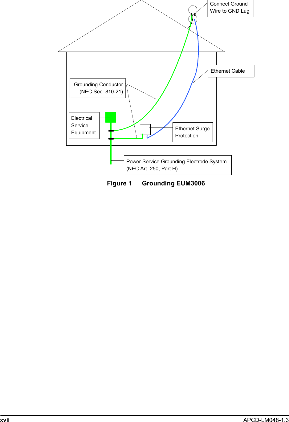


![18 APCD-LM048-1.33: Setup Menu3.4 Troubleshooting Information DisplayThe troubleshooting information is provided to allow the network operator to troubleshoot the link. It is also useful to record the status of the link once the modem is installed and aligned. This can form a reference baseline so that the network operator can judge if the link in future is better or worse than it was when the modem was installed.The information provided below is a brief description of the statistics provided. A detailed understanding of this information is not required to install the EUM3006. If there are problems with the installation, then the installer may contact the network operator and report the information on this display so that the network operator can troubleshoot the installation.The troubleshooting information display is shown below.Troubleshooting information Display WaveRider Communications Inc. Diagnostic Information----------------- MAC Summary ---------------------------------Transmitted Payloads 1Ok : 1105 99.8% 2Ok : 2 0.1% 3Ok : 0 0.0% 4Ok : 0 0.0% Fail Retry : 0 0.0% Fail Timeout : 0Received Packets HCRC Error : 0 0.0% Directed : 5302 95.1% Broadcast : 287 5.1% No Match : 0 0.0%Received Packets with Payloads FCS Error from Peer : 0 0.0%FCS Error to Station : 0 0.0% ICV/MIC Error : 0 0.0% Duplicate : 0 0.0% Too Busy - Discard : 0 0.0% Delivered : 1617 100.2%-------------------- IP Summary --------------------DHCP Enabled : YESIP Address: 192.168.10.250 / 24IP Subnet : 192.168.10.0 ( 255.255.255.0 )Gateway IP Address: 192.168.10.1------------------- Radio Summary ------------------RF Power: 26 dBmAuto Mode - Locked on frequency 9114 RSSI[dBm] RX; TX; R1; R2; R3; F;Retry%; SQ; RNA; RNBRSSI: -69 1; 0; 0; 0; 0; 0; 0; 8; 31; 29](https://usermanual.wiki/Vecima-Networks/E3K6/User-Guide-656796-Page-37.png)

![36 APCD-LM048-1.34: InstallationPing Internet by NameUse the following test to verify that the DNS server IP address is correctly configured in the end-user’s PC and is operating properly:C:\> ping www.google.comPinging www.google.akadns.net [216.239.39.104] with 32 bytes of data:Reply from 216.239.39.104: bytes=32 time=72ms TTL=241Reply from 216.239.39.104: bytes=32 time=69ms TTL=241Reply from 216.239.39.104: bytes=32 time=76ms TTL=241Reply from 216.239.39.104: bytes=32 time=68ms TTL=241Ping statistics for 216.239.39.104: Packets: Sent = 4, Received = 4, Lost = 0 (0% loss),Approximate round trip times in milli-seconds: Minimum = 68ms, Maximum = 76ms, Average = 71ms4.4 Post-InstallationOnce a good link between the CCU and the EUM3006 has been established, the configuration can be completed automatically using the Automatic Remote Configuration feature with a RADIUS Server and database in which the EUM3006 information has been entered. The network operator must update the RADIUS database for the new modem. The configurable items that can be included in the Automatic Remote Configuration include:• password, • all SNMP parameters, • RF Frequency (including enabling Auto CCU Discovery)• number of customers.If the Automatic Remote Configuration feature is not used, then the network operator can connect to the EUM3006 over the air and complete the configuration.Details on configuring a RADIUS Server or manually configuring an individual EUMs are covered in the LMS4000 Managing the Network manual or other manuals, available on the WaveRider web-site.](https://usermanual.wiki/Vecima-Networks/E3K6/User-Guide-656796-Page-55.png)