Vecima Networks E3K6 Outdoor Modem User Manual EUM3006 Installation Guide
Vecima Networks Inc. Outdoor Modem EUM3006 Installation Guide
User Manual

EUM3006 Integrated
Outdoor Modem
Installation Guide
APCD-LM048-1.3

:
APCD-LM048-1.3 ii
Copyright
© 2006 by WaveRider Communications Inc. You may
copy and/or print as many copies of this manual as
you wish, as long as the software license agreement
and this copyright statement are included.
Release 1.3, May 2006
The following are trademarks or registered trademarks of their respective companies or organi-
zations:
Windows XP/Microsoft
Windows 2000/Microsoft

iii APCD-LM048-1.3
Software License Agreement
This is a legal agreement between you (either an individual or an entity) and WaveRider Communica-
tions Inc. for the use of WaveRider computer software, hereinafter the “LICENSED SOFTWARE”.
By using the LICENSED SOFTWARE installed in this product, you acknowledge that you have
read this license agreement, understand it, and agree to be bound by its terms. You further
agree that it is the full and complete agreement between you and WaveRider Communications
Inc., superseding all prior written or verbal agreements of any kind related to the LICENSED
SOFTWARE. If you do not understand or do not agree to the terms of this agreement, you will
cease using the LICENSED SOFTWARE immediately.
1. GRANT OF LICENSE—This License Agreement permits you to use one copy of the LICENSED
SOFTWARE.
2. COPYRIGHT—The LICENSED SOFTWARE is owned by WaveRider Communications Inc. and is
protected by copyright laws and international treaty provisions; therefore, you must treat the
LICENSED SOFTWARE like any other copyrighted material (e.g., a book or magazine).
3. LIMITS OF FEATURE AVAILABILITY—The LICENSED SOFTWARE is sold with limitations as
to certain feature availability and use. These limits are governed by the terms of the purchase
agreement. Any actions resulting in the exceeding of these limits is not permitted, and can result
in unpredictable performance.
4. OTHER RESTRICTIONS—You may not rent or lease the LICENSED SOFTWARE. You
may not reverse engineer, decompile, or disassemble the LICENSED SOFTWARE.
5. LIMITED WARRANTY—The LICENSED SOFTWARE is provided “as is” without any warranty of
any kind, either expressed or implied, including, but not limited to, the implied warranties of
merchantability and fitness for a particular purpose. The entire risk as to the quality and
performance of the LICENSED SOFTWARE is with you, the licensee. If the LICENSED
SOFTWARE is defective, you assume the risk and liability for the entire cost of all necessary
repair, service, or correction.
Some states/jurisdictions do not allow the exclusion of implied warranties, so the
above exclusion may not apply to you. This warranty gives you specific legal
rights, and you may have other rights, which vary from state/jurisdiction to state/
jurisdiction.
WaveRider Communications Inc. does not warrant that the functions contained in
the LICENSED SOFTWARE will meet your requirements, or that the operation of
the LICENSED SOFTWARE will be error-free or uninterrupted.
6. NO OTHER WARRANTIES—To the maximum extent permitted by applicable law, WaveRider
Communications Inc. disclaims all other warranties, either express or implied, including, but not
limited to, the implied warranties of merchantability and fitness for a particular purpose, with
regard to the LICENSED SOFTWARE and the accompanying written materials.
7. NO LIABILITY FOR CONSEQUENTIAL DAMAGES—To the maximum extent permitted by
applicable law, in no event shall WaveRider Communications Inc. or its suppliers be liable
for any damages whatsoever (including, without limitation, damages for loss of business
profits, business interruption, loss of business information, or any other pecuniary loss)
arising from the use of or inability to use the LICENSED SOFTWARE, even if WaveRider
Communications Inc. has been advised of the possibility of such damages, or for any claim
by any other party.
Because some states/jurisdictions do not allow the exclusion or limitation of liability for
consequential or incidental damages, the above limitation may not apply to you. In no event will
WaveRider’s liability exceed the amount paid for the LICENSED SOFTWARE.

:
APCD-LM048-1.3 iv
Warranty
In the following warranty text, “WaveRider®” shall mean WaveRider Communications Inc.
This WaveRider product is warranted against defects in material and workmanship for a period
of one (1) year from the date of purchase. During this warranty period WaveRider will, at its
option, either repair or replace products that prove to be defective.
For warranty service or repair, the product must be returned to a service facility designated by
WaveRider. Authorization to return products must be obtained prior to shipment. The WaveR-
ider RMA number must be on the shipping documentation so that the service facility will accept
the product. The buyer shall pay all shipping charges to WaveRider and WaveRider shall pay
shipping charges to return the product to the buyer within Canada or the USA. For all other
countries, the buyer shall pay shipping charges as well as duties and taxes incurred in shipping
products to or from WaveRider.
WaveRider warrants that the firmware designed by it for use with the unit will execute its pro-
gramming instructions when properly installed on the unit. WaveRider does not warrant that the
operation of the unit or firmware will be uninterrupted or error-free.
Limitation of Warranty
The foregoing warranty shall not apply to defects resulting from improper or inadequate mainte-
nance by the buyer, buyer-supplied interfacing, unauthorized modification or misuse, operation
outside the environmental specifications for the product, or improper site preparation or mainte-
nance. No other warranty is expressed or implied. WaveRider specifically disclaims the implied
warranties of merchantability and fitness for any particular purpose.
No Liability for Consequential Damages
To the maximum extent permitted by applicable law, in no event shall WaveRider or its suppliers
be liable for any damages whatsoever (including, without limitation, damages for loss of busi-
ness profits, business interruption, loss of business information, or any other pecuniary loss)
arising from the use of or inability to use the product, even if WaveRider has been advised of the
possibility of such damages, or for any claim by any other party.
Because some states/jurisdictions do not allow the exclusion or limitation of liability for conse-
quential or incidental damages, the above limitation may not apply to you.
In no event will WaveRider’s liability exceed the amount paid for the product.
Regulatory Notices
This equipment has been tested and found to comply with the limits for a Class B Intentional
Radiator, pursuant to Part 15 of the FCC Regulations. These limits are intended to provide pro-
tection against harmful interference when the equipment is operated in a residential environ-
ment.
This equipment generates, uses, and can radiate radio frequency energy and, if not installed
and used in accordance with the instruction manual, may cause harmful interference to radio
communications. However, there is no guarantee that interference will not occur in a particular
installation.
Notice to User
Any changes or modifications to equipment that are not expressly approved by WaveRider may
void the user’s authority to operate the equipment.

vAPCD-LM048-1.3

:
APCD-LM048-1.3 vi
Contents
Figures . . . . . . . . . . . . . . . . . . . . . . . . . . . . . . . . . . . . . . . . . . . . . . . . . . . . . . . . . . . . . . . . .viii
Tables . . . . . . . . . . . . . . . . . . . . . . . . . . . . . . . . . . . . . . . . . . . . . . . . . . . . . . . . . . . . . . . . . . . x
Preface . . . . . . . . . . . . . . . . . . . . . . . . . . . . . . . . . . . . . . . . . . . . . . . . . . . . . . . . . . . . . . . . . xii
1 Introduction . . . . . . . . . . . . . . . . . . . . . . . . . . . . . . . . . . . . . . . . . . . . . . . . 1
1.1 Document Scope . . . . . . . . . . . . . . . . . . . . . . . . . . . . . . . . . . . . . . . . . . . . . . . . . . . . . 1
1.2 EUM3006 Features. . . . . . . . . . . . . . . . . . . . . . . . . . . . . . . . . . . . . . . . . . . . . . . . . . . . 2
1.3 EUM3006 - End-user Modem or Customer Premises Equipment . . . . . . . . . . . . . . . . 5
1.3.1 Key Components . . . . . . . . . . . . . . . . . . . . . . . . . . . . . . . . . . . . . . . . . . . . . . . . 5
1.3.2 EUM3006 Integrated, High Gain, Active Diversity Antenna . . . . . . . . . . . . . . . 5
1.3.3 Ethernet Port . . . . . . . . . . . . . . . . . . . . . . . . . . . . . . . . . . . . . . . . . . . . . . . . . . . 6
1.3.4 Power over Ethernet (PoE) Injector . . . . . . . . . . . . . . . . . . . . . . . . . . . . . . . . . 7
1.3.5 PoE Lightning Arrestor . . . . . . . . . . . . . . . . . . . . . . . . . . . . . . . . . . . . . . . . . . . 7
1.4 Installation Aids. . . . . . . . . . . . . . . . . . . . . . . . . . . . . . . . . . . . . . . . . . . . . . . . . . . . . . . 8
2 MDB1000 . . . . . . . . . . . . . . . . . . . . . . . . . . . . . . . . . . . . . . . . . . . . . . . . . . . 9
2.1 Placing the MDB1000 . . . . . . . . . . . . . . . . . . . . . . . . . . . . . . . . . . . . . . . . . . . . . . . . . . 9
2.2 Powering the MDB1000 . . . . . . . . . . . . . . . . . . . . . . . . . . . . . . . . . . . . . . . . . . . . . . . . 9
2.3 Turning the MDB1000 On . . . . . . . . . . . . . . . . . . . . . . . . . . . . . . . . . . . . . . . . . . . . . . 10
2.4 Turning the MDB1000 Off . . . . . . . . . . . . . . . . . . . . . . . . . . . . . . . . . . . . . . . . . . . . . . 11
2.5 Interpreting the LEDs . . . . . . . . . . . . . . . . . . . . . . . . . . . . . . . . . . . . . . . . . . . . . . . . . 11
3 Setup Menu . . . . . . . . . . . . . . . . . . . . . . . . . . . . . . . . . . . . . . . . . . . . . . . 15
3.1 Accessing the Setup Menu . . . . . . . . . . . . . . . . . . . . . . . . . . . . . . . . . . . . . . . . . . . . . 15
3.2 Setup Menu. . . . . . . . . . . . . . . . . . . . . . . . . . . . . . . . . . . . . . . . . . . . . . . . . . . . . . . . . 16
3.3 Radio Link Status Display . . . . . . . . . . . . . . . . . . . . . . . . . . . . . . . . . . . . . . . . . . . . . . 16
3.4 Troubleshooting Information Display . . . . . . . . . . . . . . . . . . . . . . . . . . . . . . . . . . . . . 18
4 Installation . . . . . . . . . . . . . . . . . . . . . . . . . . . . . . . . . . . . . . . . . . . . . . . . 21
4.1 Installation Checklist . . . . . . . . . . . . . . . . . . . . . . . . . . . . . . . . . . . . . . . . . . . . . . . . . . 21
4.2 Pre-Installation Steps . . . . . . . . . . . . . . . . . . . . . . . . . . . . . . . . . . . . . . . . . . . . . . . . . 23
4.2.1 Network and EUM3006 Configuration . . . . . . . . . . . . . . . . . . . . . . . . . . . . . . . 23
4.2.2 Installer’s Kit and Information . . . . . . . . . . . . . . . . . . . . . . . . . . . . . . . . . . . . . 23
4.2.3 Verifying the EUM3006 Components . . . . . . . . . . . . . . . . . . . . . . . . . . . . . . . 24
4.2.4 End-Users PC . . . . . . . . . . . . . . . . . . . . . . . . . . . . . . . . . . . . . . . . . . . . . . . . . 24
4.3 Installation Steps. . . . . . . . . . . . . . . . . . . . . . . . . . . . . . . . . . . . . . . . . . . . . . . . . . . . . 25
4.3.1 Locating the EUM3006 . . . . . . . . . . . . . . . . . . . . . . . . . . . . . . . . . . . . . . . . . . 25
4.3.2 Mounting the EUM3006 . . . . . . . . . . . . . . . . . . . . . . . . . . . . . . . . . . . . . . . . . 26
4.3.3 Running Cables . . . . . . . . . . . . . . . . . . . . . . . . . . . . . . . . . . . . . . . . . . . . . . . . 29
4.3.4 Provide Power to the EUM3006 . . . . . . . . . . . . . . . . . . . . . . . . . . . . . . . . . . . 30
4.3.5 Connecting the End-User’s PC . . . . . . . . . . . . . . . . . . . . . . . . . . . . . . . . . . . . 31
4.3.6 Testing the Data Link . . . . . . . . . . . . . . . . . . . . . . . . . . . . . . . . . . . . . . . . . . . 32
4.4 Post-Installation . . . . . . . . . . . . . . . . . . . . . . . . . . . . . . . . . . . . . . . . . . . . . . . . . . . . . 36

vii APCD-LM048-1.3
Appendix A Factory Configuration . . . . . . . . . . . . . . . . . . . . . . . . . . . . . . . . . . . . . . . . 37
Appendix B Ethernet Cables and Connectors . . . . . . . . . . . . . . . . . . . . . . . . . . . . . . . 39
Index . . . . . . . . . . . . . . . . . . . . . . . . . . . . . . . . . . . . . . . . . . . . . . . . . . . . . . . . . . . . . . . . . . . 43

:
APCD-LM048-1.3 viii
Figures
Figure 1 Grounding EUM3006 . . . . . . . . . . . . . . . . . . . . . . . . . . . . . . . . . . . . . . . . .xvii
Figure 1 EUM3006 Integrated Outdoor Modem . . . . . . . . . . . . . . . . . . . . . . . . . . . . . 3
Figure 2 EUM3006 Longitudinal and Transverse Axes . . . . . . . . . . . . . . . . . . . . . . . . 6
Figure 3 PoE Injector . . . . . . . . . . . . . . . . . . . . . . . . . . . . . . . . . . . . . . . . . . . . . . . . . . 7
Figure 4 MDB1000 . . . . . . . . . . . . . . . . . . . . . . . . . . . . . . . . . . . . . . . . . . . . . . . . . . 10
Figure 5 EUM3006 Mounting - Vertical Orientation . . . . . . . . . . . . . . . . . . . . . . . . . . 28
Figure 6 EUM3006 Mounting - Horizontal Orientation . . . . . . . . . . . . . . . . . . . . . . . 29
Figure 7 PoE Injector - Data & PWR and Data Ports . . . . . . . . . . . . . . . . . . . . . . . . 30
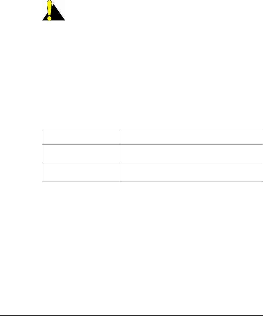
Figure 8 T568A Wiring . . . . . . . . . . . . . . . . . . . . . . . . . . . . . . . . . . . . . . . . . . . . . . . 41
Figure 9 T568B Wiring . . . . . . . . . . . . . . . . . . . . . . . . . . . . . . . . . . . . . . . . . . . . . . . 41

ix APCD-LM048-1.3

:
APCD-LM048-1.3 x
Tables
Table 1 MDB1000 Signal Strength FOMs . . . . . . . . . . . . . . . . . . . . . . . . . . . . . . . . 12
Table 2 MDB1000 Signal Quality LEDs . . . . . . . . . . . . . . . . . . . . . . . . . . . . . . . . . . 13
Table 3 Pre-Installation Stage Checklist . . . . . . . . . . . . . . . . . . . . . . . . . . . . . . . . . 21
Table 4 Installation Stage Checklist . . . . . . . . . . . . . . . . . . . . . . . . . . . . . . . . . . . . . 22
Table 5 Ethernet Interface Card LED Status Displays . . . . . . . . . . . . . . . . . . . . . . . 31
Table 6 Ethernet Interface Specifications . . . . . . . . . . . . . . . . . . . . . . . . . . . . . . . . 40
Table 7 Wiring T568A and T568B ends for Ethernet Cables . . . . . . . . . . . . . . . . . . 40

xi APCD-LM048-1.3
:
APCD-LM048-1.3 xii
Preface
Conventions
The following conventions are used throughout this document:
WARNING!
Whenever you see this icon and heading, the associated text
addresses or discusses a critical safety or regulatory issue.
CAUTION: Whenever you see this icon and heading, the
associated text discusses an issue, which, if not followed, could
result in damage to, or improper use of, the equipment or
software.
TIP: Whenever you see this icon and heading, the associated
text provides a tip for facilitating the installation, testing, or
operation of the equipment or software.
Regulatory Notices
This device has been designed to operate with its integrated antenna only. This device has
been tested using unshielded Ethernet CAT-5E cable.
Industry Canada
Operators must be familiar with IC RSS-210 and RSS-102. The EUM3006 has been
designed and manufactured to comply with IC RSS-210 and RSS-102.
Federal Communications Commission
The EUM3006 has been designed and manufactured to comply with FCC Part 15.
Operators must be familiar with the requirements of the FCC Part 15 Regulations prior
to operating any link using this equipment. For installations outside the United States,
contact local authorities for applicable regulations.
The transmitter of this device complies with Part 15.247 of the FCC Rules.

xiii APCD-LM048-1.3
Note: This equipment has been tested and found to comply with the limits for a Class
B digital device, pursuant to part 15 of the FCC Rules. These limits are designed to
provide reasonable protection against harmful interference in a residential installation.
This equipment generates, uses and can radiate radio frequency energy and, if not
installed and used in accordance with the instructions, may cause harmful
interference to radio communications. However, there is no guarantee that
interference will not occur in a particular installation. If this equipment does cause
harmful interference to radio or television reception, which can be determined by
turning the equipment off and on, the user is encouraged to try to correct the
interference by one or more of the following measures:
• --Reorient or relocate the receiving antenna.
• --Increase the separation between the equipment and receiver.
• --Connect the equipment into an outlet on a circuit different from that to which the
receiver is connected.
• --Consult the dealer or an experienced radio/TV technician for help.
Interference Environment
Operation is subject to the following conditions:
• This device may not cause harmful interference and,
• This device must accept any interference received, including interference that
might cause undesired operation.
Operational Requirements
In accordance with the FCC Part 15 regulations:
1. The maximum average power output of the intentional radiator shall not
exceed one (1) watt (30 dBm) for all spread spectrum systems operating in
the 902 to 928MHz band.
2. Stations operating in the 902 to 928MHz band may use transmitting antennas
of directional gain greater than 6dBi, provided the average output power from
the intentional radiator is reduced by the amount in dB that the directional gain
of the antenna exceeds 6dBi.
3. The operator of a spread spectrum system and the user of the radio device
are each responsible for ensuring that the system is operated in the manner
outlined in Interference Environment on page xiii.
The EUM3006 with its integrated antenna complies with these requirements.
:
APCD-LM048-1.3 xiv
Warnings and Advisories
General Advisory
Installers, operators and maintenance personnel must be familiar with the related safety
requirements before they attempt to install or operate the EUM3006.
It is the responsibility of the operator to ensure that the public is not exposed to excessive
Radio Frequency (RF) levels. The applicable regulations can be obtained from local
authorities.
WARNING!
The EUM3006 Integrated Outdoor Modem must be properly
grounded. WaveRider assumes no liability for failure to
adhere to this recommendation or to recognized general
safety precautions.
WARNING!
To comply with FCC RF exposure limits, the EUM3006 must
be fix-mounted outdoors to provide a separation distance of
30cm (1 foot) or more from all persons to satisfy RF exposure
requirements. The distance is measured from the nearest
point of the modem to the human body. It is recommended
that the modem be installed in a location with minimal
pathway disruption by nearby personnel.
Important Safeguards
WARNING!
CAUTION: Do not open the EUM3006, since there are no user-
serviceable parts inside and opening the EUM3006 will void
its warranty. Refer servicing to qualified personnel.
1. Read all these instructions before installing and operating the EUM3006.
2. Retain these instructions for future reference.
3. Heed all warnings on the EUM3006 and in these instructions.
4. Follow all instructions.
5. Do not use EUM3006 and PoE Injector near water.
6. Unplug EUM3006 and PoE Injector from the wall outlet before cleaning. Clean only
with a damp cloth.

xv APCD-LM048-1.3
7. Use only attachments recommended by WaveRider.
8. The fins and metal casing protect the EUM3006 from overheating to ensure reliable
operations. Do not cover the EUM3006 and PoE Injector. Do not place the EUM3006
or PoE Injector near or over a radiator, stove, heat register or other source of heat. Do
not place the EUM3006 and PoE Injector in a built-in installation such as a bookcase
or rack unless proper ventilation is provided. The EUM3006 has an outdoor
temperature rating, so it can handle a much larger range of temperatures than the
PoE injector. However, it is still possible to exceed the EUM3006 specifications by
improper placement or ventilation.
9. Operate the EUM3006 only from a 48 VDC PoE Mode B power source.
10. Operate the PoE Injector only from a 100 - 250 VAC, single phase, 47-63 Hz AC
power source. The PoE Injector is rated for indoor use only.
11. The PoE Injector is equipped with a 3-wire grounding-type plug, which will only fit into
a grounding-type power outlet. This is a safety feature. If you are unable to insert the
plug into the outlet, contact an electrician to replace your obsolete outlet. Do not
defeat the purpose of the grounding-type plug.
12. Route the AC Power-supply cord and Ethernet cables so that they are not likely to be
walked on or pinched by items placed upon or against them, paying particular
attention to cord and cables at their plugs, convenience receptacles and the points
where the cords exit the equipment.
13. Provide strain relief for cables near their connections. This is typically done by leaving
a loop in the cable near the connection.
14. Ensure the system is properly grounded to provide some protection against voltage
surges and built-up static charges.
15. Do not locate the EUM3006 in the vicinity of overhead power lines or other electric
light or power circuits, or where it can fall onto such power lines or circuits. When
installing outdoors, take extreme care to keep from touching such power lines or
circuits, as contact with them might be fatal.
16. For added protection during a lightning storm, or when it is left unattended and unused
for long periods of time, unplug the Ethernet cable from the PoE injector to the
EUM3006 and unplug the PoE Injector from the wall outlet. If the Ethernet cable to the
EUM3006 goes through a PoE Lightning Arrestor, then disconnect the inside Ethernet
cable. This will power down the EUM3006.
17. Do not overload wall outlets and extension cords as this increases the risk of fire or
electric shock.
18. Never push objects of any kind through openings in this wireless product as they may
touch dangerous voltage points or short-out parts that could result in a fire or electric
shock. Never spill liquid of any kind on the PoE Injector. The EUM3006 is an outdoor
unit, but it is not submersible nor is it immune to all liquids.
19. Do not attempt to service this wireless product yourself, as opening or removing
covers may expose you to dangerous voltage or other hazards. Refer all servicing to
qualified service personnel.

:
APCD-LM048-1.3 xvi
20. Unplug PoE Injector from the wall outlet and refer servicing to qualified service
personnel under the following conditions:
• When the power supply cord or plug is damaged.
• If liquid has been spilled or objects have fallen into these products.
• If the PoE Injector has been exposed to rain or water.
• If the EUM3006 does not operate normally for an extended period of time when
following the operating instructions. Note that it is possible that Internet traffic can
be slow even under normal operations due to network congestion and radio
interference and fading and not as result of problems with the EUM3006.
• When the EUM3006 or PoE Injector exhibit distinct changes in performance. This
may indicate a need for service.
21. When replacement parts are required, be sure the service technician has used
replacement parts specified by the WaveRider or with the same characteristics as the
original part. Improper substitutions may result in fire, electric shock or other hazards.
22. Upon completion of any service or repairs to this wireless product, ask the service
technician to perform safety checks to determine that the wireless product is in proper
operating condition.
23. Follow WaveRider recommendations when mounting the EUM3006 on a wall, roof, or
tower.
24. Install the EUM3006 in compliance with local and national electrical codes. The
following are the national codes. The installer is responsible for knowing the
appropriate local codes.
• In the United States, use the National Electrical Code (NEC);
• In Canada, use the Canadian Electrical Code, Part 1, CSA C22.1;
• In other countries, use International Electrotechnical Commission (IEC) 364,
part 1 through 7.
25. Ensure that the EUM3006 is properly grounded by attaching a grounding cable to the
bolt marked “GND” on the back of the EUM3006. Art. 820-40 of the NEC (US)
provides guidelines for proper grounding and, in particular, specifies that the
grounding cable(s) shall be connected to the grounding system of the building, as
close to the point of cable entry as possible.
xvii APCD-LM048-1.3
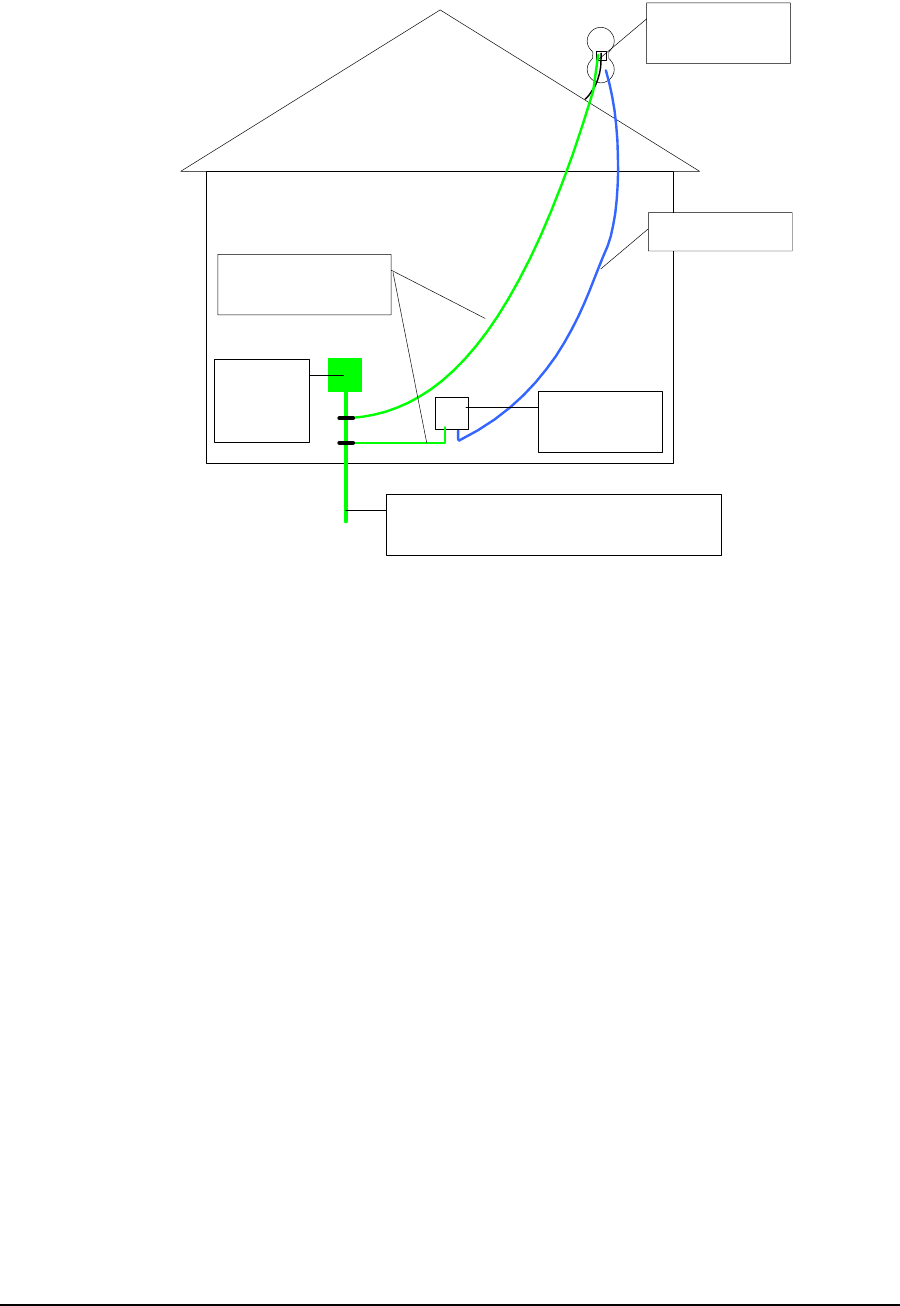
Figure 1 Grounding EUM3006
Connect Ground
Wire to GND Lug
Grounding Conductor
(NEC Sec. 810-21)
Ethernet Cable
Ethernet Surge
Protection
Electrical
Service
Equipment
Power Service Grounding Electrode System
(NEC Art. 250, Part H)

:
APCD-LM048-1.3 xviii
Revision History
Customer Support
An extensive knowledge base is available at support.waverider.com.
WaveRider offers a complete training program. Please contact your sales representative for
training information.
WaveRider also offers priority telephone and email support. Please contact your sales
representative for details.
Date Revision Description
Nov 2004 1.0 Initial Version
Dec. 2004 1.1 Correct Power for FCC
Jan 2005 1.2 Update Power and add Industry Canada
May 2006 1.3 SW Version 11.0 - Security Features

xix APCD-LM048-1.3

APCD-LM048-1.3 1
1 Introduction
The LMS4000 900 MHz Radio Network provides wireless high-speed Internet connectivity to
business, SOHO (small office, home office) and residential customers. LMS4000 operates in a
point-to-multipoint configuration, with one base station efficiently serving many subscriber
stations. LMS4000 transmission is based on a high-performance MAC protocol, and industry-
standard IP routing, Ethernet switching and data encryption technology. No radio license is
required, since LMS4000 operates in the 900 MHz ISM band. LMS4000 can deliver Internet
service over long ranges and often where the radio paths between the base station and
subscribers are partially or even totally obscured, that is, non-line-of-sight. Connection
between the end-user’s computer and the subscriber station is through an Ethernet port.
The EUM3006 Integrated Outdoor Modem is the latest modem for the LMS4000 system and
offers significant improvements: outdoor unit with extended temperature range; integrated,
high-gain, active diversity antenna; 802.3af compatible, 48 VDC Power over Ethernet; higher
output power; improved Rx Sensitivity; DHCP Client; Auto CCU Discovery, Automatic Remote
Configuration; Secure Authentication and User Data Encryption; easy-to-use Setup menu and
MDB1000 alignment tools; VoIP support.
1.1 Document Scope
This Installation Guide covers only the EUM3006 Integrated Outdoor Modem. It provides
information on the installation of the EUM3006, its performance, and any required regulatory
information, including approved installation notices.
Related information can be found in the suite of available LMS4000 manuals, which includes
the following:
•LMS4000 900 MHz Radio Networking Concepts (APCD-LM053)
•LMS4000 Data Networking Concepts (APCD-LM050)
•LMS4000 Managing the Network (APCD-LM052)
•LMS4000 CLI Reference Manual (APCD-LM051)
•LMS4000 SNMP Reference Manual (APCD-LM049)

2APCD-LM048-1.3
1: Introduction
• Acronyms and Glossary (APCD-LM056 )
These manuals provide information not included in this Installation Guide, including
information on:
• Planning, installing and managing the network.
• Diagnostic tools for the network and EUM.
• Details on the Command Line Interface and methods of accessing the EUM.
• Manual configuration of the EUM via the CLI.
• Glossary of network terms.
These manuals, as well as manuals for hardware elements, including EUMs and CCUs, can
be found on WaveRider’s Web site (http://www.waverider.com).
Other documents on the WaveRider web site are useful to assist in installing and operating the
EUM3006. For example, you can find information on which roof and wall mounting brackets
are recommended.
WaveRider recommends that you be familiar with the following sections before proceeding
with the instructions in this guide:
•Software License Agreement on page iii
•Warranty on page iv
•Conventions on page xii
•Warnings and Advisories on page xiv
•Important Safeguards on page xiv
NOTE: The information contained in this manual is subject to change
without notice. The reader should consult the WaveRider web site
for updates.
1.2 EUM3006 Features
The EUM3006 is a major step in the evolution of the LMS4000 900MHz Wireless Internet
Modems offered by WaveRider. It is a Power-over-Ethernet, outdoor unit with integrated, high-
gain, active diversity antenna.
The EUM3006 has new features that provide improved RF performance as well as ease of
installation. The RF performance is enhanced due to the integrated, high-gain, active diversity
antenna, improved transmit power, and improved receive sensitivity.

1: Introduction
APCD-LM048-1.3 3
Figure 1 EUM3006 Integrated Outdoor Modem
Hardware and software improvements make outdoor installation easier than ever, allowing
rapid deployment, single person installation, and even end-user self-installation. These
improvements include Power-over-Ethernet, mounting and alignment tools, and Automatic
Remote Configuration of all parameters using DHCP and RADIUS. The Automatic Remote
Configuration of parameters also allows the network operator to easily manage and
reconfigure the EUM3006 after it is installed, including changing frequency, passwords, and
SNMP parameters.
Key features of the EUM3006 include:
•Easy Outdoor Installation - The EUM3006 is tested to meet ETSI 300-019
environmental standards for outdoor installations, with an extended temperature
range of -40º C to 50º C plus solar loading. The EUM3006 can also work in
uninhabited indoor locations, such as attics, if there is an adequate RF signal. The
advantages of an integrated outdoor unit include:
• More flexible installations.
• Improved range since there are no RF losses from long cable runs.
• Lower installation costs.

4APCD-LM048-1.3
1: Introduction
•Integrated, high-gain, active diversity antenna - There are many advantages to the
EUM3006’s integrated antenna:
• Integrated, so that there are no RF losses due to long cable runs.
• High-gain, so that the EUM3006 can generate the maximum RF signal
allowed by FCC and increase the overall operating range.
• Active diversity, which is done on a packet by packet basis, so that the
EUM3006 performs better in a multi-path fading environment.
• Polarization diversity, so that the installer need not worry about what
polarization the CCU is. Sector polarization can be readily changed at the
base stations, with the EUMs automatically adjusting.
•Power over Ethernet (PoE)- The EUM3006 is powered by standard 48 VDC Power
over Ethernet (802.3af Mode B compatible). Since the antenna is integrated, there is
no need for an RF cable. With PoE, there is no need for a separate power and
Ethernet cable. So the EUM3006 has only one standard, unshielded, flexible CAT-5E
cable, making installation simpler.
•48 VDC PoE - Using 48 VDC power allows the EUM3006 to have up to 100 m of
Ethernet cable to the end-user’s PC, which is the maximum by the Ethernet standard.
The PoE injector can be located anywhere along this 100 m of cable. This provides
great flexibility in placing the EUM3006 to get the best RF signal.
•Improved RX Sensitivity - Each EUM3006 is tested to ensure that its RX Sensitivity
is -89 dBm or better (average received signal).
•DHCP Client enabled (factory default)- The EUM3006 can obtain its IP address,
subnet mask and IP gateway information from a DHCP server, reducing the amount of
configuration needed for installation. This also allows the Network Operator to re-
assign IP addresses to EUMs without having to access the EUM itself.
•Auto CCU Discovery (factory default) - The EUM3006 searches the full RF
frequency range to locate CCUs. It then selects the CCU with the best RF signal that
allows it to register. With this and DCHP Client enabled (factory defaults), the installer
does not need to enter ANY configuration parameters into the EUM3006 in order to
install it.
•Automatic Remote Configuration - The EUM3006 will accept parameters from a
RADIUS server to set other configurable parameters in the modem. These
parameters include: password, all SNMP parameters, RF Frequency (including
enabling Auto CCU Discovery), and number of customers.
•Secure Authentication and User Data Encryption: The EUM3006 can perform
mutual authentication with the CCU using the secure 4-way handshake mechanism of
WPA2. All user data flowing over the air can be encrypted using the industry standard
IEEE802.11 TKIP cypher. Traffic to and from each EUM is encrypted using a key
specific to that EUM, ensuring message integrity and privacy for each user.
• Installation Tools - The EUM3006 has two new tools to make installation and
alignment easy and error-free.
•MDB1000 - This hand-held, battery-powered device displays detailed key
signal quality information to allow the EUM3006 to be located and aligned to
the best RF signal possible by a single installer. The MDB1000 can be in any
position to provide easy viewing.
•SETUP Menu - The EUM3006 supports the local link IP address,
169.254.10.250, on its Ethernet port at all times. Using the local-link address,
the user can use the password “setup” to call up the setup menu that allows

1: Introduction
APCD-LM048-1.3 5
any user to check the RF link quality to help align the EUM3006 and
troubleshoot the link. This avoids needing to know the IP address and
password of the modem.
Detailed specifications for the EUM3006 can be found on the WaveRider website.
1.3 EUM3006 - End-user Modem or Customer Premises
Equipment
The EUM3006 Integrated Outdoor Modem, shown in Figure 1, is a rugged outdoor wireless
modem that connects to the end-user’s computer through an Ethernet connection. It is
installed at the end-user’s premises and provides an interface to the customer’s computer or
local area network on one side and wireless access to the LMS4000 network on the other
The EUM3006, which acts as a network bridge, receives data from the CCU (Communication
Access Point Channel Unit = base station) over the 900 MHz radio link, and then forwards this
data to EUM3006 internal processes or to the end-user’s computer through the Ethernet port.
In the other direction, the EUM3006 forwards data received from the end-user’s computer over
the radio link to the CCU
1.3.1 Key Components
These key components of the customer-premises equipment are described on the following
pages:
•EUM3006 Integrated, High Gain, Active Diversity Antenna on page 5
•Ethernet Port on page 6
•Power over Ethernet (PoE) Injector on page 7
•PoE Lightning Arrestor on page 7
1.3.2 EUM3006 Integrated, High Gain, Active Diversity Antenna
The EUM3006 has its antenna integrated with the modem in one package, designed for the
rugged outdoor environment. The EUM3006 antenna is a high gain, active diversity antenna
that ensures that the EUM3006 output power is at the maximum allowed. The active diversity
feature selects the best signal from horizontal and vertical polarizations on a per packet
received basis. Active diversity improves performance in a multi-path fading environment by
selecting the alternate polarization when the other polarization signal fades significantly. This
effectively reduces the depth, frequency and duration of fades when compared to a non-active
or non-diversity antenna system.
Horizontal and vertical polarizations are relative to the earth. Since the EUM3006 can be
mounted in one of two orientations, we use the terms longitudinal axis and transverse axis to
refer to the axes of the modem. See Figure 2.
6APCD-LM048-1.3
1: Introduction
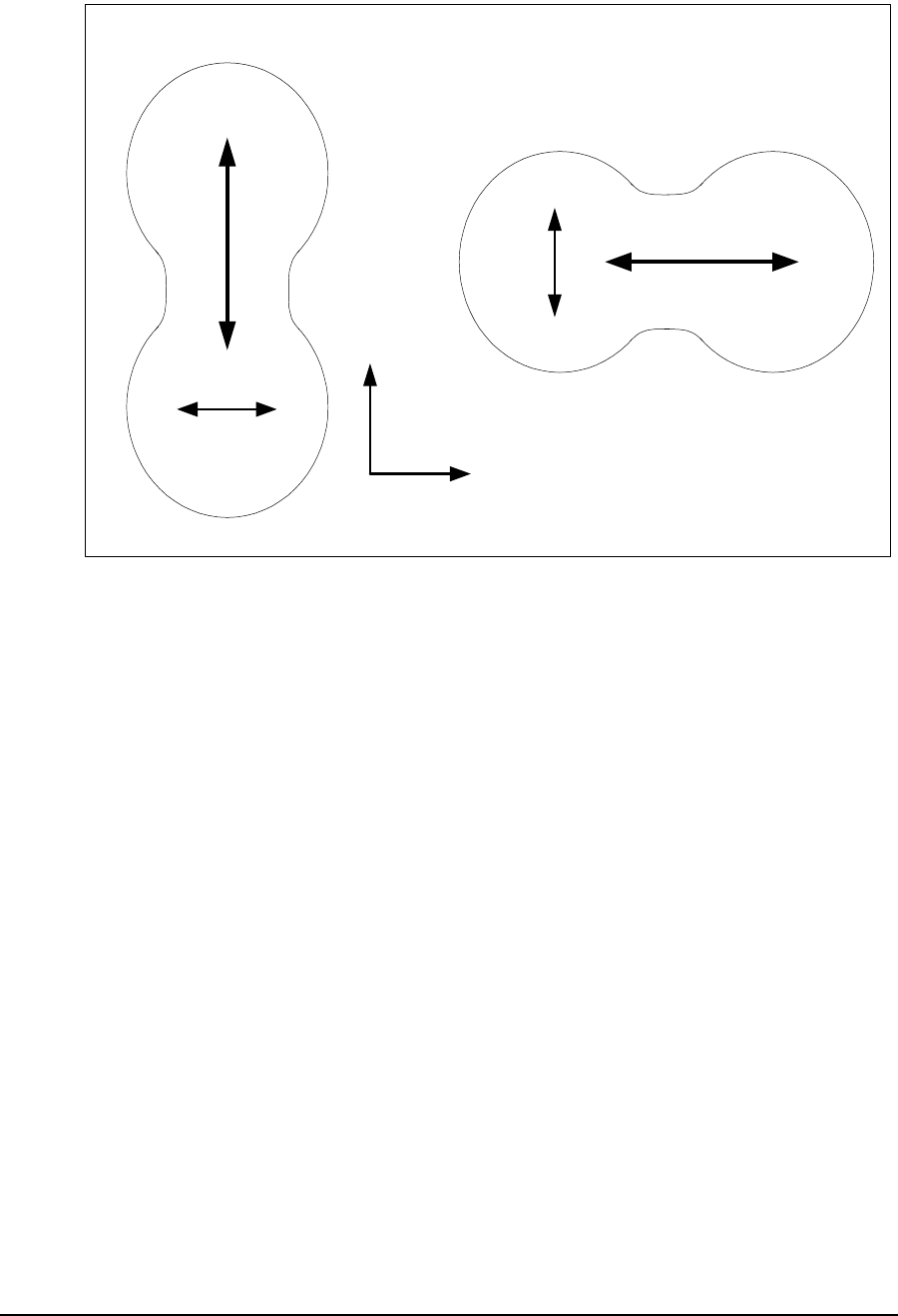
Figure 2 EUM3006 Longitudinal and Transverse Axes
The antenna patterns are longitudinal and transverse polarization. If the modem is mounted
vertically, then the longitudinal polarization coincides with vertical polarization and the
transverse is for horizontal polarization. If the modem in mounted horizontally, then the
longitudinal axis is for horizontal polarization and the transverse is for vertical polarization. See
the installation section for suggestions on mounting orientation.
The EUM3006 samples the signal strength from both antenna polarizations during the
preamble of every received packet and automatically selects the best signal. When the
EUM3006 transmits, it sends on the antenna polarization that was last used to receive a
signal.
The integrated antenna has a front-to-back ratio of more than 15 dB, which helps to suppress
interference.
1.3.3 Ethernet Port
The EUM3006 has a weatherproof 10BaseT Ethernet RJ-45 connector. This makes
installation easy and robust, since the correct length of standard outdoor Ethernet cable can
be connected and made weatherproof with the mating connector provided.
The outdoor Ethernet cable can be plugged into the PoE Injector directly or through extension
cables and a UL-approved PoE Lightning Arrestor (recommended, may be required by local
and national codes). Details on the Ethernet port are found in Appendix B on page 39.
Vertical
Horizontal
Modem Vertically Mounted
Modem Horizontally Mounted
Longitudinal Axis
Transverse
Axis
Longitudinal Axis
Transverse
Axis
1: Introduction
APCD-LM048-1.3 7
There is great latitude available in locating the EUM3006 and routing the Ethernet cable, since
up to 330 feet (100 m) of Ethernet cable can be used between the EUM3006 and the end-
user’s computer, router or Ethernet switch.
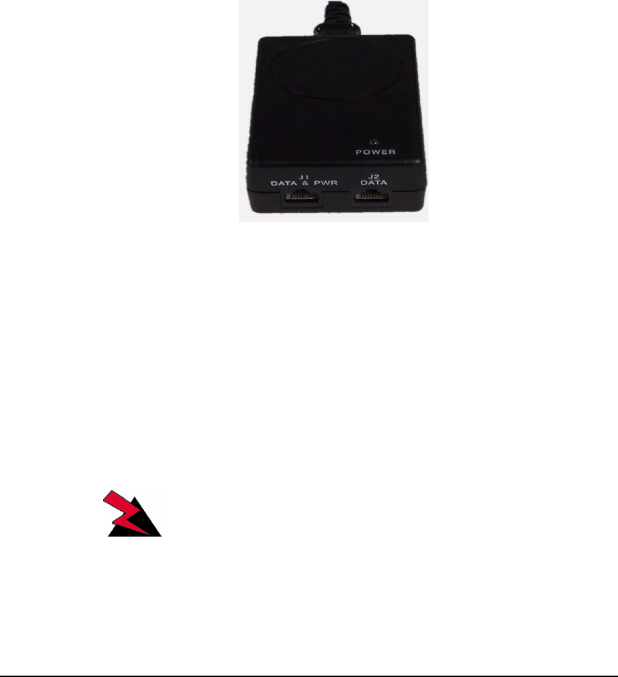
1.3.4 Power over Ethernet (PoE) Injector
Power is provided to EUM3006 Integrated Outdoor Modem through its Ethernet cable. This
power is provided by a device called a PoE Injector, which takes the Ethernet data-only
signals from the cable to the end-user’s computer, switch or router and adds the 48 VDC
power to the Ethernet cable going to the modem. The 48 VDC power is provided by converting
the AC power provided to the injector.
Figure 3 PoE Injector
Using the standard 48 VDC means that the PoE Injector can be located at any point between
the end-user and the EUM3006, without worrying about excessive voltage drop.
The supplied PoE injector is rated for indoor conditions.
The supplied PoE Injector need not be used if 48 VDC 802.3af Mode B PoE power is being
provided by a router or Ethernet switch. It is beyond the scope of this document to discuss
configuring such devices. It is the installer’s responsibility to ensure that such devices are
compatible with the EUM3006.
WARNING!
Plug the EUM3006 directly into routers or Ethernet switches
ONLY if these are providing compatible 48 VDC 802.3af Mode
B PoE power, in lieu of the supplied PoE Injector.
1.3.5 PoE Lightning Arrestor
A PoE lightning arrestor (not supplied) is used with the EUM3006 if it is required by the
national building codes and/or the EUM3006 is being installed in an area subject to direct or

8APCD-LM048-1.3
1: Introduction
indirect lightning induced surges. The lightning arrestor must be able to pass the Ethernet data
lines as well as the Power over Ethernet lines. The lightning arrestor must be grounded in
accordance with local and national electrical codes.
1.4 Installation Aids
The following features make installation much easier and faster:
•MDB1000 on page 9
•Setup Menu on page 15
The chapter on Installation on page 21 gives step-by-step instructions to ensure a successful
installation.

APCD-LM048-1.3 9
2 MDB1000
To make installation an easy one person job, the MDB1000 (Magnetic Decoder Box) is a light,
portable, battery operated device that provides signal performance indicators that assist in
locating and aligning the EUM3006. The MDB1000 picks up a magnetic signal from the
EUM3006 from any position within 4 inches of the EUM3006. This allows the installer to put
the MDB in a convenient position, regardless of the orientation of the EUM3006 or
awkwardness of the mounting location. By indicating 8 levels of signal strength and 5 levels of
signal quality, the MDB1000 allows the installer to find the optimal location and alignment. The
MDB1000 is shown in Figure 4
2.1 Placing the MDB1000
The MDB1000 comes with a belt clip and two velcro straps, a short one to attach the
MDB1000 to your wrist or forearm and a longer one to attach to the EUM3006 itself or the pole
mount. So long as the MDB1000 is within 4 inches of the EUM3006, it picks up the magnetic
signal sent by the EUM3006. If MDB1000 does not indicate it is receiving a signal, move it
closer to the waist of the modem.
The EUM3006 will stop sending the magnetic signal one hour after it has been started. If in
doubt, simply re-power the EUM3006 to ensure that it is transmitting the MDB1000’s signal.
2.2 Powering the MDB1000
The MDB1000 requires two AA batteries. It is recommended that long-life batteries, such as
the Eveready Lithium LN91, be used, which have a long shelf life. Under normal conditions,
these batteries should last for many months. Unlike other batteries, lithium batteries are rated
to -40 C. However, sustained temperatures below -10 C will severely limit the battery lifetime.
10 APCD-LM048-1.3
2: MDB1000
It is recommended that the batteries be tested before starting the installation. Keeping a spare
set of batteries with the installation tools may save you a trip down ladders, etc. to get new
batteries.
The AA batteries fit into the MDB1000 by removing the battery cover at the back of MDB1000,
removing the old batteries, and inserting the new ones. Ensure batteries are inserted with the
correct polarity.
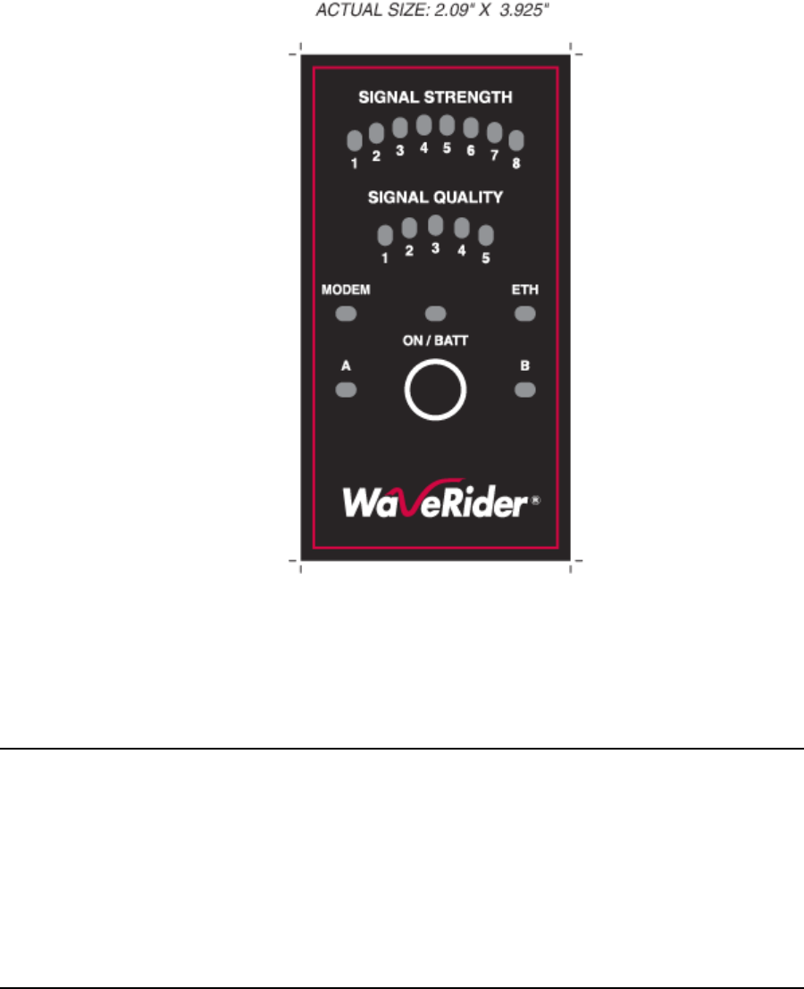
Figure 4 MDB1000
2.3 Turning the MDB1000 On
The MDB1000 is self-tested every time it is turned on. Press the ON button. Each LED should
flash on and off twice a second for 5 seconds before showing the signal performance values. If
this does not happen, then the batteries could be low and should be replaced.
The ON/BATT LED will flash continually when the battery is low and should be replaced.

2: MDB1000
APCD-LM048-1.3 11
2.4 Turning the MDB1000 Off
The MDB1000 automatically shuts off if it is out of range of the EUM3006 for more than 60
seconds. You can tell if the MDB1000 is out of range, since the MODEM LED will go out as
well as all of the signal performance indicator LEDs. Only the ON/BATT LED will remain lit (or
flashing if the battery is low).
Pressing the ON button has no effect once the MDB1000 is on.
2.5 Interpreting the LEDs
There are 6 groups of LEDs:
ON/BATT
This LED has three states:
• ON - MDB1000 is working and batteries are good
• FLASHING - The batteries are low and should be replaced
• OFF - MDB1000 has turned itself off
MODEM
ON when the MDB1000 is receiving good data from the EUM3006. If the LED is OFF, then all
the remaining LEDs are OFF.
ETH
ON when the EUM3006 has an Ethernet link to the end-user PC or router.
SIGNAL STRENGTH
These 8 LEDs show the state of the EUM3006 if the MODEM LED is on. There are three
states shown:
1. No CCU - All the Signal Strength LEDs are OFF, indicating that the EUM3006 has
acquired a CCU but is not receiving any packets.
2. Auto CCU Discovery Mode - There are two LEDs ON in rotating patterns when the
EUM3006 is in Auto CCU Discovery mode and is searching for a CCU.
3. Normal Reception - If only one LED is ON, then the EUM3006 has registered with a
CCU and is receiving packets. The LED that is ON indicates the average received
Signal Strength Figure of Merit (FOM) for packets from the CCU. Ta b le 1 shows the
mapping between signal strength in dBm and the signal strength FOM.

12 APCD-LM048-1.3
2: MDB1000
Table 1 MDB1000 Signal Strength FOMs
SIGNAL QUALITY
These 5 LEDs have two interpretations, depending on the state of the EUM3006 if the
MODEM LED is on.
1. A rotating pattern of LEDs shows that the EUM3006 is in Auto CCU Discovery mode.
2. When a CCU has been found, the Signal Quality LEDs indicate the figure of merit for
a blend of quality indicators, including the carrier phase error and the signal to noise
ratios for each antenna pattern. The FOM is a value between 0 and 5 and is much
more qualitative that the signal strength. Table 2 shows the meanings of each of the
LED values. LED 0 means that there are no LEDs lit.
LED Meaning Received Signal is at least Received Signal is less than
1Extremely poor -92 dBm
2Very Poor -92 dBm -89 dBm
3Poor -89 dBm -86 dBm
4Marginal -86 dBm -83 dBm
5Okay -83 dBm -80 dBm
6Good -80 dBm -77 dBm
7Very Good -77 dBm -74 dBm
8Excellent -74 dBm

2: MDB1000
APCD-LM048-1.3 13
Table 2 MDB1000 Signal Quality LEDs
Getting any Signal Strength reading at all indicates that packets are being received from the
CCU. The higher the signal strength and signal quality indicators, the lower the packet error
rate and the higher the fade margin for the EUM3006. The goal should be a signal strength of
5 or higher and a signal quality of 4 or 5. Regardless of the levels, the EUM3006 should be
aligned so that the indicators are the highest possible for the given site.
A/B
Reserved for future use.
LED Meaning
0Extremely Poor
1Very poor
2Poor
3Adequate
4Good
5Very Good

14 APCD-LM048-1.3
2: MDB1000

APCD-LM048-1.3 15
3 Setup Menu
The EUM3006 is equipped with a simple setup menu through which you can monitor the RF
link quality and view the key parameters of the modem.
3.1 Accessing the Setup Menu
The setup menu is accessed by connecting a Telnet session to the ‘local link’ IP address of the
EUM3006, 169.254.10.250, with password = ‘setup’. The connection must be through the
Ethernet port, not over the air via the RF link.
The computer needs to have an IP address of 169.254.x.y with a 16 bit mask (255.255.0.0),
where x and y can be any value from 0 to 255 except for 10.250, 0.0, or 255.255. It is
recommended that the address 169.254.10.251 be used unless another address is more
convenient. This address will be used throughout.
The following assumes the computer has a Windows 2000 or Windows XP operating system.
Other operating systems can be used provided the computer has an IP address of
169.254.10.251 and can use ‘ping’ and ‘telnet’ programs.
On Windows 2000, XP and similar systems, the IP Address is set using the Control Panel >
Network and Dialup Connection > Local Area Connections > right mouse click to select
Properties > Internet Protocol (TCP/IP) > Properties.
Once the computer’s IP address is set to 169.254.10.251, open a DOS command window and
try to ping the EUM3006, using the command “ping 169.254.10.250”. If the EUM3006 does not
respond, verify the Ethernet cables are connected correctly, that PoE Injector has power and
that the computer has the correct address and net mask.
When the EUM3006 replies to the ping command, establish a telnet session with the
command “telnet 169.254.10.250”.
Once a telnet connection is established, a password is requested. Enter “setup”, which will
enter the setup menu.

16 APCD-LM048-1.3
3: Setup Menu
3.2 Setup Menu
The Setup Menu structure consists of a menu with four selections.
Setup Menu
WaveRider Communications, Inc. EUM3005
Password: *****
WaveRider Communications Inc. Setup Menu
Modem Serial Number : C00017
Station Identifier (EUM ID): 40:00:17
Software Version : 10.0
Search State : Searching for CCU
Menu
====
(R)adio Link Status - Use this for pointing the antenna
(T)roubleshooting information - for network operator
(H)elp
e(X)it
type option and press enter > r
The Setup menu identifies the modem, the software version and search state. In this case, the
modem is configured for Auto CCU Discovery and it is searching to find the best available
CCU.
There are 4 options:
• Radio Link Status - see section 3.3, Radio Link Status Display
• Troubleshooting information - see section 3.4, Troubleshooting Information Display
• Help - this provides an on-line explanation of the options and the information
displayed with each.
• Exit - this terminates the telnet session.
3.3 Radio Link Status Display
The Radio Link Status display is the key setup display for aligning the antenna and verifying
the link, in a manner similar to the MDB1000. The Radio Link Status display shows the search
state of the modem, which is either:

3: Setup Menu
APCD-LM048-1.3 17
•searching for a CCU - A complete sweep of all frequencies takes about 30 seconds.
The display shows which frequencies may be CCUs. A search is started when any of
the following occurs:
• the modem boots up, either due to a hard (power) reset or software reset,
• no CCUs are found during the last frequency sweep, so that the modem
cannot register with any CCU found during the last sweep,
• the modem has received no traffic from the CCU in the last two minutes
•attempting to register with a CCU - When a frequency sweep has been completed,
the modem attempts to register with the CCUs in the order of best signal down to
poorest. The modem may not register with a CCU for a number of reasons, in which
case the modem attempts the next CCU in the frequency list. If the modem cannot
register with any CCU, contact the network operator. The reasons a modem may not
be able to register with a CCU include:
• The modem is not authorized to register at that CCU,
• The signal detected is not a valid CCU.
•registered with a CCU - This state occurs when the modem has a frequency and has
successfully registered with a CCU. At this point, the modem can provide a link to the
Internet through the CCU.
An example of the Radio Link Status display is shown below.
Radio Link Status Display
Searching: found 9070 9086
Searching: found 9070 9086
Searching: found 9070 9086 9114
Searching: found 9070 9086 9114
Searching: found 9070 9086 9114 9142
Searching: found 9070 9086 9114 9142
Searching: found 9070 9086 9114 9142
Searching: found 9070 9086 9114 9142
Registered at 9114
Signal Strength Signal Quality
| Poor | Fair | Good | Poor |Fair | Good
1 2 3 4 5 6 7 8 | 1 2 3 4 5
4.0 *********** 1.5 *******
4.3 ************ 3.5 *****************
5.0 **************** 3.0 **************
4.7 *************** 2.5 ***********
6.7 *********************** 2.0 *********
5.0 *************** 1.5 *******
3.7 ********* 4.0 ********************
6.0 ******************* 3.0 ***************
8.7 ******************************* 3.5 *****************
8.0 ***************************** 4.5 ***********************
The Signal Strength and Signal Quality graphs and values are the same Figures of Merit
discussed in section 2.5, Interpreting the LEDs. The goal for aligning the antenna is the same
as for the MDB1000, namely a Signal Strength of 5 or better and a Signal Quality of 4 or 5, if
possible.

18 APCD-LM048-1.3
3: Setup Menu
3.4 Troubleshooting Information Display
The troubleshooting information is provided to allow the network operator to troubleshoot the
link. It is also useful to record the status of the link once the modem is installed and aligned.
This can form a reference baseline so that the network operator can judge if the link in future is
better or worse than it was when the modem was installed.
The information provided below is a brief description of the statistics provided. A detailed
understanding of this information is not required to install the EUM3006. If there are problems
with the installation, then the installer may contact the network operator and report the
information on this display so that the network operator can troubleshoot the installation.
The troubleshooting information display is shown below.
Troubleshooting information Display
WaveRider Communications Inc. Diagnostic Information
----------------- MAC Summary ---------------------------------
Transmitted Payloads
1Ok : 1105 99.8%
2Ok : 2 0.1%
3Ok : 0 0.0%
4Ok : 0 0.0%
Fail Retry : 0 0.0%
Fail Timeout : 0
Received Packets
HCRC Error : 0 0.0%
Directed : 5302 95.1%
Broadcast : 287 5.1%
No Match : 0 0.0%
Received Packets with Payloads
FCS Error from Peer : 0 0.0%
FCS Error to Station : 0 0.0%
ICV/MIC Error : 0 0.0%
Duplicate : 0 0.0%
Too Busy - Discard : 0 0.0%
Delivered : 1617 100.2%
-------------------- IP Summary --------------------
DHCP Enabled : YES
IP Address: 192.168.10.250 / 24
IP Subnet : 192.168.10.0 ( 255.255.255.0 )
Gateway IP Address: 192.168.10.1
------------------- Radio Summary ------------------
RF Power: 26 dBm
Auto Mode - Locked on frequency 9114
RSSI[dBm] RX; TX; R1; R2; R3; F;Retry%; SQ; RNA; RNB
RSSI: -69 1; 0; 0; 0; 0; 0; 0; 8; 31; 29

3: Setup Menu
APCD-LM048-1.3 19
The MAC Summary shows the breakdown for transmitted and received packets and payloads.
All values are expressed as a count and percentage of total packets or payloads. A payload is
a packet with real data.
• Transmitted Payloads: shows how many payloads were successfully transmitted the
1st time or needed to be sent a 2nd, 3rd or 4th time to get through, as well as how
many packets failed to get through at all. Note that traffic must be sent from the end
user PC in order to generate enough traffic to be meaningful. The rules of thumb are:
• 1OK should be at least 90%, otherwise the link may not be good enough.
• The 1OK packets should be 1000 or more to be a reasonable representation
of the link.
• Received packets: shows the classification of all packets received from the CCU,
whether they contain payloads or not and whether they are directed to this modem or
not. This data is for information only and does not indicate the quality of the link for the
installer.
• Received packets with payloads: shows the disposal of the received packets with
payloads. FCS Error from Peer shows the error rate for all packets from the CCU,
whether directed to this modem or not. An error rate above 5% could indicate a poor
link. The others are for payloads directed to this modem or broadcast to all modems.
Only the delivered payloads are successfully received. The rule of thumb here is that
the delivered payloads should be better than 95%, otherwise the link is suspect.

20 APCD-LM048-1.3
3: Setup Menu

APCD-LM048-1.3 21
4 Installation
4.1 Installation Checklist
A successful installation is divided into pre-installation, installation and post-installation stages,
with each stage outlined in the following checklists.
The Pre-Installation Stage Checklist involves the Network Operator as well as the installer.
Table 3 Pre-Installation Stage Checklist
When everything is ready for the installation stage, then the installer performs the following
steps:
Step Discussion
section 4.2.1, Network and
EUM3006 Configuration
The network must be properly configured by the
Network Operator to accept the new modem.
section 4.2.2, Installer’s Kit
and Information
The installer requires some equipment, tools and
information prior to installing the modem.
section 4.2.3, Verifying the
EUM3006 Components
Ensure that all the needed parts are included.
section 4.2.4, End-Users PC The end-user’s PC requires an Ethernet Network
Interface to accept the data from the EUM3006.

22 APCD-LM048-1.3
4: Installation
Table 4 Installation Stage Checklist
Once the installation is complete and verified, the network operator can complete the Post-
installation Stage, using the Automatic Remote Configuration feature or manually over the air.
This is discussed in section 4.4, Post-Installation
Step Discussion
section 4.3.1, Locating the
EUM3006
Find the best location for mounting the EUM3006, with a
good RF signal and at least 1 foot away from where
people will stand.
section 4.3.2, Mounting the
EUM3006
The EUM3006 mounts to a vertical pole with a diameter
between 1 and 3.0 inches. Once a location with good
signal levels is found, attach pole mounting hardware
such as a standard Satellite TV mount, to the building or
support structure. Attach the EUM3006 to the pole with
the mounting plate and the two gear clamps.
section 4.3.3, Running
Cables
Run the Ethernet cable from the modem to the PoE
Injector and run the grounding conductor to a suitable
grounding location.
section 4.3.4, Provide
Power to the EUM3006
Connect the modem to a power source, usually the PoE
injector provided.
section 4.3.5, Connecting
the End-User’s PC
Connect the modem to the end-user’s PC.
section 4.3.6, Testing the
Data Link
Confirm that the link is functioning correctly.

4: Installation
APCD-LM048-1.3 23
4.2 Pre-Installation Steps
4.2.1 Network and EUM3006 Configuration
There are a number of steps that must be undertaken by the network operator before installing
an EUM3006. For more information, see the LMS4000 Data Networking Concepts, LMS4000
Radio Concepts and LMS4000 Managing the Network manuals on the WaveRider web-site.
1. CCU Authorization: Ensure that the EUM is authorized at one or more CCUs with the
appropriate Grade of Service.
2. Secure Authentication: If secure authentication and user data encryption are
required, a secret authentication key must be configured in the EUM and CCU (or
RADIUS server).
3. IP Addresses: Configure a DHCP server to accept the new EUM3006’s request for
an IP address, if the modem has DHCP enabled (factory default). If not using DHCP,
then the EUM must be manually configured with the following settings:
• IP address
• Subnet mask
• Gateway IP address
4. Frequency Assignment: If the Auto CCU Discovery feature (factory default) is used,
then the EUM will search for the CCU upon power up. This is the recommended
approach. If for some reason this is not acceptable, then the EUM3006 must be
configured with its radio frequency.
The easiest installation uses the EUM3006 factory defaults, so that the modem will get all of its
IP address information from DHCP and its RF Frequency from the Auto CCU Discovery
feature.
4.2.2 Installer’s Kit and Information
The installer needs the following standard items to complete an installation. These items are
not provided with the EUM3006 modem.
• Pole Mounting HW - provides a vertically aligned 1 - 3.0” pole or pipe, securely
attached to building or tower. Typically this is a Satellite TV wall or roof mount.
• Grounding Conductor and clamps- to provide a good ground for the modem, both for
RF performance and safety requirements. The grounding conductor attaches to the
bolt marked ‘GND’ on EUM3006 at one end and to the building’s Power Service
Grounding Electrode System using a clamp at the other end. The grounding
conductor can also be connected to the Pole Mounting Hardware. The grounding
conductor must be at least 12 AWG copper wire, with a lug with a hole for #12 bolt at
one end. The US National Electrical Code (NEC) Article 810-21 provides guidelines
for the grounding conductor.
• Tie wraps - or other means to secure the outdoor Ethernet cable and Grounding
Conductor to the mounting HW and walls, in order to provide drip loops and strain
relief.

24 APCD-LM048-1.3
4: Installation
• PoE Lighting Arrestor - if mounted outdoors and/or required by local or national
electrical codes. The protector must be able to protect all 8 conductors and must be
able to pass the DC power as well as the data.
• Straight-through Outdoor Rated Ethernet cable(s) - needed to connect the EUM3006
to the Lightning Arrestor or PoE Inector or other lengths of Ethernet cable.
• Ethernet cable from PoE Injector - needed to connect to the end-user’s computer or
switch or router. If the end-user’s computer is connected directly to the PoE injector,
then this must be a cross-over Ethernet cable.
• Tools to bolt the mounting plate to the modem using the 9/16” hex head bolts and to
tighten the gear clamps with either a slot screw driver or 3/8” socket or wrench.
Other useful tools include:
• The MDB1000 makes installation and alignment much easier, avoiding the need for a
PC or PDA. This makes installation a one-person operation.
• Extension cord for the PoE injector (or battery operated PoE Injector, if available) -
This allows you to take the PoE injector along with the modem and apply power when
on a roof or up a ladder. Note that PoE Injector is an indoor unit, so do not use in
inclement weather.
• If custom Ethernet cables are made on-site, then an Ethernet connector crimping tool
is required.
• If it is necessary to splice Ethernet cables outdoors, then the splice must be weather-
proofed, so the appropriate tape and/or outdoor junction boxes are needed.
Useful information includes:
• Direction from the installation site to the CCU.
• Expected signal strength for the installation site based on the network operator’s site
survey or signal strength for other installations in the vicinity.
• The IP address of a site that accepts pings as well as the name of a site that accepts
pings, for testing the data link
4.2.3 Verifying the EUM3006 Components
Verify that the EUM3006 kit is complete with:
• EUM3006 modem with integrated antenna
• Attaching plate with 4 bolts and lock washers
• 2 Gear Clamps
• Mating connector for the weatherproof housing around the Ethernet plug and jack
• AC/DC PoE power supply
• AC power cable
4.2.4 End-Users PC
Ensure that the end-user PC is equipped with an Ethernet interface.

4: Installation
APCD-LM048-1.3 25
4.3 Installation Steps
NOTE: Turn off all cordless phones in the customer’s premises, and any
other equipment that uses the 900MHz ISM band. Once the
installation is complete, turn this equipment back on and monitor
for interference or degraded signal quality.
4.3.1 Locating the EUM3006
Based on the site survey by the network operator and experience in the neighborhood, the
installer should have some estimate of the signal levels expected at the end-user’s premises.
This will influence where the EUM3006 can be located. Examples:
• In areas with very strong signal levels, the EUM3006 could be mounted in the attic or
other indoor locations.
• As the signal levels drop, EUM3006 could be located outside, but under the eaves
and/or against building walls.
• If the signal levels are weak, the EUM3006 may need to be located on the roof and
eventually on a pole above the roof that has good line of sight to the CCU.
If you have no idea what signal levels are expected at your site, it is suggested that you climb
to a high point (e.g. on the top of the roof), power up the modem and see what signal level is
available. If it is good (e.g. Signal Strength FOM is 5 or better), then you can try lower
locations. Remember, the higher the signal level, the better the link in general.
The goal for a good installation is to have the Signal Strength FOM in the range of 5-8 and the
Signal Quality FOM to be in the range 4-5. However, there are many good installations with
lower figures of merit. Using the MDB1000 or Setup Menu, the installer should find the location
that provides the best signal figures of merit and then adjust the EUM3006 to maximize the
FOM readings. In most cases, a signal strength of 5 with a signal quality of 4 is a better signal
that a signal strength of 6 and signal quality of 2.
The following are suggested guidelines for determining where to locate the modem:
• Survey the area with the modem to assess the signal levels before installing the pole
mounting hardware
• Signal indicators should be good.
• Avoid being the highest point nearby if possible, since this is more exposed to
lightning. If signal levels are good enough, mounting under the eaves or in an attic are
preferred since these locations provide added protection from lightning, winds, rain,
and snow.
• Locate the EUM3006 at least 1 foot away from occupied areas to avoid any harm from
emissions.

26 APCD-LM048-1.3
4: Installation
4.3.2 Mounting the EUM3006
Pole Mounting Hardware
Once a good location for the modem has been selected, you need to provide a pole or pipe to
which the EUM3006 can be attached. This can be any pole from 1” to 3.0” diameter. If the pole
is vertical, it is easy to rotate (pan) the modem for the final alignment. The longitudinal axis
must be vertical or horizontal only.
The pole can be held by any standard mounting HW such as Satellite TV mounts. See the
WaveRider web site for suggestions regarding pole mounting hardware.
CAUTION: The Pole mounting hardware MUST BE SECURELY
FASTENED to structure (building, tower, etc.) and must be rated
to withstand the same or worse environmental conditions as the
EUM3006.
Orientation of the EUM3006
Before mounting the EUM3006 to the pole, the orientation of the modem must be determined.
The modem should be mounted vertically (i.e. Longitudinal or long axis mounted vertically
(see Figure 5)) unless the location makes vertical mounting difficult.
The advantages of vertically mounting the modem include:
• Easier to point the modem. Being vertically mounted, the pole mount can be closer to
other structures and still allow the modem to be pointed.
• Less exposure to wind and rain, since less cross section presented.
Attaching the EUM3006 to the Pole Mounting Hardware
Thread the Gear Clamps straps through the slots on the mounting plate before bolting it down
on to the EUM3006. There are two set of slots provided, the closer set are 1” apart and the
farther set are 2” apart. For poles up to 2 1/4” diameter, use the closer set. For poles of greater
than 2 1/4” diameter, use the farther set of slots. Do not use slots that are too far apart for the
diameter of the pole, otherwise there will be excessive bending of the mounting plate.
Bolt the mounting plate to EUM3006 using the bolts and lock washers provided, when the
clamps are in place and the orientation has been decided. Attach the grounding conductor to
the bolt for the hole marked “GND”. Tighten the bolts securely to 8-12 foot-pounds of torque.
CAUTION: The Ethernet cable outlet must be at the lower
position for either orientation. There are labels indicating which is
the top of the modem for vertical and horizontal mounting. Failure
to mount the modem with the correct side to the top will severely
reduce the weather protecting ability of the modem.

4: Installation
APCD-LM048-1.3 27
WARNING!
The grounding conductor must be attached to the bolt in the
hole marked “GND”.
TIP: As a safety precaution, before attaching the modem to the
pole, use a couple of tie-wraps to secure the Ethernet cable and/
or Ground conductor to the pole to ‘catch’ the modem before it
hits the roof or ground, should you drop it.
Tighten the gear clamps around the pole enough to hold the modem but allowing it to rotate
horizontally. Make the final alignment adjustment so that the modem points in the direction of
the best signal. Usually, there are a range of angles with similar signal levels with the levels
falling off as the modem moves out of that range. Point the modem to the middle of this range.
TIP: You can also mount just the mounting plate and gear
clamps to the pole and then attach the modem to the mounting
plate. However, you need to have a stable position since you will
be holding the modem while threading the mounting plate bolts to
the modem. Again, use a tie-wrap to hold the Ethernet cable to the pole first,
as a safety precaution.
Tighten the gear clamp securely to a torque of 24-30 inch-pounds (2.0 to 2.5 foot-pounds).
Some distortion of the attachment plate is expected as the gear clamps are tightened.
WARNING!
Both gear clamps must be used and must be tightened
securely with a socket or box wrench to the specified torque.
Ensure that the modem will not rotate around the pole when reasonable force is applied. Avoid
pressing on the radome, push on the cast base instead.
Provide a drip-loop for Ethernet cable and grounding conductor from EUM3006 to pole (see
Figure 5 and Figure 6). This ensures that there is no strain on Ethernet cable as well as
directing any rain drips away from the modem and its cable outlet.

28 APCD-LM048-1.3
4: Installation
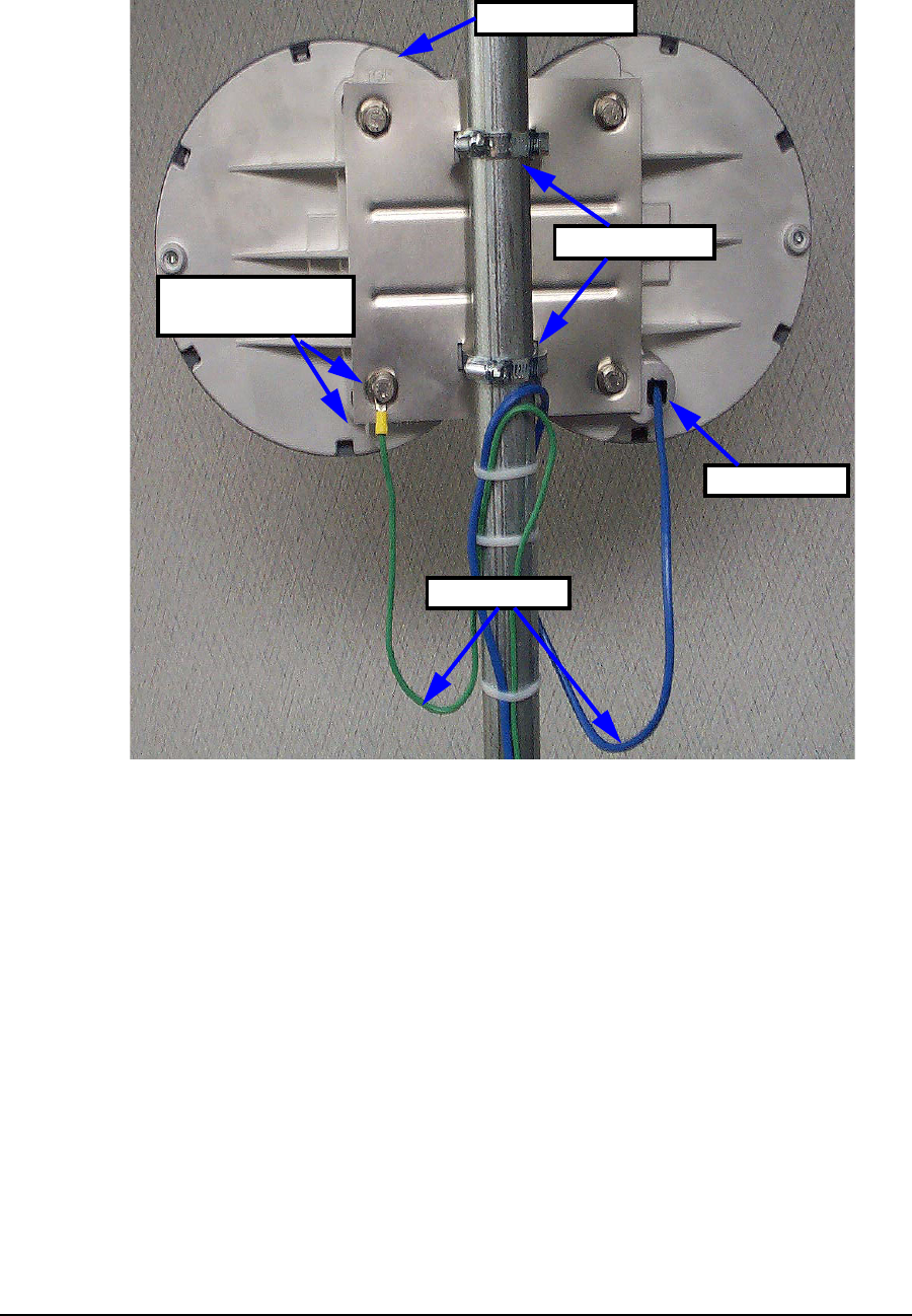
Figure 5 EUM3006 Mounting - Vertical Orientation
Ground Connection
Ethernet Port
Gear Clamps
and GND Marking
TOP Marking
Drip Loops
4: Installation
APCD-LM048-1.3 29
Figure 6 EUM3006 Mounting - Horizontal Orientation
4.3.3 Running Cables
Secure the Ethernet cable and grounding conductor along the pole mounting hardware, the
roof and/or any exterior walls, using standard cable ties or anchors, so that there is little or no
strain on the wires, but they will not flap in the wind. Add lengths of straight-through Ethernet
cables if the provided cable is not long enough. See Appendix B on page 39 for more
information on Ethernet cables.
Attach the grounding conductor to the building’s Power Service Grounding Electrode System
using a ground clamp. See Important Safeguards on page xiv for discussion on good
grounding practices.
If a PoE lightning arrestor is used, it must also be grounded through the building’s Power
Service Grounding Electrode System. The Ethernet cable from the EUM3006 is attached to
the external port of the lightning arrestor and a straight-through Ethernet cable is attached to
the other port.
Ethernet Port
Gear Clamps
Drip Loops
TOP Marking
Ground Connection
and GND Marking
30 APCD-LM048-1.3
4: Installation
The PoE Injector must be located indoors as it is not rated for outdoor conditions. Therefore
the Ethernet cable must enter the building in an appropriate location, preferably near the
lightning arrestor.
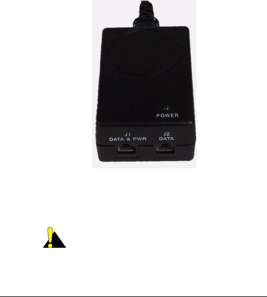
4.3.4 Provide Power to the EUM3006
An indoor PoE Injector, shown in Figure 7, is provided with every EUM3006. Locate it in a
convenient location that has access to an AC plug and the Ethernet cable that runs to the
EUM3006. If a Lightning Arrestor is used, the PoE Injector must be located on the protected
side of the lightning arrestor.
Plug the Ethernet cable to the modem into the port marked “J1 DATA & PWR.
Figure 7 PoE Injector - Data & PWR and Data Ports
Alternatives to the PoE Injector provided can be used, such as PoE enabled routers or
switches. If these provide 48 VDC 802.3af Mode B PoE power, then the EUM3006 can be
connected directly to them.
CAUTION: Failure to use an acceptable PoE power supply may
damage the EUM3006 and void the warranty.
4: Installation
APCD-LM048-1.3 31
4.3.5 Connecting the End-User’s PC
There are many ways to connect the EUM3006 to the end-user’s PC, using Ethernet switches,
IP routers, etc. The discussion below is for the simplest, most direct method of connection,
using the provided PoE Injector.
1. Connect the end-user’s PC by attaching a crossover Ethernet cable (not provided)
between the Ethernet port on the end-user’s computer and the DATA only port on the
PoE Injector (marked “J2 DATA” in Figure 7).
CAUTION: Connecting the End-User PC to the “J1 DATA &
PWR” port on the PoE Injector will provide a DC voltage that could
damage the end-user’s Ethernet interface. Ensure that the end-
user’s equipment in connected to the DATA only port (marked “J2
DATA” in Figure 7) of the PoE Injector and the EUM3006 or its extension
Ethernet cable is connected to the DATA & PWR port (marked “J1 DATA &
PWR”) in Figure 7).
2. Plug the PoE Injector into an AC socket.
3. Check the Ethernet LEDs on the Ethernet interface of the end-user’s PC to ensure the
Ethernet connection between the EUM3006 and the end-user’s PC is active. Refer to
Tab le 5 for an explanation of the Ethernet LEDs normally provided on Ethernet
interface cards.
Table 5 Ethernet Interface Card LED Status Displays
4. When attempting to send data to, or receive data from, the Internet, check the
Ethernet Traffic LED to ensure data transmission is taking place. This LED flashes as
data traffic passes between the end-user’s PC and the EUM3006.
Ethernet LED Status
Ethernet Link LED This LED is lit when there is a correct connection to
the computer, and both ends are powered ON.
Ethernet Traffic LED Flashes when data passes through the Ethernet
connection in either direction.

32 APCD-LM048-1.3
4: Installation
4.3.6 Testing the Data Link
The following are simple tests that the installer or end-user can perform to ensure that the link
is functioning correctly. These tests are outlined below. If any test fails, then the subsequent
tests are likely to fail as well until the problem is resolved.
1. Ping the EUM: Configure the end-user’s PC to have the local link IP address and ping
the EUM3006 at IP address “169.254.10.250” (see Ping the EUM on page 33 for more
details if needed).
2. Assess the Link: Use the Setup Menu as described in Setup Menu on page 15 to
assess the Radio Link Status and to get the Troubleshooting information to baseline
the installation. This test verifies that the end-user’s PC is communicating with the
EUM3006 and provides insight into the state of the RF link. This test is recommended
even if the modem was aligned using the MDB1000, since it provides more details on
the state of the modem and what CCU(s) it has located.
3. Verify DHCP: If the network assigns end-user PC’s IP addresses by DHCP, then
reconfigure the end-user PC to use DHCP to automatically obtain its IP address.
Verify the end-user PC has received an IP address, by using the DOS command
“ipconfig” and seeing that an IP address is assigned along with Gateway and DNS
server addresses This confirms that the End user PC is contacting the DHCP server
correctly.See Verify DHCP on page 34 if more details are required.
4. Ping the Gateway: Assuming the end-user PC has an IP address and a Gateway
address as shown by the “ipconfig” command, ping the gateway to determine if it can
be reached. See Ping the Gateway on page 34 if more details are required.
5. Ping Internet by IP address: If everything is good so far, try pinging a known Internet
address. If successful, then you know that the end-user PC can access the general
Internet. See Ping Internet by IP address on page 35 if more details are required.
6. Ping Internet by Name: Ping a known named Internet address (e.g. “ping
www.google.com” or some equivalent). Even if the site refuses ping commands, you
should get the IP address for the named site. If so, this shows that DNS is working
correctly. See Ping Internet by Name on page 36 if more details are required.
7. Link Speed Test: Go to a known web-site that offers link speed testing, such as “http:/
/bandwidthplace.com/speedtest/”. Follow their instructions and determine the link
speed. There are many factors affecting the link speed between the end-user’s PC
and the test site, including the assigned grade-of-service for the modem, the loading
on the CCU sector and the loading over the rest of the Internet. So this test is not the
best test for ensuring that the modem to CCU link is operating at its correct speed. But
it should indicate that the PC is able to communicate with a site on the Internet.
If any of these tests fail, then the installer may need to check the modem, its alignment, the
cabling, the PC’s configuration and the RF link. If all of these appear good, then the installer
should contact the Network Operator for further troubleshooting advice.
Even if all the above tests indicate a good link, WaveRider recommends that the Network
Operator remotely test the EUM-to-CCU data link more thoroughly soon after it is installed.
The test facilities available to the Network Operator are outlined in the LMS4000 Managing the
Network manual and other manuals on the WaveRider web-site.
The following sections provide more detail for some of the steps for Testing the Data Link.

4: Installation
APCD-LM048-1.3 33
Ping the EUM
Note that the EUM3006 may be on a different sub-net than the end-user’s PC, so pinging the
IP address assigned to the EUM3006 will go through the CCU. Therefore, we ping the
EUM3006 using the local link IP address as the 1st test.
1. Ensure the end-user’s PC is configured with an IP address of 169.254.10.251,
netmask = 16 (or 255.255.0.0). See Setup Menu on page 15 for more information.
2. Ping the EUM’s local-link IP address 169.254.10.250, from the end-user’s PC, as
follows:
• Open a DOS window in the end-user’s PC.
• At the command prompt, type ping 169.254.10.250 and press Enter.
3. If there is no response, check the following:
• The end-user’s computer IP address settings.
• The Ethernet link light on the PC.
• The Ethernet crossover cable between the PoE Injector and the end-user’s
PC, to ensure that the pins have not been damaged.
• The PoE Injector’s POWER LED should be on.
• The Ethernet cables are plugged into the correct ports of the PoE Injector.
• If you have an MDB1000, cycle the power at the PoE Injector to reboot the
EUM3006 and verify that the EUM3006 is communicating with the MDB1000.
Note that the MDB1000 needs to be near the EUM3006. Also, if the EUM3006
has been on for more than 1 hour, it will have stopped sending the magnetic
signal to the MDB1000, hence the reason for cycling the power on the
modem.
4. If there is a response, but with errors, check the Ethernet crossover cable.
This is what a successful ping from the end-user’s PC to the EUM looks like:
C:\>ping 169.254.10.250
Pinging 169.254.10.250 with 32 bytes of data:
Reply from 169.254.10.250: bytes=32 time<10ms TTL=64
Reply from 169.254.10.250: bytes=32 time<10ms TTL=64
Reply from 169.254.10.250: bytes=32 time<10ms TTL=64
Reply from 169.254.10.250: bytes=32 time<10ms TTL=64
Ping statistics for 169.254.10.250:
Packets: Sent = 4, Received = 4, Lost = 0 (0% loss),
Approximate round trip times in milli-seconds:
Minimum = 0ms, Maximum = 0ms, Average = 0ms

34 APCD-LM048-1.3
4: Installation
This is what an unsuccessful ping from the end-user’s PC to the EUM looks like:
C:\>ping 169.254.10.250
Pinging 169.254.10.250 with 32 bytes of data:
Request timed out.
Request timed out.
Request timed out.
Request timed out.
Ping statistics for 169.254.10.250:
Packets: Sent = 4, Received = 0, Lost = 4 (100% loss),
Approximate round trip times in milli-seconds:
Minimum = 0ms, Maximum = 0ms, Average = 0ms
Verify DHCP
This step is for networks that use DHCP to provide IP addresses to the end-user’s computer.
Assuming the Setup command shows that the modem has registered with a CCU and is
receiving a signal, then reconfigure the end-user PC to use the correct IP address. This is
usually done using DHCP to automatically obtain the IP address.
On Windows 2000, XP and similar systems, the IP Address is set using the Control Panel >
Network and Dialup Connection > Local Area Connections > right mouse click to select
Properties > Internet Protocol (TCP/IP) > Properties. To enable DHCP, click on the “Obtain an
IP Address Automatically” button.
Once properly configured, verify the end-user has received an IP address. For a Windows
2000 or XP PC, in a DOS Window, type “ipconfig” and see that there is an IP address
assigned along with a Gateway Address and DNS server addresses This confirms that the
End user PC is contacting the DHCP server correctly. Record the IP Address of the gateway
and the DNS servers.
Ping the Gateway
Ensure the end-user’s PC is configured properly. Then ping the EUM gateway address from a
PC DOS window. The gateway address was recorded during the Verify DHCP address is
using DHCP. Otherwise the installer will know the gateway address since it is needed to
configure the end-user’s PC.
Ping using short packets first (default size) to confirm the connection. Then use long packets
(1472 byte packets) to confirm the RF performance. Errors observed on pings with long
packets indicate a high error rate on the channel, caused by low signal levels or interference.
The following describes how to ping the gateway:
1. Open a DOS window.
2. At the command prompt, type ping <aaa.bbb.ccc.ddd> -t -l 1472, where
<aaa.bbb.ccc.ddd> is the Gateway radio IP address and press Enter.
3. Press Ctrl+c to end the test.

4: Installation
APCD-LM048-1.3 35
NOTE: If this test fails with the long packets, but pinging the Gateway
with the default packet size succeeds, then the connection is
working but is not operating at maximum capacity, possibly due to
poor antenna placement or orientation, poor signal levels, and/or
interference.
The following example assumes the Gateway has an IP address of 172.16.4.1. Replace that
address with the correct gateway address from the ‘ipconfig’ command:
C:\>ping 172.16.4.1 -t -l 1472
Pinging 172.16.4.1 with 1472 bytes of data:
Reply from 172.16.4.1: bytes=1472 time=40ms TTL=64
Reply from 172.16.4.1: bytes=1472 time=81ms TTL=64
Reply from 172.16.4.1: bytes=1472 time=80ms TTL=64
Reply from 172.16.4.1: bytes=1472 time=40ms TTL=64
Reply from 172.16.4.1: bytes=1472 time=60ms TTL=64
Reply from 172.16.4.1: bytes=1472 time=80ms TTL=64
Reply from 172.16.4.1: bytes=1472 time=40ms TTL=64
Reply from 172.16.4.1: bytes=1472 time=110ms TTL=64
Ping statistics for 172.16.4.1:
Packets: Sent = 8, Received = 8, Lost = 0 (0% loss),
Approximate round trip times in milli-seconds:
Minimum = 40ms, Maximum = 110ms, Average = 66ms
Ctrl-C
^C
C:\>
Ping Internet by IP address
Use the following test to determine whether the end-user’s PC can communicate with the
Internet. If you do not know an IP address, try the DNS servers. Otherwise, skip this step.
C:\>ping 216.239.39.104
Pinging 216.239.39.104 with 32 bytes of data:
Reply from 216.239.39.104: bytes=32 time=90ms TTL=113
Reply from 216.239.39.104: bytes=32 time=80ms TTL=113
Reply from 216.239.39.104: bytes=32 time=80ms TTL=113
Reply from 216.239.39.104: bytes=32 time=70ms TTL=113
Ping statistics for 216.239.39.104:
Packets: Sent = 4, Received = 4, Lost = 0 (0% loss),
Approximate round trip times in milli-seconds:
Minimum = 70ms, Maximum = 90ms, Average = 80ms

36 APCD-LM048-1.3
4: Installation
Ping Internet by Name
Use the following test to verify that the DNS server IP address is correctly configured in the
end-user’s PC and is operating properly:
C:\> ping www.google.com
Pinging www.google.akadns.net [216.239.39.104] with 32 bytes of data:
Reply from 216.239.39.104: bytes=32 time=72ms TTL=241
Reply from 216.239.39.104: bytes=32 time=69ms TTL=241
Reply from 216.239.39.104: bytes=32 time=76ms TTL=241
Reply from 216.239.39.104: bytes=32 time=68ms TTL=241
Ping statistics for 216.239.39.104:
Packets: Sent = 4, Received = 4, Lost = 0 (0% loss),
Approximate round trip times in milli-seconds:
Minimum = 68ms, Maximum = 76ms, Average = 71ms
4.4 Post-Installation
Once a good link between the CCU and the EUM3006 has been established, the configuration
can be completed automatically using the Automatic Remote Configuration feature with a
RADIUS Server and database in which the EUM3006 information has been entered. The
network operator must update the RADIUS database for the new modem. The configurable
items that can be included in the Automatic Remote Configuration include:
• password,
• all SNMP parameters,
• RF Frequency (including enabling Auto CCU Discovery)
• number of customers.
If the Automatic Remote Configuration feature is not used, then the network operator can
connect to the EUM3006 over the air and complete the configuration.
Details on configuring a RADIUS Server or manually configuring an individual EUMs are
covered in the LMS4000 Managing the Network manual or other manuals, available on the
WaveRider web-site.

APCD-LM048-1.3 37
Appendix A Factory Configuration
This appendix identifies the factory configuration settings for the EUM3006 Integrated Outdoor
Modem
Parameter Default Configuration
Modem IP Address From DHCP
Modem IP Netmask From DHCP
Gateway IP Address From DHCP
Local Link IP Address
(Available on Ethernet Port only)
169.254.10.250
Local Link IP Netmask 16
255.255.0.0
ffff0000
Maximum Number of Customers* 5
Password* By default, the EUM3006 has no password.
Press Enter at the password prompt to
enter a null password.
Port Filters 137 (both)
138 (both)
139 (both)
445 (both)
1512 (both)
Radio Enabled
Radio Frequency* Auto CCU Discovery

38 APCD-LM048-1.3
Appendix A: Factory Configuration
* These parameters can be set using Automatic Remote Configuration if the network is
configured to use a RADIUS Server.
Radio Power +26 dBm (High) - To be consistent with
previous modems, +26 is used in the CLI to
indicate maximum output power. (NOTE:
For configuring the modem, the power
values entered are rounded to the nearest
dB)
Authentication Key Policy none
SNMP Name* (= Console Prompt) EUMID
SNMP Contact* WaveRider Communications Ltd.
SNMP Location* www.waverider.com
SNMP Read Communities* None entered
SNMP Write Communities* None entered
SNMP Traps* None entered
Statistics Log Interval 15 minutes
Parameter Default Configuration

APCD-LM048-1.3 39
Appendix B Ethernet Cables and
Connectors
There will be several Ethernet cables used in installing the EUM3006:
•EUM3006 Cable: A short Ethernet cable with a weatherproof adapter is attached to
the EUM3006. Straight-through cables connect this to the DATA & PWR port of the
PoE Injector.
•Cross-over Cable: The Ethernet cable from the DATA port of the PoE Injector to the
end-user’s PC must be a cross-over cable. A cross over cable has one end wired
according to T568A and the other end according to T568B. Both ends have RJ45
connectors.
•Straight-Through Cable: Straight-through Ethernet cables have both ends wired
according to T568A with RJ45 connectors. Straight-through cables can be used in a
number of locations:
• If a PoE lightning arrestor is used in the installation, then the cable between
the lightning arrestor and PoE injector must be straight-through.
• Straight-through Ethernet cable is to provide to connect the EUM3006 to the
lightning arrestor.
• If the EUM3006 is to be connected to a router or Ethernet Switch that do not
provide PoE, then a straight-through Ethernet cable is used to connect the
router or switch to the PoE injector.
• If a router or Ethernet switch are used, then they are connected to the end-
user’s PC by a straight-through Ethernet cable.
The Ethernet cables used between the PoE Injector and the EUM3006 must have all 4 pairs
wired as shown in Table 6.

40 APCD-LM048-1.3
Appendix B: Ethernet Cables and Connectors
Table 6 Ethernet Interface Specifications
* The voltage differential between DC Power A and DC Power B must be 48 VDC +/- 10% at
the PoE Injector end. Neither should be tied to ground. Typically DC Power A is + 48 VDC and
DC Power B is ~0 VDC, but not tied to ground.
The following table and figures show the definitions of wiring for T568A and T568B
connectors, used to make cross-over and straight-through Ethernet cables as found in ANSI/
TIA/EIA-568-B.2 “Balanced Twisted Pair Cabling Components”.
Table 7 Wiring T568A and T568B ends for Ethernet Cables
EUM Physical Interface CAT-5e (Ethernet) cable with RJ45 jack in
weatherproof housing.
Power over Ethernet 802.3af Compliant Mode B PoE at 48 VDC
Wiring standard TIA - T568A
Pin - Pair/Wire - Color
Pin 1 - 3/a - Green/White
Pin 2 - 3/b - Solid Green
Pin 3 - 2/a - Orange/White
Pin 4 - 1/b - Solid Blue
Pin 5 - 1/a - Blue/White
Pin 6 - 2/b - Solid Orange
Pin 7 - 4/a - Brown/White
Pin 8 - 4/b - Solid Brown
TX Data + (Output from EUM)
TX Data - (Output from EUM)
RX Data + (Input to EUM)
DC Power A - PoE compliant*
DC Power A - PoE compliant*
RX Data - (Input to EUM)
DC Power B - PoE compliant*
DC Power B - PoE compliant*
#Description T568A T568B
1Connectors RJ-45 RJ-45
2Wiring standard T568A T568B
3Pair/Wire - Color
3/a – Green/White
3/b – Solid Green
2/a - Orange/White
1/b – Solid Blue
1/a – Blue/White
2/b – Solid Orange
4/a – Brown/White
4/b – Solid Brown
Pin 1
Pin 2
Pin 3
Pin 4
Pin 5
Pin 6
Pin 7
Pin 8
(Pins in bold are different
from T568A)
Pin 3
Pin 6
Pin 1
Pin 4
Pin 5
Pin 2
Pin 7
Pin 8
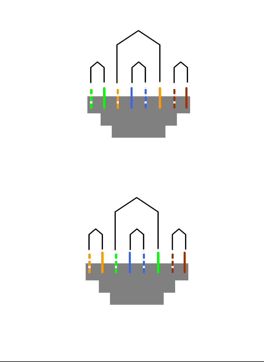
Appendix B: Ethernet Cables and Connectors
APCD-LM048-1.3 41
Straight-through Ethernet cables have T568A wiring at both ends while Cross-over cables
have T568A at one end and T568B at the other end.
Figure 8 T568A Wiring
Figure 9 T568B Wiring
Pair 2
T568A W iring Scheme
Pair 3 Pair 1 Pair 4
T568B W iring Scheme
Pair 3
Pair 2 Pair 1 Pair 4

42 APCD-LM048-1.3
Appendix B: Ethernet Cables and Connectors

:
APCD-LM048-1.3 43
Index
A
Auto CCU Discovery . . . . . . . . . . . . . . . . . . . . . . . . . . . . . . . 4, 11, 12, 16, 23, 36, 37
Automatic Remote Configuration . . . . . . . . . . . . . . . . . . . . . . . . . . . . . . . 3, 4, 36, 38
C
CCU . . . . . . . . . . . . . . . . . . . . . . . . . . . . . . . . . . . . . . . . 19, 23, 24, 25, 33, 34, 36
D
DHCP . . . . . . . . . . . . . . . . . . . . . . . . . . . . . . . . . . . . . . . . . . . 3, 4, 23, 32, 34, 37
E
Ethernet . . . . . . . . . . . . . . . . . . . . . . . . . . . . . . . . . . . . . . . . . . . . . . . . . . . . . . 31
F
FCC. . . . . . . . . . . . . . . . . . . . . . . . . . . . . . . . . . . . . . . . . . . . . . . . . . . xii, xiii, xiv
I
Industry Canada. . . . . . . . . . . . . . . . . . . . . . . . . . . . . . . . . . . . . . . . . . . . . . . . . xii
L
lightning arrestor . . . . . . . . . . . . . . . . . . . . . . . . . . . . . . . . . . xv, 6, 7, 24, 29, 30, 39
local link IP address . . . . . . . . . . . . . . . . . . . . . . . . . . . . . . . . . . . . . . . . . . . . 4, 37
M
MDB1000 . . . . . . . . . . . . . . . . . . . . . . . . . . . . . . . . . . . . . . . . . . . . . . . . . . . . 4, 9
N
NEC . . . . . . . . . . . . . . . . . . . . . . . . . . . . . . . . . . . . . . . . . . . . . . . . . . . . . . . . xvi
P
PoE . . . . . . . . . . . . . . . . . . . . . . . . . . . . . . . . . . . . . . . . . . . . . . . . . . . . . . xv, xvi
polarization . . . . . . . . . . . . . . . . . . . . . . . . . . . . . . . . . . . . . . . . . . . . . . . . . 4, 5, 6
R
RADIUS . . . . . . . . . . . . . . . . . . . . . . . . . . . . . . . . . . . . . . . . . . . . . . . 3, 4, 36, 38
S
security . . . . . . . . . . . . . . . . . . . . . . . . . . . . . . . . . . . . . . . . . . . . . . . . . . . . . . 23
software license agreement . . . . . . . . . . . . . . . . . . . . . . . . . . . . . . . . . . . . . . . . . iii
W
warranty . . . . . . . . . . . . . . . . . . . . . . . . . . . . . . . . . . . . . . . . . . . . . . . . . . . . . . iv